av systems design - bicsi system design.pdfs design d fiber optics ... / 1000 feet in the video...
TRANSCRIPT

AV SystemAV SystemAV SystemAV Systemyyyy
Twisted Pair anTwisted Pair anKarl Rosenberg Karl Rosenberg -- EE
krosenberg@krosenberg@krosenberg@krosenberg@
ms Designms Designms Designms Designgggg
nd Fiber Opticsnd Fiber OpticsppExtronExtron ElectronicsElectronics

ObjecObjec
Video Signal CharacteristicsVideo Signal CharacteristicsggAnalog Video Loss and ComAnalog Video Loss and ComAnalog Video SolutionsAnalog Video SolutionsAnalog Video SolutionsAnalog Video Solutions–– Coaxial Coaxial -- Twisted Pair Twisted Pair -- FiberFiber
T i t d P i i A/VT i t d P i i A/VTwisted Pair in A/VTwisted Pair in A/VFiber in A/VFiber in A/V
ctivesctives
ssmpensationmpensation

TransmissioTransmissio
oaxialoaxialPA 300PA 300PA 300PA 300
Up to 150Up to 150
wisted Pairwisted PairMTP TxMTP Tx
wisted Pairwisted Pair
Up to 1Up to 1
ber Opticber OpticFOXBOX TxFOXBOX Tx
on methodson methods
Up to 600’Up to 600’pp
00’00’
MTP RxMTP Rx
18 miles18 miles
FOXBOX RxFOXBOX Rx
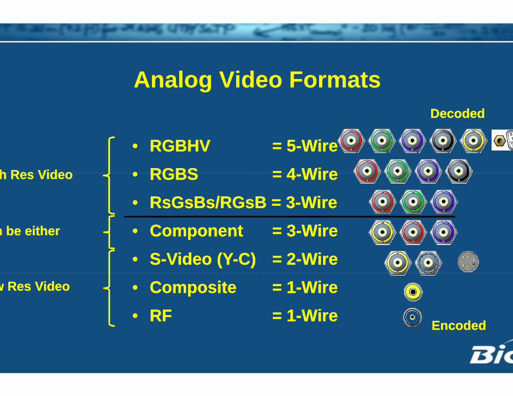
A l VidAnalog Vide
• RGBHV • RGBS• RGBHV • RGBSh Res Videoh Res Video • RGBS • RsGsBs/RGsB• RGBS • RsGsBs/RGsB
h Res Videoh Res Video
• Component • S-Video (Y-C) • Component • S-Video (Y-C)
n be eithern be either
• Composite • RF • Composite • RF
w Res Videow Res Video
F teo FormatsDecodedDecoded
= 5-Wire= 4 Wire= 5-Wire= 4 Wire= 4-Wire
B = 3-Wire= 4-Wire
B = 3-Wire= 3-Wire= 2-Wire= 3-Wire= 2-Wire= 1-Wire = 1-Wire= 1-Wire = 1-Wire EncodedEncodedEncodedEncoded

Analog SigAnalog Sig
Low Resolution VideoLow Resolution VideoLow Resolution VideoLow Resolution VideoLow Resolution VideoLow Resolution Video–– National Television StandardsNational Television Standards
Low Resolution VideoLow Resolution Video–– National Television StandardsNational Television Standards
720720720720
Field A
Field B
gnal Typesgnal Types
s Committee (NTSC)s Committee (NTSC)s Committee (NTSC)s Committee (NTSC)
262.5 Interlaced262.5 Interlaced
262.5 Interlaced262.5 Interlaced

Analog SigAnalog SigHigh Resolution VideoHigh Resolution VideoHigh Resolution VideoHigh Resolution Video–– Advanced Television SystemsAdvanced Television Systems–– Video Electronics Standards AVideo Electronics Standards A–– Advanced Television SystemsAdvanced Television Systems–– Video Electronics Standards AVideo Electronics Standards A A wide variety of market driven rA wide variety of market driven r A wide variety of market driven rA wide variety of market driven r
20p 1080i
oror
Satellite RxSatellite Rxoror
Blu-rayBlu-ray
gnal Typesgnal Types
s Committee (ATSC)s Committee (ATSC)Association (VESA)Association (VESA)s Committee (ATSC)s Committee (ATSC)Association (VESA)Association (VESA)resolutionsresolutionsresolutionsresolutions
1920x1280
x 1200x800
1440x
9001680
x1050

How far can a vHow far can a v
Distance limitations are baseDistance limitations are base–– FrequencyFrequency Pixel durationPixel duration
–– Type of cable being usedType of cable being used ResistanceResistance CapacitanceCapacitance
–– System capabilitiesSystem capabilities Cumulative system bandwidthCumulative system bandwidth What is the contentWhat is the content
ideo signal go?ideo signal go?
ed on:ed on:

Analog Video – DiAnalog Video Di
No defined distance limitatioNo defined distance limitatio–– Not forced to follow good desiNot forced to follow good desi
35’~50’35’~50’ 75’~100’75’~100’ 135’ +135’ +
Passive PlatePassive Plate
35’~50’35’~50’ 75’~100’75’~100’ 135’ +135’ +
Extender DExtender D
istance with Coaxistance with Coax
nngn practicesgn practices
Signal graduaSignal graduaSignal graduaSignal graduaSignal graduaSignal graduadegrades but degrades but visible long invisible long indegraded statdegraded stat
Signal graduaSignal graduadegrades but degrades but visible long invisible long indegraded statdegraded stat

Electrical CharacElectrical Charac
ResistanceResistance–– Opposition to the flow of electOpposition to the flow of elect–– Specification is given in OhmsSpecification is given in Ohmsp gp g–– Appears as lack of brightnessAppears as lack of brightness
CapacitanceCapacitanceCapacitanceCapacitance–– Electrical charge a cable can Electrical charge a cable can
Affects time it takes for cable tAffects time it takes for cable t–– Affects time it takes for cable tAffects time it takes for cable t How fast can the signal turn off How fast can the signal turn off
Appears as loss of image shaAppears as loss of image sha–– Appears as loss of image shaAppears as loss of image sha
cteristics of Cablecteristics of Cable
tronstronss / 1000 feets / 1000 feet in the video image in the video image
holdholdto charge and dischargeto charge and dischargeto charge and dischargeto charge and dischargeand on?and on?rpnessrpnessrpnessrpness

Cable LossCable Loss
Resistance and capacitance Resistance and capacitance pp
12’12’
Quality of cable alsoQuality of cable also impacimpac100’100’
Quality of cable alsoQuality of cable also impacimpac•• Limiting signal lossLimiting signal loss is ALWAis ALWA
•• Better cable less lossBetter cable less lossBetter cable, less lossBetter cable, less loss
s Artifactss Artifacts
work together work together gg
To affectTo affect•• BrightnessBrightnessTo affectTo affect•• BrightnessBrightness
cts the amount of losscts the amount of loss
gg•• ContrastContrast•• SharpnessSharpness
gg•• ContrastContrast•• SharpnessSharpness
cts the amount of losscts the amount of lossAYS better than compensationAYS better than compensation

Video ComVideo Com
Level controlLevel control–– Compensates for long distancCompensates for long distanc resistanceresistance
Peaking controlPeaking control–– Compensates for high frequenCompensates for high frequenCompensates for high frequenCompensates for high frequen Cable capacitanceCable capacitance Multiple system componentsMultiple system componentsp y pp y p
Controls are available on IntControls are available on Intsome Distribution Amplifierssome Distribution Amplifierssome Distribution Amplifierssome Distribution Amplifiers
mpensationmpensation
cesces
ncy lossncy lossncy lossncy lossRGB 203RxiRGB 203Rxi RGB 1RGB 1
erfaces, Line Drivers and erfaces, Line Drivers and

Electrical CharacElectrical Charac
ImpedanceImpedancepp–– Combination of resistance andCombination of resistance and
Video is a 75 Ohm matchedVideo is a 75 Ohm matchedVideo is a 75 Ohm matched Video is a 75 Ohm matched –– Mismatch in impedance canMismatch in impedance can
cause signal reflectionscause signal reflectionscause signal reflectionscause signal reflections
K i i i 75 OhK i i i 75 OhKeys to maintaining 75 OhmKeys to maintaining 75 Ohm–– Good quality cableGood quality cable–– Proper terminationProper termination
cteristics of Cablecteristics of Cable
d reactanced reactanceimpedance systemimpedance systemimpedance systemimpedance system
i di dm impedancem impedance

Signal Loss aSignal Loss a
Loss causes video to displayLoss causes video to displayp yp yLoss affectsLoss affects–– Rise time (increases)Rise time (increases)Rise time (increases)Rise time (increases)–– Amplitude (decreases)Amplitude (decreases)
Loss increases jitterLoss increases jitterLoss increases jitterLoss increases jitter–– If a pixel has no “shelf” then thIf a pixel has no “shelf” then th
l k t i i l hl k t i i l hlocks to a moving signal, henclocks to a moving signal, henc
and the Pixeland the Pixel
y poorlyy poorlyy p yy p y
he displayhe displayhihice shimmerce shimmer

Why Use TwAV Signal Tra
wisted Pair ansmission?

Wh TWhy use TwLong Distance Transmissiong– High resolution analog signals
over twisted pair cable compa
Up to 1500Up to 1500
12001200MTP TxMTP Tx
12001200PA 300PA 300
i t d P i ?wisted Pair?ns can be sent 2 to 3 times fartherared to coaxial cable
0’0’
MTP RxMTP Rx
Up to 600’Up to 600’

Wh TWhy use TwSmaller size cable– Limited conduit space Requires less space
– Environmental impact Historical buildings (run externa May eliminate the need to core o May eliminate the need to core o
0.357 in9.17 mm
0.792 in20.12 mm
0.240 in6.09 mm
0.118 in3 mm
MHR 5 RG6 5 Sk F SM Si lMHR-5 RG6-5 Skew-Free SM Simplex
Coax Coax Twisted Pair
Fiber
i t d P i ?wisted Pair?
lly)or trench flooror trench floor

Wh TWhy use TwImproved noise immunityp y– Audio and Video are run balan
RFI
Twisted Pair
CCoax
i t d P i ?wisted Pair?
nced so noise is cancelled out
EMI

Why use TwWhy use Tw
Use of existing cable infrastrg– Many facilities will have unuse
terminated twisted pair cable pthroughout the building that thIntegrator can use
Twisted pair cable can also bfaster and less expensive to compared to coaxial cable
wisted Pair?wisted Pair?
ructureed pre-pulled
he A/V
be easier, terminate
Extron VGA Cable

TP integratTP integrat
Compensating for long cableCompensating for long cablep g g– Level– Peaking
p g g– Level– Peakingg
Compensating for different pSkew
gCompensating for different p
Skew– Skew– Skew
ion into AVion into AV
e runse runs
pair twists (lengths)pair twists (lengths)

LevLev
Brightness loss due to cable Brightness loss due to cable gg
velvel
resistanceresistance

Level AdjLevel Adj
Restore signal level to 0.7 VogTo visually assess image qu– CrosshatchCrosshatch– Checkerboard – H pattern– Alternating pixel
RGBHVTwisted Pair
justmentjustment
oltality
No CompensationWith Compensation
RT

P kPeakSmearing and sharpness losg p– Low frequencies are comprom– High frequencies are rolled offHigh frequencies are rolled off
Normal H
kikingss due to cable capacitancepmised resulting in “smearing”f resulting in loss of “sharpness”f resulting in loss of sharpness
H Pattern

Multi-Stage PeakMulti-Stage Peak
Recover rise timeTo visually assess image qu– Crosshatch– Checkerboard – H pattern
Alternating pi el– Alternating pixel
RGBHVTwisted Pair
king Adjustmentking Adjustment
ality
No CompensationWith Compensation
RGBHRGBHTwiste

WiWire Determines if the cable has b– According to a standard - T56
MMapbeen terminated correctlyy8A

SkeSke
Relates to twist ratio per pairp pLength of the conductors wil
300’300’
ewew
rl vary between pairs
5 twists5 twists
319’319’319’319’
310’310’
3 twists3 twists
310310
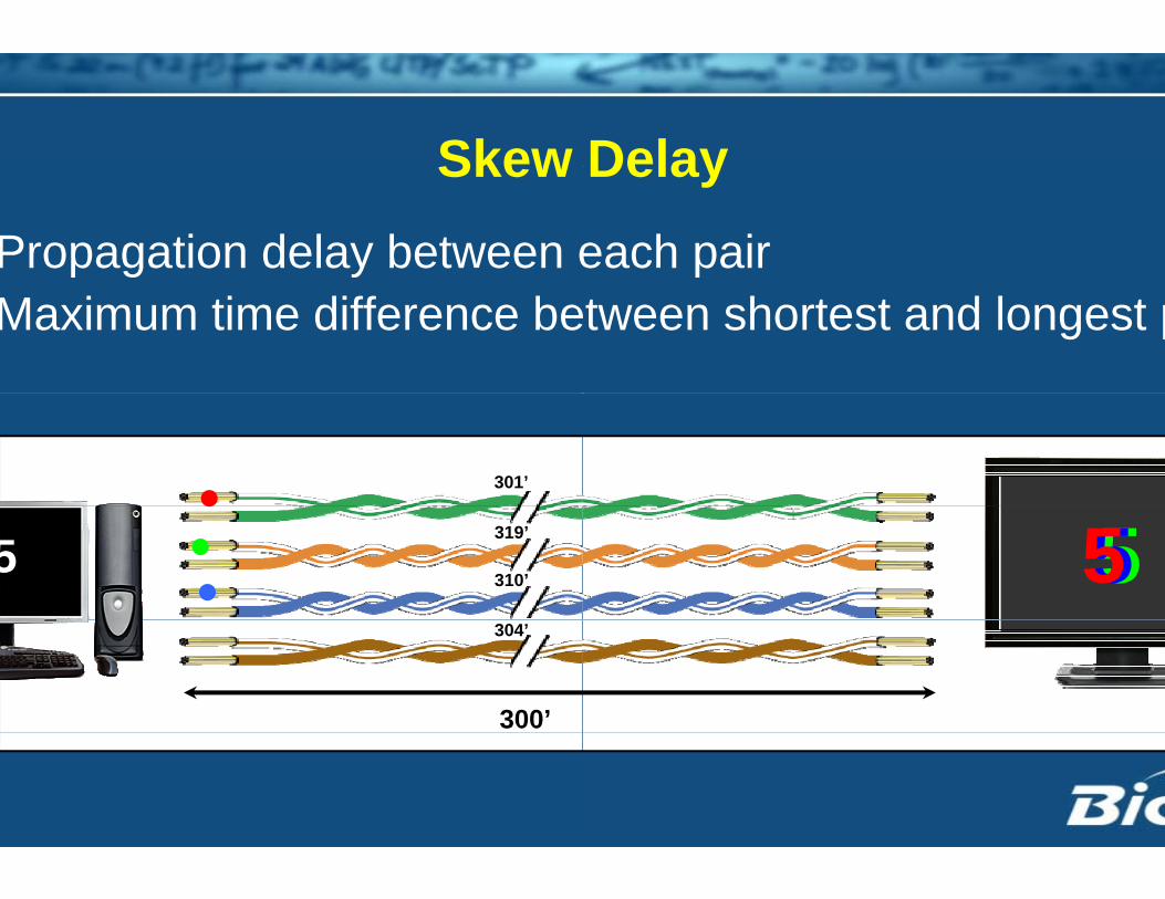
SkewSkew Propagation delay between eMaximum time difference be
301’
319’
310’25
304’
300’
DelayDelay each pair
etween shortest and longest p
555

Pixel BePixel Be
Cable with skew delay of 0.2Cable with skew delay of 0.2y– At 30 meters => delay = 7.5ns
y– At 30 meters => delay = 7.5ns
1024 x 768 @ 60Hz
15 ns
1024 x 768 @ 60Hz
½ pixel sh
Pixel Clock = 65 MHzPixel Clock = 65 MHz
ehaviorehavior
25ns per meter25ns per meterps
ps
1280 x 1024 @ 60Hz
8 ns
1280 x 1024 @ 60Hz
ift 1 pixel shift
Pixel Clock = 135 MHzPixel Clock = 135 MHz
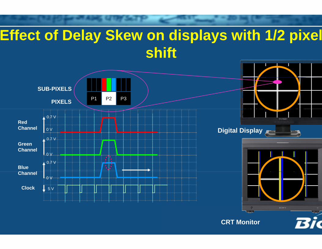
Effect of Delay Skew onsh
P2 P3P1PIXELS
SUB-PIXELS
Red Channel
0.7 V
0 V
0.7 V
Blue Ch l
Green Channel
0.7 V
0.7 V
0 V
Clock
Channel
5 V
0 V
n displays with 1/2 pixelhift
Digital Display
CRT Monitor

ffect of Delay Skew on dffect of Delay Skew on d
P2 P3P1PIXELS
SUB-PIXELS
Red Channel
0.7 V
0 V
0.7 V
Blue Ch l
Green Channel
0.7 V
0.7 V
0 V
Clock
Channel
5 V
0 V
displays with 1 pixel shidisplays with 1 pixel shi
Digital Display
CRT Monitor

Network CoNetwork Co
No match!No match!– Our signals can damage netw Some Twisted Pair products hav
– Our signals can damage netw Some Twisted Pair products havp
voltages Our signals are analog
N t k h d i d i d f
pvoltages Our signals are analog
N t k h d i d i d f Network hardware is designed f Network hardware is designed f
ompatibilityompatibility
work hardwareve large DC
work hardwareve large DC g
f di it l i l
g
f di it l i lfor digital signalsfor digital signals

Mixing and Matching TMixing and Matching TAll manufacturers follow theiCurrently no A/V standard inTransmissionTransmission
ed
Twisted Pair productsTwisted Pair productsr own product design procesp g p
n Twisted Pair signal

Fib O tiFiber OpticTransmTransm
AV Si lc AV Signal missionmission

Why uWhy uImmune to electrical interf
I t EMI RFI li ht– Immune to EMI, RFI or light– No common group required
Coax Receiver
Fiber Receiver
Power Line
Coax
Fib
Receiver
Fiber Receiver
se fiber?se fiber?ferencet i t iktning strikes
d – No ground loops
Bit errors
Bit errors

Why uWhy uSmaller than copper cables– Less weight and Cheaper to t– Higher density
216-fiber optical ribbon cable has samecables
se fiber?se fiber?
transport
e effective cross-sectional area as two (2) CAT 6

Why uWhy uLower Energy Consumption– Green” building initiatives Approximately 20% of the ener
based systembased system Fewer/smaller cables equal bet
se fiber?se fiber?n
rgy required for a comparable copper
tter airflow in racks

B fit f FibBenefits of FibeSecure transmissionResistant to ground loopsLow AttenuationLow AttenuationEMI/RFI ImmunityLightweight
i AV tr in AV systems

T i iTransmissiTransmitters convert electricReceivers convert light to eleTwo Types of Light sourcesTwo Types of Light sources– LED - Light Emitting Diode Multimode fiber cable Multimode fiber cable
– LASER - Light Amplification by St Singlemode and Multimode fibe Singlemode and Multimode fibe Extron uses lasers in all product
i M th dion Methodcal to light energyg gyectrical energy
timulated Emission of Radiationr cabler cablets

Fib OSinglemode - long distanceSinglemode - long distance
Fiber Op
• Core size 8 to 9 micrometers and• Only allows one mode/path of lig• Low losses typically 0.2 to 0.4 d
• Core size 8 to 9 micrometers and• Only allows one mode/path of lig• Low losses typically 0.2 to 0.4 dLow losses typically 0.2 to 0.4 dLow losses typically 0.2 to 0.4 d
M lti d h t di tM lti d h t di tMultimode - short distance• Core size typically 50 or 62.5 mic• Allows more than one mode/path
Multimode - short distance• Core size typically 50 or 62.5 mic• Allows more than one mode/pathAllows more than one mode/path• Typical loss 1 to 6 dB/Km
Allows more than one mode/path• Typical loss 1 to 6 dB/Km
ti C blesestic Cable
d transmits at 1310, 1550 nmghtB/Km
d transmits at 1310, 1550 nmghtB/Km Singlemode fiberSinglemode fiberB/KmB/Km Singlemode fiberSinglemode fiber
escrometers and transmits 850, 1300 nh of light
escrometers and transmits 850, 1300 nh of lighth of lighth of light
Multimode fiberMultimode fiber

Fib AttFiber AttAttentuation is the loss of lig– Extrinsic Splices
C Connectors End finishes CouplersCouplers Macrobends Microbends
– Intrinsic Absorption
S tt i Scattering
tienuationht or signal power
MacrobendMacrobend

PLLClock
8 Bit - RedAD
Multiplexer8 Bit - GreenAD
8 Bit - BlueAD
AAD
2 x18 Bit Audio
LevelTranslator Serial RS-232
T ittTransmitter
OpticalConverter

eceiver
OpticalConverter
DM
SSClock
PLL
R8 Bit - Red DA
G8 Bit - Green DA
De-Multiplexer
B8 Bit - Blue DA
DAu
DA
2 x18 Bit Audio

LossLoss
OpticalOpticalOptical budget
7 dB
Optical budget
7 dB
Optical budgOptical budgFiberM iMatrix
Switch
Optical budget Optical budget Optical Optical p
budget13 dB
pbudget
13 dB
BudgetBudget
OpticalOpticalOptical budget
7 dB
Optical budget
7 dB
get 7 dB MMget 7 dB MMr x
her
13 dB SM13 dB SMOptical Optical p
budget13 dB
pbudget
13 dB

ses of Fiber opticsses of Fiber opticsFiber based systems are employed in commercialemployed in commercial, residential, medical, military/defense, education,y , ,very large scale facilities.
, and ,