asco 7000 series power transfer switches · asco withstand and closing ratings for all 7000 series...
TRANSCRIPT

ASCO 7000 SERIESPower Transfer Switches
ascopower.com

Protecting:
• Healthcare Facilities• Enterprise / Colocation / Cloud Data Centers• Commercial Buildings / Industrial Buildings• Telecom Mobile / Central Switching Centers• Process Manufacturing• Distributed Energy Resources (Microgrid) / Load Management• Water Treatment Facilities
ASCO 7000 Series POWER TRANSFER SWITCHES

As society becomes increasingly dependent on the quality and reliability of electrical power, interruption or complete loss of power can result in serious hardships, significant financial losses, or dangers to life and safety.
ASCO Power Technologies (ASCO) provides industry-leading products and solutions for reliably transferring critical loads to emergency power sources. Using ASCO products can mean the difference between a minor inconvenience and a major catastrophe. You’ll find ASCO Power Transfer Switches wherever there is a critical load to protect.
ASCO offers a variety of product solutions to meet virtually every requirement, including distributed generation applications. That’s why the 7000 series is available in open, delayed, closed and soft load transition configurations. Additionally, switched or overlapping neutral options provide for more accurate operation of ground fault protection systems and reduction of voltage transients from unbalanced load switching.
• Conventional two-position transfer configuration, plus closed and delayed transition modes of operation. All configurations available with either automatic or non-automatic control.
• Listed to UL 1008 Transfer Switch Equipment for Automatic Transfer Switches and Certified to CSA 22.2, No. 178.• Qualified and certified to IEC 60947-6-1, CE marked (optional). (Limited to certain accessories.)• Rated up to 600 VAC, 30 through 4000 amps.• 3 to 18-Cycle Withstand and Closing Rating (WCR) Standard, 30-Cycle WCR Optional.• Reliable and field-proven solenoid operating mechanism.• High WCRs including short-time withstand current rating for optimum flexibility in circuit breaker coordination (600-4000
amps).• Solid, switched, or overlapping neutral conductor options.• Front replaceable main and arcing contacts (800-4000 amps).• Programmable microprocessor controller with keypad and LCD display.• Centrally located terminal block for customer control connections (260-4000 amps).• 16mm, industrial grade control switches and indicating lights.• Switch position and source acceptability LED indicators.• Standard ground conductor connections.• Four auxiliary contacts, two contacts closed when switch is in normal position and two contacts closed when switch
is in emergency position.• Local/remote communications capability for interfacing with ASCO POWERQUEST® communication products.• Protected by a comprehensive 2, 5, or 10 year warranty.
7000 Series
7000 SERIES POWER TRANSFER SWITCHES PRODUCT FEATURES
ASCO Power Transfer Switches are the standard of the industry. High speed transfer of loads between alternate sources of power, regardless of ampacity, is achieved using a reliable, field-proven solenoid operating mechanism. When combined with a programmable microprocessor controller with keypad and LCD display, they offer the most advanced method of transferring all types of loads, such as motors, electronic drives, UPS’s and microprocessor-based systems. 7000 series Power Transfer Switches are available open or enclosed, in ampacities ranging from 30 through 4000 amps with the largest selection of optional accessories offered anywhere. All switching configurations are available with an integrally mounted bypass-isolation switch. Configurations are also available for service entrance applications.
Fig. 1: Three Pole 7000 SerieS Automatic Transfer Switch rated 1600 amps
(shown with optional front connected terminals and Power Meter).
3

The Recognized Leader in Power Transfer Switch Technology Offers the Most Advanced Transfer Switches in the World.
ASCO 7000 SERIES POWER SWITCHING SOLUTIONS
Automatic & Non-Automatic Transfer Switching
ASCO Transfer Switches are available in both automatic & non-automatic initiation types. Both types are electrically operated. For automatic transfer switches, the controller initiates transfer. For non-automatic transfer switches, the user initiates switching transfer between power sources using switches mounted locally or at remote locations. Non-automatic switches have the following features:
• Sizes from 30 through 4000 amps.
• Microprocessor-based controller provides for addition of optional accessories.
• Controller prevents inadvertent operation under low voltage conditions.
• Low control circuit operating currents allow for long distances between remotely mounted manual control switches and the transfer switch.
• Source acceptability lights inform operator when sources are available to accept load.
• Standard inphase monitor can be activated for transferring motor loads.
Fig. 2: Four Pole, Non-Automatic, Electrically-Operated 400 Amp Switch in a Type 1 Enclosure.
4

ASCO 7000 SERIES POWER SWITCHING SOLUTIONS
Open Transition Transfer Switching
ASCO Transfer Switches are available in a standard, 2-position, open transition configuration to reliably transfer loads between power sources. Loads transfer to the alternate source in less than 100ms. In phase transfer can be activated for transferring motor loads. Open transition switches are suitable for a wide range of applications.
• Available from 30 to 4000 amps.
• Utilizes reliable, field-proven, single solenoid operating mechanisms.
• Single operator design prevents direct connection of both sources.
Delayed Transition Transfer Switching
ASCO Delayed Transition Transfer Switches are designed to provide transfer of loads between power sources with a timed load disconnect position for an adjustable period of time. Applications include older style variable frequency drives, rectifier banks, and load management applications.
• 150 through 4000 amps.
• Utilizes reliable, field-proven solenoid operating mechanisms.
• Mechanical interlocks to prevent direct connection of both sources.
• Indicator light (16mm, industrial grade type LED) for load disconnect position.
• Adjustable time delay for load disconnect position.
Closed Transition Transfer Switching
ASCO Automatic Closed Transition Transfer Switches feature main contacts that overlap, permitting the transfer of electrical loads without power interruption. The switch transfers in a make-before-break mode if both sources are within acceptable parameters. Control logic continuously monitors source conditions and automatically determines whether the load transfer should be open (conventional non-overlap mode) or closed transition.
• Available 150 through 4000 amps.
• Utilizes reliable, field proven solenoid operating mechanism.
• Closed Transition Transfer is achieved passively within 5 electrical degrees, without control of engine generator set.
• Additional control wiring not required.
• Overlap time is less than 100 milliseconds (consult your local utility on protective relay requirements).
• Failure to synchronize and extended parallel time indication.
Fig. 3: Four pole, Delayed Transition 2000 Amp Transfer Switch.
Fig. 4: Four Pole, Closed Transition, 1000 Amp Transfer Switch in a Type 1 enclosure.
5
WITHSTANDING AND CLOSING ON SHORT CIRCUIT FAULT CURRENTS
Withstanding and closing on short circuit currents require transfer switches that can handle extremely high electromagnetic forces and thermal stresses. Circuit breakers and fuses are designed to open on short circuit currents. However, while transfer switches must withstand a short circuit current until the over-current device clears the fault.
The withstand and closing rating (WCR) indicates the highest level of current a transfer switch can close on and carry for a specific amount of time. For system coordination purposes, the time must be sufficient for the upstream over-current protective device to clear the fault. The WCR must equal or exceed the available fault current and system voltage at the power source terminals of the switch.
The purpose of a power transfer switch is to maintain power to the load, whereas an overcurrent device is designed to open under a fault condition to protect the circuit conductors and equipment. ASCO power transfer switches use a unique solenoid operator design to force and lock the main contacts closed on a high current fault, rather than allowing them to open like a circuit breaker.
Main contact material composition, contact geometry, arcing contact design, and other features all affect the ability of the power transfer switch to withstand and close-on high fault currents. ASCO employs a variety of computer modeling programs to determine the optimal combination of all these elements to create a superior transfer switch design. ASCO power transfer switches are available with a full range of WCRs to accommodate a variety of over-current devices with fault-clearing times from 0.004 to 0.5 seconds (1/4 to 30 cycles). In fact, ASCO transfer switches provide the industry’s most comprehensive solution for all short circuit requirements. Our 7000 SERIES WCR table addresses all time-based, specific break-er, current-limiting fuse, and short-time ratings necessary for accommodating selective coordination requirements.
In order to meet NEC selective coordination requirements, short-time settings are specified on circuit breakers following a coor-dination study. A circuit breaker’s short-time settings require transfer switches to withstand and close-on short circuit currents for time durations of 0.1 seconds (6 cycles for a 60Hz system) or longer. The 4th Edition of UL1008 added this optional “Short-Time Rating” for transfer switches in 2002. Underwriters Laboratories does not require a specific time or specific number of cycles to qualify for this rating, but the transfer switch WCRs must coordinate with the short-time settings on the breakers.
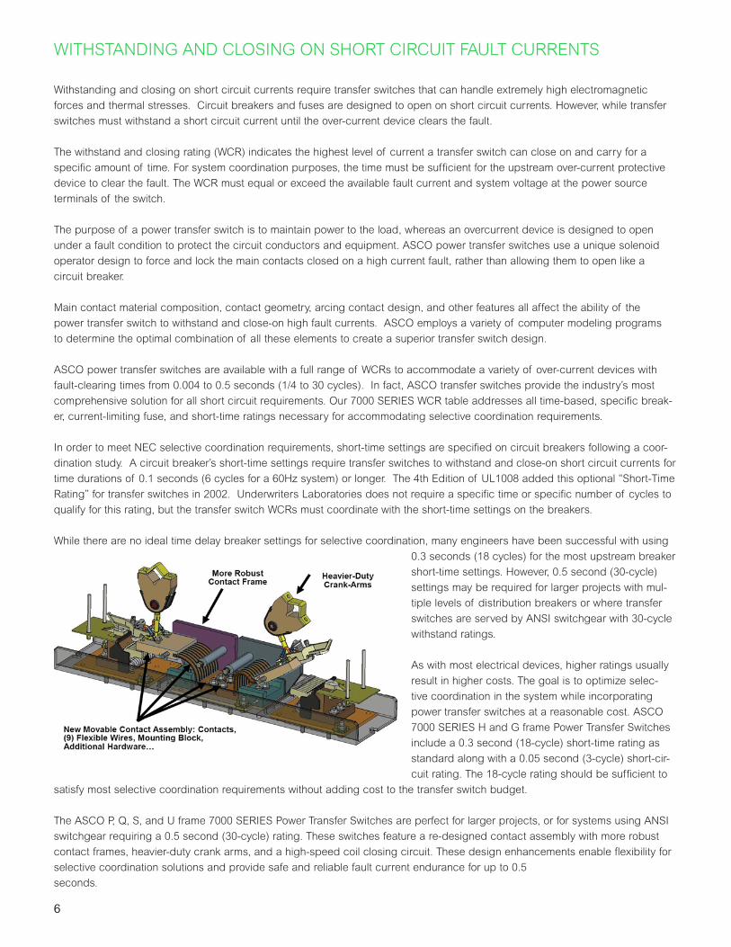
While there are no ideal time delay breaker settings for selective coordination, many engineers have been successful with using 0.3 seconds (18 cycles) for the most upstream breaker short-time settings. However, 0.5 second (30-cycle) settings may be required for larger projects with mul-tiple levels of distribution breakers or where transfer switches are served by ANSI switchgear with 30-cycle withstand ratings.
As with most electrical devices, higher ratings usually result in higher costs. The goal is to optimize selec-tive coordination in the system while incorporating power transfer switches at a reasonable cost. ASCO 7000 SERIES H and G frame Power Transfer Switches include a 0.3 second (18-cycle) short-time rating as standard along with a 0.05 second (3-cycle) short-cir-cuit rating. The 18-cycle rating should be sufficient to
satisfy most selective coordination requirements without adding cost to the transfer switch budget.
The ASCO P, Q, S, and U frame 7000 SERIES Power Transfer Switches are perfect for larger projects, or for systems using ANSI switchgear requiring a 0.5 second (30-cycle) rating. These switches feature a re-designed contact assembly with more robust contact frames, heavier-duty crank arms, and a high-speed coil closing circuit. These design enhancements enable flexibility for selective coordination solutions and provide safe and reliable fault current endurance for up to 0.5 seconds.
6

ASCO Withstand and Closing Ratings for all 7000 SERIES Products1,2
(RMS Symmetrical Amps)
The chart below indicates Withstand and Closing Ratings for all 7000 series Power Transfer Switches, including 0.5 second (30-cycle) designs.
Notes:1. All WCR values indicated are tested in accordance with the requirements of UL 1008, 7th Edition. See ASCO Pub. 1128 for more WCR information.2. Application requirements may permit higher WCR for certain switch sizes.3. Short Time ratings are provided for applications involving circuit breakers that utilize trip delay settings for system selective coordination.4. Max fuse rating is 1200A on front connected H frame switches.5. Switches utilizing overlapping neutral (code "C") have 35kA, 0.050 Sec time based rating at 480V Max.6. Rating shown is for Bypass switches only, Transfer Switch rating is 100kA.7. Contact ASCO for Service Entrance Switch ratings.8. Short Time Rating applies to 600A Bypass switch only, the 600A Transfer Switch does not have a Short Time Rating.
480V Max.
600V Max.
Max Size, A Class 240V
Max.480V Max.
600V Max.
Time (sec)
240V Max.
480V Max.
600V Max. .13 .2 .3 .5 .1 .13 .3 .5
100kA - 300 J200kA 35kA 200 J35kA 35kA 200 RK135kA 35kA 200 RK1200kA 35kA 200 J35kA 35kA 200 RK1200kA 35kA 200 J
D 200 - 200kA - 200 J 200kA 85kA 14kA 0.025 10kA 10kA 10kAD 230 - 100kA - 300 J 200kA 85kA 14kA 0.025 10kA 10kA -E 260, 400 - 200kA - 600 J 65kA 42kA 35kA 0.05 35kA 35kA 22kA
600 J800 L600 J800 L
200kA 200kA 800 L200kA 200kA 600 J
H8 600 600 200kA 200kA 1600 L 65kA 65kA 65kA 0.05 50kA 50kA 50kA - -P8 600 600 200kA 200kA 1600 L 65kA 65kA 65kA 0.05 50kA 50kA 50kA 30kA -P8 800 800 - 1200 200kA 200kA 1600 L 65kA 65kA 65kA 0.05 50kA 50kA 50kA 30kA -H 800 - 1200 800 - 1200 200kA 200kA 16004 L 65kA 65kA 65kA 0.05 50kA 50kA 50kA - -Q8 600-1600 600-1600 200kA 200kA 2000 L 65kA 65kA 65kA 0.05 65kA 65kA 65kAS8 800 - 1200 800 - 1200 200kA 200kA 2500 L 100kA 100kA 65kA 0.05 100kA 100kA 65kAG8 1000 - 1200 1000 - 1200 200kA 200kA 2000 L 85kA 85kA 85kA 0.05 85kA 85kA 85kAG 200kA 200kA 2500 L 85kA 85kA 85kA 0.05 85kA 85kA 85kA 36kAG8 1600 - 2000 1600 - 2000 200kA 200kA 3000 L 125kA6 125kA6 100kA 0.05 100kA 100kA 100kA 36kA -S8 1600 - 2000 1600 - 2000 200kA 200kA 2500 L 100kA 100kA 85kA 0.05 100kA 100kA 85kA 65kA 65kAG 2600 - 3000 2600 - 3000 200kA 200kA 4000 L 100kA 100kA 100kA 0.05 100kA 100kA 100kA 36kA -G8 3200 - 200kA - 4000 L 100kA 100kA - 0.05 100kA 100kA -G 4000 4000 200kA 200kA 5000 L 100kA 100kA 100kA 0.05 100kA 100kA 100kA 85KAU8 2600 - 4000 2600 - 4000 200kA 200kA 5000 L 125kA 125kA 125kA 0.05 125kA 125kA 125kA
Notes: 1) All WCR values indicated are tested in accordance with the requirements of UL 1008, 7th Edition. See ASCO Pub. 1128 for more WCR information2) Application requirements may permit higher WCR for certain switch sizes.3) Short Time ratings are provided for applications involving circuit breakers that utilize trip delay settings for system selective coordination4) Max fuse rating is 1200A on front connected H frame switches5) Switches utilizing overlapping neutral (code "C") have 35kA, 0.050 Sec time based rating at 480V Max6) Rating shown is for Bypass switches only, Transfer Switch rating is 100kA7) See ASCO for Service Entrance Switch ratings8) These frames are only available on the 7000 Series product9) Short Time Rating applies to 600A Bypass switch only, the 600A Transfer Switch does not have a Short Time Rating
J 150, 200, 260 150, 200, 230, 260 200kA 200kA 200kA 200kA 42kA 0.05
1600 - 2000 (Front Connected TS Only)
J 600 600
0.05 65kA 42kA5 35kA200kA 200kA 65kA
65kA 50kA 42kA 0.05 65kA 42kA5 35kA
J 400 400
-
50kA 42kA
10kA 10kA - -
-10kA
-
7.5kA9
7.5kA -
-
65kA 42kA5 35kA 7.5kA - -
D 30 - 22kA 22kA 10kA 0.025 10kA
85kA 25kA 10kA
300, 4000 & 7000 Series 4000 & 7000 Series
6-Aug-18
(RMS Symmetrical Amps)
Short Time Ratings3 (sec)
Transfer Switches Bypass Switches
480V Max. 600V Max.Frame
Switch Rating (Amps) Current Limiting Fuses Specific Breaker
7000 Series
D 70, 100 10kA
D 150 - 150kA 85kA
- 150kA
ASCO UL1008 Withstand and Closing Ratings 1,2,7
42kA 42kA
36kA 36kA36kA 36kA
- -- -
25kA 10kA 10kA 10kA
65kA
Time Based
0.025
0.025 -
- -
-
-
42kA 42kA-
100kA 100kA
36kA 36kA
36kA 36kA
-
85kA
65kA-
65kA-
85kA
-
50kA 50kA
65kA
42kA
480V Max.
600V Max.
Max Size, A Class 240V
Max.480V Max.
600V Max.
Time (sec)
240V Max.
480V Max.
600V Max. .13 .2 .3 .5 .1 .13 .3 .5
100kA - 300 J200kA 35kA 200 J35kA 35kA 200 RK135kA 35kA 200 RK1200kA 35kA 200 J35kA 35kA 200 RK1200kA 35kA 200 J
D 200 - 200kA - 200 J 200kA 85kA 14kA 0.025 10kA 10kA 10kAD 230 - 100kA - 300 J 200kA 85kA 14kA 0.025 10kA 10kA -E 260, 400 - 200kA - 600 J 65kA 42kA 35kA 0.05 35kA 35kA 22kA
600 J800 L600 J800 L
200kA 200kA 800 L200kA 200kA 600 J
H8 600 600 200kA 200kA 1600 L 65kA 65kA 65kA 0.05 50kA 50kA 50kA - -P8 600 600 200kA 200kA 1600 L 65kA 65kA 65kA 0.05 50kA 50kA 50kA 30kA -P8 800 800 - 1200 200kA 200kA 1600 L 65kA 65kA 65kA 0.05 50kA 50kA 50kA 30kA -H 800 - 1200 800 - 1200 200kA 200kA 16004 L 65kA 65kA 65kA 0.05 50kA 50kA 50kA - -Q8 600-1600 600-1600 200kA 200kA 2000 L 65kA 65kA 65kA 0.05 65kA 65kA 65kAS8 800 - 1200 800 - 1200 200kA 200kA 2500 L 100kA 100kA 65kA 0.05 100kA 100kA 65kAG8 1000 - 1200 1000 - 1200 200kA 200kA 2000 L 85kA 85kA 85kA 0.05 85kA 85kA 85kAG 200kA 200kA 2500 L 85kA 85kA 85kA 0.05 85kA 85kA 85kA 36kAG8 1600 - 2000 1600 - 2000 200kA 200kA 3000 L 125kA6 125kA6 100kA 0.05 100kA 100kA 100kA 36kA -S8 1600 - 2000 1600 - 2000 200kA 200kA 2500 L 100kA 100kA 85kA 0.05 100kA 100kA 85kA 65kA 65kAG 2600 - 3000 2600 - 3000 200kA 200kA 4000 L 100kA 100kA 100kA 0.05 100kA 100kA 100kA 36kA -G8 3200 - 200kA - 4000 L 100kA 100kA - 0.05 100kA 100kA -G 4000 4000 200kA 200kA 5000 L 100kA 100kA 100kA 0.05 100kA 100kA 100kA 85KAU8 2600 - 4000 2600 - 4000 200kA 200kA 5000 L 125kA 125kA 125kA 0.05 125kA 125kA 125kA
Notes: 1) All WCR values indicated are tested in accordance with the requirements of UL 1008, 7th Edition. See ASCO Pub. 1128 for more WCR information2) Application requirements may permit higher WCR for certain switch sizes.3) Short Time ratings are provided for applications involving circuit breakers that utilize trip delay settings for system selective coordination4) Max fuse rating is 1200A on front connected H frame switches5) Switches utilizing overlapping neutral (code "C") have 35kA, 0.050 Sec time based rating at 480V Max6) Rating shown is for Bypass switches only, Transfer Switch rating is 100kA7) See ASCO for Service Entrance Switch ratings8) These frames are only available on the 7000 Series product9) Short Time Rating applies to 600A Bypass switch only, the 600A Transfer Switch does not have a Short Time Rating
J 150, 200, 260 150, 200, 230, 260 200kA 200kA 200kA 200kA 42kA 0.05
1600 - 2000 (Front Connected TS Only)
J 600 600
0.05 65kA 42kA5 35kA200kA 200kA 65kA
65kA 50kA 42kA 0.05 65kA 42kA5 35kA
J 400 400
-
50kA 42kA
10kA 10kA - -
-10kA
-
7.5kA9
7.5kA -
-
65kA 42kA5 35kA 7.5kA - -
D 30 - 22kA 22kA 10kA 0.025 10kA
85kA 25kA 10kA
300, 4000 & 7000 Series 4000 & 7000 Series
6-Aug-18
(RMS Symmetrical Amps)
Short Time Ratings3 (sec)
Transfer Switches Bypass Switches
480V Max. 600V Max.Frame
Switch Rating (Amps) Current Limiting Fuses Specific Breaker
7000 Series
D 70, 100 10kA
D 150 - 150kA 85kA
- 150kA
ASCO UL1008 Withstand and Closing Ratings 1,2,7
42kA 42kA
36kA 36kA36kA 36kA
- -- -
25kA 10kA 10kA 10kA
65kA
Time Based
0.025
0.025 -
- -
-
-
42kA 42kA-
100kA 100kA
36kA 36kA
36kA 36kA
-
85kA
65kA-
65kA-
85kA
-
50kA 50kA
65kA
42kA
7

ASCO 7000 SERIES BYPASS ISOLATION SWITCHES
Automatic Transfer Bypass-Isolation Switches
Transfer Switch Drawout Features (150-4000 Amps)
ASCO Automatic Transfer & Bypass-Isolation Switches are available in open transition, closed transition, and delayed transition designs. The bypass and isolation features allow the primary automatic transfer switch to be inspected, tested, and maintained without interrupting power to the load. They also provide redundant power transfer if the ATS is disabled or removed from service.
• Available 150 to 4000 amps.
• Allows bypass-isolation without load interruption.
• Bypass switch and transfer switch have identical electrical ratings.
• Heavy-duty mechanical interlocks prevent unintended operation.
• Bypass contacts carry current only during bypass mode.
• Drawout design allows for easy transfer switch maintenance.
• Bypass and isolation handles are permanently mounted. The bypass switch has dead front quick-make, quick-break operation for transferring loads between live sources.
• Bypass switch is fully rated for use as a manual 3-position transfer switch.
• Bypass and isolation functions are simple, requiring a total of two operating handles.
• No toggle switches, push buttons, selector switches, or levers are required for bypass-isolation operation.
• Mechanical indicators show bypass and transfer switch positions.
• 800 - 1200 amp models available in shallow depth, front connected or rear connected designs.
Fig. 5: J-Frame 150-600 amps
Fig. 6: H-Frame 600-1200 amps
Fig. 7: G-Frame 1000-3000 amps
Fig. 8: G-Frame 4000 amps
• Automatic secondary disconnects remove all control power as switch is withdrawn.
• Drawout carriage provides for easy transfer switch mechanism maintenance and/or removal via commercially available breaker hoists.
• Optional transfer switch lifting yoke kit available
• Optional automatic shutters that close when the transfer switch is withdrawn to provide bus isolation. Specify accessory 82C (1600-3000 Amp only).
AutomaticSecondary
Disconnects
Automatic Shutters
(optional on1600-3000amps)
Self Aligning
Jaws
Fig. 9: Bypass-Isolation Transfer Switch Secondary Disconnects and
Optional Automatic Shutters.
Fig. 10: Bypass-Isolation Transfer Switch Self-Aligning Power Jaws.
8

ASCO 7000 SERIES BYPASS ISOLATION SWITCHES
Bypass and Isolation Handles - Simple as 1, 2, 3
1 Bypass to Normal
N
E
L
Push in bypass handle and turn it counter clockwise
Bypass handle
Isolation handle
Bypass Switch
Automatic Transfer Switch
2 Test Position
N
E
L
Turn isolation handle counter clockwise until window shows “Test”
Isolation handle
Bypass Switch
Automatic Transfer Switch
3 Isolation Position
N
E
L
Turn isolation handle counter clockwise until window shows “isolate”
Isolation handle
Bypass Switch
Automatic Transfer Switch
Isolation handle
Mechanical isolation handle position window (connected/test/isolate)
Bypass switch
position
Transfer switch
position
Source availability
Isolation handleposition
Padlocking provisions
Mechanical bypass switch position flags
9

ASCO 7000 SERIES SERVICE ENTRANCE POWER TRANSFER SWITCHESThe ASCO Service Entrance Power Transfer Switch combines automatic power switching with a disconnect and overcurrent protective device on the utility source. The power transfer switch meets all National Electric Code requirements for installation at a facility’s main utility service entrance. Service entrance rated transfer switches generally are installed at facilities that have a single utility feed and a single emergency power source. A circuit breaker serves as the utility disconnect and links are provided to disconnect both neutral and ground connections. This product is available up to 600V and 4000 amps in Standard, Delayed, Closed Transition, Soft Load, and Bypass Isolation Configurations.
Standard Features
• Available from 70 to 4000 amps
• 70 - 400 amp listed to UL 1008
• 600 - 4000 amp listed to UL 891• The ASCO 7000 series Power Transfer Switch mechanism
is UL 1008 Listed • Standard UL Type 1 Enclosure• Disconnect and overcurrent protective device on the
utility source. 70 to 2000 amp models use molded case circuit breakers; 2500 to 4000 amp models use insulated case circuit breakers.
• Disconnect link on Neutral• Disconnect link on Ground• Ground and Neutral Bus, all silver-plated copper• Solderless screw-type terminals for External Power
Connections• Meets all NEC requirements for use as service entrance• Internet-enabled monitoring and control• Service Entrance Continuous Breaker Ratings: 80% for
standard transfer switches below 2500 amps and Bypass Isolation Switches below 1000 amps, otherwise 100%
Fig. 13: Ground and neutral
disconnect links
Utility
Circuitbreaker
ATSSwitchedNeutral
Ground Fault Current
Transformer*
Emergency
Load
NeutralDisconnect Link
GroundDisconnect Link
N
N
Ø
Ø
GFCT - Ground Fault Current Transformer
ATS - Automatic transfer Switch
One line diagram of a typical service entrance-rated transfer switch available in Solid, Switched or Overlapping Neutral*Ground fault trip protection provided on models of 1000 amps and above
Additional Options
• Enclosures - Secure Door Over Door/Panel- UL Type 3R w/strip heater & thermostat- UL Type 4 or 4X- UL Type 12
• Connections - Crimp lugs - Bus Riser on Normal, Emergency or Load
• Protective Relays/Metering- Accessory 135L (see page 22)
• Surge Suppression- Accessory 73, Surge protector (see page 19)
• Additional Breaker(s)- Circuit Breaker on Emergency- Load Distribution Panel
• Optional High AIC Ratings on Breakers• Technology Packages including
- 7-inch Color Touch Display including 5210 Meter (Acc. 150AT/150BT)- 7-inch Color Touch Display Interface including 5410 Power Quality Meter (Acc. 150AT1/150BT1)- Base Package including 5210 Power Meter (Acc. 150A/150B)
• ATS Remote Annunciators (see page 23)- 1-ATS 7-inch Color Touch Annunciator (5370)- 8-ATS / 1-ATS LED Annunciator (5350/5310)
• Remote Power Monitoring (see pages 25-27)- 8-Device Annunciator, (5705)- Critical Power Management System (5710/5750/5790)
Note: All Tech Packs include Meter, Acc. 72EE2 Ethernet Module and Acc.1PS1 power ride-through. 150A* (ATS) and 150B* (Bypass ATS).
Consult ASCO for additional features
10

ASCO 7000 SERIES GROUP 5 CONTROLLER
The 7000 SERIES Controller (Group 5) is used with all sizes of Power Transfer Switches from 30 through 4000 amps. It is the most reliable and field-proven transfer switch controller in the industry and includes, as standard, all of the voltage, frequency, control, timing and diagnostic functions required for most emergency and standby power applications. It can be equipped with a color Touch Display Interface that provides information to better manage your transfer and bypass switch. (See page 16 for additional information)
Because severe voltage transients are frequently encountered in industrial distribution systems, the controller's logic board is separated and isolated from its power board. This improves electrical noise immunity performance and helps assure compliance with the rigorous transient suppression standards shown in the table below.
7000 SERIES Group 5 Controller
Emission Standard - Group 1, Class A EN 55011:1991
Generic Immunity Standard, from which: EN 50082-2:1995
Electrostatic Discharge (ESD) Immunity EN 61000-4-2:1995
Radiated Electromagnetic Field Immunity ENV 50140:1993
Electrical Fast Transient (EFT) Immunity EN 61000-4-4:1995
Surge Transient Immunity EN 61000-4-5:1995
Conducted Radio-Frequency Field Immunity EN 61000-4-6:1996
Voltage Dips, Interruptions and Variations Immunity EN 61000-4-11:1994
Group 5 Controller Standard Display
Enter/Save SettingsEsc
Increase Value
Decrease Value
Menu Scroll
Menu Scroll
Normal OK
Load on Normal
Advanced Touch Display Interface (TDI)Accessory 150 Tech. Package (see page 16)
11

ASCO 7000 SERIES GROUP 5 CONTROLLER
Control Features
• Touch pad programming of features and settings without the need for meters or variable power supplies.
• Sixteen (16) selectable operating voltages available in a single Controller.
• On-board diagnostics provide control panel and ATS status information for analyzing system performance.
• Displays and counts down active timing functions.
• Selectable multi-language display (English, German, Portuguese, Spanish, or French. For other languages, contact ASCO).
• Password protection to prevent unauthorized tampering of settings.
• Optional Color Touch Display Interface simplifies control management and expands event log to 1,000 events. Specify Accessory 150AT (ATS) or 150BT (Bypass).
• Remote monitoring and control with ASCO POWERQUEST® communication products. Specify Accessory 72EE2.
• Load shed option for bus optimization applications. Specify optional accessory 30B.
• Historical event log.• Statistical ATS systems monitoring information.
Voltage and Frequency Sensing
• 3-Phase under-voltage and over-voltage settings on normal and emergency sources.
• Under-frequency and over-frequency settings on normal and emergency.
• True RMS Voltage Sensing with +/- 1% accuracy; Frequency Sensing Accuracy is +/- 0.2%.
• Selectable settings: single or 3-phase voltage sensing on normal and emergency; 50 or 60Hz.
• Phase sequence sensing for phase-sensitive loads.• Voltage unbalance detection between phases.
Status and Control Functions
• Output contact (N/O or N/C) for engine-start signals.• Selection between “commit/no-commit” on transfer to emergency
after engine start and normal restores before transfer.• Advanced inphase algorithm that automatically measures the
frequency difference between the two sources and initiates transfer at appropriate phase angles to minimize disturbances when transferring motor loads.
• Standard event log displays 99 logged events with the time and date of the event, event type and event reason.
• Output signals for remote indication of normal and emergency source acceptability
• Statistical ATS/System monitoring data screens that provide:- Total number of ATS transfers.- Number of ATS transfers caused by power source failure.- Total number of days ATS has been in operation.- Total number of hours that the normal and emergency sources
have been available.
Time Delays
• Engine start time delay - delays engine starting signal to override momentary normal source outages - adjustable 0 to 6 seconds.• Transfer to emergency time delay - adjustable 0 to 60 minutes.• Emergency source stabilization time delay to ignore momentary transients during initial generator set loading - adjustable
0 to 6 seconds.• Retransfer to normal time delay with two settings:
- Power failure mode - 0 to 60 minutes.- Test mode - 0 to 10 hours.
• Unloaded running time delay for engine cool down - adjustable 0 to 60 minutes.• Pre-transfer and post-transfer signal time delay for selective load disconnect with a programmable bypass on source failures -
adjustable 0 to 5 minutes. This signal can be used to drive a customer-furnished relay, or for two sets of double throw contacts rated 3 amps at 480 volts AC. Specify ASCO optional accessory 31Z.
• Fully programmable engine exerciser with seven independent routines to exercise the engine generator, with or without loads, on a daily, weekly, bi-weekly or monthly frequency.
• Alarm signals, logic, and time delays for use with closed transition switches.- In synch time delay - 0 to 3 seconds.- Failure to synchronize - 1 to 5 minutes.- Extended parallel - 0.1 to 1.0 seconds.
• Delayed transition load disconnect time delay - adjustable 0 to 5 minutes.
12
ASCO 7000 SERIES POWER CONTROL CENTER
Status
Settings
Data Logging
System Status
Voltage and Frequency Settings
ATS Statistics
Time Delay Status
Engine Exerciser
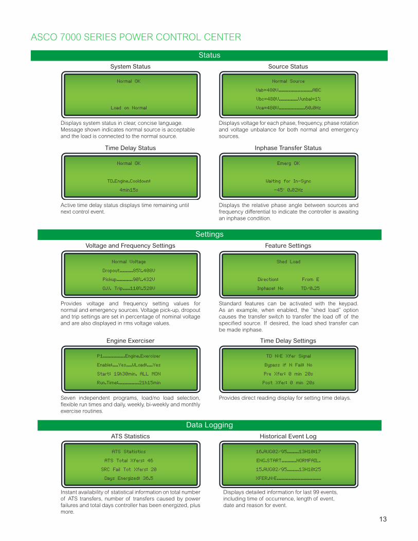
Displays system status in clear, concise language. Message shown indicates normal source is acceptable and the load is connected to the normal source.
Provides voltage and frequency setting values for normal and emergency sources. Voltage pick-up, dropout and trip settings are set in percentage of nominal voltage and are also displayed in rms voltage values.
Instant availability of statistical information on total number of ATS transfers, number of transfers caused by power failures and total days controller has been energized, plus more.
Active time delay status displays time remaining until next control event.
Seven independent programs, load/no load selection, flexible run times and daily, weekly, bi-weekly and monthly exercise routines.
Displays voltage for each phase, frequency, phase rotation and voltage unbalance for both normal and emergency sources.
Displays detailed information for last 99 events, including time of occurrence, length of event, date and reason for event.
Displays the relative phase angle between sources and frequency differential to indicate the controller is awaiting an inphase condition.
Source Status
Historical Event Log
Inphase Transfer Status
Normal OK
Load on Normal
Normal Voltage
Dropout.........85%.408V
Pickup...........90%.432V
O.V. Trip.....110%.528V
ATS Statistics
ATS Total Xfers: 46
SRC Fail Tot Xfers: 20
Days Energized: 36.5
Normal OK
TD.Engine.Cooldown:
4min15s
P1...............Engine.Exerciser
Enable:....Yes....WLoad:....Yes
Start: 19h30min. ALL MON
Run.Time:..............21h15min
Normal Source
Vab=480V.......................ABC
Vbc=480V.............Vunbal=1%
Vca=480V..................60.0Hz
Provides direct reading display for setting time delays.
Time Delay Settings
TD N>E Xfer Signal
Bypass if N Fail: No
Pre Xfer: 0 min 20s
Post Xfer: 0 min 20s
16.AUG02/95........13H10:17
ENG.START..........NORMFAIL.
15.AUG02/95........13H10:25
XFER.N>E..............................
Emerg OK
Waiting for In-Sync
-45° 0.02Hz
Standard features can be activated with the keypad. As an example, when enabled, the “shed load” option causes the transfer switch to transfer the load off of the specified source. If desired, the load shed transfer can be made inphase.
Feature Settings
Shed Load
Direction: From E
Inphase: No TD/0.25
13

ASCO 7000 SERIES USER CONTROLS AND INDICATORS
Control Switches and Indicating Lights
• Switch position indicating lights (16 mm, industrial grade LEDs).
• Source acceptability indicating lights with true indication of the acceptability of each source, as determined by the voltage, frequency, voltage unbalance, and phase sequence settings of the control panel (16mm, industrial grade LEDs).
• Three position (16mm, industrial grade type) selector switch:• Automatic: Normal maintained position.• Test: Momentary position to simulate normal
source failure for system test function.• Reset Delay Bypass: Momentary position to
bypass transfer and re-transfer time delay.
Control Switches and Indicating Lights for Closed Transition Switches
• Extended Parallel Time - Provides visual indication when the pre-set extended parallel time has been exceeded. The controls automatically open the emergency or normal main contacts. Separate contact also available to shunt trip external breaker.
• Failure To Synchronize - Visually displays a failure to synchronize alarm if the time delay settings are exceeded during closed transition transfer operation.
• TS Locked Out - Prevents transfer in either direction if the extended parallel time is exceeded.
• Alarm Reset - Resets extended parallel and failure to synchronize alarms.
• Closed Transition Bypass - Pushbutton allows transfer between sources in an open transition mode.
Fig. 16: 7000 SERIES User Controls and Indicators.
Fig. 17: 7000 SERIES User Controls and Indicators.
ASCO 7000 SERIES OPTIONAL ACCESSORIES
Time Delays and Extended Control Power
Manual Controls for Automatic Transfer Switches
2C Provides an extended time delay on engine starting. The standard feature one-time delay is adjustable from 0 to 6 seconds. Accessory 2C allows this time delay to be adjustable from 0 to 60 minutes in one-second intervals; factory set at 5 minutes.
1G1 Similar to accessory 2C except using 24 volt DC external input signal. Controls, metering and communication remain remains active when both power sources are de-energized.
1GB1 Same as accessory 1G1 except using 120 volt AC external input.
1PS1 Extended control power ride-through (approx. 25 seconds) for Group 5 ATS controller and select communications and metering accessories, e.g. Acc. 72EE2, 72FC, 135L, etc.
6C Reset switch for manual retransfer to normal with automatic retransfer in the event of emergency source failure.
6D Selector switch for automatic/manual retransfer to normal. Automatic bypass if emergency fails.
14

Extension Harness37B Six foot (6’) extension harness to increase distance between transfer switch and control panel on open-type units.
Indicators14A/ 14B
Additional auxiliary contact sets to indicate switch position. Two sets are standard. Specify total number of sets if more are required.
18B Two-pole, double-throw contacts operate when emergency source voltage is present at transfer switch terminals.
18G Two-pole, double-throw contacts operate when normal source voltage is present at transfer switch terminals.
99 “Push-to-Test” feature on all pilot light indicators.
Customer Control Circuits30A Load-shedding circuit initiated by opening of a customer-supplied contact.
30B* Load-shedding circuit initiated by removal of customer-supplied control voltage. *(Specify voltage).
31Z Selective load disconnect control contacts (two provided) that operate with time delay prior to and/or after load transfer and retransfer.
43R Terminal block for all customer control connections on 30 to 150 amp models only (standard on all other sizes).
Note: For ordering information, see the ASCO 7000 Series Power Transfer Switch Dimensional Data and Shipping Weights (ASCO Publication No. 3040 DW)
Communications107G Provides Building Monitoring Systems with transfer switch, bypass and load power metering information in Modbus
TCP/IP, BACnet IP and SNMP Protocols. Compatible with any Accessory 150 Technology Package or 72EE2.
72EE2 Offers remote Ethernet monitoring via open Mod bus and SNMP protocols, email notifications and embedded monitoring web pages. (Catalog No. 5170 for stand alone product).
Neutral Conductor Options• Solid neutral, with fully-rated terminals. (AL-CU) UL Listed.
• Conventional neutral switching pole.
• Overlapping neutral transfer contacts. Allows for proper ground-fault sensing and avoids generator voltage transients during transfer.
Special Applications45 Custom Alphanumeric nameplate mounted on the front of the switch
111A Generator - to - Generator for Standby Applications
111B Generator - to - Generator for Prime Power Applications
125A Seismic Certification to the requirements of the International Building Code for electrical equipment
131 Certification of compliance with the American Recovery & Reinvestment Act (Buy American Provision) - Must be specified at time of order placement
Bypass-Isolation switch Options14A1 Auxiliary contact to close in “Bypass to Normal” position.
14B1 Auxiliary contact to close in “Bypass to Emergency” position.
14T Auxiliary contact to close when transfer switch is in “Automatic” position.
14U Auxiliary contact to close when transfer switch is in “Isolate” position.
14V Auxiliary contact to close when transfer switch is in “Test” position.
82C Automatic shutters for bus isolation when transfer switch is withdrawn. (See page 6 for details)
82E LED Bypass status indicator, optional on G frame 1600 to 4000 amps only. Standard for all other size switches.
Surge ProtectionASCO 510 TVSS, rated 65KA
73AC1 Normal source protection. (3Ø, 4wire WYE)
73AC2 Emergency source protection. (3Ø, 4wire WYE)
73AC3 Load side protection. (3Ø, 4wire WYE)Note: Other distribution voltages and kA ratings available (Contact ASCO).
15

Technology Packages are the easiest way to locally and remotely manage your critical power transfer switch and bypass switch.
Local Graphical Color Touch Interface
4-Week Historical Trending Power & Energy Usage Events Log (1,000 Events)
Accessory 150BT Technology Package on a 7000 SerieS Bypass Transfer Switch.
ASCO TOUCH DISPLAY INTERFACE TECHNOLOGY PACKAGE
The Touch Display Interface (TDI) is the best way to comprehensively connect to and manage your power transfer switch. The TDI enables you to centrally monitor, control and log the performance of transfer and bypass switches and power meters from a single device. It provides you with quick access to real-time information and historical event logs needed to increase the reliability, efficiency, and regulatory compliance of your power system.
Technology Package Options1
Included MeterStandard Tech Package Tech Package with Touch Display Interface
For ATS For ATB For ATS For ATB
5210 Power Meter 150A 150B 150AT 150BT
5410 Power Quality Meter 150A1 150B1 150AT12 150BT12
5450 Power Quality Meter 150A2 150B2 150AT22 150BT22
5490 Power Quality Meter 150A3 150B3 150AT32 150BT32
Notes1. All Technology Packages includes Acc. 1PS1, 72EE2, Meter of choice, CTs, Shorting Blocks and Bypass Status Monitoring via discrete
I/O when necessary.2. Contact for availability.
16

ASCO MONITORING GATEWAY ACCESSORIES
The Monitoring Gateway (Accessory 107G) monitors the state and performance of your transfer switch and its associated devices, including engine-generators, utility power quality meters, surge protection devices, and circuit breakers. The Monitoring Gateway simplifies the NFPA 110 fire code and Joint Commission compliance and reporting activities required for critical and healthcare facilities. It is compatible with Building Monitoring Systems, sharing data in open Modbus TCP/IP and BACnet IP formats.
POWERQUEST
Power Monitoring & Control
Utility
Client PC107G Interface*
Generator
SERIES 500Surge Protection Device
Accessory 107G(Requires any 150 Tech Package)
4000 SERIESLoad Bank
5200 PowerMeter
5400 PowerQuality Meter
Meets NFPA and Joint Commission Compliance requirements
Provides required engine-generator and transfer switch safety indicators and shutdowns. Automatically gen-erates NFPA test and utility outage reports. Listed to UL 1008.
Gain real-time status and performance insights
Provides instant access to critical utility power, engine-generator, transfer switch, surge protection and load bank information. Transmits immediate email and text alerts of alarm and event conditions.
Integrates with common building monitoring systems and the ASCO Critical Power Management System
Shares power system data with other monitoring systems, allowing greater analysis of operating data and faster response to changing conditions.
17

Name: ATS-LS1Location: Basement
ASCO QUAD-ETHERNET MODULE ACCESSORIES
Quad-Ethernet ModuleAccessory 72EE2
To: John
Transferred from Emergency to Normal
Date Time: 12/23/1609:51:55
12/23/15 9:51 PMASCO ATS Alert
9:52<
Monitoring
• Engine-generator, utility, and transfer switch status
• Email Notification• Alarms and Alerts• Statistics and Activity• Event Log (downloadable)• Controller Setpoints• Power Monitoring*• Energy Consumption*• Historical KW Demand*
*Accessory 150A or 150B
Control
• Engine Start/Stop• ATS Transfer/Retransfer• Generator Test• Bypass Timer Delays
Communicate
• Modbus• SNMP• SMTP Advanced Encryption
Standard• Four Port Ethernet Switch• RS485 Port
Ordering
Catalog Number 5170
Catalog Name Quad-Ethernet Module
Transfer Switch Accessory 72EE2
ATS Tech Package 150A for Non-Bypass
ATB Tech Package 150B for Bypass
Part Number for Kit K1106217-001
Ports
Ethernet
Number of Ports 4
Type of Ports RJ45, 10/100 BaseTX
Protocol Modbus, SMTP, SNMP
RS485
Number of Ports 1
Type of Connection 2-Wire or 4-Wire
Protocol Modbus
Ordering and Specifications Information
The Quad-Ethernet Module is the easiest way to connect, monitor and control your power transfer switch, utility power and engine-generator. Through the web app, you can monitor power conditions, start your engine-generator, and transfer between power sources.
18

ASCO ENERGY AND POWER METERS
5400 SERIES Power Quality Meter5210 Power Meter
Transfer Switch Bypass Transfer Switch Transfer Switch Bypass
Transfer Switch Transfer Switch Bypass Transfer Switch Transfer Switch Bypass
Transfer Switch
Technology Packages 150A 150B 150A1 150B1 150A2 150B2 150A3 150B3
Meter Accessories 135L 135SB 140L 140B 140LS 140SB 140LX 140XB
Meter Catalog Number 5210 5410 5450 5490
Energy and Power
Measurements
Power factor (total), Apparent power (total), Active and reactive power (total), Active and reactive power (per
phase, rms), Apparent power (per phase, rms), Power factor (per phase, rms), Voltage, Current, Frequency
Power Quality Analysis Total harmonics distortion
Continuous waveform recording, harmonics, inter-harmonics, voltage sag and swell
detection, unbalanced components (zero, negative, positive), flicker, fast flickering,
crest factor, K-factor
Power Quality Analytics
SoftwareNo Yes (Acc. 107G) Yes (Acc. 107G) Yes (Acc. 107G)
Web-page interface Yes Yes Yes Yes
Communications Protocol Modbus TCP/IP, SNMP Modbus TCP/IP Modbus TCP/IP Modbus TCP/IP
BACnet IP Protocol Yes (Acc. 107G) Yes (Acc. 107G) Yes (Acc. 107G) Yes (Acc. 107G)
Sampling Rate (samples per
cycle) 32 256 512 1024
Voltage Harmonics 15th 127th 255th 511th
Internal Memory 128KB 128MB 4GB 16GB
Transient Detection at
60/50HzNo 65.1 / 78.1us 32.5 / 39 us 16.3 / 19.5 us
NTP Time Synchronization Yes (Acc. 107G) Yes Yes Yes
Digital Inputs / Outputs - - 8 / 4 16 / 8
Analog Inputs / Outputs - - 4 / 4 8 / 8
Form-C Relay Contacts - - 3 6
19

ASCO ATS REMOTE ANNUNCIATORS
5705 8-Device Annunciator
Cat. 5310 Cat. 5705
Cat. 5350
Description 5350 8-ATS Annunciator 5705 8-Device Annunciator
Listed to UL 1008 Yes Yes
NIST Compliant Security AES 128-bit Encryption AES 128-bit Encryption
Monitoring Interface LED Graphical Touchscreen
ATS SupportedUp to 8(5310, 1-ATS)
Up to 8
Transfer and Engine-Start Control Yes Yes
Transfer Switch Monitoring Transfer Switch Position, Source Availability, Time-Delay Active, Communications Status, Locked Out, Fail-to-Synchronize, Extended Parallel
NFPA 110 Engine-Generator Safety Indicators and Shutdowns
No Yes, any generator with ASCO 5212 PMU
Surge Protective Devices NoASCO SERIES 500 and 400 with Active Surge Monitoring
Load Bank NoASCO Avtron 5000 and 4000 SERIESwith Accessory 150LB
Email Notification No Yes
Audible Alarm Yes Yes
Mounting Wall or Flush-mounted Wall-mounted
Common Alarm Output Yes Yes
Control Security Key Lock Multi-Level Password
Control Power 24VDC or 120VAC 24VDC or 120VA
Ethernet Ports 2 2
Power-outage ride-through (seconds) 0.1 60
ATS accessory requiredAny ASCO Accessory 150 Technology Package or Accessory 72EE2
Any ASCO Accessory 150 Technology Package
5350 8-ATS Annunciator
20

With the ASCO PowerQuest® CPMS, you can
• Understand power system and equipment status throughout a facility• Quickly identify and resolve alarms to reduce downtime risk and increase reliability• Monitor KW capacity and demand at any point in the distribution system• Automatically generate outage reports for NFPA and Joint Commission compliance • Ensure power quality compliance to increase the service life of business critical equipment and devices• Leverage existing network infrastructure and add existing legacy equipment• Analyze comprehensive forensic power quality and sequence of event data in millisecond granularity• Identify utility energy usage and demand billing discrepancies • Reduce or eliminate power factor and demand penalties• Monitor, benchmark and increase energy efficiency• Allocate energy costs to departments or processes
5710 5750 5790
Hardware Server+22-inch Touchscreen Server+22-inch Touchscreen Server+22 inch-Touchscreen
Number of Equipment Monitored 32 64 1281
Remote Clients Support 3 10 251
Monitoring & Control P P PEmail Notification P P PBMS Communications P P PSystem Event Log P PHistorical Trending P PAutomated Reports P PPower Quality Meter Analytics P P PReference Library P PRedundant Storage P
ASCO 5700 CRITICAL POWER MANAGEMENT SYSTEM
System Overview
5700 SerieS Server with TouchscreenAutomated Outage
and NFPA Compliance Reports
Dynamic One Line (Engineering Services Option)
Alarm Dashboards
1 Consult ASCO for engineered dashboards, additional equipment or clients.
Critical Facility, Power and Energy Management
The PowerQuest Critical Power Management System (CPMS) enables you to centrally manage your critical infrastructure and increase its reliability, efficiency, and regulatory compliance.
21

ASCO Power Technologies - Global Headquarters160 Park AvenueFlorham Park, NJ 07932Tel: 800 800 ASCO
© 2019 ASCO Power Technologies. All Rights Reserved. Life Is On Schneider Electric is a trademark and the property of Schneider Electric SE, its subsidiaries and affiliated companies. Publication 3040 R17. Printed in the U.S.A.