asco 7000 series power transfer switch world … · world class technology for business critical...
TRANSCRIPT
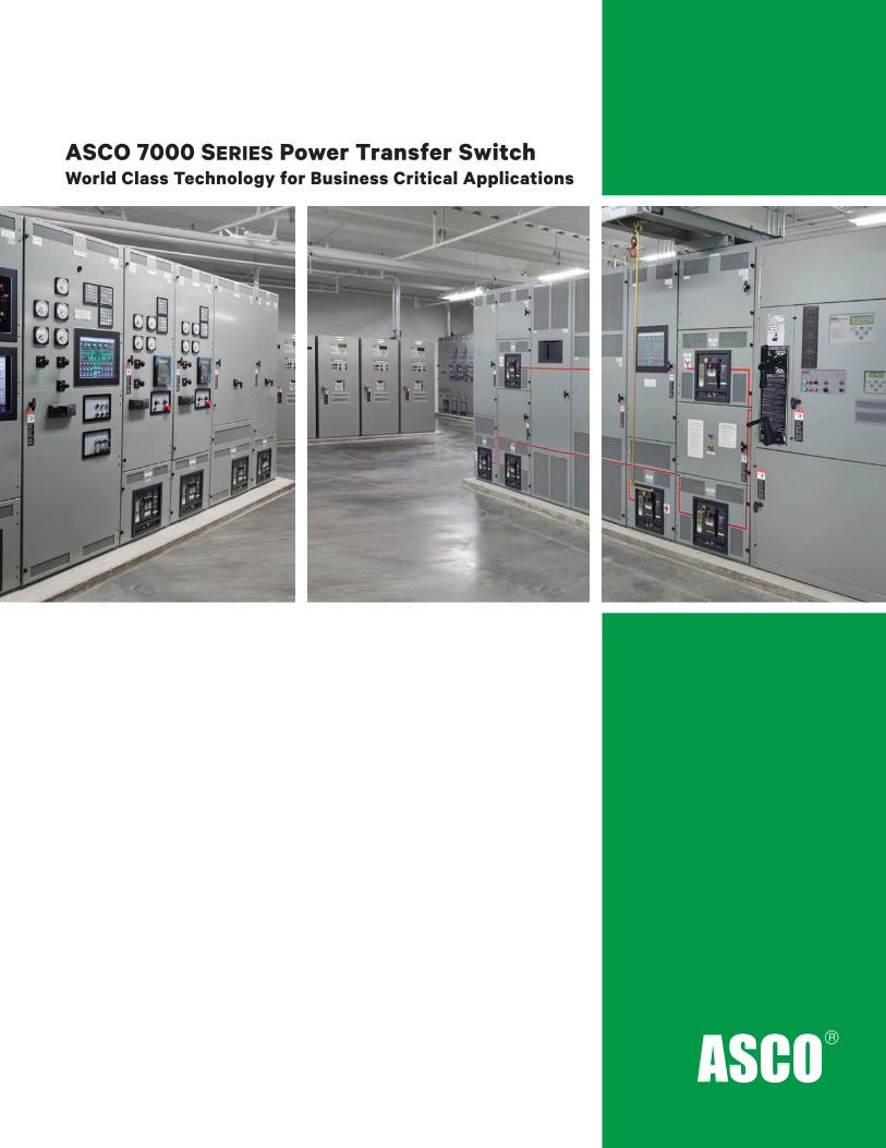
ASCO 7000 SERIES Power Transfer SwitchWorld Class Technology for Business Critical Applications
SELECTING BUSINESS-CRITICAL POWER TRANSFER SWITCHES
It’s time to rediscover performance benchmarks and design innovations that separate power transfer switches
Life safety, financial loss, productivity, valuable information and convenience all are at stake when power fails. Time is money, so time without power is unacceptable because it can cripple an organization’s operations. No matter what type of power source is selected for backup power protection, a reliable electrical device is needed to automatically sense the unacceptability of the primary power source and transfer the load to the secondary.
Although the backup power source may be functional only when the primary source fails, the transfer switch is the only link between the two power sources. So the automatic transfer switch is the “brain” of the power distribution system and is always carrying power to crucial loads, regardless of which power source is feeding the load.
Because so much hangs in the balance, there is no room for error. Making the right decision is the only option. But what decision is the right one? That depends on a number of factors. All transfer switches are not created equally. There are important differences that need to be weighed and new sophisticated power transfer switch technology that requires consideration. Even if you feel you are up to speed on transfer switches, it’s time to look again because the stakes are so high. Be certain you are making the right decision on such a criticalmatter as emergency and standby power. Then have peace of mind knowing you selected the best products in the industry to protect a facility.
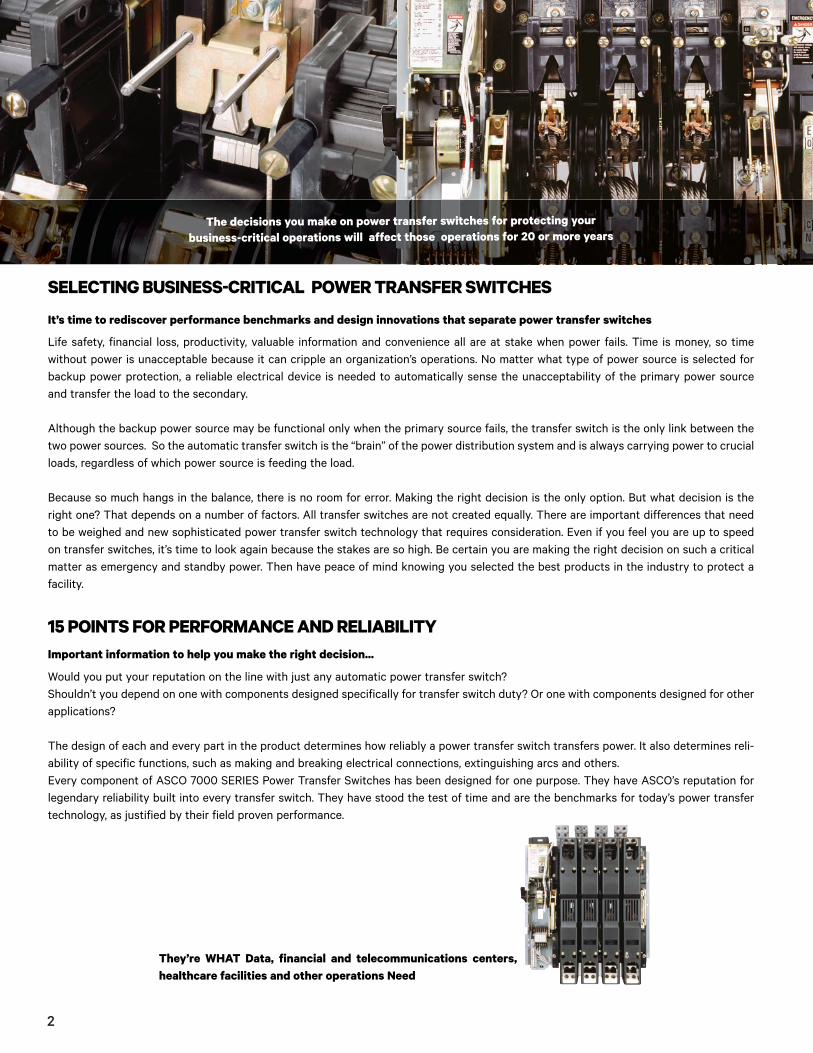
The decisions you make on power transfer switches for protecting your business-critical operations will affect those operations for 20 or more years
15 POINTS FOR PERFORMANCE AND RELIABILITY
Would you put your reputation on the line with just any automatic power transfer switch? Shouldn’t you depend on one with components designed specifically for transfer switch duty? Or one with components designed for other applications?
The design of each and every part in the product determines how reliably a power transfer switch transfers power. It also determines reli-ability of specific functions, such as making and breaking electrical connections, extinguishing arcs and others. Every component of ASCO 7000 SERIES Power Transfer Switches has been designed for one purpose. They have ASCO’s reputation for legendary reliability built into every transfer switch. They have stood the test of time and are the benchmarks for today’s power transfer technology, as justified by their field proven performance.
Important information to help you make the right decision...
They’re WHAT Data, financial and telecommunications centers, healthcare facilities and other operations Need
2

Fifteen points of differentiation separate superior power transfer switches from all others. The points are:
• Providing fast, consistent and dependable power transfer
• Preserving power contact integrity and performance
• Extinguishing arcs safely and quickly
• Withstanding and closing on fault currents
• Providing a range of times for short circuit ratings which are compatible with typical overcurrent devices
• Overlapping switched neutral poles
• Designing quality and dependable components intelligently
• Controlling operation
• Transferring motor loads without abnormal inrush currents
• Providing the connection strategy for the needs of the load
— Open Transition Transfer
– In phase
– Delayed transition
— Closed Transition Transfer
– High speed transfer
– Soft Load transition
• Meeting or exceeding minimum code requirements
• Meeting IBC’s short time response testing levels of 2.5 Sds or greater
• Capitalizing on innovative technology.
• Employing remote communications capability
• Providing 24/7 service and maintenance
Every component and assembly, such as the transfer switch assembly on the left, has been designed exclusively for automatic power transfer switch duty.
RELIABLE POWER TRANSFER SWITCH OPERATION
When power fails, business continuity depends on automatic transfer switches to operate as designed. Equipment must react in fractions of an electrical cycle because there’s no room for error when data centers, hospitals and other mission-critical businesses demand continu-ous power.
Designing and manufacturing reliability into ASCO power transfer switches is part of ASCO’s legacy of innovation. Whether it’s Closed Transition Transfer Switching, Bypass-Isolation or other ASCO developments in automatic transfer, ensuring reliability is part of the process. Component design, exhaustive testing, quality manufacturing and proper service procedures all contribute to reliable operation. Mean Time Between Failure (MTBF) for automatic transfer switches can be as much as 1.5 million hours. One reason is optimized electro-mechanical design that is inherently simple, compared to electronic switching, and proven through nearly a century of field experience. Molded part construction, for example, has reduced the number of parts, reduced sized, enhanced dimensional precision and minimized failure points.
Improved materials have further optimized reliability. Finally, proper service procedures are essential to extend MTBF and ensure that transfer switches operate when needed.
The combination of ASCO Technology, Support and Service give ASCO automatic transfer switches the reliability that mission-critical applications demand to help ensure business continuity.
3

TRANSFERRING POWER
The heart of all ASCO transfer switches is the solenoid operator, unique in the transfer switch industry. Time and again, it provides
repeatable, fast, true double-throw operation.
The operator has a proven track record for simplicity, dependability and easy maintainability because it has no motors, gears or
complicated mechanisms.
Its design ensures that loads will never be unintentionally transferred to a dead or inadequate source as the solenoid is powered from the
source to which the load is being transferred. The positive interlocking design helps keep the main contacts closed during short circuit
conditions. The true, double throw design ensures crucial loads are not connected to both power sources at the same time.
Importantly, the solenoid is never fused as some operators are. Fusing can render the transfer switch inoperable, an obviously undesirable
feature for use in emergency and legally required standby systems.
Requires a dependable mechanism.
ASCO designed and commercialized the first solenoid operated transfer switch.
ASCO-designed segmented contacts
4

PRESERVING CONTACT INTEGRITY AND PERFORMANCEBetween dissimilar power sources.
Transfer switches are responsible for transferring loads between
dissimilar power sources that could be as much as 180° apart.
ASCO transfer switches manage this task with contacts designed
specifically for transfer switch duty by ASCO engineers.
The contacts are not adapted from other devices, such as circuit
breakers, contactors or motor starters. This dedicated design
approach has produced a contact that solves the special demands
of transferring critical loads reliably time after time. Main contact
composition is specifically selected from a silver alloy. The alloy
provides optimum contact integrity, high conductivity to the main
contacts, and endurance to carry the full load continuously and
still be capable of enduring damaging overloads and short circuit
currents. The alloy also prevents excessive temperature rise that
can deteriorate insulation and cause a breakdown.
Separate arcing contacts on transfer switches rated 800 Amps
and larger protect the main contacts from arcing’s damaging
effects by making first and breaking last. Smaller transfer switches
are designed with arc runners and arcing tips to preserve main
contact surface integrity. Segmented main contacts are part
of larger transfer switches for business-critical applications.
Segmented contacts provide multiple points to ensure ample con-
tact surface area and to minimize heat rise. Contacts designed for
dedicated transfer switch duty provide long-term, reliable opera-
tion. This has been field proven by the hundreds of thousands of
ASCO transfer switch products provided for installation in emer-
gency and standby power systems.
ASCO-designed segmented contacts
EXTINGUISHING ARCS
Prevents direct, source-to-source shorting.
Arcs created when transferring loads from one source to another
can be catastrophic for transfer switches and their loads
Heat damage to contacts is one problem. Another is direct,
source-to-source shorting if the arc is not extinguished before
the switch closes in on the alternate source. This source-to-
source short circuit can totally destroy transfer switch integrity .
ASCO power transfer switches extinguish arcs using an arc
chute assembly specially designed for double-throw operation.
The design moves the arc away from the main contacts quickly
and safely by pulling it up into the chute assembly plates with
magnetic force created by the current flow through the transfer
switch pole structure. This also stretches and cools the arc, mini-
mizing heat damage.
Since many installations typically have lightly loaded transfer
switches, consideration also must be provided for extinguishing
arcs at reduced load currents. ASCO has the industry’s widest
arc gap between fully opened contacts. A wide gap maintains the
transfer switch’s low-connect interrupting effectiveness when it
is lightly loaded and magnetic forces are not as strong.
Transfer switches using contacts designed for other devices,
such as circuit breakers, have narrower gaps, since they are
designed for interrupting currents in excess of their full load,
continuous current rating (not below their rating).
Finite element analysis and 3-D computer models (left) create components that are specifically designed for transfer switch duty. Durability and reliability are built in. See page 27 for more informa-tion on ASCO design innovations.
ASCO arc splitters
5
WITHSTANDING AND CLOSING ON SHORT CIRCUIT FAULT CURRENTS
Withstanding and closing on short circuit currents require transfer switches that can handle extremely high electromagnetic forces and thermal stresses. Circuit breakers and fuses are designed to open on short circuit currents. However, while transfer switches must withstand a short circuit current until the over-current device clears the fault.
The withstand and closing rating (WCR) indicates the highest level of current a transfer switch can close on and carry for a specific amount of time. For system coordination purposes, the time needs to be sufficient for the upstream over-current protective device to clear the fault. The WCR must equal or exceed the available fault current and system voltage at the power source terminals of the switch.
The purpose of a power transfer switch is to maintain power to the load, whereas an overcurrent device is designed to open under a fault condition to protect the circuit conductors and equipment. ASCO power transfer switches use a unique solenoid operator design to force and lock the main contacts closed on a high current fault, rather than allowing them to open like a circuit breaker.
Main contact material composition, contact geometry, arcing contact design, and other features all affect the ability of the power transfer switch to withstand and close-on high fault currents. ASCO employs a variety of computer modeling programs to determine the optimal combination of all these elements to create a superior transfer switch design.
ASCO power transfer switches are available with a full range of WCRs to accommodate a variety of over-current devices with fault-clearing times from 0.004 to 0.5 seconds (1/4 to 30 cycles). In fact, ASCO transfer switches provide the industry’s most comprehen-sive solution for all short circuit requirements. Our comprehensive 7000 SERIES WCR table addresses all time-based, specific breaker,current-limiting fuse, and short-time ratings necessary for accommodating selective coordination requirements.
In order to meet NEC selective coordination requirements, short-time settings are specified on circuit breakers following a coordination study. A circuit breaker’s short-time settings require transfer switches to withstand and close-on short circuit currents for time durations of 0.1 seconds (6 cycles for a 60Hz system) or longer. The 4th Edition of UL 1008 added this optional “Short-Time Rating” for transfer switches in 2002. Underwriters Laboratories does not require a specific time or specific number of cycles to qualify for this rating,but the transfer switch WCRs must coordinate with the short-time settings on the breakers.
While there are no ideal time delay breaker settings for selective coordination, many engineers have been successful with using 0.3seconds (18 cycles) for the most upstream breaker short-time settings. However, 0.5 second (30-cycle) settings may be required for larger projects with multiple levels of distribution breakers or where transfer switches are served by ANSI switchgear with 30-cycle withstand ratings.
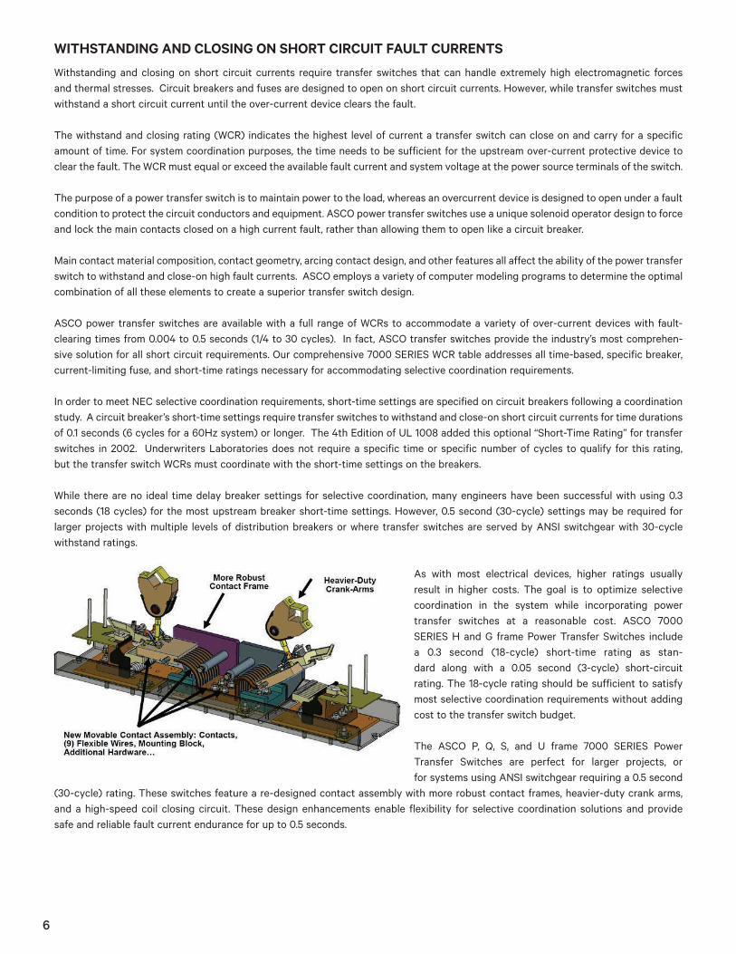
As with most electrical devices, higher ratings usually result in higher costs. The goal is to optimize selective coordination in the system while incorporating power transfer switches at a reasonable cost. ASCO 7000 SERIES H and G frame Power Transfer Switches includea 0.3 second (18-cycle) short-time rating as stan-dard along with a 0.05 second (3-cycle) short-circuitrating. The 18-cycle rating should be sufficient to satisfy most selective coordination requirements without addingcost to the transfer switch budget.
The ASCO P, Q, S, and U frame 7000 SERIES Power Transfer Switches are perfect for larger projects, orfor systems using ANSI switchgear requiring a 0.5 second
(30-cycle) rating. These switches feature a re-designed contact assembly with more robust contact frames, heavier-duty crank arms, and a high-speed coil closing circuit. These design enhancements enable flexibility for selective coordination solutions and providesafe and reliable fault current endurance for up to 0.5 seconds.
6

ASCO Power Transfer Switches:
• Achieved industry first 3-cycle rating
• Qualified 18-cycle performance on core 3-cycle switch, another industry first
• Satisfy the demands of unique applications with a 30-cycle option truly optimize selective coordination for what the application requires (typically an 18-cycle transfer switch)
• Provide a cost effective solution by utilizing 3 to 18 cycle ratings
• Are certified to the latest edition of UL 1008 short circuit testing requirements
PROVIDING A RANGE OF TIMES FOR SHORT CIRCUIT RATINGSFor proper selective coordination.The WCR rating of an Automatic Transfer Switch is its ability to withstand and close-on short circuit currents with a specific type of over-current device, or for finite period of time. The time based ratings for ASCO Power Transfer Switches are 0.05-0.3 and 0.5 sec, which is 3 - 18, and 30 cycles for 60 Hz systems.
While there are no ideal time delay settings for selectively coordinating the overcurrent devices in a distribution system, engineers generally specify short time increments between trip settings or expected trip times. In fact, one consulting engineering firm selects 3 cycle (0.05 secs) trip times increments for the majority of transfer switches it specifies.
They specify 30-cycle switches only for larger projects, where the fault current on the emergency system is high, where the breaker instantaneous trip setting is defeated in order to selectively, or where transfer switches are served by ANSI Switchgear, which also has 30-cycle withstand ratings. The consensus among engineers is if the design settings for upstream over-current protective devices are 3, 6, 9, 12, or 18 cycles, there is no reason to specify all 30 cycle rated transfer switches.
Also, Underwriters Laboratories does not require a specific time or specific number of cycles to qualify for “short time” ratings (appli-cable to WCR values of 6 cycles or 0.1 seconds or more), though it does provide standard recommended values. What matters is the calculated available fault current at that point in the system, and the ability to clear the fault as fast as possible while maintaining coordination. Optimizing selective coordination systems by utilizing fast fault clearing times with power transfer switches coordinates over-current protection at reasonable cost.
Of course, situations vary absolutely from place to place, building to building, design to design, and utility company to utility company. Considering the custom nature of selective coordination, specifying only what’s necessary, what more precisely satisfies requirements, is the better decision. The accompanying chart illustrates the breadth and depth of withstand and close-on ratings across the family of ASCO Automatic Transfer Switches, based on ampere ratings and cycle times.
Ampere Rating WCR (kA) at 480V Cycles 3 18 30P 600-800 50 36 30
S 600-1200 100 65 65
Q 600-1600 65 50 50
S 1600-2000 100 85 65
U 2600-4000 125* 100 100
*60 mSec (3.6 Cycles) actual test duration
7
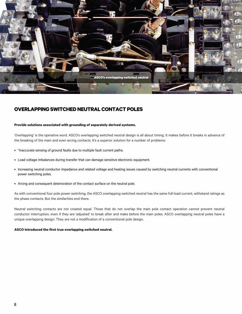
OVERLAPPING SWITCHED NEUTRAL CONTACT POLES
Provide solutions associated with grounding of separately derived systems.
‘Overlapping’ is the operative word. ASCO’s overlapping switched neutral design is all about timing. It makes before it breaks in advance of the breaking of the main and even arcing contacts. It’s a superior solution for a number of problems:
• “Inaccurate sensing of ground faults due to multiple fault current paths.
• Load voltage imbalances during transfer that can damage sensitive electronic equipment.
• Increasing neutral conductor impedance and related voltage and heating issues caused by switching neutral currents with conventional power switching poles.
• Arcing and consequent deterioration of the contact surface on the neutral pole.
As with conventional four pole power switching, the ASCO overlapping switched neutral has the same full-load current, withstand ratings as the phase contacts. But the similarities end there.
Neutral switching contacts are not created equal. Those that do not overlap the main pole contact operation cannot prevent neutralconductor interruption, even if they are ‘adjusted’ to break after and make before the main poles. ASCO overlapping neutral poles have a unique overlapping design. They are not a modification of a conventional pole design.
ASCO introduced the first true overlapping switched neutral.
ASCO’s overlapping switched neutral
8

ASCO’s overlapping switched neutral
DESIGNING QUALITY, DEPENDABLE COMPONENTS INTELLIGENTLY
Simplifies installation, maintenance and testing.
Designing transfer switches from the ground up has enabled ASCO to engineer them for ease of installation, maintenance and testing. All key components, for example, can be inspected or replaced from the front of the enclosure.
Crimp lugs, which are frequently specified for data centers where heat build up may be an issue, have a long barrel and two holes toprevent lugs from turning. They can be arranged in a variety of configurations, depending on point of access and cabling requirements. Mostspecial lug arrangements that typically may require a larger enclosure for other transfer switches usually can be housed in the standard ASCO enclosure.
Front-replaceable main contact assemblies represent another industry-setting benchmark. Transfer switches rated 800 Amps and above facilitate maintenance of the main and arcing contacts, without disassembling or removing the transfer switch from the enclosure.In addition, a block of eight sets of auxiliary contacts, to indicate transfer switch position, now are standard on most ASCO 7000 transfer switches.
Increasing use of molded parts continues to help produce a more robust transfer switch. Their closer tolerances, increased strength and improved dimensional control combine to enhance quality and reliability, and simplify maintenance. Cutouts in a molded pole cover, for example, allow access to lug screws, eliminating the need to remove the pole covers during cable installation. Visual mechanical switchposition indicators inside the enclosure help facilitate maintenance operations when the power is shut off for safety reasons.
9
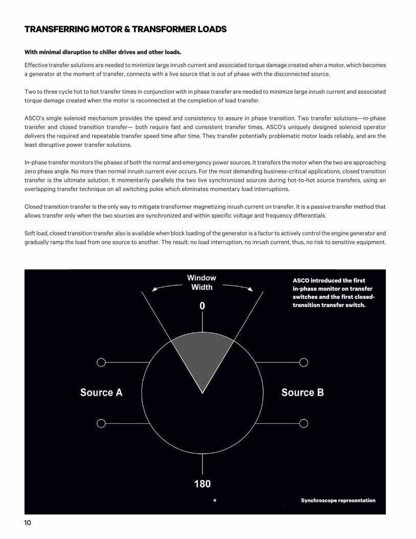
Synchroscope representation
TRANSFERRING MOTOR & TRANSFORMER LOADS
With minimal disruption to chiller drives and other loads.
Effective transfer solutions are needed to minimize large inrush current and associated torque damage created when a motor, which becomes a generator at the moment of transfer, connects with a live source that is out of phase with the disconnected source.
Two to three cycle hot to hot transfer times in conjunction with in phase transfer are needed to minimize large inrush current and associated torque damage created when the motor is reconnected at the completion of load transfer.
ASCO’s single solenoid mechanism provides the speed and consistency to assure in phase transition. Two transfer solutions—in-phase transfer and closed transition transfer— both require fast and consistent transfer times. ASCO’s uniquely designed solenoid operator delivers the required and repeatable transfer speed time after time. They transfer potentially problematic motor loads reliably, and are the least disruptive power transfer solutions.
In-phase transfer monitors the phases of both the normal and emergency power sources. It transfers the motor when the two are approaching zero phase angle. No more than normal inrush current ever occurs. For the most demanding business-critical applications, closed transition transfer is the ultimate solution. It momentarily parallels the two live synchronized sources during hot-to-hot source transfers, using an overlapping transfer technique on all switching poles which eliminates momentary load interruptions.
Closed transition transfer is the only way to mitigate transformer magnetizing inrush current on transfer. It is a passive transfer method that allows transfer only when the two sources are synchronized and within specific voltage and frequency differentials.
Soft load, closed transition transfer also is available when block loading of the generator is a factor to actively control the engine generator and gradually ramp the load from one source to another. The result: no load interruption, no inrush current, thus, no risk to sensitive equipment.
ASCO introduced the first in-phase monitor on transfer switches and the first closed-transition transfer switch.
o
10

SELECTING AUTOMATIC TRANSFER SWITCHES
Based on your need to:
• Transfer crucial loads safely, reliably and seamlessly
• Ease loads from one power source to another
• Have complete power transfer monitoring and control
• Get ultimate power protection
• Manage single utility feeds and emergency power
• Ensure continuous power by using alternate power sources
What do you need in business critical power transfer and load management? Emergency Power to Your Loads? Peak Shaving? Prime Power? Load Prioritization? ASCO 7000 SERIES Automatic Transfer Switches can satisfy your business-critical requirements...whatever they are.
Select standard design, business-critical or highly custom engineered power transfer solutions.
Review the capabilities of the transfer switches on the following pages, then discuss with us which of them best meets your onsite power system requirements.
The power is in your hands.
ASCO has installed more than 600,000 automatic transfer switches worldwide. No other manufacturer comes close.
11
A closed transition transfer switch (CTTS) operates in a make-before-break mode, providing both sources are acceptable and insynchronism. If the connected source is unacceptable, power transfer will occur in conventional non-overlap mode, or open transitiontransfer. For CTTS, most utilities accept 100 milliseconds (msec) as the maximum overlap time during transfer. Typically, the ASCO CTTSdoesn’t exceed 50 to 80 msec.
Prior to transfer in either direction, both sources are monitored by the CTTS, and, if the voltage difference is less than five percentand the frequency variation less than 0.2 Hz, the relative phase angle is monitored. When the phase angle difference approaches withinfive electrical degrees, the switch operates, a momentary overlap occurs, and the load transfers with virtually zero interruption. The presence of critical loads generally dictates the use of an isochronous governor, because the engine generator output frequency should remain virtually constant from no load to full load.
Closed transition transfer not only makes testing under load less objectionable, it provides many other benefits. Because there is no load interruption, there is no inrush current when transferring large motors. The inrush problem associated with transferring transformersalso is eliminated with CTTS. In addition, if a critical computer load is served by a static uninterruptible power supply (UPS) system,the UPS batteries never cycle when a synchronized transfer occurs. By eliminating —even a momentary—discharge of the battery bank, the life of the battery is extended. Batteries are known to be a major maintenance expense in a UPS system. Another growing applicationof a CTTS is in Demand Side Management (DSM) programs. Many electric utilities offer incentives if a user reduces coincident peakdemand when requested by the utility. Advance notification is given to the DSM customer when peak shaving or peak demandreduction is needed.
Because a CTTS momentarily parallels the onsite generator with the utility during retransfer to normal power, or during transfer and retransfer during generator testing and load shedding operations, utility approval is required for each intended installation. ASCO personnel are available to assist the customer during this approval process.
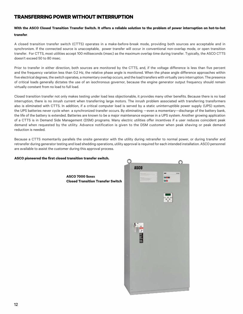
ASCO pioneered the first closed transition transfer switch.
TRANSFERRING POWER WITHOUT INTERRUPTION
With the ASCO Closed Transition Transfer Switch. It offers a reliable solution to the problem of power interruption on hot-to-hot
transfer.
ASCO 7000 SERIES Closed Transition Transfer Switch
12

It enables loads that are too large for the engine-generator to handle as a single block to come on line gradually. The standard closed transition transfer switch applies its load in a block when transferring to the generator set.
The effect of the block loading is even greater with the open transition switch, since motors and transformers have to be reenergized.But, when the size of the load is approximately 80 percent or more of the generator capacity, and the individual loads cannot be divided and connected to smaller, sequenced transfer switches, a soft load power transfer switch can be used.
The soft load switch is similar to a closed transition switch in that it parallels the sources during transfer, but the soft load switch uses an extended parallel time to allow a generating loading control to ramp the load from the utility source to the generator.The difference is a soft load transfer switch takes active control of the engine governor and voltage regulator on the generator and doesn’t just wait for synchronization to occur. Because the sources are paralleled for an extended period of time the ASCO Soft Load Power Transfer Switch contains all the necessary protective functions for extended parallel operation.
ASCO offers two versions of the soft load switch. One uses a conventional UL 1008 listed closed transition transfer switch, the other uses circuit breakers for systems where a service entrance rating or overcurrent protection is necessary.
ASCO also offers a Soft Load Interconnect System (SLIS), which gradually ramps a specific amount of power from the connected bus. This can be used during peak demand periods.
ASCO developed the first closed transition soft load power transfer switch qualified and listed to UL 1008.
EASING LOADS ONTO THE POWER SYSTEM
Is simple with the ASCO 7000 Series Soft Load Power Transfer Switch.
ASCO 7000 SERIES Soft Load Power Transfer Switch
A synchroscope representation on this Control Cen-ter screen shows the relative phase angle between normal and on site power. Among other information shown is phase-to-phase voltage, frequency, kW, kVA and kVAR for each power source.
13
CONTROLLING TRANSFER OPERATIONS
Four elements position ASCO as the leader in control technology:1 . Microprocessor Controller2. Control and Indicator Panel3. Operational parameters4. Power Manager
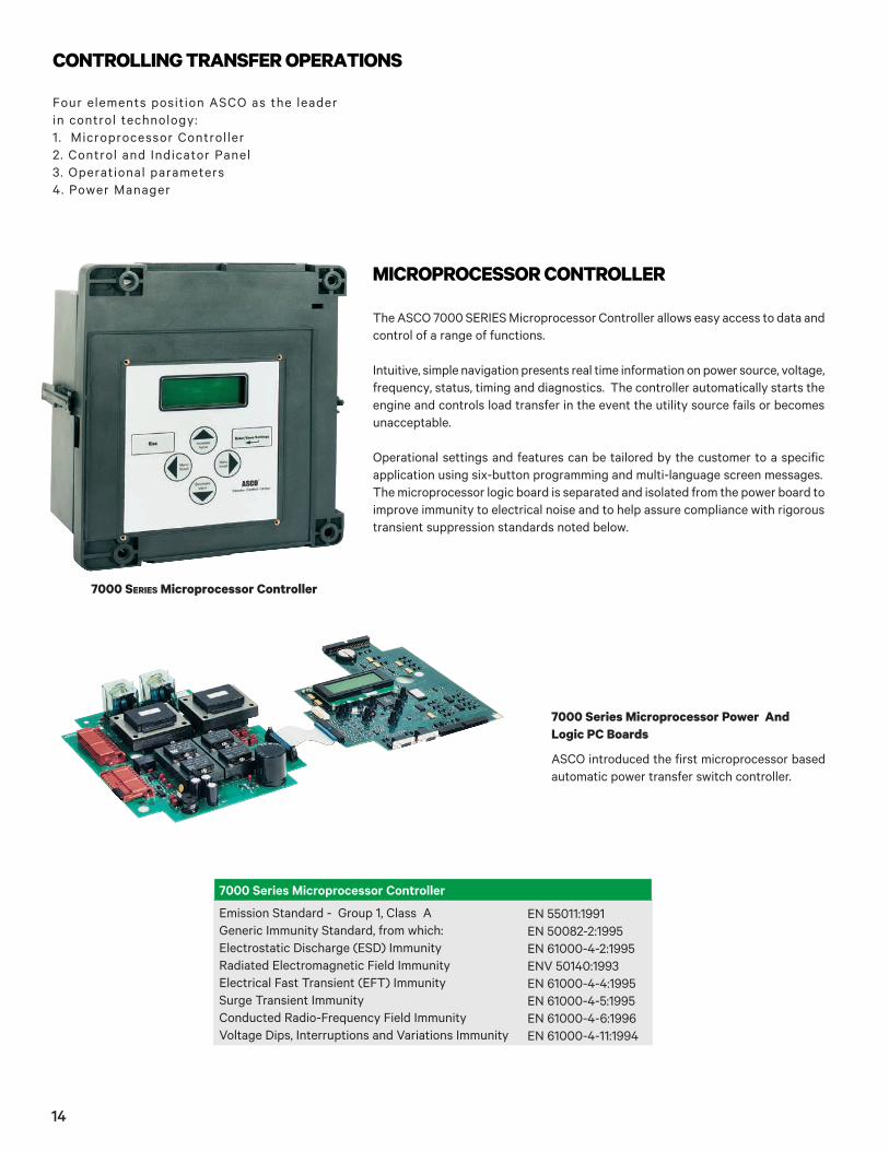
The ASCO 7000 SERIES Microprocessor Controller allows easy access to data and control of a range of functions.
Intuitive, simple navigation presents real time information on power source, voltage, frequency, status, timing and diagnostics. The controller automatically starts the engine and controls load transfer in the event the utility source fails or becomes unacceptable.
Operational settings and features can be tailored by the customer to a specific application using six-button programming and multi-language screen messages. The microprocessor logic board is separated and isolated from the power board to improve immunity to electrical noise and to help assure compliance with rigorous transient suppression standards noted below.
7000 SERIES Microprocessor Controller
7000 Series Microprocessor Power And Logic PC Boards
MICROPROCESSOR CONTROLLER
ASCO introduced the first microprocessor based automatic power transfer switch controller.
7000 Series Microprocessor Controller
Emission Standard - Group 1, Class A Generic Immunity Standard, from which:Electrostatic Discharge (ESD) ImmunityRadiated Electromagnetic Field ImmunityElectrical Fast Transient (EFT) ImmunitySurge Transient ImmunityConducted Radio-Frequency Field ImmunityVoltage Dips, Interruptions and Variations Immunity
EN 55011:1991EN 50082-2:1995EN 61000-4-2:1995ENV 50140:1993EN 61000-4-4:1995EN 61000-4-5:1995EN 61000-4-6:1996EN 61000-4-11:1994
14
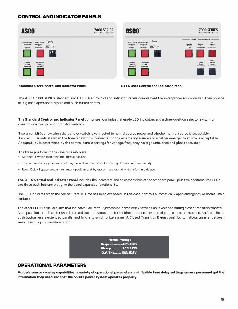
CONTROL AND INDICATOR PANELS
The ASCO 7000 SERIES Standard and CTTS User Control and Indicator Panels complement the microprocessor controller. They provide at-a-glance operational status and push button control.
The Standard Control and Indicator Panel comprises four industrial grade LED indicators and a three-position selector switch for conventional two-position transfer switches.
Two green LEDs show when the transfer switch is connected to normal source power and whether normal source is acceptable.Two red LEDs indicate when the transfer switch is connected to the emergency source and whether emergency source is acceptable.Acceptability is determined by the control panel’s settings for voltage, frequency, voltage unbalance and phase sequence.
The three positions of the selector switch are:• Automatic, which maintains the normal position.
• Test, a momentary position simulating normal source failure for testing the system functionality.
• Reset Delay Bypass, also a momentary position that bypasses transfer and re-transfer time delays.
CTTS User Control and Indicator PanelStandard User Control and Indicator Panel
The CTTS Control and Indicator Panel includes the indicators and selector switch of the standard panel, plus two additional red LEDs and three push buttons that give the panel expanded functionality.
One LED indicates when the pre-set Parallel Time has been exceeded. In this case, controls automatically open emergency or normal main contacts.
The other LED is a visual alarm that indicates Failure to Synchronize if time delay settings are exceeded during closed transition transfer. A red push button—Transfer Switch Locked Out—prevents transfer in either direction, if extended parallel time is exceeded. An Alarm Reset push button resets extended parallel and failure to synchronize alarms. A Closed Transition Bypass push button allows transfer between sources in an open transition mode.
Normal Voltage Dropout.............85%.408V Pickup...............90%.432V O.V. Trip.........110%.528V
OPERATIONAL PARAMETERSMultiple source sensing capabilities, a variety of operational parameters and flexible time delay settings ensure personnel get the information they need and that the on site power system operates properly.
15
Status and Control Parameters
• Output contact for engine-start signals.
• Output signals for remote indication of normal and emergency source acceptability.
• Selection between “commit/no-commit” on transfer to emergency after engine start and normal restores before transfer.
• Advanced inphase transfer algorithm, which automatically measures the frequency difference between the two sources and initiates trans-fer at appropriate phase angle to minimize disturbances when transferring motor loads.
• Event log displays 99 logged events with the time and date of the event, event type and reason.
• Statistical ATS/System monitoring data screens which provide:
— Total number of ATS transfers.
— Number of ATS transfers caused by power source failure.
— Total number of days ATS has operated.
— Total number of hours normal and emergency sources have been available.
Time Delays
• Engine start time delay
• Emergency source stabilization time delay to ignore momentary transients during initial generator set loading.
• Re-transfer to normal time delay with two settings:
— Power failure mode.
— Test mode.
• Unloaded running time delay for engine cool down.
• Pre- and post-transfer signal time delay for selective load disconnect with a programmable bypass on source failures.
• Fully programmable engine exerciser with seven independent routines to exercise the engine-generator, with or without loads, every day, week, two weeks or month.
• Alarm signals, logic and time delays for use with closed transition switches.
— Insynch time.
— Failure to synchronize.
— Extended parallel.
• Delayed transition load disconnect time delay.
ASCO 5200 SERIES POWER METERINGThe ASCO 5200 SERIES Power Meters are microprocessor based metering devices that provides real-time measurement of single and three phase power systems. The 5200 SERIES uses digital signal processing technology to measure voltage and current per phase; real, reactive and apparent power, and bidirectional energy. All measurements can be viewed locally with a backlit liquid crystal display and/or displayed remotely with ASCO PowerQuest® products.
Voltage and Frequency Sensing
• True RMS Voltage Sensing with +/- 1% accuracy; Frequency Sensing Accuracy is +/- 0.2%.
• Adjustable under and over voltage sensing on normal and emergency sources.
• Adjustable under and over frequency sensing on normal and emergency.
• Selectable settings: single or three phase voltage.
• Sensing on normal and emergency; 50 or 60Hz.
• Phase sequence monitoring for phase sensitive loads.
• Voltage unbalance monitoring between phases.
16

Power Metering
• Voltage: Line - Line: VAB, VBC, VCA, VAVERAGE Line - Neutral: VAN, VBN, VCN, VAVERAGE
• Frequency: 45.0 to 66.0 Hertz
• Current: IA, IB, IC, IAVERAGE
• Unbalance %: Voltage, Amps
• Real Power: KWA, KWB, KWC, KWNET
• Reactive Power: KVARA, KVARB, KVARC, KVARNET
• Apparent Power: KVAA, KVAB, KVAC, KVANET
• Real Energy: KWHIMPORT, KWHEXPORT, KWHNET
• Reactive Energy: KVARHIMPORT, KVARHEXPORT, KVARHNET
• Power Factor: PFA, PFB, PFC, PFNET
Configurable Designations
• Local - A four line, 20 character LCD backlit display.
• 5220 Power Manager provides user programmable setpoints based on twelve metering and I/O parameters. Each set point allows the user to select the parameter, the trip & reset levels, the trip & reset time delays and the alarm type or relay output to trigger. This can be used for protective relaying and peak shaving applications.
• 100 event data logging feature.
Integrated ATS Features
When configured on load of ATS:
• Displays ATS position.
• Displays power data as a function of ATS position (normal/emergency).
• Accumulates energy data separately for normal and emergency sources.
ASCO 5210 Power Meter
Direct voltage input for systems up to 600 Volts AC can be monitored without the use of external potential transformers (PTs). Measures three phase currents and a fourth current input is available for measuring current in the neutral conductor. The 5200 SERIES includes one discrete input for transfer switch position.
Optional Configurations and Connection ArrangementsConnected To: 5210 Load Acc. 85L
Normal Acc. 85N
Emergency Acc. 85M
Load (BPS only) N/A Add suffix “A1” to above metering designations if neutral conductor monitoring is required.
Note: Accessory 85 and 135 includes component mounting, CTs, shorting blocks and all necessary inter wiring.
*Bypass & isolation switch contacts wired to discrete Power Manager inputs.
17
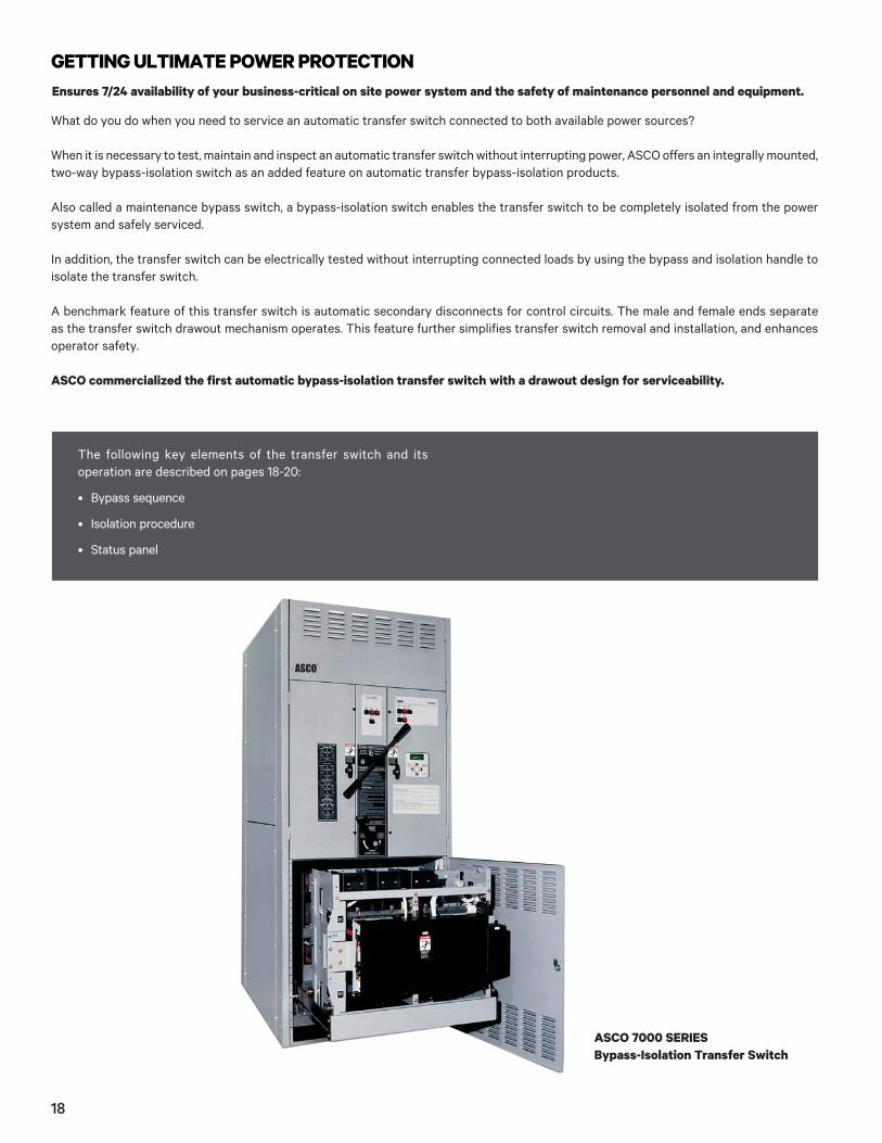
GETTING ULTIMATE POWER PROTECTIONEnsures 7/24 availability of your business-critical on site power system and the safety of maintenance personnel and equipment.
What do you do when you need to service an automatic transfer switch connected to both available power sources?
When it is necessary to test, maintain and inspect an automatic transfer switch without interrupting power, ASCO offers an integrally mounted, two-way bypass-isolation switch as an added feature on automatic transfer bypass-isolation products.
Also called a maintenance bypass switch, a bypass-isolation switch enables the transfer switch to be completely isolated from the power system and safely serviced.
In addition, the transfer switch can be electrically tested without interrupting connected loads by using the bypass and isolation handle to isolate the transfer switch.
A benchmark feature of this transfer switch is automatic secondary disconnects for control circuits. The male and female ends separate as the transfer switch drawout mechanism operates. This feature further simplifies transfer switch removal and installation, and enhances operator safety.
ASCO commercialized the first automatic bypass-isolation transfer switch with a drawout design for serviceability.
ASCO 7000 SERIES Bypass-Isolation Transfer Switch
The following key elements of the transfer switch and its operation are described on pages 18-20:
• Bypass sequence
• Isolation procedure
• Status panel
18
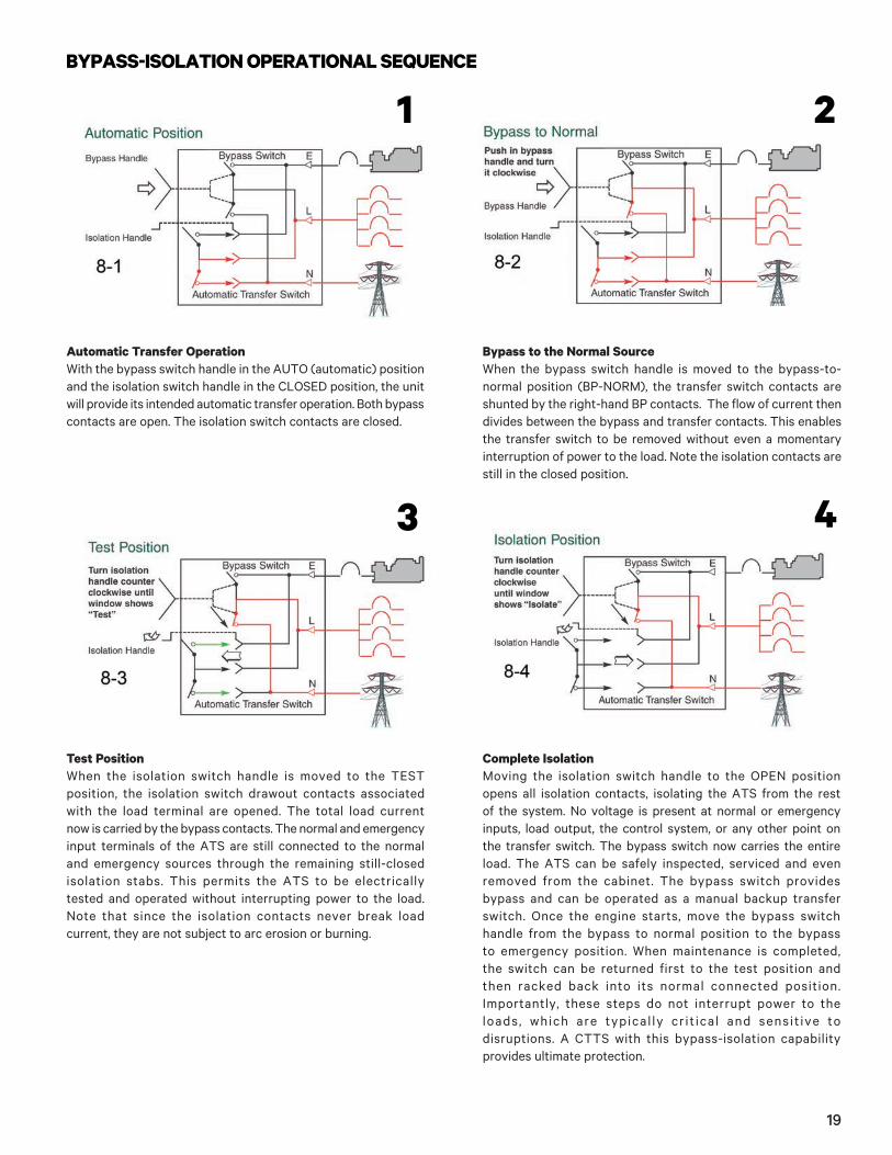
Complete IsolationMoving the isolation switch handle to the OPEN positionopens all isolation contacts, isolating the ATS from the restof the system. No voltage is present at normal or emergency inputs, load output, the control system, or any other point onthe transfer switch. The bypass switch now carries the entireload. The ATS can be safely inspected, serviced and evenremoved from the cabinet. The bypass switch providesbypass and can be operated as a manual backup transferswitch. Once the engine starts, move the bypass switchhandle from the bypass to normal position to the bypassto emergency position. When maintenance is completed,the switch can be returned first to the test position andthen racked back into its normal connected position.Importantly, these steps do not interrupt power to theloads, which are typical ly cr it ical and sensit ive todisruptions. A CTTS with this bypass-isolation capabilityprovides ultimate protection.
Bypass to the Normal SourceWhen the bypass switch handle is moved to the bypass-to-normal position (BP-NORM), the transfer switch contacts are shunted by the right-hand BP contacts. The flow of current then divides between the bypass and transfer contacts. This enables the transfer switch to be removed without even a momentary interruption of power to the load. Note the isolation contacts are still in the closed position.
Automatic Transfer Operation With the bypass switch handle in the AUTO (automatic) position and the isolation switch handle in the CLOSED position, the unit will provide its intended automatic transfer operation. Both bypass contacts are open. The isolation switch contacts are closed.
Test PositionWhen the isolation switch handle is moved to the TEST position, the isolation switch drawout contacts associated with the load terminal are opened. The total load current now is carried by the bypass contacts. The normal and emergency input terminals of the ATS are still connected to the normal and emergency sources through the remaining still-closed isolation stabs. This permits the ATS to be electrically tested and operated without interrupting power to the load. Note that since the isolation contacts never break load current, they are not subject to arc erosion or burning.
BYPASS-ISOLATION OPERATIONAL SEQUENCE
1 2
3 4
19
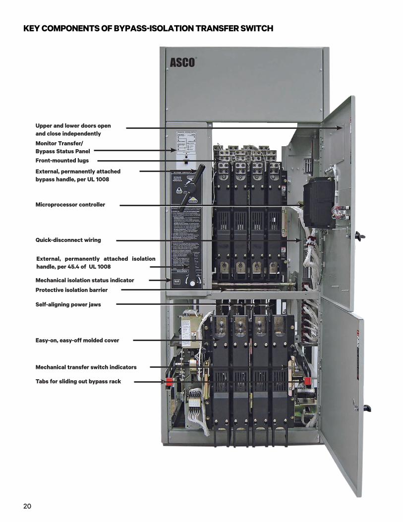
KEY COMPONENTS OF BYPASS-ISOLATION TRANSFER SWITCH
Monitor Transfer/ Bypass Status Panel
Mechanical isolation status indicator
External, permanently attached bypass handle, per UL 1008
Microprocessor controller
External, permanently attached isolation handle, per 45.4 of UL 1008
Front-mounted lugs
Protective isolation barrier
Mechanical transfer switch indicators
Easy-on, easy-off molded cover
Upper and lower doors open and close independently
Quick-disconnect wiring
Self-aligning power jaws
Tabs for sliding out bypass rack
20
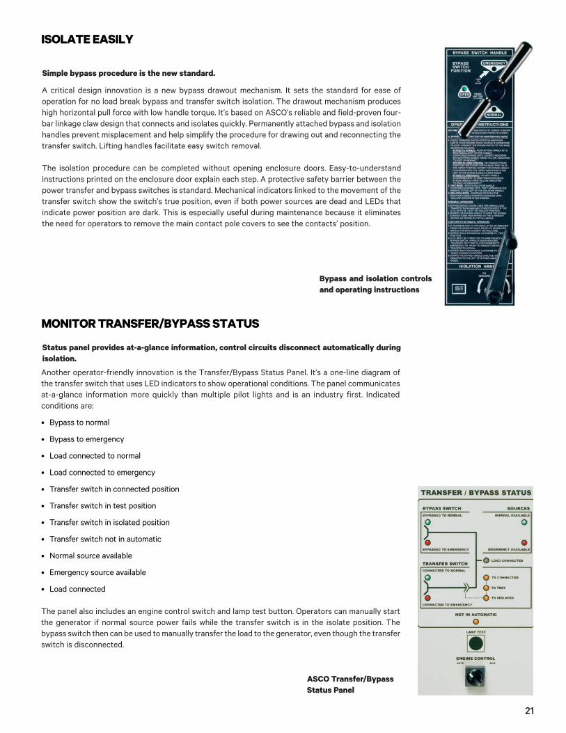
ASCO Transfer/Bypass Status Panel
Another operator-friendly innovation is the Transfer/Bypass Status Panel. It’s a one-line diagram of the transfer switch that uses LED indicators to show operational conditions. The panel communicates at-a-glance information more quickly than multiple pilot lights and is an industry first. Indicated conditions are:
• Bypass to normal
• Bypass to emergency
• Load connected to normal
• Load connected to emergency
• Transfer switch in connected position
• Transfer switch in test position
• Transfer switch in isolated position
• Transfer switch not in automatic
• Normal source available
• Emergency source available
• Load connected
The panel also includes an engine control switch and lamp test button. Operators can manually start the generator if normal source power fails while the transfer switch is in the isolate position. The bypass switch then can be used to manually transfer the load to the generator, even though the transfer switch is disconnected.
MONITOR TRANSFER/BYPASS STATUS
Status panel provides at-a-glance information, control circuits disconnect automatically during isolation.
Bypass and isolation controls and operating instructions
A critical design innovation is a new bypass drawout mechanism. It sets the standard for ease of operation for no load break bypass and transfer switch isolation. The drawout mechanism produces high horizontal pull force with low handle torque. It’s based on ASCO’s reliable and field-proven four-bar linkage claw design that connects and isolates quickly. Permanently attached bypass and isolation handles prevent misplacement and help simplify the procedure for drawing out and reconnecting the transfer switch. Lifting handles facilitate easy switch removal.
The isolation procedure can be completed without opening enclosure doors. Easy-to-understand instructions printed on the enclosure door explain each step. A protective safety barrier between the power transfer and bypass switches is standard. Mechanical indicators linked to the movement of the transfer switch show the switch’s true position, even if both power sources are dead and LEDs that indicate power position are dark. This is especially useful during maintenance because it eliminates the need for operators to remove the main contact pole covers to see the contacts’ position.
ISOLATE EASILY
Simple bypass procedure is the new standard.
21

The power transfer switch meets all UL and National Electrical Code requirements for a service rated transfer switch or transfer switch/bypass isolation switch.
Service entrance rated transfer switches generally are installed at facilities that have a single utility feed and a single emergency power source. A circuit breaker serves as the service disconnect and links are provided to disconnect both neutral and ground connections.
The product is designed and manufactured in accordance with UL 891 Switchboard requirements. The transfer switch is UL 1008 listed and is available up to 600V and 4000A in standard, delayed, closed transition, soft load, and bypass-isolation configurations.
The ASCO 7000 SERIES Service Entrance Rated Transfer Switch combines automatic power switching with an overcurrent service disconnect device on the utility source.
With a Service Entrance Rated Transfer Switch.
ASCO 7000 SERIES Service Entrance Rated Transfer Switch
MANAGING UTILITY FEEDS AND EMERGENCY POWER
One line diagram of a typical service entrance rated transfer switch. It’s available with solid, switched or overlapping neutral poles.
2
1 GFCT - Ground Fault Current Transformer2 ATS - Automatic Transfer Switch
1
ASCO debuted the first true service entrance transfer switch that integrates the switch and service disconnect.
22
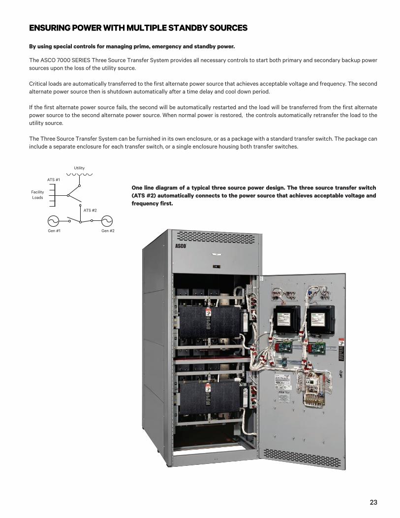
By using special controls for managing prime, emergency and standby power.
The ASCO 7000 SERIES Three Source Transfer System provides all necessary controls to start both primary and secondary backup power sources upon the loss of the utility source.
Critical loads are automatically transferred to the first alternate power source that achieves acceptable voltage and frequency. The second alternate power source then is shutdown automatically after a time delay and cool down period.
If the first alternate power source fails, the second will be automatically restarted and the load will be transferred from the first alternate power source to the second alternate power source. When normal power is restored, the controls automatically retransfer the load to the utility source.
The Three Source Transfer System can be furnished in its own enclosure, or as a package with a standard transfer switch. The package can include a separate enclosure for each transfer switch, or a single enclosure housing both transfer switches.
ENSURING POWER WITH MULTIPLE STANDBY SOURCES
One line diagram of a typical three source power design. The three source transfer switch (ATS #2) automatically connects to the power source that achieves acceptable voltage and frequency first.
Utility
ATS #2
Gen #1 Gen #2
ATS #1
FacilityLoads
23
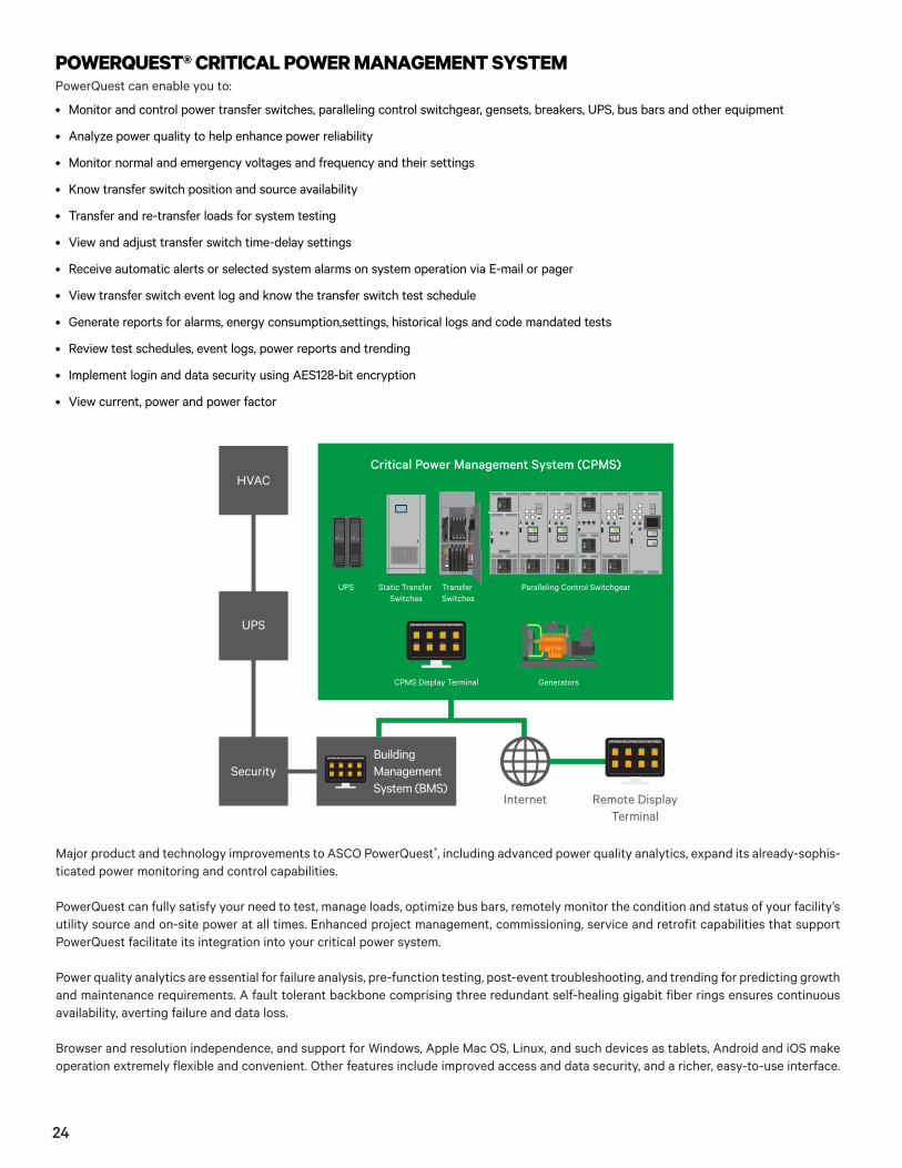
Major product and technology improvements to ASCO PowerQuest®, including advanced power quality analytics, expand its already-sophis-ticated power monitoring and control capabilities.
PowerQuest can fully satisfy your need to test, manage loads, optimize bus bars, remotely monitor the condition and status of your facility’s utility source and on-site power at all times. Enhanced project management, commissioning, service and retrofit capabilities that support PowerQuest facilitate its integration into your critical power system.
Power quality analytics are essential for failure analysis, pre-function testing, post-event troubleshooting, and trending for predicting growth and maintenance requirements. A fault tolerant backbone comprising three redundant self-healing gigabit fiber rings ensures continuous availability, averting failure and data loss.
Browser and resolution independence, and support for Windows, Apple Mac OS, Linux, and such devices as tablets, Android and iOS make operation extremely flexible and convenient. Other features include improved access and data security, and a richer, easy-to-use interface.
PowerQuest can enable you to:
• Monitor and control power transfer switches, paralleling control switchgear, gensets, breakers, UPS, bus bars and other equipment
• Analyze power quality to help enhance power reliability
• Monitor normal and emergency voltages and frequency and their settings
• Know transfer switch position and source availability
• Transfer and re-transfer loads for system testing
• View and adjust transfer switch time-delay settings
• Receive automatic alerts or selected system alarms on system operation via E-mail or pager
• View transfer switch event log and know the transfer switch test schedule
• Generate reports for alarms, energy consumption,settings, historical logs and code mandated tests
• Review test schedules, event logs, power reports and trending
• Implement login and data security using AES128-bit encryption
• View current, power and power factor
POWERQUEST® CRITICAL POWER MANAGEMENT SYSTEM
Static Transfer Switches
Transfer Switches
Paralleling Control Switchgear
GeneratorsCPMS Display Terminal
HVACCritical Power Management System (CPMS)
UPS
Security
Internet Remote DisplayTerminal
BuildingManagementSystem (BMS)
UPS
24
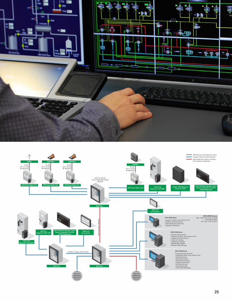
7000 ATBRequired: ACC.150bt
300 ATSRequired: 72EE+1UP
5350 ATS Annunciator
ASCO Remote Operator Touch Panel or Desktop PC (5700
CPMS Requiered)
Utility
5160 RCU
7000 ATBRequired: ACC.150bt
ASCO Remote Operator Touch Panel or Desktop PC (5700
CPMS Requiered)
5350 ATS Annunciator
5211 Power Meter Unit
5211 Power Meter Unit
5160 RCU
5160 RCU
Liebert UPS (Requires Unity-DP Card)
Generator
Breaker
5211 Power Meter Unit
Generator
5211 Power Meter Unit
To RCU and
Additional Networked
Devices
To RCU and
Additional Networked
Devices
24 VDCQTY 4, 14 Awg3P Volts/Amps
24 VDCQTY 4, 14 Awg3P Volts/Amps
24 VDCQTY 4, 14 Awg3P Volts/Amps
24VDC or 120 VAC25 sec. Power Ride-Through
NEMA 3R
Category 6 Copper, 300 Feet Max
24 VDCQTY 4, 14 Awg3P Volts/Amps
• Supports 3 ASCO Touch Panels or PCs• Supports 32 Power Devices• Basic Monitoring and Control• Standard Performance
5710 CPMS Server
Essential Features PLUS:• Supports 10 ASCO Touch Panels or PCs• Supports 64 Power Devices• Historical Trending• 5 Reporting Packages• BMS Modbus Support• Remote E-Mail Alarming
5750 CPMS Server
Professional Features PLUS:• Supports25 ASCO Touch Panels or PCs• Redundant Power• Redundant Storage• Redundant Processors• Ultimate Performance• 128 Power Devices• Expanded Storage• Inter-facility Messaging
5790 CPMS Server
5700 CPMS ServersNote - Select One Server to install
50˚ to 95˚F (10 C̊ to 35 C̊)
AWG Wire Size and Distance by othersCategory 6 Ethernet (300 Feet Max)
Multi-Mode Fiber, 1300nm, 50/125um, ST Connectors (1-Mile Max)
25

Because power failures can be life-threatening and costly, there is no room for procrastination when it comes to testing and maintaining power transfer switches and paralleling control switchgear. Skilled, ASCO trained Services technicians properly maintain and testtransfer switches and power control systems coast to coast. Technicians check operation of engine-generator paralleling systems and transfer switches with a laptop computer. The computer tests multiple components quickly and accurately and can send maintenance results to a printer for hard-copy documentation. Technicians are available 24/7 in most areas. Fully stocked vans support the technicians during on site visits, often eliminating the need to order parts. ASCO Services maintains and upgrades a range of transfer switches from a variety of manufacturers. Technicians resolve problems created by corrosion, evidence of overheating, contact erosion and a number of other causes. Besides maintaining equipment, ASCO Services can install and upgrade power transfer switches and power control systems.
ASCO Services is the largest organization of its kind in the United States.
RELYING ON 24/7 SERVICE Avert the most common cause of transfer switch failure: lack of regular maintenance.
Two levels of maintenance programs can be customized to meet the needs of one facility or many networked facilities. The Essential program provides your power switching and controls with the necessary care they need to ensure proper operation.
The Preferred program provides your equipment with every aspect of care. The Preferred program can greatly reduce the potential for unexpected problems and unexpected costs. This allows your facility to budget for the service of your equipment in advance. For more information on ASCO Services preventative maintenance care see publications 3241.
Maintenance Programs
Demands considerable record-keeping that too often can mean personnel spend many hours operating on site power systems and recording data manually.
MEETING OR EXCEEDING CODE REQUIREMENTS
Weekly inspection sheets for an emergency power system can include 55 or more data points and require writing comments in long hand. Monthly testing logs can have nearly 40 or more data points. A third form, a generator load report, builds the pile of necessary paperwork. It’s no wonder that errors can and do occur.
A solution to testing emergency power systems more e�iciently is to automate the testing procedure and data recording. Automatingthe process facilitates compliance, substantiates insurance claims and defends against litigation arising from potentially life-threatening events. It also helps manage the facility’s energy consumption more e�ectively. An automated Web-based communications system –POWERQUEST®– integrates the operation of monitoring and controlling, multiple engine-generator paralleling systems and automatic power transfer switches. The 7000 SERIES Controller automatically exercises engine-generator systems and logs data during the process.
26

* Joint Commission on Accreditation of Healthcare Organizations
ASCO TECHNOLOGY MEETS OR EXCEEDS NEW SEISMIC REQUIREMENTSASCO Automatic Transfer Switches and Power Control Systems meet or exceed the IBC 2012 standard ground acceleration requirement of 2.50 Sds, including the CBC and Section 13.1.3 of ASCE 7-05 seismic standards.
Regardless of the Occupancy Category, Seismic Design Category or Importance Fa tor specified for your project, ASCO o�ers qualified and thoroughly certified products to meet these requirements. A Certificate of Compliance, seismic nameplate and special drawings are furnished with the product. Also standard is ASCO participation in your Quality Assurance program for facilitating code compliance, proper installation and commissioning.
The products all have been physically tested on tri-axial seismic simulators. Mounting bolts remain seated, doors remain shut and, the robust design of mechanically locked critical components, such as the main contacts remain in their intended position during testing.
ASCO products operated during and after testing. So even during an actual seismic event, they’re ready to sense loss of normal source, signal gensets to start and transfer power reliably. ASCO technology eliminates the question of whether the power switching and controls equipment is properly certified, even for demanding rooftop installations. Minimize your exposure to risk, liability, the potential for red-tagged equipment and insurance issues. Compare, then specify ASCO. Bottom line, it’s peace of mind. Yours.
POWERQUEST® can conduct transfer tests remotely that simulate a power failure, start the gen-set, transfer the load to the alternate power source and run the generator under load for the period specified in the codes and standards. POWERQUEST® then initiates retransfers back to normal power and runs the generator through cool down. The system monitors the engine-generators throughout the test and automatically records readings. Personnel can select from seven automatic test schedules. Code references for NFPA 99 emergency power systems testing are included in POWERQUEST®. The transfer switch controller stores up to 99 events with time and date stamping. An optional printer interface produces hard-copy documentation. An ASCO Power Manager module measures single and three phase power systems in real time. The bottom line is an integrated emergency power system that better equips maintenance and engineering sta�s to meet the requirements of NFPA 110, NFPA 99 and, for healthcare organizations, the JCAHO*.
27
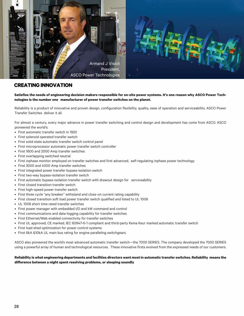
Satisfies the needs of engineering decision makers responsible for on-site power systems. It’s one reason why ASCO Power Tech-nologies is the number one manufacturer of power transfer switches on the planet.
Reliability is a product of innovative and proven design, configuration flexibility, quality, ease of operation and serviceability. ASCO Power Transfer Switches deliver it all.
For almost a century, every major advance in power transfer switching and control design and development has come from ASCO. ASCO pioneered the world’s:• First automatic transfer switch in 1920• First solenoid operated transfer switch• First solid state automatic transfer switch control panel• First microprocessor automatic power transfer switch controller• First 1600 and 2000 Amp transfer switches• First overlapping switched neutral• First inphase monitor employed on transfer switches and first advanced, self-regulating inphase power technology• First 3000 and 4000 Amp transfer switches• First integrated power transfer bypass-isolation switch• First two-way bypass-isolation transfer switch• First automatic bypass-isolation transfer switch with drawout design for serviceability• First closed transition transfer switch• First high-speed power transfer switch• First three cycle “any breaker” withstand and close-on current rating capability• First closed transition soft load power transfer switch qualified and listed to UL 1008• UL 1008 short time rated transfer switches• First power manager with embedded I/O and kW command and control• First communications and data-logging capability for transfer switches• First Ethernet/Web enabled connectivity for transfer switches• First UL approved, CE marked, IEC 60947-6-1 compliant and third-party Kema Keur marked automatic transfer switch• First load shed optimization for power control systems • First 6kA &10kA UL main bus rating for engine paralleling switchgears.
ASCO also pioneered the world’s most advanced automatic transfer switch—the 7000 SERIES. The company developed the 7000 SERIES using a powerful array of human and technological resources. These innovative firsts evolved from the expressed needs of our customers.
Reliability is what engineering departments and facilities directors want most in automatic transfer switches. Reliability means the di�erence between a night spent resolving problems, or sleeping soundly
CREATING INNOVATION
Armand J VisioliPresident,
ASCO Power Technologies
28

Technological tools such as 3-D computer-aided modeling facilitate the design process. Finite element analysis helps engineering teams design components that manage magnetic and mechanical stresses dependably.
Teams evaluate prototypes with fused deposition modeling and a state-of-the-art power lab. The lab verifies performance under real condi-tions and qualifies designs to listing agency standards. High-speed video photography enables engineers to analyze how designs react to stress over time frames of a few milliseconds.
The result is a continuing stream of innovations in power transfer technology that meets the evolving needs of hospitals, data and financial centers, and other business-critical facilities.
Besides innovative technology, ASCO o�ers the security of a dependable company large enough to satisfy customers’ evolving need for ap-plication support, project management and 24/7 field service. Whatever the challenge, ASCO can help facility engineers keep their power on.
Experienced engineers with decades of accomplishments and advanced degrees employ cutting-edge design to test and qualify innovative transfer switch technology.
The world’s most sophisticated power transfer technology comes to life as the 7000 SERIES Automatic Transfer Switch family. In terms of configuration flexibility, the family is based on a four-pole architecture and a single or dual solenoid operator. Also, one controller is utilized for all amperages, voltages, frequencies and transfer switch configurations (open transition, delayed transition, closed transition and soft load).
Quality is assured with the ISO 9001:2000 certification earned by ASCO for its production facilities. ASCO Power Transfer Switches are easy to operate because information-rich, menu-driven and multi-language displays are intuitive for virtually any operator.
A CASE IN POINT
THROUGH HIGH TECHNOLOGY
29

www.ascopower.com www.ascoapu.com
ASCO. Innovative Solutions.
ASCO Power Technologies - Global Headquarters160 Park Avenue
Florham Park, NJ 07932Tel: 800 800 ASCO
The ASCO and ASCO Power Technologies marks are owned by Emerson Electric Co. or its a�iliates and utilized herein under license. ©2017 ASCO Power Technologies. All Rights Reserved.Publication 3158 R7 © February, 2017 Printed in the U.S.A.