as featured in - fudan university
TRANSCRIPT
Registered charity number: 207890
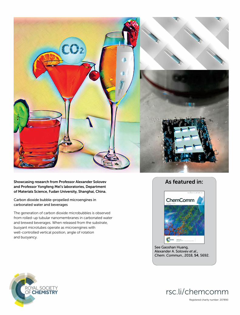
Showcasing research from Professor Alexander Solovev
and Professor Yongfeng Mei’s laboratories, Department
of Materials Science, Fudan University, Shanghai, China.
Carbon dioxide bubble-propelled microengines in
carbonated water and beverages
The generation of carbon dioxide microbubbles is observed
from rolled-up tubular nanomembranes in carbonated water
and brewed beverages. When released from the substrate,
buoyant microtubes operate as microengines with
well-controlled vertical position, angle of rotation
and buoyancy.
rsc.li/chemcomm
As featured in:
See Gaoshan Huang, Alexander A. Solovev et al., Chem. Commun., 2018, 54, 5692.

5692 | Chem. Commun., 2018, 54, 5692--5695 This journal is©The Royal Society of Chemistry 2018
Cite this:Chem. Commun., 2018,
54, 5692
Carbon dioxide bubble-propelled microenginesin carbonated water and beverages†
Yan Zhang, Hong Zhu, Wenxuan Qiu, Yilu Zhou, Gaoshan Huang, *Yongfeng Mei and Alexander A. Solovev *
We demonstrate a new type of gaseous fuel for rolled-up tubular
Ti/Cr microengine powered by carbon dioxide microbubbles in
carbonated water and brewed beverages. Existence of microbubble
pockets is revealed using on-chip integrated transparent micro-
tubes. Vertical position, angle of rotation and buoyancy of ferro-
magnetic Ti/Fe/Cr microengines are controlled using an external
magnetic field.
Autonomous nano-/micro-motors and engines1–6 show multiplepotential applications including drug delivery,7,8 biosensing inmotion9 and environmental remediation.10 Bubble-propelled tubularmicroengines have several advantages including high speed,motive power and efficiency.3,11–13 It is a common belief that therealization of alternative fuels is the next important prerequisitefor further advancement in biomedical applications of nano/micromotors.14 Emerging materials for fabrication and applicationsof micromotors have recently been considered by the groups ofEscarpa15 and Pumera.16,17 Fuel-free motion, such as ultrasound18
and magnetic field19 driven micro-/nanomotors, are demonstrated.Alternatively, enzymes such as catalase, urease, or glucose oxidase(upon addition of corresponding substrates: H2O2, urea andglucose),20 and reactions between magnesium–water21 and alumi-num alloy–water22 have been identified as promising approaches topower micromotors. However, a number of important limitationsshould be taken into account. For instance, for an operation ofmicroengines in vivo, both fuels and reaction products must be apart of the metabolic pathways or cellular respiration. Carbondioxide (CO2) is a well-known organic compound required forphotosynthesis and in beverage industries and thus is one of themost feasible gaseous fuels for micromachines. Recently, Schmidt’sgroup demonstrated motion of calcium carbonate Janus particles inultra-light acidic environment generated by cancer cells accordingto the reaction: CaCO3 + 2H+ - Ca2+ + CO2 + H2O.23 Still, carbonate
micromotors have a limited lifetime, resulting in dissolution withina couple of minutes. In another study, Wang’s group demonstratedrapid CO2 sequestration by hydrogen peroxide-driven micro-motors.24 Pumera and co-workers achieved acetylene bubble-powered capsules driven by the reaction of calcium carbide withwater as a co-reactant.25 Nucleation and generation of bubbles bringforth fundamental interests in research, and the utilization of theunique bubble properties at the micro- and nano-scale such asstability, lifetime, contraction, dissolution, growth, coalescence,cavitation, surface charge, surface area, flexibility/rigidity of air-gasinterface, internal pressure, buoyancy, growth and mass transferrates.26 Micro- and nanobubbles are used for ultrasound biomedicalimaging, cleaning of rivers and lakes, water purification, frothflotation, additives to fuels and oil reservoirs, etc. In contrast tohomogeneous nucleation in liquid, heterogeneous bubble nuclea-tion on solid surfaces reduces the energy barrier required for bubblenucleation. In addition, stored bubble pockets or stable gas embryoscan lower the energy barrier required for stable generation ofbubbles. For instance, pouring of carbonated water and brewedbeverages leads to stable nucleation, expansion, growth and gen-eration of bubbles from the pre-existing gas pockets entrapped inthe surface defects, crevices, pits or cavities.27 The subsequentgrowth and generation of bubbles depends strongly on the size ofsurface imperfections, wetting properties of the surface, diffusion ofmolecules and gas saturation in a liquid. According to Jones, Evansand Galvin, if pre-existing gas cavities can house menisci with radiiof curvature greater than the critical nucleation value, they provide astable source for bubble nucleation.28 Several examples of bubblenucleation are reported in small capillary tubes29 and cellulosefibers,30 resembling Taylor-like bubbles trapped in microchannels.In cellulose fiber, the gas pocket remains entrapped inside themicrotube, where it grows and generates bubbles at stable rates.31,32
Usually, the size of bubbles can be controlled by external pressure,33
CO2 dissolution rate,34 liquid temperature35 and hydrophobicity ofthe surface.36
Herein, we report a new type of CO2 fuel for bubble-propelledmicroengines consisting of rolled-up Ti/Cr, Ti/Fe/Cr and SiO/SiO2
nanomembranes. Our previous method of strain-engineered
Department of Materials Science, Fudan University, 220 Handan Rd, Shanghai,
P. R. China. E-mail: [email protected], [email protected]
† Electronic supplementary information (ESI) available. See DOI: 10.1039/c8cc01011k
Received 5th February 2018,Accepted 27th March 2018
DOI: 10.1039/c8cc01011k
rsc.li/chemcomm
ChemComm
COMMUNICATION
Publ
ishe
d on
29
Mar
ch 2
018.
Dow
nloa
ded
by F
udan
Uni
vers
ity o
n 9/
4/20
18 2
:02:
43 A
M.
View Article OnlineView Journal | View Issue
This journal is©The Royal Society of Chemistry 2018 Chem. Commun., 2018, 54, 5692--5695 | 5693
nanomembranes on polymers was used to fabricate microtubeswith well-controlled wall thickness, diameter, length and a numberof rotations.4 Herein, we tested several samples (S1: Ti/Cr tubes onphotoresist; S2: Ti/Cr, Ti/Fe/Cr on table salt; S3: SiO/SiO2 onphotoresist) using a fabrication procedure described elsewhere.4
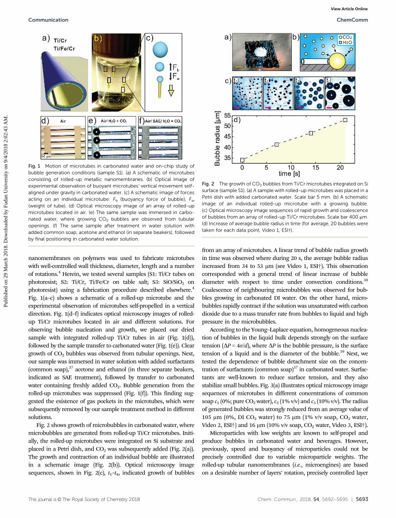
Fig. 1(a–c) shows a schematic of a rolled-up microtube and theexperimental observation of microtubes self-propelled in a verticaldirection. Fig. 1(d–f) indicates optical microscopy images of rolled-up Ti/Cr microtubes located in air and different solutions. Forobserving bubble nucleation and growth, we placed our driedsample with integrated rolled-up Ti/Cr tubes in air (Fig. 1(d)),followed by the sample transfer to carbonated water (Fig. 1(e)). Cleargrowth of CO2 bubbles was observed from tubular openings. Next,our sample was immersed in water solution with added surfactants(common soap),37 acetone and ethanol (in three separate beakers,indicated as SAE treatment), followed by transfer to carbonatedwater containing freshly added CO2. Bubble generation from therolled-up microtubes was suppressed (Fig. 1(f)). This finding sug-gested the existence of gas pockets in the microtubes, which weresubsequently removed by our sample treatment method in differentsolutions.
Fig. 2 shows growth of microbubbles in carbonated water, wheremicrobubbles are generated from rolled-up Ti/Cr microtubes. Initi-ally, the rolled-up microtubes were integrated on Si substrate andplaced in a Petri dish, and CO2 was subsequently added (Fig. 2(a)).The growth and contraction of an individual bubble are illustratedin a schematic image (Fig. 2(b)). Optical microscopy imagesequences, shown in Fig. 2(c), t1–t4, indicated growth of bubbles
from an array of microtubes. A linear trend of bubble radius growthin time was observed where during 20 s, the average bubble radiusincreased from 34 to 53 mm (see Video 1, ESI†). This observationcorresponded with a general trend of linear increase of bubblediameter with respect to time under convection conditions.38
Coalescence of neighbouring microbubbles was observed for bub-bles growing in carbonated DI water. On the other hand, micro-bubbles rapidly contract if the solution was unsaturated with carbondioxide due to a mass transfer rate from bubbles to liquid and highpressure in the microbubbles.
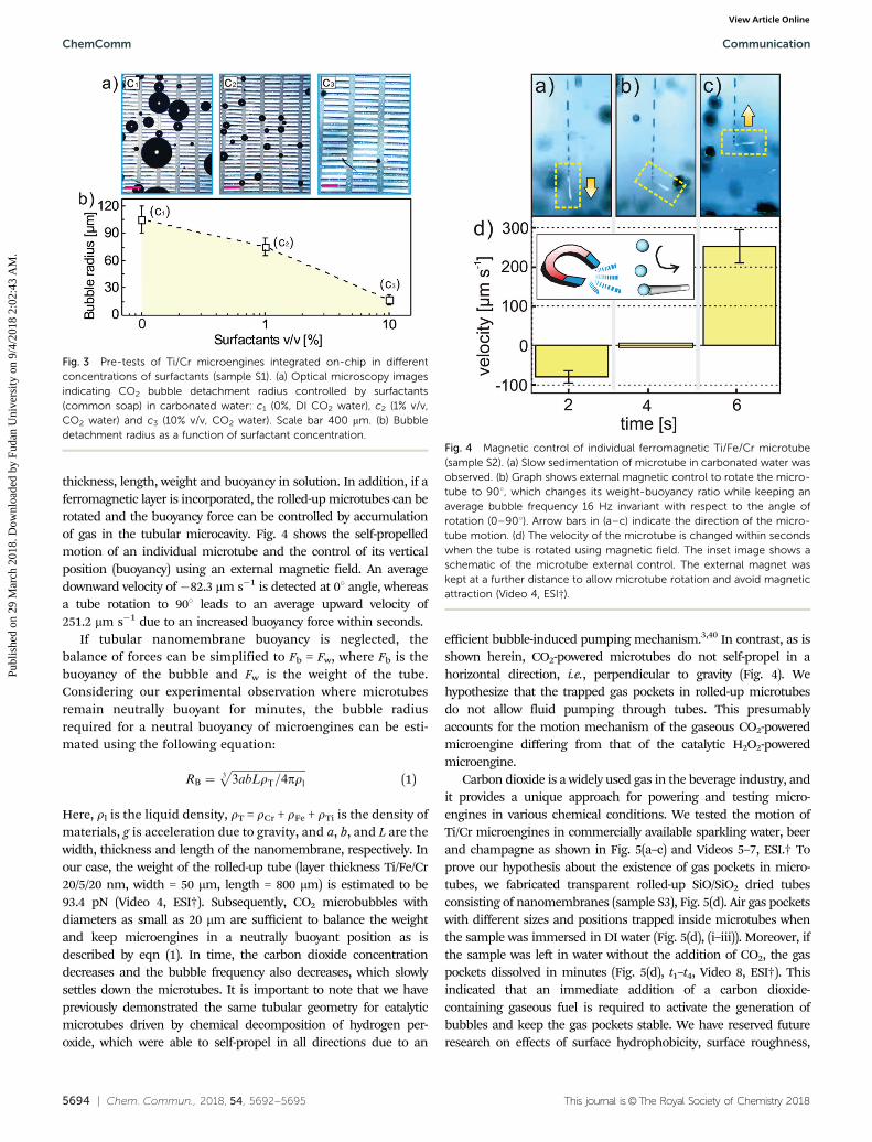
According to the Young–Laplace equation, homogeneous nuclea-tion of bubbles in the liquid bulk depends strongly on the surfacetension (DP = 4s/d), where DP is the bubble pressure, is the surfacetension of a liquid and is the diameter of the bubble.39 Next, wetested the dependence of bubble detachment size on the concen-tration of surfactants (common soap)37 in carbonated water. Surfac-tants are well-known to reduce surface tension, and they alsostabilize small bubbles. Fig. 3(a) illustrates optical microscopy imagesequences of microtubes in different concentrations of commonsoap c1 (0%; pure CO2 water), c2 (1% v/v) and c3 (10% v/v). The radiusof generated bubbles was strongly reduced from an average value of105 mm (0%, DI CO2 water) to 75 mm (1% v/v soap, CO2 water,Video 2, ESI†) and 16 mm (10% v/v soap, CO2 water, Video 3, ESI†).
Microparticles with low weights are known to self-propel andproduce bubbles in carbonated water and beverages. However,previously, speed and buoyancy of microparticles could not beprecisely controlled due to variable microparticle weights. Therolled-up tubular nanomembranes (i.e., microengines) are basedon a desirable number of layers’ rotation, precisely controlled layer
Fig. 1 Motion of microtubes in carbonated water and on-chip study ofbubble generation conditions (sample S1). (a) A schematic of microtubesconsisting of rolled-up metallic nanomembranes. (b) Optical image ofexperimental observation of buoyant microtubes’ vertical movement self-aligned under gravity in carbonated water. (c) A schematic image of forcesacting on an individual microtube: Fb (buoyancy force of bubble), Fw
(weight of tube). (d) Optical microscopy image of an array of rolled-upmicrotubes located in air. (e) The same sample was immersed in carbo-nated water, where growing CO2 bubbles are observed from tubularopenings. (f) The same sample after treatment in water solution withadded common soap, acetone and ethanol (in separate beakers), followedby final positioning in carbonated water solution.
Fig. 2 The growth of CO2 bubbles from Ti/Cr microtubes integrated on Sisurface (sample S1). (a) A sample with rolled-up microtubes was placed in aPetri dish with added carbonated water. Scale bar 5 mm. (b) A schematicimage of an individual rolled-up microtube with a growing bubble.(c) Optical microscopy image sequences of rapid growth and coalescenceof bubbles from an array of rolled-up Ti/Cr microtubes. Scale bar 400 mm.(d) Increase of average bubble radius in time (for average, 20 bubbles weretaken for each data point, Video 1, ESI†).
Communication ChemComm
Publ
ishe
d on
29
Mar
ch 2
018.
Dow
nloa
ded
by F
udan
Uni
vers
ity o
n 9/
4/20
18 2
:02:
43 A
M.
View Article Online
5694 | Chem. Commun., 2018, 54, 5692--5695 This journal is©The Royal Society of Chemistry 2018
thickness, length, weight and buoyancy in solution. In addition, if aferromagnetic layer is incorporated, the rolled-up microtubes can berotated and the buoyancy force can be controlled by accumulationof gas in the tubular microcavity. Fig. 4 shows the self-propelledmotion of an individual microtube and the control of its verticalposition (buoyancy) using an external magnetic field. An averagedownward velocity of �82.3 mm s�1 is detected at 01 angle, whereasa tube rotation to 901 leads to an average upward velocity of251.2 mm s�1 due to an increased buoyancy force within seconds.
If tubular nanomembrane buoyancy is neglected, thebalance of forces can be simplified to Fb = Fw, where Fb is thebuoyancy of the bubble and Fw is the weight of the tube.Considering our experimental observation where microtubesremain neutrally buoyant for minutes, the bubble radiusrequired for a neutral buoyancy of microengines can be esti-mated using the following equation:
RB ¼ffiffiffiffiffiffiffiffiffiffiffiffiffiffiffiffiffiffiffiffiffiffiffiffiffiffiffi3abLrT=4prl
3p
(1)
Here, rl is the liquid density, rT = rCr + rFe + rTi is the density ofmaterials, g is acceleration due to gravity, and a, b, and L are thewidth, thickness and length of the nanomembrane, respectively. Inour case, the weight of the rolled-up tube (layer thickness Ti/Fe/Cr20/5/20 nm, width = 50 mm, length = 800 mm) is estimated to be93.4 pN (Video 4, ESI†). Subsequently, CO2 microbubbles withdiameters as small as 20 mm are sufficient to balance the weightand keep microengines in a neutrally buoyant position as isdescribed by eqn (1). In time, the carbon dioxide concentrationdecreases and the bubble frequency also decreases, which slowlysettles down the microtubes. It is important to note that we havepreviously demonstrated the same tubular geometry for catalyticmicrotubes driven by chemical decomposition of hydrogen per-oxide, which were able to self-propel in all directions due to an
efficient bubble-induced pumping mechanism.3,40 In contrast, as isshown herein, CO2-powered microtubes do not self-propel in ahorizontal direction, i.e., perpendicular to gravity (Fig. 4). Wehypothesize that the trapped gas pockets in rolled-up microtubesdo not allow fluid pumping through tubes. This presumablyaccounts for the motion mechanism of the gaseous CO2-poweredmicroengine differing from that of the catalytic H2O2-poweredmicroengine.
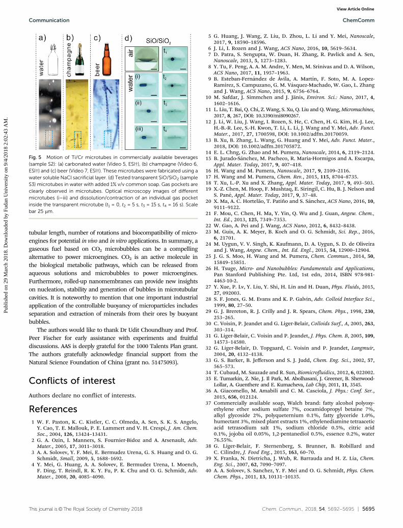
Carbon dioxide is a widely used gas in the beverage industry, andit provides a unique approach for powering and testing micro-engines in various chemical conditions. We tested the motion ofTi/Cr microengines in commercially available sparkling water, beerand champagne as shown in Fig. 5(a–c) and Videos 5–7, ESI.† Toprove our hypothesis about the existence of gas pockets in micro-tubes, we fabricated transparent rolled-up SiO/SiO2 dried tubesconsisting of nanomembranes (sample S3), Fig. 5(d). Air gas pocketswith different sizes and positions trapped inside microtubes whenthe sample was immersed in DI water (Fig. 5(d), (i–iii)). Moreover, ifthe sample was left in water without the addition of CO2, the gaspockets dissolved in minutes (Fig. 5(d), t1–t4, Video 8, ESI†). Thisindicated that an immediate addition of a carbon dioxide-containing gaseous fuel is required to activate the generation ofbubbles and keep the gas pockets stable. We have reserved futureresearch on effects of surface hydrophobicity, surface roughness,
Fig. 3 Pre-tests of Ti/Cr microengines integrated on-chip in differentconcentrations of surfactants (sample S1). (a) Optical microscopy imagesindicating CO2 bubble detachment radius controlled by surfactants(common soap) in carbonated water: c1 (0%, DI CO2 water), c2 (1% v/v,CO2 water) and c3 (10% v/v, CO2 water). Scale bar 400 mm. (b) Bubbledetachment radius as a function of surfactant concentration.
Fig. 4 Magnetic control of individual ferromagnetic Ti/Fe/Cr microtube(sample S2). (a) Slow sedimentation of microtube in carbonated water wasobserved. (b) Graph shows external magnetic control to rotate the micro-tube to 901, which changes its weight-buoyancy ratio while keeping anaverage bubble frequency 16 Hz invariant with respect to the angle ofrotation (0–901). Arrow bars in (a–c) indicate the direction of the micro-tube motion. (d) The velocity of the microtube is changed within secondswhen the tube is rotated using magnetic field. The inset image shows aschematic of the microtube external control. The external magnet waskept at a further distance to allow microtube rotation and avoid magneticattraction (Video 4, ESI†).
ChemComm Communication
Publ
ishe
d on
29
Mar
ch 2
018.
Dow
nloa
ded
by F
udan
Uni
vers
ity o
n 9/
4/20
18 2
:02:
43 A
M.
View Article Online
This journal is©The Royal Society of Chemistry 2018 Chem. Commun., 2018, 54, 5692--5695 | 5695
tubular length, number of rotations and biocompatibility of micro-engines for potential in vivo and in vitro applications. In summary, agaseous fuel based on CO2 microbubbles can be a compellingalternative to power microengines. CO2 is an active molecule inthe biological metabolic pathways, which can be released fromaqueous solutions and microbubbles to power microengines.Furthermore, rolled-up nanomembranes can provide new insightson nucleation, stability and generation of bubbles in microtubularcavities. It is noteworthy to mention that one important industrialapplication of the controllable buoyancy of microparticles includesseparation and extraction of minerals from their ores by buoyantbubbles.
The authors would like to thank Dr Udit Choundhury and Prof.Peer Fischer for early assistance with experiments and fruitfuldiscussions. AAS is deeply grateful for the 1000 Talents Plan grant.The authors gratefully acknowledge financial support from theNatural Science Foundation of China (grant no. 51475093).
Conflicts of interest
Authors declare no conflict of interests.
References1 W. F. Paxton, K. C. Kistler, C. C. Olmeda, A. Sen, S. K. S. Angelo,
Y. Cao, T. E. Mallouk, P. E. Lammert and V. H. Crespi, J. Am. Chem.Soc., 2004, 126, 13424–13431.
2 G. A. Ozin, I. Manners, S. Fournier-Bidoz and A. Arsenault, Adv.Mater., 2005, 17, 3011–3018.
3 A. A. Solovev, Y. F. Mei, E. Bermudez Urena, G. S. Huang and O. G.Schmidt, Small, 2009, 5, 1688–1692.
4 Y. Mei, G. Huang, A. A. Solovev, E. Bermudez Urena, I. Moench,F. Ding, T. Reindl, R. K. Y. Fu, P. K. Chu and O. G. Schmidt, Adv.Mater., 2008, 20, 4085–4090.
5 G. Huang, J. Wang, Z. Liu, D. Zhou, L. Li and Y. Mei, Nanoscale,2017, 9, 18590–18596.
6 J. Li, I. Rozen and J. Wang, ACS Nano, 2016, 10, 5619–5634.7 D. Patra, S. Sengupta, W. Duan, H. Zhang, R. Pavlick and A. Sen,
Nanoscale, 2013, 5, 1273–1283.8 Y. Tu, F. Peng, A. A. M. Andre, Y. Men, M. Srinivas and D. A. Wilson,
ACS Nano, 2017, 11, 1957–1963.9 B. Esteban-Fernandez de Avila, A. Martın, F. Soto, M. A. Lopez-
Ramirez, S. Campuzano, G. M. Vasquez-Machado, W. Gao, L. Zhangand J. Wang, ACS Nano, 2015, 9, 6756–6764.
10 M. Safdar, J. Simmchen and J. Janis, Environ. Sci.: Nano, 2017, 4,1602–1616.
11 L. Liu, T. Bai, Q. Chi, Z. Wang, S. Xu, Q. Liu and Q. Wang, Micromachines,2017, 8, 267, DOI: 10.3390/mi8090267.
12 J. Li, W. Liu, J. Wang, I. Rozen, S. He, C. Chen, H. G. Kim, H.-J. Lee,H.-B.-R. Lee, S.-H. Kwon, T. Li, L. Li, J. Wang and Y. Mei, Adv. Funct.Mater., 2017, 27, 1700598, DOI: 10.1002/adfm.20170059.
13 B. Xu, B. Zhang, L. Wang, G. Huang and Y. Mei, Adv. Funct. Mater.,2018, DOI: 10.1002/adfm.201705872.
14 E. L. Chng, G. Zhao and M. Pumera, Nanoscale, 2014, 6, 2119–2124.15 B. Jurado-Sanchez, M. Pacheco, R. Maria-Hormigos and A. Escarpa,
Appl. Mater. Today, 2017, 9, 407–418.16 H. Wang and M. Pumera, Nanoscale, 2017, 9, 2109–2116.17 H. Wang and M. Pumera, Chem. Rev., 2015, 115, 8704–8735.18 T. Xu, L.-P. Xu and X. Zhang, Appl. Mater. Today, 2017, 9, 493–503.19 X.-Z. Chen, M. Hoop, F. Mushtaq, E. Siringil, C. Hu, B. J. Nelson and
S. Pane, Appl. Mater. Today, 2017, 9, 37–48.20 X. Ma, A. C. Hortelao, T. Patino and S. Sanchez, ACS Nano, 2016, 10,
9111–9122.21 F. Mou, C. Chen, H. Ma, Y. Yin, Q. Wu and J. Guan, Angew. Chem.,
Int. Ed., 2013, 125, 7349–7353.22 W. Gao, A. Pei and J. Wang, ACS Nano, 2012, 6, 8432–8438.23 M. Guix, A. K. Meyer, B. Koch and O. G. Schmidt, Sci. Rep., 2016,
6, 21701.24 M. Uygun, V. V. Singh, K. Kaufmann, D. A. Uygun, S. D. de Oliveira
and J. Wang, Angew. Chem., Int. Ed. Engl., 2015, 54, 12900–12904.25 J. G. S. Moo, H. Wang and M. Pumera, Chem. Commun., 2014, 50,
15849–15851.26 H. Tsuge, Micro- and Nanobubbles: Fundamentals and Applications,
Pan Stanford Publishing Pte. Ltd, 1st edn, 2014, ISBN 978-981-4463-10-2.
27 Y. Xue, P. Lv, Y. Liu, Y. Shi, H. Lin and H. Duan, Phys. Fluids, 2015,27, 092003.
28 S. F. Jones, G. M. Evans and K. P. Galvin, Adv. Colloid Interface Sci.,1999, 80, 27–50.
29 G. J. Brereton, R. J. Crilly and J. R. Spears, Chem. Phys., 1998, 230,253–265.
30 C. Voisin, P. Jeandet and G. Liger-Belair, Colloids Surf., A, 2005, 263,303–314.
31 G. Liger-Belair, C. Voisin and P. Jeandet, J. Phys. Chem. B, 2005, 109,14573–14580.
32 G. Liger-Belair, D. Topgaard, C. Voisin and P. Jeandet, Langmuir,2004, 20, 4132–4138.
33 G. S. Barker, B. Jefferson and S. J. Judd, Chem. Eng. Sci., 2002, 57,565–573.
34 T. Cubaud, M. Sauzade and R. Sun, Biomicrofluidics, 2012, 6, 022002.35 E. Tumarkin, Z. Nie, J. Il Park, M. Abolhasani, J. Greener, B. Sherwood-
Lollar, A. Guenthere and E. Kumacheva, Lab Chip, 2011, 11, 3545.36 A. Giacomello, M. Amabili and C. M. Casciola, J. Phys.: Conf. Ser.,
2015, 656, 012124.37 Commercially available soap, Walch brand: fatty alcohol polyoxy-
ethylene ether sodium sulfate 7%, cocamidopropyl betaine 7%,alkyl glycoside 2%, polyqueternium 0.1%, fatty glyceride 1.0%,humectant 3%, mixed plant extracts 1%, ethylenediamine tetraaceticacid tetrasodium salt 1%, sodium chloride 0.5%, citric acid0.1%, jojoba oil 0.05%, 1,2-pentanediol 0.5%, essence 0.2%, water76.55%.
38 G. Liger-Belair, F. Sternenberg, S. Brunner, B. Robillard andC. Cilindre, J. Food Eng., 2015, 163, 60–70.
39 X. Franka, N. Dietricha, J. Wub, R. Barrauda and H. Z. Lia, Chem.Eng. Sci., 2007, 62, 7090–7097.
40 A. A. Solovev, S. Sanchez, Y. F. Mei and O. G. Schmidt, Phys. Chem.Chem. Phys., 2011, 13, 10131–10135.
Fig. 5 Motion of Ti/Cr microtubes in commercially available beverages(sample S2): (a) carbonated water (Video 5, ESI†), (b) champagne (Video 6,ESI†) and (c) beer (Video 7, ESI†). These microtubes were fabricated using awater soluble NaCl sacrificial layer. (d) Tested transparent SiO/SiO2 (sampleS3) microtubes in water with added 1% v/v common soap. Gas pockets areclearly observed in microtubes. Optical microscopy images of differentmicrotubes (i–iii) and dissolution/contraction of an individual gas pocketinside the transparent microtube (t1 = 0, t2 = 5 s, t3 = 15 s, t4 = 16 s). Scalebar 25 mm.
Communication ChemComm
Publ
ishe
d on
29
Mar
ch 2
018.
Dow
nloa
ded
by F
udan
Uni
vers
ity o
n 9/
4/20
18 2
:02:
43 A
M.
View Article Online