arc flash boundary
DESCRIPTION
FlashTRANSCRIPT

ARC Flash Boundary
Arc Flash Boundary (ARC) - is the distance at which an electrical arc can flashoutward, which may endanger employees working on electrical equipment.
Flash Protection Boundary (FPB) – the calculated safe working distance fromelectrical equipment which would not expose the employee to the hazardsassociated with an electrical arc flash.
Approach / Protection BoundariesThe National Fire Protection Association (NFPA) has developed specific approach boundariesdesigned to protect employees while working on or near energized equipment. Theseboundaries are:
Flash Protection Boundary (outer boundary) Limited Approach Restricted Approach Prohibited Approach (inner boundary)
Flash Protection Boundary (outer boundary): The flash boundary is the farthest established boundary from the energy source. If an arc flash occurred, this boundary is where an employee would be exposed to a curable second degree burn (1.2 calories/cm2). The issue here is the heat generated from a flash that results in burns.
Limited Approach: An approach limit at a distance from an exposed live part where a shock hazard exists.
Restricted Approach: An approach limit at a distance from an exposed live part which there is an increased risk of shock.
Prohibited Approach (inner boundary): A distance from an exposed part which is considered the same as making contact with the live part.

Understanding the Arc Flash Warning LabelsEach piece of equipment operating at 50 volts or more and not put into a deenergized state must be evaluated for arc flash and shock protection. This evaluation will determine the actual boundaries (i.e. prohibited, limited, restricted etc) and will inform the employee of what PPE must be worn.Once the evaluation is complete an Arc Flash Hazard warning label must be affixed to the equipment and readily accessible to employees who may work on the energized equipment.
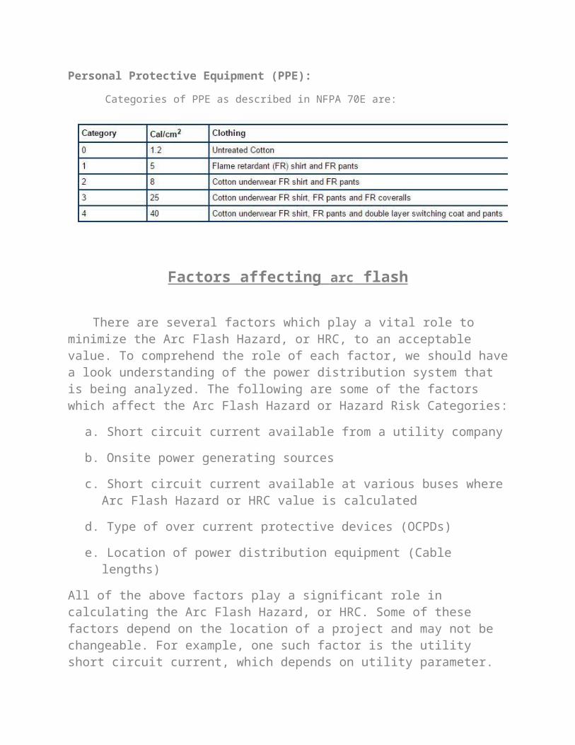
Personal Protective Equipment (PPE):
Categories of PPE as described in NFPA 70E are:
Factors affecting arc flash
There are several factors which play a vital role to minimize the Arc Flash Hazard, or HRC, to an acceptable value. To comprehend the role of each factor, we should have a look understanding of the power distribution system that is being analyzed. The
following are some of the factors which affect the Arc Flash Hazard or Hazard Risk Categories:
a. Short circuit current available from a utility company
b. Onsite power generating sources
c. Short circuit current available at various buses where Arc Flash Hazard or HRC value is calculated
d. Type of over current protective devices (OCPDs)
e. Location of power distribution equipment (Cable lengths)
All of the above factors play a significant role in calculating the Arc Flash Hazard, or HRC. Some of these factors depend on the location of a project and may not be changeable. For example, one such factor is the utility short circuit current, which depends on utility parameter. These parameters may have been chosen by the utility’s engineer long before the inception of this project and now these are unalterable.
Utility fault current contribution affect short circuit values at various buses throughout the power distribution system. If the available short circuit current is
higher from a utility, the calculated short circuit values at various buses would also be higher. The Arc Flash Hazard, or HRC, depends on a calculated short circuit
current value. When the calculated short circuit value is higher, HRC may be low or vice a versa, so this relationship is inversely proportional.
Arc flash protective devicesThe short circuit current has a very vital role in calculating Arc Flash Hazard or HRC. The short circuit current (Isc) is interrupted by an OCPD, therefore we need to understand the behavior of these devices. In this article we are considering only low voltage (600 volts below) OCPDs. In general, there are two types of OCPDs namely:
I. Fuses and
II. Circuit breakers
Fuse: A device that protects a circuit by fusing open its current-responsive element when an over-current passes through it. An over-current is either due to an overload or a short circuit condition.
The Underwriter Laboratories (UL) classifies fuses by letters e.g. class CC, T, K, G, J, L, R, and so forth. The class letter may designate interrupting rating, physical dimensions, and degree of current limitation.
As per NEC [1] and ANSI/IEEE standard 242 [2] - A current limiting fuse is a fuse that will interrupt all available currents above its threshold current and below its maximum interrupting rating, limit the clearing time at rated voltage to an interval equal to or less than the first major or symmetrical loop duration, and limit peak let-through current to a value less than the peak that would be possible with the fuse replaced by a solid conductor of the same impedance.
Molded Case Circuit Breaker (MCCB): It has either a thermal magnetic trip unit or a micro process based solid state trip unit. Both of these trip units provide over load and short circuit protection. Solid state trip unit is more flexible and provide more precise protection. Its trip characteristics are more precise and adjustable.
Insulated Case Circuit Breaker (ICCB): Although this type of breaker falls under UL 489 yet these breakers are different from standard molded case circuit breakers. In general these breakers have large frame size, a typical ICCB starts with 800 ampere frame and its upper range ends at 4000 ampere or higher.
An ICCB has a stored energy mechanism and energy can be stored either manually or by an electric motor. This type of breaker has micro process based trip unit with great precision and flexibility. An ICCB provides overcurrent protection and its trip characteristics are adjustable. A standard ICCB comes with long time pick up, long time delay and instantaneous trip features. Some optional features are also available e.g. short
time pickup, short time delay, ground fault pickup and ground fault delay with I2t in or out.