aqueous technologies trident batch cleaner - installation ... · aqueous technologies trident batch...
TRANSCRIPT

Aqueous Technologies Trident Batch Cleaner -
Installation & Training Guide
J.D. Noble & Associates, Inc. 720 Industrial Drive, Unit 118
Cary, IL 60013
Phone: 847.639.2440 Fax: 847.639.2489
Website: www.jdnoble.com E-mail: [email protected]

Section 1: Introduction
The Aqueous Technologies Trident system is a PC-Controlled, Aqueous Cleaning System designed to
remove flux residues and other various soils, from the surfaces of Printed Circuit Boards and assemblies.
Aqueous Technologies has been building batch format defluxing systems for over 22 years and is located
in the environmental epicenter of North America, Southern California. Therefore they have been at the
forefront in designing defluxing systems that are both effective and environmentally friendly.
The Theory of Operation of the Trident system is a 3-phase process: Wash, Rinse then Dry. The Wash
stage is meant to solubilize the flux soil which may/may not require the use of chemistry depending on
the flux soils to be removed. After the Wash stage, there is a series of Rinse cycles with each Rinse cycle
using a fresh supply of DI water to rinse the PCBs. After the Rinse discharge passes a resistivity check
the system proceeds to a Dry cycle (see Fig 1.1: Predictive Cleanliness Control for a step chart of the
Rinse process).
It should be clarified however that the Predictive Cleanliness Control function is not a cleanliness tester,
but rather it is simply a process monitoring tool to help predict your PCB cleanliness. The function is not
capable of testing individual boards, but only the presence of ionic contamination in the rinse discharge.
This is assuming that the chemistry has solubilized the flux and soils and the rinse cycles have evacuated
them from the wash chamber during the rinse cycles.
To achieve an actual cleanliness level you should resort to other tests such as Resistivity Of Solvent
Extract (R.O.S.E.) or Ionic Chromatography. The more common and practical is the R.O.S.E. Test;
however, the more accurate and costly is Ionic Chromatography. Typically users will contract out to
have the Ionic Chromatography tests performed as needed.

Section 2: Machine Configuration
The Aqueous Technologies Trident systems come in several different configurations; from single-
chamber to multi-chamber systems to limited-discharge to closed-loop systems.
Multi-chamber systems can either increase your throughput or give you flexibility in your process. You
can configure each chamber the same to provide you with a higher throughput capacity or you can have
each chamber configured differently to maximize your process flexibility.
The Trident multi-chamber system is available in 4 different configurations: Single, Duo, Trio and Quad.
The Trident has 3 different plumbing configurations: Trident-LD, Trident-XLD and Trident-CL.
The main two considerations for which configuration are whether chemistry may be required and how
the system will handle the discharge.
2.1 - Trident Models:
Figure 2.1: Trident-LD Figure 2.2: Trident-XLD
Trident-LD (see Figure 2.1: Trident-LD): This is the most common configuration of the
equipment. The Trident-LD is a Limited Discharge system. It incorporates a “closed-loop” wash cycle
where it incorporates a wash solution chamber for storage of the wash solution after the wash cycle.
The wash system then rinses the PCBs (approx. 6-10 times) and the rinse effluent is sent to drain.
Compliance with any local municipal codes is required in this configuration.

This configuration is capable of using Chemistry (if required) and cleaning No Clean and Water
Soluble flux soils.
NOTE: If cleaning Water Soluble flux soils without chemistry you would want to have a Fresh
Water Wash cycle selected in your recipe.
Trident-XLD (See Fig 2.1: Trident-XLD): This configuration has become increasingly popular in
recent time due to the increasing restrictions/risks of effluent discharge. The system is configured with
an EcoCycler rinse water recycling system which recirculates and polishes the water as required. The
EcoCycler is both the supply and the drain for the Trident which creates a closed-loop (Zero Discharge)
configuration. All of the discharge is filtered by the EcoCycler and its Carbon/Resin DI Tank System.
This configuration is capable of using Chemistry (if required) and cleaning No Clean and Water
Soluble flux soils.
NOTE: If cleaning Water Soluble flux soils without chemistry you would want to have a Fresh
Water Wash cycle selected in your recipe.
Trident-CL: The system is configured as a closed-loop (Zero Discharge) configuration. It incorporates
the use of DI filtration directly into the machine itself. Due to this the machine is not compatible with
chemistry and can only be used on Water Soluble flux soils.
This configuration is NOT capable of using Chemistry and cleaning Water Soluble flux soils only.
2.2 - Internal Parts Descriptions and
Definitions:
Wash Chamber: Chamber used for the loading of
Printed Circuit Boards. This is the chamber where
the Wash, Rinse and Dry Processes are
performed.
Sump Tank: This is a 3.5 gallon tank that is
mounted directly under the bottom of the wash
chamber, where the Wash/Rinse water is
collected and heated (as required).

Wash Solution Tank: This is a 12 gallon holding tank for
your wash solution. This tank is NOT heated; however,
over the course of the day it will increase in temperature
as the heated wash solution is returned to the wash
solution tank after completion of the wash process.
Chemistry Concentrate Tank: This is an 8 gallon holding
tank for storing your chemistry in a concentrated form
for mixing via the Dosatron.
Dosatron: The Dosatron is a mechanical mixing system
that allows for easy chemistry management by dial
control of your chemistry concentration percentage.
The system allows for the appropriate mixing of
incoming DI water from your incoming supply with the
concentrated chemistry in the 8 gallon Chemistry
Concentrate Tank for disbursement into the 12 gallon
Wash Solution tank.
Drain Filter: The drain filter is a 20 micron filter prior to sending any material to the drain.

Section 3: Facilities
Electrical:
Depending on the configuration of your system your electrical power to the unit may vary, but in most
instances in North America we are operating on a 208 or 240 VAC, 3 phase configuration. The
amperage will vary depending on the quantity of chambers (Single, Duo, Trio or Quad).

You will need to verify that you have the proper phase rotation on your electrical service BEFORE you
energize your water pumps. In order to verify the proper phase rotation you will need to verify that the
blower is spinning in the proper direction (counter-clockwise). To
do this, perform the following steps:
1. Turn On Power to the system
2. Turn On Power to the PC
3. Remove the Inlet Air Filter from the back of the Trident
4. From the Main Screen press “Program Setup”
5. Login with the Administrator Password: ADMIN
6. Press the “Manual Device Control” button on the right
side of the Administrator Setup screen
7. Ensuring the blower is clear, quickly Turn On the Blower
by pressing the “Blower” button
8. Immediately Turn Off the Blower by pressing the “Blower”
button a 2nd time.
9. Wait for the blower to slow down and observe the
direction of rotation
10. If it is Counter-Clockwise then you can proceed with the
installation.
11. If it is Clockwise you have improper phase rotation and
will need to transpose any two legs of the incoming power
to the machine.
NOTE: Insure that the computer is shut down and power
is disconnected before performing this work.

Deionized Water (DI Water)
In order to properly clean PCBs you will need a quality source of DI water. This source can be either a DI
tank system that is filtering incoming city water or it can be water provided by the EcoCycler system.
Deionized water is water that is run through a resin bed that filters out the ionic charge of water,
typically found in mineral salts in the water. Deionized water has a higher resistance to electrical
current than your standard tap water due to the removal of these ions. This is beneficial to the cleaning
of PCBs in two distinct ways:
It does not create a short on PCB itself due to the resistivity to current
Due to the nature of the water to “re-ionize” itself, it makes for a good cleaning agent as it
attracts the ionic contamination on the board in the form of the flux and other soils
Deionized Water quality is measured by its resistivity to an electrical current. High quality DI water will
be highly resistant and give you a higher resistivity reading, measured in kΩ or mΩ; whereas water that
is loaded with ionic contamination will carry a very low resistance to the electrical current; therefore the
readings could be all the way down to 0 at which point it is acting like a conductor.
General guidelines for what level of DI water our process requires are as follows:
Optimal: > 10 mΩ
Standard: 4-10 mΩ
Minimum: 2 mΩ
Ventilation
Generally speaking, minimal chemicals are being ventilated into the air via the vent stack; however
there will be some presence of odor of the chemistry. Ideally your process is optimized to the point that
you are conserving as much chemistry as possible and that very little has been left in the wash chamber.
Furthermore, through the thorough rinse process and the active resistivity test of the discharge there
should be very little chemistry being evacuated via the exhaust during the drying process. However,
best practice tells us to eliminate the possibility by properly exhausting the system.
In doing so, you will find two different kinds of systems: active and static. Active systems have a
fan/blower system that is actively pulling the exhaust out through the vent stack. Static is simply an air
exhaust vent that is depending on the blower from the Trident system to evacuate the exhaust.
There are several considerations that need to be considered before exhausting your Trident and depeing
on your exhaust system type.
Active Exhaust Systems: When incorporating your cleaner into “Active” exhaust system, you
should leave a gap between the Trident exhaust pipe and the Ventilation system pipe. When an active

system is hooked directly to the Trident system, without a gap, it can cause premature evaporation of
the Wash Solution in the Wash Solution tank.
Static Ventilation System: In a static ventilation system, the Trident Vent stack will be hooked directly to
the vertical ventilation stack. Between the Trident Vent stack and the facility vent stack you should
install a damper so that the valve opens outwards.
TIP: If you tack down one side of the damper it will maintain a better positive pressure in the
chamber, this can be extremely helpful, especially during the dry cycle insuring that the PCBs dry faster
and more efficiently.

Section 4: System Initialization
You may have already performed some of the following tasks in previous sections and if you are sure
they have been performed you can proceed to the next step. Beyond that this next section will direct
you on how to initialize the system for the first time.
1. Verify Electrical Phase Rotation
2. Verify Plumbing Connections
a. Trident-LD
i. Incoming Water: DI Tank System
ii. Discharge: Drain
b. Trident-XLD
i. Incoming Water: EcoCycler
ii. Discharge: EcoCycler
c. Trident-CL
i. Incoming Water: Inlet ← Resin Tank
ii. Discharge: Outlet → Carbon Tank
3. If running a Trident-XLD, initialize the EcoCycler…if not proceed to Step 4
a. Verify EcoCycler Plumbing Connections
i. Outlet → Water Inlet on Trident
ii. Inlet ← Primary Drain on Trident
iii. Outlet → Carbon Tank
iv. Inlet ← Resin Tank
b. Verify Electrical Power – 110V
c. Open Supply Valve from facility
d. Verify all valves on EcoCycler are open (except any DI Access points for sampling
purposes)
e. Verify water flow into system
f. Prime the pump
i. Locate the pump in the lower front access panel of the EcoCycler
ii. Loosen the hex bolt on top of the pump

iii. Observe for water droplets at the hex bolt
iv. Immediately tighten the hex bolt
g. On the EcoCycler control panel, turn the Power switch (Green) On
h. On the EcoCycler control panel, turn the System switch (Red) On
i. Open the Right-Hand access panel on the EcoCycler and open the lid to the recirculation
chamber
j. On the inside of the recirculation chamber, towards the rear of the machine you will see
a vertical stem with a red handled ball valve
k. Close this valve approximately 50% and observe the water pressure displayed on the
Facility Pressure gauge on the Trident (Target Range = 30-35 PSI)
l. Increase/Decrease as necessary, where closing the valve increases the water pressure
and opening the valve decreases the pressure.
m. Let the system circulate until an adequate quality DI water is achieved
4. Loading the Wash Solution chamber
a. Load Concentrated Chemistry tank with the desired chemistry
b. Set the desired concentration % by rotating the sleeve until the desired concentration
level
c. Prime the Dosatron
i. Locate the bleeding nipple on top of the Dosatron

ii. Depress and hold the bleeding nipple on the Dosatron
iii. Activate the Add Wash Solution switch
iv. Observe for water droplets at the bleeding nipple
v. When water droplets appear, release the bleeding nipple
vi. Proceed to Step iv
d. Fill the Wash Solution tank approximately 50%
e. Deactivate the Add Wash Solution switch
f. Mix the Wash Solution tank (Manually or via the Mixer in the Wash
Solution Chamber)
g. Verify concentration in the wash solution tank with a recommended test
procedure for the desired chemistry
h. Adjust the Dosatron as necessary
i. Manually add chemistry to the Wash Solution Tank if necessary or dilute
with the “Add Water” switch
j. Fill the Wash Solution tank to the top
k. Mix the Wash Solution tank (Manually or via the Mixer in the Wash
Solution Chamber)
l. Verify concentration in the wash solution tank with a recommended test
procedure for the desired chemistry
Section 5: Software
Within the Aqueous Technologies Trident Software you will find 3 screens:
Main Screen
Recipe Editor Screen
Administrator Menu

Main Screen
The Main Screen is the initial screen displayed upon initialization of the Trident software. This screen
allows you to see various pieces of information, including the current recipe information, operational
devices and the expected cycle start\finish times.
Also on the Main Screen is the Program Setup button. This button is your portal to the various menus
throughout the program. Depending on what password you enter when click “Program Setup”, will
determine what screen is loaded.
The default passwords are SUPER for the Recipe Editor Menu and ADMIN for the Administrator Menu.

Recipe Editor Page
Programming a recipe with the Trident is simple and easy. You can either modify an existing recipe or
you can add a new recipe from scratch. Many customers have a general recipe for their standard PCBs
and an assortment of serialized recipes for their more challenging cleaning applications. You can also
program custom recipes, such as a Rinse/Dry Only, or a Dry Only.
To program a recipe you will need to set the following items: Wash Time, Wash Temp, Use Fresh Water
Wash, Rinse Temp (Enable/Disable), Total Rinses, Cleanliness (kΩ) (Enable/Disable), Dry Time, Dry Temp
and Disable Chamber Heater.
You can modify each setting via the slide dial or you can tap on the setting button which will bring up a
numeric keypad to enter the data directly.
Depending largely on your flux, soils and board size/layout will determine your recipe. Please refer to
the chart for some generic recipes for both No Clean and Water Soluble flux residues.

Operating w/ Chemistry: No Clean (NC) and Water Soluble (OA) Flux Residues
Wash
Temp (F)
Wash
Time
(Minutes)
Fresh
Water
Wash
Rinse
Temp (F)
Total
Rinses
Cleanliness
(kΩ)
Dry Time
(Minutes)
Dry Temp
(F)
6-10 130-150 NO - 6-8 200-400 12-15 160-170
Operating w/o Chemistry: Water Soluble (OA) Flux Residues
Wash
Temp (F)
Wash
Time
(Minutes)
Fresh
Water
Wash
Rinse
Temp (F)
Total
Rinses
Cleanliness
(kΩ)
Dry Time
(Minutes)
Dry Temp
(F)
2-3 130-150 YES - 6-8 200-400 12-15 160-170
Recipe Definitions:
Wash Temp (F) – the temperature that the wash solution is heated to in the 3.5 gallon sump
tank for use during the Wash Stage.
Wash Time (Minutes)– the duration of the Wash Stage.
Fresh Water Wash – the definition of requiring fresh DI water from the facility for the Wash
Stage which essentially bypasses the Wash Solution tank. This is primarily used when cleaning Water
Soluble (OA) fluxes without using a chemistry.
Rinse Temp (F) – the temperature to what each Rinse Cycle is heated in the 3.5 gallon sump
tank. Generally we use ambient rinse temperature due to the impact on cycle time of heating each
rinse.
Total Rinses – this is the max rinse count the system will run, regardless of whether it achieved
the cleanliness level that was set.

Cleanliness (kΩ) – this is the resistivity level to be achieved during the Rinse Cycles before
ending the Rinse process.
Dry Time (Minutes) – the duration of the Dry Cycle of the machine.
Dry Temp (F) – this is the temperature at which the boards are dried in the chamber after
completion of the process.
Section 6: Operation
Opening the Chamber
The chamber is equipped with a mechanical lock to prevent premature release and exposure to the
steam and heat that has built up inside the wash chamber during the Wash Cycle. The door lock is
programmed to remain locked for approximately 40-60 seconds after completion of a Wash Cycle.
Once it is passed this programmed Cooldown stage you can press and hold the button until the lock
releases and allows you to open the chamber. You should still show caution as the chamber will still be
hot, and care should be taken when handling the PCBs or contacting the metal board rack.
NOTE: In case of power loss or emergency chamber access, there is a small pinhole where you can
manually override the door lock and access the chamber.

Board Loading
Care and consideration needs to be taken when loading the Trident. To maximize you throughput
common thought is to load as many boards as possible into the wash chamber; however, you need to
make sure that you do not overload the chamber. If you overload the chamber you will have problems
with PCBs shadowing others from spray impingement and this will have an overall impact on the
cleanliness of the finished product.
Also considering PCB orientation when load the boards is paramount to success. Many boards have
connectors and if you insert the boards so that gravity assists in the draining procees, you will improve
the drying capabilities of the equipment. Basically try to load all the PCBs so that the connectors face
downwards so that any residual water naturally drains out.
aSPC Data Entry
If you have activated the aSPC data option in the Administrator Menu, you will be able to enter serial
information on your PCBs along with operator information for SPC data collection. If you have a
compatible bar code scanner hooked up you will be able to scan the barcodes and enter them directly as
you load the machine.
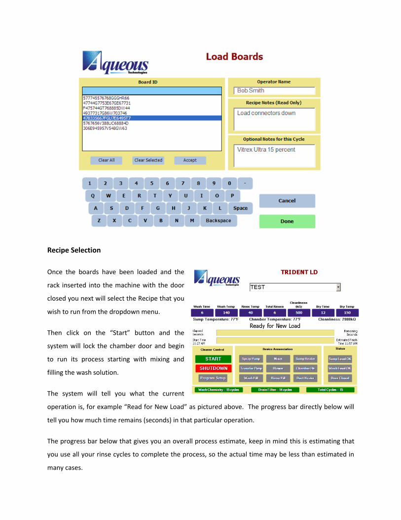
Recipe Selection
Once the boards have been loaded and the
rack inserted into the machine with the door
closed you next will select the Recipe that you
wish to run from the dropdown menu.
Then click on the “Start” button and the
system will lock the chamber door and begin
to run its process starting with mixing and
filling the wash solution.
The system will tell you what the current
operation is, for example “Read for New Load” as pictured above. The progress bar directly below will
tell you how much time remains (seconds) in that particular operation.
The progress bar below that gives you an overall process estimate, keep in mind this is estimating that
you use all your rinse cycles to complete the process, so the actual time may be less than estimated in
many cases.

Cycle Completion
After the wash process completes and the boards have been washed, rinsed and dried you will get a
PASS or FAIL message on the screen. If the rinse drain achieves a resistivity greater than your set point
within the maximum quantity of rinses you programmed you will receive a green PASS message which
will also include the Resistivity Set point, the Actual Resistivity and Total Rinse Count.
Board Handling & Storage
You will want to use care and caution in handling the PCBs after washing. Be sure not to reintroduce
contamination to the PCBs, by ensuring that your hands are clean of oils, greases and salts (which
include typical lotions and soaps). Best practice is to where powder-free latex gloves when handling
clean PCBs, especially prior to a Zero Ion test as described in the next section.
You also do not want to store your boards directly underneath an air vent or any other source of
contamination that may disburse the contamination directly onto your freshly cleaned PCBs. You may
also wish to immediately package your clean PCBs into ESD bags for protection.
Test & Inspection
The first initial test method is visual inspection. Your PCBs should be clean, free of residue and the
solder joints should be bright and shiny. Observe any residual moisture and whether the moisture is
clear or white, residues on the PCBs or darkening of the solder joints.

Depending what is observed can give you an indication of any fine tuning on your process that may be
required, whether the chemistry is not being fully evacuated or if it simply requires more time in the Dry
Cycle.
You should have your boards audited by an external tester on a regular basis as defined by your quality
department. Most commonly this test is performed by a R.O.S.E. tester, such as the Aqueous
Technologies Zero Ion Contamination tester.
The basic theory of operation for R.O.S.E. test equipment is: a mixture of Isopropyl Alcohol (IPA) 75%/DI
Water 25% that uses the contamination extraction characteristics associated with IPA to extract any
contamination that maybe trapped on the PCB and a highly sensitive meter detects and measures the
volume of the contamination and this figure is divided by the square area of your PCB/PCA. The reading
you will receive is in a µg/in2 or µg/cm2 depending on which unit of measure you choose. General Ionic
Contamination Pass/Fail limits are as follows:
< 10 µg/in2
< 1.56 µg/cm2
R.O.S.E. testing is more practical for an everyday environment because it isn’t as expensive to operate as
other test methods and does not necessarily require a chemist to operate the test process. The process
can give you relatively immediate (~30 minutes) information on your cleaning process in comparison to
other test methods that have to be sent to a lab for analysis.
The drawback of R.O.S.E. testing is that it does not isolate exactly where on the PCB the contamination is
located. In contrary, the amount of contamination is divided across the PCB to give you a Pass/Fail. This
leaves the loophole that there could be a lot of contamination under one specific component but if the
board is large enough it will still pass, even though there is a potential for failure in the procedure,
Section 7: Maintenance
As with many systems there is a general maintenance routine for the Aqueous Technologies equipment.
The better you keep up with the maintenance schedule the longer and more efficiently your equipment

will function. In the following section we will highlight several maintenance items and their associated
schedule.
Maintenance Schedule
Daily
Drain Screen: ensure that the Drain Screen
is clear of any debris, labels, etc.
Wash Solution Level: Ensure that there is
enough Wash Solution in the Wash Solution.
Weekly
Chemistry Concentrate Level
Monthly
Inlet Air Filter
Drain Filter
Leakage in Plumbing
Spray Nozzles

Annually
Pump Seals
Perimeter & Lower Door Seals
Recommended Pressure Gauge Settings
The following gauges are the recommend pressure gauge settings on the Trident control panel.
About This Machine Screen
If you click on the Aqueous Technologies Logo in the Main Screen you will call up a menu with
operational information on the current system, including:
Model Number
Serial Number
Date Shipped
Customer Name
Software Version
Runtime Information: Air Heater, Sump Heater, Blower Motor, Chamber Heater and Spray Pump
Facility Water Pressure
30-35 PSI
This is the optimal
operating range for the
Trident system.
Nozzle Pressure
60-70 PSI
An increase or decrease
in pressure could be a
sign of a clogged or
missing spray nozzle.
Drain Pressure
0-35 PSI
This reading may vary,
but a high reading may
indicate a blockage in
the drain.
