april 23, 2010 mitsui chemicals, inc. shimonoseki mitsui ... local community and all other parties...
TRANSCRIPT
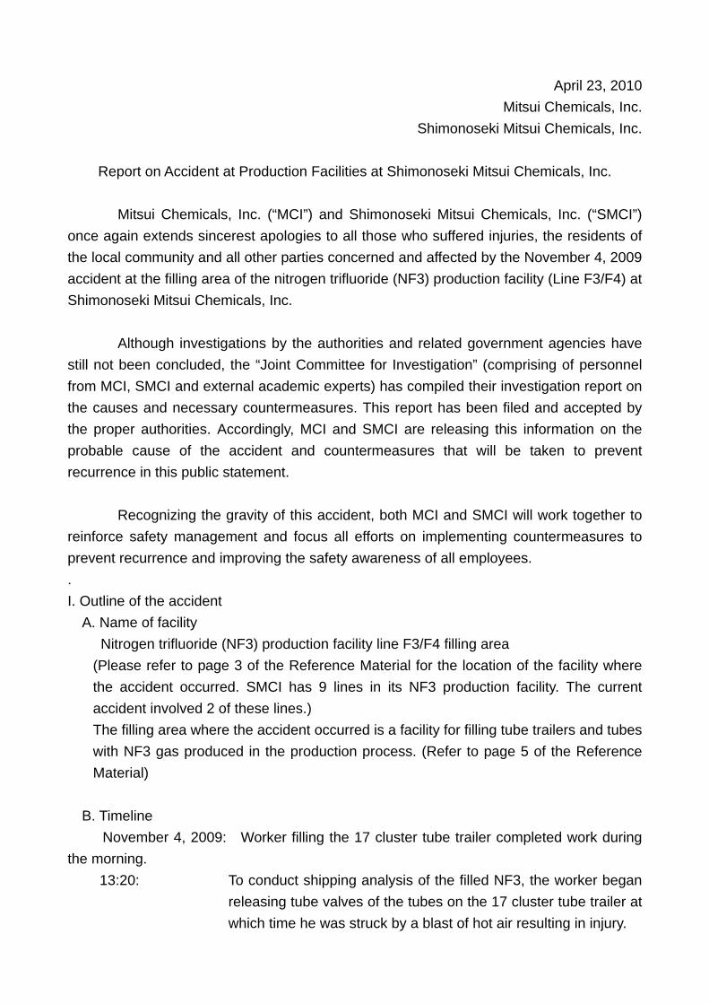
April 23, 2010 Mitsui Chemicals, Inc.
Shimonoseki Mitsui Chemicals, Inc.
Report on Accident at Production Facilities at Shimonoseki Mitsui Chemicals, Inc. Mitsui Chemicals, Inc. (“MCI”) and Shimonoseki Mitsui Chemicals, Inc. (“SMCI”) once again extends sincerest apologies to all those who suffered injuries, the residents of the local community and all other parties concerned and affected by the November 4, 2009 accident at the filling area of the nitrogen trifluoride (NF3) production facility (Line F3/F4) at Shimonoseki Mitsui Chemicals, Inc. Although investigations by the authorities and related government agencies have still not been concluded, the “Joint Committee for Investigation” (comprising of personnel from MCI, SMCI and external academic experts) has compiled their investigation report on the causes and necessary countermeasures. This report has been filed and accepted by the proper authorities. Accordingly, MCI and SMCI are releasing this information on the probable cause of the accident and countermeasures that will be taken to prevent recurrence in this public statement. Recognizing the gravity of this accident, both MCI and SMCI will work together to reinforce safety management and focus all efforts on implementing countermeasures to prevent recurrence and improving the safety awareness of all employees. . I. Outline of the accident A. Name of facility
Nitrogen trifluoride (NF3) production facility line F3/F4 filling area (Please refer to page 3 of the Reference Material for the location of the facility where the accident occurred. SMCI has 9 lines in its NF3 production facility. The current accident involved 2 of these lines.) The filling area where the accident occurred is a facility for filling tube trailers and tubes with NF3 gas produced in the production process. (Refer to page 5 of the Reference Material)
B. Timeline
November 4, 2009: Worker filling the 17 cluster tube trailer completed work during the morning.
13:20: To conduct shipping analysis of the filled NF3, the worker began releasing tube valves of the tubes on the 17 cluster tube trailer at which time he was struck by a blast of hot air resulting in injury.

13:23: The fire alarm and gas detector were triggered and the accident was confirmed by the central control room which contacted concerned divisions.
13:24: The in-house fire squad was called in and an emergency
response team was formed. The filling compressor was terminated and the Company commenced reporting the accident to concerned government agencies.
13:45: An explosion in the filling area sent debris (slate, insulation, tube
pieces, etc.) outside the confines of the Works, causing serious damage to surrounding areas. (Subsequently it was determined that the explosion originated from the 8 cluster tube trailer which was stored in the same filling area and not from the 17 cluster tube trailer itself. Debris found outside the Works was from this 8 cluster tube trailer.)
13:50 A second explosion occurred in the filling area.
Note: A tube trailer is a vehicle with multiple large gas cylinders (called tubes) used in transporting
gas. The tubes are connected using manifolds. (Refer to page 6 of the Reference Material)
The tube valve of a tube is that which is used to cut off each tube on the tube trailer from the
manifold. (Refer to page 10 of the Reference Material)
II. Injuries and damages (As of April 22, 2010) We extend sincerest apologies to the residents of the local community and all parties concerned for the injuries and damages listed below which resulted from this accident. A. Injuries
・ Nine local residents suffered bruises, cuts, sore throats, tinnitus, dizziness, etc. ・ One subcontractor employee suffered first degree burns on hands and face,
bruises ・ One employee suffered abrasions, sprains, rib hairline fracture ・ Current status: Treatment has been completed for eight persons. Three local
residents continue to receive out-patient treatment. B. Damages
・ Damage to homes and buildings: 100 ・ Damage to automobiles: 36 ・ Current status: All repairs and reimbursement have been completed for

damages to homes, buildings, and automobiles.
III. Probable cause of accident (Refer to pages 7 to 11 in the Reference Material) The “Joint Committee for Investigation” has determined the probable cause of the accident and proposes countermeasures to prevent recurrence. A. Cause of fire
After filling the 17 cluster tube trailer, the worker simultaneously released the main valves of all tubes to conduct NF3 gas analysis. It is probable that the differential pressure between the tubes caused high density, high volume NF3 to flow through the tube valve. The flow friction caused the temperature of the tube valve to rise. The rise in the tube valve temperature caused hot molten metal from the fusible plug to burst out with NF3 gas which was heated in the tube valve. It is assumed that the molten metal became a combustive source igniting the surrounding vinyl chloride curtains (flame retardant) to start the fire. Note: NF3 is an oxidizing gas that is stable at room temperature but becomes active when
exposed to heat or electricity.
Fusible plugs are safety devices that release contents of a tube when internal pressure
rises due to high temperatures by melting the enclosed fusible alloy and triggering the device.
B. Cause of tube explosion and scattering of debris
It is probable that fire occurring in the 17 cluster tube trailer spread to the tire of the 8 cluster tube trainer that was stored in the same filling area, heating the tube directly above the tire. This raised temperature inside the tube causing a reaction between NF3 and material of the tube. The pressure inside the tube increased rapidly and mechanical strength of the tube decreased causing the tube to explode.
IV. Measures to prevent recurrence (Refer to pages 12 to17 of the Reference Material)
The following countermeasures will be made to the seven lines other than lines F3 and F4 in consideration of the probable cause of the accident. Separate measures for lines F3 and F4 where the accident occurred, including the installation location, are being studied.
A. Prevention of fires
・Changes to filling procedures for the 17 cluster tube trailer such as simultaneous filling to avoid generating differential pressure among tubes will be made.

・Reinforcement of emergency shutdown system in the event of an anomaly ・Reinforcement of monitoring systems for early detection of anomalies
B. Prevention of spreading of fires ・Compartmentalization of filling area and removal of flammable materials ・Installation of sprinklers at the tube trailer filling facility We will provide details of these specific measures to the local residents to gain understanding as well as request directives from regulatory authorities to receive approval before resuming operations at the facility.
In addition to the abovementioned, MCI and SMCI will reinforce efforts to improve safety awareness of employees and workers by revising work guidelines to reflect the countermeasures including full explanation of the causes of the accident and training with regard to countermeasures.

Overview of Shimonoseki Mitsui Chemicals (SMCI)
SMCI plant is the birthplace of the ammonia and methanol industries in Japan, producing phosphoric acid, its derivatives, high purity gases for semiconductors, and specialty resins.
Establishment:Establishment: Oct 1st 2000 as SMCI
Headquarters & Plant:Headquarters & Plant: Shimonoseki
Sales branch:Sales branch: Tokyo
Site area:Site area: 450,000 m2
*SMCI is 100% owned by Mitsui Chemicals
Products:Products:- Phosphoric acid, Phosphate, Sodium fluorosilicateOEMOEM from MCI:from MCI:- Nitrogen trifluoride(NF3), Silicon tetrafluoride (SiF4)
for semiconductors- Formaldehyde- Specialty resins for adhesives, paper and textile Eco business:Eco business:- WARM (Waste Acid Recycle and Mud recycle) system
Reference Material
1

SiH4
Si Si
Si
F
F
F
NF3
Si Wafer
Plasma CVD ChamberSiF4
SiF4
SiF4
SiH4
Si Si
SiSiF4-based gas
Process for cleaning
SiH4
→ Si + 2H2
NF3
→ N + 3F
Si + 4F →
SiF4
Deposited Si
Plasma CVD
※Process
●NF3 is used to clean the CVD chamber→ NF3 reacts with Si deposited inside the chamber and removes the residue.
Image how to clean the chamber by NF3 plasma
Application for Nitrogen Trifluoride(NF3)
※CVD :
Chemical Vapor Deposition
2

総合計器室(全系制御)
F3/F4系製造工程
Filling area of Line F3/F4
Manufacturing area of Line F3/F4
Date : 2009/11/4
Time : 13:20~
Location: Filling area of Line F3/F4
*Capacity of area A was 30% of total.
Other LinesOther Lines <Independent and separated seven lines >
Incident Overview
3

Plot for F3 &F4 line
Storage AreaFilling Compressor
Electricity Room
Waste Water Tank
Industrial Water Tank
Manufacturing Area
F3
line
F4
line
F3 Line
Analyzing Room
Filling Area
F4 Line
4

Raw Material
Electrolytic Cells
Purification
Storage tank
Vaporizer
Filling Com
p.
Cylinder
チューブ
Tube Trailer
NH3
HF
NF3 Manufacturing Area NF3 Filling Area
Incident
NF3 Manufacturing Process
5

Front View
• Trailer to deliver the gases• It has several tubes and they are connected.
Side View
Rear View
What is Tube Trailer?
6

S S S S S S S SS S S S S
O
S SS SS→O
O O O O O O O OO O O O O O OO OO
O
Opened air valve to the tube valves→All tube valves were opened at once and
equalized the pressure between tubes
Valve for Air supply
Air
Air
Root cause : ‘Open all valves at once’
There was pressure differences between tubes because 2 or 3 tubes are filled per day
7

123456
789101112
1314151617
NF3 in the high pressure tube moved quickly in the manifold into the low pressure tube to equalize the pressure.
Higher pressure tubesLower pressure tubes
Tube valveManifold
For FillingFor Vacuum For supplying
Gas flow whenvalves were opened.
We had pressure difference between tubes because we filled 2 or 3 tubes each.
All tube valves were opened at once by supplying air
Image for ‘the gas flow when all valves were opened at once’
8

All tube valves were opened when there is pressure difference between tubes
Incident
Flow friction caused higher temp. • Stainless steel on the surface of flow route was
reacted with NF3• PCTFE around diaphragm seat was burned.• PCTFE packing around fusible plug was burned.
Burst #16 & #17 fusible plug
manifoldTube valve
Tube
Fusible plug
Gas flow (route)
High density NF3 flew through #16 and #17 valves with high flow
Mechanism of the fusible plug failure
9

To ManifoldTube Valve
Gas flow
Tube
Gas in the tube is released when tube/valve is heated by melting the fusible plug
Fusible Plug
Ref. What is tube valve and fusible plug
10

1. Melted metal of the fusible plug on the valve became the source of the fire.2. NF3 was supplied through burst plug to cause fire.3. Flame was ignited to the curtain which was made of PVC.4. Curtain was burned and fallen down.5. And it was ignited to the tire.6. Tire was burned, heated the tube and burst.
*NF3 assists to make flammable material fire as same as O2.
Mechanism of the tube burst
3
4
5
6
Under Storage Under filling/analyzing1
2
PVCCurtain
11

Before incident ; Fill separately
Countermeasures ; Fill all tubes at once
O O O O O O O O OO OO O O O
O
O O
4th
dayWe fill 2 or 3 tubes per day
1st
day 2nd
day 3rd
day
O O O O O O O O OO OO O O O
O
O O
S S S S S S O S SS SO S S S
O
S S
1st day
2nd day
*Same pressure all the time
*It is difficult to make all tubes same pressure
Safety measures : How to fill tube trailer w/o pressure difference
12

Safety measures : Strengthen emergency shut down system
Filling Compressor
Stop and isolate in an emergency
Install pneumatic valve between container and filling line to isolate in an emergency case
Isolate each tube by installing auto air-valve for 17 cluster tube trailer in an emergency case.
Isolate automatically when abnormal situation happens.
PI PI
T/T Filling header
13

場所移動
Newly installed
Ex. Filling area for F1/F2 line
Safety measures : Strengthen our monitoring system
Currently installed
Additional cameras in the tube trailer filling area are installed.
14

Filling Compressor
Filling Area
PI PI
We install pressure indicator between T/T filling header and T/T.* The pressure is monitored at control
room and filling area.
T/T Filling header
Safety measures : Strengthen our monitoring system
Pressure Indicator in the filling header is installed to record the pressure by computer.
15

Safety measures : How to prevent the fire spread
Items Current Future
Cover for filling/analyzing header PVC Remove
Partition between filling areas PVC Non-flammable materials
Partition between filling area and cylinder storage area PVC Metal
Ducts for process gas and air PVC Metal
Electricity cables N/A Protect by metal cover
① Plans to separate filling area and storage area. Additionally remove flammable materials from filling area
16

Filling Comp.
T/TFilling header
Sprinkler system for tires
Sprinkler system for tube trailer
【To minimize the source of fire】
Cool the manifold
【Prevent the fire】
Cool the tire
【To prevent the fire】
Cool the entire tubes
② Install sprinkler system in the tube trailer filling area
Safety measures : How to prevent the fire spread
17