analysis and design of integrated converter circuit … · abstract—in renewable energy sources...
TRANSCRIPT
Nov 2014 (Volume 1 Issue 6) JETIR (ISSN-2349-5162)
JETIR1406037 Journal of Emerging Technologies and Innovative Research (JETIR) www.jetir.org 565
Analysis and Design of Integrated Converter Circuit for
Renewable Energy and Drives Applications
1Hemapriya.S, 2Krishna Kumar.S 1PG Scholar-1st Year M.E (Control & Instrumentation), 2Project Engineer
1Ganadhypathi Tulsi’s Jain Engineering College, Vellore – Tamil Nadu, India 2Coretronix Labz, Vellore – Tamil Nadu, India
Abstract— In renewable energy sources such as photovoltaic (PV), wind, fuel cell, etc gain importance due to the limitations of
conventional energy sources. Renewable energy sources play an important role in rural areas where the power transmission from
conventional energy sources is difficult. Other advantages of renewable energy sources are clean, light and does not pollute atmosphere.
In order to meet the required load demand, it is better to integrate the renewable energy sources with the load. Hybrid electric vehicles
(HEVs) powered by electric machines and an internal combustion engine (ICE) are a promising mean of reducing emissions and fuel
consumption without compromising vehicle functionality and driving performances. The proposed integrated circuit allows the
permanent magnet synchronous motor to operate in motor mode or acts as boost inductors of the boost converter, and thereby boosting
the output torque coupled to the same transmission system or dc-link voltage of the inverter connected to the output of the integrated
circuit. Electric Motors, those are used for EV propulsion must have high efficiency for maximum utilization of the energy from batteries
and/or fuel cells. Motor control algorithm for a dual power split system is proposed for hybrid electric vehicles (HEV). A new control
technique for the proposed integrated circuit under boost converter mode is proposed to increase the efficiency. Since the light load
performance is in recent focus of interest, appropriate algorithms to improve light load efficiency were implemented. The proposed
control technique is to use interleaved control to significantly reduce the current ripple and thereby reducing the losses and thermal stress
under heavy-load condition. In order to evaluate performance of the control algorithm, HEV simulator is developed using MATLAB/
Simulink. Finally PV fed converter model is connected to synchronous motor and check the speed torque characteristics of PMSM.
Matlab/Simulink model is developed and simulation results are executed.
Index Terms—RES, hybrid electric vehicles (HEV), boost converter, electric vehicles (EV), photovoltaic (PV)
I. INTRODUCTION
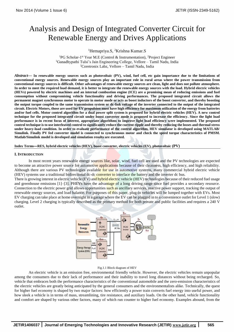
In most recent years renewable energy sources like, solar, wind, fuel cell are used and the PV technologies are expected
to become an attractive power source for automotive applications because of their cleanness, high efficiency, and high reliability.
Although there are various PV technologies available for use in automotive systems, many commercial hybrid electric vehicle
(HEV) systems use a traditional bidirectional dc-dc converter to interface the battery and the inverter dc bus.
There is growing interest in electric vehicle (EV) and hybrid electric vehicle (HEV) technologies because of their reduced fuel usage
and greenhouse emissions [1]–[3]. PHEVs have the advantage of a long driving range since fuel provides a secondary resource.
Connection to the electric power grid allows opportunities such as ancillary services, reactive power support, tracking the output of
renewable energy sources, and load balance. For purposes of this paper, plug-in vehicles will be lumped together with EVs. Most
EV charging can take place at home overnight in a garage where the EV can be plugged in to a convenience outlet for Level 1 (slow)
charging. Level 2 charging is typically described as the primary method for both private and public facilities and requires a 240 V
outlet.
Fig.1.1 Block diagram of HEV
An electric vehicle is an emission free, environmental friendly vehicle. However, the electric vehicles remain unpopular
among the consumers due to their lack of performance and their inability to travel long distances without being recharged. So,
vehicle that embraces both the performance characteristics of the conventional automobile and the zero-emission characteristics of
the electric vehicles are greatly being anticipated by the general consumers and the environmentalists alike. Technically, the quest
for higher fuel economy is shaped by two major factors: how efficiently a power train converts fuel energy into useful power, and
how sleek a vehicle is in terms of mass, streamlining, tire resistance, and auxiliary loads. On the other hand, vehicle functionality
and comfort are shaped by various other factors, many of which run counter to higher fuel economy. Examples abound, from the

Nov 2014 (Volume 1 Issue 6) JETIR (ISSN-2349-5162)
JETIR1406037 Journal of Emerging Technologies and Innovative Research (JETIR) www.jetir.org 566
way torque converter sacrifices efficiency to provide better shift smoothness and responsiveness to the wide variety of features that
add mass to a vehicle.
II. EV/HEV SYSTEM CONFIGURATIONS
The parallel hybrid electric vehicle (HEV) [1]–[3] and electric vehicle (EV) [4], [5] system as shown in Fig. 1, the converter
is used for boosting the battery voltage to rated dc bus for an inverter to drive motor. In the multi-motor drive system [6], [7], the
system will use two or more motors to boost torque, especially under low speed and high-torque region as shown in Fig. 2.2 (a).
For such applications, two or more inverters/converters are required. Fig. 2.2 (b) shows the application of the proposed integrated
circuit for motor drives with dual-mode control for EV/HEV applications. As shown in Fig. 3, the proposed integrated circuit allows
the permanent magnet synchronous motor (PMSM) to operate in motor mode or acts as boost inductors of the boost converter, and
thereby, boosting the output torque coupled to the same transmission system or dc-link voltage of an inverter connected to the
output of the integrated circuit. In motor mode, the proposed integrated circuit acts as an inverter and it becomes a boost-type boost
converter, while using the motor windings as the boost inductors to boost the converter output voltage. Therefore, the proposed
integrated circuit can significantly reduce the volume and weight of the system.
(a) (b) Fig. 2.1 HEV and EV system (a) Parallel HEV drive train. (b) EV drive train
The integrated circuit presented in this paper can act as an inverter and a boost
converter depends on the operation mode. For the integrated circuit, it not only can reduce the volume and weight but also boost
torque and dc-link voltage for motor/ converter modes, respectively. Moreover, a new control technique for the proposed integrated
circuit under boost converter mode is proposed to increase the efficiency.
(a)
(b)
Fig. 2.2 Multi-Motor drive system of EV/HEV (a) Conventional system, (b) Proposed
Integrated Converter System For conventional circuit, shown in Fig. 4(a) and (b), a single phase boost
converter [8] has been widely used for boost control due to its simplicity.
However, for higher power applications, an interleaved boost converter can
reduce the current ripple and components stress and thereby reducing the
losses and thermal stress. Based upon the interleaved control idea, a
boost-control technique using motor windings as boost inductors for the
proposed integrated circuit will be proposed. Under light load, the
integrated circuit acts as a single-phase boost converter for not invoking
additional switching and conduction losses, and functions as the two- phase
interleaved boost converter under heavy load to significantly reduce the
current ripple and thereby reducing the losses and thermal stress.
Therefore, the proposed control technique for the proposed integrated
circuit under boost converter mode can increase the efficiency.
III. INTEGRATED CIRCUIT AND CONTROL TECHNIQUE
Ba Co In El
Internal
Tran
Ba
Co In El
Ge
B C I E
C I E
GB In E
Pr E
G
Boost
Converter
Inverter
Mode
Boost
Mode

Nov 2014 (Volume 1 Issue 6) JETIR (ISSN-2349-5162)
JETIR1406037 Journal of Emerging Technologies and Innovative Research (JETIR) www.jetir.org 567
1. Integrated Inverter/Converter Circuit:
Fig.3.1 Integrated circuit for motor drives and boost converter The above fig. 3.1 shows the integrated circuit
for inverter and converter mode control. In this fig. 3.2
(a), Cin and Cout can stabilize the voltage when input and
output voltages are disturbed by source and load, respectively. Diode (D) is used for preventing output voltage impact on the input
side. When the integrated circuit is operated in inverter (motor) mode, relay will be turned ON and six power devices (IGBTs in
Fig. 3.1) are controlled by pulse width modulation (PWM) control signals.
When the proposed integrated circuit is operated in the converter mode, relay is turned OFF. And a single-phase or
interleaved control method will be applied to control of the power devices depending upon the load conditions. Figs. 6 and 7 show
the single-phase and two-phase interleaved boost converters. In Fig. 3.1, the single-phase boost converter uses power switch V*,
stator winding “A,” and winding “B” to boost the output voltage. In Fig. 3.1, two-phase interleaved boost converter uses power
switches V* and W*, stator winding “A,” winding “B,” and winding “C” to boost the output voltage and reduce the current ripple.
2. Modeling and Control for Boost Mode Operation:
(a)
(b) Fig. 3.2 Equivalent Circuit (a) Boost converter, (b) Small-signal circuit
This section will introduce the model of boost converter and derive the transfer function of the voltage controller. Fig. 3.2 (b) shows
the non-ideal equivalent circuit of the boost converter, it considers non-ideal condition of components: inductor winding resistance
RL, collector-emitter saturation voltage VCE, diode forward voltage drop VD, and equivalent series resistance of capacitor Resr.
Analysis of the boost converter by using the state-space averaging method [14], small-signal ac equivalent circuit can be derived,
as shown in Fig. 3.2 (b). By Fig. 3.2 (b), the transfer function of the voltage controller can be derived as shown in (3.1),
(3.1)
Fig. 3.3 Block diagram of voltage loop, using a proportional-integral (PI) controller for the
compensator
In this paper, the switching frequency is 20 kHz and voltage loop
bandwidth will be less than 2 kHz and the designed controller shown in (3.2). And the phase margin should be more than 45◦ to
enhance the noise immunity. For the designed controller shown in (3.3), proposed converter interfaced to PMSM machine through
inverter topology.
(3.2)
IV. SIMUALTION ANALYSIS AND RESUTLS
Nov 2014 (Volume 1 Issue 6) JETIR (ISSN-2349-5162)
JETIR1406037 Journal of Emerging Technologies and Innovative Research (JETIR) www.jetir.org 568
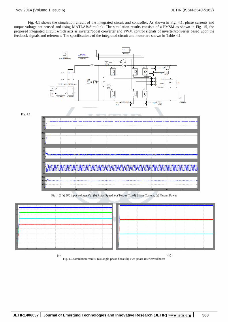
Fig. 4.1 shows the simulation circuit of the integrated circuit and controller. As shown in Fig. 4.1, phase currents and
output voltage are sensed and using MATLAB/Simulink. The simulation results consists of a PMSM as shown in Fig. 15, the
proposed integrated circuit which acts as inverter/boost converter and PWM control signals of inverter/converter based upon the
feedback signals and reference. The specifications of the integrated circuit and motor are shown in Table 4.1.
Fig. 4.1
Fig. 4.2 (a) DC input voltage Vdc, (b) Rotor Speed, (c) Torque Te, (d) Stator Current, (e) Output Power
(a) (b) Fig. 4.3 Simulation results: (a) Single-phase boost (b) Two-phase interleaved boost

Nov 2014 (Volume 1 Issue 6) JETIR (ISSN-2349-5162)
JETIR1406037 Journal of Emerging Technologies and Innovative Research (JETIR) www.jetir.org 569
(a) (b)
Fig. 4.4 Simulation results for the transition between single-phase control and two-phase interleaved control: (a) From single-phase to two-phase interleaved
modes. (b) From two-phase interleaved to single-phase modes
(a)
(b) Fig. 4.5 Measured current with and without interleaved control (a) Single-phase boost (b) Two-phase interleaved boost
As shown in Fig. 4.4, during the transition period, the output voltage is kept constant and the transition period is only 150 ms which
confirms fast dynamic response during mode transition. Fig. 4.5 shows the temperature of power devices in order to confirm the
reduction of switching losses contributed by the two-phase interleaved control method. When the proposed integrated circuit
operates in single-phase mode, the inductor current flows through the power device V* and its temperature will go up to 87.9 ◦C as
shown in Fig. 19(a). In contrast, when the proposed integrated circuit operates in two-phase interleaved mode, the inductor current
flows through the power devices V* and W* and their temperature will be 62 ◦C. This comparison result confirms the merit of the
control method for the integrated circuit under the boost-mode operation.
Similar results for other test conditions can be derived and will not be included in the paper due to length limitation. The measured
results for various power ratios and voltage ratios, under full-load condition, the maximum efficiency is more than 95% and
efficiency can be maintained at more than 91.7% for voltage ratios varies from 1.25 to 3, despite of different voltage ratios. These
results fully confirm the effectiveness of the proposed integrated circuit and control technique.
V. CONCLUSION
A new integrated inverter/converter circuit of motor drives with dual-mode control for EV/HEV applications to
significantly reduce the volume and weight; proposal of a new control method for the integrated inverter/ converter circuit operating
in boost converter mode to increase the efficiency; verification of the proposed integrated inverter/converter circuit; verification of
the proposed control method. Simulation results shows that the voltage boost ratio can go up to 3. Under full-load condition, the
maximum efficiency is more than 95% and efficiency can be maintained at more than 91.7% for voltage ratios varies from 1.25 to
3.
REFERENCES
[1] O. Hegazy, J. Van Mierlo, and P. Lataire, “Analysis, modeling, and implementation of a multidevice interleaved DC/DC
converter for fuel cell hybrid electric vehicles,” IEEE Trans. Power Electron., vol. 27, no. 11, pp. 4445–4458, Nov. 2012.
[2] W. Qian, H. Cha, F. Z. Peng, and L. M. Tolbert, “55-kW Variable 3X DCDC Converter for plug-in hybrid electric vehicles,”
IEEE Trans. Power Electron., vol. 27, no. 4, pp. 1668–1678, Apr. 2012.
[3] M. Yilmaz and P. T. Krein, “Review of battery charger topologies, charging power levels, and infrastructure for plug-in electric
and hybrid vehicles,” IEEE Trans. Power Electron., vol. 28, no. 5, pp. 2151–2169, May 2013.
[4] Y. S. Lai, C. A. Yeh, and K. M. Ho, “A family of predictive digital controlled PFC under boundary current mode control,”
IEEE Trans. Ind. Informatics, vol. 8, no. 3, pp. 448–458, Aug. 2012.
[5] Y. Jang, G. Feng, and M. M. Jovanovic, “Interleaved boost Converter with Intrinsic voltage-doubler characteristic for universal-
line PFC front end,” IEEE Trans. Power Electron., vol. 22, no. 4, pp. 1394–1401, July 2007.
[6] Y. Gu and D. Zhang, “Interleaved boost converter with ripple cancellation network,” IEEE Trans. Power Electron., vol. 28,
no. 8, pp. 3860–3869, Aug. 2013.

Nov 2014 (Volume 1 Issue 6) JETIR (ISSN-2349-5162)
JETIR1406037 Journal of Emerging Technologies and Innovative Research (JETIR) www.jetir.org 570
[7] Y. T. Chen, S. Shiu, and R. Liang, “Analysis and design of a zero-voltages witching and zero-current-switching interleaved
boost converter,” IEEE Trans. Power Electron., vol. 27, no. 1, pp. 161–173, Jan. 2012.
[8] R. W. Erickson and D. Maksimovi´c, Fundamental of Power Electronics, 2nd ed. Norwell, MA, USA: Kluwer, 2001.
AUTHOR’S PROFILE
S.HEMAPRIYA received B.E. degree from GANADHYPATHI TULSI’S JAIN ENGINEERING COLLEGE, Vellore – Tamil
Nadu, India in the year 2014 and currently pursing M.E. 1ST YEAR in CONTROL & INSTRUMENTATION at GANADHYPATHI
TULSI’S JAIN ENGINEERING COLLEGE, Vellore – Tamil Nadu, India. And her area of interests is Control System,
Instrumentation Control, Hybrid multilevel inverters.
S.KRISHNA KUMAR presently working as Project Engineer in Coretronix Labz, Vellore – Tamil Nadu. He did B.E. in Electrical
& Electronics Engineering in the year 2010 at PRIYADARSHINI ENGNEERING COLLEGE in Vaniyambadi and then completed
his M.E. in Electrical & Electronics Engineering as POWER ELECTRONICS AND DRIVES is specialization in the year 2012 at
SREE SASTHA INSTITUTE OF ENGINEERING & TECHNOLOGY, CHENNAI. He has an industrial experience of 2 years and
6 months. His area of interests is Micro grid applications, multilevel inverters, Hybrid Electric Vehicles.