an improved algorithm for variable slope differential ... · pdf filean improved algorithm for...
TRANSCRIPT
An Improved Algorithm for Variable Slope
Differential Protection of Distribution
Transformer using Harmonic Restraint
B S Shruthi
National Institute of Technology Karnataka, Surathkal, India
Email: [email protected]
K Panduranga Vittal
National Institute of Technology Karnataka, Surathkal, India
Email: [email protected]
Abstract—In the context of reliable protection of distribution
transformer, differential protection is considered to be the
best. The infiltration of Distributed Energy Resources into
the grid has necessitated the security of transformer to be
increased many fold. In this paper, an improved variable
slope differential method is proposed for a 1 MVA, 11/0.433
kV /Y connected distribution transformer considering
provision for accounting challenges of DES penetration. By
using second and fifth harmonic restraint, along with
negative sequence component, it is possible to effectively
differentiate between various conditions like inrush, over
excitation and internal fault including inter turn fault with
few shorted turns. Apart from these, cases for remanence
and external fault are also taken up to test the reliability of
the scheme. Effective simulation studies have been
performed to demonstrate the efficiency of the proposed
scheme using PSCAD/EMTDC.
Index Terms—differential protection, distributed generation,
Distribution transformer, harmonic restraint.
I. INTRODUCTION
Distribution transformers are generally considered to
be those which provide transformation from 11kV or
lower voltages down to the level of final distribution. The
main intention of transformer protection is to provide the
ability to detect internal faults with high sensitivity, along
with a high degree of immunity to operation on system
faults for which tripping of transformer terminal breaker
is not required. It is based on the fact that the differential
current will be high only in the case of faults internal to
the zone. Security of transformer differential protection
schemes is dependent on detecting the magnetizing inrush
currents of the protected transformer and associated
blocking of differential operation due to inrush related,
non-fault and other unbalance currents. Variable slope
differential protection is one of the schemes that provide
restraint against inrush and under overexcitation.
Manuscript received March 1, 2013; revised June 10, 2013.
With the connection of DG, the system loses radial
configuration. Since the DG sources also contribute to the
fault, the system coordination could be lost. M. Mañana
et. al. [1] concluded that magnetizing inrush currents of
power transformers have to be limited, especially when
they share a common bus with DG. With the proliferation
of DG installed at the customer load site, the delta-wye
distribution transformers become sources of fault current
that can be difficult to detect and isolate. Under worst-
case scenarios, without proper protection, the customer
generation may keep the faulted utility circuit energized
even after the utility source breakers have opened.
Several schemes to detect and isolate the transformer
under such condition are discussed in [2].
Current differential relaying is the most commonly
used type of protection for transformers of approximately
10 MVA three-phase and above. Although utility practice
for protection of distribution transformers as of now is
only through remote back up or fuses local to transformer,
it is envisaged in future with DG penetration that
differential protection becomes inevitable. General
protection issues with DG proliferation are gaining
importance [3]-[5] but its impact on distribution
transformer protection is not sought much. Detailed
analysis and publications are not available for reliable
transformer protection and hence the main objective of
this work is to address these concerns. Improvement of
the existing protection scheme is taken up as the first
phase and is the focus of this paper.
In the context of protection, transformer inrush is of
large importance and appropriate models for these
transient behaviors needs to be chosen. Unified magnetic
equivalent circuit (UMEC) model in PSCAD/EMTDC
has the ability to accurately reproduce the unbalance
operations. A 1 MVA, 11/0.433 kV /Y connected
transformer is opted for the purpose of this study. The
following section discusses the general differential
protection for a transformer along with the issues related
to the same followed by variable slope differential
protection. Section 3 briefs about the proposed relay logic.
61

Few simulation results to support the developed scheme
are presented in the last section.
II. TRANSFORMER DIFFERENTIAL PROTECTION
Transformer is one of the most important equipment in
power systems and it is important that adequate measures
are taken for protection. Differential protection is a fast,
selective method of protection against short circuits in
transformers. In a basic differential protection scheme,
currents on both sides of the transformer are compared.
Under normal conditions, primary and secondary currents
are equal and hence no difference current flows.
There has been renewed interest in devising a reliable
scheme for the protection of transformer using various
methods. B. Kasztenny et. al. [6] reviewed the principles
of protection against internal short circuits in
transformers of various constructions. A new approach
for transformer differential protection using current-only
inputs is described in [7]. Various protection schemes
with neural network algorithms and wave-shape
recognition techniques have also been proposed [8–11].
Sequence components have also been proved useful. H.
Khorashadi-Zadeh [12] describes the complete design of
a prototype digital protective relay for three-phase
transformers using positive sequence current whereas
usage of negative-sequence currents in order to both
detect and determine the position of the fault with respect
to the protected zone is dealt with in [13].
The nature of power transformers creates several
complications for the application of such differential
relays.
Magnetizing inrush currents created by
transformer transients
Phase shift between primary and secondary for
delta-wye connections
Variable ratio of the power transformer caused by
a tap changer
High exciting currents caused by transformer
overexcitation
Mismatch between the CT ratios and CT
Saturation
Differential relays are prone to maloperation due to
one or more of the above mentioned reasons. Harmonic
restraint or blocking methods ensure relay security for a
very high percentage of inrush and overexcitation cases.
The selection of CTs along with choice of percentage
slope for differential relaying and the effects of
magnetizing inrush are discussed in detail in [14].
A variable-percentage or dual-slope characteristic,
further increases relay security for heavy CT saturation.
Several common methods for defining restraint and slope
characteristics are examined and guidance on selection of
the correct slope setting is provided in [15].
Modern day transformers make use of IEDs designed
for protection, control, measurement and. Parameter
setting and DFR records can be accessed using the IEC
61850 protocol. Oscillographic files are available to any
Ethernet-based application in the standard COMTRADE
format. Flexible user settings afford programming for
different CT ratios and transformer phase shifts [16].
Digital relaying technique thus provides value addition to
the well-established percentage differential relays.
III. DEVELOPMENT OF RELAYING SCHEME
In transformer differential applications, CTs are
selected to accommodate a maximum fault current along
with preserving low current sensitivity. As a minimum
goal, CT saturation should be avoided for the maximum
symmetrical external fault current. The CT ratio and
burden capability should also permit operation of the
differential instantaneous element for the maximum
internal fault. Detailed procedure for selection of CT is
given in [17].
Inrush or overexcitation conditions of a power
transformer produce distorted currents because they are
related to transformer core saturation. The distorted
waveforms provide information that helps to discriminate
these conditions from internal faults. The restrained
differential is designed to sensitively clear internal faults
while remaining secure under other unbalance conditions.
Digital relays use unrestrained differential that
provides a very fast clearance of severe internal faults
with a high differential current regardless of their
harmonics. The second harmonic restraint, together with
the waveform based algorithms, ensures that the
restrained differential does not trip due to the transformer
inrush currents. The fifth harmonic restraint ensures that
the restrained differential does not trip on apparent
differential current caused by a harmless transformer
over-excitation [16].
Among the several research work that describe similar
relaying schemes, fault discriminants for differential
protection of transformer have been defined in [18] using
the information available from harmonic analysis. The
second and fifth harmonics along with transformer
primary voltage amplitude provides accurate distinction
between over excitation and internal fault condition. A
parabolic characteristic digital differential relay has been
developed based on the above discriminants.
But the traditional transformer differential percentage
protection is not sensitive enough to detect minor internal
winding faults. A short circuit of a few turns of the
winding will give rise to a heavy fault current in the
short-circuited turns, but changes in the transformer
terminal currents will be very small, because of the high
ratio of transformation between the whole winding and
the short-circuited turns.
Addition of DG sources might cause significant effects
to the existing scheme. Issues like sympathetic inrush
could add to problems such as increase in fault current
due to the additional source and directionality of flow.
This calls for certain improvements in the conventional
relay logic, including the capability to detect internal
winding faults.
Instantaneous differential and bias currents are
calculated from the CT outputs and harmonic analysis is
carried out. The fundamental, second and fifth harmonic
of the differential current is extracted along with its
62
negative sequence component and the fundamentals of
restraining current and the primary voltage.
The threshold values for each of these are chosen
based on the simulation results. For severe internal faults,
unrestrained operation is desired. If the fundamental
harmonic of differential current is higher than a set value,
and second harmonic component is below a threshold,
immediate trip decision is given. Parabolic characteristics
are used in other cases and trip signal is issued when
where Id1 and Ir1 are the fundamental components of
differential and restraining currents.
The values of a and b in this case are 0.3 and 0.08
respectively. Fault discriminant K is used to give a stable
discrimination between inrush and internal fault condition.
If K and Id2 are greater than their threshold values,
inrush indicator flag is set. To check for overexcitation
condition, verify whether the voltage level is greater than
times normal voltage (say =1.1), and also whether
fifth harmonic component, Id5 has increased. Finally if the
voltage at primary terminals has collapsed below times
normal voltage (say = 0.9), and the negative sequence
component is higher than a set threshold, increment the
trip counter for inter-turn fault. In any case the trip
counter is incremented up to 3 before giving the trip
decision. This approach ensures security under external
faults, inrush and overexcitation, and dependability for
internal faults along with maintaining sensitivity.
There can be several ways to use the harmonic restraint
scheme. The approach generally in practice is to consider
the second and the fifth harmonic as a percentage of
fundamental. The restraint can be applied by considering
each phase separately or all the three phases together. In
case of choosing a common restraint, considering the sum
of harmonics of each of the three phases gives an
additional advantage of setting a higher value of restraint
compared to averaging over the three phases. Adaption of
the appropriate technique depends on the application.
IV. SIMULATION RESULTS
The performance is evaluated through extensive
simulations using the PSCAD/EMTDC software. Few
typical results obtained are given in this section. A 1
MVA, 11/0.433 kV common core, three limb transformer
was taken up for study, the primary being connected in
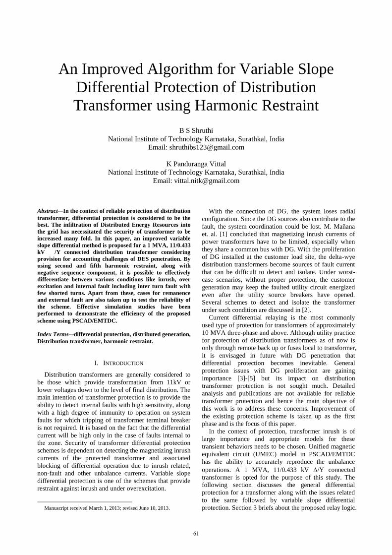
delta and secondary in star. The system simulated is as
shown in the figure 1 below.
Figure 1. PSCAD model used for simulation.
Harmonic analysis of the differential current leads us
to the result shown below. Table I shows the maximum
value of various harmonic components as a percentage of
fundamental under inrush and internal fault condition. It
can be seen that second harmonic is highly predominant
in the case of inrush.
Armando Guzmán et. al. [19] summarize the existing
methods for discriminating internal faults from inrush and
overexcitation conditions along with comparative studies
between harmonic restraint and blocking methods.
Following are the various cases that were analyzed to
check the dependability of the above mentioned
protection scheme.
TABLE I. DIFFERENTIAL CURRENT AS A PERCENTAGE OF
FUNDAMENTAL
Harmonic Differential Current Component (%)
Inrush Internal Fault
Fundamental 100 100
Second 46.64 28.92
Third 21.22 16.64
Fourth 17.37 10.89
Fifth 14.52 8.58
Sixth 16.85 8.53
Seventh 18.64 10.98
A. Magnetizing Inrush
During transformer energization, the inrush current can
be as high as 8 – 30 times the rated current for few cycles,
depending upon the transformer core and system
resistance. Other factors that affect the inrush current are
the point on voltage waveform during switching and
residual flux in core.
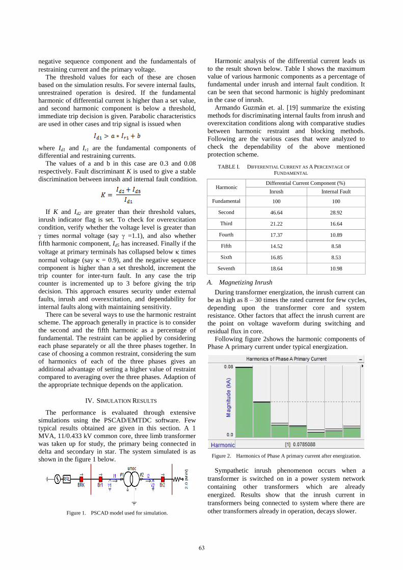
Following figure 2shows the harmonic components of
Phase A primary current under typical energization.
Figure 2. Harmonics of Phase A primary current after energization.
Sympathetic inrush phenomenon occurs when a
transformer is switched on in a power system network
containing other transformers which are already
energized. Results show that the inrush current in
transformers being connected to system where there are
other transformers already in operation, decays slower.
63

B. Remanent Flux In Core
When a transformer is de-energized, the magnetizing
voltage is taken away, the magnetizing current goes to
zero while the flux follows the hysteresis loop of the core.
This results in a residual flux in the core. Remanence may
be as high as 80-90% of the rated flux, resulting in large
peak values and heavy distortions of magnetizing current.
Simulations were carried out with various amounts of
remanent flux in core. The Fundamental and Second
harmonic extracted from FFT analysis with a remanence
of -60% in phase A, 50% and -20% in phase B and C
respectively is as shown in the figure 3 below. Figure 4
shows the inrush flag set after energization.
Figure 3. Fundamental and 2nd harmonic under remanence condition.
Figure 4. Inrush flag with remanent flux.
C. Internal Fault
The internal electrical faults that can occur are winding
short circuits, winding to ground or turn to turn faults.
Various types of temporary and permanent faults were
simulated on both the windings of the transformer. It was
observed that in every case, the trip signal was issued at
around 20ms from the time of fault inception.
As an example, a temporary phase A to C to ground
fault on the primary winding of the transformer is
considered. Fault is applied from 0.2 sec to 0.3 sec.
Figure 5. Differential and restraining current under ACG fault.
Figure 5 shows fundamental of differential current
rising to an extremely high value and quick trip decision
should be given before the flow of this high current
causes damage to the winding or insulation. The trip
decision is given at 0.221 sec, which is considerably good
from the transformer safety point of concern.
Figure 6. Inrush and trip signal under ACG fault.
Turn to ground and turn to turn faults were simulated
by creating new components with the help of FORTRAN
programming. The change in inductance matrix under
fault was derived using the basic equations based on
consistency, leakage and proportionality. Satisfactory
results were obtained for various levels of shorted turns
which justify the necessity of using negative sequence
component as an additional discriminant.
D. External Fault
From the point of view of differential protection, it is
also important to study the effects of out of zone faults. In
some cases, there might be unusual maloperation of the
differential protection after removal of external fault. The
reason is that saturation states of CTs on either side are
different after an external fault occurs [20].
An example of phase A to C double line fault on the
secondary side considered. The main difference is that
restraining current becomes higher than the differential
current which is seen in figure 7. Inrush and trip indicator
is as seen in figure 8.
Figure 7. Differential and restraining current under AC fault.
Figure 8. Inrush flag under AC external fault.
64

E. Over Excitation
The magnetic flux inside the transformer core is directly proportional to the applied voltage and inversely proportional to the system frequency. Overvoltage and/or under frequency conditions can produce flux levels that saturate the transformer core.
Over excitation condition was simulated by increasing
the voltage in steps. It was observed that for every step
increase in voltage, a new level of inrush current is
reached and it also causes a rise in the fifth harmonic.
Figure 9. 5th harmonic during overexcitation.
Figure 10 shows the inrush and over excitation flag.
Though the transformer core saturated, the relay was
found to be stable even up to 150% of rated voltage.
Figure 10. Inrush and overexcitation flag.
V. CONCLUSION
Internal electrical faults in transformers are very
serious and cause immediate damage. Short circuits and
ground faults in windings and terminals are normally
detected by variable slope differential protection. Second
and fifth harmonic restraint provides discrimination
against inrush and overexcitation condition. Under inter
turn fault, lesser the number of turns shorted, lesser will
be the current and hence detection through harmonic
analysis is not always feasible. Under such situations
negative sequence restraint provides better sensitivity. A
relay logic combining all these along with voltage
restraint is proposed in this paper. Simulation results have
proved that the relay gives acceptable decisions under
various operating and fault conditions of the transformer.
Addition of DER to a distribution or sub-transmission
system has the potential to impact relay systems well
beyond the point of common coupling. Distribution
systems are basically designed as radial networks and
revision of the existing protection schemes become
necessary with DG integration. Different DG sources
show different characteristics towards their ability to
provide short circuit current needed to trip the relay.
Distribution transformers, in particular face problems like
inrush, ferroresonance, etc. along with CT saturation.
Sympathetic inrush phenomenon also becomes more
evident and sensitivity of the relays becomes important.
Hence the work carried out here will aid in taking
adequate measures for distribution transformer protection
in networks where there is flow of negative sequence
current and intermittency.
REFERENCES
[1] M. Mañana, L.I. Eguíluz, A. Ortiz, G. Díez, C.J. Renedo, and S.
Pérez, “Effects of Magnetizing Inrush Current on Power Quality
and Distributed Generation,” IX Spanish Portugese Congress on Electrical Engineering, Marbella, July 2005.
[2] K. Behrendt, “Protection for Unexpected Delta Sources,”
Schweitzer Engineering. Laboratories, Inc., Oct 2002.
[3] M.Paz Comech, Miguel Garcia-Gracia, Samuel Borroy, and
M.Teresa Villen, “Protection in distribution generation,” CIRCE,
Feb 2010, pp. 289-310. [4] J.A. Martinez and J. Martin-Arnedo, "Impact of distributed
generation on distribution protection and power quality," IEEE
Power Engineering Society General Meeting, July 2009. [5] H. Zayandehroodi, A. Mohamed, H. Shareef, and M.
Mohammadjafari, “A Comprehensive review of protection coordination methods in power distribution systems in the
presence of DG,” Przegląd Elektrotechniczny, Vol. 87, No. 8, Aug
2011, pp. 142-148. [6] B. Kasztenny, M. Thompson, and N. Fischer, “Fundamentals of
Short-Circuit Protection for Transformers,” Proc. of 63rd Annual
Conference for Protective Relay Engineers, College Station, TX, March 2010.
[7] A. Guzmán, S. E. Zocholl, G. Benmouyal, and H. J. Altuve,
“Performance Analysis of Traditional and Improved Transformer Differential Protective Relays,” presented at the Minnesota Power
Systems Conference, Minneapolis, Minnesota, Nov 7-9, 2000.
[8] M. Tripathy, “Power Transformer Differential Protection Based on Neural Network Principal Component Analysis, Harmonic
Restraint and Park’s Plots,” Research article published in
Advances in Artificial Intelligence, Volume 2012, Jan 2010. [9] A. Guzmán, S. Zocholl, G. Benmouyal and Héctor J. Altuve, “A
Current-Based Solution for Transformer Differential Protection—
Part II: Relay Description and Evaluation,” IEEE Transactions on Power Delivery, Vol. 17, No. 4, Oct 2002, pp. 886-893.
[10] H. Khorashadi-Zadeh, “Power Transformer Differential Protection
Scheme Based on Symmetrical Component and Artificial Neural Network”, 7th Seminar on Neural Network Applications in
Electrical Engineering, IEEE Sep 23-25, 2004.
[11] H. Khorashadi-Zadeh, M. Sanaye-Pasand, “Power transformer differential protection scheme based on wavelet transform and
artificial neural network algorithms,” Proc. of the 39nd
International Universities Power Engineering Conference, 2004, pp. 747-753.
[12] H. Khorashadi-Zadeh, “Transformer Differential Protection Using
Positive Sequence Current; Design and Implementation,” Power Tech, IEEE Russia, 27-30 June 2005, pp. 1-5.
[13] I. Brncic, Z. Gajic, and T. Einarsson, “Transformer Differential
Protection Improved by Implementation of Negative-Sequence Currents,”ABB Power Technologies, Sweden, 2006.
[14] Russell C. Mason. "The Art and Science of Protective Relaying,"
General Electric, John Wiley & Sons, Jan 1956, ch. 11, pp. 211-239.
[15] M. J. Thompson, “Percentage restrained differential, percentage of
what?”, 64th Annual Conference for Protective Relay Engineers, April 2011, pp. 278-289.
[16] 615 series ANSI technical manual, ABB, July 2011.
[17] S. E. Zocholl, A. Guzmán, D. Hou, “Transformer Modeling as Applied to Differential Protection,” 22nd Annual Western
Protective Relay Conference, Spokane, WA, Oct 24-26, 1995.
[18] K. P. Vittal, “Numeric Protection Relays and Development
of Microcontroller based Hardware and cascaded Bandpass
Structures for Power System Relaying Schemes,” Doctoral
dissertion, KREC, Surathkal, May 1998. [19] A. Guzmán, S. Zocholl, G. Benmouyal and Héctor J. Altuve, “A
Current-Based Solution for Transformer Differential Protection—
65
Part I: Problem Statement,” IEEE Transactions on Power Delivery, Vol. 16, No. 4, Oct 2001, pp. 485-491.
[20] X. Lin, H. Weng, P. Liu, B. Wang, and Z. Bo, “Analysis of a Sort
of Unusual Mal-Operation of Transformer Differential Protection Due to Removal of External Fault,” IEEE Transactions on Power
Delivery, Vol. 23, No. 3, July 2008, pp. 1374-1379.
B S Shruthi was born in Bangalore, in 1989. She
received her Bachelor of Engineering degree in
Electrical and Electronics Engineering from The National Institute of Engineering, Mysore in 2011.
She is currently perusing M.Tech by Research in the
field of Power and Energy Systems at The National Institute of Technology Karnataka (NITK). Area of
Research is Development of Integrated Protection
Schemes for Protection of Transformers Supporting Deregulated Distribution Systems.
She is a Student Member of IEEE along with IEEE – Power
Engineering Society and IEEE – Women in Engineering. Her areas of interest include Power System Protection, Power Transformers,
Distributed Generation and Embedded Systems.
Dr. Panduranga Vittal K was born in Bellary, in 1964. He received his B.E. (E & E) degree from
Mysore University in the year 1985, M.E. (Applied
Electronics) degree in 1989 from PSG College of technology, Coimbatore. Then he earned Ph D.
degree from NITK during the year 1999. Presently,
Dr.Vittal is serving as Professor and Head of Dept. of Electrical & Electronics Engineering, National Inst.
of Technology, Karnataka – Surathkal, Mangalore.
He is a senior member of IEEE, Member of IEEE-Power Engineering Society, Life member of ISTE and IE (India). He has
published 50 technical research papers in various National and
International conferences and 15 papers in International Journals. He has chaired several international conferences in India and abroad.
Recently he has served as chairman for IEEE, ICIIS-2010 an
international conference and NSC-2010 a national conference. He has been principal investigator in various funded projects from Indian
government and University programs of industries. He has guided and
also presently guiding several research scholars for the award Ph.D. degree.
His research areas of interest include power system protection,
power quality and design of embedded systems.
66