improved transformer differential protection by adaptive
TRANSCRIPT

POWER ENGINEERING AND ELECTRICAL ENGINEERING VOLUME: 18 | NUMBER: 3 | 2020 | SEPTEMBER
Improved Transformer Differential Protection byAdaptive Pickup Setting during Momentary
Over-Fluxing Condition
Maulik RAICHURA1, Nilesh CHOTHANI 2, Dharmesh PATEL 3
1Electrical Department, Gujarat Technological University,GJ SH 41, Near Visat Three Roads, Nigam Nagar, Chandkheda, 382 424 Ahmedabad, India
2Electrical Department, Adani Institute of Infrastructure Engineering, Gujarat Technological University,Nr Vaishnodevi Circle, SG Highway, 382 421 Ahmedabad, India
3Electrical Engineering Department, Government Engineering College,Old National Highway-8, 392 002 Bharuch, India
[email protected], [email protected], [email protected]
DOI: 10.15598/aeee.v18i3.3833
Abstract. The differential relaying scheme is univer-sally adopted as the main protection for power trans-former. In certain situations, like temporary over-fluxing, this differential protection may malfunction.This is due to unbalance in primary and secondarycurrent, as the saturated core does not reflect equalampere-turn on either side. This article presents detec-tion of over-fluxing condition against the internal faultbased on the fifth harmonic component of differentialcurrent. As per the estimated level of the fifth harmonicconcerning the fundamental component of differentialcurrent, the pickup setting of percentage bias character-istic will be modified to avoid maloperation. Once theover-flux condition is sensed, the algorithm activatestimer-based V/f protection to protect the equipment.The proposed algorithm is validated on PSCAD™ soft-ware and after the collection of data, MATLAB soft-ware is used for further validation. The proposed al-gorithm is validated under various test conditions likenormal load, external fault, internal fault, and over-fluxing. It is observed that the algorithm accurately de-tects internal fault in the transformer or blocks the re-lay operation under momentary over-fluxing situations.Further, to assassinate the competency of the proposedscheme, a practical test is performed on a single-phasetransformer available in laboratory. The data for var-ious test cases are captured with the help of DSO, andthe collected data has been migrated to computer wherethe proposed algorithm is examined. After analyzingall the results, it is cleared that the proposed algorithmcan prevent transformer isolation during momentaryover-fluxing conditions.
Keywords
Differential relay, fault, harmonic components,MDFT, over-fluxing, power transformer.
1. Introduction
A transformer is a very imperative part of the powersystem. A nonlinear inherent property of the coremay cause over-flux or over-excitation situations in thetransformer. Moreover, a change in V/f ratio of thetransformer and subsequent over-flux condition arisesfrom various phenomena like sudden load cut off, gen-erator running on low frequency due to inadequatemechanical power, tripping of a heavily loaded trans-mission line, improper shunt compensation etc. Thereare some dedicated protections available like V/f relaypreventing the transformer from the hazardous effectsposed due to the above-mentioned situations. However,the severity of over-fluxing condition may breach thebalance between primary and secondary side currentsof the transformer, and false operation of the differ-ential protection scheme may result. So, it is indeeda proactive need to provide adaptive pickup charac-teristics under the momentary over-fluxing situationto avoid malfunctioning of the differential protectivescheme.
The setting of over-fluxing relay (V/f) is normallyadjusted to 1.1 to 1.3 per unit [1] with adjustable timedelay under temporary disturbance. Despite havingthis protective measure, the raise of imbalance between
© 2020 ADVANCES IN ELECTRICAL AND ELECTRONIC ENGINEERING 180

POWER ENGINEERING AND ELECTRICAL ENGINEERING VOLUME: 18 | NUMBER: 3 | 2020 | SEPTEMBER
primary and secondary side currents may activate thedifferential protection relay. Furthermore, some inter-harmonics and voltage notching are generated in thesystem when sensitive loads are removed from the ter-minal end of the transformer. The electrical isolationof the transformer is also not able to remove these volt-ages [2]. Xiangning Lin et al. mentioned in their book[3] on page 3 that the V/f protection scheme will is-sue trip signal if this ratio (V/f) exceeds 1.1 per unit.They have specified that these types of situations ariseslowly, and it is considered as one type of incipientfault. Also, they have stated that if the over-flux is de-tected, transformer should be isolated. However, if thecondition is momentary, then immediate tripping is anundesired condition. IEEE standard allows over-fluxsituation up to 1.25 per unit [4].
With the help of flux locus [5], transformer magnetiz-ing condition is well defined. Increment of flux in powertransformer is also one of the most effective parametersthat are utilized to detect winding and faulted phase[6]. The bright side of flux related algorithm is thatit does not require hysteresis data and analysis dueto time-domain operating conditions. With the helpof core magnetic flux characteristics [7], power trans-former protection is also suggested as an improved con-ventional protective scheme. Ratio of flux linkages inboth primary and secondary sides of the core is also animportant parameter for the transformer protection.Using comparative analysis like ratio of the flux link-ages, an algorithm is proposed for transformer protec-tion [8]. Similarly, fluxional current is also an impor-tant function to provide protection [9]. Even all inone unique protective scheme for transformer is sug-gested in research article [10] including CT saturation,over-voltage and over-fluxing conditions to avoid mal-operation with stability consideration. However, suchscheme also falsely operates during flux-based protec-tion because of a lack of preventive measures.
Then, over-current and over-fluxing conditions havebeen addressed by transformer numerical Inverse Def-inite Minimum Time (IDMT) based relaying schemein [11]. Although the IDMT-based relay prevents falseoperation against immediate tripping during over-fluxcondition, it will delay main protection. A novel al-gorithm with ultra-saturation detection of transformerhas been proposed by Bahram Noshad in [12]. In thisarticle, the algorithm only detects ultra-saturation con-dition of the transformer with the help of DiscreteWavelet Transform (DWT), and makes the relay re-strained. However, consequences during extra high sat-uration phenomena and during persistence of the ultra-saturation for a long time were not clarified. NehaBhatt et al. [13] presented causes and effects of over-fluxing in transformers and compared various tech-niques for its detection. Estimation of current in a sat-urated transformer has been proposed in [14]. Here,
authors have used extended Kalman filter and Gauss-Newton method for estimation of current. However,they have used various assumptions in their proposedwork which is not always possible to presume.
Harmonics are capable of discriminating inrush andfault conditions with proper analysis of harmonic in-terference [15]. Inrush detection technique based onthe second harmonic content is compared with vari-ous techniques like cross blocking technique, averagepercentage blocking process, harmonic sharing system,and shows its effectiveness for inrush discrimination[16]. Harmonics are also generated during geomagneticdisturbance and based on that, transformer monitor-ing and its analysis can take place [17]. Abbas Ketabiet al. [18] have analyzed impact of various factors ontransformer switching overvoltages. They have also an-alyzed the duration of overvoltages during various situ-ations. Harmonic blocking and restraint techniques fortransformer differential protection have been proposedin [19].
Self-adaptive transformer differential protectionscheme is elaborated in [20], with slope shifting abil-ity of percentage bias characteristics. However, over-fluxing criteria remain untouched in protective frame-work. Even, most of the researchers proposed theirwork on V/f based technique [21] to tackle over-fluxing condition. Maheshwari et al. [22] stated over-excitation condition detection with the help of the fifthharmonic-based technique in their work. However, inthe proposed algorithm, only the relay restraint featurewas mentioned, and if the internal fault exists duringthat time, then the suggested scheme cannot detect it.
In this article, adaptive basic pickup setting of per-centage bias differential relay is proposed to preventmaloperation of the transformer protective scheme dur-ing momentary over-fluxing conditions with the helpof the fifth harmonic component of differential current.This technique introduces less complexity and mini-mizes a calculative burden with a higher proactive im-pact. The proposed technique is competent enough toprevent immediate differential tripping during the mo-mentary over-fluxing conditions. Moreover, V/f pro-tection is activated simultaneously to tackle the trans-former in continuous over-fluxing situation without af-fecting the operation of the differential relay. It is op-erated simultaneously with percentage bias differentialprotection after detection of over-fluxing condition.
The article is structured as follows. Section 1.briefs general information and work carried out by re-searchers. Section 2. describes the system diagramand related details. Section 3. explains the pro-posed technique with the formulation. Section 4.demonstrates result validation and its analysis. Last,a practical test on hardware prototype with results isbriefed in Sec. 5.
© 2020 ADVANCES IN ELECTRICAL AND ELECTRONIC ENGINEERING 181
POWER ENGINEERING AND ELECTRICAL ENGINEERING VOLUME: 18 | NUMBER: 3 | 2020 | SEPTEMBER
F Ph
RL
RL
RL
RL
R
A
A
B
BC
C
50.0
0.0
FAULTS
Vp
la1p
a
b
a
bf
a
b
f
lb1p
lc1p
Timed FaultLogic
A
B
C
f
A G
Vp
c
d
d
c
RL
RL
RLC
CB
BA
ARR
RLlb2s
c
d
lc2s
la2s
BRK
P+jQ
TLine3T
TLine2T
TLine1T
C
B
A
RRL
RL
A
B
C
V F Ph
RL RL
TimedBreaker
LogicClosed@t0
R
BRK
TimedBreake
LogicOpen@t
BRK
FAULTSC
B
A
A->G
TimedFaultLogic
P+
C
B
A
RRRL
RL
A
B
C
RL
TimedBreakerLogic
Closed@t
0.0
50.0
Vp
Vp
TLine1T
TLine2T
TLine3T
Ia1p
Ib1p
Ic1p
Ia2s
Ib2s
Ic2s
a
b
c
df
a
b
c
df
a
b
c
df
3-Phase Power Transformer100 MVA, 400/220 kV
Main: Controls
500
440
kV
500
400 kV voltage
+
+
-
TimedBreakerLogic
Closed @ t0
R3-Phase Power Transformer
100 MVA, 400/220 kVTimed
BreakerLogic
Closed @ t0
TimedBreakerLogic
Open @ t0
BRK
RRV
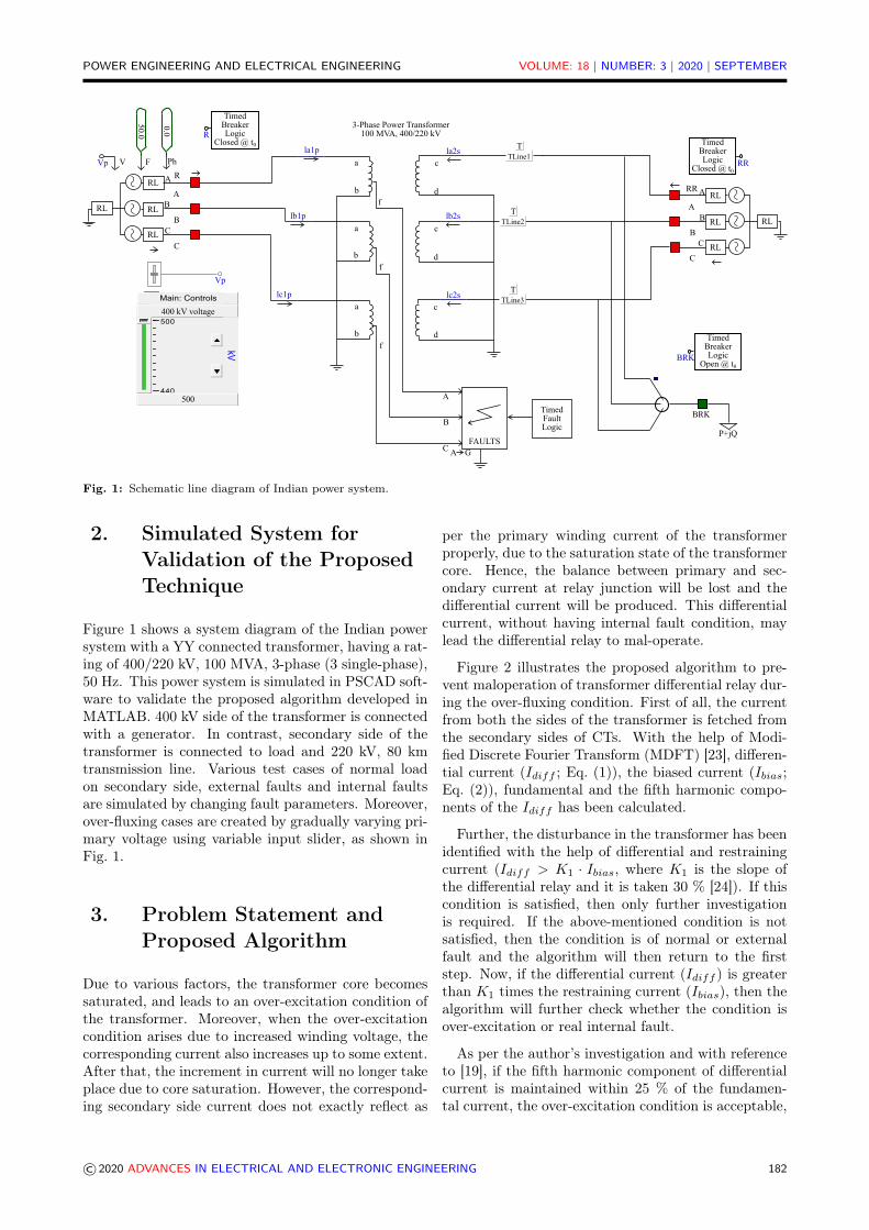
Fig. 1: Schematic line diagram of Indian power system.
2. Simulated System forValidation of the ProposedTechnique
Figure 1 shows a system diagram of the Indian powersystem with a YY connected transformer, having a rat-ing of 400/220 kV, 100 MVA, 3-phase (3 single-phase),50 Hz. This power system is simulated in PSCAD soft-ware to validate the proposed algorithm developed inMATLAB. 400 kV side of the transformer is connectedwith a generator. In contrast, secondary side of thetransformer is connected to load and 220 kV, 80 kmtransmission line. Various test cases of normal loadon secondary side, external faults and internal faultsare simulated by changing fault parameters. Moreover,over-fluxing cases are created by gradually varying pri-mary voltage using variable input slider, as shown inFig. 1.
3. Problem Statement andProposed Algorithm
Due to various factors, the transformer core becomessaturated, and leads to an over-excitation condition ofthe transformer. Moreover, when the over-excitationcondition arises due to increased winding voltage, thecorresponding current also increases up to some extent.After that, the increment in current will no longer takeplace due to core saturation. However, the correspond-ing secondary side current does not exactly reflect as
per the primary winding current of the transformerproperly, due to the saturation state of the transformercore. Hence, the balance between primary and sec-ondary current at relay junction will be lost and thedifferential current will be produced. This differentialcurrent, without having internal fault condition, maylead the differential relay to mal-operate.
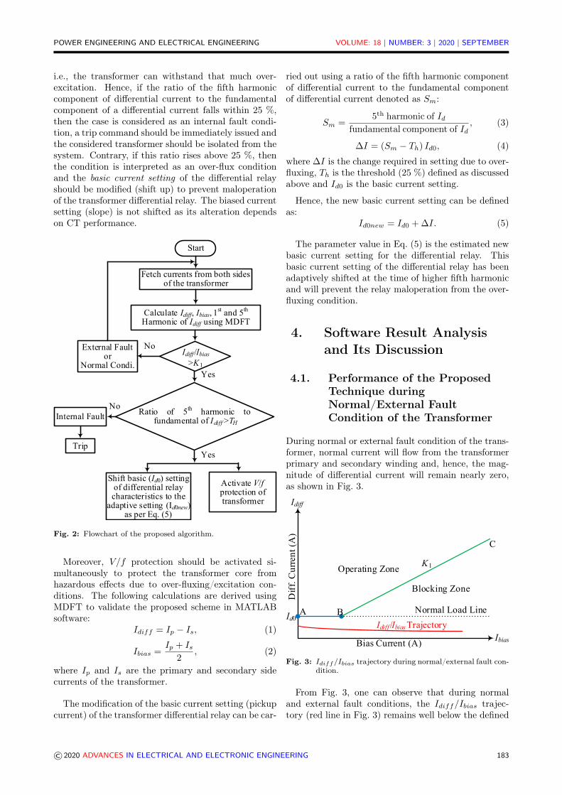
Figure 2 illustrates the proposed algorithm to pre-vent maloperation of transformer differential relay dur-ing the over-fluxing condition. First of all, the currentfrom both the sides of the transformer is fetched fromthe secondary sides of CTs. With the help of Modi-fied Discrete Fourier Transform (MDFT) [23], differen-tial current (Idiff ; Eq. (1)), the biased current (Ibias;Eq. (2)), fundamental and the fifth harmonic compo-nents of the Idiff has been calculated.
Further, the disturbance in the transformer has beenidentified with the help of differential and restrainingcurrent (Idiff > K1 · Ibias, where K1 is the slope ofthe differential relay and it is taken 30 % [24]). If thiscondition is satisfied, then only further investigationis required. If the above-mentioned condition is notsatisfied, then the condition is of normal or externalfault and the algorithm will then return to the firststep. Now, if the differential current (Idiff ) is greaterthan K1 times the restraining current (Ibias), then thealgorithm will further check whether the condition isover-excitation or real internal fault.
As per the author’s investigation and with referenceto [19], if the fifth harmonic component of differentialcurrent is maintained within 25 % of the fundamen-tal current, the over-excitation condition is acceptable,
© 2020 ADVANCES IN ELECTRICAL AND ELECTRONIC ENGINEERING 182
POWER ENGINEERING AND ELECTRICAL ENGINEERING VOLUME: 18 | NUMBER: 3 | 2020 | SEPTEMBER
i.e., the transformer can withstand that much over-excitation. Hence, if the ratio of the fifth harmoniccomponent of differential current to the fundamentalcomponent of a differential current falls within 25 %,then the case is considered as an internal fault condi-tion, a trip command should be immediately issued andthe considered transformer should be isolated from thesystem. Contrary, if this ratio rises above 25 %, thenthe condition is interpreted as an over-flux conditionand the basic current setting of the differential relayshould be modified (shift up) to prevent maloperationof the transformer differential relay. The biased currentsetting (slope) is not shifted as its alteration dependson CT performance.
Idiff /Ibias>K1
Ratio of 5th harmonic to fundamental of Idiff >TH
Calculate Idiff, Ibias, 1st and 5th
Harmonic of Idiff using MDFT
External Fault or
Normal Condi.
Internal Fault
Fetch currents from both sides of the transformer
Activate V/fprotection of transformer
Shift basic (Id0) setting of differential relay characteristics to the
adaptive setting (Id0new) as per Eq. (5)
No
Yes
Start
No
YesTrip
Fig. 2: Flowchart of the proposed algorithm.
Moreover, V/f protection should be activated si-multaneously to protect the transformer core fromhazardous effects due to over-fluxing/excitation con-ditions. The following calculations are derived usingMDFT to validate the proposed scheme in MATLABsoftware:
Idiff = Ip − Is, (1)
Ibias =Ip + Is
2, (2)
where Ip and Is are the primary and secondary sidecurrents of the transformer.
The modification of the basic current setting (pickupcurrent) of the transformer differential relay can be car-
ried out using a ratio of the fifth harmonic componentof differential current to the fundamental componentof differential current denoted as Sm:
Sm =5th harmonic of Id
fundamental component of Id, (3)
∆I = (Sm − Th) Id0, (4)
where ∆I is the change required in setting due to over-fluxing, Th is the threshold (25 %) defined as discussedabove and Id0 is the basic current setting.
Hence, the new basic current setting can be definedas:
Id0new = Id0 + ∆I. (5)
The parameter value in Eq. (5) is the estimated newbasic current setting for the differential relay. Thisbasic current setting of the differential relay has beenadaptively shifted at the time of higher fifth harmonicand will prevent the relay maloperation from the over-fluxing condition.
4. Software Result Analysisand Its Discussion
4.1. Performance of the ProposedTechnique duringNormal/External FaultCondition of the Transformer
During normal or external fault condition of the trans-former, normal current will flow from the transformerprimary and secondary winding and, hence, the mag-nitude of differential current will remain nearly zero,as shown in Fig. 3.
Normal Load Line
Bias Current (A)Ibias
Blocking Zone
Operating Zone
Dif
f. C
urre
nt (
A)
Idiff
Id0A B
C
K1
Idiff /Ibias Trajectory
Fig. 3: Idiff/Ibias trajectory during normal/external fault con-dition.
From Fig. 3, one can observe that during normaland external fault conditions, the Idiff/Ibias trajec-tory (red line in Fig. 3) remains well below the defined
© 2020 ADVANCES IN ELECTRICAL AND ELECTRONIC ENGINEERING 183

POWER ENGINEERING AND ELECTRICAL ENGINEERING VOLUME: 18 | NUMBER: 3 | 2020 | SEPTEMBER
Time (s)0.15 0.2 0.25 0.3 0.35
Cu
rren
t (A
)
-10
-5
0
5
10 Primary Current Secondary Current
Fig. 4: Transformer primary and secondary side current (CTsecondary) waveforms during normal condition (up to0.2 s) and external fault condition (0.2 s to 0.35 s) withdecaying DC component of fault current.
operating boundary, i.e. Id0 and slope K1 which isthe desired condition of a protection system. Hence,further attention is not required in this case.
Figure 4 shows primary and secondary side currentwaveforms on CT secondary of the considered trans-former. The External fault is initiated at 0.2 s, ascan be seen from Fig. 4 where the magnitude of bothprimary and secondary side current increases after in-ception of external fault condition. However, the risein magnitude of primary and secondary side currents isequal and opposite which will cancel out rising impactof each other and resultant differential current will re-main the same (i.e. ≈ 0). Hence, during external faultor normal condition, the transformer protective schemeremains inoperative.
4.2. Performance of the ProposedTechnique during Internal FaultCondition of the Transformer
From Fig. 5, it can be noted that during internal faultcondition, the Idiff/Ibias trajectory (red line of Fig. 5)immediately crosses the defined blocking limits and en-ter into the operating region. This will activate thedifferential relay to trip the circuit breakers. Althoughthis is the desired condition for the protection engineeras per the algorithm (Fig. 2) of the proposed technique,the condition of the over-flux will be checked as per theEq. (3). Further, if the over-flux is less than the definedthreshold (25 %), then only the relay will decide it asan internal fault condition and successfully issue a tripsignal. On the other hand, if the estimation of over-flux as per Eq. (3) exceeds the predefined threshold, itwill activate the V/f protection of the transformer andsimultaneously will prevent differential relay maloper-ation by shifting the basic setting of the characteristicwhich is further elaborated in subsequent section.
Normal Load Line
Bias Current (A)Ibias
Blocking Zone
Operating Zone
Dif
f. C
urre
nt (
A)
Idiff
Id0A B
C
K1
I diff
/I bias
Fig. 5: Idiff/Ibias trajectory during internal fault condition.
Time (s)0.15 0.2 0.25 0.3 0.35
Cu
rren
t (A
)
-5
0
5
10 Primary Current Secondary Current
Fig. 6: Primary and secondary side current waveforms duringinternal fault condition of the transformer.
4.3. Performance of the ProposedTechnique during Over-FluxingCondition of the Transformer
Normal Load Line
Bias Current (A)Ibias
Blocking Zone
Operating Zone
Dif
f. C
urre
nt (
A)
Idiff
Id0A B
C
K1
Idiff /Ibias TrajectoryA B
New Shifted Pickup (Id0new)
Id0new
Fig. 7: Idiff/Ibias trajectory during over-fluxing condition.
If the transformer encounters over-fluxing due to in-crease in voltage or decrease in frequency, then the pro-posed algorithm will prevent immediate maloperationof the differential relay by adaptively modifying thebasic pick up setting of the differential relay.
© 2020 ADVANCES IN ELECTRICAL AND ELECTRONIC ENGINEERING 184

POWER ENGINEERING AND ELECTRICAL ENGINEERING VOLUME: 18 | NUMBER: 3 | 2020 | SEPTEMBER
As shown in Fig. 7, when over-excitation is detectedby the proposed algorithm as per Eq. (3), then thetechnique will adaptively change the basic pick up set-ting of the differential relay as per the Eq. (5). Dur-ing over-excitation condition, the Idiff/Ibias trajectory(red line in Fig. 7) crosses the old basic pickup setting(continuous blue line AB at Id0 in Fig. 7). This es-corts maloperation of the differential relay which is anundesired condition in the protection system. Hence,during over-fluxing condition of the transformer, theproposed technique will adaptively modify the basicpickup setting of the differential relay (dotted blue lineA’B’ at Id0new in Fig. 7) and prevents relay malopera-tion. Further, this technique simultaneously activatesthe V/f protection and hence, if the over-flux persistsfor a longer duration, then the necessary action will betaken by V/f relay. The proposed technique only pre-vents maloperation against immediate tripping of thedifferential relay during short time rise of core flux.
Figure 8 shows primary and secondary side currentwaveforms of the considered transformer during over-fluxing condition as implemented on primary side. Theover-fluxing is applied at 0.1 s by applying a sudden risein primary side voltage. As a result, the magnitude ofprimary side current and secondary side current is notbalanced. This type of situation is interpreted as aninternal fault condition by the simple differential pro-tection scheme of the transformer and results in theisolation of the transformer. The situation is actuallynot an internal fault and can be bearable by the equip-ment up to some extent. The severity of the over-fluxis measured in the proposed article and correspondingactions are also mentioned in the proposed algorithm.
Time (s)0.05 0.1 0.15 0.2 0.25 0.3 0.35
Cu
rren
t (A
)
0
2
4
6 Primary Current Secondary Current
Fig. 8: Primary and secondary side current waveforms duringover-fluxing condition of the transformer.
5. Hardware Setup and ItsResults Discussion
A single-phase transformer having capacity 1000 VA,220/110 V, multi tapping on both sides is considered.The hardware prototype is developed in laboratory asdisplayed in Fig. 9 and Fig. 10. Various controlling andmeasuring equipment like voltage variac, contactor ascircuit breaker, digital ampere meter, Digital Storage
Oscilloscope (DSO), current sensors etc. are used tomeasure and acquire current quantities of the consid-ered multi tapping transformer.
Fig. 9: Front view of the developed hardware for practical test.
Fig. 10: Rear view of the developed hardware for practical test.
Various test cases have been implemented on the de-veloped hardware setup and the waveforms capturedin DSO have been displayed in the figures below.
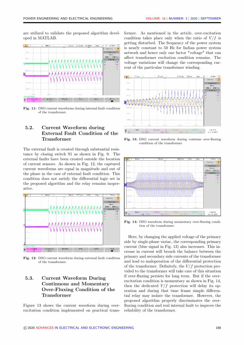
5.1. Current Waveform DuringInternal Fault Condition of theTransformer
The internal fault is created through substantial resis-tance by closing switch S2 as shown in Fig. 9, i.e. on thesecondary terminal of transformer. The internal faultshave been created between two current sensors on thetapping provided on the transformer windings. It hasbeen observed that the current waveforms captured inDSO are in phase during internal fault condition. Thecaptured/sampled current data in *.CSV file of DSOis migrated and buffered into the computer memory.Later, the stored sample data of the hardware currents
© 2020 ADVANCES IN ELECTRICAL AND ELECTRONIC ENGINEERING 185
POWER ENGINEERING AND ELECTRICAL ENGINEERING VOLUME: 18 | NUMBER: 3 | 2020 | SEPTEMBER
are utilized to validate the proposed algorithm devel-oped in MATLAB.
Fig. 11: DSO current waveforms during internal fault conditionof the transformer.
5.2. Current Waveform duringExternal Fault Condition of theTransformer
The external fault is created through substantial resis-tance by closing switch S1 as shown in Fig. 9. Theexternal faults have been created outside the locationof current sensors. As shown in Fig. 12, the capturedcurrent waveforms are equal in magnitude and out ofthe phase in the case of external fault condition. Thiscondition does not satisfy the differential logic set inthe proposed algorithm and the relay remains inoper-ative.
Fig. 12: DSO current waveform during external fault conditionof the transformer.
5.3. Current Waveform DuringContinuous and MomentaryOver-Fluxing Condition of theTransformer
Figure 13 shows the current waveform during over-excitation condition implemented on practical trans-
former. As mentioned in the article, over-excitationcondition takes place only when the ratio of V/f isgetting disturbed. The frequency of the power systemis nearly constant to 50 Hz for Indian power systemnetwork and hence only one factor "voltage" that canaffect transformer excitation condition remains. Thevoltage variations will change the corresponding cur-rent of the particular transformer winding.
Fig. 13: DSO current waveform during continue over-fluxingcondition of the transformer.
Fig. 14: DSO waveform during momentary over-fluxing condi-tion of the transformer.
Here, by changing the applied voltage of the primaryside by single-phase variac, the corresponding primarycurrent (blue signal in Fig. 13) also increases. This in-crease in current will breach the balance between theprimary and secondary side currents of the transformerand lead to maloperation of the differential protectionof the transformer. Definitely, the V/f protection pro-vided to the transformer will take care of this situationif over-fluxing persists for long term. But if the over-excitation condition is momentary as shown in Fig. 14,then the dedicated V/f protection will delay its op-eration and during that time frame simple differen-tial relay may isolate the transformer. However, theproposed algorithm properly discriminates the over-fluxing condition and real internal fault to improve thereliability of the transformer.
© 2020 ADVANCES IN ELECTRICAL AND ELECTRONIC ENGINEERING 186
POWER ENGINEERING AND ELECTRICAL ENGINEERING VOLUME: 18 | NUMBER: 3 | 2020 | SEPTEMBER
The authors have proposed a preventive techniquebased on the fifth harmonic component of the differ-ential current to identify the intensity of the over-excitation condition and, with the help of adaptive ba-sic pickup setting, to retain the false tripping of thetransformer.
Normal Load Line
Bias Current (A)Ibias
Blocking Zone
Operating Zone
Dif
f. Cur
rent
(A
)
Idiff
Id0 A B
C
K1
Idiff /Ibias TrajectoryA B
New Shifted Pickup (Id0new)
Id0new
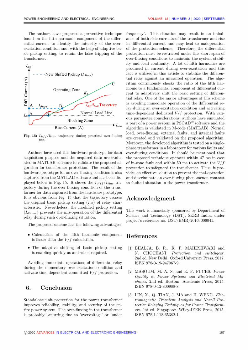
Fig. 15: Idiff/Ibias trajectory during practical over-fluxingtest.
Authors have used this hardware prototype for dataacquisition purpose and the acquired data are evalu-ated in MATLAB software to validate the proposed al-gorithm for transformer protection. The result of thehardware prototype for an over-fluxing condition is alsocaptured from the MATLAB software and has been dis-played below in Fig. 15. It shows the Idiff/Ibias tra-jectory during the over-fluxing condition of the trans-former for data captured from the hardware prototype.It is obvious from Fig. 15 that the trajectory crossesthe original basic pickup setting (Id0) of relay char-acteristic. Nevertheless, the modified pickup setting(Id0new) prevents the mis-operation of the differentialrelay during such over-fluxing situation.
The proposed scheme has the following advantages:
• Calculation of the fifth harmonic componentis faster than the V/f calculation.
• The adaptive shifting of basic pickup settingis enabling quickly as and when required.
Avoiding immediate operations of differential relayduring the momentary over-excitation condition andactivate time-dependent committed V/f protection.
6. Conclusion
Standalone unit protection for the power transformerimproves reliability, stability, and security of the en-tire power system. The over-fluxing in the transformeris probably occurring due to ’overvoltage’ or ’under
frequency’. This situation may result in an imbal-ance of both side currents of the transformer and risein differential current and may lead to maloperationof the protection scheme. Therefore, the differentialprotection must be restricted under this short span ofover-fluxing conditions to maintain the system stabil-ity and load continuity. A lot of fifth harmonics areproduced in current during over-excitation and thisfact is utilized in this article to stabilize the differen-tial relay against an unwanted operation. The algo-rithm continuously checks the ratio of the fifth har-monic to a fundamental component of differential cur-rent to adaptively shift the basic setting of differen-tial relay. One of the major advantages of this schemeis avoiding immediate operation of the differential re-lay during an over-excitation condition and activatingtime-dependent dedicated V/f protection. With vari-ous parameter considerations, authors have simulateda part of a power system in PSCAD™ software and thealgorithm is validated in M-code (MATLAB). Normalload, over-fluxing, external faults, and internal faultsare created and validated on the proposed algorithm.Moreover, the developed algorithm is tested on a single-phase transformer in a laboratory for various faults andover-fluxing conditions. It should be mentioned thatthe proposed technique operates within 47 ms in caseof in-zone fault and within 50 ms to activate the V/fprotection to safeguard the transformer. Thus, it pro-vides an effective solution to prevent the mal-operationand discriminate an over-fluxing phenomenon contrastto faulted situation in the power transformer.
Acknowledgment
This work is financially sponsored by Department ofScience and Technology (DST), SERB India, underproject’s reference no. DST/EMR/2016/006041.
References
[1] BHALJA, B. R., R. P. MAHESHWARI andN. CHOTHANI. Protection and switchgear.2nd ed. New Delhi: Oxford University Press, 2017.ISBN 978-0-19-947067-9.
[2] MASOUM, M. A. S. and E. F. FUCHS. PowerQuality in Power Systems and Electrical Ma-chines. 2nd ed. Boston: Academic Press, 2015.ISBN 978-0-12-800988-8.
[3] LIN, X., Q. TIAN, J. MA and H. WENG. Elec-tromagnetic Transient Analysis and Novell Pro-tective Relaying Techniques for Power Transform-ers. 1st ed. Singapore: Wiley-IEEE Press, 2015.ISBN 978-1-118-65382-1.
© 2020 ADVANCES IN ELECTRICAL AND ELECTRONIC ENGINEERING 187

POWER ENGINEERING AND ELECTRICAL ENGINEERING VOLUME: 18 | NUMBER: 3 | 2020 | SEPTEMBER
[4] IEEE Standard C37.91-2000. IEEE Guide for Pro-tective Relay Applications to Power Transformers.New York: IEEE, 2000.
[5] ZHAO, X., J. CHAI and P. SU. Identification ofmagnetizing inrush currents of power transformersbased on features of flux locus. In: Sixth Interna-tional Conference on Electrical Machines and Sys-tems, 2003. ICEMS 2003. Beijing: IEEE, 2003,pp. 317–320. ISBN 7-5062-6210-X.
[6] KANG, Y.-C., B.-E. LEE, T.-Y. ZHENG,Y.-H. KIM and P. A. CROSSLEY. Protection,faulted phase and winding identification for thethree-winding transformer using the incrementsof flux linkages. IET Generation, Transmission& Distribution. 2010, vol. 4, iss. 9, pp. 1060–1068.ISSN 1751-8695. DOI: 10.1049/iet-gtd.2010.0094.
[7] XU, Y., Z. P. WANG and Q. X. YANG.Study on the improved transformer protectionmethod based on the magnetic flux characteristics.In: 2004 Eighth IEE International Conference onDevelopments in Power System Protection. Ams-terdam: IET, 2004, pp. 360–363. ISBN 0-86341-385-4. DOI: 10.1049/cp:20040137.
[8] KANG, Y. C., S. H. KANG, P. CROSSLEY,S. J. LEE and B. E. LEE. A transformerprotective relaying algorithm using the ratioof the flux linkages. In: 2003 IEEE BolognaPower Tech Conference Proceedings. Bologna:IEEE, 2003, pp. 996–1001. ISBN 0-7803-7967-5.DOI: 10.1109/PTC.2003.1304682.
[9] YAN, X., W. ZENGPING, L. QING and S. GUO-CAI. A novel transformer protection methodbased on the ratio of voltage and fluxional dif-ferential current. In: 2003 IEEE PES Trans-mission and Distribution Conference and Ex-position (IEEE Cat. No.03CH37495). Dallas:IEEE, 2003, pp. 342–347. ISBN 0-7803-8110-6.DOI: 10.1109/TDC.2003.1335245.
[10] AL-FAKHRI, B. A unique transformer pro-tection which eliminates over-voltage, over-fluxing, and CT saturation protection.In: IEEE/PES Transmission and Distribu-tion Conference and Exhibition. Yokohama:IEEE, 2002, pp. 142–147. ISBN 0-7803-7525-4.DOI: 10.1109/TDC.2002.1178274.
[11] DEVIPRIYA, P., T. SNEHA and P. SHAN-MUGAPRIYA. Design of Numerical Relay forOver Flux and Over Current Protection inTransformers. In: 2018 International Conferenceon Computation of Power, Energy, Informa-tion and Communication (ICCPEIC). Chennai:IEEE, 2018, pp. 153–158. ISBN 978-1-5386-2447-0. DOI: 10.1109/ICCPEIC.2018.8525225.
[12] NOSHAD, B. A New Algorithm for Three-PhasePower Transformer Differential Protection Con-sidering Effect of Ultra-Saturation PhenomenonBased on Discrete Wavelet Transform. Interna-tional Journal of Emerging Electric Power Sys-tems. 2019, vol. 20, iss. 1, pp. 1–28. ISSN 1553-779X. DOI: 10.1515/ijeeps-2017-0233.
[13] BHATT, N., S. KAUR and N. TAYAL. Causesand Effects of Overfluxing in Transformers andComparison of Various Techniques for its Detec-tion. In: International Conference on Advancesin Emerging Technology (ICAET 2016). Chennai:IJCA, 2016, pp. 17–22. ISBN 973-93-80892-77-0.
[14] CHEN, K. W. and S. T. GLAD. Estimationof the primary current in a saturated trans-former. In: [1991] Proceedings of the 30th IEEEConference on Decision and Control. Brighton:IEEE, 1991, pp. 2363–2365. ISBN 0-7803-0450-0.DOI: 10.1109/CDC.1991.261872.
[15] MADZIKANDA, E. and M. NEGNEVIT-SKY. A practical look at harmonics in powertransformer differential protection. In: 2012IEEE International Conference on Power Sys-tem Technology (POWERCON). Auckland:IEEE, 2012, pp. 1–6. ISBN 978-1-4673-2868-5.DOI: 10.1109/PowerCon.2012.6401274.
[16] HAMILTON, R. Analysis of Transformer In-rush Current and Comparison of Harmonic Re-straint Methods in Transformer Protection. IEEETransactions on Industry Applications. 2013,vol. 49, iss. 4, pp. 1890–1899. ISSN 1939-9367.DOI: 10.1109/TIA.2013.2257155.
[17] BERNABEU, E. E. Single-Phase TransformerHarmonics Produced During Geomagnetic Dis-turbances: Theory, Modeling, and Monitoring.IEEE Transactions on Power Delivery. 2015,vol. 30, iss. 3, pp. 1323–1330. ISSN 1937-4208.DOI: 10.1109/TPWRD.2014.2371927.
[18] SADEGHKHANI, I., A. KETABI and R. FEUIL-LET. Study of Transformer Switching Over-voltages during Power System RestorationUsing Delta-Bar-Delta and Directed Ran-dom Search Algorithms. International Journalof Emerging Electric Power Systems. 2012,vol. 13, iss. 3, pp. 1–22. ISSN 1553-779X.DOI: https://doi.org/10.1515/1553-779X.2996.
[19] BEHRENDT, K., N. FISCHER andC. LABUSCHAGNE. Considerations for Us-ing Harmonic Blocking and Harmonic RestraintTechniques on Transformer Differential Relays.Journal of Reliable Power. 2011, vol. 2, iss. 3,pp. 1971–1980.
© 2020 ADVANCES IN ELECTRICAL AND ELECTRONIC ENGINEERING 188
POWER ENGINEERING AND ELECTRICAL ENGINEERING VOLUME: 18 | NUMBER: 3 | 2020 | SEPTEMBER
[20] ZHANG, W., Q. TAN, S. MIAO, L. ZHOU andP. LIU. Self-adaptive transformer differential pro-tection. IET Generation, Transmission & Distri-bution. 2013, vol. 7, iss. 1, pp. 61–68. ISSN 1751-8695. DOI: 10.1049/iet-gtd.2011.0739.
[21] NIMKAR, P. R., T. G. ARORA, P. S. BANGDEand P. J. NARNAWARE. Over-Flux Protec-tion of The Transformer. In: 2018 Interna-tional Conference on Smart Electric Drives andPower System (ICSEDPS). Nagpur: IEEE,2018, pp. 171–176. ISBN 978-1-5386-5793-5.DOI: 10.1109/ICSEDPS.2018.8536055.
[22] MAHESHWARI, R. P. and H. K. VERMA. Adap-tive digital differential relay with overexcitationand inrush restraint. Electric Power Systems Re-search. 1997, vol. 41, iss. 3, pp. 175–184. ISSN0378-7796. DOI: 10.1016/S0378-7796(96)01153-4.
[23] CHOTHANI, N. G. Development and Testing ofa New Modified Discrete Fourier Transform-basedAlgorithm for the Protection of Synchronous Gen-erator. Electric Power Components and Systems.2016, vol. 44, iss. 14, pp. 1564–1575. ISSN 1532-5016. DOI: 10.1080/15325008.2016.1181688.
[24] IEEE Standard C37.91-2008. IEEE Guide for Pro-tecting Power Transformers. New York: IEEE,2008.
About Authors
Maulik RAICHURA is a Research Scholar in theDepartment of Electrical Engineering, Gujarat Tech-nological University, Gujarat, India. He received hisB.E. degree from A.D. Patel Institute of Technology,New Vallabh Vidhyanagar, Gujarat, India in 2014and Master degree in power system from the ShantilalShah Engineering College, Bhavnagar, Gujarat, Indiain 2016. Currently, he is pursuing his Ph.D. fromGujarat Technological University, Gujarat, India.
Nilesh CHOTHANI is an associate professorat Adani Institute of Infrastructure Engineering,GTU. He received his B.E. degree from SaurashtraUniversity, Rajkot, India in 2001. He received Masterdegree in power system and the Ph.D. degree inelectric engineering from the Sardar Patel University,Vallabh Vidhyanagar, Anand, India in 2004 and 2013,respectively. His research interests include powersystem protection, simulation, power system modelingand artificial intelligence.
Dharmesh PATEL received his B.E. degreefrom North Gujarat University, Patan, Gujarat in1999 and Master degree in power system from theSardar Patel University, Vallabh Vidhyanagar, Anand,India in 2002. He has received his Ph.D. degree fromSardar Vallabhbhai National Institute of Technology,Surat, India in 2019. His field of research is powertransformer protection.
© 2020 ADVANCES IN ELECTRICAL AND ELECTRONIC ENGINEERING 189