an amplitude-preserved adaptive focused beam seismic ... · pdf fileoriginal paper an...
TRANSCRIPT
ORIGINAL PAPER
An amplitude-preserved adaptive focused beam seismic migrationmethod
Ji-Dong Yang1 • Jian-Ping Huang1 • Xin Wang1 • Zhen-Chun Li1
Received: 6 February 2015 / Published online: 23 July 2015
� The Author(s) 2015. This article is published with open access at Springerlink.com
Abstract Gaussian beam migration (GBM) is an effec-
tive and robust depth seismic imaging method, which
overcomes the disadvantage of Kirchhoff migration in
imaging multiple arrivals and has no steep-dip limitation of
one-way wave equation migration. However, its imaging
quality depends on the initial beam parameters, which can
make the beam width increase and wave-front spread with
the propagation of the central ray, resulting in poor
migration accuracy at depth, especially for exploration
areas with complex geological structures. To address this
problem, we present an adaptive focused beam method for
shot-domain prestack depth migration. Using the infor-
mation of the input smooth velocity field, we first derive an
adaptive focused parameter, which makes a seismic beam
focused along the whole central ray to enhance the wave-
field construction accuracy in both the shallow and deep
regions. Then we introduce this parameter into the GBM,
which not only improves imaging quality of deep reflectors
but also makes the shallow small-scale geological struc-
tures well-defined. As well, using the amplitude-preserved
extrapolation operator and deconvolution imaging condi-
tion, the concept of amplitude-preserved imaging has been
included in our method. Typical numerical examples and
the field data processing results demonstrate the validity
and adaptability of our method.
Keywords Gaussian beam � Adaptive focused beam �Amplitude-preserved migration � Depth imaging
1 Introduction
With the development of petroleum exploration, seismic
surveys have gradually extended into areas with complex
geological conditions, such as regions with continental
faulted basins and offshore salt deposits. This situation
presents new challenges for seismic imaging, which com-
pel us to explore a more efficient, accurate, and robust
migration method than the existing ones.
Over the past decades, dramatical progress has been
achieved in the field of prestack depth imaging. Ray-based
Kirchhoff migration has been developed from 2D to 3D
(Hubral et al. 1996; Epili and McMechan 1996; Sun et al.
2000), from single-arrival migration (including first arrival,
most energy arrival etc.) to multi-arrival migration
(Brandsberg-Dahl et al. 2001; Xu et al. 2001) and from
kinematic migration to true-amplitude migration (Schle-
icher et al. 1993; Albertin et al. 1999; Xu and Lambare
2006). Due to its high efficiency and flexibility, Kirchhoff
migration is still the workhorse in practical applications,
especially for land seismic data. On the other hand, one-
way wave equation migration accuracy has also been
improved significantly using different numerical algo-
rithms, such as split-step Fourier, Fourier finite difference,
and generalized screen propagator (Stoffa et al. 1990;
Ristow and Ruhl 1994; Chen and Ma 2006; Li et al. 2008;
Kaplan et al. 2010; Huang and Fehler 2000; Liu and Yin
2007; Zhu et al. 2009; De Hoop et al. 2000; Wu et al. 2001;
Le Rousseau and De Hoop 2003; Liu et al. 2012). Reverse
time migration based on two-way wave equations has
become more and more practical in actual projects as
& Ji-Dong Yang
1 School of Geoscience, China University of Petroleum,
Qingdao 266580, Shandong, China
Edited by Jie Hao
123
Pet. Sci. (2015) 12:417–427
DOI 10.1007/s12182-015-0044-7

computer technology develops (Baysal et al. 1983), and
many geophysicists have provided lots of constructive
suggestions about the problems of time-consuming defects
and low frequency imaging noise (Fletcher et al. 2006;
Symes 2007; Chattopadhyay and McMechan 2008;
Abdelkhalek et al. 2009; Li et al. 2010).
Gaussian beam migration (GBM) is an elegant and
effective depth imaging method, which not only retains the
advantage of ray-based migration, such as flexibility and
efficiency, but also has an imaging accuracy comparable
with wave equation migration. Ever since the basic
framework of GBM was presented by Hill (1990, 2001), it
has been extended to irregular topographic conditions
(Gray 2005; Yue et al. 2012; Yang et al. 2014) and true-
amplitude migration (Gray and Bleistein 2009). In addi-
tion, many new seismic beam imaging methods have been
developed, such as fast beam migration (Gao et al. 2006,
2007), focused beam migration (Nowack 2008), and laser
beam migration (Xiao et al. 2014), which expand the
members of the beam migration family. Most of them,
however, are based on the GBM framework and use a
constant initial beam parameter, which makes a seismic
beam focused either at the initial position or at a certain
depth. Thus, the imaging accuracy varies along the central
ray, highest at the focus point and decreasing as moving
away from the focus point.
Aiming at this problem, Nowack (2009) has provided a
dynamically focused beam method, which improves the
deep imaging quality to some extent. Because this method
is achieved using a unified beam width for all the subsur-
face imaging points and performing many local slant stacks
and quadratic phase corrections for each beam, it does not
consider the effects of velocity variation on the beam width
and is very time-consuming. Hu and Stoffa (2009) have
implemented a modified GBM for low-fold seismic data
acquired sparsely, utilizing the instantaneous slowness of
the local plane wave. Derived from the Maslov wave
equation solution, Zhu (2009) also proposed a complex-ray
beam method for exploration areas with complex topog-
raphy. All methods mentioned above use the Fresnel zone
information to limit the seismic beam energy and improve
the imaging quality, which provides new options for beam
migration.
In this paper, we have proposed another way to optimize
the beam propagation shape and implemented an adaptive
focused beam migration method for common-shot data,
which could improve the shallow and deep imaging quality
simultaneously. Using the information of the input
smoothed velocity field, we derived an adaptive focused
parameter that makes a seismic beam focused at the whole
central ray, and then use it to construct a Green function in
the acoustic medium and to solve the seismic migration
problem. Unlike the dynamically focused beam method
proposed by Nowack, our method uses the single input-
trace imaging approach of classic Kirchhoff migration to
avoid repeating local slant stacks for a beam at different
imaging points, which is helpful to speed up the migration
process. However, compared with Hill’s GBM, there is a
tradeoff in computational efficiency, as now the number of
emergent beams increases. In addition, using the ampli-
tude-preserved extrapolation formula and deconvolution
imaging condition, we have included the concept of
amplitude-preserved imaging in our method. Typical
numerical examples and the field data processing results
demonstrate the feasibility and validity of the proposed
method.
2 Theory
2.1 Adaptive focused beam
Considering a Gaussian beam from Qðs0; 0Þ to Pðs; 0Þ in a
2D acoustic medium, its ray propagation matrix can be
written as
pðs; s0Þ ¼q1ðsÞ q2ðsÞp1ðsÞ p2ðsÞ
� �; ð1Þ
where ðs; nÞ are ray-centered coordinates as shown in
Fig. 1, ðp1ðsÞ; q1ðsÞÞ and ðp2ðsÞ; q2ðsÞÞ are two fundamen-
tal solutions of dynamic ray tracing equation system
(Cerveny et al. 1982).
If the beam focused at P and its beam width equals lðsÞ,then the complex dynamic parameter at the initial position
can be calculated by
qðs0Þpðs0Þ
� �¼ pðs; s0Þ�1 �ixref l
2ðsÞ1
� �; ð2Þ
here xref denotes the referenced frequency, i ¼ffiffiffiffiffiffiffi�1
pand
lðsÞ takes the following form
lðsÞ ¼ 2pvðsÞ=xref ; ð3Þ
where vðsÞ is the velocity of central ray.
Further, using the relation
(s,n)O(s0,0)
nr
P(s, 0)
τr
Fig. 1 Ray-centered coordinate system
418 Pet. Sci. (2015) 12:417–427
123

e ¼ qðs0Þ=pðs0Þ; ð4Þ
We obtain a new initial beam parameter
eðsÞ ¼ �q2ðsÞ � ixref l2ðsÞp2ðsÞ
q1ðsÞ þ ixref l2ðsÞp1ðsÞ: ð5Þ
Unlike the Gaussian beam and focused beam, the initial
parameter in Eq. (5) is no longer a constant, but a function
of ray arc length. This choice makes the main energy of
the beams focus in the range of a wavelength along the
whole ray. For the convenience of discussion, we define
the beam determined by eðsÞ in Eq. (5) as the adaptive
focused beam.
Now we analyze the propagation property of the adap-
tive focused beam briefly. Considering an inhomogeneous
medium as shown in Fig. 2a, which includes a high-speed
layer and a low-speed layer in a constant-gradient velocity
background, the adaptive focused beam keeps a narrow
beam width and plane wave-front along the whole central
ray (see Fig. 2b). Besides, it has a small beam width at the
low-speed layer and large beam width at the high-speed
layer marked by the blue ellipses in Fig. 2b, which is
helpful to resolve the steep-dip reflectors and velocity
abnormal bodies in seismic imaging. For a Gaussian beam,
however, the beam width increases quickly and the wave-
front diffuses rapidly (see Fig. 2c), which result in inac-
curate travel-time and amplitude extrapolated from central
ray at deep parts, especially in a medium with strong lateral
velocity variation.
2.2 Green function represented with the adaptive
focused beam integral
With the initial parameter eðsÞ in Eq. (5), we can write the
expression of the adaptive focused beam in the frequency
domain as
Uðs; n;xÞ ¼
ffiffiffiffiffiffiffiffiffiffiffiffiffiffiffiffiffiffiffiffiffiffiffiffiffiffiffiffiffiffiffiffiffiffiffiffiffiffiffiffiffiffiffiffiffiffieðs0ÞvðsÞ
eðsÞq1ðsÞ þ q2ðsÞ½ �vðs0Þ
s
� exp ix sðsÞ þ 1
2
eðsÞp1ðsÞ þ p2ðsÞeðsÞq1ðsÞ þ q2ðsÞ
n2� �� �
:
ð6Þ
where x denotes the circular frequency, s is the travel-time
of central ray.
According to Muller (1984), Green’s function at pointM
shown in Fig. 3 can be approximately represented with an
integral over all the rays of beams, i.e.,
GðM;xÞ ¼Z/0þp=2
/0�p=2
Uð/; sÞU/ðs; n;xÞd/; ð7Þ
where Uð/; sÞ is an integral weight coefficient for the
adaptive focused beam with emergence angle /.If the weight coefficientUð/; sÞwas known, Eq. (7) could
be used to calculate the seismic wave-field at any point of the
medium. Now we determine the function Uð/; sÞ in a
homogenous medium with constant velocity v0. Denoting
Fð/Þ ¼ Uð/; sÞ
ffiffiffiffiffiffiffiffiffiffiffiffiffiffiffiffiffiffiffiffiffiffiffiffiffiffiffiffiffiffiffiffiffiffiffiffiffiffiffiffiffiffiffiffiffiffiffiffiffiffiffieð/; s0ÞvðsÞ
eð/; sÞq1ðsÞ þ q2ðsÞ½ �vðs0Þ
s
f ð/Þ ¼ �i sðsÞ þ 1
2
eð/; sÞp1ðsÞ þ p2ðsÞeð/; sÞq1ðsÞ þ q2ðsÞ
n2� �
:
ð8Þ
Equation (7) can be rewritten as
GðM;xÞ ¼Z/0þp=2
/0�p=2
Fð/Þ exp �xf ð/Þ½ �d/: ð9Þ
In a homogeneous medium, we have (see Fig. 3)
sðsÞ ¼ r cosð/� /0Þ=v0; n ¼ r sinð/� /0Þq1 ¼ p2 ¼ 1; p1 ¼ 0; q2 ¼ v0r cosð/� /0Þ:
ð10Þ
0
1
2
3
4
5
Dep
th, k
m
Distance, km0 1 2 3 4 5
0
1
2
3
4
5
Dep
th, k
m
Distance, km
1500
2000
2500
3000
3500
m/s
0 1 2 3 4 50
1
2
3
4
5
Dep
th, k
m
Distance, km0 1 2 3 4 5
(a) (b) (c)
Fig. 2 The propagation of different seismic beams. a Velocity model, b adaptive focused beam, c Gaussian beam
Pet. Sci. (2015) 12:417–427 419
123

Inserting the latter expression in the Eq. (8), we obtain
Fð/Þ ¼Uð/; sÞ
ffiffiffiffiffiffiffiffiffiffiffiffiffiffiffiffiffiffiffiffiffiffiffiffiffiffiffiffiffiffiffiffiffiffiffiffiffiffiffiffiffiffiffiffiffiffiffiffieð/; s0Þ
eð/; sÞþ v0r cosð/�/0Þ
s
f ð/Þ ¼�i r cosð/�/0Þ=v0þ1
2
r2 sin2ð/�/0Þeð/; sÞþ v0r cosð/�/0Þ
� �:
ð11Þ
In a smoothed medium, e/ ð/; sÞ can be expanded with
Taylor’s formula as follows
eð/; sÞ ¼ eð/0; sÞ þ e/ð/0; sÞð/� /0Þ; ð12Þ
where e/ð/0; sÞ denotes the partial derivative of eð/0; sÞwith respect to /.
It is easy to see from Eq. (11) that the saddle point of
Eq. (9), defined by f/ð/Þ ¼ 0, is / ¼ /0. So we assume
that in the vicinity of /0, which contributes most to Eq. (9),
Uð/; sÞ can be replaced by Uð/0; sÞ. Then, the corre-
sponding approximation of Fð/Þ and f ð/Þ takes the form
Fð/Þ¼Uð/0;sÞffiffiffiffiffiffiffiffiffiffiffiffiffiffiffiffiffiffiffiffiffiffiffiffiffiffiffiffiffiffiffiffiffiffiffiffiffiffiffiffiffiffiffiffiffiffiffiffiffiffiffiffiffiffiffiffiffiffiffiffiffiffiffieð/0;s0Þþe/ð/0;s0Þð/�/0Þ
eð/0;sÞþe/ð/0;sÞð/�/0Þþv0r
s
f ð/Þ¼�ir
v0þ ir
2v0
eð/0;sÞð/�/0Þ2
eð/0;sÞþv0rþv0re/ð/0;sÞð/�/0Þ3
eð/0;sÞþv0r½ �2
( ):
ð13Þ
Under the far-field condition, the latter expressions can
be further reduced to
Fð/Þ ¼Uð/0; sÞ
ffiffiffiffiffiffiffiffiffiffiffiffiffiffiffiffiffiffiffiffiffiffiffiffiffiffiffiffiffiffiffiffiffiffiffiffiffiffiffiffiffiffiffiffiffiffiffiffiffiffiffiffiffiffiffiffiffiffieð/0; s0Þþ e/ð/0; s0Þð/�/0Þ
v0r
s
f ð/Þ ¼�ir
v0þ i
2v20eð/0; sÞð/�/0Þ2þ e/ð/0; sÞð/�/0Þ3h i
:
ð14Þ
Therefore, we obtain the approximate expression of
Green’s function represented by the adaptive focused beam
integral as
Gðr;/0Þ � Uð/0; sÞexpðixr=v0Þffiffiffiffiffiffiffi
v0rp H; ð15Þ
where
H ¼Z/0þp=2
/0�p=2
d/ eð/0; sÞ þ e/ð/0; sÞð/� /0Þ� �1=2
expix
2v20eð/0; sÞð/� /0Þ
2 þ e/ð/0; sÞð/� /0Þ3
h i :
ð16Þ
Comparing Eq. (15) with the leading term in the
expansion of Green’s function obtained by asymptotic ray
theory (ART):
G � exp ixr=v0 þ isgnðxÞp=4½ �2
ffiffiffiffiffiffiffiffiffiffiffiffiffiffiffiffiffiffi2p xj jr=v
p ; ð17Þ
we obtain
Uð/0; sÞ ¼v0 expðisgnðxÞp=4Þ
2ffiffiffiffiffiffiffiffiffiffiffiffi2p xj j
pH
: ð18Þ
In order to simplify the integral of Eq. (16), here we
consider two extreme cases:
Case 1 e/ð/0; sÞ ¼ 0; eð/0; sÞ 6¼ 0
H ¼ v0
ffiffiffiffiffiffi2pix
r; Uð/0; sÞ ¼
i
4pð19Þ
Case 2 e/ð/0; sÞ 6¼ 0; eð/0; sÞ ¼ 0;
H ¼ 2
3v0
ffiffiffiffiffiffi2pix
r; Uð/0; sÞ ¼
i
6pð20Þ
Case (1) means there is no variation of eð/; sÞ in the
neighborhood of /0, and the corresponding integral coef-
ficient is consistent with that proposed by Cerveny et al.
(1982). Case (2) means there is strong variation of eð/; sÞaround /0, but the integral coefficient in this case is only
the 2/3 times of that of case (1), which means Uð/0; sÞ hasonly a relatively mild dependence on the beam parameter
eð/; sÞ. Thus, it appears reasonable to use the results of
case (1), and we obtain the expression of Green’s function
represented by the adaptive focused beam integral
GðM;xÞ ¼ i
4p
Z/0þp=2
/0�p=2
U/ðs; n;xÞd/: ð21Þ
In order to demonstrate the validity of Eq. (21), we
compare it with the analytic Green’s function calculated
with ART in a homogeneous medium, where the velocity is
M
P
S
Ray Ω
r = SM
n = MP
Ф−Ф0
s = SP
Ray Ω0
Fig. 3 Green’s function constructed with adaptive focused beam
summation (referenced to Cerveny et al. 1982)
420 Pet. Sci. (2015) 12:417–427
123

2000 m/s and the reference frequency and the data fre-
quency are all 10 Hz. The results are shown in Fig. 4. It is
easy to see that both the real and imaginary parts of the
Green’s function calculated with the two methods are
similar for most distances, except the real part in the
shallow zone marked by the green arrow. One possible
explanation is that an adaptive focused beam appears a
plane wave at the initial point and its beam width is about a
wavelength, which is not consistent with the point source
wave-field calculated with Eq. (17). But the near-source
error can be neglected in practical seismic modeling and
imaging applications.
2.3 Adaptive focused beam migration formula
Nowack (2009) has used many local slant stacks and
quadratic phase corrections for every beam in the dynam-
ically focused beam migration, which is time-consuming
and complex in designing the implementation algorithm.
Here we adopt the single input-trace imaging approach of
classical Kirchhoff migration to implement the adaptive
focused migration. As a result, our method is more com-
puter intensive than Hill’s method, but it is more efficient
than Nowack’s method and can be accepted given the
current level of computer power for an accurate depth
image of subsurface geological structures.
The main point of our method is replacing the Green’s
function by its approximate form in terms of the adaptive
focused beam integral. From the latter section, we know
the Green’s function from x0 to x can be written as
Gðx; x0;xÞ ¼ i
4p
Zd/Aðx; x0Þ exp ixTðx; x0Þ½ �: ð22Þ
Here Aðx; x0Þ and Tðx; x0Þ are the complex amplitude
and travel-time of the adaptive focused beam respectively,
and they have the following form
Aðx; x0Þ ¼
ffiffiffiffiffiffiffiffiffiffiffiffiffiffiffiffiffiffiffiffiffiffiffiffiffiffiffiffiffiffiffiffiffiffiffiffiffiffiffiffiffiffiffiffiffiffiffieðx0ÞvðxÞ
eðxÞq1ðxÞ þ q2ðxÞ½ �vðx0Þ
s
Tðx; x0Þ ¼ sðx; x0Þþ 1
2
eðxÞp1ðxÞ þ p2ðxÞeðxÞq1ðxÞ þ q2ðxÞ
n2x;
ð23Þ
where eðxÞ is the adaptive focused beam parameter defined
in Eq. (5).
According to the true-amplitude GBM formula pre-
sented by Gray and Bleistein (2009), the up-going and
down-going wave-fields can be written as
PUðxP;xS;xÞ¼�2ixZ
drcos/R
vRG�ðxP;xR;xÞPUðxR;xS;xÞ
PDðxP;xS;xÞ¼�2ixcos/S
vSGðxP;xS;xÞ;
ð24Þ
where xS, xR; and xP are the Cartesian coordinates of
source, receiver, and imaging point, respectively, /S and
/R are the ray emergence angles from surface at source and
receiver (see Fig. 5), PUðxR; xS;xÞ is the recorded wave-
field, vS and vR are the velocity at source and receiver
separately, ‘‘*’’ denotes the complex conjugate.
Inserting Eq. (22) into Eq. (24) and using the decon-
volution imaging condition
RðxP; xSÞ ¼ 1
2pcos/S
vS
Zdxix
PUðxP; xS;xÞP�DðxP; xS;xÞ
PDðxP; xS;xÞP�DðxP; xS;xÞ
:
ð25Þ
0 500 1000 1500 2000 2500 3000 3500 4000-1.5
-1
-0.5
0
0.5
1
Distance, m
Am
plitu
de
ARTAdaptive Focused Beam
0 500 1000 1500 2000 2500 3000 3500 4000-2.5
-2
-1.5
-1
-0.5
0
0.5
1
Distance, m
Am
plitu
de
ARTAdaptive Focused Beam
(a) (b)
Fig. 4 Real (a) and imaginary (b) parts of Green’s function calculated with ART and adaptive focused beam methods
Pet. Sci. (2015) 12:417–427 421
123

We obtain the shot-domain adaptive focused beam
migration formula
RðxP; xSÞ ¼ �1
8p3cos/S
vS
Zdx
Zdr
ix3
PDP�D
ZZd/Sd/R
� cos/S
vScos/R
vRA�SA
�R exp �ixT�ð ÞPUðxR; xS;xÞ:
ð26Þ
To reduce the computational cost, Gray and Bleistein
(2009) used the stationary-phase approximation to simplify
the double integral about the emergence angles of source
and receiver. Here we adopt this accelerating strategy.
Denoting
/m ¼ /S þ /R
/h ¼ /R � /S;ð27Þ
Equation (26) can be rewritten as
RðxP; xSÞ ¼ �1
16p3cos/S
vS
Zdx
Zdr
ix3
PDP�D
ZZd/md/h
� cos/S
vScos/R
vRA�SA
�R exp �ixT�ð ÞPUðxR; xS;xÞ:
ð28Þ
Further, using the stationary-phase approximation to
calculate the inner integral with respect to /h and the term
of source illumination PDP�D, we obtain the final adaptive
focused beam migration formula
RðxP; xSÞ ¼ �1
4pffiffiffiffiffiffi2p
pZ
dxZ
drffiffiffiffiffiix
pxZ
d/m exp �ixT�ð Þ
� cos/S
vS
� �2cos/R
vRA�SA
�R
ASj j2T 00S ð/
S0Þ
�� ��ffiffiffiffiffiffiffiffiffiffiffiffiffiffiffiffiT�00ð/h
0Þq PUðxR; xS;xÞ;
ð29Þ
where
T ¼ TðxP; xSÞ þ TðxP; xRÞ
T 00S ð/
S0Þ ¼
qðxSÞq2ðxPÞqðxPÞv2ðxSÞ
� �
T�00ð/h0Þ ¼
qðxSÞq2ðxPÞqðxPÞv2ðxSÞ þ
qðxRÞq2ðxPÞqðxPÞv2ðxRÞ
� ��;
ð30Þ
/h0 is the stationary value, i.e., when /m is fixed, /h
0 min-
imizes the imaginary part of the total time T. /S0 and /
R0 are
the corresponding emergence angles of source and receiver
determined by Eq. (27).
3 Numerical examples
We present a hierarchy of numerical examples in this
section. First, we use a simple horizontal layered model to
test the amplitude-preserved property of the proposed
method. Then, we carry out two applications of this method
to the Marmousi dataset and the field data of a survey in
East China, respectively.
To show how the adaptive focused beam migration
works, we first apply it to a layered model in a medium
with constant velocity of 2000 m/s, which simulates
reflections from density contrasts as shown in Fig. 6a.
Three horizontal reflectors with identical reflection coeffi-
cients are placed at depths of 2000, 3000, and 4000 m. A
common-shot record shown in Fig. 6b, with a recording
aperture of 3750 m on either side of the source, is migrated
with our method, and the result is displayed in Fig. 6c. The
normalized migration amplitude of reflectors and distances
is shown in Fig. 7. Half-opening angles were limited to 50�in the migration.
It is easy to see that the proposed method has eliminated
the influences of offset and images the reflectors accurately
(see Fig. 6c). On the other hand, the amplitude-preserved
extrapolation formula and deconvolution imaging condi-
tions have eliminated the reflection amplitude difference
caused by the different incident angles (see Fig. 7a) and
compensated the deep energy loss caused by geometric
spreading (see Fig. 7b), leading to the migration amplitude
being proportional to the vertical reflection coefficients in
effective aperture. Migration aperture truncation artifacts
marked by red arrows in Fig. 7a begin to interfere with the
amplitudes at the distance corresponding to half-opening
angles approaching 50�.The second example is a synthetic dataset from the 2D
Marmousi model as shown in Fig. 8a. The model is about
9.2 km long and 3 km deep, and is characterized by strong
lateral velocity variations that cause complicated multi-
pathing of the seismic energy. Because the smoothed
velocity is required in ray-based migration for numerical
S R
P SourceReceivers
Surface
Φs ΦR
Fig. 5 Scheme of adaptive focused beam migration
422 Pet. Sci. (2015) 12:417–427
123

stability in ray tracing, here we use a damped least squares
algorithm to smooth the velocity (see Fig. 8b), which
permits us to specify the degree of smoothing of the first-
and second-order derivatives of the velocity (Popov et al.
2010). The depth images migrated with the Kirchhoff
method and GBM with different initial widths l0, one-way
6 70
1
2
3
4
5
Tim
e, s
Distance, km0 1 2 3 4 5 6 7
(b)
0
1
2
3
4
5
Dep
th, k
m
Distance, km0 1 2 3 4 5
(c)
0
1
2
3
4
5
Dep
th, k
mDistance, km
0 1 2 3 4 5 6 7
(a)
2.00 g/cm3
2.10 g/cm3
2.21 g/cm3
2.32 g/cm3
Fig. 6 Layered model and its migration result. a Density model, b single-shot record, c depth image migrated with the proposed method
0 1 2 3 4 5 6 7 8-0.5
0
0.5
1
1.5
Distance, km
Am
plitu
de
Layer1=2,000 mLayer2=3,000 mLayer3=4,000 m
(a)
-1 0 1
0
1000
2000
3000
4000
5000
Amplitude
Dep
th, m
-1 0 1
0
1000
2000
3000
4000
5000
AmplitudeD
epth
, m-1 0 1
0
1000
2000
3000
4000
5000
Amplitude
Dep
th, m
(b)
Dis=2.25km Dis=3.75km Dis=5.25km
Fig. 7 Normalized amplitude along reflectors (a) and at different distances (b) in Fig. 6c
0
1
2
Dep
th, k
m
0 2 4 6 8
Distance, km
1300
2300
3300
4300
5300
0
1
2
Dep
th, k
m
0 2 4 6 8
Distance, km
1300
2300
3300
4300
5300
3
m/s m/s
3
9.2 9.2(a) (b)
Fig. 8 Marmousi model: a the velocity used for simulation, b the smoothed velocity used for migration
Pet. Sci. (2015) 12:417–427 423
123

wave equation migration and the proposed method are
shown in Fig. 9, where the migration aperture is about
5 km and frequency range is from 5 to 60 Hz.
In general, all four methods have imaged the three main
faults, pinch-outs, and the anticline at the bottom of the
model. The Kirchhoff result shows lots of swing noise in
0
1
2
Dep
th, k
m9
Distance, km2 3 4 5 6 7 8
3
(a)
0
1
2
Dep
th, k
m
9Distance, km
2 3 4 5 6 7 8
3
(d)0
1
2
Dep
th, k
m
9Distance, km
2 3 4 5 6 7 8
3
(c)
0
1
2
Dep
th, k
m
9Distance, km
2 3 4 5 6 7 8
3
(e)0
1
2
Dep
th, k
m
9Distance, km
2 3 4 5 6 7 8
3
(f)
0
1
2
Dep
th, k
m
9Distance, km
2 3 4 5 6 7 8
3
(b)
Fig. 9 Depth images migrated from the Marmousi dataset: a Kirchhoff migration, b GBM with l0 ¼ 0:25kavg, c GBM with l0 ¼ kavg, d GBM
with l0 ¼ 2kavg, e one-way wave equation migration, f adaptive focused beam migration. kavg denotes the average wavelength of the input
velocity field and the reference frequency for GBM and our method is 10 Hz
424 Pet. Sci. (2015) 12:417–427
123

the central deep parts with large lateral velocity variation,
which blurs the steep-dip fault boundaries and the anticline
(marked by blue arrows and green rectangle in Fig. 9a).
Figure 9b–d shows the effects of the initial width on the
imaging quality of GBM. It is noticed that both the shallow
and the deep structures are blurred and destroyed in the
image with initial width l0 = 2kavg (see the blue arrows
and green rectangle in Fig. 9b). The reason is that the large
initial width of the Gaussian beam makes its travel-time
and amplitude extrapolation inaccurate in the vicinity of
the whole ray. The migrated result with initial width l0= kavg (the parameter proposed by Hill) appears relatively
cleaner at depth, but small-scale geological structures in
the shallow part are not defined well (see the blue arrows in
-1 -0.5 0 0.5 1
0
0.5
1
1.5
2
2.5
3
Amplitude
Dep
th, k
m
Dis=6.25 km
Mig
Ref
-1 -0.5 0 0.5 1
0
0.5
1
1.5
2
2.5
3
Amplitude
Dep
th, k
m
Dis=8.75 km
Mig
Ref
-1 -0.5 0 0.5 1
0
0.5
1
1.5
2
2.5
3
Amplitude
Dep
th, k
mDis=3.75 km
Mig
Ref
Fig. 10 Comparison of the vertical reflection coefficient (the green line) with migration result produced with our method (the blue line) for the
Marmousi model
0
1
2
3
4
5
6
Dep
th, k
m
10
Distance, km0 2 4 6 8
2000
3000
4000
m/s
0
1
2
3
4
5
6
Tim
e, s
10 20 30 40 50 60Trace number
1(a) (b)
Fig. 11 A seismic survey in east China: a velocity model, b a single-shot record
Pet. Sci. (2015) 12:417–427 425
123
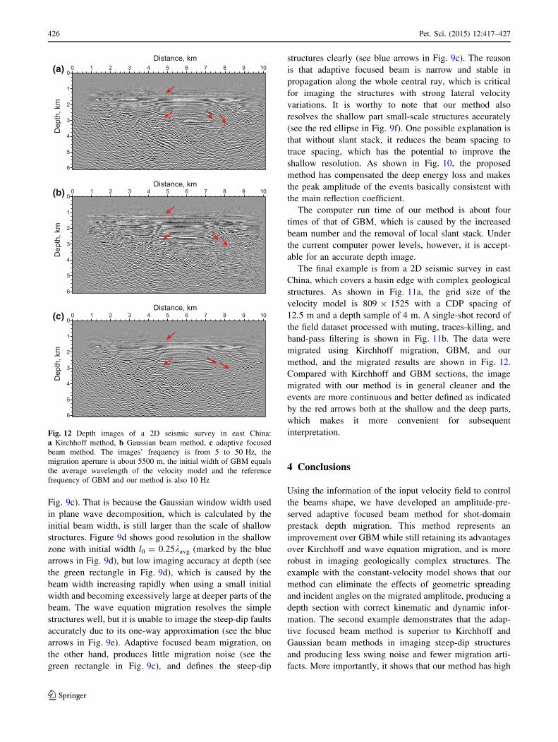
Fig. 9c). That is because the Gaussian window width used
in plane wave decomposition, which is calculated by the
initial beam width, is still larger than the scale of shallow
structures. Figure 9d shows good resolution in the shallow
zone with initial width l0 = 0.25kavg (marked by the blue
arrows in Fig. 9d), but low imaging accuracy at depth (see
the green rectangle in Fig. 9d), which is caused by the
beam width increasing rapidly when using a small initial
width and becoming excessively large at deeper parts of the
beam. The wave equation migration resolves the simple
structures well, but it is unable to image the steep-dip faults
accurately due to its one-way approximation (see the blue
arrows in Fig. 9e). Adaptive focused beam migration, on
the other hand, produces little migration noise (see the
green rectangle in Fig. 9c), and defines the steep-dip
structures clearly (see blue arrows in Fig. 9c). The reason
is that adaptive focused beam is narrow and stable in
propagation along the whole central ray, which is critical
for imaging the structures with strong lateral velocity
variations. It is worthy to note that our method also
resolves the shallow part small-scale structures accurately
(see the red ellipse in Fig. 9f). One possible explanation is
that without slant stack, it reduces the beam spacing to
trace spacing, which has the potential to improve the
shallow resolution. As shown in Fig. 10, the proposed
method has compensated the deep energy loss and makes
the peak amplitude of the events basically consistent with
the main reflection coefficient.
The computer run time of our method is about four
times of that of GBM, which is caused by the increased
beam number and the removal of local slant stack. Under
the current computer power levels, however, it is accept-
able for an accurate depth image.
The final example is from a 2D seismic survey in east
China, which covers a basin edge with complex geological
structures. As shown in Fig. 11a, the grid size of the
velocity model is 809 9 1525 with a CDP spacing of
12.5 m and a depth sample of 4 m. A single-shot record of
the field dataset processed with muting, traces-killing, and
band-pass filtering is shown in Fig. 11b. The data were
migrated using Kirchhoff migration, GBM, and our
method, and the migrated results are shown in Fig. 12.
Compared with Kirchhoff and GBM sections, the image
migrated with our method is in general cleaner and the
events are more continuous and better defined as indicated
by the red arrows both at the shallow and the deep parts,
which makes it more convenient for subsequent
interpretation.
4 Conclusions
Using the information of the input velocity field to control
the beams shape, we have developed an amplitude-pre-
served adaptive focused beam method for shot-domain
prestack depth migration. This method represents an
improvement over GBM while still retaining its advantages
over Kirchhoff and wave equation migration, and is more
robust in imaging geologically complex structures. The
example with the constant-velocity model shows that our
method can eliminate the effects of geometric spreading
and incident angles on the migrated amplitude, producing a
depth section with correct kinematic and dynamic infor-
mation. The second example demonstrates that the adap-
tive focused beam method is superior to Kirchhoff and
Gaussian beam methods in imaging steep-dip structures
and producing less swing noise and fewer migration arti-
facts. More importantly, it shows that our method has high
0
1
2
3
4
5
6
Dep
th, k
m0 1 2 3 4 5 6 7 8 9 10
Distance, km
0
1
2
3
4
5
6
Dep
th, k
m
0 1 2 3 4 5 6 7 8 9 10
0
1
2
3
4
5
6
Dep
th, k
m
0 1 2 3 4 5 6 7 8 9 10Distance, km
(a)
(b)
(c)
Distance, km
Fig. 12 Depth images of a 2D seismic survey in east China:
a Kirchhoff method, b Gaussian beam method, c adaptive focused
beam method. The images’ frequency is from 5 to 50 Hz, the
migration aperture is about 5500 m, the initial width of GBM equals
the average wavelength of the velocity model and the reference
frequency of GBM and our method is also 10 Hz
426 Pet. Sci. (2015) 12:417–427
123

shallow resolution, which is helpful to define the shallow
small-scale geological structures. The example of field data
processing further confirms the conclusions obtained from
the previous two examples and shows its potential in
practical applications. Thus, adaptive focused beam
migration provides a new robust and flexible tool for
seismic depth imaging in geologically complex areas.
Open Access This article is distributed under the terms of the Crea-
tive Commons Attribution 4.0 International License (http://cre-
ativecommons.org/licenses/by/4.0/), which permits unrestricted use,
distribution, and reproduction in any medium, provided you give
appropriate credit to the original author(s) and the source, provide a link
to the Creative Commons license, and indicate if changes were made.
References
Abdelkhalek R, Calandra H, Coulaud O, et al. Fast seismic modeling
and reverse time migration on a GPU cluster. In: High
performance computing and simulation, international conference
on IEEE. 21–24 June 2009. p. 36–43.
Albertin U, Jaramillo H, Yingst D, et al. Aspects of true amplitude
migration. In: 69th annual international meeting, SEG technical
program expanded abstracts. 1999. p. 1358–61.
Baysal E, Kosloff DD, Sherwood JWC. Reverse time migration.
Geophysics. 1983;48(11):1514–24.
Brandsberg-Dahl S, De Hoop MV, Ursin B. Imaging-inversion with
focusing in dip. In: 63rd EAGE conference and exhibition. 2001.
Cerveny V, Popov MM, Psencık I. Computation of wave fields in
inhomogeneous media—Gaussian beam approach. Geophys J
Int. 1982;70(1):109–28.
Chattopadhyay S, McMechan GA. Imaging conditions for prestack
reverse-time migration. Geophysics. 2008;73(3):S81–9.
Chen SC, Ma ZT. The local split-step Fourier propagation operator in
wave equation migration. Comput Phys. 2006;23(5):604–8 (InChinese).
De Hoop MV, Le Rousseau JH, Wu RS. Generalization of the phase-
screen approximation for the scattering of acoustic waves. Wave
Motion. 2000;31(1):43–70.
Epili D, McMechan GA. Implementation of 3-D prestack Kirchhoff
migration, with application to data from the Ouachita frontal
thrust zone. Geophysics. 1996;61(5):1400–11.
Fletcher RP, Fowler PJ, Kitchenside P, et al. Suppressing unwanted
internal reflections in prestack reverse-time migration. Geo-
physics. 2006;71(6):E79–82.
Gao F, Zhang P, Wang B, et al. Fast beam migration-a step toward
interactive imaging. In: 2006 SEG Annual Meeting. 2006.
Gao F, Zhang P, Wang B, et al. Interactive seismic imaging by fast
beam migration. In: 69th EAGE conference and exhibition. 2007.
Gray SH, Bleistein N. True-amplitude Gaussian-beam migration.
Geophysics. 2009;74(2):S11–23.
Gray SH. Gaussian beam migration of common-shot records.
Geophysics. 2005;70(4):S71–7.
Hill NR. Gaussian beammigration. Geophysics. 1990;55(11):1416–28.
Hill NR. Prestack Gaussian-beam depth migration. Geophysics.
2001;66(4):1240–50.
Hu C, Stoffa PL. Slowness-driven Gaussian-beam prestack depth
migration for low-fold seismic data. Geophysics. 2009;74(6):
WCA35–45.
Huang LJ and Fehler MC. Globally optimized Fourier finite-
difference migration method. In: SEG 70th annual meeting.
2000. p. 802–5.
Hubral P, Schleicher J, Tygel M. A unified approach to 3-D seismic
reflection imaging, part I: basic concepts. Geophysics.
1996;61(3):742–58.
Kaplan ST, Routh PS, Sacchi MD. Derivation of forward and adjoint
operators for least-squares shot-profile split-step migration.
Geophysics. 2010;75(6):S225–35.
Le Rousseau JH, De Hoop MV. Generalized-screen approximation
and algorithm for the scattering of elastic waves. Q J Mech
Applied Math. 2003;56(1):1–33.
Li B, Liu HW, Liu GF, et al. Computational strategy of seismic pre-
stack reverse time migration on CPU/GPU. Chin J Geophys.
2010;53(12):2938–43 (In Chinese).Li F, Lu B, Wang YC, et al. True-amplitude split-step Fourier pre-
stack depth migration. Oil Geophys Prospect. 2008;43(4):
387–90 (In Chinese).Liu DJ, Yin XY. Amplitude-preserved Fourier finite difference pre-
stack depth migration method. Chin J Geophys. 2007;50(1):
268–76 (In Chinese).Liu DJ, Yang RJ, Luo SY, et al. Stable amplitude-preserved high-
order general screen seismic migration method. Chin J Geophys.
2012;55(7):2402–11 (In Chinese).Muller G. Efficient calculation of Gaussian-beam seismograms for
two-dimensional inhomogeneous media. Geophys J Int.
1984;79(1):153–66.
Nowack RL. Dynamically focused Gaussian beams for seismic
imaging. In: Proceedings of the project review, geo-mathemat-
ical imaging group. West Lafayette IN: Purdue University; 2009.
vol. 1. p. 59–70.
Nowack RL. Focused gaussian beams for seismic imaging. In: 2008
SEG annual meeting. 2008.
Popov MM, Semtchenok NM, Popov PM, et al. Depth migration by
the Gaussian beam summation method. Geophysics.
2010;75(2):S81–93.
Ristow D, Ruhl T. Fourier finite-difference migration. Geophysics.
1994;59(12):1882–93.
Schleicher J, Tygel M, Hubral P. 3-D true-amplitude finite-offset
migration. Geophysics. 1993;58(8):1112–26.
Stoffa PL, Fokkema JT, De Luna Freire RM, et al. Split-step Fouriermigration. Geophysics. 1990;55(4):410–21.
Sun Y, Qin F, Checkles S, et al. 3-D prestack Kirchhoff beam
migration for depth imaging. Geophysics. 2000;65(5):1592–603.
Symes WW. Reverse time migration with optimal check pointing.
Geophysics. 2007;72(5):SM213–21.
Wu RS, Jin SW, Xie XB. Generalized screen propagator and its
application in seismic wave migration imaging. Oil Geophys
Prospect. 2001;36(6):655–64 (In Chinese).Xiao X, Hao F, Egger C, et al. Final laser-beam Q-migration. In: 2014
SEG annual meeting. 2014.
Xu S, Lambare G. True amplitude Kirchhoff prestack depth migration
in complex media. Chin J Geophys. 2006;49(5):1431–44 (InChinese).
Xu S, Chauris H, Lambare G, et al. Common-angle migration: a
strategy for imaging complex media. Geophysics.
2001;66(6):1877–94.
Yang JD, Huang JP, Wang X, et al. Amplitude-preserved Gaussian
beam migration based on wave field approximation in effective
vicinity under rugged topography condition. In: 2014 SEG
annual meeting. 2014.
Yue YB, Li ZC, Qian ZP, et al. Amplitude-preserved Gaussian beam
migration under complex topographic conditions. Chin J Geo-
phys. 2012;55(4):1376–83 (In Chinese).Zhu SW, Zhang JH, Yao ZX. High-order optimized Fourier finite
difference migration. Oil Geophys Prospect. 2009;44(6):680–4
(In Chinese).Zhu T. A complex-ray Maslov formulation for beam migration. In:
2009 SEG annual meeting. 2009.
Pet. Sci. (2015) 12:417–427 427
123