de-risking seismic amplitude interpretation by 3d … may 2016 © earthworks environment &...
TRANSCRIPT
24 May 2016 © Earthworks Environment & Resources Ltd. All rights reserved 1
De-risking Seismic Amplitude Interpretation by 3D Seismic
Volume Detuning
DEVEX, 18 May 2016
Ashley Francis

24 May 2016 © Earthworks Environment & Resources Ltd. All rights reserved 2
Introduction
• Mapping and interpretation of amplitudes from
seismic data is a valuable tool for understanding
subsurface geology
• Amplitudes are sensitive to many geological factors,
and their interpretation is not unique
• Thickness changes can result in very large
amplitude variation – this is called the Tuning Effect
• Amplitudes are always contaminated by tuning
effects and a proper geological interpretation can
only be made when tuning effects are removed from
seismic amplitude data

24 May 2016 © Earthworks Environment & Resources Ltd. All rights reserved 3
Uses of Seismic Amplitude
• Geological Interpretation of Seismic Amplitudes
• Lateral prediction of rock properties
– Lithology
– Porosity
• Direct hydrocarbon indicators (DHI)
– Fluids – Gas
– Fluids – Oil
– Conformance to Structure

24 May 2016 © Earthworks Environment & Resources Ltd. All rights reserved 4
What is Tuning?
• The largest physical effect controlling seismic
amplitude variation is thickness change
• Thickness related tuning is where, if all other
properties stay the same, the amplitude response of
a seismic event varies as a function of thickness of
the interval
• Thickness related tuning can double seismic
amplitudes
• The tuning response is a characteristic curve which
is a function of bandwidth

24 May 2016 © Earthworks Environment & Resources Ltd. All rights reserved 5
Wedge Model Kadanwari Field, Pakistan
• Following example is from modelling a reservoir
sand in the Kadanwari field, Onshore Pakistan
– Stratigraphically trapped lower Cretaceous reservoir
– Softer (-ish) sand between harder encasing shales
• Gas sands are expected to have a bright er
(negative) acoustic impedance response than a
brine sand
– Seismic amplitude response of about +20 – 25%
• So we expect bright negative amplitudes are gas
• Except…thickness changes in the same interval can
change amplitudes by 100%!
24 May 2016 © Earthworks Environment & Resources Ltd. All rights reserved 6
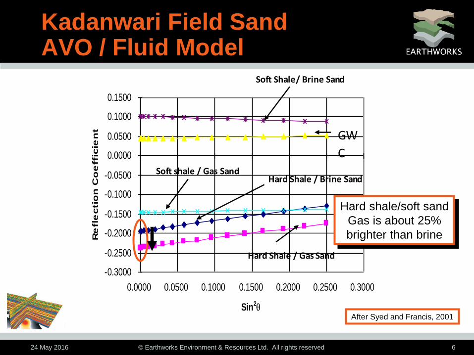
Kadanwari Field Sand AVO / Fluid Model
-0.3000
-0.2500
-0.2000
-0.1500
-0.1000
-0.0500
0.0000
0.0500
0.1000
0.1500
0.0000 0.0500 0.1000 0.1500 0.2000 0.2500 0.3000
Sin2q
Re
fle
ctio
n C
oe
ffic
ien
t
GW
C
Hard Shale / Gas Sand
Hard Shale / Brine Sand Soft shale / Gas Sand
Soft Shale/ Brine Sand
Hard shale/soft sand
Gas is about 25%
brighter than brine
After Syed and Francis, 2001
24 May 2016 © Earthworks Environment & Resources Ltd. All rights reserved 7
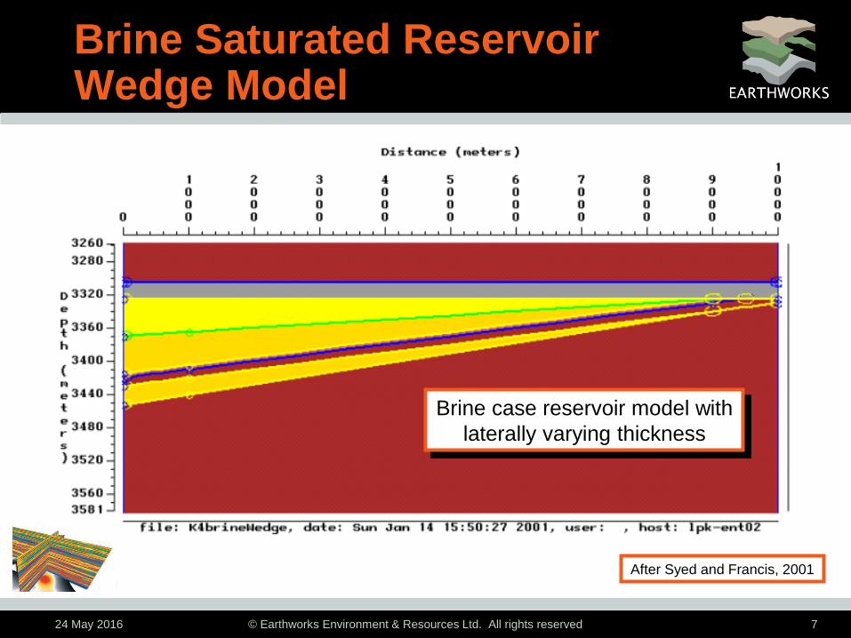
Brine Saturated Reservoir Wedge Model
Brine case reservoir model with
laterally varying thickness
After Syed and Francis, 2001

24 May 2016 © Earthworks Environment & Resources Ltd. All rights reserved 8
Brine Saturated Reservoir Relative Impedance Response
After Syed and Francis, 2001

24 May 2016 © Earthworks Environment & Resources Ltd. All rights reserved 9
Relative Impedance Amplitude Response with TWT Thickness
0
0.2
0.4
0.6
0.8
1
1.2
1.4
0 5 10 15 20 25 30 35
Re
lati
ve A
mp
litu
de
TWT (ms)
Reference Amplitude = 0.7
After Syed and Francis, 2001
24 May 2016 © Earthworks Environment & Resources Ltd. All rights reserved 10
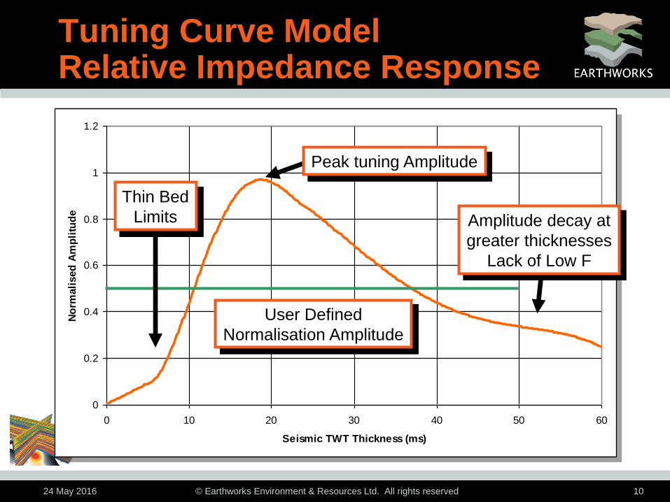
Tuning Curve Model Relative Impedance Response
0
0.2
0.4
0.6
0.8
1
1.2
0 10 20 30 40 50 60
Seismic TWT Thickness (ms)
No
rmali
sed
Am
pli
tud
e
Peak tuning Amplitude
Amplitude decay at
greater thicknesses
Lack of Low F
User Defined
Normalisation Amplitude
Thin Bed
Limits

24 May 2016 © Earthworks Environment & Resources Ltd. All rights reserved 11
Overview of Connolly (2007)
• Connolly (2007) published a method of estimating
seismic net pay from seismic amplitude maps
– Extract thickness and amplitude between zero crossings
from relative impedance (coloured inversion) data
• Estimate Seismic Net Pay by simultaneously:
– Detune the amplitude using a modelled tuning curve
– Calculate apparent seismic Net-to-Gross
– Calculate apparent absolute time or z thickness of net sand

24 May 2016 © Earthworks Environment & Resources Ltd. All rights reserved 12
Amplitude Relation to N:G Different Time Thickness
0
0.2
0.4
0.6
0.8
1
1.2
0 10 20 30 40 50 60
Seismic TWT Thickness (ms)
No
rmali
sed
Am
pli
tud
e
Sand 2 Sand 1 Sand 3
Amplitude
N:G=0.48 N:G=0.41
N:G=0.91
The same amplitude corresponds
to very different N:G at different
thicknesses on the tuning curve

24 May 2016 © Earthworks Environment & Resources Ltd. All rights reserved 13
Seismic Net Pay or Detuning
• Connolly (2007) is constructed as a direct means of
calculating Seismic Net Pay and simultaneously
deals with both reservoir net/quality and detuning
• Excellent and elegant methodology but…
– Requires picking seismic zero crossings – time consuming
– 2D extracted thickness and amplitude maps only
– Requires well calibration
• There is considerable value in being able to rapidly
generate thickness/tuning corrected amplitudes
• Amplitude detuning only is a completely self-
consistent calculation that does not require wells

24 May 2016 © Earthworks Environment & Resources Ltd. All rights reserved 14
3D Seismic Detuning Earthworks DT-AMP™
• Earthworks has developed a method of removing
thickness related tuning effects from 3D seismic data
– Novel method developed over 2½ years with multiple client
trials in different geological environments
• DT-AMP detunes the 3D seismic trace volume in situ
• DT-AMP outputs significantly speed up amplitude
mapping and prospect generation from 3D seismic
• DT-AMP can extract and fit tuning curves from
windows or slices, without any horizon picking
– Significantly speeds up de-tuning analysis

24 May 2016 © Earthworks Environment & Resources Ltd. All rights reserved 15
Comments on Tuning Curves
• Tuning curves are independent of absolute
amplitude and so do not require well calibration
• Tuning curves are bandwidth dependent
– Very sensitive to low frequencies
• Tuning curves can vary both spatially and temporally
– Need to be able to generate in time window or slice
• There is a lot of valuable information in a tuning
curve
– Can be enhanced by plotting additional attributes
– Strat classes

24 May 2016 © Earthworks Environment & Resources Ltd. All rights reserved 16
High Frequency Response
Thickness
(seconds)
No
rma
lis
ed
tu
nin
g
cu
rve
Filter varying 5 – 30 Hz up to 5 – 77 Hz

24 May 2016 © Earthworks Environment & Resources Ltd. All rights reserved 17
Low Frequency Response
Thickness
(seconds)
No
rma
lis
ed
tu
nin
g
cu
rve
20 – 80 Hz
1 – 80 Hz

24 May 2016 © Earthworks Environment & Resources Ltd. All rights reserved 18
Sea Lion Field, Main Fan Original Coloured Inversion
Thinner Sand
Lower N:G
Thick Sand
High N:G
Bright Constant
Amplitudes Downdip
Well 14/10-4 Well 14/10-5
2100
2400
TW
T (
ms)

24 May 2016 © Earthworks Environment & Resources Ltd. All rights reserved 19
Sea Lion Field, Main Fan Detuned Modulated Amplitude
After Detuning, Downdip
Amplitudes Show N:G Change
Well 14/10-4 Well 14/10-5
2100
2400
TW
T (
ms)

24 May 2016 © Earthworks Environment & Resources Ltd. All rights reserved 20
0
1000
2000
3000
4000
5000
6000
7000
8000
0 10 20 30 40 50 60
Seis
mic
Am
plit
ud
e
Time Thickness (ms)
Before Detuning
N:G=70%
N:G=94%
Well 4 Well 5
Before Detuning:
Downdip Well 4 Higher Amplitude
But Lower Net:Gross

24 May 2016 © Earthworks Environment & Resources Ltd. All rights reserved 21
0
1000
2000
3000
4000
5000
6000
7000
8000
0 10 20 30 40 50 60
Seis
mic
Am
plit
ud
e
Time Thickness (ms)
After Detuning
N:G=70%
N:G=94%
Well 4 Well 5
Normalised Amplitude
After Detuning:
Downdip Well 4 Lower Amplitude
Consistent with Lower Net:Gross

24 May 2016 © Earthworks Environment & Resources Ltd. All rights reserved 22
3D Seismic Detuning Advantages to Interpreter
• Seismic sections from detuned output relate to
geology and property changes with the amplitude
effect due to thickness changes removed
– Rock property relations with amplitude will not be generally
valid without removing tuning effects

24 May 2016 © Earthworks Environment & Resources Ltd. All rights reserved 23
Sea Lion Field, Beverley Fan Time Thickness Map
From Francis et al, 2015

24 May 2016 © Earthworks Environment & Resources Ltd. All rights reserved 24
Sea Lion Field, Beverley Fan EEI -70 Amplitude
High amplitudes due
to thickness tuning
From Francis et al, 2015

24 May 2016 © Earthworks Environment & Resources Ltd. All rights reserved 25
Sea Lion Field, Beverley Fan Detuned Net Sand
Genuine Sweet Spots
Revealed by detuning
From Francis et al, 2015

24 May 2016 © Earthworks Environment & Resources Ltd. All rights reserved 26
3D Seismic Detuning Advantages to Interpreter
• Fast and reliable interpretation of amplitude
anomalies
– Sea Lion Field multiple turbidite fans took over 6 weeks to
pick manually and extract 2D grids
– Single event picking on 3D detuned output reduces picking
and analysis time to just a day or so per fan
• Same single event pick can be used to display
horizon slices of amplitude, detuned amplitude,
thickness, seismic net pay and other new and novel
attributes that arise from an analysis of tuning
responses on seismic
– Currently unpublished

24 May 2016 © Earthworks Environment & Resources Ltd. All rights reserved 27
Central North Sea Rotliegendes Sandstone
Original

24 May 2016 © Earthworks Environment & Resources Ltd. All rights reserved 28
Central North Sea Rotliegendes Sandstone
Detuned

24 May 2016 © Earthworks Environment & Resources Ltd. All rights reserved 29
Central North Sea Rotliegendes SSt Detuning
• After detuning the field outline is much more sharply
defined, with better closure separation to the NE
• The amplitude interpretation is different after
detuning:
– Bright events in north are either removed/de-emphasised or
in different locations
– Amplitudes to south are normalised and are now consistent
with known presence of Rotliegendes in well penetrations
– Interesting bright area in south revealed after detuning

24 May 2016 © Earthworks Environment & Resources Ltd. All rights reserved 30
York & Greater York DT-AMP™ Detuning Study
• The York Field and the Greater York Area
– UKCS southern gas basin gas fields and targets
• Gas in Rotliegendes and Carboniferous reservoirs
– Presence of gas is expected to brighten seismic amplitudes
• DT-AMP detuning was applied to the seismic and
automated, entirely self-consistent attributes were
extracted from a single existing interpretation pick
– TT0X TWT thickness of interval
– Top (and base) TWT of interval times
– Amplitude and detuned amplitude maps

24 May 2016 © Earthworks Environment & Resources Ltd. All rights reserved 31
Top Rotliegend TTOP (ms)
York
Rough

24 May 2016 © Earthworks Environment & Resources Ltd. All rights reserved 32
Rotliegendes TWT Thickness TT0X (ms)
York
Rough

24 May 2016 © Earthworks Environment & Resources Ltd. All rights reserved 33
Rotliegendes Original Amplitude Map
York
Rough

24 May 2016 © Earthworks Environment & Resources Ltd. All rights reserved 34
Rotliegendes DT-AMP™ Detuned Amplitudes
York
Rough

24 May 2016 © Earthworks Environment & Resources Ltd. All rights reserved 35
Rotliegendes Original Amplitude Map
Relative Amplitude Scaling

24 May 2016 © Earthworks Environment & Resources Ltd. All rights reserved 36
Rotliegendes DT-AMP™ Detuned Amplitudes
Relative Amplitude Scaling

24 May 2016 © Earthworks Environment & Resources Ltd. All rights reserved 37
York & Greater York
• The significance of detuning seismic amplitudes is
clearly demonstrated by the before and after
amplitude maps
• Thickness related tuning is by far the predominant
effect on seismic amplitudes
– Without detuning, amplitude interpretation is misleading
• Detuning significantly improves amplitude continuity
– Small thickness changes result in large amplitude changes
• After the detuning study, the Greater York acreage
was relinquished by all partners

24 May 2016 © Earthworks Environment & Resources Ltd. All rights reserved 38
Seismic Detuning Summary
• The largest physical effect controlling seismic
amplitude variation is thickness change
• Thickness related tuning can double seismic
amplitudes
• All seismic amplitudes should be detuned before use
• Amplitude detuning is a completely self-consistent
calculation and does not require well control
• 3D Seismic detuning extends existing 2D map based
detuning to detune seismic trace amplitudes in situ
on a 3D (or 2D) relative impedance volume

24 May 2016 © Earthworks Environment & Resources Ltd. All rights reserved 39
DT-AMP™ 3D Seismic Detuning Summary
• 3D Seismic detuning
– Facilitates the comparison of the possible effects of tuning /
no tuning directly on 3D seismic sections
– Removes one risk factor in assessing amplitude data
– Makes amplitudes more easily interpreted in terms of
geology and property changes
– Significantly speeds up amplitude analysis
– Introduces additional constraining attributes
– Allows direct computation of tuning data without seismic
horizon interpretation or picking

24 May 2016 © Earthworks Environment & Resources Ltd. All rights reserved 40
Acknowledgements for Data
• Centrica PLC
• Rockhopper Exploration PLC
• Premier Oil
• Also older examples from
– LASMO
– Acorn Oil & Gas/Tuscan Energy (Scotland) Ltd
24 May 2016 © Earthworks Environment & Resources Ltd. All rights reserved 41
http://www.earthworks-reservoir.com