aluminum electrolytic capacitors - tdk europe · aluminum electrolytic capacitors snap-in...
TRANSCRIPT
Aluminum electrolytic capacitors
Snap-in capacitors
Series/Type: B43545
Date: A 2018
© EPCOS AG 2018. Reproduction, publication and dissemination of this publication, enclosures hereto and theinformation contained therein without EPCOS' prior express consent is prohibited.
EPCOS AG is a TDK Group Company.
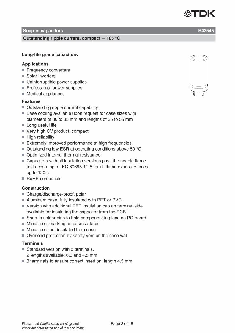
Long-life grade capacitors
ApplicationsFrequency convertersSolar invertersUninterruptible power suppliesProfessional power suppliesMedical appliances
FeaturesOutstanding ripple current capabilityBase cooling available upon request for case sizes withdiameters of 30 to 35 mm and lengths of 35 to 55 mmLong useful lifeVery high CV product, compactHigh reliabilityExtremely improved performance at high frequenciesOutstanding low ESR at operating conditions above 50 °COptimized internal thermal resistanceCapacitors with all insulation versions pass the needle flametest according to IEC 60695-11-5 for all flame exposure timesup to 120 sRoHS-compatible
ConstructionCharge/discharge-proof, polarAluminum case, fully insulated with PET or PVCVersion with additional PET insulation cap on terminal sideavailable for insulating the capacitor from the PCBSnap-in solder pins to hold component in place on PC-boardMinus pole marking on case surfaceMinus pole not insulated from caseOverload protection by safety vent on the case wall
TerminalsStandard version with 2 terminals,2 lengths available: 6.3 and 4.5 mm3 terminals to ensure correct insertion: length 4.5 mm
Snap-in capacitors B43545
Outstanding ripple current, compact 105 °C
Page 2 of 18Please read Cautions and warnings andImportant notes at the end of this document.
1) Refer to chapter "General technical information, 5 Useful life" on how to interpret useful life.
Specifications and characteristics in brief
Rated voltage VR 400 ... 500 V DC
Surge voltage VS 1.10 VR
Rated capacitance CR 68 ... 820 μF
Capacitance tolerance ±20% M
Dissipation factor tan δ(20 °C, 120 Hz)
VR = 400 V DC: tan δ ≤ 0.15VR ≥ 450 V DC: tan δ ≤ 0.20
Leakage current Ileak
(5 min, 20 °C)
Self-inductance ESL Approx. 20 nH
Useful life1) Requirements:
105 °C; VR; IAC,R > 5000 h ΔC/C ≤ 20% of initial value
tan δ ≤ 2 times initial specified limit
Ileak ≤ initial specified limit
Voltage endurance test Post test requirements:
105 °C; VR 2000 h ΔC/C ≤ 10% of initial value
tan δ ≤ 1.3 times initial specified limit
Ileak ≤ initial specified limit
Vibration resistancetest
To IEC 60068-2-6, test Fc:Frequency range 10 Hz ... 55 Hz, displacement amplitude 0.35 mm,acceleration max. 5 g, duration 3 × 2 h.Capacitor mounted by its body which is rigidly clamped to the worksurface.
Characteristics at lowtemperature
Max. impedanceratio at 100 Hz VR 400 V 450 V 500 V
Z -25 °C / Z 20 °C 3 5 7
Z -40 °C / Z 20 °C 7 10 20
IEC climatic category To IEC 60068-1:VR ≤ 450: 40/105/56 ( 40 °C/+105 °C/56 days damp heat test)VR = 500: 25/105/56 ( 25 °C/+105 °C/56 days damp heat test)The capacitors can be operated in the temperature range of 40 °C butthe impedance at 40 °C must be taken into consideration.
Sectional specification IEC 60384-4
B43545
Outstanding ripple current, compact 105 °C
Page 3 of 18Please read Cautions and warnings andImportant notes at the end of this document.
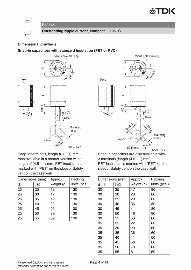
Dimensional drawings
Snap-in capacitors with standard insulation (PET or PVC)
Snap-in terminals, length (6.3 ±1) mm.Also available in a shorter version with alength of (4.5 1) mm. PET insulation ismarked with "PET" on the sleeve. Safetyvent on the case wall.
Snap-in capacitors are also available with3 terminals (length (4.5 1) mm).PET insulation is marked with "PET" on thesleeve. Safety vent on the case wall.
Dimensions (mm) Approx.weight (g)
Packingunits (pcs.)d +1 l ±2
25 25 13 13025 30 17 13025 35 19 13025 40 22 13025 45 25 13025 50 29 13025 55 32 130
Dimensions (mm) Approx.weight (g)
Packingunits (pcs.)d +1 l ±2
30 25 17 8030 30 23 8030 35 29 8030 40 36 8030 45 41 8030 50 46 8030 55 53 8035 25 22 6035 30 29 6035 35 36 6035 40 41 6035 45 56 6035 50 70 6035 55 81 60
B43545
Outstanding ripple current, compact 105 °C
Page 4 of 18Please read Cautions and warnings andImportant notes at the end of this document.
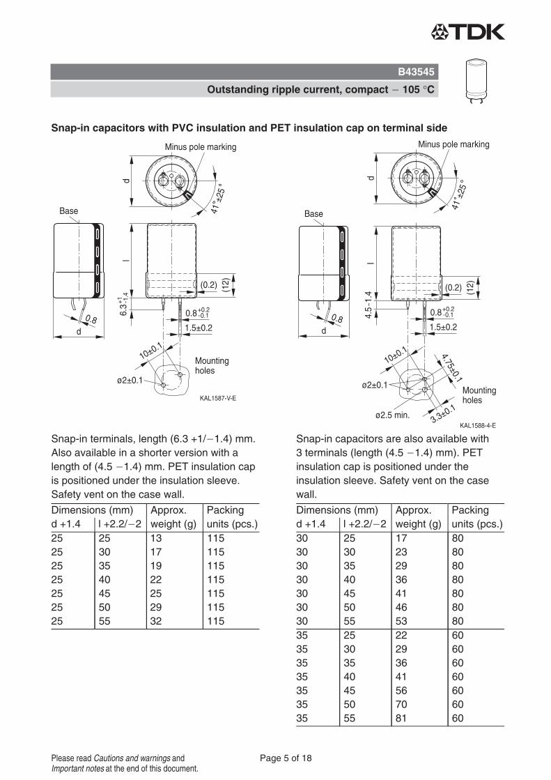
Snap-in capacitors with PVC insulation and PET insulation cap on terminal side
Snap-in terminals, length (6.3 +1/ 1.4) mm.Also available in a shorter version with alength of (4.5 1.4) mm. PET insulation capis positioned under the insulation sleeve.Safety vent on the case wall.
Snap-in capacitors are also available with3 terminals (length (4.5 1.4) mm). PETinsulation cap is positioned under theinsulation sleeve. Safety vent on the casewall.
Dimensions (mm) Approx.weight (g)
Packingunits (pcs.)d +1.4 l +2.2/ 2
25 25 13 11525 30 17 11525 35 19 11525 40 22 11525 45 25 11525 50 29 11525 55 32 115
Dimensions (mm) Approx.weight (g)
Packingunits (pcs.)d +1.4 l +2.2/ 2
30 25 17 8030 30 23 8030 35 29 8030 40 36 8030 45 41 8030 50 46 8030 55 53 8035 25 22 6035 30 29 6035 35 36 6035 40 41 6035 45 56 6035 50 70 6035 55 81 60
B43545
Outstanding ripple current, compact 105 °C
Page 5 of 18Please read Cautions and warnings andImportant notes at the end of this document.
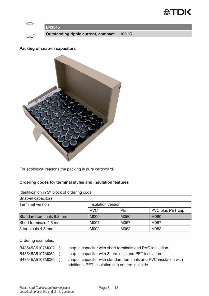
Packing of snap-in capacitors
For ecological reasons the packing is pure cardboard.
Ordering codes for terminal styles and insulation features
Identification in 3rd block of ordering code
Snap-in capacitors
Terminal version Insulation version
PVC PET PVC plus PET cap
Standard terminals 6.3 mm M000 M060 M080
Short terminals 4.5 mm M007 M067 M087
3 terminals 4.5 mm M002 M062 M082
Ordering examples:
B43545A5107M007 } snap-in capacitor with short terminals and PVC insulation
B43545A5107M062 } snap-in capacitor with 3 terminals and PET insulation
B43545A5107M080 } snap-in capacitor with standard terminals and PVC insulation withadditional PET insulation cap on terminal side
B43545
Outstanding ripple current, compact 105 °C
Page 6 of 18Please read Cautions and warnings andImportant notes at the end of this document.
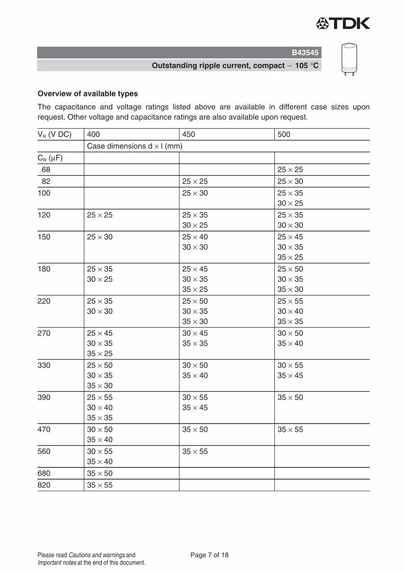
Overview of available types
The capacitance and voltage ratings listed above are available in different case sizes uponrequest. Other voltage and capacitance ratings are also available upon request.
VR (V DC) 400 450 500
Case dimensions d × l (mm)
CR (μF)
68 25 × 25
82 25 × 25 25 × 30
100 25 × 30 25 × 3530 × 25
120 25 × 25 25 × 3530 × 25
25 × 3530 × 30
150 25 × 30 25 × 4030 × 30
25 × 4530 × 3535 × 25
180 25 × 3530 × 25
25 × 4530 × 3535 × 25
25 × 5030 × 3535 × 30
220 25 × 3530 × 30
25 × 5030 × 3535 × 30
25 × 5530 × 4035 × 35
270 25 × 4530 × 3535 × 25
30 × 4535 × 35
30 × 5035 × 40
330 25 × 5030 × 3535 × 30
30 × 5035 × 40
30 × 5535 × 45
390 25 × 5530 × 4035 × 35
30 × 5535 × 45
35 × 50
470 30 × 5035 × 40
35 × 50 35 × 55
560 30 × 5535 × 40
35 × 55
680 35 × 50
820 35 × 55
B43545
Outstanding ripple current, compact 105 °C
Page 7 of 18Please read Cautions and warnings andImportant notes at the end of this document.
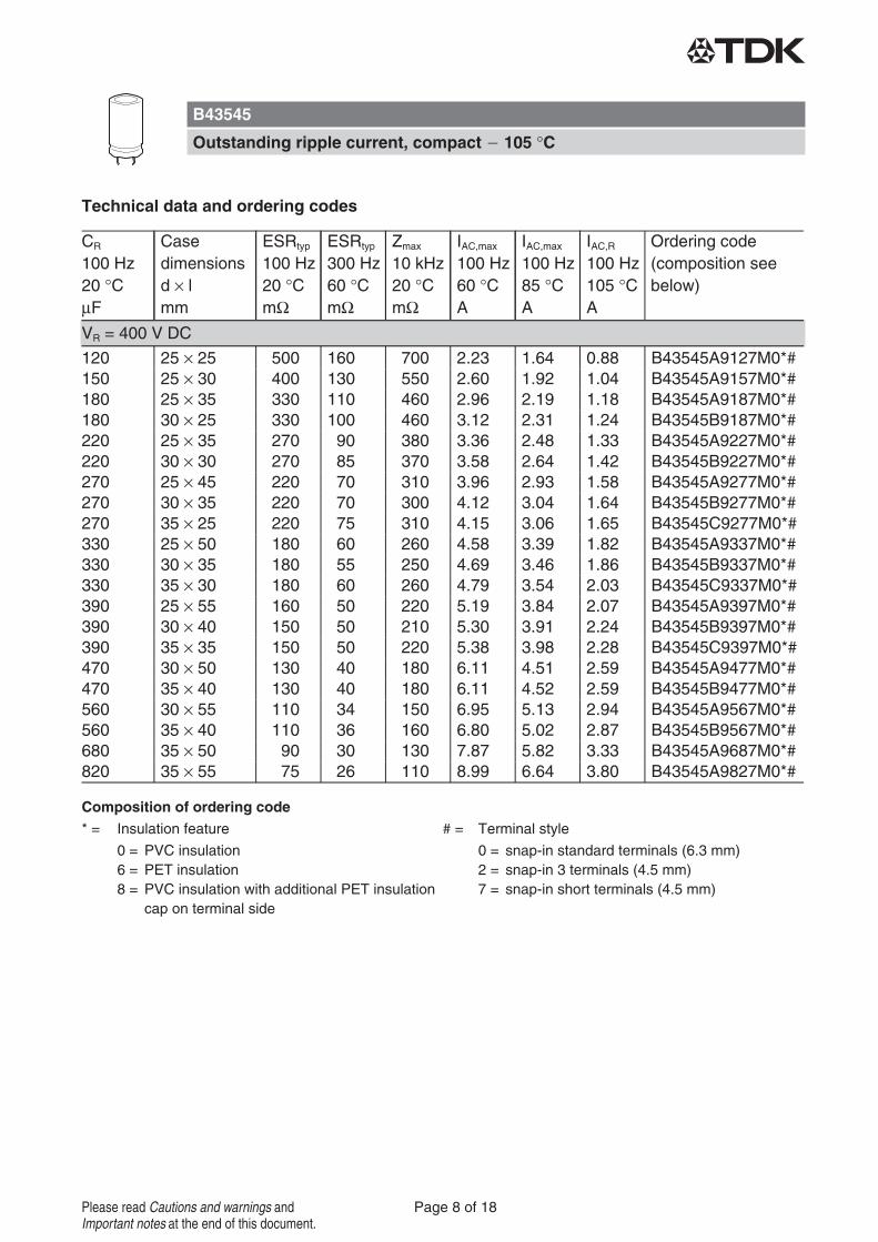
Technical data and ordering codes
CR
100 Hz20 °CμF
Casedimensionsd × lmm
ESRtyp
100 Hz20 °CmΩ
ESRtyp
300 Hz60 °CmΩ
Zmax
10 kHz20 °CmΩ
IAC,max
100 Hz60 °CA
IAC,max
100 Hz85 °CA
IAC,R
100 Hz105 °CA
Ordering code(composition seebelow)
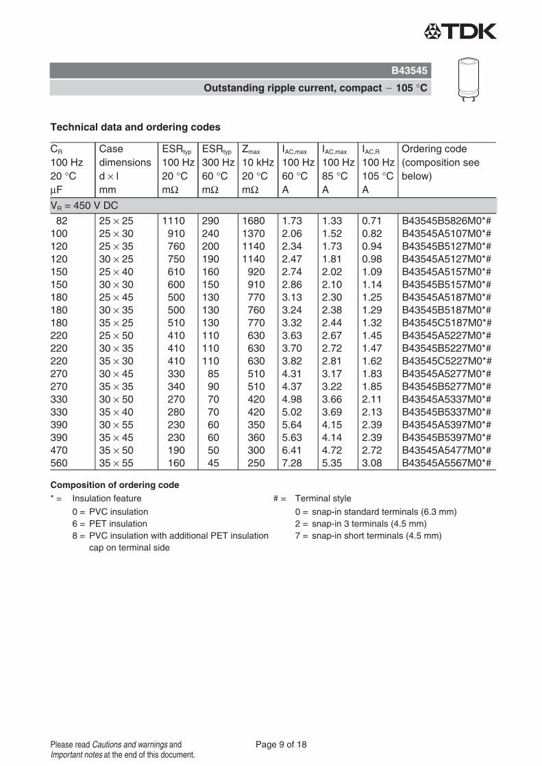
Composition of ordering code* = Insulation feature # = Terminal style
0 = PVC insulation6 = PET insulation8 = PVC insulation with additional PET insulation
cap on terminal side
0 = snap-in standard terminals (6.3 mm)2 = snap-in 3 terminals (4.5 mm)7 = snap-in short terminals (4.5 mm)
VR = 400 V DC
120 25 × 25 500 160 700 2.23 1.64 0.88 B43545A9127M0*#150 25 × 30 400 130 550 2.60 1.92 1.04 B43545A9157M0*#180 25 × 35 330 110 460 2.96 2.19 1.18 B43545A9187M0*#180 30 × 25 330 100 460 3.12 2.31 1.24 B43545B9187M0*#220 25 × 35 270 90 380 3.36 2.48 1.33 B43545A9227M0*#220 30 × 30 270 85 370 3.58 2.64 1.42 B43545B9227M0*#270 25 × 45 220 70 310 3.96 2.93 1.58 B43545A9277M0*#270 30 × 35 220 70 300 4.12 3.04 1.64 B43545B9277M0*#270 35 × 25 220 75 310 4.15 3.06 1.65 B43545C9277M0*#330 25 × 50 180 60 260 4.58 3.39 1.82 B43545A9337M0*#330 30 × 35 180 55 250 4.69 3.46 1.86 B43545B9337M0*#330 35 × 30 180 60 260 4.79 3.54 2.03 B43545C9337M0*#390 25 × 55 160 50 220 5.19 3.84 2.07 B43545A9397M0*#390 30 × 40 150 50 210 5.30 3.91 2.24 B43545B9397M0*#390 35 × 35 150 50 220 5.38 3.98 2.28 B43545C9397M0*#470 30 × 50 130 40 180 6.11 4.51 2.59 B43545A9477M0*#470 35 × 40 130 40 180 6.11 4.52 2.59 B43545B9477M0*#560 30 × 55 110 34 150 6.95 5.13 2.94 B43545A9567M0*#560 35 × 40 110 36 160 6.80 5.02 2.87 B43545B9567M0*#680 35 × 50 90 30 130 7.87 5.82 3.33 B43545A9687M0*#820 35 × 55 75 26 110 8.99 6.64 3.80 B43545A9827M0*#
B43545
Outstanding ripple current, compact 105 °C
Page 8 of 18Please read Cautions and warnings andImportant notes at the end of this document.
Technical data and ordering codes
CR
100 Hz20 °CμF
Casedimensionsd × lmm
ESRtyp
100 Hz20 °CmΩ
ESRtyp
300 Hz60 °CmΩ
Zmax
10 kHz20 °CmΩ
IAC,max
100 Hz60 °CA
IAC,max
100 Hz85 °CA
IAC,R
100 Hz105 °CA
Ordering code(composition seebelow)
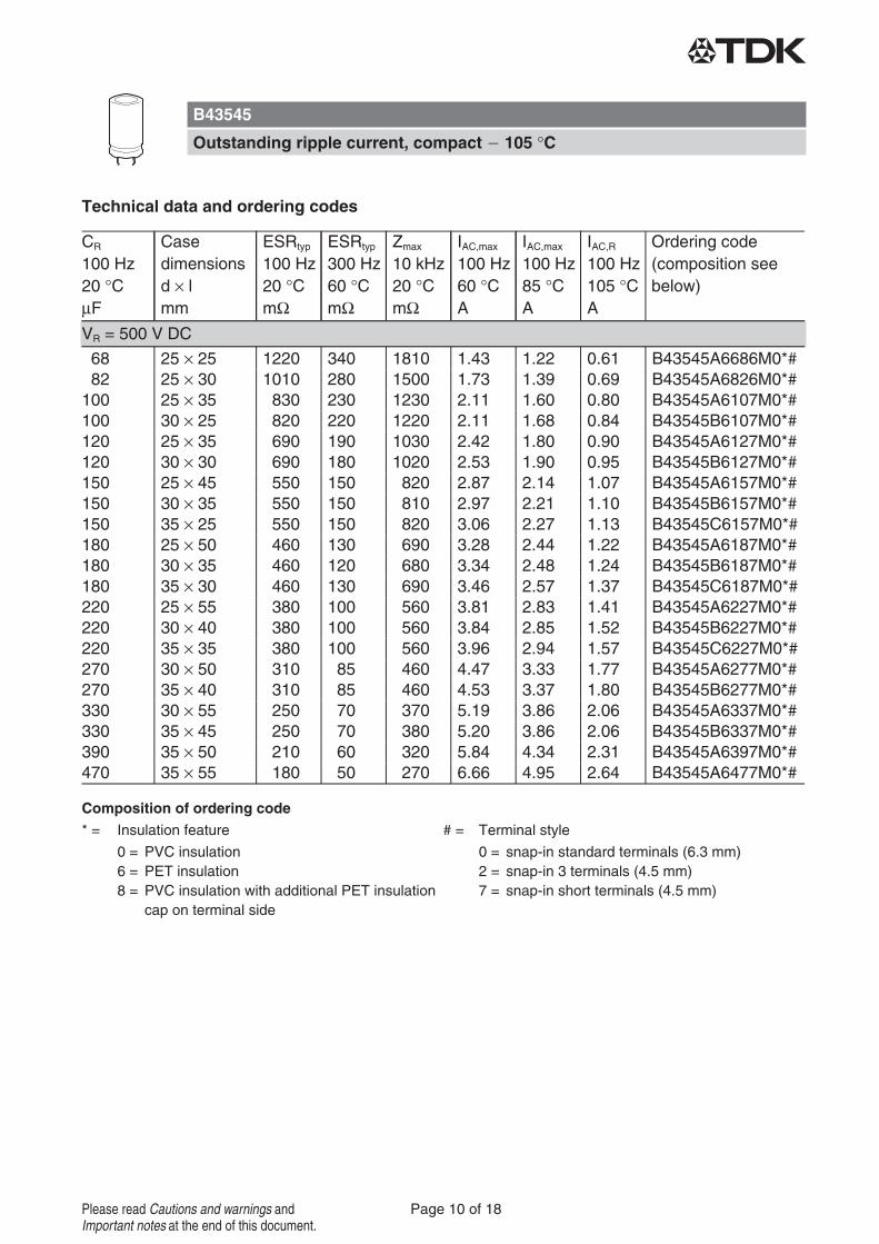
Composition of ordering code* = Insulation feature # = Terminal style
0 = PVC insulation6 = PET insulation8 = PVC insulation with additional PET insulation
cap on terminal side
0 = snap-in standard terminals (6.3 mm)2 = snap-in 3 terminals (4.5 mm)7 = snap-in short terminals (4.5 mm)
VR = 450 V DC
82 25 × 25 1110 290 1680 1.73 1.33 0.71 B43545B5826M0*#100 25 × 30 910 240 1370 2.06 1.52 0.82 B43545A5107M0*#120 25 × 35 760 200 1140 2.34 1.73 0.94 B43545B5127M0*#120 30 × 25 750 190 1140 2.47 1.81 0.98 B43545A5127M0*#150 25 × 40 610 160 920 2.74 2.02 1.09 B43545A5157M0*#150 30 × 30 600 150 910 2.86 2.10 1.14 B43545B5157M0*#180 25 × 45 500 130 770 3.13 2.30 1.25 B43545A5187M0*#180 30 × 35 500 130 760 3.24 2.38 1.29 B43545B5187M0*#180 35 × 25 510 130 770 3.32 2.44 1.32 B43545C5187M0*#220 25 × 50 410 110 630 3.63 2.67 1.45 B43545A5227M0*#220 30 × 35 410 110 630 3.70 2.72 1.47 B43545B5227M0*#220 35 × 30 410 110 630 3.82 2.81 1.62 B43545C5227M0*#270 30 × 45 330 85 510 4.31 3.17 1.83 B43545A5277M0*#270 35 × 35 340 90 510 4.37 3.22 1.85 B43545B5277M0*#330 30 × 50 270 70 420 4.98 3.66 2.11 B43545A5337M0*#330 35 × 40 280 70 420 5.02 3.69 2.13 B43545B5337M0*#390 30 × 55 230 60 350 5.64 4.15 2.39 B43545A5397M0*#390 35 × 45 230 60 360 5.63 4.14 2.39 B43545B5397M0*#470 35 × 50 190 50 300 6.41 4.72 2.72 B43545A5477M0*#560 35 × 55 160 45 250 7.28 5.35 3.08 B43545A5567M0*#
B43545
Outstanding ripple current, compact 105 °C
Page 9 of 18Please read Cautions and warnings andImportant notes at the end of this document.
Technical data and ordering codes
CR
100 Hz20 °CμF
Casedimensionsd × lmm
ESRtyp
100 Hz20 °CmΩ
ESRtyp
300 Hz60 °CmΩ
Zmax
10 kHz20 °CmΩ
IAC,max
100 Hz60 °CA
IAC,max
100 Hz85 °CA
IAC,R
100 Hz105 °CA
Ordering code(composition seebelow)
Composition of ordering code* = Insulation feature # = Terminal style
0 = PVC insulation6 = PET insulation8 = PVC insulation with additional PET insulation
cap on terminal side
0 = snap-in standard terminals (6.3 mm)2 = snap-in 3 terminals (4.5 mm)7 = snap-in short terminals (4.5 mm)
VR = 500 V DC
68 25 × 25 1220 340 1810 1.43 1.22 0.61 B43545A6686M0*#82 25 × 30 1010 280 1500 1.73 1.39 0.69 B43545A6826M0*#
100 25 × 35 830 230 1230 2.11 1.60 0.80 B43545A6107M0*#100 30 × 25 820 220 1220 2.11 1.68 0.84 B43545B6107M0*#120 25 × 35 690 190 1030 2.42 1.80 0.90 B43545A6127M0*#120 30 × 30 690 180 1020 2.53 1.90 0.95 B43545B6127M0*#150 25 × 45 550 150 820 2.87 2.14 1.07 B43545A6157M0*#150 30 × 35 550 150 810 2.97 2.21 1.10 B43545B6157M0*#150 35 × 25 550 150 820 3.06 2.27 1.13 B43545C6157M0*#180 25 × 50 460 130 690 3.28 2.44 1.22 B43545A6187M0*#180 30 × 35 460 120 680 3.34 2.48 1.24 B43545B6187M0*#180 35 × 30 460 130 690 3.46 2.57 1.37 B43545C6187M0*#220 25 × 55 380 100 560 3.81 2.83 1.41 B43545A6227M0*#220 30 × 40 380 100 560 3.84 2.85 1.52 B43545B6227M0*#220 35 × 35 380 100 560 3.96 2.94 1.57 B43545C6227M0*#270 30 × 50 310 85 460 4.47 3.33 1.77 B43545A6277M0*#270 35 × 40 310 85 460 4.53 3.37 1.80 B43545B6277M0*#330 30 × 55 250 70 370 5.19 3.86 2.06 B43545A6337M0*#330 35 × 45 250 70 380 5.20 3.86 2.06 B43545B6337M0*#390 35 × 50 210 60 320 5.84 4.34 2.31 B43545A6397M0*#470 35 × 55 180 50 270 6.66 4.95 2.64 B43545A6477M0*#
B43545
Outstanding ripple current, compact 105 °C
Page 10 of 18Please read Cautions and warnings andImportant notes at the end of this document.
1) Refer to chapter "General technical information, 5 Useful life" on how to interpret useful life.
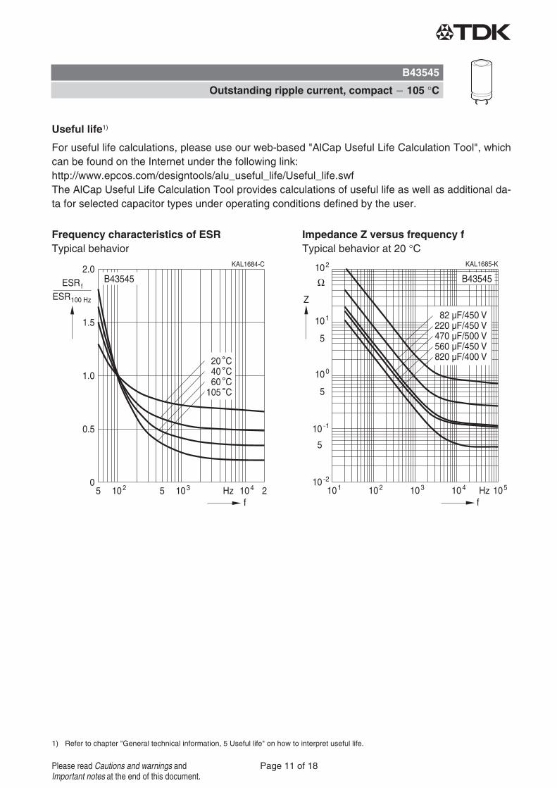
Useful life1)
For useful life calculations, please use our web-based "AlCap Useful Life Calculation Tool", whichcan be found on the Internet under the following link:http://www.epcos.com/designtools/alu_useful_life/Useful_life.swfThe AlCap Useful Life Calculation Tool provides calculations of useful life as well as additional da-ta for selected capacitor types under operating conditions defined by the user.
Frequency characteristics of ESRTypical behavior
Impedance Z versus frequency fTypical behavior at 20 °C
B43545
Outstanding ripple current, compact 105 °C
Page 11 of 18Please read Cautions and warnings andImportant notes at the end of this document.

Cautions and warnings
Personal safety
The electrolytes used by EPCOS have been optimized both with a view to the intendedapplication and with regard to health and environmental compatibility. They do not contain anysolvents that are detrimental to health, e.g. dimethyl formamide (DMF) or dimethyl acetamide(DMAC).Furthermore, some of the high-voltage electrolytes used by EPCOS are self-extinguishing.
As far as possible, EPCOS does not use any dangerous chemicals or compounds to produceoperating electrolytes, although in exceptional cases, such materials must be used in order toachieve specific physical and electrical properties because no alternative materials are currentlyknown. We do, however, restrict the amount of dangerous materials used in our products to anabsolute minimum.
Materials and chemicals used in EPCOS aluminum electrolytic capacitors are continuouslyadapted in compliance with the EPCOS Corporate Environmental Policy and the latestEU regulations and guidelines such as RoHS, REACH/SVHC, GADSL, and ELV.
MDS (Material Data Sheets) are available on the EPCOS website for all types listed in the databook. MDS for customer specific capacitors are available upon request.MSDS (Material Safety Data Sheets) are available for all of our electrolytes upon request.
Nevertheless, the following rules should be observed when handling aluminum electrolyticcapacitors: No electrolyte should come into contact with eyes or skin. If electrolyte does comeinto contact with the skin, wash the affected areas immediately with running water. If the eyesare affected, rinse them for 10 minutes with plenty of water. If symptoms persist, seek medicaltreatment. Avoid inhaling electrolyte vapor or mists. Workplaces and other affected areas shouldbe well ventilated. Clothing that has been contaminated by electrolyte must be changed andrinsed in water.
B43545
Outstanding ripple current, compact 105 °C
Page 12 of 18Please read Cautions and warnings andImportant notes at the end of this document.
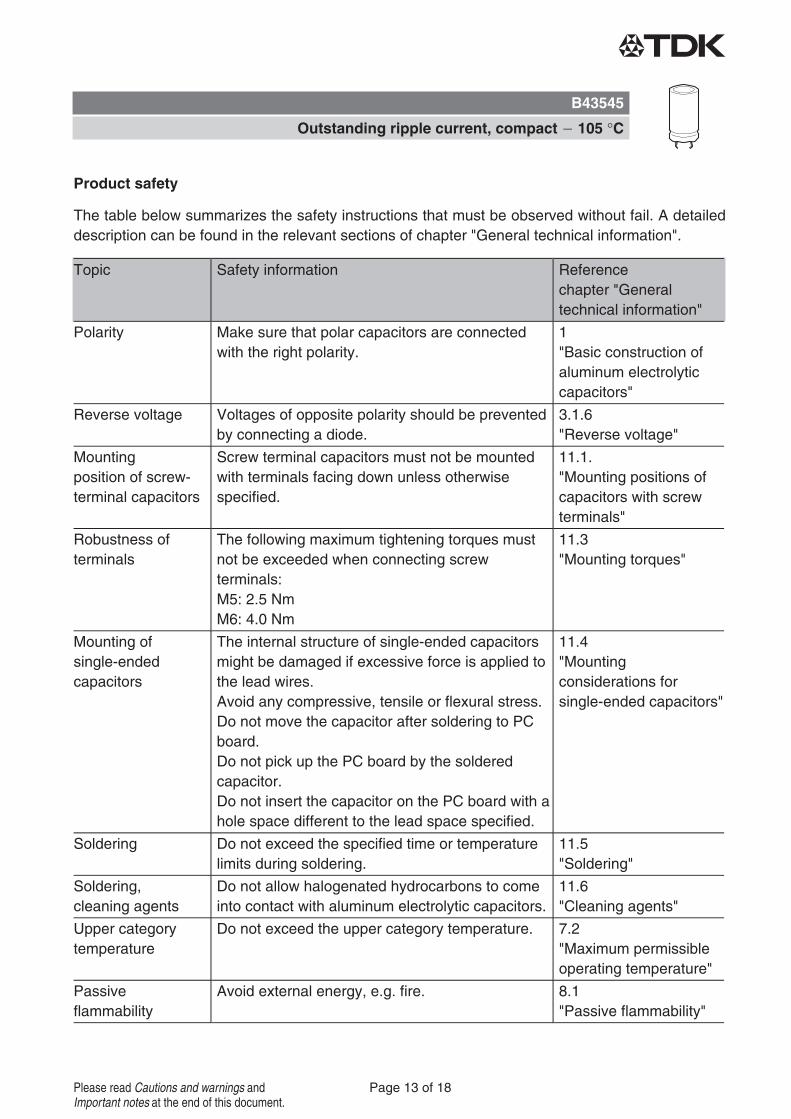
Product safety
The table below summarizes the safety instructions that must be observed without fail. A detaileddescription can be found in the relevant sections of chapter "General technical information".
Topic Safety information Referencechapter "Generaltechnical information"
Polarity Make sure that polar capacitors are connectedwith the right polarity.
1"Basic construction ofaluminum electrolyticcapacitors"
Reverse voltage Voltages of opposite polarity should be preventedby connecting a diode.
3.1.6"Reverse voltage"
Mountingposition of screw-terminal capacitors
Screw terminal capacitors must not be mountedwith terminals facing down unless otherwisespecified.
11.1."Mounting positions ofcapacitors with screwterminals"
Robustness ofterminals
The following maximum tightening torques mustnot be exceeded when connecting screwterminals:M5: 2.5 NmM6: 4.0 Nm
11.3"Mounting torques"
Mounting ofsingle-endedcapacitors
The internal structure of single-ended capacitorsmight be damaged if excessive force is applied tothe lead wires.Avoid any compressive, tensile or flexural stress.Do not move the capacitor after soldering to PCboard.Do not pick up the PC board by the solderedcapacitor.Do not insert the capacitor on the PC board with ahole space different to the lead space specified.
11.4"Mountingconsiderations forsingle-ended capacitors"
Soldering Do not exceed the specified time or temperaturelimits during soldering.
11.5"Soldering"
Soldering,cleaning agents
Do not allow halogenated hydrocarbons to comeinto contact with aluminum electrolytic capacitors.
11.6"Cleaning agents"
Upper categorytemperature
Do not exceed the upper category temperature. 7.2"Maximum permissibleoperating temperature"
Passiveflammability
Avoid external energy, e.g. fire. 8.1"Passive flammability"
B43545
Outstanding ripple current, compact 105 °C
Page 13 of 18Please read Cautions and warnings andImportant notes at the end of this document.
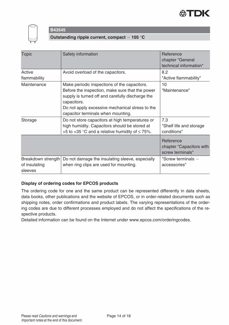
Topic Safety information Referencechapter "Generaltechnical information"
Activeflammability
Avoid overload of the capacitors. 8.2"Active flammability"
Maintenance Make periodic inspections of the capacitors.Before the inspection, make sure that the powersupply is turned off and carefully discharge thecapacitors.Do not apply excessive mechanical stress to thecapacitor terminals when mounting.
10"Maintenance"
Storage Do not store capacitors at high temperatures orhigh humidity. Capacitors should be stored at+5 to +35 °C and a relative humidity of ≤ 75%.
7.3"Shelf life and storageconditions"
Referencechapter "Capacitors withscrew terminals"
Breakdown strengthof insulatingsleeves
Do not damage the insulating sleeve, especiallywhen ring clips are used for mounting.
"Screw terminalsaccessories"
Display of ordering codes for EPCOS products
The ordering code for one and the same product can be represented differently in data sheets,data books, other publications and the website of EPCOS, or in order-related documents such asshipping notes, order confirmations and product labels. The varying representations of the order-ing codes are due to different processes employed and do not affect the specifications of the re-spective products.Detailed information can be found on the Internet under www.epcos.com/orderingcodes.
B43545
Outstanding ripple current, compact 105 °C
Page 14 of 18Please read Cautions and warnings andImportant notes at the end of this document.
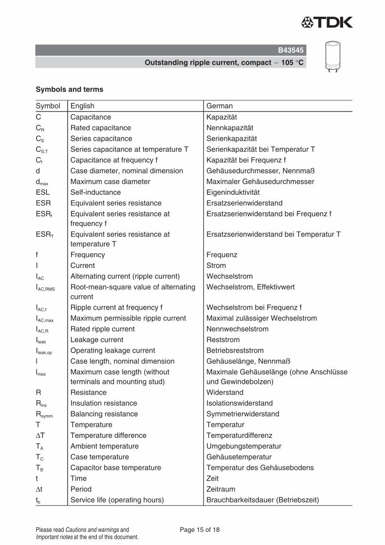
Symbols and terms
Symbol English German
C Capacitance Kapazität
CR Rated capacitance Nennkapazität
CS Series capacitance Serienkapazität
CS,T Series capacitance at temperature T Serienkapazität bei Temperatur T
Cf Capacitance at frequency f Kapazität bei Frequenz f
d Case diameter, nominal dimension Gehäusedurchmesser, Nennmaß
dmax Maximum case diameter Maximaler Gehäusedurchmesser
ESL Self-inductance Eigeninduktivität
ESR Equivalent series resistance Ersatzserienwiderstand
ESRf Equivalent series resistance atfrequency f
Ersatzserienwiderstand bei Frequenz f
ESRT Equivalent series resistance attemperature T
Ersatzserienwiderstand bei Temperatur T
f Frequency Frequenz
I Current Strom
IAC Alternating current (ripple current) Wechselstrom
IAC,RMS Root-mean-square value of alternatingcurrent
Wechselstrom, Effektivwert
IAC,f Ripple current at frequency f Wechselstrom bei Frequenz f
IAC,max Maximum permissible ripple current Maximal zulässiger Wechselstrom
IAC,R Rated ripple current Nennwechselstrom
Ileak Leakage current Reststrom
Ileak,op Operating leakage current Betriebsreststrom
l Case length, nominal dimension Gehäuselänge, Nennmaß
lmax Maximum case length (withoutterminals and mounting stud)
Maximale Gehäuselänge (ohne Anschlüsseund Gewindebolzen)
R Resistance Widerstand
Rins Insulation resistance Isolationswiderstand
Rsymm Balancing resistance Symmetrierwiderstand
T Temperature Temperatur
ΔT Temperature difference Temperaturdifferenz
TA Ambient temperature Umgebungstemperatur
TC Case temperature Gehäusetemperatur
TB Capacitor base temperature Temperatur des Gehäusebodens
t Time Zeit
Δt Period Zeitraum
tb Service life (operating hours) Brauchbarkeitsdauer (Betriebszeit)
B43545
Outstanding ripple current, compact 105 °C
Page 15 of 18Please read Cautions and warnings andImportant notes at the end of this document.
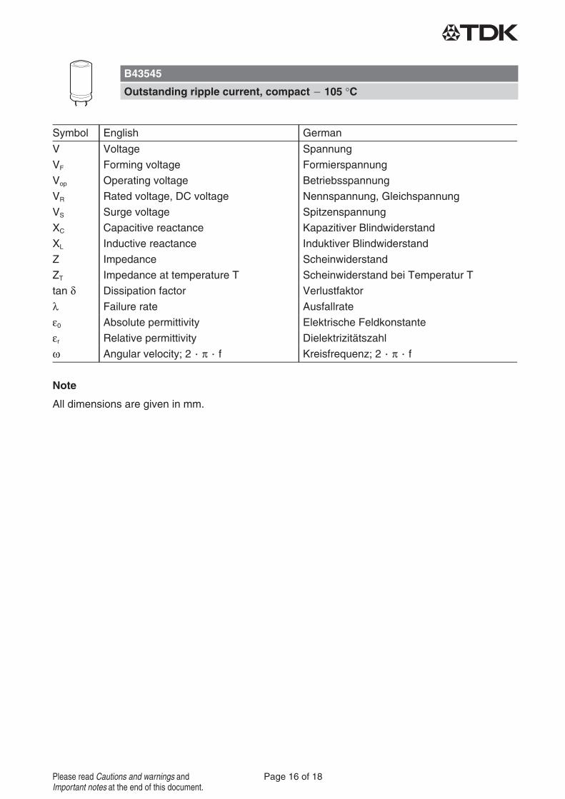
Symbol English German
V Voltage Spannung
VF Forming voltage Formierspannung
Vop Operating voltage Betriebsspannung
VR Rated voltage, DC voltage Nennspannung, Gleichspannung
VS Surge voltage Spitzenspannung
XC Capacitive reactance Kapazitiver Blindwiderstand
XL Inductive reactance Induktiver Blindwiderstand
Z Impedance Scheinwiderstand
ZT Impedance at temperature T Scheinwiderstand bei Temperatur T
tan δ Dissipation factor Verlustfaktor
λ Failure rate Ausfallrate
ε0 Absolute permittivity Elektrische Feldkonstante
εr Relative permittivity Dielektrizitätszahl
ω Angular velocity; 2 π f Kreisfrequenz; 2 π f
Note
All dimensions are given in mm.
B43545
Outstanding ripple current, compact 105 °C
Page 16 of 18Please read Cautions and warnings andImportant notes at the end of this document.
The following applies to all products named in this publication:1. Some parts of this publication contain statements about the suitability of our products for
certain areas of application. These statements are based on our knowledge of typical re-quirements that are often placed on our products in the areas of application concerned. Wenevertheless expressly point out that such statements cannot be regarded as bindingstatements about the suitability of our products for a particular customer application.As a rule, EPCOS is either unfamiliar with individual customer applications or less familiarwith them than the customers themselves. For these reasons, it is always ultimately incum-bent on the customer to check and decide whether an EPCOS product with the properties de-scribed in the product specification is suitable for use in a particular customer application.
2. We also point out that in individual cases, a malfunction of electronic components orfailure before the end of their usual service life cannot be completely ruled out in thecurrent state of the art, even if they are operated as specified. In customer applicationsrequiring a very high level of operational safety and especially in customer applications inwhich the malfunction or failure of an electronic component could endanger human life orhealth (e.g. in accident prevention or lifesaving systems), it must therefore be ensured bymeans of suitable design of the customer application or other action taken by the customer(e.g. installation of protective circuitry or redundancy) that no injury or damage is sustained bythird parties in the event of malfunction or failure of an electronic component.
3. The warnings, cautions and product-specific notes must be observed.4. In order to satisfy certain technical requirements, some of the products described in this
publication may contain substances subject to restrictions in certain jurisdictions (e.g.because they are classed as hazardous). Useful information on this will be found in our Ma-terial Data Sheets on the Internet (www.epcos.com/material). Should you have any more de-tailed questions, please contact our sales offices.
5. We constantly strive to improve our products. Consequently, the products described in thispublication may change from time to time. The same is true of the corresponding productspecifications. Please check therefore to what extent product descriptions and specificationscontained in this publication are still applicable before or when you place an order. We alsoreserve the right to discontinue production and delivery of products. Consequently, wecannot guarantee that all products named in this publication will always be available. Theaforementioned does not apply in the case of individual agreements deviating from the fore-going for customer-specific products.
6. Unless otherwise agreed in individual contracts, all orders are subject to the current ver-sion of the "General Terms of Delivery for Products and Services in the Electrical In-dustry" published by the German Electrical and Electronics Industry Association(ZVEI).
Important notes
Page 1 of 1

7. Our manufacturing sites serving the automotive business apply the IATF 16949standard. The IATF certifications confirm our compliance with requirements regarding thequality management system in the automotive industry. Referring to customer requirementsand customer specific requirements (“CSR”) TDK always has and will continue to have thepolicy of respecting individual agreements. Even if IATF 16949 may appear to support theacceptance of unilateral requirements, we hereby like to emphasize that only requirementsmutually agreed upon can and will be implemented in our Quality Management System.For clarification purposes we like to point out that obligations from IATF 16949 shall onlybecome legally binding if individually agreed upon.
8. The trade names EPCOS, CeraCharge, CeraDiode, CeraLink, CeraPad, CeraPlas, CSMP,CTVS, DeltaCap, DigiSiMic, ExoCore, FilterCap, FormFit, LeaXield, MiniBlue, MiniCell, MKD,MKK, MotorCap, PCC, PhaseCap, PhaseCube, PhaseMod, PhiCap, PowerHap, PQSine,PQvar, SIFERRIT, SIFI, SIKOREL, SilverCap, SIMDAD, SiMic, SIMID, SineFormer, SIOV,ThermoFuse, WindCap are trademarks registered or pending in Europe and in other coun-tries. Further information will be found on the Internet at www.epcos.com/trademarks.
Release 2018-06
Important notes
Page 1 of 1