aluminum electrolytic capacitors - capacitors with screw
TRANSCRIPT

Chipsmall Limited consists of a professional team with an average of over 10 year of expertise in the distribution
of electronic components. Based in Hongkong, we have already established firm and mutual-benefit business
relationships with customers from,Europe,America and south Asia,supplying obsolete and hard-to-find components
to meet their specific needs.
With the principle of “Quality Parts,Customers Priority,Honest Operation,and Considerate Service”,our business
mainly focus on the distribution of electronic components. Line cards we deal with include
Microchip,ALPS,ROHM,Xilinx,Pulse,ON,Everlight and Freescale. Main products comprise
IC,Modules,Potentiometer,IC Socket,Relay,Connector.Our parts cover such applications as commercial,industrial,
and automotives areas.
We are looking forward to setting up business relationship with you and hope to provide you with the best service
and solution. Let us make a better world for our industry!
Contact usTel: +86-755-8981 8866 Fax: +86-755-8427 6832
Email & Skype: [email protected] Web: www.chipsmall.com
Address: A1208, Overseas Decoration Building, #122 Zhenhua RD., Futian, Shenzhen, China

Aluminum electrolytic capacitors
Capacitors with screw terminals
Series/Type: B43713, B43733
Date: December 2016
© EPCOS AG 2016. Reproduction, publication and dissemination of this publication, enclosures hereto and theinformation contained therein without EPCOS' prior express consent is prohibited.
EPCOS AG is a TDK Group Company.

Long-life grade capacitors
Applications
Frequency converters
Wind power converters
Solar inverters
Professional power supplies
Uninterruptible power supplies
Features
High ripple current capability
Extra long useful life
High reliability
Extremely good electrical characteristics and small dimensions
All-welded construction ensures reliable electrical contact
PAPR terminals available (Protection Against Polarity Reversal)
Version available with an optimized base cooling design (heat
sink mounting) and featuring up to 2 times the ripple current
capability
Self-extinguishing electrolyte
RoHS-compatible
Construction
Charge-discharge proof, polar
Aluminum case, insulated with PVC sleeve
Version with PET insulation available upon request
Poles with screw terminal connections
Mounting with ring clips, clamps or threaded stud
Types with threaded stud are available with or without insulated
base
B43713 B43733
Capacitors with screw terminals B43713, B43733
Extra long useful life 85 °C
Page 2 of 25Please read Cautions and warnings and
Important notes at the end of this document.

1) Refer to chapter "General technical information, 5 Useful life" on how to interpret useful life.
Specifications and characteristics in brief
Rated voltage VR
Surge voltage VS
200 ... 500 V DC
1.15 VR (for VR ≤ 250 V DC)
1.10 VR (for VR ≥ 350 V DC)
Rated capacitance CR
Capacitance tolerance
820 ... 33000 µF
±20% M
Dissipation factor tan δ
(20 °C, 120 Hz)
≤ 0.20
Leakage current Ileak
(20 °C, 5 min)
Self-inductance ESL d = 51.6 mm: approx. 15 nH
d ≥ 64.3 mm: approx. 20 nH
Useful life1) 200 ... 450 V 500 V Requirements:
85 °C; VR; IAC,R > 15000 h > 12000 h ΔC/C ≤ 15% of initial value
tan δ ≤ 1.75 times initial specified limit
Ileak ≤ initial specified limit
Voltage endurance test Post test requirements:
85 °C; VR 2000 h ΔC/C ≤ 10% of initial value
tan δ ≤ 1.3 times initial specified limit
Ileak ≤ initial specified limit
Vibration resistance test To IEC 60068-2-6, test Fc:
Frequency range 10 ... 55 Hz, displacement amplitude 0.75 mm,
acceleration max. 10 g, duration 3 × 2 h.
Capacitor mounted by its body which is rigidly clamped to the work
surface.
Characteristics at low
temperature
Max. impedance
ratio at 100 Hz VR ≤ 250 V 350 V ≥ 400 V
Z -25°C / Z 20°C 5 4 4
Z -40°C / Z 20°C 21 20 16
IEC climatic category To IEC 60068-1:
25/085/56 ( 25 °C/+85 °C/56 days damp heat test)
The capacitors can be operated in the temperature range of
40 °C to +85 °C but the impedance at 40 °C must be taken into
consideration.
Detail specification
Sectional specification
Similar to CECC 30301-803, CECC 30301-807
IEC 60384-4
B43713, B43733
Extra long useful life 85 °C
Page 3 of 25Please read Cautions and warnings and
Important notes at the end of this document.

Ripple current capability
Due to the ripple current capability of the contact elements, the following current upper limits must
not be exceeded:
Capacitor diameter 51.6 mm 64.3 mm 76.9 mm 90 mm
IAC,max 34 A 57 A 74 A 89 A
Dimensional drawings
B43713
Ring clip/clamp mounting
B43733
Threaded stud mounting
For standard types with threaded stud the base is not insulated. Also refer to the mounting
instructions in chapter "Capacitors with screw terminals Accessories".
Screw terminals with UNF threads are available upon request.
B43713, B43733
Extra long useful life 85 °C
Page 4 of 25Please read Cautions and warnings and
Important notes at the end of this document.

Dimensions and weights (Standard capacitors, without heat sink)
Ter-
minal
Dimensions (mm) with insulating sleeve Approx.
weight (g)d l ±1 l1 ± 1 l2 +0/ 1 d1 d2 max. a +0.2/ 0.4
Tolerances of terminal thread respectively stud thread:
Terminal thread M5 and M6: 6H
Thread of stud M12: 6g
M5
M5
M5
M5
M5
51.6 +0.5/ 1
51.6 +0.5/ 1
51.6 +0.5/ 1
51.6 +0.5/ 1
51.6 +0.5/ 1
80.7
96.7
105.7
118.2
130.7
87.2
103.2
112.2
124.7
137.2
17
17
17
17
17
M12
M12
M12
M12
M12
10.2
10.2
10.2
10.2
10.2
22.2
22.2
22.2
22.2
22.2
220
250
280
320
350
M5
M5
M5
M5
M5
M5
64.3 +0.5/ 1
64.3 +0.5/ 1
64.3 +0.5/ 1
64.3 +0.5/ 1
64.3 +0.5/ 1
64.3 +0.5/ 1
80.7
96.7
105.7
118.2
130.7
143.2
87.2
103.2
112.2
124.7
137.2
149.7
17
17
17
17
17
17
M12
M12
M12
M12
M12
M12
13.2
13.2
13.2
13.2
13.2
13.2
28.5
28.5
28.5
28.5
28.5
28.5
370
400
440
510
600
630
M6
M6
M6
M6
M6
M6
M6
M6
M6
76.9 +0.5/ 1
76.9 +0.5/ 1
76.9 +0.5/ 1
76.9 +0.5/ 1
76.9 +0.5/ 1
76.9 +0.5/ 1
76.9 +0.5/ 1
76.9 +0.5/ 1
76.9 +0.5/ 1
96.7
105.7
118.2
130.7
143.2
156.2
168.7
190.7
220.7
102.5
111.5
124.0
136.5
149.0
162.0
174.5
196.5
226.5
17
17
17
17
17
17
17
17
17
M12
M12
M12
M12
M12
M12
M12
M12
M12
17.7
17.7
17.7
17.7
17.7
17.7
17.7
17.7
17.7
31.7
31.7
31.7
31.7
31.7
31.7
31.7
31.7
31.7
570
620
700
800
840
920
1000
1150
1300
M6
M6
M6
M6
M6
90.0 +0.5/ 1.5
90.0 +0.5/ 1.5
90.0 +0.5/ 1.5
90.0 +0.5/ 1.5
90.0 +0.5/ 1.5
120.0
144.5
170.0
197.0
221.0
125.3
149.8
175.3
202.3
226.3
17
17
17
17
17
M12
M12
M12
M12
M12
17.7
17.7
17.7
17.7
17.7
31.7
31.7
31.7
31.7
31.7
1000
1200
1400
1700
1900
B43713, B43733
Extra long useful life 85 °C
Page 5 of 25Please read Cautions and warnings and
Important notes at the end of this document.

Packing
Capacitor diameter d
(mm)
Length l
(mm)
Packing units
(pcs.)
51.6 all 36
64.3 all 25
76.9 ≤168.7 16
>168.7 12
90.0 all 9
For ecological reasons the packing is pure cardboard.
B43713, B43733
Extra long useful life 85 °C
Page 6 of 25Please read Cautions and warnings and
Important notes at the end of this document.

Special designs
PAPR terminal style
With our PAPR terminal style (Protection Against Polarity Reversal) we offer an optional me-
chanical feature in addition to the visual polarity marking on the cover disk and the sleeve,
which prevents from mounting in reverse polarity. The non-circular shape of the terminals and
their arrangement perpendicular to each other enables the user to definitely prevent wrong
mounting with respect to polarity (Poka Yoke).
Dimensional drawing of PAPR terminal configuration:
Tolerances of terminal thread respectively stud thread:
Terminal thread M5 and M6: 6H
Thread of stud M12: 6g
All other dimensions of the capacitor such as diameter d, case length l and overall length l1 are
identical with those of standard capacitors of this series. Please refer to the tables "Dimensions
and weights" (standard types) and "Dimensions and weights for heat sink mounting" (special
designs).
Dimensions for PAPR terminal style (mm):
Can diameter d Terminal d3 ±0.1 d4 ±0.1 a +0.2/ 0.4 Min. reach of screw
Standard
design
#050
For heat sink
mounting
#057
51.6 M5 10 13 22.2 9.5
64.3 M5 13 15 28.5 9.5 7.3
76.9 M6 13 15 31.7 12.0 9.7
90.0 M6 13 15 31.7 12.0 9.7
B43713, B43733
Extra long useful life 85 °C
Page 7 of 25Please read Cautions and warnings and
Important notes at the end of this document.

For heat sink mounting
Please refer to chapter "General technical information, 5.2.2 Base cooling with heat sink". This
version is available only for capacitors without threaded stud and for diameters ≥ 64.3 mm. Re-
garding ripple current and useful life, please refer to chapter "General technical information,
5 Useful life".
Tolerances of terminal thread respectively stud thread:
Terminal thread M5 and M6: 6H
Thread of stud M12: 6g
Dimensions for other sizes are available upon request.
Dimensions and weights for heat sink mounting:
Terminal Dimensions (mm) with insulating sleeve Approx. weight
gd l ±1 l1 ±0.35 d2 max. a +0.2/ 0.4
M5
M5
M5
64.3 +0.5/ 1
64.3 +0.5/ 1
64.3 +0.5/ 1
80.7
96.7
105.7
86.3
102.3
111.3
13.2
13.2
13.2
28.5
28.5
28.5
370
400
440
M6
M6
M6
76.9 +0.5/ 1
76.9 +0.5/ 1
76.9 +0.5/ 1
96.7
105.7
118.2
101.6
110.6
123.1
17.7
17.7
17.7
31.7
31.7
31.7
570
620
700
M6
M6
90.0 +0.5/ 1.5
90.0 +0.5/ 1.5
120.0
144.5
124.4
148.9
17.7
17.7
31.7
31.7
1000
1200
Insulated base
Length l and l1 increase by +0.5 mm for types with
threaded stud and insulated base. All other dimensions
of the capacitor are identical with those of standard
capacitors of this series.
Please refer to the table "Dimensions and weights".
B43713, B43733
Extra long useful life 85 °C
Page 8 of 25Please read Cautions and warnings and
Important notes at the end of this document.

Design options
Design options Identification in third
block of ordering code
Remark
Standard M000 Standard version without threaded stud:
fully insulated with PVC
Standard version with threaded stud:
insulated with PVC sleeve, base not insulated
Heat sink mounting M007 For capacitors with diameter d ≥ 64.3 mm and
without threaded stud
Insulated base M008 For capacitors with threaded stud, fully
insulated with PVC sleeve and PP disc
PAPR (terminal style) M050
PAPR with heat sink
mounting
M057 For capacitors with diameter d ≥ 64.3 mm and
without threaded stud
PAPR with insulated base M058 For capacitors with threaded stud, fully
insulated with PVC sleeve and PP disc
Accessories
The following items are included in the delivery package, but are not fastened to the capacitors:
Thread Toothed
washers
Screws/nuts Maximum
torque
For terminals M5 A 5.1 DIN 6797 DIN 7985 / ISO 7045-M5 × 10-5.6-Z 2.5 Nm
thread depth
t ≥ 8 mm
M6 A 6.4 DIN 6797 DIN 7985 / ISO 7045-M6 × 12-5.6-Z 4.0 Nm
thread depth
t ≥ 9.5 mm
For mounting M12 J 12.5 DIN 6797 Hex nut BM 12 DIN 439 10 Nm
The following items must be ordered separately. For details, refer to chapter "Capacitors with
screw terminals Accessories".
Item Type
Ring clips B44030
Clamps for capacitors with d ≥ 64.3 mm B44030
Insulating parts B44020
B43713, B43733
Extra long useful life 85 °C
Page 9 of 25Please read Cautions and warnings and
Important notes at the end of this document.

Overview of available types
The capacitance and voltage ratings listed below are available in different case sizes upon
request. Other voltage and capacitance ratings are also available upon request.
VR (V DC) 200 250 350 400 450 500
Case dimensions d × l (mm)
CR (µF)
820 51.6 × 80.7
1000 51.6 × 80.7 51.6 × 96.7
1200 51.6 × 96.7 51.6 × 105.7
64.3 × 80.7
1500 51.6 × 80.7 51.6 × 80.7 51.6 × 105.7
64.3 × 80.7
51.6 × 130.7
64.3 × 96.7
1800 51.6 × 96.7 51.6 × 96.7 51.6 × 130.7
64.3 × 96.7
64.3 × 105.7
2200 51.6 × 105.7
64.3 × 80.7
51.6 × 105.7
64.3 × 80.7
64.3 × 105.7 64.3 × 118.2
76.9 × 96.7
2700 51.6 × 80.7 51.6 × 118.2
64.3 × 80.7
51.6 × 118.2
64.3 × 80.7
64.3 × 118.2
76.9 × 96.7
64.3 × 143.2
76.9 × 105.7
3300 51.6 × 80.7 51.6 × 80.7 64.3 × 96.7 64.3 × 96.7 64.3 × 143.2
76.9 × 105.7
76.9 × 130.7
3900 51.6 × 96.7 51.6 × 105.7
64.3 × 80.7
64.3 × 105.7
76.9 × 96.7
64.3 × 105.7
76.9 × 96.7
76.9 × 118.2 76.9 × 143.2
4700 51.6 × 105.7
64.3 × 80.7
51.6 × 130.7
64.3 × 96.7
64.3 × 130.7
76.9 × 96.7
64.3 × 130.7
76.9 × 96.7
76.9 × 143.2
90.0 × 120.0
90.0 × 144.5
5600 51.6 × 118.2
64.3 × 96.7
64.3 × 96.7 64.3 × 143.2
76.9 × 118.2
64.3 × 143.2
76.9 × 118.2
76.9 × 156.2
90.0 × 144.5
6800 64.3 × 96.7 64.3 × 118.2
76.9 × 96.7
76.9 × 130.7
90.0 × 120.0
76.9 × 130.7
90.0 × 120.0
76.9 × 190.7
90.0 × 170.0
8200 64.3 × 118.2
76.9 × 96.7
64.3 × 130.7
76.9 × 105.7
76.9 × 156.2
90.0 × 120.0
76.9 × 168.7
90.0 × 120.0
76.9 × 220.7
90.0 × 170.0
10000 64.3 × 130.7
76.9 × 105.7
76.9 × 118.2
90.0 × 120.0
76.9 × 168.7
90.0 × 144.5
76.9 × 220.7
90.0 × 144.5
90.0 × 221.0
12000 76.9 × 118.2 76.9 × 143.2
90.0 × 120.0
76.9 × 220.7 90.0 × 197.0
B43713, B43733
Extra long useful life 85 °C
Page 10 of 25Please read Cautions and warnings and
Important notes at the end of this document.

Overview of available types
The capacitance and voltage ratings listed below are available in different case sizes upon
request. Other voltage and capacitance ratings are also available upon request.
VR (V DC) 200 250 350 400 450 500
Case dimensions d × l (mm)
CR (µF)
15000 76.9 × 143.2
90.0 × 120.0
76.9 × 168.7
90.0 × 144.5
90.0 × 197.0 90.0 × 221.0
18000 76.9 × 156.2
90.0 × 144.5
76.9 × 190.7
90.0 × 170.0
90.0 × 221.0
22000 76.9 × 190.7
90.0 × 170.0
76.9 × 220.7
90.0 × 197.0
27000 76.9 × 220.7
90.0 × 197.0
90.0 × 221.0
33000 90.0 × 221.0
B43713, B43733
Extra long useful life 85 °C
Page 11 of 25Please read Cautions and warnings and
Important notes at the end of this document.

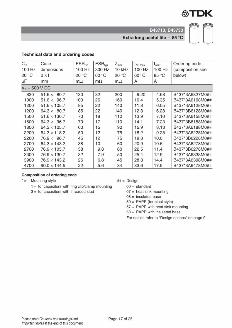
Technical data and ordering codes
CR
100 Hz
20 °C
µF
Case
dimensions
d × l
mm
ESRtyp
100 Hz
20 °C
mΩ
ESRtyp
300 Hz
60 °C
mΩ
Zmax
10 kHz
20 °C
mΩ
IAC,max
100 Hz
60 °C
A
IAC,R
100 Hz
85 °C
A
Ordering code
(composition see
below)
Composition of ordering code
* = Mounting style ## = Design
1 = for capacitors with ring clip/clamp mounting
3 = for capacitors with threaded stud
00 = standard
07 = heat sink mounting
08 = insulated base
50 = PAPR (terminal style)
57 = PAPR with heat sink mounting
58 = PAPR with insulated base
For details refer to "Design options" on page 9.
VR = 200 V DC
3300 51.6 × 80.7 50 15 85 15.8 8.59 B437*3A2338M0##
3900 51.6 × 96.7 40 12 70 17.9 9.78 B437*3A2398M0##
4700 51.6 × 105.7 36 11 60 20.1 10.9 B437*3A2478M0##
4700 64.3 × 80.7 36 10 60 21.0 11.4 B437*3B2478M0##
5600 51.6 × 118.2 30 9.1 50 22.5 12.2 B437*3A2568M0##
5600 64.3 × 96.7 30 8.3 50 23.6 12.9 B437*3B2568M0##
6800 64.3 × 96.7 26 7.7 45 25.8 14.0 B437*3A2688M0##
8200 64.3 × 118.2 20 6.2 34 29.6 16.0 B437*3A2828M0##
8200 76.9 × 96.7 20 5.6 34 33.1 18.0 B437*3B2828M0##
10000 64.3 × 130.7 17 5.5 30 33.2 18.0 B437*3A2109M0##
10000 76.9 × 105.7 17 4.8 28 36.9 20.0 B437*3B2109M0##
12000 76.9 × 118.2 14 4.1 24 41.2 22.3 B437*3A2129M0##
15000 76.9 × 143.2 11 3.4 19 47.6 25.8 B437*3A2159M0##
15000 90.0 × 120.0 11 3.2 19 51.0 28.4 B437*3B2159M0##
18000 76.9 × 156.2 9.5 3.0 17 53.1 28.8 B437*3A2189M0##
18000 90.0 × 144.5 9.2 2.7 16 57.1 31.8 B437*3B2189M0##
22000 76.9 × 190.7 7.8 2.5 14 61.0 33.9 B437*3A2229M0##
22000 90.0 × 170.0 7.6 2.2 14 64.4 35.9 B437*3B2229M0##
27000 76.9 × 220.7 6.4 2.1 12 70.4 39.0 B437*3A2279M0##
27000 90.0 × 197.0 6.2 1.9 12 72.8 40.6 B437*3B2279M0##
33000 90.0 × 221.0 5.2 1.7 9.8 82.5 45.9 B437*3A2339M0##
B43713, B43733
Extra long useful life 85 °C
Page 12 of 25Please read Cautions and warnings and
Important notes at the end of this document.

Technical data and ordering codes
CR
100 Hz
20 °C
µF
Case
dimensions
d × l
mm
ESRtyp
100 Hz
20 °C
mΩ
ESRtyp
300 Hz
60 °C
mΩ
Zmax
10 kHz
20 °C
mΩ
IAC,max
100 Hz
60 °C
A
IAC,R
100 Hz
85 °C
A
Ordering code
(composition see
below)
Composition of ordering code
* = Mounting style ## = Design
1 = for capacitors with ring clip/clamp mounting
3 = for capacitors with threaded stud
00 = standard
07 = heat sink mounting
08 = insulated base
50 = PAPR (terminal style)
57 = PAPR with heat sink mounting
58 = PAPR with insulated base
For details refer to "Design options" on page 9.
VR = 250 V DC
2700 51.6 × 80.7 55 16 95 13.6 7.28 B437*3E2278M0##
3300 51.6 × 80.7 50 15 80 14.8 7.88 B437*3E2338M0##
3900 51.6 × 105.7 36 11 55 18.2 9.69 B437*3E2398M0##
3900 64.3 × 80.7 34 10 55 18.9 10.0 B437*3F2398M0##
4700 51.6 × 130.7 28 8.7 50 21.1 11.2 B437*3E2478M0##
4700 64.3 × 96.7 28 8.5 45 21.4 11.4 B437*3F2478M0##
5600 64.3 × 96.7 24 8.0 40 23.2 12.3 B437*3E2568M0##
6800 64.3 × 118.2 20 6.4 34 26.8 14.2 B437*3E2688M0##
6800 76.9 × 96.7 20 5.7 32 29.8 15.8 B437*3F2688M0##
8200 64.3 × 130.7 17 5.7 28 30.1 16.0 B437*3E2828M0##
8200 76.9 × 105.7 17 5.0 28 33.1 17.6 B437*3F2828M0##
10000 76.9 × 118.2 14 4.2 22 37.3 19.9 B437*3E2109M0##
10000 90.0 × 120.0 13 3.6 22 41.2 22.5 B437*3F2109M0##
12000 76.9 × 143.2 11 3.5 19 42.3 22.5 B437*3E2129M0##
12000 90.0 × 120.0 11 3.4 19 45.3 24.7 B437*3F2129M0##
15000 76.9 × 168.7 9.2 2.9 16 49.0 26.7 B437*3E2159M0##
15000 90.0 × 144.5 9.0 2.7 15 51.8 28.3 B437*3F2159M0##
18000 76.9 × 190.7 7.8 2.6 14 55.4 30.2 B437*3E2189M0##
18000 90.0 × 170.0 7.6 2.3 13 58.0 31.7 B437*3F2189M0##
22000 76.9 × 220.7 6.4 2.2 12 63.8 34.8 B437*3E2229M0##
22000 90.0 × 197.0 6.2 2.0 11 65.6 35.9 B437*3F2229M0##
27000 90.0 × 221.0 5.2 1.7 9.4 74.7 40.8 B437*3E2279M0##
B43713, B43733
Extra long useful life 85 °C
Page 13 of 25Please read Cautions and warnings and
Important notes at the end of this document.

Technical data and ordering codes
CR
100 Hz
20 °C
µF
Case
dimensions
d × l
mm
ESRtyp
100 Hz
20 °C
mΩ
ESRtyp
300 Hz
60 °C
mΩ
Zmax
10 kHz
20 °C
mΩ
IAC,max
100 Hz
60 °C
A
IAC,R
100 Hz
85 °C
A
Ordering code
(composition see
below)
Composition of ordering code
* = Mounting style ## = Design
1 = for capacitors with ring clip/clamp mounting
3 = for capacitors with threaded stud
00 = standard
07 = heat sink mounting
08 = insulated base
50 = PAPR (terminal style)
57 = PAPR with heat sink mounting
58 = PAPR with insulated base
For details refer to "Design options" on page 9.
VR = 350 V DC
1500 51.6 × 80.7 80 22 130 11.8 6.44 B437*3A4158M0##
1800 51.6 × 96.7 65 18 110 13.4 7.33 B437*3A4188M0##
2200 51.6 × 105.7 55 15 90 15.2 8.32 B437*3A4228M0##
2200 64.3 × 80.7 55 15 90 15.9 8.67 B437*3B4228M0##
2700 51.6 × 118.2 45 13 75 17.5 9.52 B437*3A4278M0##
2700 64.3 × 80.7 45 13 75 17.6 9.59 B437*3B4278M0##
3300 64.3 × 96.7 38 11 60 20.2 11.0 B437*3A4338M0##
3900 64.3 × 105.7 32 9.4 55 22.5 12.2 B437*3A4398M0##
3900 76.9 × 96.7 30 8.1 50 25.1 13.6 B437*3B4398M0##
4700 64.3 × 130.7 26 7.6 45 25.7 13.9 B437*3A4478M0##
4700 76.9 × 96.7 26 7.3 45 27.8 15.1 B437*3B4478M0##
5600 64.3 × 143.2 22 6.7 36 28.8 15.6 B437*3A4568M0##
5600 76.9 × 118.2 22 5.9 36 31.3 17.0 B437*3B4568M0##
6800 76.9 × 130.7 18 5.1 30 35.3 19.1 B437*3A4688M0##
6800 90.0 × 120.0 18 4.7 30 38.0 21.2 B437*3B4688M0##
8200 76.9 × 156.2 16 4.2 26 39.4 21.5 B437*3A4828M0##
8200 90.0 × 120.0 15 4.2 24 42.2 23.5 B437*3B4828M0##
10000 76.9 × 168.7 13 3.7 22 45.0 25.0 B437*3A4109M0##
10000 90.0 × 144.5 12 3.5 20 47.7 26.6 B437*3B4109M0##
12000 76.9 × 220.7 11 3.0 18 51.1 28.5 B437*3A4129M0##
15000 90.0 × 197.0 8.6 2.5 15 60.9 34.0 B437*3A4159M0##
18000 90.0 × 221.0 7.2 2.2 13 68.8 38.3 B437*3A4189M0##
B43713, B43733
Extra long useful life 85 °C
Page 14 of 25Please read Cautions and warnings and
Important notes at the end of this document.

Technical data and ordering codes
CR
100 Hz
20 °C
µF
Case
dimensions
d × l
mm
ESRtyp
100 Hz
20 °C
mΩ
ESRtyp
300 Hz
60 °C
mΩ
Zmax
10 kHz
20 °C
mΩ
IAC,max
100 Hz
60 °C
A
IAC,R
100 Hz
85 °C
A
Ordering code
(composition see
below)
Composition of ordering code
* = Mounting style ## = Design
1 = for capacitors with ring clip/clamp mounting
3 = for capacitors with threaded stud
00 = standard
07 = heat sink mounting
08 = insulated base
50 = PAPR (terminal style)
57 = PAPR with heat sink mounting
58 = PAPR with insulated base
For details refer to "Design options" on page 9.
VR = 400 V DC
1500 51.6 × 80.7 85 22 130 11.8 6.44 B437*3A9158M0##
1800 51.6 × 96.7 70 18 110 13.4 7.33 B437*3A9188M0##
2200 51.6 × 105.7 55 15 90 15.3 8.34 B437*3A9228M0##
2200 64.3 × 80.7 55 15 90 15.9 8.66 B437*3B9228M0##
2700 51.6 × 118.2 45 13 75 17.5 9.55 B437*3A9278M0##
2700 64.3 × 80.7 45 14 75 17.6 9.59 B437*3B9278M0##
3300 64.3 × 96.7 38 11 65 20.2 11.0 B437*3A9338M0##
3900 64.3 × 105.7 32 9.7 55 22.5 12.2 B437*3A9398M0##
3900 76.9 × 96.7 32 8.3 50 25.1 13.6 B437*3B9398M0##
4700 64.3 × 130.7 28 7.8 45 25.8 14.0 B437*3A9478M0##
4700 76.9 × 96.7 26 7.5 45 27.9 15.1 B437*3B9478M0##
5600 64.3 × 143.2 24 6.9 38 29.0 15.7 B437*3A9568M0##
5600 76.9 × 118.2 22 6.1 36 31.3 17.0 B437*3B9568M0##
6800 76.9 × 130.7 19 5.2 30 35.4 19.2 B437*3A9688M0##
6800 90.0 × 120.0 18 4.8 30 38.1 21.2 B437*3B9688M0##
8200 76.9 × 168.7 14 4.0 22 42.4 23.6 B437*3A9828M0##
8200 90.0 × 120.0 15 4.4 26 42.3 23.5 B437*3B9828M0##
10000 76.9 × 220.7 11 3.2 18 48.7 27.1 B437*3A9109M0##
10000 90.0 × 144.5 13 3.6 22 48.0 26.7 B437*3B9109M0##
12000 90.0 × 197.0 9.5 2.7 16 56.4 31.4 B437*3A9129M0##
15000 90.0 × 221.0 7.7 2.3 13 65.8 36.6 B437*3A9159M0##
B43713, B43733
Extra long useful life 85 °C
Page 15 of 25Please read Cautions and warnings and
Important notes at the end of this document.

Technical data and ordering codes
CR
100 Hz
20 °C
µF
Case
dimensions
d × l
mm
ESRtyp
100 Hz
20 °C
mΩ
ESRtyp
300 Hz
60 °C
mΩ
Zmax
10 kHz
20 °C
mΩ
IAC,max
100 Hz
60 °C
A
IAC,R
100 Hz
85 °C
A
Ordering code
(composition see
below)
Composition of ordering code
* = Mounting style ## = Design
1 = for capacitors with ring clip/clamp mounting
3 = for capacitors with threaded stud
00 = standard
07 = heat sink mounting
08 = insulated base
50 = PAPR (terminal style)
57 = PAPR with heat sink mounting
58 = PAPR with insulated base
For details refer to "Design options" on page 9.
VR = 450 V DC
1000 51.6 × 80.7 120 28 190 9.62 5.29 B437*3A5108M0##
1200 51.6 × 96.7 100 24 160 10.8 5.99 B437*3A5128M0##
1500 51.6 × 105.7 80 20 130 12.6 6.95 B437*3A5158M0##
1500 64.3 × 80.7 80 19 130 13.1 7.20 B437*3B5158M0##
1800 51.6 × 130.7 65 16 110 14.4 7.95 B437*3A5188M0##
1800 64.3 × 96.7 65 16 110 14.7 8.10 B437*3B5188M0##
2200 64.3 × 105.7 55 14 85 16.7 9.20 B437*3A5228M0##
2700 64.3 × 118.2 45 11 70 19.1 10.5 B437*3A5278M0##
2700 76.9 × 96.7 45 11 70 20.8 11.4 B437*3B5278M0##
3300 64.3 × 143.2 36 9.3 60 21.9 12.0 B437*3A5338M0##
3300 76.9 × 105.7 36 9.0 60 23.5 12.9 B437*3B5338M0##
3900 76.9 × 118.2 30 7.7 50 26.1 14.3 B437*3A5398M0##
4700 76.9 × 143.2 26 6.4 40 29.4 16.2 B437*3A5478M0##
4700 90.0 × 120.0 26 6.2 40 31.4 17.6 B437*3B5478M0##
5600 76.9 × 156.2 22 5.5 34 33.1 18.2 B437*3A5568M0##
5600 90.0 × 144.5 22 5.2 34 34.6 19.5 B437*3B5568M0##
6800 76.9 × 190.7 18 4.6 28 37.8 21.3 B437*3A5688M0##
6800 90.0 × 170.0 17 4.4 28 39.0 22.0 B437*3B5688M0##
8200 76.9 × 220.7 15 3.9 24 43.2 24.4 B437*3A5828M0##
8200 90.0 × 170.0 15 3.8 24 44.4 25.0 B437*3B5828M0##
10000 90.0 × 221.0 12 3.1 20 50.2 28.3 B437*3A5109M0##
B43713, B43733
Extra long useful life 85 °C
Page 16 of 25Please read Cautions and warnings and
Important notes at the end of this document.
Technical data and ordering codes
CR
100 Hz
20 °C
µF
Case
dimensions
d × l
mm
ESRtyp
100 Hz
20 °C
mΩ
ESRtyp
300 Hz
60 °C
mΩ
Zmax
10 kHz
20 °C
mΩ
IAC,max
100 Hz
60 °C
A
IAC,R
100 Hz
85 °C
A
Ordering code
(composition see
below)
Composition of ordering code
* = Mounting style ## = Design
1 = for capacitors with ring clip/clamp mounting
3 = for capacitors with threaded stud
00 = standard
07 = heat sink mounting
08 = insulated base
50 = PAPR (terminal style)
57 = PAPR with heat sink mounting
58 = PAPR with insulated base
For details refer to "Design options" on page 9.
VR = 500 V DC
820 51.6 × 80.7 130 32 200 9.20 4.68 B437*3A6827M0##
1000 51.6 × 96.7 100 26 160 10.4 5.35 B437*3A6108M0##
1200 51.6 × 105.7 85 22 140 11.8 6.05 B437*3A6128M0##
1200 64.3 × 80.7 85 22 140 12.3 6.28 B437*3B6128M0##
1500 51.6 × 130.7 70 18 110 13.9 7.10 B437*3A6158M0##
1500 64.3 × 96.7 70 17 110 14.1 7.23 B437*3B6158M0##
1800 64.3 × 105.7 60 15 90 15.9 8.13 B437*3A6188M0##
2200 64.3 × 118.2 50 12 75 18.2 9.28 B437*3A6228M0##
2200 76.9 × 96.7 45 12 75 19.8 10.0 B437*3B6228M0##
2700 64.3 × 143.2 38 10 60 20.9 10.6 B437*3A6278M0##
2700 76.9 × 105.7 38 9.8 60 22.5 11.4 B437*3B6278M0##
3300 76.9 × 130.7 32 7.9 50 25.4 12.9 B437*3A6338M0##
3900 76.9 × 143.2 26 6.8 45 28.3 14.4 B437*3A6398M0##
4700 90.0 × 144.5 22 5.6 34 33.6 17.5 B437*3A6478M0##
B43713, B43733
Extra long useful life 85 °C
Page 17 of 25Please read Cautions and warnings and
Important notes at the end of this document.

1) Refer to chapter "General technical information, 5 Useful life" on how to interpret useful life.
Useful life1)
For useful life calculations, please use our web-based "AlCap Useful Life Calculation Tool", which
can be found on the Internet under the following link:
http://www.epcos.com/designtools/alu_useful_life/Useful_life.swf
The AlCap Useful Life Calculation Tool provides calculations of useful life as well as additional
data for selected capacitor types under operating conditions defined by the user.
Frequency characteristics of ESR
Typical behavior
Impedance Z versus frequency f
Typical behavior at 20 °C
B43713, B43733
Extra long useful life 85 °C
Page 18 of 25Please read Cautions and warnings and
Important notes at the end of this document.

Cautions and warnings
Personal safety
The electrolytes used by EPCOS have been optimized both with a view to the intended
application and with regard to health and environmental compatibility. They do not contain any
solvents that are detrimental to health, e.g. dimethyl formamide (DMF) or dimethyl acetamide
(DMAC).
Furthermore, some of the high-voltage electrolytes used by EPCOS are self-extinguishing.
As far as possible, EPCOS does not use any dangerous chemicals or compounds to produce
operating electrolytes, although in exceptional cases, such materials must be used in order to
achieve specific physical and electrical properties because no alternative materials are currently
known. We do, however, restrict the amount of dangerous materials used in our products to an
absolute minimum.
Materials and chemicals used in EPCOS aluminum electrolytic capacitors are continuously
adapted in compliance with the EPCOS Corporate Environmental Policy and the latest EU
regulations and guidelines such as RoHS, REACH/SVHC, GADSL, and ELV.
MDS (Material Data Sheets) are available on the EPCOS website for all types listed in the data
book. MDS for customer specific capacitors are available upon request.
MSDS (Material Safety Data Sheets) are available for all of our electrolytes upon request.
Nevertheless, the following rules should be observed when handling aluminum electrolytic
capacitors: No electrolyte should come into contact with eyes or skin. If electrolyte does come
into contact with the skin, wash the affected areas immediately with running water. If the eyes
are affected, rinse them for 10 minutes with plenty of water. If symptoms persist, seek medical
treatment. Avoid inhaling electrolyte vapor or mists. Workplaces and other affected areas should
be well ventilated. Clothing that has been contaminated by electrolyte must be changed and
rinsed in water.
B43713, B43733
Extra long useful life 85 °C
Page 19 of 25Please read Cautions and warnings and
Important notes at the end of this document.

Product safety
The table below summarizes the safety instructions that must be observed without fail. A detailed
description can be found in the relevant sections of chapter "General technical information".
Topic Safety information Reference
chapter "General
technical information"
Polarity Make sure that polar capacitors are connected
with the right polarity.
1
"Basic construction of
aluminum electrolytic
capacitors"
Reverse voltage Voltages of opposite polarity should be prevented
by connecting a diode.
3.1.6
"Reverse voltage"
Mounting
position of screw-
terminal capacitors
Screw terminal capacitors must not be mounted
with terminals facing down unless otherwise
specified.
11.1.
"Mounting positions of
capacitors with screw
terminals"
Robustness of
terminals
The following maximum tightening torques must
not be exceeded when connecting screw
terminals:
M5: 2.5 Nm
M6: 4.0 Nm
11.3
"Mounting torques"
Mounting of
single-ended
capacitors
The internal structure of single-ended capacitors
might be damaged if excessive force is applied to
the lead wires.
Avoid any compressive, tensile or flexural stress.
Do not move the capacitor after soldering to PC
board.
Do not pick up the PC board by the soldered
capacitor.
Do not insert the capacitor on the PC board with a
hole space different to the lead space specified.
11.4
"Mounting
considerations for
single-ended capacitors"
Soldering Do not exceed the specified time or temperature
limits during soldering.
11.5
"Soldering"
Soldering,
cleaning agents
Do not allow halogenated hydrocarbons to come
into contact with aluminum electrolytic capacitors.
11.6
"Cleaning agents"
Upper category
temperature
Do not exceed the upper category temperature. 7.2
"Maximum permissible
operating temperature"
Passive
flammability
Avoid external energy, e.g. fire. 8.1
"Passive flammability"
B43713, B43733
Extra long useful life 85 °C
Page 20 of 25Please read Cautions and warnings and
Important notes at the end of this document.
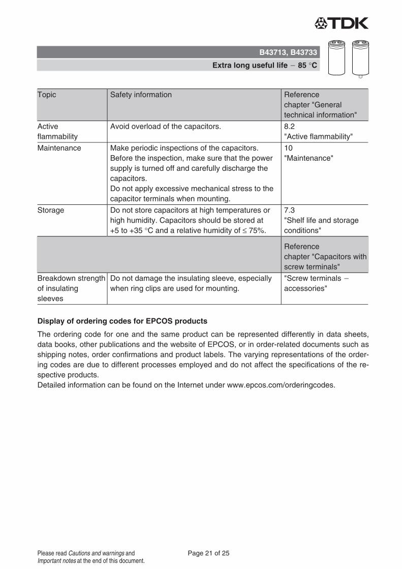
Topic Safety information Reference
chapter "General
technical information"
Active
flammability
Avoid overload of the capacitors. 8.2
"Active flammability"
Maintenance Make periodic inspections of the capacitors.
Before the inspection, make sure that the power
supply is turned off and carefully discharge the
capacitors.
Do not apply excessive mechanical stress to the
capacitor terminals when mounting.
10
"Maintenance"
Storage Do not store capacitors at high temperatures or
high humidity. Capacitors should be stored at
+5 to +35 °C and a relative humidity of ≤ 75%.
7.3
"Shelf life and storage
conditions"
Reference
chapter "Capacitors with
screw terminals"
Breakdown strength
of insulating
sleeves
Do not damage the insulating sleeve, especially
when ring clips are used for mounting.
"Screw terminals
accessories"
Display of ordering codes for EPCOS products
The ordering code for one and the same product can be represented differently in data sheets,
data books, other publications and the website of EPCOS, or in order-related documents such as
shipping notes, order confirmations and product labels. The varying representations of the order-
ing codes are due to different processes employed and do not affect the specifications of the re-
spective products.
Detailed information can be found on the Internet under www.epcos.com/orderingcodes.
B43713, B43733
Extra long useful life 85 °C
Page 21 of 25Please read Cautions and warnings and
Important notes at the end of this document.

Symbols and terms
Symbol English German
C Capacitance Kapazität
CR Rated capacitance Nennkapazität
CS Series capacitance Serienkapazität
CS,T Series capacitance at temperature T Serienkapazität bei Temperatur T
Cf Capacitance at frequency f Kapazität bei Frequenz f
d Case diameter, nominal dimension Gehäusedurchmesser, Nennmaß
dmax Maximum case diameter Maximaler Gehäusedurchmesser
ESL Self-inductance Eigeninduktivität
ESR Equivalent series resistance Ersatzserienwiderstand
ESRf Equivalent series resistance at
frequency f
Ersatzserienwiderstand bei Frequenz f
ESRT Equivalent series resistance at
temperature T
Ersatzserienwiderstand bei Temperatur T
f Frequency Frequenz
I Current Strom
IAC Alternating current (ripple current) Wechselstrom
IAC,RMS Root-mean-square value of alternating
current
Wechselstrom, Effektivwert
IAC,f Ripple current at frequency f Wechselstrom bei Frequenz f
IAC,max Maximum permissible ripple current Maximal zulässiger Wechselstrom
IAC,R Rated ripple current Nennwechselstrom
Ileak Leakage current Reststrom
Ileak,op Operating leakage current Betriebsreststrom
l Case length, nominal dimension Gehäuselänge, Nennmaß
lmax Maximum case length (without
terminals and mounting stud)
Maximale Gehäuselänge (ohne Anschlüsse
und Gewindebolzen)
R Resistance Widerstand
Rins Insulation resistance Isolationswiderstand
Rsymm Balancing resistance Symmetrierwiderstand
T Temperature Temperatur
ΔT Temperature difference Temperaturdifferenz
TA Ambient temperature Umgebungstemperatur
TC Case temperature Gehäusetemperatur
TB Capacitor base temperature Temperatur des Gehäusebodens
t Time Zeit
Δt Period Zeitraum
tb Service life (operating hours) Brauchbarkeitsdauer (Betriebszeit)
B43713, B43733
Extra long useful life 85 °C
Page 22 of 25Please read Cautions and warnings and
Important notes at the end of this document.

Symbol English German
V Voltage Spannung
VF Forming voltage Formierspannung
Vop Operating voltage Betriebsspannung
VR Rated voltage, DC voltage Nennspannung, Gleichspannung
VS Surge voltage Spitzenspannung
XC Capacitive reactance Kapazitiver Blindwiderstand
XL Inductive reactance Induktiver Blindwiderstand
Z Impedance Scheinwiderstand
ZT Impedance at temperature T Scheinwiderstand bei Temperatur T
tan δ Dissipation factor Verlustfaktor
λ Failure rate Ausfallrate
ε0 Absolute permittivity Elektrische Feldkonstante
εr Relative permittivity Dielektrizitätszahl
ω Angular velocity; 2 π f Kreisfrequenz; 2 π f
Note
All dimensions are given in mm.
B43713, B43733
Extra long useful life 85 °C
Page 23 of 25Please read Cautions and warnings and
Important notes at the end of this document.

The following applies to all products named in this publication:
1. Some parts of this publication contain statements about the suitability of our products for
certain areas of application. These statements are based on our knowledge of typical re-
quirements that are often placed on our products in the areas of application concerned. We
nevertheless expressly point out that such statements cannot be regarded as binding
statements about the suitability of our products for a particular customer application.
As a rule, EPCOS is either unfamiliar with individual customer applications or less familiar
with them than the customers themselves. For these reasons, it is always ultimately incum-
bent on the customer to check and decide whether an EPCOS product with the properties de-
scribed in the product specification is suitable for use in a particular customer application.
2. We also point out that in individual cases, a malfunction of electronic components or
failure before the end of their usual service life cannot be completely ruled out in the
current state of the art, even if they are operated as specified. In customer applications
requiring a very high level of operational safety and especially in customer applications in
which the malfunction or failure of an electronic component could endanger human life or
health (e.g. in accident prevention or lifesaving systems), it must therefore be ensured by
means of suitable design of the customer application or other action taken by the customer
(e.g. installation of protective circuitry or redundancy) that no injury or damage is sustained by
third parties in the event of malfunction or failure of an electronic component.
3. The warnings, cautions and product-specific notes must be observed.
4. In order to satisfy certain technical requirements, some of the products described in this
publication may contain substances subject to restrictions in certain jurisdictions (e.g.
because they are classed as hazardous). Useful information on this will be found in our Ma-
terial Data Sheets on the Internet (www.epcos.com/material). Should you have any more de-
tailed questions, please contact our sales offices.
5. We constantly strive to improve our products. Consequently, the products described in this
publication may change from time to time. The same is true of the corresponding product
specifications. Please check therefore to what extent product descriptions and specifications
contained in this publication are still applicable before or when you place an order. We also
reserve the right to discontinue production and delivery of products. Consequently, we
cannot guarantee that all products named in this publication will always be available. The
aforementioned does not apply in the case of individual agreements deviating from the fore-
going for customer-specific products.
6. Unless otherwise agreed in individual contracts, all orders are subject to the current ver-
sion of the "General Terms of Delivery for Products and Services in the Electrical In-
dustry" published by the German Electrical and Electronics Industry Association
(ZVEI).
Important notes
Page 24 of 25
7. The trade names EPCOS, CeraDiode, CeraLink, CeraPad, CeraPlas, CSMP, CSSP, CTVS,
DeltaCap, DigiSiMic, DSSP, ExoCore, FilterCap, FormFit, LeaXield, MiniBlue, MiniCell, MKD,
MKK, MotorCap, PCC, PhaseCap, PhaseCube, PhaseMod, PhiCap, PQSine, SIFERRIT,
SIFI, SIKOREL, SilverCap, SIMDAD, SiMic, SIMID, SineFormer, SIOV, SIP5D, SIP5K, TFAP,
ThermoFuse, WindCap are trademarks registered or pending in Europe and in other coun-
tries. Further information will be found on the Internet at www.epcos.com/trademarks.
Important notes
Page 25 of 25