online monitoring of aluminum electrolytic capacitors in
TRANSCRIPT
IEEE SENSORS JOURNAL, VOL. 20, NO. 2, JANUARY 15, 2020 767
Online Monitoring of Aluminum ElectrolyticCapacitors in Photovoltaic Systems by
Magnetoresistive SensorsWenchao Miao , K. H. Lam, and Philip W. T. Pong , Senior Member, IEEE
Abstract—Due to the environmental concerns and newenergy policies, worldwide expectations for energy pro-duction utilizing photovoltaic (PV) systems are increasingsignificantly. The aluminum electrolytic capacitor (AEC) isextensively used in filtering application for power electronicconverters in PV systems since they can achieve the highestenergy density with the lowest cost. However, the lifetimeof an AEC is limited due to the electrolyte vaporization. Thedegradation of AECs challenges the efficiency and reliabilityof a PV system. Therefore, the health-monitoring of AECs isindispensable for the PV systems to operate reliably. In thispaper, an online AEC-monitoring scheme based on magnetic-field sensing is proposed for PV systems under variousworking conditions. The AEC-monitoring technique using the equivalent series resistance (ESR) and capacitance (C) asthe health indicators were developed for the power electronic converters in PV systems. The proposed methodologyconsidering the voltage drops on C can improve the accuracy in ESR-estimation and achieve the estimation of C. Thesimulation results with Simulink verified that the proposed method was capable of estimating the health indicatorsaccurately over various levels of solar irradiance and ambient temperature. The tunneling magnetoresistive (TMR) sensorswere pre-calibrated from -25 to 100◦ C for implementation in PV systems. The experimental results proved that TMRsensors could measure the current of AECs effectively to achieve the precise estimations of the health indicators usingthe proposed technique. This technique is non-invasive, compact, and cost-effective since it can be realized with the TMRsensors or other MR sensors.
Index Terms— Aluminum electrolytic capacitor, condition monitoring, PV system, tunneling magnetoresistive sensor.
I. INTRODUCTION
PHOTOVOLTAIC (PV) systems are one of the mostpopular renewable energy systems, and the installation
of PV systems has been growing rapidly. According tothe International Renewable Energy Agency (IRENA),the cumulative global PV installations reached 480 GW
Manuscript received September 17, 2019; accepted October 3,2019. Date of publication October 7, 2019; date of current versionDecember 31, 2019. This work was supported in part by the SeedFunding Program for Basic Research, in part by the Seed FundingProgram for Applied Research, in part by the Small Project FundingProgram from The University of Hong Kong, Hong Kong, in part bythe Innovation and Technology Fund (ITF) Tier 3 Funding under GrantITS/203/14, Grant ITS/104/13, and Grant ITS/214/14, in part by theResearch Grants Council-General Research Fund (RGC-GRF) underGrant HKU 17204617, and in part by the University Grants Committeeof Hong Kong under Contract AoE/P-04/08. The associate editor coor-dinating the review of this article and approving it for publication wasProf. Boby George. (Corresponding author: Philip W. T. Pong.)
The authors are with the Department of Electrical and ElectronicEngineering, The University of Hong Kong, Hong Kong (e-mail:[email protected]).
Digital Object Identifier 10.1109/JSEN.2019.2945943
at the end of 2018 [1]. In the system level, there areground faults, line-line faults, overcurrent faults and arc faultsin a PV system [2]. The abnormal conditions of devices alsohinder the normal operation of a PV system. In PV systems,the aluminum electrolytic capacitors (AECs) are widely usedfor filtering applications in power electronic converters dueto their high energy density and low cost [3]–[5]. However,the electrolyte vaporization, which leads to a decrease incapacitance (C) and an increase in equivalent series resis-tance (ESR), restricts the lifetime of an AEC [3]. It is claimedthat about 30 % of the failures in power electronic convertersare caused by AECs [5], [6]. The AEC is one of the mostvulnerable components in power electronic converters andchallenges the reliability and efficiency of PV systems [7]–[9].Therefore, the condition monitoring of AECs is essential toensure the reliability and efficiency of PV systems.
It is a consensus that an AEC is worn out when its Creduces by 20%, or the ESR doubles its original value.Currently, the condition-monitoring techniques of AECs aremainly based on the estimations of their ESRs and Cs. The
1558-1748 © 2019 IEEE. Personal use is permitted, but republication/redistribution requires IEEE permission.See http://www.ieee.org/publications_standards/publications/rights/index.html for more information.
Authorized licensed use limited to: The University of Hong Kong Libraries. Downloaded on November 25,2020 at 09:37:55 UTC from IEEE Xplore. Restrictions apply.
768 IEEE SENSORS JOURNAL, VOL. 20, NO. 2, JANUARY 15, 2020
condition-monitoring techniques can be classified as offlinewhen an interruption of the system is required to acquire thehealth indicator or quasi-online when the health indicator isattained during the routine pause of the system or online whenthe health indicator can be obtained during the operationof the system [4], [10]. Although the offline [11]–[13] andquasi-online [14], [15] techniques adopting injected signalscan achieve the estimations of ESRs and Cs, the reliability andefficiency of the systems are jeopardized by the interruptions.The online techniques utilizing the electrical circuits are ableto monitor the AECs [16], [17], but the circuits need tobe specially designed for applications in different systemsand thus incurring extra costs. The specific equations tocalculate the ESRs and Cs of AECs in power converters arederived in [18]–[21]. However, different methodologies arerequired for each topology of power converters. They cannotbe applied in other power converters.
The online ripple method of using the voltage and currentripples of AECs can estimate the ESRs and Cs [22]–[28].The voltage across the C of an AEC is neglected in theripple method. However, there are cases that the voltage acrossthe C is not negligible [12], [29]. As a result, the accu-racy of this ripple method is not guaranteed. Albeit con-dition monitoring of AECs in PV systems also have beenresearched [4], [5], [8], [9], [30], the working conditions of PVsystems vary with the levels of solar irradiance and ambienttemperature. The ESRs and Cs of AECs are affected bythe capacitor core temperature [24]. Hence, a comprehensiveonline AEC-monitoring technique for PV systems working invarious conditions is desirable.
Furthermore, parasitic impedance (Z) is induced bythe shunt resistor used for current measurement, whichstresses the normal operation of power electronic converters[26]. The Hall-effect current transducers can attain thecurrent ripples of AECs [4], [5], [8], [27], [30]. However,a magnetic concentrator concentrates the magnetic field ofthe target current is required by the current transducer, whichlargely increases the volume and expense of the device[31]. Besides, the bandwidth of the Hall sensor is limited,which is generally lower than 200 kHz [31]. Therefore,the Hall-effect current transducer of relatively large size, highcost, and narrow bandwidth is not applicable in measuringthe high-frequency current in power electronic converters.Additionally, the performance of most current sensors istemperature dependent [31]. Hence, it is necessary to acquirethe temperature effects on current sensors for implementationsunder various conditions in PV systems. In this way,the temperature effects on current sensors can be considered byusing a thermistor to measure the temperature simultaneously.
In this paper, the voltage drops on C is considered in theproposed method to improve the accuracy of ESR-estimationand the equation to estimate C is derived. The tunneling mag-netoresistive (TMR) sensor, which is competent for measuringthe magnetic field [32]–[34], can be utilized to sense the cur-rent of AECs up to 1 MHz non-invasively. The low-cost TMRsensor is compact in size (typically less than 15 mm3) andconsume very little power (typically less than 0.4 mW), and itcan be integrated on the printed circuit boards (PCBs) of power
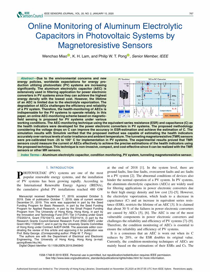
Fig. 1. The characteristics of AECs, (a) the equivalent circuit, (b) thephasor diagram of the voltage of an AEC, and (c) Zs of the AECs in 680,820, and 1500 μF from 20 Hz to 300 kHz at 25 ◦C.
converters to measure the current effectively. The temperatureeffects on the TMR sensor was determined for implementa-tions in PV systems. Thermistors were used to measure thetemperatures of AECs for estimations of ESRs and Cs. A PVsystem was developed on Simulink to verify the proposedtechnique. The experimental results with the PV simulatorconfirmed that the proposed method could realize the onlineestimations of ESRs and Cs accurately under various work-ing conditions. The proposed technique is also feasible forAEC-monitoring in other power electronic systems.
This paper is organized as follows. In Section II, the charac-teristics of AECs and principles of the AEC-monitoring tech-nique are illustrated. The method to estimate the ESRs and Csbased on magnetic-field sensing are proposed. In Section III,the PV system is developed on Simulink to verify the proposedmethodology in various conditions. In Section IV, the tech-nique is verified by the experimental results with the PVsimulator. The conclusion is drawn in Section V.
II. PRINCIPLES OF AEC AND ONLINE-MONITORING
METHODOLOGY BASED ON MAGNETIC-FIELD SENSING
A. Characteristics and Condition-MonitoringMethod of AEC
The simplified equivalent circuit of an AEC consists of C,ESR, and equivalent series inductance (ESL) as Fig. 1 (a)depicts. Therefore, the Z of an AEC can be expressed byEq. (1).
Z = 1/ jωC + ESR + jωESL (1)
where ω is the frequency of current, Ic.Hence, the voltage across the AEC can be calculated as
V = (1/ jωC + ESR + jωESL) · I C (2)
Therefore, the Z of an AEC can be attained by using thevoltage and current ripples of the AEC. Since this ripplemethod is affected by the transient values of voltage andcurrent ripples, the fundamental components of the voltageand current ripples should be used as expressed by Eq. (3).
Z = �V f /�I C_ f (3)
Authorized licensed use limited to: The University of Hong Kong Libraries. Downloaded on November 25,2020 at 09:37:55 UTC from IEEE Xplore. Restrictions apply.
MIAO et al.: ONLINE MONITORING OF AECs IN PV SYSTEMS BY MAGNETORESISTIVE SENSORS 769
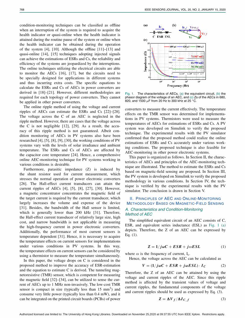
Fig. 2. The ESR at 20 kHz and capacitance at 120 Hz of the AECin 680 μF from -25 to 100 ◦C.
The ESR is dominant in the Z and the voltage drops on ESLis negligible when the frequency is in tens to hundreds ofkilohertz [26]. The operation frequency of a power electronicsystem is usually in this frequency range. Therefore, the ESRsof AECs in power electronic systems are calculated by usingEq. (3) in [22], [24], [25], and [27].
However, the voltage drops on C is contributing to thevoltage ripple across the AEC apparently when the frequencyis around several tens of kilohertz. The phasor diagram canbe drawn as depicted in Fig. 1 (b). The current is leading thevoltage by an angle of θ . In this case, the 1/jωC is relativelylarge and cannot be neglected. As shown in Fig. 1 (c),the Zs of the AECs from Nichicon in 680 and 820 μF, andNippon Chemi-Con in 1500 μF decrease with the frequency asmeasured by the LCR meter (BK 891, BK Precision) at 25 ◦C.Although the Zs of the three AECs stay in almost constantvalues at the frequency around tens of kilohertz, their Zs stilldecrease slightly from 10 to 20 kHz to be 74.847, 66.904 and38.294 m� at 20 kHz. This is due to the decreasing of 1/jωC.Therefore, the voltage drops on C is not negligible, and theESR-estimation methodology needs to be further developed.To achieve a higher accuracy of the ESR-estimation [12], [29],the ESR should be calculated by using Eq. (4).
ESR = �V f Cos(θ)/�I C_ f (4)
According to the phasor diagram, Eq. (5) can be deduced toestimate the Cs of AECs.
C = �I C_ f /(�V f Sin(θ)ω) (5)
Thus, the condition-monitoring of AECs can be achieved byestimating their ESRs and Cs by using Eq. (4) and (5).
However, the ESRs and Cs of AECs vary with the tem-perature. The thermal chamber (SH-242, ESPEC) was usedto investigate the temperature effects on AECs. The ESR ofthe AEC of 680 μF decreases with the temperature from -25 to 100 ◦C as shown in Fig. 2. The ESR is 73.224 m�at 25 ◦C which is less than the Z of 74.847 m�. Hence,it verifies that it is essential to consider the voltage drops onC in the estimation of ESR. It is found that the ESR of anAEC decreases exponentially with the temperature [24], [35],and it can be expressed by Eq. (6).
ESR = α + β · e−T C/γ (6)
where α, β, and γ depend on the type of an AEC, Tc is thecapacitor core temperature.
TABLE ITHE FITTING PARAMETERS OF EQ. (7)
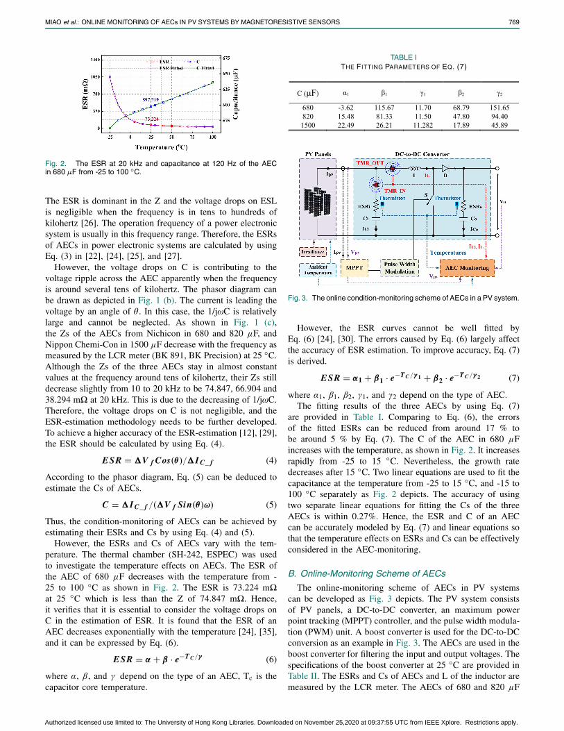
Fig. 3. The online condition-monitoring scheme of AECs in a PV system.
However, the ESR curves cannot be well fitted byEq. (6) [24], [30]. The errors caused by Eq. (6) largely affectthe accuracy of ESR estimation. To improve accuracy, Eq. (7)is derived.
ESR = α1 + β1 · e−T C /γ 1 + β2 · e−T C /γ 2 (7)
where α1, β1, β2, γ1, and γ2 depend on the type of AEC.The fitting results of the three AECs by using Eq. (7)
are provided in Table I. Comparing to Eq. (6), the errorsof the fitted ESRs can be reduced from around 17 % tobe around 5 % by Eq. (7). The C of the AEC in 680 μFincreases with the temperature, as shown in Fig. 2. It increasesrapidly from -25 to 15 ◦C. Nevertheless, the growth ratedecreases after 15 ◦C. Two linear equations are used to fit thecapacitance at the temperature from -25 to 15 ◦C, and -15 to100 ◦C separately as Fig. 2 depicts. The accuracy of usingtwo separate linear equations for fitting the Cs of the threeAECs is within 0.27%. Hence, the ESR and C of an AECcan be accurately modeled by Eq. (7) and linear equations sothat the temperature effects on ESRs and Cs can be effectivelyconsidered in the AEC-monitoring.
B. Online-Monitoring Scheme of AECs
The online-monitoring scheme of AECs in PV systemscan be developed as Fig. 3 depicts. The PV system consistsof PV panels, a DC-to-DC converter, an maximum powerpoint tracking (MPPT) controller, and the pulse width modula-tion (PWM) unit. A boost converter is used for the DC-to-DCconversion as an example in Fig. 3. The AECs are used in theboost converter for filtering the input and output voltages. Thespecifications of the boost converter at 25 ◦C are provided inTable II. The ESRs and Cs of AECs and L of the inductor aremeasured by the LCR meter. The AECs of 680 and 820 μF
Authorized licensed use limited to: The University of Hong Kong Libraries. Downloaded on November 25,2020 at 09:37:55 UTC from IEEE Xplore. Restrictions apply.
770 IEEE SENSORS JOURNAL, VOL. 20, NO. 2, JANUARY 15, 2020
TABLE IISPECIFICATIONS OF THE BOOST CONVERTER AT 25 ◦C
are used as the input capacitor, and the AEC of 1500 μFis used as the output capacitor. According to the proposedapproach, the voltage ripple of PV panels (�Vpv), the currentripple of input AEC (�ICi), the temperature of input AEC,the output voltage ripple (�Vo), the current ripple of outputAEC (�ICo), and the temperature of output AEC are requiredfor the estimations of ESRs and Cs. In a boost converter,the �ICo equals the peak of inductor current (IL) [25], [28],therefore, the inductor current can be measured for theestimations of ESR and C of output AEC. In this way,the two sensors can be placed close to achieve the integrationof the current-measurement circuit on the PCB as shownin Fig. 3.
The Vpv and Vo can be obtained from the PV systemby voltage sensors, and they are also needed in MPPT andcontrol purposes. Therefore, this method does not incur anextra cost. The temperatures of the AECs can be measuredinstantaneously by the thermistors [5], [17], [24], [26], [27].The low-cost and non-invasive TMR sensors can be integratedon the PCB of the converter to measure the magnetic field ofthe ICi and IL. The current is sensed by a TMR sensor basedon the tunneling magnetoresistance effect of a magnetic tunneljunction (MTJ). The target current can be determined by theelectrical resistance of the MTJ which changes as a function ofthe magnetic field emanated from the current [32]. Since thetypical current consumption of a TMR2001 is 16 μA [34],which generates extremely low heat, the temperature of theTMR2001 during operation is almost the same as the ambienttemperature. Therefore, the ambient temperature required inforecasting the performance of PV panels can be used topredict the temperature effects on TMR sensors [36]. Thus,a non-invasive, low-cost, and compact online AEC-monitoringsystem based on magnetic-field sensing can be developed forPV systems.
III. SIMULATIONS OF THE PV SYSTEM ON SIMULINK
The PV system was simulated on Simulink to investigatethe proposed methodologies for estimations of ESRs and Cs ofAECs. The proposed methodologies were verified with the PVsystem in different irradiance and temperature levels. It wasalso studied in transient conditions with the load varied from100 to 50 �.
A. PV System on Simulink
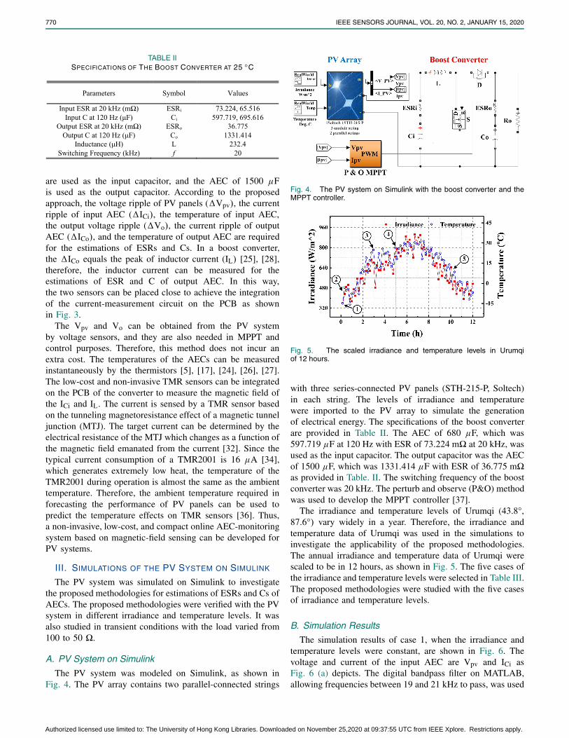
The PV system was modeled on Simulink, as shown inFig. 4. The PV array contains two parallel-connected strings
Fig. 4. The PV system on Simulink with the boost converter and theMPPT controller.
Fig. 5. The scaled irradiance and temperature levels in Urumqiof 12 hours.
with three series-connected PV panels (STH-215-P, Soltech)in each string. The levels of irradiance and temperaturewere imported to the PV array to simulate the generationof electrical energy. The specifications of the boost converterare provided in Table II. The AEC of 680 μF, which was597.719 μF at 120 Hz with ESR of 73.224 m� at 20 kHz, wasused as the input capacitor. The output capacitor was the AECof 1500 μF, which was 1331.414 μF with ESR of 36.775 m�as provided in Table. II. The switching frequency of the boostconverter was 20 kHz. The perturb and observe (P&O) methodwas used to develop the MPPT controller [37].
The irradiance and temperature levels of Urumqi (43.8◦,87.6◦) vary widely in a year. Therefore, the irradiance andtemperature data of Urumqi was used in the simulations toinvestigate the applicability of the proposed methodologies.The annual irradiance and temperature data of Urumqi werescaled to be in 12 hours, as shown in Fig. 5. The five cases ofthe irradiance and temperature levels were selected in Table III.The proposed methodologies were studied with the five casesof irradiance and temperature levels.
B. Simulation Results
The simulation results of case 1, when the irradiance andtemperature levels were constant, are shown in Fig. 6. Thevoltage and current of the input AEC are Vpv and ICi asFig. 6 (a) depicts. The digital bandpass filter on MATLAB,allowing frequencies between 19 and 21 kHz to pass, was used
Authorized licensed use limited to: The University of Hong Kong Libraries. Downloaded on November 25,2020 at 09:37:55 UTC from IEEE Xplore. Restrictions apply.
MIAO et al.: ONLINE MONITORING OF AECs IN PV SYSTEMS BY MAGNETORESISTIVE SENSORS 771
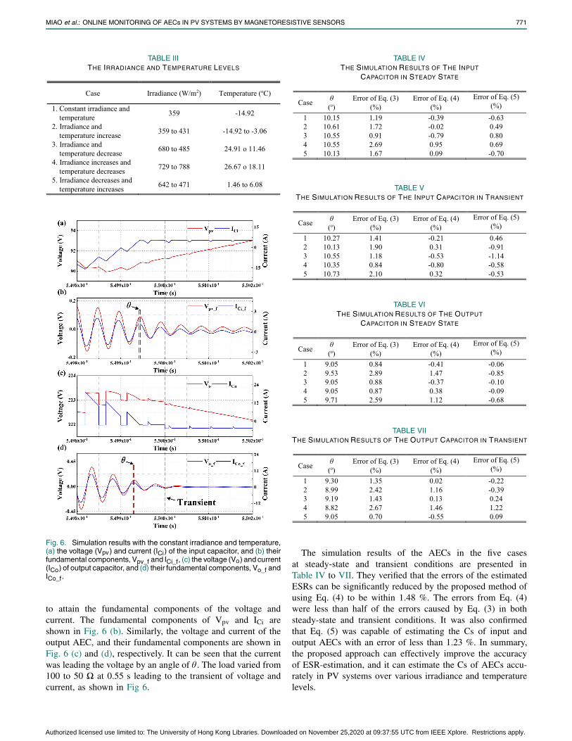
TABLE IIITHE IRRADIANCE AND TEMPERATURE LEVELS
Fig. 6. Simulation results with the constant irradiance and temperature,(a) the voltage (Vpv) and current (ICi) of the input capacitor, and (b) theirfundamental components, Vpv_f and ICi_f, (c) the voltage (Vo) and current(ICo) of output capacitor, and (d) their fundamental components, Vo_f andICo_f.
to attain the fundamental components of the voltage andcurrent. The fundamental components of Vpv and ICi areshown in Fig. 6 (b). Similarly, the voltage and current of theoutput AEC, and their fundamental components are shown inFig. 6 (c) and (d), respectively. It can be seen that the currentwas leading the voltage by an angle of θ . The load varied from100 to 50 � at 0.55 s leading to the transient of voltage andcurrent, as shown in Fig 6.
TABLE IVTHE SIMULATION RESULTS OF THE INPUT
CAPACITOR IN STEADY STATE
TABLE VTHE SIMULATION RESULTS OF THE INPUT CAPACITOR IN TRANSIENT
TABLE VITHE SIMULATION RESULTS OF THE OUTPUT
CAPACITOR IN STEADY STATE
TABLE VIITHE SIMULATION RESULTS OF THE OUTPUT CAPACITOR IN TRANSIENT
The simulation results of the AECs in the five casesat steady-state and transient conditions are presented inTable IV to VII. They verified that the errors of the estimatedESRs can be significantly reduced by the proposed method ofusing Eq. (4) to be within 1.48 %. The errors from Eq. (4)were less than half of the errors caused by Eq. (3) in bothsteady-state and transient conditions. It was also confirmedthat Eq. (5) was capable of estimating the Cs of input andoutput AECs with an error of less than 1.23 %. In summary,the proposed approach can effectively improve the accuracyof ESR-estimation, and it can estimate the Cs of AECs accu-rately in PV systems over various irradiance and temperaturelevels.
Authorized licensed use limited to: The University of Hong Kong Libraries. Downloaded on November 25,2020 at 09:37:55 UTC from IEEE Xplore. Restrictions apply.
772 IEEE SENSORS JOURNAL, VOL. 20, NO. 2, JANUARY 15, 2020
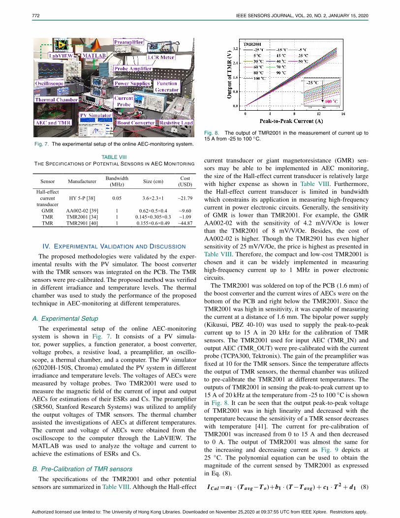
Fig. 7. The experimental setup of the online AEC-monitoring system.
TABLE VIIITHE SPECIFICATIONS OF POTENTIAL SENSORS IN AEC MONITORING
IV. EXPERIMENTAL VALIDATION AND DISCUSSION
The proposed methodologies were validated by the exper-imental results with the PV simulator. The boost converterwith the TMR sensors was integrated on the PCB. The TMRsensors were pre-calibrated. The proposed method was verifiedin different irradiance and temperature levels. The thermalchamber was used to study the performance of the proposedtechnique in AEC-monitoring at different temperatures.
A. Experimental Setup
The experimental setup of the online AEC-monitoringsystem is shown in Fig. 7. It consists of a PV simula-tor, power supplies, a function generator, a boost converter,voltage probes, a resistive load, a preamplifier, an oscillo-scope, a thermal chamber, and a computer. The PV simulator(62020H-150S, Chroma) emulated the PV system in differentirradiance and temperature levels. The voltages of AECs weremeasured by voltage probes. Two TMR2001 were used tomeasure the magnetic field of the current of input and outputAECs for estimations of their ESRs and Cs. The preamplifier(SR560, Stanford Research Systems) was utilized to amplifythe output voltages of TMR sensors. The thermal chamberassisted the investigations of AECs at different temperatures.The current and voltage of AECs were obtained from theoscilloscope to the computer through the LabVIEW. TheMATLAB was used to analyze the voltage and current toachieve the estimations of ESRs and Cs.
B. Pre-Calibration of TMR sensors
The specifications of the TMR2001 and other potentialsensors are summarized in Table VIII. Although the Hall-effect
Fig. 8. The output of TMR2001 in the measurement of current up to15 A from -25 to 100 ◦C.
current transducer or giant magnetoresistance (GMR) sen-sors may be able to be implemented in AEC monitoring,the size of the Hall-effect current transducer is relatively largewith higher expense as shown in Table VIII. Furthermore,the Hall-effect current transducer is limited in bandwidthwhich constrains its application in measuring high-frequencycurrent in power electronic circuits. Generally, the sensitivityof GMR is lower than TMR2001. For example, the GMRAA002-02 with the sensitivity of 4.2 mV/V/Oe is lowerthan the TMR2001 of 8 mV/V/Oe. Besides, the cost ofAA002-02 is higher. Though the TMR2901 has even highersensitivity of 25 mV/V/Oe, the price is highest as presented inTable VIII. Therefore, the compact and low-cost TMR2001 ischosen and it can be widely implemented in measuringhigh-frequency current up to 1 MHz in power electroniccircuits.
The TMR2001 was soldered on top of the PCB (1.6 mm) ofthe boost converter and the current wires of AECs were on thebottom of the PCB and right below the TMR2001. Since theTMR2001 was high in sensitivity, it was capable of measuringthe current at a distance of 1.6 mm. The bipolar power supply(Kikusui, PBZ 40-10) was used to supply the peak-to-peakcurrent up to 15 A in 20 kHz for the calibration of TMRsensors. The TMR2001 used for input AEC (TMR_IN) andoutput AEC (TMR_OUT) were pre-calibrated with the currentprobe (TCPA300, Tektronix). The gain of the preamplifier wasfixed at 10 for the TMR sensors. Since the temperature affectsthe output of TMR sensors, the thermal chamber was utilizedto pre-calibrate the TMR2001 at different temperatures. Theoutputs of TMR2001 in sensing the peak-to-peak current up to15 A of 20 kHz at the temperature from -25 to 100 ◦C is shownin Fig. 8. It can be seen that the output peak-to-peak voltageof TMR2001 was in high linearity and decreased with thetemperature because the sensitivity of a TMR sensor decreaseswith temperature [41]. The current for pre-calibration ofTMR2001 was increased from 0 to 15 A and then decreasedto 0 A. The output of TMR2001 was almost the same forthe increasing and decreasing current as Fig. 9 depicts at25 ◦C. The polynomial equation can be used to obtain themagnitude of the current sensed by TMR2001 as expressedin Eq. (8).
I Cal = a1 · (T avg−T o)+b1 · (T −T avg) + c1 · T 2 + d1 (8)
Authorized licensed use limited to: The University of Hong Kong Libraries. Downloaded on November 25,2020 at 09:37:55 UTC from IEEE Xplore. Restrictions apply.
MIAO et al.: ONLINE MONITORING OF AECs IN PV SYSTEMS BY MAGNETORESISTIVE SENSORS 773
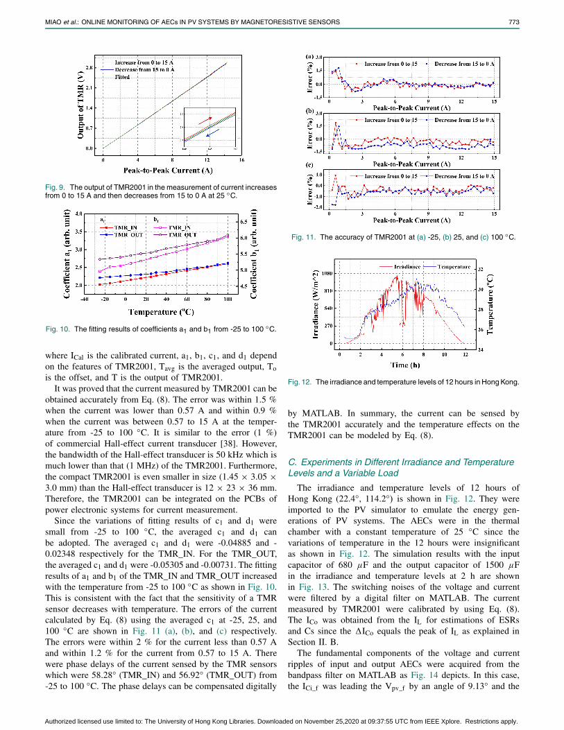
Fig. 9. The output of TMR2001 in the measurement of current increasesfrom 0 to 15 A and then decreases from 15 to 0 A at 25 ◦C.
Fig. 10. The fitting results of coefficients a1 and b1 from -25 to 100 ◦C.
where ICal is the calibrated current, a1, b1, c1, and d1 dependon the features of TMR2001, Tavg is the averaged output, Tois the offset, and T is the output of TMR2001.
It was proved that the current measured by TMR2001 can beobtained accurately from Eq. (8). The error was within 1.5 %when the current was lower than 0.57 A and within 0.9 %when the current was between 0.57 to 15 A at the temper-ature from -25 to 100 ◦C. It is similar to the error (1 %)of commercial Hall-effect current transducer [38]. However,the bandwidth of the Hall-effect transducer is 50 kHz which ismuch lower than that (1 MHz) of the TMR2001. Furthermore,the compact TMR2001 is even smaller in size (1.45 × 3.05 ×3.0 mm) than the Hall-effect transducer is 12 × 23 × 36 mm.Therefore, the TMR2001 can be integrated on the PCBs ofpower electronic systems for current measurement.
Since the variations of fitting results of c1 and d1 weresmall from -25 to 100 ◦C, the averaged c1 and d1 canbe adopted. The averaged c1 and d1 were -0.04885 and -0.02348 respectively for the TMR_IN. For the TMR_OUT,the averaged c1 and d1 were -0.05305 and -0.00731. The fittingresults of a1 and b1 of the TMR_IN and TMR_OUT increasedwith the temperature from -25 to 100 ◦C as shown in Fig. 10.This is consistent with the fact that the sensitivity of a TMRsensor decreases with temperature. The errors of the currentcalculated by Eq. (8) using the averaged c1 at -25, 25, and100 ◦C are shown in Fig. 11 (a), (b), and (c) respectively.The errors were within 2 % for the current less than 0.57 Aand within 1.2 % for the current from 0.57 to 15 A. Therewere phase delays of the current sensed by the TMR sensorswhich were 58.28◦ (TMR_IN) and 56.92◦ (TMR_OUT) from-25 to 100 ◦C. The phase delays can be compensated digitally
Fig. 11. The accuracy of TMR2001 at (a) -25, (b) 25, and (c) 100 ◦C.
Fig. 12. The irradiance and temperature levels of 12 hours in Hong Kong.
by MATLAB. In summary, the current can be sensed bythe TMR2001 accurately and the temperature effects on theTMR2001 can be modeled by Eq. (8).
C. Experiments in Different Irradiance and TemperatureLevels and a Variable Load
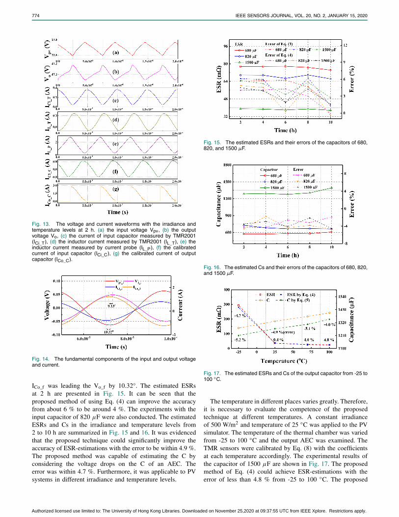
The irradiance and temperature levels of 12 hours ofHong Kong (22.4◦, 114.2◦) is shown in Fig. 12. They wereimported to the PV simulator to emulate the energy gen-erations of PV systems. The AECs were in the thermalchamber with a constant temperature of 25 ◦C since thevariations of temperature in the 12 hours were insignificantas shown in Fig. 12. The simulation results with the inputcapacitor of 680 μF and the output capacitor of 1500 μFin the irradiance and temperature levels at 2 h are shownin Fig. 13. The switching noises of the voltage and currentwere filtered by a digital filter on MATLAB. The currentmeasured by TMR2001 were calibrated by using Eq. (8).The ICo was obtained from the IL for estimations of ESRsand Cs since the �ICo equals the peak of IL as explained inSection II. B.
The fundamental components of the voltage and currentripples of input and output AECs were acquired from thebandpass filter on MATLAB as Fig. 14 depicts. In this case,the ICi_f was leading the Vpv_f by an angle of 9.13◦ and the
Authorized licensed use limited to: The University of Hong Kong Libraries. Downloaded on November 25,2020 at 09:37:55 UTC from IEEE Xplore. Restrictions apply.
774 IEEE SENSORS JOURNAL, VOL. 20, NO. 2, JANUARY 15, 2020
Fig. 13. The voltage and current waveforms with the irradiance andtemperature levels at 2 h. (a) the input voltage Vpv, (b) the outputvoltage Vo, (c) the current of input capacitor measured by TMR2001(ICi_T), (d) the inductor current measured by TMR2001 (IL_T), (e) theinductor current measured by current probe (IL_P), (f) the calibratedcurrent of input capacitor (ICi_C), (g) the calibrated current of outputcapacitor (ICo_C).
Fig. 14. The fundamental components of the input and output voltageand current.
ICo_f was leading the Vo_f by 10.32◦. The estimated ESRsat 2 h are presented in Fig. 15. It can be seen that theproposed method of using Eq. (4) can improve the accuracyfrom about 6 % to be around 4 %. The experiments with theinput capacitor of 820 μF were also conducted. The estimatedESRs and Cs in the irradiance and temperature levels from2 to 10 h are summarized in Fig. 15 and 16. It was evidencedthat the proposed technique could significantly improve theaccuracy of ESR-estimations with the error to be within 4.9 %.The proposed method was capable of estimating the C byconsidering the voltage drops on the C of an AEC. Theerror was within 4.7 %. Furthermore, it was applicable to PVsystems in different irradiance and temperature levels.
Fig. 15. The estimated ESRs and their errors of the capacitors of 680,820, and 1500 μF.
Fig. 16. The estimated Cs and their errors of the capacitors of 680, 820,and 1500 μF.
Fig. 17. The estimated ESRs and Cs of the output capacitor from -25 to100 ◦C.
The temperature in different places varies greatly. Therefore,it is necessary to evaluate the competence of the proposedtechnique at different temperatures. A constant irradianceof 500 W/m2 and temperature of 25 ◦C was applied to the PVsimulator. The temperature of the thermal chamber was variedfrom -25 to 100 ◦C and the output AEC was examined. TheTMR sensors were calibrated by Eq. (8) with the coefficientsat each temperature accordingly. The experimental results ofthe capacitor of 1500 μF are shown in Fig. 17. The proposedmethod of Eq. (4) could achieve ESR-estimations with theerror of less than 4.8 % from -25 to 100 ◦C. The proposed
Authorized licensed use limited to: The University of Hong Kong Libraries. Downloaded on November 25,2020 at 09:37:55 UTC from IEEE Xplore. Restrictions apply.
MIAO et al.: ONLINE MONITORING OF AECs IN PV SYSTEMS BY MAGNETORESISTIVE SENSORS 775
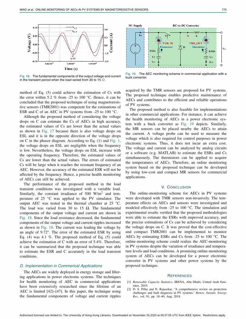
Fig. 18. The fundamental components of the output voltage and currentin the transient period when the load varied from 30 to 15 Ω.
method of Eq. (5) could achieve the estimation of Cs withthe error within 5.2 % from -25 to 100 ◦C. Hence, it can beconcluded that the proposed technique of using magnetoresis-tive sensors (TMR2001) was competent for the estimations ofESR and C of an AEC in PV systems from -25 to 100 ◦C.
Although the proposed method of considering the voltagedrops on C can estimate the Cs of AECs in high accuracy,the estimated values of Cs are lower than the actual valuesas shown in Fig. 17 because there is also voltage drops onESL and it is in the opposite direction of the voltage dropson C in the phasor diagram. According to Eq. (1) and Fig. 1,the voltage drops on ESL are negligible when the frequencyis low. Nevertheless, the voltage drops on ESL increase withthe operating frequency. Therefore, the estimated values ofCs are lower than the actual values. The errors of estimatedCs will be large when it reaches the resonant frequency of anAEC. However, the accuracy of the estimated ESR will not beaffected by the frequency. Hence, a precise health monitoringof AECs can still be achieved.
The performance of the proposed method in the loadtransient conditions was investigated with a variable load.Similarly, the constant irradiance of 500 W/m2 and tem-perature of 25 ◦C was applied to the PV simulator. Theoutput AEC was tested in the thermal chamber at 25 ◦C.The load was varied from 30 to 15 �. The fundamentalcomponents of the output voltage and current are shown inFig. 18. Since the load resistance decreased, the fundamentalcomponents of the output voltage and current ripples increasedas shown in Fig. 18. The current was leading the voltage byan angle of 9.72◦. The error of the estimated ESR by usingEq. (4) was 4.1 %. The proposed method of Eq. (5) couldachieve the estimation of C with an error of 5.4%. Therefore,it can be summarized that the proposed technique was ableto estimate the ESR and C accurately in the load transientconditions.
D. Implementation in Commerical Applications
The AECs are widely deployed in energy storage and filter-ing applications in power electronic systems. The techniquesfor health monitoring of AEC in commercial applicationshave been extensively researched since the lifetime of anAEC is limited [42]–[47]. In this paper, the technique usingthe fundamental components of voltage and current ripples
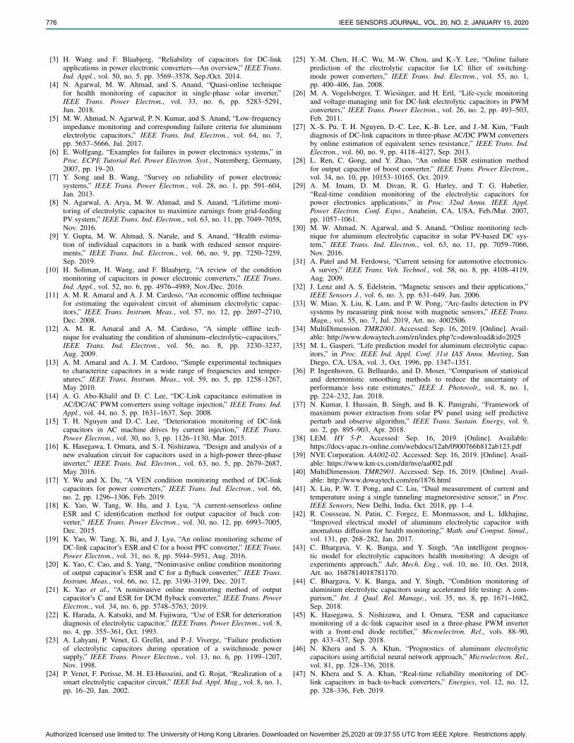
Fig. 19. The AEC monitoring scheme in commercial application with abuck converter.
acquired by the TMR sensors are proposed for PV systems.The proposed technique enables predictive maintenance ofAECs and contributes to the efficient and reliable operationsof PV systems.
The proposed method is also feasible for implementationsin other commercial applications. For instance, it can achievethe health monitoring of AECs in a power electronic sys-tem with a buck converter as Fig. 19 depicts. Similarly,the MR sensors can be placed nearby the AECs to attainthe current. A voltage probe can be used to measure thevoltage which is also required for control purposes in powerelectronic systems. Thus, it does not incur an extra cost.The voltage and current can be analyzed by analog circuitsor a software (e.g. MATLAB) to estimate the ESRs and Cssimultaneously. The thermistors can be applied to acquirethe temperatures of AECs. Therefore, an online monitoringsystem based on the proposed technique can be developedby using low-cost and compact MR sensors for commercialapplications.
V. CONCLUSION
The online-monitoring scheme for AECs in PV systemswere developed with TMR sensors non-invasively. The tem-perature effects on AECs and sensors were investigated andmodeled effectively from -25 to 100 ◦C. The simulation andexperimental results verified that the proposed methodologieswere able to estimate the ESRs with improved accuracy, andthe precise estimations of Cs can be achieved by consideringthe voltage drops on C. It was proved that the cost-effectiveand compact TMR2001 can be implemented to monitorAECs by estimating ESRs and Cs from -25 to 100 ◦C. Theonline-monitoring scheme could realize the AEC-monitoringin PV systems despite the variation of irradiance and tempera-ture levels and load conditions. A promising online-monitoringsystem of AECs can be developed for a power electronicconverter in PV systems and other power systems by theproposed technique.
REFERENCES
[1] Renewable Capacity Statistics, IRENA, Abu Dhabi, United Arab Emi-rates, 2019.
[2] D. S. Pillai and N. Rajasekar, “A comprehensive review on protectionchallenges and fault diagnosis in PV systems,” Renew. Sustain. EnergyRev., vol. 91, pp. 18–40, Aug. 2018.
Authorized licensed use limited to: The University of Hong Kong Libraries. Downloaded on November 25,2020 at 09:37:55 UTC from IEEE Xplore. Restrictions apply.
776 IEEE SENSORS JOURNAL, VOL. 20, NO. 2, JANUARY 15, 2020
[3] H. Wang and F. Blaabjerg, “Reliability of capacitors for DC-linkapplications in power electronic converters—An overview,” IEEE Trans.Ind. Appl., vol. 50, no. 5, pp. 3569–3578, Sep./Oct. 2014.
[4] N. Agarwal, M. W. Ahmad, and S. Anand, “Quasi-online techniquefor health monitoring of capacitor in single-phase solar inverter,”IEEE Trans. Power Electron., vol. 33, no. 6, pp. 5283–5291,Jun. 2018.
[5] M. W. Ahmad, N. Agarwal, P. N. Kumar, and S. Anand, “Low-frequencyimpedance monitoring and corresponding failure criteria for aluminumelectrolytic capacitors,” IEEE Trans. Ind. Electron., vol. 64, no. 7,pp. 5657–5666, Jul. 2017.
[6] E. Wolfgang, “Examples for failures in power electronics systems,” inProc. ECPE Tutorial Rel. Power Electron. Syst., Nuremberg, Germany,2007, pp. 19–20.
[7] Y. Song and B. Wang, “Survey on reliability of power electronicsystems,” IEEE Trans. Power Electron., vol. 28, no. 1, pp. 591–604,Jan. 2013.
[8] N. Agarwal, A. Arya, M. W. Ahmad, and S. Anand, “Lifetime moni-toring of electrolytic capacitor to maximize earnings from grid-feedingPV system,” IEEE Trans. Ind. Electron., vol. 63, no. 11, pp. 7049–7058,Nov. 2016.
[9] Y. Gupta, M. W. Ahmad, S. Narale, and S. Anand, “Health estima-tion of individual capacitors in a bank with reduced sensor require-ments,” IEEE Trans. Ind. Electron., vol. 66, no. 9, pp. 7250–7259,Sep. 2019.
[10] H. Soliman, H. Wang, and F. Blaabjerg, “A review of the conditionmonitoring of capacitors in power electronic converters,” IEEE Trans.Ind. Appl., vol. 52, no. 6, pp. 4976–4989, Nov./Dec. 2016.
[11] A. M. R. Amaral and A. J. M. Cardoso, “An economic offline techniquefor estimating the equivalent circuit of aluminum electrolytic capac-itors,” IEEE Trans. Instrum. Meas., vol. 57, no. 12, pp. 2697–2710,Dec. 2008.
[12] A. M. R. Amaral and A. M. Cardoso, “A simple offline tech-nique for evaluating the condition of aluminum–electrolytic–capacitors,”IEEE Trans. Ind. Electron., vol. 56, no. 8, pp. 3230–3237,Aug. 2009.
[13] A. M. Amaral and A. J. M. Cardoso, “Simple experimental techniquesto characterize capacitors in a wide range of frequencies and temper-atures,” IEEE Trans. Instrum. Meas., vol. 59, no. 5, pp. 1258–1267,May 2010.
[14] A. G. Abo-Khalil and D. C. Lee, “DC-Link capacitance estimation inAC/DC/AC PWM converters using voltage injection,” IEEE Trans. Ind.Appl., vol. 44, no. 5, pp. 1631–1637, Sep. 2008.
[15] T. H. Nguyen and D.-C. Lee, “Deterioration monitoring of DC-linkcapacitors in AC machine drives by current injection,” IEEE Trans.Power Electron., vol. 30, no. 3, pp. 1126–1130, Mar. 2015.
[16] K. Hasegawa, I. Omura, and S.-I. Nishizawa, “Design and analysis of anew evaluation circuit for capacitors used in a high-power three-phaseinverter,” IEEE Trans. Ind. Electron., vol. 63, no. 5, pp. 2679–2687,May 2016.
[17] Y. Wu and X. Du, “A VEN condition monitoring method of DC-linkcapacitors for power converters,” IEEE Trans. Ind. Electron., vol. 66,no. 2, pp. 1296–1306, Feb. 2019.
[18] K. Yao, W. Tang, W. Hu, and J. Lyu, “A current-sensorless onlineESR and C identification method for output capacitor of buck con-verter,” IEEE Trans. Power Electron., vol. 30, no. 12, pp. 6993–7005,Dec. 2015.
[19] K. Yao, W. Tang, X. Bi, and J. Lyu, “An online monitoring scheme ofDC-link capacitor’s ESR and C for a boost PFC converter,” IEEE Trans.Power Electron., vol. 31, no. 8, pp. 5944–5951, Aug. 2016.
[20] K. Yao, C. Cao, and S. Yang, “Noninvasive online condition monitoringof output capacitor’s ESR and C for a flyback converter,” IEEE Trans.Instrum. Meas., vol. 66, no. 12, pp. 3190–3199, Dec. 2017.
[21] K. Yao et al., “A noninvasive online monitoring method of outputcapacitor’s C and ESR for DCM flyback converter,” IEEE Trans. PowerElectron., vol. 34, no. 6, pp. 5748–5763, 2019.
[22] K. Harada, A. Katsuki, and M. Fujiwara, “Use of ESR for deteriorationdiagnosis of electrolytic capacitor,” IEEE Trans. Power Electron., vol. 8,no. 4, pp. 355–361, Oct. 1993.
[23] A. Lahyani, P. Venet, G. Grellet, and P.-J. Viverge, “Failure predictionof electrolytic capacitors during operation of a switchmode powersupply,” IEEE Trans. Power Electron., vol. 13, no. 6, pp. 1199–1207,Nov. 1998.
[24] P. Venet, F. Perisse, M. H. El-Husseini, and G. Rojat, “Realization of asmart electrolytic capacitor circuit,” IEEE Ind. Appl. Mag., vol. 8, no. 1,pp. 16–20, Jan. 2002.
[25] Y.-M. Chen, H.-C. Wu, M.-W. Chou, and K.-Y. Lee, “Online failureprediction of the electrolytic capacitor for LC filter of switching-mode power converters,” IEEE Trans. Ind. Electron., vol. 55, no. 1,pp. 400–406, Jan. 2008.
[26] M. A. Vogelsberger, T. Wiesinger, and H. Ertl, “Life-cycle monitoringand voltage-managing unit for DC-link electrolytic capacitors in PWMconverters,” IEEE Trans. Power Electron., vol. 26, no. 2, pp. 493–503,Feb. 2011.
[27] X.-S. Pu, T. H. Nguyen, D.-C. Lee, K.-B. Lee, and J.-M. Kim, “Faultdiagnosis of DC-link capacitors in three-phase AC/DC PWM convertersby online estimation of equivalent series resistance,” IEEE Trans. Ind.Electron., vol. 60, no. 9, pp. 4118–4127, Sep. 2013.
[28] L. Ren, C. Gong, and Y. Zhao, “An online ESR estimation methodfor output capacitor of boost converter,” IEEE Trans. Power Electron.,vol. 34, no. 10, pp. 10153–10165, Oct. 2019.
[29] A. M. Imam, D. M. Divan, R. G. Harley, and T. G. Habetler,“Real-time condition monitoring of the electrolytic capacitors forpower electronics applications,” in Proc. 32nd Annu. IEEE Appl.Power Electron. Conf. Expo., Anaheim, CA, USA, Feb./Mar. 2007,pp. 1057–1061.
[30] M. W. Ahmad, N. Agarwal, and S. Anand, “Online monitoring tech-nique for aluminum electrolytic capacitor in solar PV-based DC sys-tem,” IEEE Trans. Ind. Electron., vol. 63, no. 11, pp. 7059–7066,Nov. 2016.
[31] A. Patel and M. Ferdowsi, “Current sensing for automotive electronics-A survey,” IEEE Trans. Veh. Technol., vol. 58, no. 8, pp. 4108–4119,Aug. 2009.
[32] J. Lenz and A. S. Edelstein, “Magnetic sensors and their applications,”IEEE Sensors J., vol. 6, no. 3, pp. 631–649, Jun. 2006.
[33] W. Miao, X. Liu, K. Lam, and P. W. Pong, “Arc-faults detection in PVsystems by measuring pink noise with magnetic sensors,” IEEE Trans.Magn., vol. 55, no. 7, Jul. 2019, Art. no. 4002506.
[34] MultiDimension. TMR2001. Accessed: Sep. 16, 2019. [Online]. Avail-able: http://www.dowaytech.com/en/index.php?c=download&id=2025
[35] M. L. Gasperi, “Life prediction model for aluminum electrolytic capac-itors,” in Proc. IEEE Ind. Appl. Conf. 31st IAS Annu. Meeting, SanDiego, CA, USA, vol. 3, Oct. 1996, pp. 1347–1351.
[36] P. Ingenhoven, G. Belluardo, and D. Moser, “Comparison of statisticaland deterministic smoothing methods to reduce the uncertainty ofperformance loss rate estimates,” IEEE J. Photovolt., vol. 8, no. 1,pp. 224–232, Jan. 2018.
[37] N. Kumar, I. Hussain, B. Singh, and B. K. Panigrahi, “Framework ofmaximum power extraction from solar PV panel using self predictiveperturb and observe algorithm,” IEEE Trans. Sustain. Energy, vol. 9,no. 2, pp. 895–903, Apr. 2018.
[38] LEM. HY 5-P. Accessed: Sep. 16, 2019. [Online]. Available:https://docs-apac.rs-online.com/webdocs/12ab/0900766b812ab123.pdf
[39] NVE Corporation. AA002-02. Accessed: Sep. 16, 2019. [Online]. Avail-able: https://www.km-cs.com/dir/nve/aa002.pdf
[40] MultiDimension. TMR2901. Accessed: Sep. 16, 2019. [Online]. Avail-able: http://www.dowaytech.com/en/1876.html
[41] X. Liu, P. W. T. Pong, and C. Liu, “Dual measurement of current andtemperature using a single tunneling magnetoresistive sensor,” in Proc.IEEE Sensors, New Delhi, India, Oct. 2018, pp. 1–4.
[42] R. Cousseau, N. Patin, C. Forgez, E. Monmasson, and L. Idkhajine,“Improved electrical model of aluminum electrolytic capacitor withanomalous diffusion for health monitoring,” Math. and Comput. Simul.,vol. 131, pp. 268–282, Jan. 2017.
[43] C. Bhargava, V. K. Banga, and Y. Singh, “An intelligent prognos-tic model for electrolytic capacitors health monitoring: A design ofexperiments approach,” Adv. Mech. Eng., vol. 10, no. 10, Oct. 2018,Art. no. 1687814018781170.
[44] C. Bhargava, V. K. Banga, and Y. Singh, “Condition monitoring ofaluminium electrolytic capacitors using accelerated life testing: A com-parison,” Int. J. Qual. Rel. Manage., vol. 35, no. 8, pp. 1671–1682,Sep. 2018.
[45] K. Hasegawa, S. Nishizawa, and I. Omura, “ESR and capacitancemonitoring of a dc-link capacitor used in a three-phase PWM inverterwith a front-end diode rectifier,” Microelectron. Rel., vols. 88–90,pp. 433–437, Sep. 2018.
[46] N. Khera and S. A. Khan, “Prognostics of aluminum electrolyticcapacitors using artificial neural network approach,” Microelectron. Rel.,vol. 81, pp. 328–336, 2018.
[47] N. Khera and S. A. Khan, “Real-time reliability monitoring of DC-link capacitors in back-to-back converters,” Energies, vol. 12, no. 12,pp. 328–336, Feb. 2019.
Authorized licensed use limited to: The University of Hong Kong Libraries. Downloaded on November 25,2020 at 09:37:55 UTC from IEEE Xplore. Restrictions apply.
MIAO et al.: ONLINE MONITORING OF AECs IN PV SYSTEMS BY MAGNETORESISTIVE SENSORS 777
Wenchao Miao received the B.Eng. degree inelectrical and electronic engineering from theUniversity of Nottingham, U.K. He is currentlypursuing the Ph.D. degree with the Departmentof Electrical and Electronic Engineering, TheUniversity of Hong Kong, Hong Kong. His cur-rent research interests include the applicationsof magnetoresistive sensors in power systems,faults detection in DC systems, and the conditionmonitoring of photovoltaic systems.
K. H. Lam received the bachelor’s degree inelectrical energy systems engineering and thePh.D. degree in architecture from The Univer-sity of Hong Kong, Hong Kong, in 1994 and2007, respectively. He was with the buildingservices industry after graduation and returnedto his Alma Mater, joined the HKU PhotovoltaicResearch Team, in 1998. He started to work asa Senior Manager with Solar Energy Company.From 2008 to 2009, he was the Chairman of theHong Kong Photovoltaic Consortium. In 2014,
he was appointed as a Lecturer with the Department of Electricaland Electronic Engineering, The University of Hong Kong, where hebecame an Honorary Assistant Professor in 2016. He is a Lecturer withThe University of Hong Kong. His current research interest includesphotovoltaic systems integration. He is also a Registered CharteredElectrical Engineer with the Engineering Council, U.K., and a RegisteredEnergy Assessor with the Hong Kong Government.
Philip W. T. Pong (SM’13) received the Ph.D.degree in engineering from the Universityof Cambridge in 2005. After working as aPost-Doctoral Researcher with the MagneticMaterials Group, National Institute of Standardsand Technology (NIST), USA, for three years,he joined the Department of Electrical andElectronic Engineering (EEE), The University ofHong Kong (HKU), Hong Kong, where he iscurrently a tenured Associate Professor workingon development and the applications of magne-
toresistive sensors and contactless sensing technologies in smart gridand smart living. He has published more than 120 SCI journal papers witharound 1700 citations. His current research interests include magnetore-sistive sensors and smart grid. He is a fellow of the Institution of Engineer-ing and Technology (FIET), the Institute of Materials, Minerals and Mining(FIMMM), the Energy Institute (FEI), and the NANOSMAT Society (FNS).He is a Corporate Member of HKIE in electrical, electronics, and energydivisions. He serves on the Editorial Board for two SCI journals and onthe Editorial Review Board of the IEEE MAGNETICS LETTERS. He is alsoa Chartered Physicist, a Chartered Electrical Engineer, and a CharteredEnergy Engineer. He is a Registered Professional Engineer of Electrical,Electronics, and Energy in Hong Kong. From 2019 to 2022, he was theACM Distinguished Speaker on the topic of contactless sensing andsmart living.
Authorized licensed use limited to: The University of Hong Kong Libraries. Downloaded on November 25,2020 at 09:37:55 UTC from IEEE Xplore. Restrictions apply.