alexander heldring, and eduard ubeda a microwave
TRANSCRIPT

IEEE P
roof
2 IEEE ANTENNAS & PROPAGATION MAGAZINE A U G U S T 2 0 1 81045-9243/18©2018IEEE
Pedro Yuste, Juan M. Rius, Jordi Romeu, Sebastián Blanch, Alexander Heldring, and Eduard Ubeda
A Microwave Invisibility CloakThe design, simulation, and measurement of a simple and effective frequency-selective surface-based mantle cloak.
<AU: Please check whether the edited title and added subtitle are acceptable.>
XXXXXX
In recent years, there has been a growing interest in developing invisibility cloaks that can conceal an object. These techniques are often based either on coating a dielectric or conducting object with a homogeneous plasmonic layer of negative per-
mittivity [1] or on a creating multilayer structure [2] that cancels the scattering of the cloaked object (i.e., scattering cancelation technique). <AU: Please check whether the preceding edited sentence conveys the intended meaning.> The technique may also be based on an inhomogeneous layer that bends electromagnetic waves around the region occupied by the cloaked object without interacting with it (i.e., transformation optics technique) [3].
Plasmonic- and transformation-based cloaks require mate-rials of constituent properties not found in nature. The use of metamaterials made of lattices of subwavelength details [4], [5] achieves nonphysical values of dielectric permittivity and magnetic permeability, allowing the practical implementation of such cloaks in the microwave frequency band that is of interest here [6], [7].
An alternate approach is to optimize the cloak parameters to minimize scattering [8]–[11]. When the coating consists only of isotropic nonmagnetic dielectrics, the graded refraction index
is physically realizable by varying doping profiles or nanoper-foration [9], [10]. Transformation-based and plasmonic cloaks have important handicaps, such as bulky metamaterial layers, narrow bandwidth, sensitivity, and difficult implementation of the inhomogeneous refraction index profile or the negative con-stitutive parameters. The use of a frequency-selective surface (FSS) [12] as a mantle coat to achieve scattering cancelation [13], [14] allows for the easy building of a cloak for electrically thin cylinders using a simple, ultrathin, patterned conducting surface with important practical advantages, such as having a low pro-file, being lightweight, and having a broader band of operation. An excellent review of cloaking history and a summary of the scattering cancelation technique for both plasmonic and mantle cloaks can be found in [15].
Reducing forward scattering from electrically thin cylinders was first addressed by Kildal in the 1990s [16] by using the con-cept of hard and soft surfaces [17]. The topic is still under active research, using either hard surfaces [18] or FSS mantle cloaks [19]–[21]. <AU: Please check whether the preceding edited sentence conveys the intended meaning.> Recent advances include the ability to cloak the cylinder at both polarizations [22] using anisotropic FSS [23].
An FSS is probably the most cost-effective and easiest-to-implement choice for putting scattering cancelation into prac-tice. The electromagnetic behavior of an FSS can be described
Digital Object Identifier 10.1109/MAP.2018.2839903Date of publication: xxxxxx

IEEE P
roof
3IEEE ANTENNAS & PROPAGATION MAGAZINE A U G U S T 2 0 1 8
by means of surface impedance; hence, ,Zs which relates the averaged tangential electric field on the surface to the averaged induced electric current density:
,E JZt s s$= (1)
,H H Jn sout in# - =t ^ h (2)
where Hout is the magnetic field in the outer face of the FSS and Hin is the magnetic field in the inner face. The average surface impedance Zs is ideally assumed uniform along the metasurface.
The geometry of an FSS cloak, consisting of a very thin metallic layer, can be designed to implement the average surface impedance that minimizes the scattered field. Moreover, at microwave frequencies, the FSS can be assumed lossless; thus, its average surface impedance is purely reactive, ,Z jXs s= if the power dissipated at the FSS is zero:
( )
.
H H
H H
P P
Z
E
0t t t
s t t2
out in out in
out in
#0
0
- = -
= - =
)66 @
@
(3)
Although the scattering cancelation technique and the design of FSS mantle cloaks have been fully addressed in the literature, the complete presentation of theory development, design procedure, simulation techniques, prototype building, and measurement results is scattered among many books and articles, leading the novice practitioner to leap from one source to another to get the overall picture. The aim of this article is to didactically present the complete process, letting readers repro-duce it and easily build a simple and inexpensive cloak like that of [19]. In particular, the derivation of the scattering coefficients in (15) is fully developed in the section “Mantle Cloaking Fun-damentals” because it cannot be found in the references cited here or in the references cited by the literature. <AU: Please check whether the preceding edited sentence conveys the intended meaning.> Although some books derive the scatter-ing coefficients for bare dielectric cylinders, we have not found the derivation given here for the coated case.
MANTLE CLOAKING FUNDAMENTALSConsider the scenario presented in Figure 1. A circular cylinder of radius ,a dielectric permittivity equal to ,1f and magnetic permeability equal to 1n was coated with a zero-thickness sur-face of impedance Zs (i.e., the cloak), located at .at = For practical purposes, we consider a nonmagnetic cylinder of
.1 0n n= The value of the coat surface impedance Zs was designed to achieve cancelation between the scattering from the bare dielectric cylinder and that from the coat.
Let us assume a TMz-polarized <AU: Kindly spell out TMz.> impinging plane wave propagating along the x axis,
,E e E eE z z cosi jk x jk0 0
0 0= = t z- -t t (4)
where e jwt harmonic time variation is assumed. According to the Jacobi-Anger expansion, the plane wave can be expressed in terms of cylindrical harmonics as [25]
.E j J k eE zi n
nn
jn0 0t=
3
3z-
=-
t ^ h/ (5)
Similarly, the cylindrical wave expansion for the scattered elec-tric field outside the dielectric cylinder is
,E E a H k eE z z ( )szs
nn
njn
02
0t= =3
3z
=-
t t ^ h/ (6)
where an is the scattering coefficient and H( )n2 is the Hankel
function of the second kind [25] that represents outward travel-ing cylindrical waves.
The total electric field inside the cylinder is expanded in cylindrical harmonics as
,E b J k eE z nn
njn
0 1in t=
3
3z
=-
t ^ h/ (7)
where bn is the coefficient of the cylindrical modes inside the dielectric. Outside the cylinder, the total field is
.E E Es iout = + (8)
The magnetic-field boundary condition at the coating layer, ,at = for the layout of Figure 1 is
,H H J ZEn z za z a s
z
a
out in# z- = =z z t tt
= ==
t tt t^ h (9)
where Zs is the coat surface impedance and nt the unit normal to the surface.
The magnetic field inside and outside the cylinder was obtained from the electric field (7) and (8) after applying Max-well-Faraday curl equation:
magnetic field inside ( ):a1t
,JH jk b k k e1nn
n
jn
1 11 1
in
ht=
3
3
zz
=-
l ^ h/ (10)
magnetic field outside ( ):a2t
,
H jk j k J k
a k H k e
1 nn
n
n njn
0 00 0
0 02
out
ht
t
= +
+
3
3
z
z
-
=-
l
l
^
^^
h
hh
6
@
/
(11)
E0e–jk0x
P0 µ0
µ1 P1
k1
k0
a
Zs
ρ
φx
"
y
"
FIGURE 1. A geometrical layout of the dielectric cylinder (in yellow) and the cloak (in red).

IEEE P
roof
4 IEEE ANTENNAS & PROPAGATION MAGAZINE A U G U S T 2 0 1 8
where the prime symbol denotes the derivative with respect to the argument of Bessel functions [25].
Since (9) states that ( )E Z H Hz sout in= -z z at ,at =
.
E jk Z j k J k a a Z k H k a
jk b Z k J k a e
1
1
z sn
n n s nn
n s njn
0 00 0 0 0
1 11 1
2
h
h
= +
-
3
3
z
-
=-
l l
l ^
^ ^
^
^ ^
h
h h
h
hh;
E
/
(12)
According to the boundary condition for the electric field )(E E 0z z a
out in- =t= and using (8) together with the cylindrical mode expansions (6) and (7),
.
E j J k a a H k a e
b J k a e
( )z
nn n n
n
jn
nn
njn
02
0
1
= +
=
3
3
3
3
z
z
-
=-
=-
^
^ ^
h
h h6 @/
/
(13)
The combination of (12) and (13) easily leads to the following system of equations:
.
H k a
j Z H k a
J k a
j Z J k a J k a
ab
j J k a
j j Z J k a
1 1
1
( )
( )
n
s n
n
s n n
n
n
nn
ns n
20
0
20
1
11 1
0
00
h h
h
-
- -
=-
-
-
-
l l
l
^
^
^
^
^
^
^f
c f
h
h
h
h
h
h
h
m p
p
(14)
The solution for the scattering coefficients an using Cramer’s rule is
,aH k a
Z H k aJ k a
n Z J k a j J k a
jJ k aZ J k a
J k an Z J k a j J k a
( )
( )
nn
s
n
s n n
n n
s
n
s n n
n
n
20
20
1
1 1 0 1
0
0
1
1 1 0 1
h
h=
-
- -
--
l l
l l
^
^
^
^ ^
^
^
^
^
^
h
h
h
h h
h
h
h
h
h
(15)
where ( / ) .( / )n1 0 1 1 0h h f f= =
Because we have only one degree of freedom, ,Zs only a sin-gle cylindrical harmonic of the scattered field can be zeroed to minimize scattering. If the cylinder is electrically thin, ,a % m
the dominant harmonic is the lowest order, and, therefore, we design Zs to achieve :a 00 =
,Z jX jn J k a J k a J k a J k a
J k a J k as s
1 0 0 1 1 1 0 0 1
0 0 0 0 1h= =
-^ ^
^ ^
^ ^h h
h h
h h (16)
where we have used the identity ( ) ( )J ka J ka0 1=-l [25] to remove the derivatives. For electrically wider cylinders, ~ ,a0 m we could consider minimizing the square sum of the lowest-order coefficients a a0
21
2f+ + instead of forcing .a 00 =
This result gave the surface reactance of the cloaking coat attached to an electrically thin cylinder that minimized the scattered field and, thus, reduced its visibility. The polyvinyl chloride (PVC) cylinder to coat here had dielectric permittivity
. ,2 723rf = measured with the waveguide method [26], and a radius . .a 1 34 cm= At the design frequency of 3.77 GHz, the required coat impedance was . .Z j192 5s X=
The coat was implemented with an FSS [12]. One of the sim-plest and easiest-to-build FSS designs is the mesh grid shown in Figure 2. For this metasurface, the equivalent surface imped-ance Zs depended on geometrical dimensions as follows, for the TM-polarized <AU: Kindly spell out TM.> case [27]:
,ln csc sinZ j DDw
4 1 1sTM
r
s0
2
fhm
r i= -
+` ` cjj m (17)
where D is the mesh period, w the strip width, / ,c 3 10 m s8$= and si is the angle of incidence. <AU: Kindly check that the preceding edited sentence conveys the intended mean-ing.>
To obtain a surface reactance of .192 5X at 3.77 GHz for normal incidence / ,2si r= the period and strip width of the mesh-grid FSS cells are .D 2 1 cm= and . ,w 1 9 mm= respec-tively.
NUMERICAL SIMULATIONThe simulation model is a replica of the PVC cylinder to be cloaked and measured, but it is shorter in length. It was a 33.6-cm-long circular cylinder with radius . .a 1 34 cm= Rela-tive permittivity of the dielectric material (i.e., PVC) was experi-mentally measured with the waveguide method and found to be
. .2 723rf =
The incoming TMz-polarized plane wave impinged per-pendicularly to the cylinder axis, oriented parallel to the z-axis, with the angle of incidence ( / ).2ii r= The FSS mesh-grid dimensions (Figure 2) were .D 2 1 cm= and . .w 1 9 mm= The copper grid was modeled as an infinitely thin surface of conduc-tivity equal to .m60 106 1 1$ X- - The dielectric cylinder and coat model was centered at the coordinate origin.
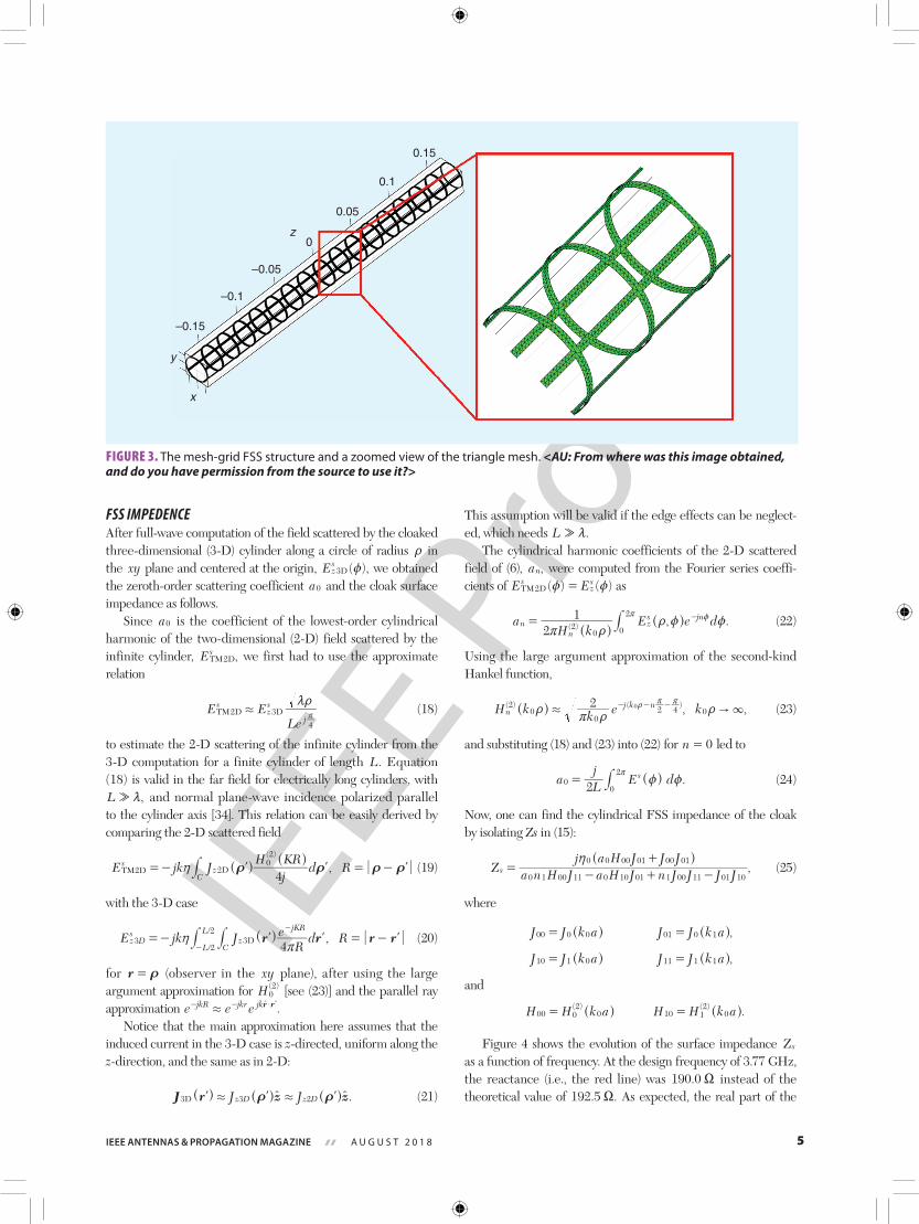
The cloak metasurface was meshed into RWG <AU: Kindly spell out RWG.> basis functions [28] (Figure 3) and the dielec-tric cylinder into pairs of tetrahedrons [29]. The problem was modeled with the surface-volume [30] electric field integral equation [31] and discretized by the method of moments [32]. The numerical code used was called fast integral equation solver for scatterers and antennas in three dimensions (FIESTA-3-D) [33], a software package developed at the AntennaLab of the Universitat Politècnica de Catalunya.
D
W
y
x x y
z
Pr
θi
FIGURE 2. The mesh-grid FSS geometry. <AU: From where was this image obtained, and do you have permission from the source to use it?>
IEEE P
roof
5IEEE ANTENNAS & PROPAGATION MAGAZINE A U G U S T 2 0 1 8
FSS IMPEDENCEAfter full-wave computation of the field scattered by the cloaked three-dimensional (3-D) cylinder along a circle of radius t in the xy plane and centered at the origin, ( ),Ez
s3D z we obtained
the zeroth-order scattering coefficient a0 and the cloak surface impedance as follows.
Since a0 is the coefficient of the lowest-order cylindrical harmonic of the two-dimensional (2-D) field scattered by the infinite cylinder, ,Es
2TM D we first had to use the approximate relation
E ELe
szs
j2 3
4
TM D D.mtr
(18)
to estimate the 2-D scattering of the infinite cylinder from the 3-D computation for a finite cylinder of length .L Equation (18) is valid in the far field for electrically long cylinders, with
,L & m and normal plane-wave incidence polarized parallel to the cylinder axis [34]. This relation can be easily derived by comparing the 2-D scattered field
,jKR
E jk JH
d R4
( )s
zC
2202
DTM D t tt th= - = -l l l^^
hh# (19)
with the 3-D case
,E jk JR
e d Rr r r r4/
/Dz
sz
CL
L jKR
3 32
2Dh
r= - = -
-
-
l l l^ h## (20)
for r t= (observer in the xy plane), after using the large argument approximation for H( )
02 [see (23)] and the parallel ray
approximation .e e ejkR jkr jkr r. $- - lt
Notice that the main approximation here assumes that the induced current in the 3-D case is z-directed, uniform along the z-direction, and the same as in 2-D:
J JJ r z z.z z33D 2D D. .t tl l lt t^ ^ ^h h h (21)
This assumption will be valid if the edge effects can be neglect-ed, which needs .L & m
The cylindrical harmonic coefficients of the 2-D scattered field of (6), ,an were computed from the Fourier series coeffi-cients of ( ) ( )E Es
zs
2TM D z z= as
, .aH k
E e d2
1( )nn
zs jn
20 0
2
r tt z z=
r z-
^^
hh# (22)
Using the large argument approximation of the second-kind Hankel function,
, ,H k k e k2( ) ( )n
j k n20
02 4 0
0 " 3.tr t
tt r r- - -^ h (23)
and substituting (18) and (23) into (22) for n 0= led to
.a Lj
E d2s
00
2z z=
r^ h# (24)
Now, one can find the cylindrical FSS impedance of the cloak by isolating Zs in (15):
,Z a n H J a H J n J J J Jj a H J J J
s0 1 00 11 0 10 01 1 00 11 01 10
0 0 00 01 00 01h=
- + -
+^ h (25)
where
,J J k a J J k a00 0 0 01 0 1= =^ ^h h
,J J k a J J k a10 1 0 11 1 1= =^ ^h h
and
.H H k a H H k a( ) ( )00 0
20 10 1
20= =^ ^h h
Figure 4 shows the evolution of the surface impedance Zs as a function of frequency. At the design frequency of 3.77 GHz, the reactance (i.e., the red line) was .190 0X instead of the theoretical value of . .192 5X As expected, the real part of the
–0.15
–0.1
–0.05
0
0.05
0.1
0.15
z
y
x
FIGURE 3. The mesh-grid FSS structure and a zoomed view of the triangle mesh. <AU: From where was this image obtained, and do you have permission from the source to use it?>

IEEE P
roof
6 IEEE ANTENNAS & PROPAGATION MAGAZINE A U G U S T 2 0 1 8
surface impedance was much smaller than the reactance (i.e., the green line).
It is interesting to compare the computed surface impedance for the cylindrical FSS with the required reactance for ideal cloaking from (16) (i.e., the blue line in Figure 4). The two lines cross each other at 3.78 GHz with an almost-zero resistance at that frequency. Therefore, the cloak is expected to work success-fully at a frequency of 3.78 instead of 3.77 GHz.
We can also compare this with the surface impedance of the planar infinite mesh grid, for which (17), used to design the cell dimensions, is valid. Infinite planar periodic structures can be
easily analyzed using Floquet mode theory from the simulation of a single cell. Since Floquet modes were not implemented in the FIESTA-3-D code, computer simulation technology (CST) was used [35]. In the CST, two Floquet ports were placed at both sides of a mesh-grid cell and computed S-parameters. The FSS impedance, ,Zs was related to parameter S11 using the equivalent transmission line model of Figure 5:
,Z Z SS
21
s 011
11
cell
cell=-+
c m (26)
where ,S S e( / )j d11 11
2cell port= r m with d being the length of the
transmission line from the Floquet port to the FSS plane and S11port being the reflection coefficient computed by CST at the ports. The black line in Figure 4 shows the reactance computed for the infinite planar mesh-grid FSS. The real part Rs is zero at all frequencies, since Zs is purely reactive in the ideal case.
The planar FSS reactance at the design frequency (i.e., .184 9X at 3.77 GHz) was very close to the value obtained
by the full-wave 3-D simulation of the cylindrical FSS (i.e., . ).190 0X This suggests that the mesh-grid geometry was cor-
rectly designed and the bending of the FSS in a curved surface did not significantly change the surface impedance near 3.77 GHz.
There are frequencies at which the surface reactance of the cylindrical FSS departed from the value for the infinite planar mesh grid computed by CST, having a very significant real part that ideally should be zero. This behavior resembles a kind of resonance specific to the cylindrical case and suggests that there are frequencies at which the design of the cloak using (17), valid for the planar case, may not work as expected.
FULL-WAVE SIMULATION OF MANTLE CLOAKING To assess cloaking performance, we simulated the bare dielec-tric cylinder and the cloaked one with FIESTA-3-D [33].
Frequency (GHz)
–50–25
0255075
100125150175200225250
Zs
(Ω)
Cylindrical FSS Surface Impedance
3.77 GHz
Real (Zs)Imaginary (Zs)
Xs CloakingXs Planar Mesh Grid
190
190.5
191
191.5
192
192.5
193
2.25 2.5 2.75 3 3.25 3.5 3.75 4 4.25 4.5 4.75 5
3.76 3.77 3.78 3.79
FIGURE 4. The simulated surface impedance of the cylindrical FSS as a function of frequency (real part Rs in green and imaginary part Xs in red), together with the reactance of the infinite planar mesh-grid FSS determined using computer-simulated technology software (in black) and the required reactance for ideal cloaking from (16) in blue. The cylindrical FSS reactance at the 3.77-GHz design frequency is .190 0X instead of the theoretical value of .192 5X and achieves the required reactance for ideal cloaking at a frequency of 3.78 GHz with an almost-zero resistance at that frequency.
Port 1
Port 1
Port 2
Port 2
UnitCell
E0e–jk0x
I→
Z0 = 120 π Ω Z0 = 120 π ΩZs
d = λ /4 d = λ /4
FIGURE 5. A transmission line model for an FSS of impedance Zs and normal incident plane wave.
Frequency (GHz)
Far-Field Sum (Es) for All Azimuth Angles
–55
–50
–45
–40
–35
–30
–25
–20
–15
Bare Cylinder Coated Cylinder
| Es |
(dB
)
2 2.5 3 3.5 4 4.5 5 5.5
FIGURE 6. The integration of ( )Es z for z as a function of frequency for the bare dielectric cylinder (blue line) and the coated cylinder (red line).
IEEE P
roof
7IEEE ANTENNAS & PROPAGATION MAGAZINE A U G U S T 2 0 1 8
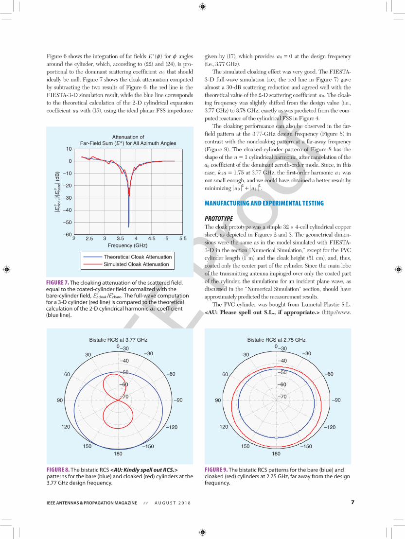
Figure 6 shows the integration of far fields ( )Es z for z angles around the cylinder, which, according to (22) and (24), is pro-portional to the dominant scattering coefficient a0 that should ideally be null. Figure 7 shows the cloak attenuation computed by subtracting the two results of Figure 6: the red line is the FIESTA-3-D simulation result, while the blue line corresponds to the theoretical calculation of the 2-D cylindrical expansion coefficient a0 with (15), using the ideal planar FSS impedance
given by (17), which provides a 00 = at the design frequency (i.e., 3.77 GHz).
The simulated cloaking effect was very good. The FIESTA-3-D full-wave simulation (i.e., the red line in Figure 7) gave almost a 30-dB scattering reduction and agreed well with the theoretical value of the 2-D scattering coefficient .a0 The cloak-ing frequency was slightly shifted from the design value (i.e., 3.77 GHz) to 3.78 GHz, exactly as was predicted from the com-puted reactance of the cylindrical FSS in Figure 4.
The cloaking performance can also be observed in the far-field pattern at the 3.77-GHz design frequency (Figure 8) in contrast with the noncloaking pattern at a far-away frequency (Figure 9). The cloaked-cylinder pattern of Figure 8 has the shape of the n 1= cylindrical harmonic, after cancelation of the a0 coefficient of the dominant zeroth-order mode. Since, in this case, .k a 1 751 = at 3.77 GHz, the first-order harmonic a1 was not small enough, and we could have obtained a better result by minimizing .a a0
21
2+
MANUFACTURING AND EXPERIMENTAL TESTING
PROTOTYPEThe cloak prototype was a simple 32 × 4-cell cylindrical copper sheet, as depicted in Figures 2 and 3. The geometrical dimen-sions were the same as in the model simulated with FIESTA-3-D in the section “Numerical Simulation,” except for the PVC cylinder length (1 m) and the cloak height (51 cm), and, thus, coated only the center part of the cylinder. Since the main lobe of the transmitting antenna impinged over only the coated part of the cylinder, the simulations for an incident plane wave, as discussed in the “Numerical Simulation” section, should have approximately predicted the measurement results.
The PVC cylinder was bought from Lumetal Plastic S.L. <AU: Please spell out S.L., if appropriate.> (http://www.
–60
–50
–40
–30
–20
–10
0
10
Theoretical Cloak AttenuationSimulated Cloak Attenuation
| Ecl
oak| /|
Eba
re| (
dB)
ss
Frequency (GHz)2 2.5 3 3.5 4 4.5 5 5.5
Attenuation ofFar-Field Sum (Es) for All Azimuth Angles
FIGURE 7. The cloaking attenuation of the scattered field, equal to the coated-cylinder field normalized with the bare-cylinder field, / .E Ez
szs
cloak bare The full-wave computation for a 3-D cylinder (red line) is compared to the theoretical calculation of the 2-D cylindrical harmonic a0 coefficient (blue line).
Bistatic RCS at 3.77 GHz
–40
–3030
–150
60
–120
90 –90
120
–60
150
–30
180
0
–50
–60
–70
FIGURE 8. The bistatic RCS <AU: Kindly spell out RCS.> patterns for the bare (blue) and cloaked (red) cylinders at the 3.77 GHz design frequency.
Bistatic RCS at 2.75 GHz
–40
–3030
–150
60
–120
90 –90
120
–60
150
–30
180
0
–50
–60
–70
FIGURE 9. The bistatic RCS patterns for the bare (blue) and cloaked (red) cylinders at 2.75 GHz, far away from the design frequency.
IEEE P
roof
8 IEEE ANTENNAS & PROPAGATION MAGAZINE A U G U S T 2 0 1 8
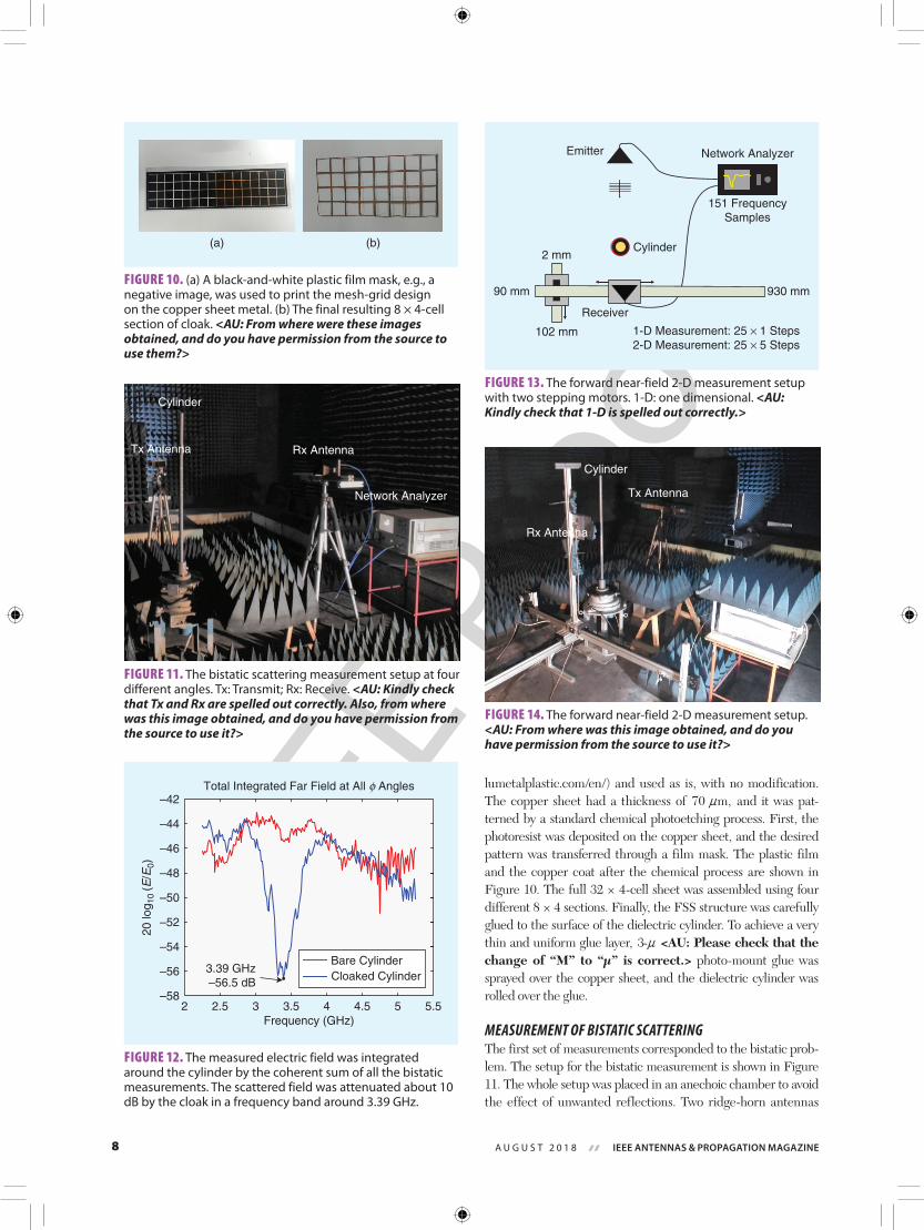
lumetalplastic.com/en/) and used as is, with no modification. The copper sheet had a thickness of ,70 mn and it was pat-terned by a standard chemical photoetching process. First, the photoresist was deposited on the copper sheet, and the desired pattern was transferred through a film mask. The plastic film and the copper coat after the chemical process are shown in Figure 10. The full 32 × 4-cell sheet was assembled using four different 8 × 4 sections. Finally, the FSS structure was carefully glued to the surface of the dielectric cylinder. To achieve a very thin and uniform glue layer, 3-n <AU: Please check that the change of “M” to “μ” is correct.> photo-mount glue was sprayed over the copper sheet, and the dielectric cylinder was rolled over the glue.
MEASUREMENT OF BISTATIC SCATTERINGThe first set of measurements corresponded to the bistatic prob-lem. The setup for the bistatic measurement is shown in Figure 11. The whole setup was placed in an anechoic chamber to avoid the effect of unwanted reflections. Two ridge-horn antennas
Cylinder
Rx AntennaTx Antenna
Network Analyzer
FIGURE 11. The bistatic scattering measurement setup at four different angles. Tx: Transmit; Rx: Receive. <AU: Kindly check that Tx and Rx are spelled out correctly. Also, from where was this image obtained, and do you have permission from the source to use it?>
–58
–56
–54
–52
–50
–48
–46
–44
–42Total Integrated Far Field at All φ Angles
Bare CylinderCloaked Cylinder
3.39 GHz–56.5 dB
20 lo
g 10
(E/E
0)
2 2.5 3 3.5 4 4.5 5 5.5Frequency (GHz)
FIGURE 12. The measured electric field was integrated around the cylinder by the coherent sum of all the bistatic measurements. The scattered field was attenuated about 10 dB by the cloak in a frequency band around 3.39 GHz.
Emitter
Receiver
Network Analyzer
Cylinder2 mm
102 mm
930 mm
151 FrequencySamples
1-D Measurement: 25 × 1 Steps2-D Measurement: 25 × 5 Steps
90 mm
FIGURE 13. The forward near-field 2-D measurement setup with two stepping motors. 1-D: one dimensional. <AU: Kindly check that 1-D is spelled out correctly.>
Rx Antenna
Tx Antenna
Cylinder
FIGURE 14. The forward near-field 2-D measurement setup. <AU: From where was this image obtained, and do you have permission from the source to use it?>
(a) (b)
FIGURE 10. (a) A black-and-white plastic film mask, e.g., a negative image, was used to print the mesh-grid design on the copper sheet metal. (b) The final resulting 8 × 4-cell section of cloak. <AU: From where were these images obtained, and do you have permission from the source to use them?>

IEEE P
roof
9IEEE ANTENNAS & PROPAGATION MAGAZINE A U G U S T 2 0 1 8
that cover the frequency range 2–15 GHz were mounted on tripods and connected to each of the ports of an automatic network analyzer. One of the antennas remained fixed, and the other was placed at 45°, 90°, 135°, and 180°. The S11 measure-ment provided the back-scattering at 0° and S12 at the remain-ing positions. Time-domain gating was applied to filter out the antenna reflection in the S11 measurements.
Figure 12 shows the coherent summation of the bistatic measurements obtained at different angular positions as a func-tion of the operating frequency. Despite the simple cloak design, the scattering attenuation achieved by this prototype was approximately 10 dB. Noticeably, the attenuation peak was located at 3.4 GHz instead of the design frequency (i.e., 3.77 GHz). The most likely expla-nation for this discrepancy is the lack of manufacturing precision, since small inaccuracies lead to variations of the surface impedance that shift the can-celation frequency of the field scattered by the cloak with that of the dielectric cylinder. Although the technique was narrow-band in nature, a remarkable bandwidth of the order of 100 MHz was achieved.
MEASUREMENT OF NEAR-FIELD MAGNITUDE A second set of measurements was car-ried out to measure the field distribu-tion behind the cylinder. The goal of the measurements was to verify that the field distributions measured around the cloaked-cylinder prototype resembled those that would be measured without the presence of the cylinder. A ridge-horn antenna was used to produce the illuminating fields on the test zone. The measuring distance was chosen to be at least ten wavelengths away from the antenna to ensure plane-wave condi-tions on the cylinder. No specific level calibration was performed since only relative measurements were of interest, e.g., comparing the fields without the cylinder, with the cylinder, and with the cloaked cylinder.
Two stepping motors were used to measure the magnitude and phase of the forward near field in a 2-D grid. As shown in Figure 13, the emitter anten-na remained static while the receiv-er was moved along five rows in the y-direction, measuring 25 field samples
in each row in the x-direction. The anechoic chamber setup can be observed in Figure 14.
Figures 15 and 16 show the measurements in the 2-D grid of Figure 13 for, respectively, the frequency of minimum scattering (i.e., 3.39 GHz) and a frequency far away from the cloaking band (i.e., 2.75 GHz). The grid was located behind the cylinder in the forward near-field zone, at a minimum distance of approximately 50 cm from the cylinder surface, as shown in Figures 13 and 14.
100
6020
100 200 300 400 500 600x (mm)
700 800 900
0.060.050.040.03
Free Space |E |, f = 3.39 GHz
100
6020
100 200 300 400 500 600x (mm)
700 800 900
0.060.050.040.03
Bare Cylinder |E |, f = 3.39 GHz
100
6020
100 200 300 400 500 600x (mm)
700 800 900
0.060.050.040.03
Cloaked Cylinder |E |, f = 3.39 GHz
FIGURE 15. The 2-D measurement of forward-field magnitude for the free-space measurement (i.e., the incident field with no cylinder) and the bare dielectric and cloaked cylinder at the frequency of minimum scattering (i.e., 3.39 GHz). As expected, the cloak partly restores the incident-field distribution for operating frequencies in the cloaking band.
100
6020
100 200 300 400 500 600x (mm)
700 800 900
0.060.050.040.03
Free Space |E |, f = 2.75 GHz
100
6020
100 200 300 400 500 600x (mm)
700 800 900
0.060.050.040.03
Bare Cylinder |E |, f = 2.75 GHz
100
6020
100 200 300 400 500 600x (mm)
700 800 900
0.060.050.040.03
Cloaked Cylinder |E |, f = 2.75 GHz
FIGURE 16. The 2-D measurement of forward-field magnitude for the free-space measurement (i.e., the incident field with no cylinder), the bare dielectric cylinder, and the cloaked one at a frequency far away from the cloaking band (2.75 GHz). At this frequency, there is no cloaking effect, and the incident field is heavily distorted by the presence of the bare or cloaked cylinder.

IEEE P
roof
10 IEEE ANTENNAS & PROPAGATION MAGAZINE A U G U S T 2 0 1 8
Results for the free-space measurement (i.e., with no cyl-inder), the bare dielectric cylinder, and the cloaked one were compared. The free-space measurement with no cylinder gave the picture of the incident field that impinged over the cylinder. The presence of the bare cylinder distorted the incident field,
producing a reflection (i.e., standing wave) in the backward direction and shadow in the forward direction. It was expected that the scattered-field attenuation due to the cloak (Figure 12) would reduce its magnitude to one much smaller than that of the incident field for operating frequencies in the cloaking band (i.e., 3.39 GHz). The total field (i.e., incident plus scattered) was, therefore, similar to the incident one: the cloaked cylinder was nearly transparent and did not perturb the incident field.
However, this cloaking effect should not be visible at other frequencies (i.e., 2.75 GHz), for which the incident field should be heavily distorted by the pres-ence of the bare or cloaked cylinder.
In the free-space measurement, we observed the 2-D field distribution of the transmitting horn antenna (i.e., the incident field). The bare dielectric cyl-inder distorted the field in both Figures 15 and 16. As expected, the cloak partly restored the incident-field distribution at 3.39 GHz (i.e., the cloaking band) in Figure 15, but not at 2.75 GHz (i.e., far away from the cloaking band) in Figure 16.
To check the performance of for-ward near-field cloaking versus operat-ing frequency, in Figure 17 we have integrated into the 2-D near-field grid the absolute value of the difference between the free space and the bare or cloaked-cylinder near-field magnitudes. Since the cloaked-cylinder near field
Frequency (GHz)
0.1
0.2
0.3
0.4
0.5
0.6
0.7
0.8
2.75 GHz
3.39 GHz
3.61 GHz
2 2.5 3 3.5 4 4.5 5 5.5
Bare CylinderCloaked Cylinder
2-D Integral of Absolute (|Ecylinder| – |Efree space|)
FIGURE 17. The absolute value of the difference between the free-space (i.e., incident) field and the cloaked-cylinder field magnitudes, integrated for all points into the 2-D near-field grid. The red and blue lines correspond to the difference between the free-space field and, respectively, the bare- or cloaked-cylinder fields. The black circles show the frequencies of 2.75 and 3.39 GHz, corresponding to the results in Figures 15 and 16, and the frequency for which the cloak best restores the incident field (i.e., 3.61 GHz), corresponding to Figure 18.
100
6020
100 200 300 400 500 600x (mm)
700 800 900
0.060.050.040.03
Free Space |E |, f = 3.61 GHz
100
6020
100 200 300 400 500 600x (mm)
700 800 900
0.060.050.040.03
Bare Cylinder |E |, f = 3.61 GHz
100
6020
100 200 300 400 500 600x (mm)
700 800 900
0.060.050.040.03
Cloaked Cylinder |E |, f = 3.61 GHz
FIGURE 18. The 2-D measurement of forward-field magnitude for the free-space measurement (i.e., the incident field with no cylinder) and the bare dielectric and cloaked cylinder at the frequency of minimum difference between the free-space and the cloaked-cylinder near field (i.e., 3.61 GHz). The cloak partly restores the incident-field distribution.
5
4.5
4
3.5
2.5
3
f (G
Hz)
100 200 300 400 500 600 700 800 900x (mm)
2
4
6
8
10
12
14
16
18
× 10–3
Field DifferenceAlong First Row of Measurement Grid
FIGURE 19. The absolute value of the difference between the free-space and the cloaked-cylinder field magnitudes along the first row (i.e., the x-direction) of the 2-D measurement grid versus the frequency. The cloaking band between 3.4 and 3.7 GHz—in which the incident and the cloaked-cylinder fields are similar so that the difference between them is small—is clearly visible as a horizontal, dark blue region.

IEEE P
roof
11IEEE ANTENNAS & PROPAGATION MAGAZINE A U G U S T 2 0 1 8
was similar to the incident one for operating frequencies in the cloaking band, we observed that the difference between them was, indeed, much smaller in the cloaking band than outside. This effect was not visible for the bare-cylinder near field.
Figure 17 shows a result similar to that of the bistatic scat-tering measurement in Figure 12, but the forward near-field cloaking band was between 3.4 and 3.7 GHz, while in Figure 12 the maximum attenuation of far-field scattering was between 3.3 and 3.4 GHz. Figure 18 shows the forward near field for the free-space and bare- and cloaked-cylinder measurements at the frequency of 3.61 GHz, for which the cloak best restored the incident field. Again, the total field distribution was heavily distorted by the presence of the bare cylinder, while the near field with cloak resembled the unperturbed incident field (i.e., the free-space measurement, without the cylinder), as expected.
It is remarkable that, according to Figure 4, in the band between 3.4 and 3.7 GHz, the surface impedance of the cylin-drical FSS was close to the value of 192.5 Ω, which theoretically canceled the scattered field at 3.77 GHz. To display the similar-ity between the free space and the cloaked-cylinder near-field magnitudes versus operating frequency, Figures 19 and 20 show two cuts of the difference between the two field magnitudes; Figure 19 shows a horizontal cut in the x-direction along the first row of the 2-D measurement grid, while Figure 20 shows a vertical cut along the forward y-direction, which is the center column of the 2-D measurement grid.
The cloaking band between 3.4 and 3.7 GHz, in which the incident and cloaked-cylinder fields were similar so that the difference between them was small, is visible as a dark blue, horizontal region in Figure 19 and a vertical region in Figure 20.
Figure 21 displays the near-field magnitude along the first row (i.e., the x-direction) of the 2-D measurement grid for the three measurements—free space (i.e., with no cylinder), bare, and cloaked cylinders—at the frequency of best incident-field restoration (i.e., 3.61 GHz). As expected, the near field was dis-torted by the presence of the bare cylinder, and the scattering cancelation due to the cloak produced a cloaked-cylinder field close to the incident one.
CONCLUSIONSA full process for the design, simulation, prototyping, and measurement of a simple and effective FSS-based mantle cloak for electrically small dielectric cylinders at 3.77 GHz has been presented. Full-wave 3-D simulations showed excellent agree-ment with theory. An original approach has been introduced to compute the effective surface impedance of the cylindrical metasurface, from either measured or simulated far fields.
Experimental prototype measurements showed about 10-dB scattered-field attenuation at a relatively broad band of 100 MHz at 3.4 GHz, although the scattering cancelation tech-nique was theoretically narrow-band. Near-field measurements in the forward direction demonstrated that the cloak partly restored the incident field in a wider band between 3.4 and 3.7 GHz.
AUTHOR INFORMATIONPedro Yuste ([email protected]) is a consultant in the tele-communications field. <AU: Please note that bios have been trimmed in accordance to magazine style. Please provide the author’s current affiliation and research interests.>
Juan M. Rius ([email protected]) is a professor at the
5
4.5
4
3.5
2.5
3
y (m
m)
2.5 3 3.5 4 4.5 5f (GHz)
2
4
6
8
10
12
14
16
18
× 10–3Field Difference Along Forward Direction
FIGURE 20. The absolute value of the difference between the free-space and the cloaked-cylinder field magnitudes along the forward y-direction (i.e., the center column of the 2-D measurement grid) versus the frequency. The cloaking band between 3.4 and 3.7 GHz—in which the incident and the cloaked-cylinder fields are similar so that the difference between them is small—is clearly visible as a vertical, dark blue region.
x (mm)
0.035
0.04
0.045
0.05
0.055
0.06
Field Magnitude AlongFirst Row of Measurement Grid, f = 3.61 GHz
Bare CylinderCloaked CylinderFree Space
0 200 400 600 800 1,000
FIGURE 21. The near-field magnitude along the first row (i.e., the x-direction) of the 2-D measurement grid, for the free-space measurement (i.e., the incident field, with no cylinder) and the bare dielectric and cloaked cylinder at the frequency of best near-field restoration (i.e., 3.61 GHz). The near field is distorted by the presence of the bare cylinder, while the scattering cancelation due to the cloak produces a cloaked-cylinder field close to the incident one.

IEEE P
roof
12 IEEE ANTENNAS & PROPAGATION MAGAZINE A U G U S T 2 0 1 8
CommSensLab, Universitat Politècnica de Catalunya–Barcelona Tech, Spain. His research interests include developing efficient algorithms for numerical analysis of electrically large antennas and scatterers, using either high-frequency approxima-tions or integral equations.
Jordi Romeu ([email protected]) is a professor at the CommSensLab, Universitat Politècnica de Catalunya–Barcel-onaTech, Spain. His research interests include antennas, electro-magnetic scattering and imaging, and system miniaturization for wireless and sensing industrial and bio applications.
Sebastián Blanch ([email protected]) is an associate pro-fessor at the CommSensLab, Universitat Politècnica de Catalun-ya–BarcelonaTech, Spain. His research interests include antenna near-field measurements, antenna diagnostics, and antenna design.
Alexander Heldring ([email protected]) is an associate professor at the CommSensLab, Universitat Politècnica de Cata-lunya–BarcelonaTech, Spain. His research interests include inte-gral equation methods for electromagnetic problems and wire antenna analysis.
Eduard Ubeda ([email protected]) is an associate profes-sor at the CommSensLab, Universitat Politècnica de Catalunya–BarcelonaTech, Spain. His research interests include numerical computation of scattering and radiation using integral equations.
REFERENCES[1] A. Alù and N. Engheta, “Achieving transparency with plasmonic and meta-material coatings,” Phys. Rev. E., vol. 72, p. 016,623, July 2005. <AU: Please check that the page number is correct.>[2] A. Alù and N. Engheta, “Multifrequency optical invisibility cloak with layered plasmonic shells,” Phys. Rev. Lett., vol. 100, Mar. 2008. <AU: Please provide page range.>[3] J. B. Pendry, D. Schurig, and D. R. Smith, “Controlling electromagnetic fields,” Sci., vol. 312, no. 5781, pp. 1780–1782, June 2006. [4] C. Caloz and T. Itoh, Electromagnetic Metamaterials: Transmission Line Theory and Microwave Applications. Hoboken, NJ: Wiley, 2005.[5] G. V. Eleftheriades and K. G. Balmain, Eds., Negative-Refraction Metamate-rials. Hoboken, NJ: Wiley, 2005.[6] D. Schurig, J. J. Mock, B. J. Justice, S. A. Cummer, J. B. Pendry, A. F. Starr, and D. R. Smith, “Metamaterial electromagnetic cloak at microwave frequen-cies,” Sci., vol. 314, no. 5801, pp. 977–980, Nov. 2006.[7] B. Edwards, A. Alù, M. G. Silveirinha, and N. Engheta, “Experimental veri-fication of plasmonic cloaking at microwave frequencies with metamaterials,” Phys. Rev. Lett., vol. 103, Oct. 2009. <AU: Please provide page range.>[8] B. I. Popa and S. A. Cummer, “Cloaking with optimized homogeneous aniso-tropic layers,” Phys. Rev. A, vol. 79, no. 2, 2009. <AU: Please provide page range.>[9] J. Andkjr and O. Sigmund, “Topology optimized low-contrast all-dielecteric optical cloak,” Appl. Phys. Lett., vol. 98, no. 2, 2011. <AU: Please provide page range.>[10] X. Wang and E. Semouchkina, “A route for efficient non-resonance cloak-ing by using multilayer dielectric coating,” Appl. Phys. Lett., vol. 102, no. 11, 2013. <AU: Please provide page range.>[11] L. S. Kalantari and M. H. Bakr, “Wideband cloaking of objects with arbi-trary shape exploiting adjoint sensitivities,” IEEE Trans. Antennas and Propag., vol. 64, no. 5, May 2016. <AU: Please provide page range.>[12] B. A. Munk, Frequency Selective Surfaces: Theory and Design. New York: Wiley, 2000.[13] A. Alù, “Mantle cloak: Invisibility induced by a surface,” Phys. Rev. B, vol. 80, no. 24, Dec. 2009. <AU: Please provide page range.>[14] P. Y. Chen and A. Alù, “Mantle cloaking using thin patterned metasurfaces,”
Phys. Rev. B, vol. 84, no. 20, Nov. 2011. <AU: Please provide page range.>[15] P. Y. Chen, J. Soric, and A. Alù, “Invisibility and cloaking based on scatter-ing cancelation,” Advanced Materials, vol. 64, no. 44, pp. 281–304, Nov. 2012.[16] P. S. Kildal, A. A. Kishk, and A. Tengs, “Reduction of forward scattering from cylindrical objects using hard surfaces,” IEEE Trans. Antennas Propag., vol. 44, no. 11, Nov. 1996. <AU: Please provide page range.>[17] P. S. Kildal, “Artificially soft and hard surfaces in electromagnetics,” IEEE Trans. Antennas Propag., vol. 38, no. 10, pp. 1537–1544, Oct. 1990.[18] M. Riel, Y. Brand, Y. Demers, and P. de Maagt, “Performance improve-ments of center-fed reflector antennas using low scattering struts,” IEEE Trans. Antennas Propag., vol. 60, no. 3, Mar. 2012. <AU: Please provide page range.>[19] J. C. Soric, P. Y. Chen, A. Kerkhoff, D. Rainwater, K. Melin, and A. Alù, “Demonstration of an ultralow profile cloak for scattering suppression of a finite-length rod in free space,” New J. Phys., vol. 15, 2013. <AU: Please pro-vide the issue number or month and the page range.>[20] P. Y. Chen, F. Monticone, and A. Alu, “Suppressing the electromagnetic scattering with an helical mantle cloak,” IEEE Antennas Wireless Propag. Lett., vol. 10, pp. 1598–1601, 2011. <AU: Please provide the issue number or month.>[21] A. Monti, J. Soric, A. Alu, F. Bilotti, A. Toscano, and L. Vegni, “Overcom-ing mutual blockage between neighboring dipole antennas using a low-profile patterned metasurface,” IEEE Antennas Wireless Propag. Lett., vol. 11, pp. 1414–1417, 2012. <AU: Please provide the issue number or month.>[22] J. C. Soric, A. Monti, A. Toscano, F. Bilotti, and A. Al, “Dual-polarized reduction of dipole antenna blockage using mantle cloaks,” in IEEE Trans. Antennas Propag., vol. 63, no. 11, pp. 4827–4834, Nov. 2015. [23] A. Monti, J. Soric, A. Alù, A. Toscano, and F. Bilotti, “Anisotropic mantle cloaks for TM and TE scattering reduction,” IEEE Trans. Antennas Propag., vol. 63, no. 4, p. 1775, Apr. 2015. <AU: Please check that the page number is correct.>[24] P. Yuste, J. M. Rius, J. Romeu, S. Blanch, A. Heldring, and E. Ubeda, “A simple and effective microwave invisibility cloak based on frequency selective surfaces,” in Proc. 11th European Conf. Antennas and Propagation (EuCAP), Paris, France, Mar. 2017. <AU: Please provide the page range.>[25] C. A. Balanis, “Appendix IV” in Advanced Engineering Electromagnetics. New York: Wiley, 1989.[26] J. Baker-Jarvis, E. J. Vanzura, and W. A. Kissick, “Improved technique for determining complex permittivity with the transmission/reflection method,” IEEE Trans. Microw. Theory Techn., vol. 38, no. 8, pp. 1096–1103, Aug. 1990.[27] Y. R. Padooru, A. B. Yakolev, P. Y. Chen, and A. Alù, “Analytical modeling of conformal mantle cloaks for cylindrical object using sub-wavelength printed and slotted arrays,” J. Appl. Phys., vol. 112, 2012. <AU: Please provide the issue number or month and the page range.>[28] S. Rao, D. Wilton, and A. Glisson, “Electromagnetic scattering by surfaces of arbitrary shape,” IEEE Trans. Antennas Propag., vol. 30, no. 3, pp. 409–418, May 1982.[29] D. Schaubert, D. Wilton, and A. Glisson, “A tetrahedral modeling method for electromagnetic scattering by arbitrarily shaped inhomogeneous dielectric bodies,” IEEE Trans. Antennas Propag., vol. 32, no. 1, pp. 77–85, Jan. 1984. [30] C. C. Lu and W. C. Chew, “A coupled surface-volume integral equation approach for the calculation of electromagnetic scattering from composite metallic and material targets,” IEEE Trans. Antennas Propag., vol. 48, no. 12, pp. 1866–1868, Dec. 2000. [31] N. Morita, N. Kumagai, and J. R. Mautz, Integral Equation Methods for Electromagnetics. Norwood, MA: Artech House, 1990.[32] R. F. Harrington, Field Computation by Moment Methods. New York: Macmillan, 1968. [33] J. M. Rius, J. Parrón, A. Heldring, J. M. Tamayo, and E. Ubeda, “Fast itera-tive solution of integral equations with method of moments and matrix decom-position algorithm singular value decomposition,” IEEE Trans. Antennas and Propag., vol. 56, no. 8, pp. 2314–2324, Aug. 2008. [34] C. A. Balanis, Advanced Engineering Electromagnetics. New York: Wiley, 1989.[35] Dassault Systemes. Computer simulation technology. [Online]. Available: http://www.cst.com/ <AU: Please provide the year or date of access if pos-sible.>

IEEE P
roof
13IEEE ANTENNAS & PROPAGATION MAGAZINE A U G U S T 2 0 1 8
An FSS is probably the most cost-effective and easiest-to-implement choice for putting scattering cancelation into practice.
The aim of this article is to didactically present the complete process.
The incident and cloaked-cylinder fields were similar so that the difference between them was small.
The magnetic field inside and outside the cylinder was obtained from the electric field (7) and (8) after applying Maxwell-Faraday curl equation.
This result gave the surface reactance of the cloaking coat attached to an electrically thin cylinder that minimized the scattered field and, thus, reduced its visibility.
The cloak is expected to work successfully at a frequency of 3.78 instead of 3.77 GHz.
The bending of the FSS in a curved surface did not significantly change the surface impedance near 3.77 GHz.
The total field distribution was heavily distorted by the presence of the bare cylinder.