airwell flow logic ii vrf air conditioning systems
DESCRIPTION
AIRWELL FLOW LOGIC II VRF AIR CONDITIONING SYSTEMSTRANSCRIPT

Mini FlowLogic& FlowLogic IIcollectionR410A VRF
20122013

2 3
Contact Us
an InternatIonaL saLes network
aIrweLL HeadqUarter1bis, avenue du 8 Mai 1945
78280 GUYANCOURT FRANCe
Commercial:[email protected]
Aftersales: +33 (0)1 39 44 65 79
Web: www.airwell.com

2 3
table of contents
page
HIstorY 4
tHe FLowLogIC II soLUtIon 6
FLowLogIC II oUtdoor UnIts overvIew 8
MInI FLowLogIC II 10
Main characteristics 10
FLowLogIC II 14
Main characteristics 14
Control technology 16
Installation 18
Technical data and combinations 21
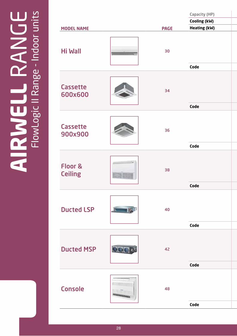
FLowLogIC II Indoor UnIts overvIew 28
High wall 30
Cassette 600x600 31
Cassette 900x900 32
Floor Ceiling 33
Console 34
Ducted Low pressure 35
Ducted Medium pressure 36
FLowLogIC II aCCessorIes 37
annexes 39
Available pipe length and height difference Mini FlowLogic II 39
Available pipe length and height difference FlowLogic II 40
Example of “print screen” from our selection software program 41

4 5
IndUstrIaL begInnIngsSince the 1950s, ACe has been mass-producing air conditioning systems for private and commercial use. At that time, the company designed the first window unit – one of its flagship products – intended for the european and African markets.
a deCade oF InnovatIonMoving forward, in 1970 Airwell split its “window” unit into two parts to form a “split” system unit, becoming the first european manufacturer to produce this product. Another string was added to its bow a few years later, in 1979, with the air-water heat pump. In the wake of the two oil crises, this system could be connected to existing fuel oil boilers in homes. And in 1982 Airwell came up with the first range of wall split systems, incorporating a remote control, a high-tech tangential flow turbine to reduce noise levels and rotary compressors.
one group, one history,many ambitions
2012 will mark the 65th anniversary of the Group’s activity and international expansion.
The Airwell Group has a long history, marked by innovations at every stage of its development. In 1947 Paul Wallet founded the company L’Air Conditionné Entreprise (ACE) near Paris and, with the brand Airwell, quickly became the leading manufacturer of direct-expansion air conditioners. The foundations had been laid for what would become one of the largest groups worldwide to offer solutions for both the residential sector and to businesses, industry and the service sector.

4 5
ongoIng expansIonAlways at the cutting edge of technology, in 1988 Airwell became the first western company to develop the Inverter system, which varies the speed of the compressor, thus enabling the temperature to be adjusted and energy savings to be made. In the 1990s, the company experienced exceptional growth, resulting in the creation of its “historic” factory in Tillières-sur-Avre, Normandy, and the acquisition of distributors in Spain, Italy, Germany and France.
an InternatIonaL dIMensIonIn 1997, Airwell joined the Israeli group, elco Holdings, which is listed on the Tel-Aviv stock exchange and is involved in many sectors: household appliances, air conditioning, retail sale of electronics and real estate. Other acquisitions, between 1998 and 2001, most notably of factories in France, Italy and China, strengthened the Group’s international position. At the same time, it expanded its distribution network to Argentina and Turkey. The first decade of the new millennium saw acquisitions in Germany (Polenz Klimatechnik) and the USA (Fedders). Finally, to strengthen its position on the Asian markets, the Airwell Group will open a new factory in Taicang (China) in June 2012.
wHat does tHe FUtUre HoLd?Many challenges lie ahead. The first is reliant on increasingly efficient, high quality products and services, which means listening to customers and ensuring a local presence. R&D is also one of the main priorities, with a desire to offer major innovations every year for each business line.

6 7
FlowLogic II, a high performance system for all those involved in the project
FlowLogic II is a range of variable refrigerant flow solutions for heating and air conditioning applications comprising of three innovative systems each utilising high performance R410A refrigerant.
This range is unmatched by anything on the market and can independently pilot up to 64 indoor units, giving a capacity of between 3 and 48HP (8 to 135 kW). The DC Inverter technology means that these systems achieve remarkable energy efficiency (COP up to 4) whilst offering ultra silent operation, and a compact footprint.
This range of products is adapted to numerous applications : residential, small businesses, major office complexes, shopping centers or hotels etc : and this is thanks to its numerous technical assets such as :
A range of single and 3 phases units,
Significant refrigerant pipe lengths and height differences,
Minimum outdoor temperature for heating mode operation -15°C,
Heating or cooling.
HIgH perForManCe sYsteM Owners or users benefit from a system which offers significant energy savings and has a direct impact on their fuel bills. The user benefits from a high performance system which guarantees optimal comfort all year round The installer benefits from the simplicity of the installation procedure The designer benefits from a number of tools (software and documents) which make it easier to calculate the dimensions of the system.

6 7
optIMaL energY savIngs –good For tHe envIronMentThe energy efficiency of the FlowLogic II range is exceptional thanks to the use of DC Inverter compressors and the use of variable speed fan motors. Therefore for 1 kW of electricity used by the system, up to 4 kW of heat output is generated. As the units operate using R410A, the entire range of products contributes to the preservation of the environment (high performance “green” fluid, recyclable and harmless to the ozone layer, reduction in energy consumption) within the framework of the Renewable energy plan.
sILent operatIonThe Twin Rotary and Scroll DC Inverter compressors are fitted across the entire FlowLogic II range producing a significant reduction in noise levels and vibrations that guarantees silent running.
a CoMpLete range oF Indoor UnIts and ControL devICesAll indoor units and control devices are the same across the two systems of the Airwell Mini FlowLogic II and FlowLogic II range.
Cassette CBV 600x600
Floor ceiling FAV
Cassette CCV 900x900
Console BAV
Ducted DBV
High wall HAV
Ducted DAV

8 9
aIr
weL
L R
An
gE
Flow
Logi
c II
Ran
ge -
Out
door
uni
ts
ModeL naMe pageCapaCItY
Hppower sUppLY
Capacity (HP) 3 6 10 14 16 20 24 26 28 30 32 34 36 38 40 42 46 48
Cooling (kw) 8.0 18.0 28.0 40.0 45.0 56.0 68.0 73.0 80.0 85.0 90.0 96.0 101.0 108.0 113.0 118.0 130.0 135.0
Code Heating (kw) 9.5 20.0 31.5 45.0 50.0 63.0 76.5 81.5 87.5 95.0 100.0 108.0 113.0 119.0 126.5 131.5 145.0 150.0
Mini FlowLogic II
10
3 1PH 230 V 7SP14H006
6 3PH 400 V 7SP14H009
FlowLogic II 14
10 3PH 400 V 7SP14H002
14 3PH 400 V 7SP14H004
16 3PH 400 V 7SP14H005

8 9
ModeL naMe pageCapaCItY
Hppower sUppLY
Capacity (HP) 3 6 10 14 16 20 24 26 28 30 32 34 36 38 40 42 46 48
Cooling (kw) 8.0 18.0 28.0 40.0 45.0 56.0 68.0 73.0 80.0 85.0 90.0 96.0 101.0 108.0 113.0 118.0 130.0 135.0
Code Heating (kw) 9.5 20.0 31.5 45.0 50.0 63.0 76.5 81.5 87.5 95.0 100.0 108.0 113.0 119.0 126.5 131.5 145.0 150.0
Mini FlowLogic II
10
3 1PH 230 V 7SP14H006 1
6 3PH 400 V 7SP14H009 1
FlowLogic II 14
10 3PH 400 V 7SP14H002 1 2 1 1 2 2 1 1 1
14 3PH 400 V 7SP14H004 1 1 2 1 1 2 1 1
16 3PH 400 V 7SP14H005 1 1 1 2 1 1 2 2 3

10
Mini FlowLogic II |
11
2-WAY MINI FLOWLOGIC IIComposed of three and single phase units of 3 & 6 HP, this range is designed for residential use or for light commercial use.
DC Inverter rotary compressor (YCV 080)
Realize high efficiency and compact designed compressor by joint wrap & rare metal magnet motor.
Wide range inverter compressors would satisfy the customer’s innovative requirement and design.
Highly efficient DC scroll compressor (YCV 180)The highly efficient scroll compressor is equipped with a “Flexible Mechanism” that allows movement in the axial direction of the frame supporting the cradle scroll. This greatly reduces both leakage and friction loss, ensuring very high efficiency throughout the speed range.
DC fan motor
DC fan motor speed can be adjusted from 0~1000 r/min, it can improve the unit efficiency, at the same time, the unit can realize low ambient cooling operation.
DC Inverter technologyDC Inverter motor. High efficiency. Low vibration, low noise. High reliability.
L'ATTEINTE DE LA TEMPÉRATUREDEMANDÉE EST RÉDUITE
DE 30% AVEC UN SYSTÈME DC INVERTER
TEMPÉRATUREINTÉRIEURE
Économies d'énergie
TEMPÉRATUREDEMANDÉE
SYSTÈMEVITESSE FIXE
SYSTÈMEDC INVERTER
DEMARRAGEDE L'UNITÉ
TEMPÉRATUREINTÉRIEURE
Consommation d'énergieélevée
PRODUCT ADVANTAGES COP can reach 4.1 Up to 9 units can be connected Single phase electrics Compact (0.32 m2 footprint)
Minimum outdoor temperature for heating mode operation -15°C Minimum outdoor temperature for cooling mode operation -5°C DC Inverter compressor and ventilator Refrigerant tubing lengths of up to 150 m

10 11
preCIse ControL
180 degree veCtor ControL teCHnoLogY
PID controlPID control adjusts the output of compressor and the open degree of eeV, balances the indoor regrigerant flow, realizes the linear output, creates a comfortable environment. The temperature could be control precisely.
FeaturesAirwell using power resistance to detect the rotor position of compressor, results in the consistency of the compressor working current and Current Sine waves, improve power efficiency about 17%.

12
Mini FlowLogic II |
13
OPERATIOn RAnGEMini FlowLogic II series permits a system design considering a heating range operation under a low temperature condition from -15°C of previous model and a cooling range operation -5°C.
For the capacities under low temperature conditions, please see technical data sheets.
COnTROL AnD SAFETyControl compressor running frequency by temp. Sensor, more precise and prompt than conventional control system.Protections: pressure, temp., compressor, fan motor, refrigerant, oil quantity etc. Realize perfect performance.Malfunction self-diagnose.DC fan motor (yCV 180).
DC Inverter compressor, high efficiency.
Single set valve, easy to installation and save installation time.
12 13
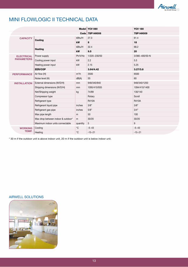
mini flowlogic ii technical data
Model YCV 080 YCV 180
Code 7SP14H006 7SP14H009
CAPACItyCooling
kBtu/H 27.3 61.4
kW 8 18
HeatingkBtu/H 32.4 68.2
kW 9.5 20
ElECtrICAl PArAmEtErs
Power supply Ph/V/Hz 1/220~230/50 3/380~400/50-n
Cooling power input kW 2.2 5.5
Heating power input kW 2.15 5.25
EER/COP 3.64/4.42 3.27/3.8
PErFormAnCE Air flow (H) m3/h 3500 6500
noise level (H) dB(A) 55 60
InstAllAtIon External dimensions (W/D/H) mm 948/340/840 948/340/1250
Shipping dimensions (W/D/H) mm 1095/410/935 1094/410/1400
net/Shipping weight kg 74/89 130/140
Compressor type Rotary Scroll
Refrigerant type R410A R410A
Refrigerant liquid pipe inches 3/8” 3/8”
Refrigerant gas pipe inches 5/8” 3/4”
Max pipe length m 50 100
Max drop between indoor & outdoor* m 30/20 30/20
Maximum indoor units connectable quantity 5 9
WorkIng tEmP.
Cooling °C -5~43 -5~43
Heating °C -15~21 -15~21
* 30 m if the outdoor unit is above indoor unit, 20 m if the outdoor unit is below indoor unit.
AIRWELL SOLUTIONS

14
FlowLogic II |
15
DC Inverter Compressor high efficiency
Use high efficiency DC Inverter scroll compressor, high efficiency, low noise.note: not only use DC Inverter compressor, some models also use fix speed compressor, pls. refer to the service manual details.
DC fan motorThe speed of the wide range DC fan motor can be adjusted from 0 to 1000 r/min.
Compared to conventional AC motors, a DC fan motor offers greater operating efficiency, especially during low-speed rotation. The efficiency could be 90%.
2-WAY FlowLogic IIComposed of DC Inverter models 10, 14 & 16 HP, this new generation of units enables a capacity range from 10 to 48 HP to be covered by combining up to 3 units. This range offers noise pressure levels that vary between 55 and 66 dB(A) without a silent mode, making these units the quietest on the market.
PRODUCT ADVANTAGES The whole range is DC Inverter. Capacity range from 10 to 48 HP. COP average of 3.9 COP can reach 4.1, which is a 15% COP increase in relation to the previous range
12% increase in EER in relation to the previous range 40 indoor units connectable from 24HP to only 2 outdoor units
Minimum outdoor temperature of heating mode operation -20°C
DC Inverter fan Noise levels: 51.5 dB(A)*
Power Ratio 130% Indoor Units Identical to the FlowLogic 3 way and Mini FlowLogic R410A ranges Control device identical to the 3 way FLOW LOGIC and Mini FlowLogic R410A ranges. Unit dimensions optimised De-icing between outdoor units Lead lag operation to maintain equal operating time Total connection length 300 metres Wide range of control systems (Wireless control devices, touch screen central controller, GTC gateway.)
efficiency

14 15
Efficient structurenew big diameter “aviation” fanThis new fan could reduce air loss, air resistance and noise, increase heat exchange efficiency.
4-way air return heat exchanger technologyThe 4-way air return.The compressor and condenser ar placed in separated compartments.This structure of outdoor unit can realize lower air resistance, higher heat efficiency and lower noise level.
Energy save lock function26°C in cooling mode, 20°C in heating mode, lock function, save operation cost
Setting temperature fixed to 26°C, the air conditioner operation cost can reduce 10%.
At the same time, the 26°C is healthy to the human body.
eFFICIent parts
advanCe ControL teCHnoLogY
sub-cooling circuitSub-cooling circuit utilizes little refrigerant to cool most of refrigerant in system, and makes it a further cooling, improves sub-cooling degree of refrigerant, in can avoid energy loss due to refrigerant flash evaporating when it goes through PMV.It will increase cooling capacity by 6%, reduce refrigerant circulation amounts, so that it can increase the efficiency of system.
180° vector drive control technologyUsing the power resistance to detect the position of rotor in compressor, so that the operation current of compressor close to sine wave easily.
Efficient exchangerW-model Ø8 inner grooved tube.Hydrophylic aluminium coil fin.It will increase efficiency of heat exchange by 5%.

16
FlowLogic II |
17
preCIse ControL
ControL teCHnoLogY
PID controlPID control adjusts the output of compressor and the open degree of eeV, balances the indoor regrigerant flow, realizes the linear output, creates a comfortable environment. The temperature could be control precisely.
Wireless remote controller (standard for wall mounted and console type). Realize standard control function.
Max 16 indoor units (all the indoor units work in the same mode). Set ON/OFF time. Mode selection: cool/heat/fan. Temperature setting. Failure code display.
Wired & Group controller (standard for cassette, convertible and duct type). Max 16 indoor units (all the indoor units work in the same mode). Realize Master & Slave control using 2 controller. Set ON/OFF time.
comfort
control
Variable control mode
simple controller (optional)
RCV01
RWV01
RWV03

16 17
bMs ControL
ControL teCHnoLogY
BVm01simple Airwell A/C management system
RS-485 communication length is max 1000m. Total connected indoor units quantity is limited 400. energy pulse meter is optional.
Central controller (optional) Touch screen. Max RS-485 communication wire length is 1000m. Max connectable indoor units groups quantity is 128. Weekly timer function included. Zones creation. Central control mode.
BVm02network Airwell A/C management system
Total actual connected indoor units quantity is max 1000. Internet remote control. Separate purchase parts by dealers/customers: - computer display; - energy pulse meter and printer if calculating
the power consumption requested. Interface: BACnet and modbus.
RWV02
ADV01
Bus64 units maxi per link system
Group n°1
Maxi23
ADV01
Group n°2
16 units maxi per group command
128 groups maxi
Group n°8
RWV02

18
FlowLogic II |
19
FLexIbLe InstaLLatIon
easY InstaLLatIon
easY transportatIon long piping length & large drop
Total refrigerant piping length. Max 300m refrigerant piping length. Max 50m height drop between indoor and outdoor units (outdoor unit above, 40m if outdoor unit below). Max 15m height drop between indoor units.
Concise systemComparing with chiller system, without filter, stop valves, accessory, FlowLogic II units refregerant piping greatly reduce the system installation work and save a lot of protection & clean work.
Wiring systemA wiring system is used to enable shared use of the wiring between indoor & outdoor units and the central control wiring, with a simple wiring operation. The only work you need to do is to connect the central controller to the outdoor unit directly if central controller is adopted.
modularized designThe outdoor units’ space only occupies 0.74m2 and 1.04m2, it can transport with elevators, save lots of transport cost and time.The outdoor units can installed in different floors, sace the whole system test time.
installation

18 19
advanCed teCHnoLogY dUtY CYCLIng
reLIabLe operatIon
High quality DC Inverter compressorThe highly efficient scroll compressor is equipped with a “frame compliance mechanism” that allows movement in the axial direction of the frame supporting the cradle scroll. This greatly reduces both leakage and friction loss, ensuring very high efficiency throughout the speed range.
Duty cycling of outdoor unitsThe outdoor units make no difference between primary unit and secondary unit. For the system which consists of more than one unit, the operating turns of units will be changed every 8 hours.Duty cycling of outdoor units could balance the operation hours and life of each outdoor unit in order to prolong the system’s life.
Backup operationIf one outdoor unit malfunction happens the other units provide emergent operation until repair achieved. In one module system, also can realize backup operation when fix speed compressor error happens. The backup operation could avoid the system close down due to one unit going wrong, it is quite reliable to use.
Auto checking malfunctionFailure codes displayed by LeD by 4x7 segments display in outdoor PCB or controllers are so detailed for us to find the fail place more quickly, and can judge the failure content easily.
High quality Inverter moduleInverter module imported from Japan, design and evaluate according to Japanese standard (7 items, 45 specifications).
more reliable outdoor PCBAll the hardware evaluated by the expert. Part design according to Japanese design standard. Improve the process, adopt the advanced method, painted with insulation paint, and tested at high ambient temperature to make sure good quality.
reliability

20
FlowLogic II |
21
reLIabLe test test in the development phase
Capability and safty test 500 hours salt spray test 6 hours rain test 130% over-match test 300m pipe lenght & 50m drop test eMC test
test during manufacturing Manufacture test Parts test / Leak test / Operation test / Safty test Outgoing test Visual test / Function test / Capacity test / Acoustic test Accessories test
Airwell products
Enthalpy difference testing lab
Climate simulating lab
Noise testing lab
Quality EMC lab
Center control
Auto-test line
Helium leak test
support
soFtware seLeCtIon prograM
This software supply a solution of piping & wiring design, can help the designer select the right material lists, basic wiring diagram and control wiring diagram etc.Airwell also offers a computer selection program for defining size, piping, wiring diagram, and list of material (this software is only a tool to assist with decision making) and the results of it is directly dependant of the input data from the customer, so these data are provided for information purpose only and should not replace a study carried out by an approval filter.

20 21
flowlogic ii technical data for 10, 14 and 16 hP
Model YCV 280 YCV 400 YCV 450
Code 7SP14H002 7SP14H004 7SP14H005
CAPACIty Cooling kW 28 40 45
Heating kW 31.5 45 50
ElECtrICAl PArAmEtErs
Power supply Ph/V/Hz 3/380~400/50-n 3/380~400/50-n 3/380~400/50-n
Power input (A)
CoolingRated/Max current 11.1/23.4 3/4”/28.5 20.3/31.6
Rated/Max power input 7.36/14.7 11.4/17.9 13.4/19.99
HeatingRated/Max current 12.5/19 17.96/24.9 19.3/27.3
Rated/Max power input 7.97/11.9 11.6/15.6 13.5/17.1
PErFormAnCE Air flow (H) m3/h 11100 14100 14100
noise level (H) dB(A) 57 60 60
InstAllAtIon External dimensions (W/D/H) mm 990/750/1808 1390/750/1808 1390/750/1808
Shipping dimensions (W/D/H) mm 1090/860/1990 1490/860/1990 1490/890/1990
net/Shipping weight kg 240/255 360/378 368/386
Compressor type Scroll Scroll Scroll
Refrigerant type R410A R410A R410A
Refrigerant charge kg 11 12 14.5
Refrigerant liquid pipe inches 3/8” 1/2” 1/2”
Refrigerant gas pipe inches 7/8” 1” 1”1/8
Oil equalization pipe inches 3/8” 3/8” 3/8”
Environment temperature range
Cooling °C -5~43 -5~43 -5~43
Heating °C -15~21 -15~21 -15~21
Maximum indoor units connectable quantity 16 16 26
AIRWELL SOLUTIONS

22
FlowLogic II |
23
technical data for 10-10 combination
Model YCV 560
Combination Model / Code YCV 280 / 7SP14H002
YCV 280 / 7SP14H002
CAPACIty Cooling kW 56
Heating kW 63
ElECtrICAl PArAmEtErs
Power supply Ph/V/Hz 3/380~400/50-n
Power input (A)
CoolingRated/Max current 22.2/46.8
Rated/Max power input 14.72/29.4
HeatingRated/Max current 25/28
Rated/Max power input 15.94/23.8
PErFormAnCE Air flow (H) m3/h 22200
noise level (H) dB(A) 60
InstAllAtIon External dimensions (W/D/H) mm 950/750/1808 + 990/750/1808
Shipping dimensions (W/D/H) mm 1090/860/1990 + 1090/860/1990
net/Shipping weight kg 480/510
Compressor type Scroll
Refrigerant type R410A
Refrigerant charge kg 22
Refrigerant liquid pipe inches 5/8”
Refrigerant gas pipe inches 1”1/8
Oil equalization pipe inches 3/8”
Environment temperature range
Cooling °C -5~43
Heating °C -15~21
Maximum indoor units connectable quantity 33
AIRWELL SOLUTIONS

22 23
technical data for 10-14 combination
Model YCV 680
Combination Model / Code YCV 280 / 7SP14H002
YCV 400 / 7SP14H004
CAPACIty Cooling kW 68
Heating kW 76.5
ElECtrICAl PArAmEtErs
Power supply Ph/V/Hz 3/380~400/50-n
Power input (A)
CoolingRated/Max current 30.15/51.9
Rated/Max power input 18.76/32.6
HeatingRated/Max current 30.46/43.9
Rated/Max power input 19.57/27.5
PErFormAnCE Air flow (H) m3/h 25200
noise level (H) dB(A) 61
InstAllAtIon External dimensions (W/D/H) mm 950/750/1808 + 1390/750/1808
Shipping dimensions (W/D/H) mm 1090/860/1990 + 1490/860/1990
net/Shipping weight kg 600/633
Compressor type Scroll
Refrigerant type R410A
Refrigerant charge kg 23
Refrigerant liquid pipe inches 5/8”
Refrigerant gas pipe inches 1”1/8
Oil equalization pipe inches 3/8”
Environment temperature range
Cooling °C -5~43
Heating °C -15~21
Maximum indoor units connectable quantity 39
AIRWELL SOLUTIONS

24
FlowLogic II |
25
technical data for 10-16, 14-14 & 14-16 combinationS
Model YCV 730 YCV 800 YCV 850
Combination Model / Code YCV 280 / 7SP14H002 YCV 400 / 7SP14H004 YCV 400 / 7SP14H004
YCV 450 / 7SP14H005 YCV 400 / 7SP14H004 YCV 450 / 7SP14H005
CAPACIty Cooling kW 73 78.5 85
Heating kW 81.5 87.5 95
ElECtrICAl PArAmEtErs
Power supply Ph/V/Hz 3/380~400/50-n 3/380~400/50-n 3/380~400/50-n
Power input (A)
CoolingRated/Max current 31.4/55 34.5/56.3 39.35/60.1
Rated/Max power input 20.76/34.69 23.4/35.49 24.8/37.89
HeatingRated/Max current 1”1/4/46.3 34.4/49 37.26/52.2
Rated/Max power input 21.47/29 23.5/30.7 25.1/32.7
PErFormAnCE Air flow (H) m3/h 25200 28200 28200
noise level (H) dB(A) 61 62 62
InstAllAtIon External dimensions (W/D/H) mm 950/750/1808 + 1390/750/1808
1390/750/1808 + 1390/750/1808
1390/750/1808 + 1390/750/1808
Shipping dimensions (W/D/H) mm 1090/860/1990 + 1490/860/1990
1490/860/1990 + 1490/860/1990
1490/860/1990 + 1490/860/1990
net/Shipping weight kg 608/641 728/756 728/764
Compressor type Scroll Scroll Scroll
Refrigerant type R410A R410A R410A
Refrigerant charge kg 25.5 26.5 26.5
Refrigerant liquid pipe inches 3/4” 3/4” 3/4”
Refrigerant gas pipe inches 1”1/4 1”1/4 1”1/4
Oil equalization pipe inches 3/8” 3/8” 3/8”
Environment temperature range
Cooling °C -5~43 -5~43 -5~43
Heating °C -15~21 -15~21 -15~21
Maximum indoor units connectable quantity 43 46 50
AIRWELL SOLUTIONS

24 25
technical data for 16-16, 10-10-14 & 10-10-16 combinationS
Model YCV 900 YCV 960 YCV 1010
Combination Model / Code YCV 450 / 7SP14H005 YCV 280 / 7SP14H002 YCV 280 / 7SP14H002
YCV 450 / 7SP14H005 YCV 280 / 7SP14H002 YCV 280 / 7SP14H002
- YCV 400 / 7SP14H004 YCV 450 / 7SP14H005
CAPACIty Cooling kW 90 96 101
Heating kW 100 108 113
ElECtrICAl PArAmEtErs
Power supply Ph/V/Hz 3/380~400/50-n 3/380~400/50-n 3/380~400/50-n
Power input (A)
CoolingRated/Max current 40.6/63.2 41.25/75.3 42.5/78.4
Rated/Max power input 26.8/39.98 26.12/47.3 28.12/49.39
HeatingRated/Max current 38.6/54.6 42.96/62.9 44.3/65.3
Rated/Max power input 27/34.2 27.54/39.4 29.4/40.9
PErFormAnCE Air flow (H) m3/h 28200 36300 36300
noise level (H) dB(A) 62 63 63
InstAllAtIonExternal dimensions (W/D/H) mm 1390/750/1808 +
1390/750/1808
950/750/1808 + 950/750/1808 + 1390/750/1808
950/750/1808 + 950/750/1808 + 1390/750/1808
Shipping dimensions (W/D/H) mm 1490/860/1990 + 1490/860/1990
1090/860/1990 + 1090/860/1990 + 1490/860/1990
1090/860/1990 + 1090/860/1990 + 1490/860/1990
net/Shipping weight kg 736/772 840/888 848/896
Compressor type Scroll Scroll Scroll
Refrigerant type R410A R410A R410A
Refrigerant charge kg 29 34 36.5
Refrigerant liquid pipe inches 3/4” 3/4” 3/4”
Refrigerant gas pipe inches 1”1/4 1”1/4 1”1/2
Oil equalization pipe inches 3/8” 3/8” 3/8”
Environment temperature range
Cooling °C -5~43 -5~43 -5~43
Heating °C -15~21 -15~21 -15~21
Maximum indoor units connectable quantity 53 56 59
AIRWELL SOLUTIONS

26
FlowLogic II |
27
technical data for 10-14-14, 10-14-16 & 10-16-16 combinationS
Model YCV 1080 YCV 1130 YCV 1180
Combination Model / Code YCV 280 / 7SP14H002 YCV 280 / 7SP14H002 YCV 280 / 7SP14H002
YCV 400 / 7SP14H004 YCV 400 / 7SP14H004 YCV 450 / 7SP14H005
YCV 400 / 7SP14H004 YCV 450 / 7SP14H005 YCV 450 / 7SP14H005
CAPACIty Cooling kW 106.5 113 118
Heating kW 119 126.5 131.5
ElECtrICAl PArAmEtErs
Power supply Ph/V/Hz 3/380~400/50-n 3/380~400/50-n 3/380~400/50-n
Power input (A)
CoolingRated/Max current 45.6/79.7 50.45/83.5 51.7/86.6
Rated/Max power input 30.76/50.19 32.16/52.69 34.16/54.68
HeatingRated/Max current 46.9/68 49.76/71.2 51.1/73.6
Rated/Max power input 31.47/42.6 33.07/44.6 34.97/46.1
PErFormAnCE Air flow (H) m3/h 39300 39300 39300
noise level (H) dB(A) 63 63 63
InstAllAtIonExternal dimensions (W/D/H) mm
950/750/1808 + 1390/750/1808 + 1390/750/1808
950/750/1808 + 1390/750/1808 + 1390/750/1808
950/750/1808 + 1390/750/1808 + 1390/750/1808
Shipping dimensions (W/D/H) mm1090/860/1990 + 1490/860/1990 + 1490/860/1990
1090/860/1990 + 1490/860/1990 + 1490/860/1990
1090/860/1990 + 1490/860/1990 + 1490/860/1990
net/Shipping weight kg 968/1011 968/1019 976/1027
Compressor type Scroll Scroll Scroll
Refrigerant type R410A R410A R410A
Refrigerant charge kg 37.5 37.5 40
Refrigerant liquid pipe inches 3/4” 3/4” 3/4”
Refrigerant gas pipe inches 1”1/2 1”1/2 1”1/2
Oil equalization pipe inches 3/8” 3/8” 3/8”
Environment temperature range
Cooling °C -5~43 -5~43 -5~43
Heating °C -15~21 -15~21 -15~21
Maximum indoor units connectable quantity 63 64 64
AIRWELL SOLUTIONS

26 27
technical data for 14-16-16 & 16-16-16 combinationS
Model YCV 1300 YCV 1350
Combination Model / Code YCV 400 / 7SP14H004 YCV 450 / 7SP14H005
YCV 450 / 7SP14H005 YCV 450 / 7SP14H005
YCV 450 / 7SP14H005 YCV 450 / 7SP14H005
CAPACIty Cooling kW 130 135
Heating kW 145 150
ElECtrICAl PArAmEtErs
Power supply Ph/V/Hz 3/380~400/50-n 3/380~400/50-n
Power input (A)
CoolingRated/Max current 59.65/91.7 60.9/94.8
Rated/Max power input 38.2/57.88 40.2/59.97
HeatingRated/Max current 56.56/79.5 57.9/81.9
Rated/Max power input 38.6/49.8 40.5/51.3
PErFormAnCE Air flow (H) m3/h 42300 42300
noise level (H) dB(A) 64 64
InstAllAtIonExternal dimensions (W/D/H) mm
1390/750/1808 + 1390/750/1808 + 1390/750/1808
1390/750/1808 + 1390/750/1808 + 1390/750/1808
Shipping dimensions (W/D/H) mm1490/860/1990 + 1490/860/1990 + 1490/860/1990
1490/860/1990 + 1490/860/1990 + 1490/860/1990
net/Shipping weight kg 1096/1150 1104/1158
Compressor type Scroll Scroll
Refrigerant type R410A R410A
Refrigerant charge kg 41 43.5
Refrigerant liquid pipe inches 3/4” 3/4”
Refrigerant gas pipe inches 1”1/2 1”1/2
Oil equalization pipe inches 3/8” 3/8”
Environment temperature range
Cooling °C -5~43 -5~43
Heating °C -15~21 -15~21
Maximum indoor units connectable quantity 64 64
AIRWELL SOLUTIONS
28 29
aIr
weL
L R
An
gE
Flow
Logi
c II
Ran
ge -
Indo
or u
nits
ModeL naMe page
Capacity (HP) 7 9 12 16 18 24 28 30 38 48
Cooling (kw) 2.2 2.8 3.6 4.5 5.6 7.1 8 9 11.2 14
Heating (kw) 2.2 2.8 3.6 4.5 5.6 7.1 8 9 11.2 14
Hi Wall 30
Code 7SP02H001 7SP02H002 7SP02H003 7SP02H005
Cassette 600x600
34
Code 7SP04H001 7SP04H002 7SP04H003
Cassette 900x900
36
Code 7SP04H005 7SP04H007 7SP04H009
Floor & Ceiling
38
Code 7SP02H008 7SP02H011
Ducted LSP 40
Code 7SP03H002
Ducted MSP 42
Code 7SP03H007 7SP03H009 7SP03H011
Console 48
Code 7SP05H002

28 29
ModeL naMe page
Capacity (HP) 7 9 12 16 18 24 28 30 38 48
Cooling (kw) 2.2 2.8 3.6 4.5 5.6 7.1 8 9 11.2 14
Heating (kw) 2.2 2.8 3.6 4.5 5.6 7.1 8 9 11.2 14
Hi Wall 30
Code 7SP02H001 7SP02H002 7SP02H003 7SP02H005
Cassette 600x600
34
Code 7SP04H001 7SP04H002 7SP04H003
Cassette 900x900
36
Code 7SP04H005 7SP04H007 7SP04H009
Floor & Ceiling
38
Code 7SP02H008 7SP02H011
Ducted LSP 40
Code 7SP03H002
Ducted MSP 42
Code 7SP03H007 7SP03H009 7SP03H011
Console 48
Code 7SP05H002

30
FlowLogic II |
31
HAV tecHnicAl dAtA
HAVHIGH WAll
EEV inside putThe EEV box inside put, easy for installation.
High-quality DC fan motorReduce the indoor unit noise greatly.
New fashion design Infrared remote controller included on standard.
AIRWELL SOLUTIONS
RCV01(STD)
Dimensions: 007-009-012 models
Dimensions: 018 model
Model HAV 007 HAV 009 HAV 012 HAV 018
Code 7SP02H001 7SP02H002 7SP02H003 7SP02H005
CAPACItyCooling
kBtu/H 7.5 9.5 12.3 19.1
kW 2.2 2.8 3.6 5.6
HeatingkBtu/H 8.5 10.9 13.6 21.5
kW 2.5 3.2 4 6.3
ElECtrICAl PArAmEtErs Power supply Ph/V/Hz 1/220~230/50 1/220~230/50 1/220~230/50 1/220~230/50
PErFormAnCE Air flow (H/M/L) m3/h 600 600 600 800
noise level (H/M/L) dB(A) 37/33/31 37/34/31 41/36/33 43/39/34
InstAllAtIon External dimensions (W/D/H) mm 938/187/265 938/187/265 938/187/265 1046/234/299
Shipping dimensions (W/D/H) mm 1016/304/360 1016/304/360 1016/304/360 1126/344/388
net/Shipping weight kg 10.9/12.6 10.9/12.6 10.9/12.6 13/16.5
Refrigerant liquid pipe inches 1/4” 1/4” 1/4” 3/8”
Refrigerant gas pipe inches 1/2” 1/2” 1/2” 5/8”
ControllerWired not available not available not available not available
Infrared RCV01 (S)* RCV01 (S)* RCV01 (S)* RCV01 (S)*
* O: optional, S: standard.

30 31
CBV teChniCal data
CBVCASSETTE 600x600
New particular design Quiet operation Built-in high head drain pump Fresh air inlet Wired controller RWV01 included on standard EEV inside
Model CBV 009 CBV 012 CBV 016
Code 7SP04H001 7SP04H002 7SP04H003
CAPACItyCooling
kBtu/H 9.5 12.3 15.3
kW 2.8 3.6 4.5
HeatingkBtu/H 10.9 13.6 17.1
kW 3.2 4 5
ElECtrICAl PArAmEtErs Power supply Ph/V/Hz 1/220~230/50 1/220~230/50 1/220~230/50
PErFormAnCE Air flow (H/M/L) m3/h 700 700 700
noise level (H/M/L) dB(A) 32/30/29 32/30/29 33/30/29
InstAllAtIon External dimensions (W/D/H) mm 570/570/260 570/570/260 570/570/260
Shipping dimensions (W/D/H) mm 718/680/380 718/680/380 718/680/380
net/Shipping weight kg 19/21 19/21 19/21
Refrigerant liquid pipe inches 1/4” 1/4” 1/4”
Refrigerant gas pipe inches 3/8” 1/2” 1/2”
PAnEl Code panel 7ACVFH001 7ACVFH001 7ACVFH001
External dimensions (W/D/H) mm 700/700/60 700/700/60 700/700/60
Shipping dimensions (W/D/H) mm 740/750/115 740/750/115 740/750/115
net/Shipping weight kg 2.8/4.8 2.8/4.8 2.8/4.8
ControllerWired RWV01 (S)* RWV01 (S)* RWV01 (S)*
Infrared RCV01 (O)* RCV01 (O)* RCV01 (O)*
* O: optional, S: standard.
AIRWELL SOLUTIONS
Dimensions: 009-012-016 models
PRODUCT ADVANTAGES The cassette external dimension is 570x570x260mm for easy installation. It is universal and harmony with standard ceiling 600x600mm. There is no breakage for ceiling during installation. Airflow pass through the outlet smoothly and fluently owing to the streamline air outlet. Bring you a much more quiet space. The fan blade adopts the design of irregular helix. The indoor unit can run at the lowest sound level. Built-in Drain Pump drains water automatically. A standard drain-head height of up to 600mm is possible, creating the ideal solution for perfect water drainage. Pre-set fresh air inlet, can introduce the outside fresh air into the room, greatly improve the indoor air quality (optional).
RCV01(optional)
RWV01 RWV03(optional)

32
FlowLogic II |
33
CCVCASSETTE 900x900
Compact design Advance structure facilitating cleanin and installation
Fresh air inlet New particular panel design EEV inside Wired controller RWV01 included on standard
Dimensions: 024-030-048 modelsPRODUCT ADVANTAGES Adopt the compact design the thick of the main body is only 290mm. So even the inner space of the ceiling is narrow the unit can also be installed easily.
The suction grille can be rotated by 90° and its installation direction can be selected randomly.
Pre-set fresh air inlet, can introduce the outside fresh air into the room, greatly improve the indoor air quality (optional).
From small to big size use the same appearance panel, harmoney with the environment and with consistance appearance.
CCV teChniCal data
AIRWELL SOLUTIONS
Model CCV 024 CCV 030 CCV 048
Code 7SP04H005 7SP04H007 7SP04H009
CAPACIty CoolingkBtu/H 24.2 30.7 47.7
kW 7.1 9 14
HeatingkBtu/H 27.3 34.1 54.6
kW 8 10 16
ElECtrICAl PArAmEtErs Power supply Ph/V/Hz 1/220~230/50 1/220~230/50 1/220~230/50
PErFormAnCE Air flow (H/M/L) m3/h 1200 1800 1800
noise level (H/M/L) dB(A) 35/34/31 37/35/31 42/39/35
InstAllAtIon External dimensions (W/D/H) mm 840/840/240 840/840/295 840/840/295
Shipping dimensions (W/D/H) mm 930/930/330 930/930/390 930/930/390
net/Shipping weight kg 30/36 38/40 38/40
Refrigerant liquid pipe inches 3/8” 3/8” 3/8”
Refrigerant gas pipe inches 5/8” 5/8” 5/8”
PAnEl Code panel 7ACVFH002 7ACVFH002 7ACVFH002
External dimensions (W/D/H) mm 950/950/80 950/950/80 950/950/80
Shipping dimensions (W/D/H) mm 985/985/115 985/985/115 985/985/115
net/Shipping weight kg 6/9 6/9 6/9
ControllerWired RWV01 (S)* RWV01 (S)* RWV01 (S)*
Infrared RCV01 (O)* RCV01 (O)* RCV01 (O)*
* O: optional, S: standard.
RCV01(optional)
RWV01 RWV03(optional)

32 33
FAVFlooR & CEIlING
Ultra-thin unit body, only thick 199mm (24 model) Wide-angle airflow Quiet running EEV inside Wired controller RWV01 included on standard
Dimensions: 012-024 modelsPRODUCT ADVANTAGES The convertible indoor unit adopts a double drain pan design. The unit body is very thin, only 199mm. It is beautiful, elegant and space saving. 100° wide angle louvers and 70° wide angle blades design to make a precise control of the airflow. It averagely distributes the comfortable iar to every corner of the room. Thanks to the low sound level centrifugal fan, the unit always works quietly so as to give more comfort to life.
AIRWELL SOLUTIONS
FAV technicAl dAtAModel FAV 012 FAV 024
Code 7SP02H008 7SP02H011
CAPACIty CoolingkBtu/H 12.3 24.2
kW 3.6 7.1
HeatingkBtu/H 13.6 27.3
kW 4 8
ElECtrICAl PArAmEtErs Power supply Ph/V/Hz 1/220~230/50 1/220~230/50
PErFormAnCE Air flow (H/M/L) m3/h 800 800
noise level (H/M/L) dB(A) 48/46/44 48/46/44
InstAllAtIon External dimensions (W/D/H) mm 990/665/199 990/665/199
Shipping dimensions (W/D/H) mm 1150/750/300 1150/750/300
net/Shipping weight kg 28.3/34.3 28.3/34.3
Refrigerant liquid pipe inches 1/4” 3/8”
Refrigerant gas pipe inches 1/2” 5/8”
ControllerWired RWV01 (S)* RWV01 (S)*
Infrared RCV01 (O)* RCV01 (O)*
* O: optional, S: standard.
RCV01(optional)
RWV01 RWV03(optional)

34
FlowLogic II |
35
EVACoNSolE
High efficiency filter Quiet running Compact unit body and space saving Fast temperature adjustment EEV inside Blowing up and down
Dimensions: 012 modelPRODUCT ADVANTAGES The unit adopt high efficiency filter, can efficiently filter the dirt etc., and improve the room air quality.
Thanks to the low sound level centrifugal fan, the unit always works quietly so as to give more comfort to life.
The unit body is very thin and harmonious with room. It is beautiful, elegant and space saving.
Air supplying from top or the bottom of the unit body for fast temperature adjustment.
EVA tEchnicAl dAtA
AIRWELL SOLUTIONS
Model EVA 012
Code 7SP05H002
CAPACIty CoolingkBtu/H 12.3kW 3.6
HeatingkBtu/H 13.6kW 4
ElECtrICAl PArAmEtErs Power supply Ph/V/Hz 1/220~230/50
PErFormAnCE Air flow (H/M/L) m3/h 520noise level (H/M/L) dB(A) 43/39/36
InstAllAtIon External dimensions (W/D/H) mm 762/253/640Shipping dimensions (W/D/H) mm 784/305/719net/Shipping weight kg 18/20Refrigerant liquid pipe inches 1/4”Refrigerant gas pipe inches 1/2”
ControllerWired /Infrared RCV01 (S)*
* O: optional, S: standard.
RCV01

34 35
DAVDUCTED loW STATIC PRESSURE
220 ultra thin design and space saving Elegant outlook fit with your style optional air return design optional static pressure High efficiency filter G3 EEV inside Wired controller RWV01 included on standard
Dimensions: 009 modelPRODUCT ADVANTAGES Ultra thick design make all the models have only 220mm height. It is more convenient for installation and maintenance. The indoor unit placed in the ceiling only the inlet and outlet grill can be seen. The most suited grill can be used to fit with the indoor decoration. Ther are two air return design for the different requestment. Let the decoration more optional. Two choice of optional static pressure 0 Pa and 20 Pa for the low static pressure duct make user more convenient. The unit adopts G3 grade filter which can efficiency filter the dirt etc., and improve the room air quality. At the same time, the filter can be pulled out from downside, convenient for maintenance and cleaning.
AIRWELL SOLUTIONS
RCV01(optional)
RWV01 (infrared receiver to combined with RCV 01)
DAV technicAl DAtAModel AD092MLERA
Code 7SP03H002
CAPACIty CoolingkBtu/H 9.5
kW 2.8
HeatingkBtu/H 10.9
kW 3.2
ElECtrICAl PArAmEtErs Power supply Ph/V/Hz 1/220~230/50
PErFormAnCE Air flow (H/M/L) m3/h 400
noise level (H/M/L) dB(A) 35/32/30
InstAllAtIon External dimensions (W/D/H) mm 610/484/220
Shipping dimensions (W/D/H) mm 710/545/280
net/Shipping weight kg 15/17
Refrigerant liquid pipe inches 1/4”
Refrigerant gas pipe inches 3/8”
Static pressure Pa 20
ControllerWired RWV01 (S)*
Infrared RCV01 (O)*
* O: optional, S: standard.
RWV03(optional)

36
FlowLogic II |
37
DBVDUCTED MEDIUM STATIC PRESSURE
Flexible static pressure selection, meet the customers’ personal requets
High efficiency filter G3 Special up-drainage water pump EEV inside Wired controller RWV01 included on standard Plenum for air outlet provided:- 3 Ø200 sizes 018 and 028 - 4 Ø200 size 038
Dimensions: 018-028 models
Dimensions: 038 model
PRODUCT ADVANTAGES The unit has standard static pressure (0-50 Pa) & middle static pressure (50-96 Pa) two choices, flexible air supply mode, make the installation more free and meet different personal requests.
The unit adopts G3 grade filter which can efficiently filter the dirt etc., and improve the room air quality. At the same time, the filter can be pulled out from downside, convenient for maintenance and cleaning.
The unit has a water pump whose the max. drainage height can be up to 600mm.
DBV technical Data
AIRWELL SOLUTIONS
Model DBV 018 DBV 028 DBV 038Code 7SP03H007 7SP03H009 7SP03H011
CAPACIty CoolingkBtu/H 19.1 27.3 38.2
kW 5.6 8 11.2
HeatingkBtu/H 21.5 30.7 42.6
kW 6.3 9 12.5
ElECtrICAl PArAmEtErs Power supply Ph/V/Hz 1/220~230/50 1/220~230/50 1/220~230/50
PErFormAnCE Air flow (H/M/L) m3/h 1200 1200 1900
noise level (H/M/L) dB(A) 43/37/35 43/37/35 43/37/35
InstAllAtIon External dimensions (W/D/H) mm 990/650/300 990/650/300 1410/645/350
Shipping dimensions (W/D/H) mm 1167/860/345 1167/860/345 1557/800/370
net/Shipping weight kg 39/45 39/45 59/66
Refrigerant liquid pipe inches 1/4” 3/8” 3/8”
Refrigerant gas pipe inches 1/2” 5/8” 5/8”
Static pressure Pa 50 50 50
ControllerWired RWV01 (S)* RWV01 (S)* RWV01 (S)*
Infrared RCV01 (O)* RCV01 (O)* RCV01 (O)*
* O: optional, S: standard.
RCV01(optional)
RWV01
DBV 018-028
DBV 038
(infrared receiver to combined with RCV 01)
RWV03(optional)

36 37
notes

38 39
aIr
weL
L R
An
gE
Flow
Logi
c II
Ran
ge -
Acc
esso
ries naMe Code ModeL FUnCtIon For wHat UnIts? optIonaL / CoMMents
Infrared controller 7ACElH001 RCV01 Unit operatingWall mounted
Console
Standard with high wall and consoleOptional with cassette, convertible and
ducted
Infrared controller receiver
7ACElH009 REC01 Realize infrared control for duct type Duct
Wired standard controller
7ACElH002 RWV01 Unit operating and group control (max. 16 indoor units)
Duct4-way cassette
Floor ceiling
Standard with 4-ways cassette, ducted and floor ceiling
Simplified controller 7ACElH008 RWV03 Unit operating and group control (max. 16 indoor units)
All (except for wall mounted & console type)
Central controller “Touch screen”
7ACElH003 RWV02ON/OFF function & malfunction code display (max. 128 groups)
Zone, timer, central control modeFlowLogic II Mandatory with ADV01
Connecting board 7ACElH004 ADV01 Connecting RWV02 and outdoor units FlowLogic II Mandatory with RWV02
Gather pipe 7ACFHH005 TAS20 Refrigerant gathering FlowLogic II For 2 outdoor units
Gather pipe 7ACFHH006 TAS30 Refrigerant gathering FlowLogic II For 3 outdoor units
Manifild pipe 7ACFHH001 TAU335 Refrigerant distributionTotal indoor units capacity
less than 33.5 kW
Manifild pipe 7ACFHH002 TAU506 Refrigerant distributionTotal indoor units capacity
less than 50.6 kW, but equal or bigger than 33.5 kW
Manifild pipe 7ACFHH003 TAU730 Refrigerant distributionTotal indoor units capacity
less than 73 kW, but equal or bigger than 50.6 kW
Manifild pipe 7ACFHH004 TAU1350 Refrigerant distributionTotal indoor units capacity
bigger than 73 kW
Inverter protocol adaptater
7ACElH007 ADV02 Protocol adapter and data storeage FlowLogic II Mandatory with BVM01 and BVM02
RS485&232 converter + software
7ACElH005 BMV01 BMS control(air conditioner edition)
FlowLogic II
IPC (Industrial personal computer) + software
7ACElH006 BMV02 BMS control(BACnet protocol edition)
FlowLogic II

38 39
naMe Code ModeL FUnCtIon For wHat UnIts? optIonaL / CoMMents
Infrared controller 7ACElH001 RCV01 Unit operatingWall mounted
Console
Standard with high wall and consoleOptional with cassette, convertible and
ducted
Infrared controller receiver
7ACElH009 REC01 Realize infrared control for duct type Duct
Wired standard controller
7ACElH002 RWV01 Unit operating and group control (max. 16 indoor units)
Duct4-way cassette
Floor ceiling
Standard with 4-ways cassette, ducted and floor ceiling
Simplified controller 7ACElH008 RWV03 Unit operating and group control (max. 16 indoor units)
All (except for wall mounted & console type)
Central controller “Touch screen”
7ACElH003 RWV02ON/OFF function & malfunction code display (max. 128 groups)
Zone, timer, central control modeFlowLogic II Mandatory with ADV01
Connecting board 7ACElH004 ADV01 Connecting RWV02 and outdoor units FlowLogic II Mandatory with RWV02
Gather pipe 7ACFHH005 TAS20 Refrigerant gathering FlowLogic II For 2 outdoor units
Gather pipe 7ACFHH006 TAS30 Refrigerant gathering FlowLogic II For 3 outdoor units
Manifild pipe 7ACFHH001 TAU335 Refrigerant distributionTotal indoor units capacity
less than 33.5 kW
Manifild pipe 7ACFHH002 TAU506 Refrigerant distributionTotal indoor units capacity
less than 50.6 kW, but equal or bigger than 33.5 kW
Manifild pipe 7ACFHH003 TAU730 Refrigerant distributionTotal indoor units capacity
less than 73 kW, but equal or bigger than 50.6 kW
Manifild pipe 7ACFHH004 TAU1350 Refrigerant distributionTotal indoor units capacity
bigger than 73 kW
Inverter protocol adaptater
7ACElH007 ADV02 Protocol adapter and data storeage FlowLogic II Mandatory with BVM01 and BVM02
RS485&232 converter + software
7ACElH005 BMV01 BMS control(air conditioner edition)
FlowLogic II
IPC (Industrial personal computer) + software
7ACElH006 BMV02 BMS control(BACnet protocol edition)
FlowLogic II

40 41
avaILabLe pIpe LengtH and HeIgHt dIFFerenCe MInI FLowLogIC II
annexes
YCV 080
Allowable value Piping part
lEngtH
Total length of piping (actual lenght) 50 m L1+L2+a+b+c
Longest piping L Actual length 35 m L1+L2+c
Max. pipe length from 1st branch pipe to indoor 15 m L2+c
DroPDrop between indoor and outdoor unit H
Outdoor is upper 30 m -
Outdoor is lower 20 m -
Drop between indoor units h 10 m -
YCV 180
Allowable value Piping part
lEngtH
Total length of piping (actual lenght) 100 m L1+L2+L3+L4+a+b+c+d+e
Longest piping L Actual length 70 m L1+L2+L3+L4+e
Max. pipe length from 1st branch pipe to indoor 30 m L2+L3+L4+e
DroPDrop between indoor and outdoor unit H
Outdoor is upper 30 m -
Outdoor is lower 20 m -
Drop between indoor units h 10 m -

40 41
avaILabLe pIpe LengtH and HeIgHt dIFFerenCe FLowLogIC II
Max. length Pipe in above figure
Single way total pipe length 300 m L1+L2+L3+L4+L5+L6+L7+L8+L9+L10+L11+L12+L13+L14+L15
Single way max. pipe length 150 m L1+L3+L5+L7+L13+L14
Max. pipe length from 1st branch pipe 40 m L7+L13+L14
Main pipe actual length 90 m L5
Height difference between indoor units 15 m -
Height difference between outdoor units 5 m -

42 43
exaMpLe oF “prInt sCreen” FroM oUr seLeCtIon soFtware prograMDefinition of the rooms
Indoor unit selection

42 43
Outdoor unit selection

44 45
Refrigerant diagram piping
Cable wiring diagram

44 45
notes

46 47
notes

46 47
Airwell France SAS1 bis avenue du 8 mai 194578280 GuyancourtFranceTel. +33 (0)1 39 44 78 00Fax +33 (0)1 39 44 00 [email protected]
FLO
WLO
GIC
II G
B 0
612
- S
pec
ifica
tions
sub
ject
to
chan
ge w
ithou
t no
tice.
Pic
ture
s no
n co
ntra
ctua
l. P
rinte
d in
UE
.