air conditioning systems -...
TRANSCRIPT
AIR CONDITIONING SYSTEMS
CM07WD4-B
Air conditioning is an ideal way of
controlling the temperature, movement
and cleanliness of air inside any
building, large or small. With today's
buildings being so well insulated and
increasingly full of electronic equipment,
the need for effective climate control is
greater than ever. Not only does it cool
in the summer months, but air conditioning
can also heat, doing away with the
need for separate heating systems
altogether. More and more people today
are enjoying the benefits of comfortable
working and living environments made
possible with air conditioning.
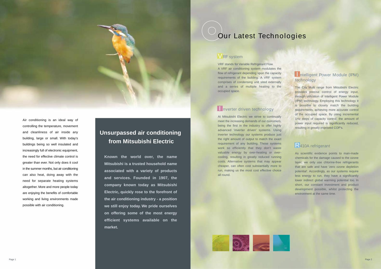
VRF system
VRF stands for Variable Refrigerant Flow.
A VRF air conditioning system modulates the
flow of refrigerant depending upon the capacity
requirements of the building. A VRF system
comprises of condensing unit sited externally
and a series of multiple heating to the
occupied space.
I nverter driven technology
At Mitsubishi Electric we strive to continually
meet the increasing demands of our customers,
being the first in the industry to offer highly
advanced ‘inverter driven’ systems. Using
inverter technology our systems produce just
the right amount of output to match the exact
requirement of any building. These systems
work so efficiently that they don’t waste
valuable energy by over-heating or over-
cooling, resulting in greatly reduced running
costs. Alternative systems that may appear
cheaper, can often cost substantially more to
run, making us the most cost effective choice
all round.
I ntelligent Power Module (IPM) technology
The City Multi range from Mitsubishi Electric
provides precise control of energy input,
through utilization of Intelligent Power Module
(IPM) technology. Employing this technology it
is possible to closely match the building
requirements, achieving more accurate control
of the occupied space. By using incremental
1Hz steps of capacity control, the amount of
power input required is significantly reduced,
resulting in greatly improved COP’s.
R410A refrigerant
As scientific evidence points to man-made
chemicals for the damage caused to the ozone
layer, we only use chlorine-free refrigerants
that are safe and have ‘zero ozone depletion
potential’. Accordingly, as our systems require
less energy to run, they have a significantly
lower indirect global warming potential too. In
short, our constant investment and product
development possible, whilst protecting the
environment at the same time.
Known the world over, the name
Mitsubishi is a trusted household name
associated with a variety of products
and services. Founded in 1907, the
company known today as Mitsubishi
Electric, quickly rose to the forefront of
the air conditioning industry - a position
we still enjoy today. We pride ourselves
on offering some of the most energy
efficient systems available on the
market.
Page 1 Page 2
Our Latest Technologies
Unsurpassed air conditioning
from Mitsubishi Electric

Sophisticated yet simple technology
VRF system
Our answer to VRF
Designed and manufactured to the highest standards, the
City Multi range offers one of the most reliable air
conditioning systems available. Simple to install and easy to
maintain, this range provides ideal solutions you can trust to
protect your investment.
Reliable
>All the City Multi outdoor units are made in Japan under stringent control.
Page 3 Page 4
Mitsubishi Electric sets the boundaries of VRF technology with the City Multi range, which is available using
R410A refrigerant with zero ODP (Ozone Depletion Potential). The range has been specifically designed for
today’s building requirements and addresses key market issues such as energy efficiency, adaptability and
reliability. With user friendly control systems utilizing Internet technology and integrated cooling and ventilation
indoor units, City Multi is the benchmark and market leader in VRF technology.
VRF is a multi and direct expansion type air conditioning system that one outdoor unit can be connected with
multiples of indoor units. The amount of refrigerant can be changed freely according to the load in the indoor unit
because inverter compressor is used in the outdoor unit. Zoning in a small office is possible with a small capacity
indoor unit. Energy conservation is easily handled because individual indoor unit can stop and start its operation
as needed. Indoor unit has a lot of models in order to suit various interior design needs. Appliance to control
separating heat of cooling in evaporation from heat in condensation is becoming important in air conditioning in the
building.
Outdoor unitJoint
Header
Inverter driven compressor
PEFY-VMS
PEFY-VMR
ON 27˚c
ON 25˚c
ON 25˚c
OFF
OFF
ON 23˚c
ON 26˚c
Controller
Indoor unit
PFFY-VKM

Unbeatable Efficiency
I nverter Driven Compressor Technology - now up to 50HP
Using inverter driven technologysaves energy for several reasons:
The unique Heat Interchange Circuit (HIC) enhances efficiency by providing additional sub-cooling and allows the
expansion device to control more effectively the refrigerant distribution, thereby increasing the operating efficiency
and reducing the volume of refrigerant in each system.
Heat Interchange Circuit
The compressor varies its speed to match the indoor cooling or heating demand and therefore only consumes the
energy that is required.
When an inverter driven system is operating at partial load, the energy
efficiency of the system is significantly higher than that of a
standard fixed speed, non inverter system.
The fixed speed system can only operate at 100%, and
partial load conditions prevail for the majority of the time.
Therefore fixed speed systems cannot match the annual
efficiencies of inverter driven systems.
Using proven single inverter driven compressor
technology, the City Multi range is favoured by the
industry for low starting currents (only 15 amps for a
16HP YHM-A outdoor unit), a smooth transition across
the range of compressor frequencies and for
eliminating systems.
100%
15%
15Hz Cooling:97HzHeating:102Hz
Heating / Cooling Capacity
Linear CapacityControl
Compressor Frequency
* image
LowStartingCurrents
LowStartingCurrents
City Multi Refrigerant CircuitCondenser
High temperature
Supercooled heat exchanger
Low temperature
Electric expansion valve
Medium temperature
Bypass
Electric expansionvalve
Hea
t exc
hang
er
Compressor
Accumulator
Evaporator
Common Refrigerant CircuitCondenser
Expansionvalve
Compressor
Accumulator
Evaporator
Page 5 Page 6
>All the City Multi compressors are inverter-driven type (4~50HP).

Total Energy Conservation
Comparison of COP (energy efficiency) – 8HP system
The difference between YHM-A and previous Mitsubishi Electric modelsTechnology is key when increased efficiency is demanded. The City Multi YHM-A range is able to deliver this in simple ways.
The importance of COP
The YHM-A range from Mitsubishi Electric provides precise control of energy input, through utilization of Intelligent
Power Module (IPM) technology. Employing this technology it is possible to closely match the building
requirements, achieving more accurate control of the occupied space. By using incremental 1Hz steps of capacity
control, the amount of power input required is significantly reduced, resulting in greatly improved COP’s.
In addition, IPM technology ensures effective performance under partial load conditions, a condition that most
systems will be in for the majority of the normal working life cycle. By taking account the efficiency at both part
load, and peak load conditions, R410A City Multi is designed to provide unbeatable year round/seasonal efficiency.
A highly efficient R410A scroll compressor design results in less friction losses at the motor. A simplified refrigerant
circuit (low pressure loss) including new accumulator design also adds a few more points to the efficiency scale.
Enhancements to the heat interchange circuit, an inverter driven fan motor and a heat exchanger design again add
vital increases to overall system efficiency and COP’s.
COP stands for “Co-efficient of performance”. It is a measure of the useful energy a system can deliver compared
to the energy it consumes. It is calculated by dividing the energy output by the energy input of a system. The
higher the figure then the more efficient the system is deemed to be, with commensurate reduced running costs.
Mitsubishi Electric VRF models, the world's highest energy-efficient ACs, will undoubtedly reduce millions of tons
of CO2 emissions.
Page 7 Page 8
I ntelligent Power Module (IPM) Technology
4.02
0R22
2.0
2.5
3.0
3.5
4.0
4.5
5.0
Our equivalent product 10 years before PUHY-200YMF
* Average COP of cooling / heating
29%Energy Saving
COP
2.87
4.33
34%EnergySaving
High COP (Coefficient of Performance) is realized
Standard model High COP model

For the Environment
History of refrigerantR22, an HCFC-based refrigerant, has been a popular choice for most chillers. R22 has been targeted by the
Montreal Protocol to be phased out in new equipment. Additionally, the European Union and other countries
governments are enforcing a ban of HCFC-based refrigerants for new installations.
Because of these restrictions, R410A refrigerants is increasingly available. R410A is a blend of HFCs, which do not
deplete the ozone but may contribute to global warming.
Technical aspects of refrigerantR410A is a more efficient refrigerant as it has a higher specific heat capacity when compared to R407C or R22.
This higher energy carrying capacity allows for smaller pipe sizes, longer pipe runs and reduces the volume of
refrigerant within a system. This is a major factor when complying with ISO5149, an International Organization for
Standardization concerning, "safety of persons and property for the design, construction, installation and operation
of refrigerating systems".
Enhancing environmental care(measures for the RoHS Directive and the refrigerant reduction)
Every unit is in compliance with the RoHS Directive,* which stands for the restriction of hazardous substances:
Lead-free soldering is used to avoid Lead Groundwater Contamination on the print board. The amount of
refrigerant on the unit has also been reduced to enhance environmental care.
* RoHS Directive: the restriction of the use of certain hazardous substances in electrical and electronic equipment that has been sold in EU since July 2006
Page 9 Page 10
Efficient R410A refrigerant
Reduction of operation noise
Improvement of COP
Improvement of COP
Improvement of reliability and easy maintenance
Page 11 Page 12
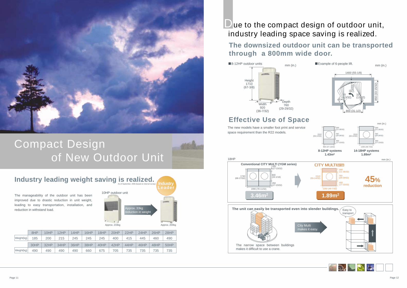
The manageability of the outdoor unit has been
improved due to drastic reduction in unit weight,
leading to easy transportation, installation, and
reduction in withstand load.
Industry leading weight saving is realized.
10HP outdoor unit
As of September, 2006 (based on internal survey)
Approx. 233kg Approx. 200kg
Approx. 33kg reduction in weight
8HP 10HP 12HP 14HP 16HP 18HP 20HP 22HP 24HP 26HP 28HP
Weight(kg) 185 200 215 245 245 245 400 415 445 460 490
30HP 32HP 34HP 36HP 38HP 40HP 42HP 44HP 46HP 48HP 50HP
Weight(kg) 490 490 490 490 660 675 705 735 735 735 735
Compact Design of New Outdoor Unit
IndustryLeaderIndustryLeader
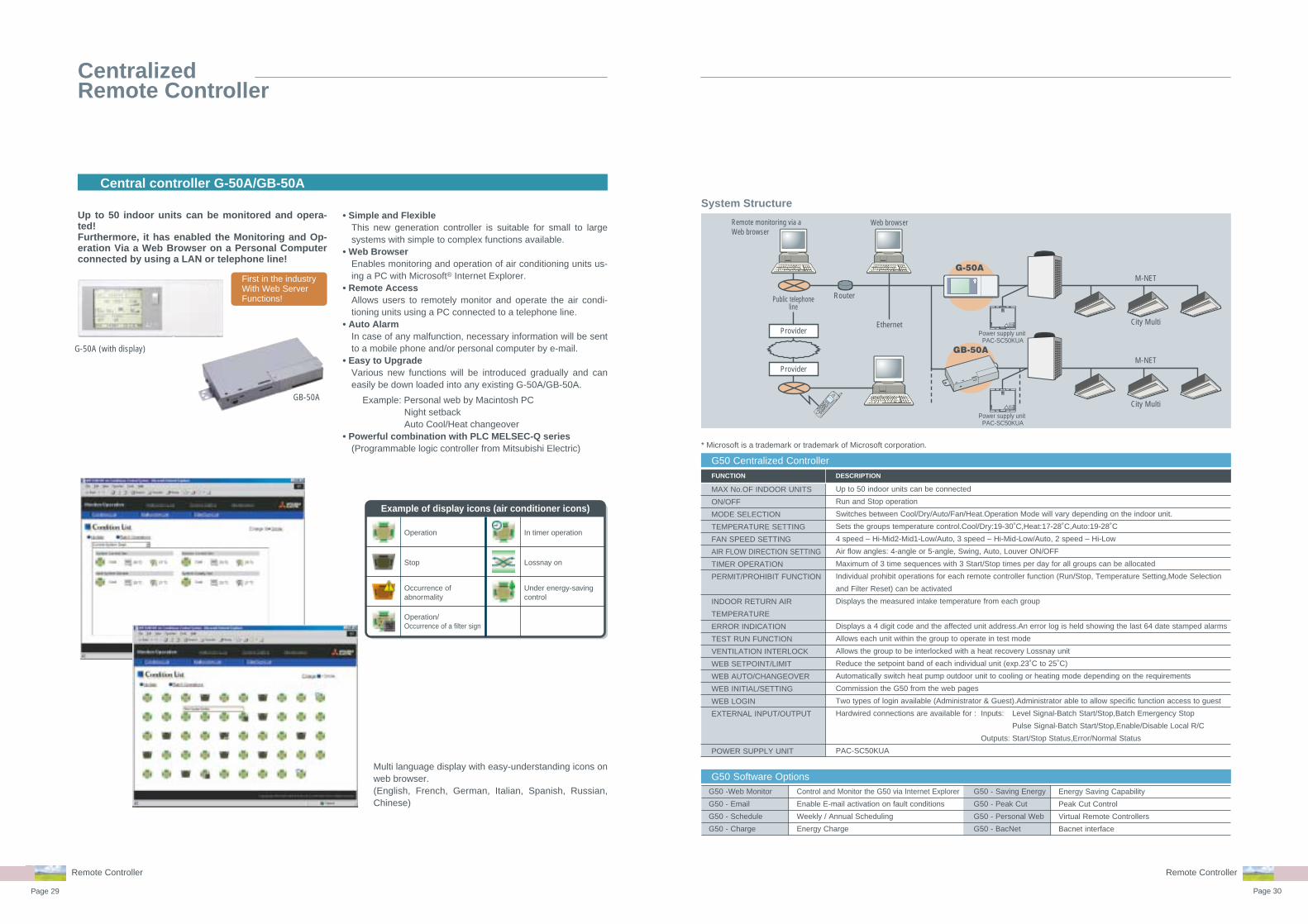
Due to the compact design of outdoor unit, industry leading space saving is realized.
The downsized outdoor unit can be transported through a 800mm wide door.
8-12HP outdoor units
Easy to transport
City Multi makes it easy.
The narrow space between buildings makes it difficult to use a crane.
800 (31-1/2)
1400 (55-1/8)
850
(33-
15/3
2)
The unit can easily be transported even into slender buildings.
Depth760
(29-29/32)
mm (in.) mm (in.)
Height1650
(64-31/32)
Height1710
(67-3/8)
Width920
(36-7/32)
10(13/32)10(13/32)
10(13/32)10(13/32)
60
11 (14/
32")
11 (14/
32)
Example of 6-people lift.
The new models have a smaller foot print and service
space requirement than the R22 models.
Conventional CITY MULTI (YGM series)
8-12HP systems1.43m2
14-18HP systems1.89m2
45%reduction
Effective Use of Space
18HP
1.89m2 3.46m2
760(29-29/32)
300(11-26/32)
450(17-23/32)
950 (37-13/32)
1510(59-14/32)
1740(68-17/32)
760(29-29/32)
300(11-26/32)
450(17-23/32)
1250 (49-7/32)
1510(59-14/32)
760(29-29/32)
300(11-26/32)
450(17-23/32)
1250 (49-7/32)
1510(59-14/32)
1990 (78-11/32)
840(33-1/16)
450(17-23/32)
450(17-23/32)
mm (in.)
mm (in.)

The Strength of City Multi
F eatures and Benefits
Increased Pipe Lengths
New Fan DesignLow Noise Levels
City Multi VRF systems led the introduction of larger single fan rotors some ten years ago, achieving substantially
lower noise levels over multiple designs. Continuing the development in the areas of blade shape and weight,
Mitsubishi Electric have managed to achieve even higher performance and lower noise levels. To reduce noise
levels further and comply with inner city residential noise regulations, all outdoor units include Night Set-back
mode. This function works by lowering the fan speed and compressor frequency proportionally with reduction in
demand.
Total system pipe lengths of up to 1000m(3280ft) and
furthest pipe lengths of 165m(541ft) make the City
Multi Y series system one of the most flexible VRF
systems in the market
New inverter driven outdoor fan motor
The compressor compartment is sealed by metal panels to attain a low noise level in all directions.
Highly efficient R410A Scroll compressor
Furthest piping length 190m[623ft] (equivalent length) (actual length 165m[541ft])
between indoor units top-bottom differential15m[49ft]
Outdoor unit
Indoor unit
Top-bottom differential 50m[164ft]
Y Series
Page 13 Page 14
NewImprovedFigures
NewImprovedFigures
LowNoise LowNoise
Low NoiseLow Noise
Newly designed refrigerant circuit (low pressure loss)

The Strength of New City Multi
R410A Pipe Sizing
Operating range in cooling is from an outdoor
temperature of -5˚C[23˚F], while that in heating has
expanded to an outdoor temperature of -20˚C[-4˚F]
Heating Operation RangeAt low ambient temperature the guaranteed operating range is now expanded to –20˚C[–4˚F] in heating and
43˚C[109˚F] in cooling.
Blue Fin Treatment
Easy Maintenance
The anti-corrosion Blue Fin treatment of the heat exchanger is especially
effective in urban environments where the traffic pollutions can damage the
aluminum fins reducing the capacity and life expectancy of the unit. All City
Multi R410A outdoor units have been treated with Blue Fin.
Automatic System CheckEnsuring simple and easy maintenance, automatic system tests are possible for wiring,
sensors and refrigerant amount.
As R410A has a higher specific heat capacity than R22, the pipework is smaller. This means the pipe itself is cheaper, easier to install and therefore less riser space is required within the building.
Conventional
Gaspiping
f28.58(f1-1/8)
Liquidpiping
f12.7(f1/2)
mm(in.)
Gaspiping
f22.2(f7/8)
Liquidpiping
f9.52(f3/8)
-20˚C[-4˚F] -10˚C[14˚F] 0˚C[32˚F] 10˚C[50˚F] 20˚C[68˚F] 30˚C[86˚F] 40˚C[104˚F]
In cooling mode
Outdoor temperature(dry bulb temperature)
Outdoor temperature(wet bulb temperature)-20˚C
[-4˚F]15.5˚C[60˚F]
In heating mode
-5˚C[23˚F]
43˚C[109˚F]
Page 15 Page 16
Based on 10HP model
Cooling Operation Set Temperature of 14˚C[57˚F]Gyms, laboratories etc often require the ability to cool lower than the standard comfort cooling setpoint. By selecting a dip switch on the unit, a cooling operation set temperature of 14˚C[57˚F] DB is possible on PFFY-VLEM/VLRM and PEFY series. The indoor unit fan will be fixed at high speed during this operation. (except PUMY)
* CITY MULTI is an air conditioning system designed for rooms and areas where people work or relax, not for machine rooms.
Even when one of the indoor units in the system is under maintenance, the other indoor unit can be operated.
* Not applicable to all situations.* Be sure to turn off the power to the indoor unit when repairing or servicing the unit.
Under maintenance In operation

Page 17 Page 18
Remote Controller
Remote Controller
Individual Remote Controller
Centralized Remote Controller
The need for control is paramount in or-der to optimise the performance of any air conditioning system and minimize its running costs. Mitsubishi Electric of-fers a wide range of control options de-signed to meet such needs.
Operating an air conditioning system without
the right control can prove costly. It's therefore
important to ensure that every system is cor-
rectly specified to the degree of control it re-
quires. Mitsubishi Electric have a wide range of
controls available 'off-the-shelf' and individual
control systems can be specifically designed to
match.
Good controls will benefit any application,
large or small. Air conditioning products need
to react to a variety of factors: different room si-
zes, usage and staff levels; changes in the cli-
mate; electronic equipment and lighting ...the
list goes on. So whatever the application, opti-
mum control of air conditioning systems is es-
sential and will result in a constant, comfort-
able environment, which in turn is both energy
and cost efficient.
A degree of differenceWhen an air conditioning system is not proper-
ly controlled, it will not run as efficiently as it
should. For every degree that the system devi-
ates from the required temperature, energy
costs can rise by up to 5%. Specify one of the
many control options from Mitsubishi Electric
to ensure air conditioning works as intended,
whilst giving the optimum amount of control.
The simpler, the betterWith the array of comprehensive control sys-
tems available from Mitsubishi Electric, it be-
comes simple to design and install air condi-
tioning systems. From a simple hand-held
controller to a G50 system - you are in control.
The importance of control

Page 19 Page 20
: Each group / Batched : Each group : Block (City Multi indoor unit only) : Batched handling (for maintenance)
: Batched only : Not available : Not used : G-50A license registration possible. ✕ –
*3: Interlock setting from local remote controller. *4: From schedule setting *5: When PAC-YT32PTA is connected.*2: Installation possible at Initial setting tool.*1: For group operation, cross-over wring is required between indoor unit.
Integrated Communications Control with Mitsubishi's Unique Transmission Network (M-NET)
Local remote controller System controller
Remote controllerSimpleremote
controller
Wirelessremote
controller
Systemremote
controllerCentralized controller
ON/OFFremote
controller
Start / Stop
Operation mode
Temperature setting
Permit / Prohibit direction
Fan speed
Air flow direction
ON/OFF
Error flashing
Error content
Filter sign
Operating hour
Operation mode
Set temperature
Indoor temperature (intake)
Permit / Prohibit
Fan speed
Air flow direction
Weekly
Annual (Designated day setting)
One day
Times of stops / Starts per day
Times of stops / Starts per week
Auto off timer
Minimum setting unit (minutes)
Error history
Daily / Monthly reports
Electricity charges
Set temperature range limit
Auto lock
Ventilation (group / interlocked)
Group setting
Block setting
Revision of electricity charges
Start / Stop
Fan speed
Ventilation mode
Status
Fan speed
Ventilation mode
Ope
ratio
nM
onito
ring
Sch
edul
ing
Rec
ordi
ngO
ther
sC
ontr
ol a
ndm
anag
emen
t
Vent
ilatio
n(g
roup
/ in
terlo
cked
)Ve
ntila
tion
(gro
up /
inte
rlock
ed)
Ope
ratio
nM
onito
ring
PAR-21MAA
1G/16units 1G/16units 1G/16units 1G/16units 16/5050/50 2000G/2000unitsGB-50A browser
50G/50units
PAR-F27MEA PAC-SE/YT51CRA(B) PAR-FL32MAPAR-FA32MA PAC-YT40ANRAPAC-SF44SRA GB-50A
G-50A browser
50G/50units
G-50A TG-2000A
Model
No. of units controllable(Groups (G) / units)
12
84
✕
✕
/
/
/
/
/ ✕
/ ✕
/
1
✕
✕
✕
✕
✕
/
/
/
/ ✕
/ ✕
✕
/
/
12
84
1
✕
✕
✕
3/3
21/21
✕
✕
✕
✕
✕
/
/
/
/ ✕
/ ✕
✕
✕
/
10
✕
✕
✕
✕
✕
✕
✕
✕
✕
✕
✕
✕
✕
✕
✕
✕
✕
✕
✕
✕
✕
✕
✕
✕ ✕
✕
✕
✕
✕
✕
1/1
✕
✕
✕
✕
✕
✕
✕ /
✕ /
✕ /
✕
10
✕
✕
✕
✕
✕
✕
✕
✕
1/1
✕
✕
✕
✕
✕
✕
✕
✕
✕
10
✕
✕
✕
8
56
1
✕
✕
✕
✕
✕
✕ /1*
*2
Scheduletimer
50G/50U
PAC-YT34STA
✕
✕
✕
✕
✕
✕
✕
✕
✕
✕
✕
16
112
5
✕
✕
✕
✕
✕
✕
✕
✕
✕
✕
✕
✕
✕
/
*4
*4
*4
*2
*2
*2
✕
✕
✕
✕
✕
/
/
/
/ ✕
/ ✕
✕✕
✕
✕
✕
✕
✕
✕
✕
✕
✕
✕
✕
✕
✕
✕
✕
✕
✕
✕
✕
✕
✕
✕
✕
✕
✕
✕
✕
✕
✕
/
/
12
84
1
*2
*2
*2
*2
/
//
✕/
✕
✕
✕
✕
✕
✕
✕
✕
✕
✕
✕
✕
✕
✕
✕
✕
✕
✕
✕
✕
✕
✕
✕
✕
✕
✕
✕
✕
✕
✕
✕
*3
✕
✕
✕
/
/
/ ✕
/
/
/ ✕
✕
✕
✕
✕
✕
✕
✕
✕
✕
✕
✕
✕
✕
✕
✕
✕
✕
✕
✕
*5
Groupremote
controller
8G/16units
PAC-SC30GRA
✕ /48
/ ✕
✕ /
/
/
/
/ ✕
/ ✕
✕
✕
✕
✕
✕
✕
✕
✕
✕
✕
*5
*5
✕ /30
✕
*5*5
*5
*5
✕ /336*5
Remote ControllerRemote Controller
System Controller
MELANSMALANS has a large line-up, including local remote controllers, timers, grouping controllers, central controllers, and centralized integrated software, PLC and its software, as well as BMS interface hardware and software etc. The combination of the MELANS products can fulfill the requirements of small-scaled control system, middle-scaled control system up to 2000 indoor units, and/or large-scaled opening system affiliated to a BMS system. Moreover, with central controller G-50A/GB-50A, PC browser and long distance remote control (monitoring and operating) via net-work is possible and easy.
C entralized Remote ControllerI ndividual Remote Controller
LMAP02 BACnetTM interface softwarePAC-YG31CDA
Interface
MITSUBISHI ELECTRIC's CITYMULTI can be easily connected to the building management system through BACnetTM.
LON WORKSTM transmission line
BACnetTM transmission line
EthernetIntegrated centralized control software TG-2000A
M-N
ET
MITSUBISHI ELECTRIC's Air-conditioner Network System (MELANS) leads air conditioner management a PC
browser and Network era.
System Remote Controller
ScheduleTimer
All of the local remote controllers feature liquid crystal and LED displays and easy to operate.
RemoteController
SimpleRemoteController
WirelessRemote Controller
PAR-F27MEA
PAR-FA32MAPAC-SE51CRAPAC-YT51CRB
PAR-FL32MA
PAR-21MAA
OUTDOOR UNITY :PUHY
INDOOR UNITPLFY-VBMPLFY-VLMDPMFY-VBMPEFY-VMRPEFY-VMSPDFY-VMPEFY-VML
PEFY-VMHPCFY-VGMPKFY-VBM / VGM / VFM PFFY-VLEMPFFY-VLRMFresh Air Intake type
A ir-Conditioning Control System
This is a specialized air condi-tioning management system, in which up to 2000 indoor units can be centrally controlled.
ON/OFFRemote Controller
PAC-YT40ANRAPAC-SF44SRA PAC-YT34STA
G-50A GB-50A
GroupRemote Controller
PAC-SC30GRA

Page 21 Page 22
Remote ControllerRemote Controller
Control SystemsIndividual Control Systems
MA remote controller
Non-polarized2-wire
Non-polarized2-wire
MA remote controller
Example of system configuration
M-NET
Wired MA remote controller PAR-21MAA
New display-Larger,easier-to-see characters• Dot matrix liquid crystal screen displays complete operating status.
• Digital display lets you set temperature in 1˚C/˚F increments.• Weekly Timer: up to 8 ON/OFF/Temperature Settings can be
made per day. The time can be set in 1-minute increments. The setting is kept in nonvolatile memory. No need to worry
about re-setting at power failure.• Equipped with a thermostat sensor in the remote controller
that makes possible more comfortable room temperature con-trol.
• Ability to limit the set temperature (upper and lower tempera-ture can be set.)
• Ability to restrict setting changes (either all changes or all ex-cept ON/OFF)
• Constantly monitors for malfunctions in the system, and is equipped with a “self-diagnosis function” that lets you know by error code immediately when a malfunction occurs.
• Dimensions: 120(W) x100(H) x 19(D) mm
Various control systems can be offered with indoor unit remote controller.
Lossnay
Remotecontroller
Remotecontroller
Outdoor unit
Cooling/Heating mode switch control
Remotecontroller
Remotecontroller
Remotecontroller
Remotecontroller
Remotecontroller
Remotecontroller
Cooling/Heating mode of the outdoor unit can be switched with the remote controller for indoor unit.
Two-remote-controllercontrolBy connecting with two re-mote controllers, an outdoor unit can be controlled freely either from the one in the room or from the one in the control room. (Last setting override) Group control is possible by using two remote controllers.
Remote controlRemote controller wiring can be extended up to 200m, which makes it possible for the indoor unit remote controllers to be instal-led at one place without being separated.
Interlocking controlHeat recovery ventilator (Lossnay) can be operated and controlled with indoor unit remote controller.
Group controlA remote controller can control up to 16 indoor units at the same time.(Automatic address setting)
Dot liquid crystal display
● Display example [Operation mode]
● Display example [Cool mode]
ON/OFF TEMP.
˚F
˚F
TIME SUN
WEEKLYSIMPLE
AUTO OFF
[Japanese]
[Russian][English]
[Itarian]
[German]
[Chinese]
[Spanish]
[French]
Various information is displayed and conveyed clearly, enabling more accurate operation of the air conditioner.
Dot Liquid Crystal Display (LCD)The dot liquid crystal display enables quick under-standing of the operation state.
Multi-language DisplayIn addition to English, contents can be displayed in sev-en other languages.This function makes the remote controller very useful in fa-cilities where foreigners are present.
Multi Language Display Example[Dot display table]
Waiting for start-up
Operation mode Cool
Dry
Heat
Auto
Auto(Cool)
Auto(Heat)
Fan
Ventilation
Stand by(Hot adjust)Defrost
Not use button
Check (Error)
Test run
Self check
Unit function selection
Setting of ventilation
Selecting language English Germany Spanish Russian Italy Chinese French Japanese

Page 23 Page 24
PAR-FL32MA
PAC-SE51CRA
PAR-FA32MA
Simple remote controller PAC-YT51CRB(MA)
Wireless remote controller PAR-FL32MA / PAR-FA32MA
Remote ControllerRemote Controller
Wired ME remote controller PAR-F27MEA
Example of system configuration
Example of system configuration
Example of system configuration
• This remote control requires non-polar wiring to only one indoor unit.
• Group operation over multiple outdoor units is possible. Grouping can be changed without re-wiring, which makes dividing rooms for tenant easier.
• Timer operation*Daily timer operation of one ON/OFF setting everyday *Auto-off timer : 0:30, 1:00, 1:30, 2:00...4:00*The setting is kept in nonvolatile memory.
• Function lockAll functions or all functions except ON / OFF can be selected.
• Set temperature range limit• Interlock setting and operation of LOSSNAY• Dimensions:130(W) x 120(H) x 19(D) mm
• No need to configure addresses for group operation.• Lit LED keeps you informed of operation - blinking even
gives you the error code via the number of blinks.• Can be used with the MA remote controller.
*When used in group configurations, wiring between indoor units is required.
*Combining ME remote controller and/or LOSSNAY remote-controller in a group is not possible.
• LCD temperature setting and display in 1˚C /1˚F unit.• Dimensions:58(W) x 159(H) x 19(D) mm
• Control: START/STOP, room temperature, fan speed, and operation mode
• The only wiring required is cross-over wiring based on two-wire signal lines.
• Room temperature sensors are built-in.• LCD temperature setting and display in 1˚C /1˚F unit.• Set temperature range limit• Can operate all types of indoor units
*Since this controller has limited functions, it should always be used in conjunction with standard controller or centralized controller.
• Dimensions:70(W) x 120(H) x 41(D) mm
Note) PAC-SE51CRA, easy group changing type, is available. Refer to the specification sheet for details.
Control SystemsIndividual Control Systems
ME R/C ME R/C
UP
Central controller
Power supply unit
SimpleMA R/C
SimpleMA R/C
Signal receiving unit
Signal receiving unit
Non-polarized2-wire
Non-polarized2-wire
Non-polarized2-wire
Wireless remote controller
Wireless remote controller
Signal receiving unit
Wireless remote controller

Page 25 Page 26
CentralizedRemote Controller
System exampleSystem example
Systemremote
controller
R / C : Remote Comtroller R / C : Remote Comtroller
PZ-52SFPZ-52SF
LOSSNAY
Power supplyunit
LOSSNAYLOSSNAY
PAR-21MAA PAR-21MAA
UP
Systemremote
controller
Schedule timer
Power supplyunit
Simple PAC-SE51CRA
PAR-F27MEA
PAR-21MAA
LOSSNAY
UP
System remote controller PAC-SF44SRA Schedule timer PAC-YT34STA
Remote ControllerRemote Controller
FUNCTION
UNITS
ON/OFF
MODE SELECTION
TEMPERATURE SETTING
FAN SPEED SETTINGS
AIR FLOW DIRECTION SETTING
PERMIT/PROHIBIT FUNCTION
ERROR INDICATION
VENTILATION INTERLOCK
EXTERNAL INPUTEXTERNAL OUTPUT
DESCRIPTION PAC-SF44SRA
50 units/50 groupMax No.Units
Run and stop operationSwitches between Cool/Dry/Auto/Fan/Heat.Operation Mode will vary depending on the indoor unit. Auto mode is available with only R2 and WR2 systemsSets the groups temperature control.Cool/Dry:19-30˚CHeat:17-28˚CAuto:19-28˚C4 speed – Hi-Mid2-Mid1-Low, Auto3 speed – Hi-Mid-Low, Auto2 speed – Hi-LowAir flow angles: 4-angle or 5-angle, Swing, Auto, Louver ON/OFFRun/Stop,Temperature Setting,Mode Selection and Filter Reset functions can be prohibited. Displays a 4 digit code and the affected unit addressAllows the group to be interlocked with a heat recovery Lossnay unitOn/Off/Fire AlarmOn/Off/Faults
• The group setting is kept in nonvolatile memory. No need to worry about re-setting at power fail-ure.
• No individual AC power supply is needed. The power can be supplied from one outdoor unit
(R410A) or Power supply unit.
• The schedule group setting is kept in nonvolatile memory. No need to worry about re-setting at power failure.
• No individual AC power supply is needed. The power can be supplied from one outdoor unit
(R410A) or Power supply unit.
One system controller can control up to fifty indoor units from one location. The PAC-SF44SRA also has hardwired connection available (On/Off input, fire alarm input, run output, fault output).
Mitsubishi Electric controllers are complimented by a weekly programmable timer, being able to control up to fifty indoor units. The PAC-YT34STA also has hardwired connection available (On/Off input, fire alarm input, run output, fault output).
System Controller
FUNCTION
UNITS
ON/OFF
SCHEDULEFUNCTION
CURRENT TIME
ERROR INDICATION
EXTERNAL INPUTEXTERNAL OUTPUT
DESCRIPTION PAC-YT34STA
50 units/50 groupMax No.Units
Run and stop operationOn/OffMode:Cool/Heat/Auto Set temperature:19˚C to 28˚COperation Prohibit: On/Off, Mode, Set temperatureWeekly timer for each group9 setting patterns + no setting16 operations per day5 minutesSet the timeDisplays a 4 digit code and the affected unit addressOn/Off/Fire AlarmOn/Off/Faults
Programmable Timer
DisplaysOperation Operation Displays
• Dimensions:130(W) x 120(H) x 19(D) mm
• Dimensions:130(W) x 120(H) x 19(D) mm
Content
Number
Unit

System example
Page 27 Page 28
ON/OFFremote
controller
LOSSNAY
PZ-52SF
PAC-YT51CRB
PAR-F27MEA
PAR-21MAA
ON/OFF remote controller PAC-YT40ANRA Group remote controller PAC-SC30GRA
Remote ControllerRemote Controller
CentralizedRemote Controller
System example
Connect to the centralized transmission line
R/C:Remote Controller
UP
Power supply unit
Group remotecontroller
PAR-21MAA PAR-21MAA
Connect to the indoor/outdoor transmission line
Group remotecontroller
PAR-21MAA PAR-21MAAR/C:Remote Controller
FUNCTION
UNITS
ON/OFF
ERROR INDICATION
VENTILATION OPERATION(INDEPENDENT)
VENTILATION OPERATION(INTERLOCKED)
EXTERNAL INPUTEXTERNAL OUTPUT
DESCRIPTION
Max No.Units
Run and stop operationLED flashes during failure.(The error code can be confirmed by removing the cover.)Group operation of only LOSSNAY units possible.*Only ON/OFF of group.The LOSSNAY will run in interlock with the operation of indoor unit.*The fan rate and mode cannot be changed. The LED will turn ON only during operation after interlocking.On/Off/Fire AlarmOn/Off/Faults
Just press a switch to start. All of the units can be On/Off by pressing the main switch, and each unit in the group can be On/Off with individual switch. The PAC-YT40ANRA also has hardwired connection available (On/Off input, fire alarm input, run output, fault output).
• The group setting is kept in nonvolatile mem-ory. No need to worry about re-setting at pow-er failure.
• No individual AC power supply is needed. The power can be supplied from one outdoor
unit (R410A) or Power supply unit.
• The group setting is kept in nonvolatile mem-ory. No need to worry about re-setting at pow-er failure.
• No individual AC power supply is needed. The power can be supplied from one outdoor
unit (R410A) or Power supply unit.
Up to 8 groups can be operated (maximum of 16 units). Just by pressing PAC-SC30GRA switches, groups can be On/Off as a batch.Suitable for small office and residential project.
• Dimensions:130(W) x 120(H) x 19(D) mm
• Dimensions:130(W) x 120(H) x 19(D) mm
FUNCTION
UNITS
ON/OFF
MODESELECTION
TEMPERATURE SETTING
FAN SPEED SETTINGS
AIR FLOW DIRECTION SETTING
PERMIT/PROHIBIT FUNCTION
INDOOR RETURN AIR TEMPERATURE
ERROR INDICATION
VENTILATION INTERLOCK
DESCRIPTION
Max No.Units
Run and stop operationSwitches betweenCool/Dry/Auto/Fan/Heat.Operation Mode will vary depending on theindoor unit. Auto mode is available with only R2 and WR2 systemsSets the groups temperature control.Cool/Dry:19-30˚CHeat:17-28˚CAuto:19-28˚C4 speed – Hi-Mid2-Mid1-Low, Auto3 speed – Hi-Mid-Low, Auto2 speed – Hi-LowAir flow angles: 4-angle or 5-angle, Swing, Auto, Louver ON/OFFRun/Stop,Temperature Setting,Mode Selectionand Filter Reset functions can be prohibitedvia main system controllerMeasures the intake temperature of themaster unit within the groupDisplays a 4 digit code and the affectedunit addressAllows the group to be interlocked with a heatrecovery Lossnay unit
PAC-SC30GRA
OPERATIONS
16 units/ 8 groupDISPLAY
PAC-YT40ANRA
OPERATIONS
50 units/16 groupDISPLAY
Page 29 Page 30
Remote ControllerRemote Controller
System Structure
Public telephoneline
G-50A
Router
Ethernet City Multi
M-NET
Remote monitoring via aWeb browser
Web browser
GB-50A
City Multi
M-NET
Provider
Provider
Operation
Example of display icons (air conditioner icons)
Stop
Occurrence of abnormality
Operation/Occurrence of a filter sign
In timer operation
Lossnay on
Under energy-saving control
Up to 50 indoor units can be monitored and opera-ted! Furthermore, it has enabled the Monitoring and Op-eration Via a Web Browser on a Personal Computer connected by using a LAN or telephone line!
First in the industryWith Web Server Functions!
* Microsoft is a trademark or trademark of Microsoft corporation.
• Simple and FlexibleThis new generation controller is suitable for small to large systems with simple to complex functions available.
• Web BrowserEnables monitoring and operation of air conditioning units us-ing a PC with Microsoft® Internet Explorer.
• Remote AccessAllows users to remotely monitor and operate the air condi-tioning units using a PC connected to a telephone line.
• Auto AlarmIn case of any malfunction, necessary information will be sent to a mobile phone and/or personal computer by e-mail.
• Easy to UpgradeVarious new functions will be introduced gradually and can easily be down loaded into any existing G-50A/GB-50A.
Example: Personal web by Macintosh PCNight setbackAuto Cool/Heat changeover
• Powerful combination with PLC MELSEC-Q series(Programmable logic controller from Mitsubishi Electric)
Multi language display with easy-understanding icons on web browser.(English, French, German, Italian, Spanish, Russian, Chinese)
G-50A (with display)
GB-50A
Central controller G-50A/GB-50A
FUNCTION
G50 Centralized Controller
G50 Software OptionsG50 - Saving Energy
G50 - Peak Cut
G50 - Personal Web
G50 - BacNet
Energy Saving Capability
Peak Cut Control
Virtual Remote Controllers
Bacnet interface
DESCRIPTION
Up to 50 indoor units can be connected
Run and Stop operation
Switches between Cool/Dry/Auto/Fan/Heat.Operation Mode will vary depending on the indoor unit.
Sets the groups temperature control.Cool/Dry:19-30˚C,Heat:17-28˚C,Auto:19-28˚C
4 speed – Hi-Mid2-Mid1-Low/Auto, 3 speed – Hi-Mid-Low/Auto, 2 speed – Hi-Low
Air flow angles: 4-angle or 5-angle, Swing, Auto, Louver ON/OFF
Maximum of 3 time sequences with 3 Start/Stop times per day for all groups can be allocated
Individual prohibit operations for each remote controller function (Run/Stop, Temperature Setting,Mode Selection
and Filter Reset) can be activated
Displays the measured intake temperature from each group
Displays a 4 digit code and the affected unit address.An error log is held showing the last 64 date stamped alarms
Allows each unit within the group to operate in test mode
Allows the group to be interlocked with a heat recovery Lossnay unit
Reduce the setpoint band of each individual unit (exp.23˚C to 25˚C)
Automatically switch heat pump outdoor unit to cooling or heating mode depending on the requirements
Commission the G50 from the web pages
Two types of login available (Administrator & Guest).Administrator able to allow specific function access to guest
Hardwired connections are available for : Inputs: Level Signal-Batch Start/Stop,Batch Emergency Stop
Pulse Signal-Batch Start/Stop,Enable/Disable Local R/C
Outputs: Start/Stop Status,Error/Normal Status
PAC-SC50KUA
G50 -Web Monitor
G50 - Email
G50 - Schedule
G50 - Charge
Control and Monitor the G50 via Internet Explorer
Enable E-mail activation on fault conditions
Weekly / Annual Scheduling
Energy Charge
MAX No.OF INDOOR UNITS
ON/OFF
MODE SELECTION
TEMPERATURE SETTING
FAN SPEED SETTING
AIR FLOW DIRECTION SETTING
TIMER OPERATION
PERMIT/PROHIBIT FUNCTION
INDOOR RETURN AIR
TEMPERATURE
ERROR INDICATION
TEST RUN FUNCTION
VENTILATION INTERLOCK
WEB SETPOINT/LIMIT
WEB AUTO/CHANGEOVER
WEB INITIAL/SETTING
WEB LOGIN
EXTERNAL INPUT/OUTPUT
POWER SUPPLY UNIT
CentralizedRemote Controller
Power supply unit PAC-SC50KUA
UP
POWER RATING
MODEL
WEIGHT
SERIAL No.
2.11kg
POWER SUPPLY UNIT
MITSUBISHI ELECTRIC CORPORATION
PAC-SC50KUA
Power supply unit PAC-SC50KUA
UP
POWER RATING
MODEL
WEIGHT
SERIAL No.
2.11kg
POWER SUPPLY UNIT
MITSUBISHI ELECTRIC CORPORATION
PAC-SC50KUA

Page 31 Page 32
Integrated centralized control software TG-2000A
1
2
3
4
5
6
7
8
Charge license
Web monitorlicense
Schedulelicense
Input G-50A
M-NET
Example of Basic System Configuration. Main features of TG-2000A
Power supply unit PAC-SC50KUA
RS-232CRS-485
Indoor unit watt-hour meter
Outdoor unit watt-hour meter
Uninterruptive power supply (UPS)
Integrated centralized controlsoftware installation
TG-2000A
Indoor unit watt-hour meter
power sourceIndoor unit watt-hour meter
Outdoor unit watt-hour meter
PLC (with electric amount count software)
Uninterruptible power supply (UPS)
Integrated centralized controlsoftware installation
TG-2000A
Indoor unit watt-hour meter
Converter
Compatible with TG-2000A Ver. 4.10 and higher * The electric amount count software or separately procured parts must be used with the designated PLC.
The TG-2000A enables the following functions using the G-50A/GB-50A option (license).
* Operation/monitor* Annual/weekly schedule* Calculating electricity* Energy saving *1* Peak cut *1*1: Compatible with TG-2000A Ver. 4.10 and higher,
G-50A Ver. 2.51 or later.
UP
POWER RATING
MODEL
WEIGHT
SERIAL No.
2.11kg
POWER SUPPLY UNIT
MITSUBISHI ELECTRIC CORPORATION
PAC-SC50KUA
Remote ControllerRemote Controller
CentralizedRemote Controller
Up to 2000 indoor units (40 G-50A/GB-50A units) can be operated and monitored simultaneously.The air-conditioner layout can be displayed on the screen, making control and operation easier.The annual and weekly schedules can be set. Two schedules, such as the summer master and winter master, can be saved in the weekly schedule.Multiple air-conditioning charges can be calculated. The power apportionment percentage data and apportioned power rate can be calculated for each indoor unit using the power apportionment function, and can be output as a CSV format file. * Power apportionment charging is not possible with the old model, A control or K control.
Charging without WHM : The user manually inputs the power rate to calculate the air-conditioning charges. (Using a tool)
RS-485 WHM charging : The RS-485 WHM value is automatically tabulated to calculate theair-conditioning charges.
PLC + pulse WHM charging : The pulse output WHM value is automatically tabulated by the PLC to calculate the air-conditioning charges.
Energy saving operation is possible using the "ON/OFF", "set temperature change", "fan operation changeover" and "performance save operation (60% to 90%)" functions.Energy saving operation matching the amount of power in use is possible by using the PLC's electric amount count software.Night set-back operation is possible with schedule settings. *1*4General equipment can be operated and monitored. *2General equipment can be schedule-controlled when using PAC-YG21CDA with PLC.For details of PLC refer to Installation Manual of PAC-YG21CDA. *3
*1: Compatible with TG-2000A Ver. 4.10 and higher, G-50A Ver. 2.51 and higher.*2: Compatible with TG-2000A Ver. 4.30 and higher, G-50A Ver. 2.51 and higher.*3: Compatible with TG-2000A Ver. 4.60 and higher, G-50A Ver. 2.70 and higher.*4: With Night Set-Back function,the CITY MULTI system can run at heating mode with target temperature set
to 12˚C/54˚Funder schedule control. This function can protect the room from dropping down to extremelylow temperature at mid-night.
Page 33 Page 34
LMAPLMAP M-NETLMAP 02
LMAP
CITY MULTI
LMAP
Example of System ConfigurationSystem design made simple through integration ofvarious devices into a total control configuration.
Outdoor unit
M-NET LON WORKS
(78kbps)
Remotecontroller
Indoor units
Remotecontroller
Indoor units
Remotecontroller
Indoor units
Remotecontroller
Indoor units
Remotecontroller
Lighting
SecurityCenter
control device
CITY MULTI System
Outdoor unit
Indoor units
Max. 50 indoor units
LON WORKS
The building management system is connected to the CITY MULTI air conditioning system using LON WORKS , which is widely used on
field networks, allowing for an open network and savings in construction to face.
LON WORKSProtocol converterbetween LON WORKS
and M-NET
LONWORKS (LMAP02) BACnet TM interface(PAC-YG31CDA)
Example of Basic System Configuration.
LAN
G-50A
Centralmonitor
BMS
TG-2000A(Optional)
Web Browser(Optional)
BACnet interface softwarePAC-YG31CDA
G-50A
M-NET
M-NET
PAC-SC50KUAPower supply unit
WHMWHM
TM
TMBACnet
UP
LON, LON WORKS and the Echelon logo are trademarks of Echelon Corporation registered in the United States and other countries.
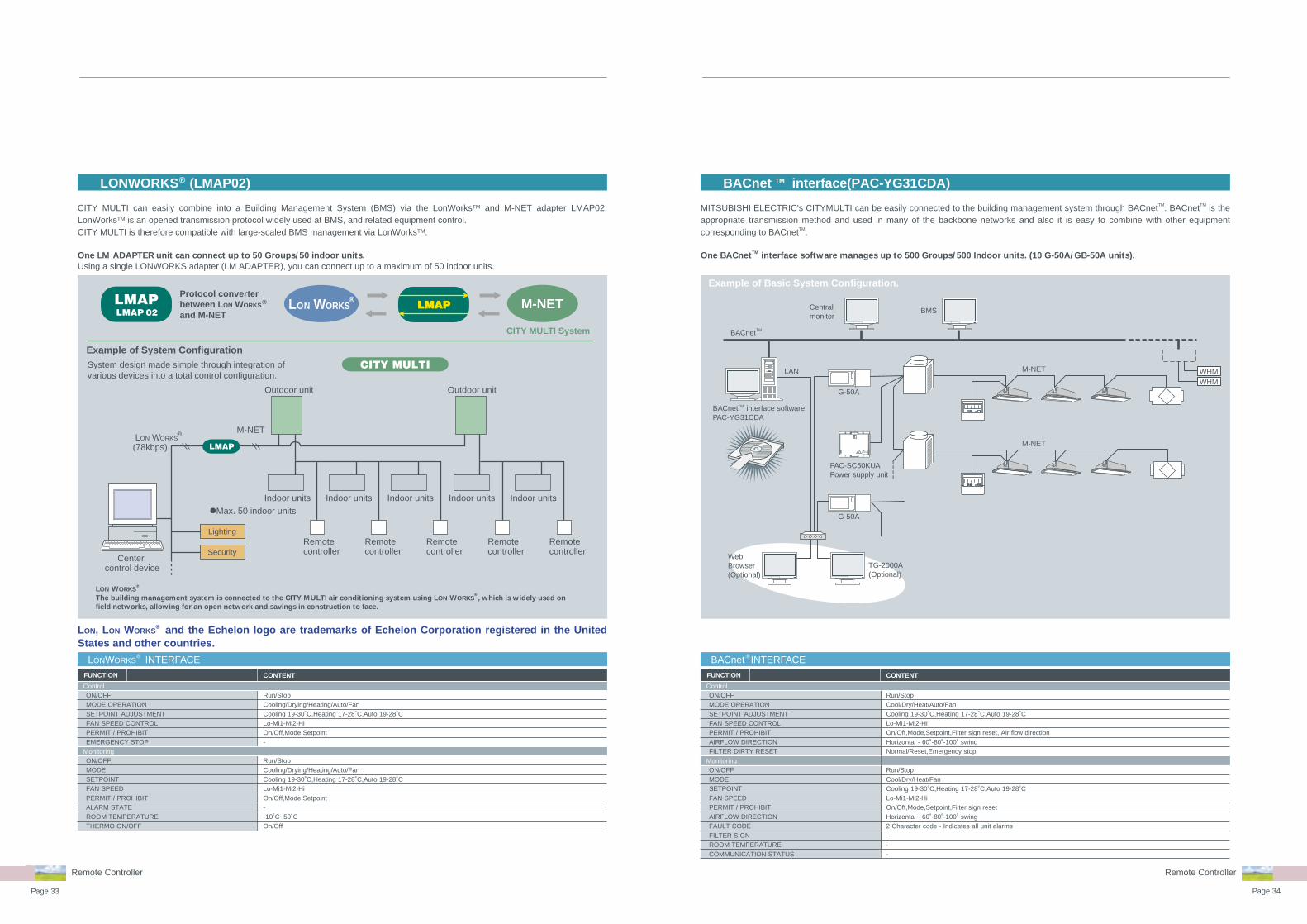
CITY MULTI can easily combine into a Building Management System (BMS) via the LonWorksTM and M-NET adapter LMAP02. LonWorksTM is an opened transmission protocol widely used at BMS, and related equipment control.CITY MULTI is therefore compatible with large-scaled BMS management via LonWorksTM.
One LM ADAPTER unit can connect up to 50 Groups/50 indoor units.
Using a single LONWORKS adapter (LM ADAPTER), you can connect up to a maximum of 50 indoor units.
MITSUBISHI ELECTRIC's CITYMULTI can be easily connected to the building management system through BACnetTM. BACnetTM is the appropriate transmission method and used in many of the backbone networks and also it is easy to combine with other equipment corresponding to BACnetTM.
One BACnetTM
interface software manages up to 500 Groups/500 Indoor units. (10 G-50A/GB-50A units).
Remote ControllerRemote Controller
FUNCTION CONTENT
Run/StopCooling/Drying/Heating/Auto/FanCooling 19-30˚C,Heating 17-28˚C,Auto 19-28˚CLo-Mi1-Mi2-HiOn/Off,Mode,Setpoint-
Run/StopCooling/Drying/Heating/Auto/FanCooling 19-30˚C,Heating 17-28˚C,Auto 19-28˚CLo-Mi1-Mi2-HiOn/Off,Mode,Setpoint--10˚C~50˚COn/Off
ON/OFFMODE OPERATIONSETPOINT ADJUSTMENTFAN SPEED CONTROLPERMIT / PROHIBITEMERGENCY STOP
ON/OFFMODESETPOINTFAN SPEEDPERMIT / PROHIBITALARM STATEROOM TEMPERATURETHERMO ON/OFF
LONWORKS INTERFACE®
Control
Monitoring
FUNCTION CONTENT
Run/StopCool/Dry/Heat/Auto/FanCooling 19-30˚C,Heating 17-28˚C,Auto 19-28˚CLo-Mi1-Mi2-HiOn/Off,Mode,Setpoint,Filter sign reset, Air flow directionHorizontal - 60˚-80˚-100˚ swingNormal/Reset,Emergency stop
Run/StopCool/Dry/Heat/FanCooling 19-30˚C,Heating 17-28˚C,Auto 19-28˚CLo-Mi1-Mi2-HiOn/Off,Mode,Setpoint,Filter sign resetHorizontal - 60˚-80˚-100˚ swing2 Character code - Indicates all unit alarms---
ON/OFFMODE OPERATIONSETPOINT ADJUSTMENTFAN SPEED CONTROLPERMIT / PROHIBITAIRFLOW DIRECTIONFILTER DIRTY RESET
ON/OFFMODESETPOINTFAN SPEEDPERMIT / PROHIBITAIRFLOW DIRECTIONFAULT CODEFILTER SIGNROOM TEMPERATURECOMMUNICATION STATUS
BACnet INTERFACE®
Control
Monitoring

Page 35 Page 36
Indoor unit
I ndoor unit
Ceiling cassette type 4-way airflow
Ceiling cassette type 2-way airflow
Ceiling cassette type 1-way airflow
Ceiling concealed type
Ceiling suspended type
Wall mounted type
Floor standing type
Ceiling cassette (4way air flow)
Ceiling concealed
Ceiling cassette (2way air flow)
Ceiling cassette (1way air flow)
Ceiling suspended
Wall mounted
Floor standing
PKFY-P VBM-E
PFFY-P VLEM-E
PFFY-P VKM-E
PEFY-P VMR-E-L/R
Wide selection of indoor units
PLFY-P VBM-EPLFY-VCM-E
PFFY-P VLRM-E
Model
Capacity
P20 P25 P32 P40 P50
2.2kW 2.8kW 3.6kW 4.5kW 5.6kW
Model
Capacity
P63 P80 P100 P125
7.1kW 9.0kW 11.2kW 14.0kW
Model
Capacity
P20 P25 P32 P40 P50
2.2kW 2.8kW 3.6kW 4.5kW 5.6kW
Model
Capacity
P63 P71 P80 P100 P125
7.1kW 8.0kW 9.0kW 11.2kW 14.0kW
Model
Capacity
P20 P25 P32 P40 P50 P63 P71
2.2kW 2.8kW 3.6kW 4.5kW 5.6kW 7.1kW 8.0kW
Model
Capacity
P80 P100 P125 P140 P200 P250
9.0kW 11.2kW 14.0kW 16.0kW 22.4kW 28.0kW
Model
Capacity
P20 P25 P32 P40 P50 P63 P100
2.2kW 2.8kW 3.6kW 4.5kW 5.6kW 7.1kW 11.2kW
Model
Capacity
P20 P25 P32 P40 P50 P63
2.2kW 2.8kW 3.6kW 4.5kW 5.6kW 7.1kW
Model
Capacity
P20 P25 P32 P40
2.2kW 2.8kW 3.6kW 4.5kW
Model
Capacity
P80 P140 P200 P250
9.0kW 16.0kW 22.4kW 28.0kW
Model
Capacity
P40 P63 P100 P125
4.5kW 7.1kW 11.2kW 14.0kW
OA Processing Units
PEFY-P VML-E
PEFY-P VMH-EPEFY-P VMS-E
PEFY-P VMH-E-F
PLFY-P VLMD-E
PMFY-P VBM-E
PCFY-P VGM-E
Fresh Air Intake
New
New
Page37 - Page38
Page55 - Page56Page39 - Page40
Page57 - Page58Page41 - Page42
Page59 - Page62Page43 - Page52
Page53 - Page54
New
New
New
PKFY-P VGM-E
PKFY-P VFM-E
PDFY-P VM-E
Page 37 Page 38
SpecificationsIndoor unit
PLFY-P VBM-E
PLFY-P VCM-E
INDOOR UNITCeiling cassette type4-way airflow
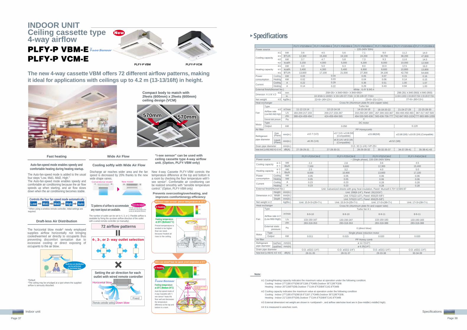
The new 4-way cassette VBM offers 72 different airflow patterns, making it ideal for applications with ceilings up to 4.2 m (13-13/16ft) in height.
Specifications
Note:
PLFY-P32VBM-E PLFY-P40VBM-E PLFY-P50VBM-E PLFY-P63VBM-E
3.612,300
3.73,1504.0
3,40013,6000.030.020.220.14
4.515,400
4.74,0005.0
4,30017,100
5.619,100
5.85,0006.3
5,40021,500
7.124,200
7.36,3008.0
6,90027,3000.050.040.360.29
Power source
Cooling capacity
Heating capacity
Powerconsumption
Current
External finish(Munsel No.)
Dimension H ✕ W ✕ D
Net weightHeat exchanger
Fan
Motor
Air filter
Refrigerantpipe diameter
Drain pipe diameterNoise level (Lo-Mid1-Mid2-Hi) ❇ 3 ❇ 4
Type
Airflow rate(Low-Mid1-Mid2-High)
External static pressureTypeOutput
Gas(Flare)
Liquid(Flare)
0.040.030.29
0.22
22<6> (49<13>)
Turbo fan11-12-13-14 12-13-14-16
ø12.7 (1/2)
14-15-16-18
DC motor
ø6.35 (1/4) ø9.52 (3/8)
O.D. 32 (1-1/4) <VP-25>
27-28-29-31 27-28-30-31 28-29-30-32
ø12.7 (1/2) / ø15.88 (5/8)(Compatible)
ø6.35 (1/4) / ø9.52 (3/8)(Compatible)
258<35> ✕ 840<950> ✕ 840<950>10-3/16<1-13/32> ✕ 33-1/8<37-7/16> ✕ 33-1/8<37-7/16> 11-3/4<1-13/32> ✕ 33-1/8<37-7/16> ✕ 33-1/8<37-7/16>
kWBTU/h
kWkcal/h
kWkcal/hBTU/h
kWkWAA
mmin.
kg(lbs.)
m3/minL/scfmPa
kW
mm(in.)
mm(in.)
mm(in.)dB(A)
❇ 1❇ 1❇ 2❇ 2❇ 1❇ 1❇ 1
❇ 3
❇ 3
❇ 3
PLFY-P80VBM-E PLFY-P100VBM-E PLFY-P125VBM-E
9.030,700
9.38,00010.0
8,60034,1000.070.060.510.43
11.238,20011.6
10,00012.5
10,80042,7000.150.141.000.94
14.047,800
14.512,500
16.013,80054,600
0.160.151.071.00
White : 6.4Y 8.9/0.4
23<6> (51<13>)Cross fin (Aluminum plate fin and copper tube)
16-18-20-22
ø15.88(5/8)
0
0.050 0.120
PP Honeycomb
30-32-35-37
27<6> (60<13>)
21-24-27-29 22-25-28-30
183-200-217-233388-424-459-494
200-217-233-267424-459-494-565
233-250-267-300494-530-565-636
267-300-333-367565-636-706-777
350-400-450-483742-847-953-1024
367-417-467-500777-883-989-1059
34-37-39-41 35-38-41-43
ø15.88 (5/8) / ø19.05 (3/4) (Compatible)
298 (35) ✕ 840 (950) ✕ 840 (950)
~ 220-240V 50Hz
CoolingHeatingCoolingHeating
CoolingHeatingCoolingHeating
❇ 1 Cooling/Heating capacity indicates the maximum value at operation under the following condition.Cooling : Indoor 27˚C(80.6˚F)DB/19˚C(66.2˚F)WB,Outdoor 35˚C(95˚F)DBHeating : Indoor 20˚C(68˚F)DB,Outdoor 7˚C(44.6˚F)DB/6˚C(42.8˚F)WB
❇ 2 Cooling capacity indicates the maximum value at operation under the following conditionCooling : Indoor 27˚C(80.6˚F)DB/19.5˚C(67.1˚F)WB,Outdoor 35˚C(95˚F)DB.Heating : Indoor 21˚C(69.8˚F)DB,Outdoor 7˚C(44.6˚F)DB/6˚C(42.8˚F)WB
❇ 3 External dimension/ net weight are shown in <unit/panel> , and airflow rate/noise level are in (low-middle1-middle2-high).
❇ 4 It is measured in anechoic room.
Compact body to match with 2feets (600mm) x 2feets (600mm) ceiling design (VCM)
570mm570mm570mm570mm 570mm570mm
PLFY-P VBM PLFY-P VCM
PLFY-P20VCM-E PLFY-P25VCM-E PLFY-P32VCM-E PLFY-P40VCM-E
0.050.050.230.23
0.05
~ (Single phase), 220-230-240V 50Hz
Unit: Galvanized sheets with gray heat insulation, Panel: Munsell 0.70Y 8.59/0.97
Unit: 208(8-1/4"), Panel: 20(13/16")
0 (direct blow)
PP Honey comb
Single phase induction motor
Unit: 570(22-1/2"), Panel: 650(25-5/8")
Unit: 570(22-1/2"), Panel: 650(25-5/8")
Cross fin (Aluminum plate fin and copper tube)Turbo fan ¥ 1
0.050.230.23
0.060.060.280.28
0.06
ø 12.7(1/2")
ø 6.35(1/4")
0.060.28
2.2
2.5
2.8
3,2
3.6
4.0
4.57,500 9,600 12,300 15,400
5.08,500 10,900 13,600 17,100
0.28
8-9-10 8-9-10 8-9-11 8-9-11
133-150-167 133-150-167 133-150-183 133-150-183283-318-353 283-318-353 283-318-388 283-318-388
Unit: 15.5<3>(35<7>) Unit: 15.5<3>(35<7>) Unit: 17<3>(38<7>) Unit: 17<3>(38<7>)
Power sourcekW
Cooling capacity ❇ 1
❇ 1
❇ 1
❇ 1kW
Btu/h
Btu/hkWkWAA
mm(in.)mm(in.)mm(in.)kg(lbs.)
L/scfm
m3/min
Pa
kW
mm(in)
mm(in)
dB(A)
Heating capacity
Powerconsumption
Current
External finish(Munsel No.)
Dimension ❇ 2HeightWidthDepth
Net weight ❇ 2Heat exchanger
Fan
Type
External staticpressure
MotorOutputType
Air filter
Refrigerant pipe diameter
Gas(Flare)
Liquid(Flare)Drain pipe diameterNoise level (Lo-Mid-Hi) ❇ 2 ❇ 3
Airflow rate ❇ 2(Low-Mid-High)
0.011 0.015 0.020 0.020
28-31-35 28-31-37 29-33-38 30-34-39O.D. ø32(1-1/4") O.D. ø32(1-1/4") O.D. ø32(1-1/4") O.D. ø32(1-1/4")
Auto-fan-speed mode enables speedy and comfortable heating during heating startup.
The Auto-fan-speed mode is added to the usual four steps “Low, Mid1, Mid2, High.”The Auto-fan-speed mode enables speedy and comfortable air conditioning because the air flow speeds up when starting, and air flow slows down when the air conditioning becomes stable.
Controls the four fan speed mode automaticallyLow High AutoMid2Mid1
* When using a wireless remote controller, initial settings are required.
*Default*The ceiling may be smudged at a spot where the supplied airflow is seriously disturbed.
The horizontal blow mode* newly employed supplies airflow horizontally not bringing cooled/warmed air directly to occupants thus preventing discomfort sensation due to excessive cooling or direct exposing of occupants to the air blow.
Discharge air reaches wider area and the fan speed is decreased by 20% thanks to the new wide shape vanes.
Cooling softly with Wide Air Flow
Conventional model New model
72 patterns of airflow to accommodate any room layout are available.
First in the industry
The number of outlet can be set to 4, 3, or 2. Flexible airflow is available by fixing the up-down airflow direction of the outlet with a wired remote controller (or manually).
72 airflow patterns
4-, 3-, or 2- way outlet selection
Setting the air direction for each outlet with wired remote controller
Down blow
Horizontal blow
Remote controller setting
Fixed
*On the commercial air conditioners (According to the survey by Mitsubishi Electric)
Auto-fan-speed mode of 4-way Cassette with “i-see sensor” heats the floor well and decreases the temperature difference at the top and bottom in a room.
Preset temperature is tended to be higher than we need, because heated air rises to the ceiling.
Feeling temperature at 20˚C (Bottom17˚C)
Feeling temperature at 20˚C (Bottom 20˚C)
37˚C
25˚C
13˚C
37˚C
25˚C
13˚C
New 4-way Cassette PLFY-VBM controls the temperature difference at the top and bottom in a room by checking the floor temperature with“i-see sensor”. Comfortable air conditioning can be realized smoothly with “sensible temperature control.” (Option, PLFY-VBM only)
“i-see sensor” can be used with ceiling cassette type 4-way airflow unit. (Option, PLFY-VBM only)
Prevents overcooling/overheating, and improves comfort/energy-efficiency
Without i-see sensor: preset temperature at 23˚C
With i-see sensor+Auto fan speed: preset temperature at 20˚C
In heating
In heating
Fast heating
Draft-less Air Distribution
Wide Air Flow
New
Draft-less air distributioncan be performed
by horizontal blow.
Suction temperature sensor
The area that the ceilingcassette without“i-see sensor” can monitor.
2.7m
Suction temperature sensor
11.5m11.5m
The area that the ceilingcassette with“i-see sensor” can monitor.360˚360˚

Page 39 Page 40
Specifications
Specifications
Note:
INDOOR UNITCeiling cassette type2-way airflow PLFY-P VLMD-E
Fresh air can be taken in to the main unit directly (optional ac-cessories needed.
The drain can be positioned anywhere up to 600mm(23-5/8in.) from the ceiling's surface, providing greater freedom with long cross-piping and allowing more versatility with piping layouts.
Equipped with drain water lift-up mechanism as standard
Terminal block on outside of main unit makes wiring easier
Newly designed decorative panel with air flow switching and swing functions as a standard feature
Compact unit and low noise level attained! Fresh air directly taken in
The slimline body is highly suitable for installation in narrow ceiling spaces and for replacing obsolete air-conditioning equipment in older buildings. The main unit is only 290mm(11-7/16in.) height.
Slim body - only 290mm(11-7/16in.) height
Ceiling surface
Drain heightmax. 593(23-3/8)
Main unit height - 290(11-7/16)
593
290mm
(11-7/16in.)
Slim body of 290mm(11-7/16in.) height.
❇ 1 Cooling/Heating capacity indicates the maximum value at operation under the following condition.Cooling : Indoor 27˚C(80.6˚F)DB/19˚C(66.2˚F)WB,Outdoor 35˚C(95˚F)DBHeating : Indoor 20˚C(68˚F)DB,Outdoor 7˚C(44.6˚F)DB/6˚C(42.8˚F)WB
❇ 2 Cooling capacity indicates the maximum value at operation under the following condition.Cooling : Indoor 27˚C(80.6˚F)DB/19.5˚C(97.1˚F)WB,Outdoor 35˚C(95˚F)DB Heating : Indoor 21˚C(69.8˚F)DB,Outdoor 7˚C(44.6˚F)DB/6˚C(42.8˚F)WB
❇ 3 The figure in < > indicates panel's
❇ 4 It is measured in anechoic room.
mm (in.)
Indoor unit
PLFY-P20VLMD-E PLFY-P25VLMD-E PLFY-P32VLMD-E PLFY-P40VLMD-E~ 220-240V 50Hz / ~ 220-230V 60Hz
Unit: Galvanizing Decoration Panel: ABS (0.7Y 8.59/0.97) Service Panel: Galvanizing (0.7Y 8.59/0.97)290<20> ✕ 776<1,080> ✕ 634<710>
11-7/16<13/16> ✕ 30-9/16<42-9/16> ✕ 25<28>23 <6.5> (51<15>)
Cross finTurbo fan ✕ 1
0Single phase induction motor
0.015PP honeycomb fabric (long life filter)
ø12.7 (1/2)ø6.35 (1/4)
O.D.32 (1-1/4)
6.5-8.0-9.5108-133-158230-283-335
7.0-8.5-10.5117-142-175247-300-371
24 <6.5> (53<15>)
2.27,5002.3
2,0002.5
2,2008,500
0.072 / 0.0750.065 / 0.0690.36 / 0.370.30 / 0.32
2.89,6002.9
2,5003.2
2,80010,900
0.072 / 0.0750.065 / 0.0690.36 / 0.370.30 / 0.32
3.612,300
3.73,1504.0
3,40013,600
0.072 / 0.0750.065 / 0.0690.36 / 0.370.30 / 0.32
4.515,400
4.74,000
5.04,30017,100
0.081 / 0.0850.074 / 0.079
0.40 / 0.420.34 / 0.37
27-30-3328-31-34
29-33-3630-34-37
kWBTU/h
kWkcal/h
kWkcal/hBTU/h
kWkWAA
mmin.
kg(lbs.)
m3/minL/scfmPa
kW
mm(in.)mm(in.)mm(in.)dB(A)dB(A)
❇ 1❇ 1❇ 2❇ 2❇ 1❇ 1❇ 1
❇ 3
❇ 3
CoolingHeatingCoolingHeating
Type
Airflow rate (Lo-Mid-Hi)
External static pressureTypeOutput
Gas(Flare)Liquid(Flare)
❇ 4220V,240V230V
kWBTU/h
kWkcal/h
kWkcal/hBTU/h
kWkWAA
mmin.
kg(lbs.)
m3/minL/scfmPa
kW
mm(in.)
mm(in.)
mm(in.)dB(A)dB(A)
❇ 1❇ 1❇ 2❇ 2❇ 1❇ 1❇ 1
❇ 3
❇ 3
CoolingHeatingCoolingHeating
TypeAirflow rate(P50~P100:Lo-Mid-Hi)(P125:Lo-Mid2-Mid1-Hi)External static pressureTypeOutput
Gas(Flare)
Liquid(Flare)
❇ 4220V,240V230V
PLFY-P63VLMD-E PLFY-P80VLMD-E PLFY-P100VLMD-E PLFY-P125VLMD-E
~ 220-240V 50Hz / ~ 220-230V 60Hz
Unit: Galvanizing Decoration Panel: ABS (0.7Y 8.59 / 0.97) Service Panel: Galvanizing (0.7Y 8.59 / 0.97)
Turbo fan ✕ 1 Turbo fan ✕ 2
ø15.88 (5/8)
ø9.52 (3/8)
10.0-13.0-15.5167-217-258353-459-547
17.5-21.0-25.0292-350-417618-742-883
0.030 (at 240V)
15.5-18.5-22.0258-308-367547-653-777
0Single phase induction motor
0.020 (at 240V)0.020
7.124,200
7.36,3008.0
6,90027,300
0.101 / 0.1050.094 / 0.0990.49 / 0.510.43 / 0.46
28 <7.5> (62<17>)
9.030,700
9.38,00010.0
8,60034,100
0.147 / 0.1560.140 / 0.1500.72 / 0.740.66 / 0.69
44 <12.5> (98<28>)Cross fin
11.238,20011.6
10,00012.5
10,80042,700
0.157 / 0.1860.150 / 0.1800.75 / 0.880.69 / 0.83
47 <12.5> (104<28>)
14.047,800
14.512,500
16.013,80054,600
0.28 / 0.280.27 / 0.271.35 / 1.351.33 / 1.33
290<20> ✕ 1,708<2,010> ✕ 606<710>11-7/16<13/16> ✕ 67-1/4<79-3/16> ✕ 23-7/8< 28>
56 <13.0> (124<29>)
Sirocco fan ✕ 424.0-27.0-30.0-33.0
400-450-500-550848-953-1,059-1,165
0.078 ✕ 2 (at 240V)Synthetic fiber unwoven
cloth filter (long life)
O.D.32 (1-1/4)33-36-3934-37-40
PLFY-P50VLMD-E
PP honeycomb fabric (long life filter)
5.619,100
5.85,0006.3
5,40021,500
0.082 / 0.0860.075 / 0.0800.41 / 0.430.35 / 0.38
27 <7.5> (60<17>)
31-34-3732-35-38
32-37-3933-38-40
40-42-44-46(Lo-Mid2-Mid1-Hi)
ø15.88 (5/8)ø12.7 (1/2)
ø 6.35 (1/4)
36-39-4237-41-43
290<20> ✕ 946<1,250> ✕ 634<710>11-7/16<13/16> ✕ 37-1/4<49-1/4> ✕ 25< 28>
290<20> ✕ 1,446<1,750> ✕ 634<710>11-7/16<13/16> ✕ 56-15/16<68-15/16> ✕ 25< 28>
9.0-11.0-12.5150-183-208318-388-441
Power source
Cooling capacity
Heating capacity
Powerconsumption
Current
External finish
Dimension H ✕ W ✕ D
Net weightHeat exchanger
Fan
Motor
Air filterRefrigerantpipe diameterDrain pipe diameterNoise level(Lo-Mid-Hi)
Power source
Cooling capacity
Heating capacity
Powerconsumption
Current
External finish
Dimension H ✕ W ✕ D
Net weightHeat exchanger
Fan
Motor
Air filter
Refrigerantpipe diameter
Drain pipe diameterNoise level(Lo-Mid-Hi)

Page 41 Page 42
Specifications
Specifications
Note:
❇ 1 Cooling/Heating capacity indicates the maximum value at operation under the following condition.Cooling : Indoor 27˚C(80.6˚F)DB/19˚C(66.2˚F)WB,Outdoor 35˚C(95˚F)DBHeating : Indoor 20˚C(68˚F)DB,Outdoor 7˚C(44.6˚F)DB/6˚C(42.8˚F)WB
❇ 2 Cooling capacity indicates the maximum value at operation under the following condition.Cooling : Indoor 27˚C(80.6˚F)DB/19.5˚C(67.1˚F)WB,Outdoor 35˚C(95˚F)DBHeating : Indoor 21˚C(69.8˚F)DB,Outdoor 7˚C(44.6˚F)DB/6˚C(42.8˚F)WB
❇ 3 External dimension / net weight are shown in <panel>, and airflow rate/noise level are in (low-middle2-middle1-high).
❇ 4 It is measured in anechoic room.
mm (in.)
198(7-13/16)
PMFY-VBM230
(9-11/16)
max.402
(15-7/8)max.600
(23-5/8)
Compact and lightweight body perfect for limited ceiling space applications.
Unit body size has been standardized for all models at 854mm for easier installa-tion. Body weight is only 14kg for the main unit and 3kg for the panel, making this unit one of the lightest in the industry.
Compact size for smooth installation and maintenance
Newly developed airflow control technolo-gy reduces noise level to only 27dB (P20VBM) for industry-leading quiet oper-ation.
Quiet operation
The drain can be positioned anywhere up to 600mm(23-5/8in.) from the ceiling's surface.
Drain lift-up mechanism
PMFY-P VBM-E
INDOOR UNITCeiling cassette type1-way airflow
Indoor unit
Power source
Cooling capacity
Heating capacity
Powerconsumption
Current
External finishDimension H ✕ W ✕ DNet weightHeat exchanger
Fan
Motor
Air filterRefrigerantpipe diameterDrain pipe diameterNoise level (Lo-Mid2-Mid1-Hi)
0.0440.0440.210.21
Panel : 0.98Y8.99/0.63230<30> ✕ 812<1,000> ✕ 395<470> (9-1/16<1-3/16> ✕ 32<39-3/8> ✕ 15-9/16<18-9/16>)
14 <3.0> (31<7>)Cross fin (Aluminum plate fin and copper tube)
Line flow fan ✕ 17.3-8.0-8.6-9.3
122-133-143-155258-283-304-328
0Single phase induction motor
0.028PP Honeycomb fabric
ø12.7 (1/2)ø6.35 (1/4)
O.D. 25 (1) <VP-20>32-34-36-37
4.515,400
4.74,000
5.04,30017,1000.0540.0540.260.26
7.7-8.7-9.7-10.7128-145-162-178272-307-343-378
33-35-37-39
kWBTU/h
kWkcal/h
kWkcal/hBTU/h
kWkWAA
mm(in.)kg(lbs.)
m3/minL/scfmPa
kW
mm(in.)mm(in.)mm(in.)dB(A)
Type
Airflow rate(Low-Mid2-Mid1-High)
External staticpressureTypeOutput
CoolingHeatingCoolingHeating
❇ 1❇ 1❇ 2❇ 2❇ 1❇ 1❇ 1
❇ 3
❇ 3
❇ 3
❇ 4
Gas(Flare)Liquid(Flare)
2.89,6002.9
2,5003.2
2,80010,900
2.27,5002.3
2,0002.5
2,2008,5000.0420.0420.200.20
3.612,300
3.73,1504.0
3,40013,600
~ 220-240V 50Hz / ~ 220V 60Hz
6.5-7.2-8.0-8.7108-120-133-145230-254-283-307
27-30-33-35
PMFY-P25VBM-E PMFY-P32VBM-E PMFY-P40VBM-EPMFY-P20VBM-E

Page 43 Page 44
Specifications
INDOOR UNITCeiling concealedtypePEFY-P VMR-E-L/R
Prepared a contact for a card key. It is possible to operate / stop by taking a card key in and out.
Realizing the low level noise that is NC21 around a bed and N22 around a desk when the high notch.It contributes to create a quiet indoor environment.*Outlet is elbow-constructed using a glass wool duct.The noise level is changed by the room size or the setting con-dition of the unit.
Operable by card key switch Ultra low noise
Energy-saving by prevention of forgetting the switch off
Enables to install for symmetric design room
Both of Left piping / Right piping, control box, are available.It's selectable for layout of each room.Plus easy maintenance from the access door in the prefabrica-ted bath.*Seen from an anterior view, the pipe and control box are on the right side of –R type.
Compact & Simple operation remote controller is available.*This remote controller can operate only start / stop, indoor tem-perature control and wind speed control. Centralized remote controller must be used together.Prevents forgetting of switch off by a centralized remote control-ler like G-50.
Problem solver for residential hotels, museums, libraries, or hospitals where low noise is especially a must!
Noise measurement pointNoise measurement pointNoise measurement pointCard KeySwitchCard KeySwitch
InletInlet
Noise measurement pointNoise measurement pointNoise measurement point
*According to the data measured in Mitsubishi Electric laboratory
New
Indoor unit
Specifications
Note:
❇ 1 Cooling/Heating capacity indicates the maximum value at operation under the following condition.Cooling : Indoor 27˚C (81˚F) DB/19˚C (66˚F) WB, Outdoor 35˚C (95˚F) DBHeating : Indoor 20˚C (68˚F) DB, Outdoor 7˚C (45˚F) DB/6˚C (43˚F) WB
❇ 2 Cooling capacity indicates the maximum value at operation under the following condition.Cooling : Indoor 27˚C (80.6˚F) DB/19.5˚C (67.1˚F) WB,Outdoor 35˚C (95˚F) DB Heating : Indoor 21˚C (69.8˚F) DB,Outdoor 7˚C (44.6˚F) DB/6˚C (42.8˚F) WB
❇ 3 The external static pressure is set to 100Pa (at 220V) / 150Pa (at 230, 240V) at factory shipment.
❇ 4 Measured in anechoic room. Noise levels of the unit with a rear air inlet. (Noise levels are higher than the unit with a bottom air inlet.)
Static Presure
5Pa
Width
640mm25-6/32in.
Ultra Low Noise
Piping connectionL modelR model
0.018 0.023
Power source
Cooling capacity
Heating capacity
Powerconsumption
Current
External finish
Dimension H ✕ W ✕ D
Net weightHeat exchanger
Fan
Motor
Air filter
Refrigerantpipe diameter
Drain pipe diameter
Noise level (Lo-Mid-Hi) ❇ 4
Gas(Flare)Liquid(Flare)
220V230V240V
TypeAirflow rate(Lo-Mid2-Mid1-Hi)External staticpressureTypeOutput
CoolingHeatingCoolingHeating
kWBTU/h
kWkcal/h
kWkcal/hBTU/h
kWkWAA
mmin.
kg(lbs.)
m3/min
Pa
kW
mm(in.)
mm(in.)
mm(in.)
dB(A)
❇ 1❇ 1❇ 2❇ 2❇ 1❇ 1❇ 1
❇ 3
❇ 3
1-phase 220/230/240V 50Hz 220/230V 60Hz2.8
9,6002.9
2,5003.2
2,80010,900
0.06 / 0.060.06 / 0.060.29 / 0.290.29 / 0.29Galvanized
292 ✕ 640 ✕ 580-
18 (40)Cross fin (Aluminum fin and copper tube)
Sirocco fan ✕ 1
PEFY-P20VMR-E-L PEFY-P25VMR-E-L PEFY-P32VMR-E-L
2.27,5002.3
2,0002.5
2,2008,500
0.06 / 0.060.06 / 0.060.29 / 0.290.29 / 0.29
3.612,300
3.73,150
4.03,40013,600
0.07 / 0.080.07 / 0.080.34 / 0.380.34 / 0.38
5
1-phase induction motor
PP Honeycomb fabric (washable)
ø6.35 (1/4)
ø12.7(1/2)
O.D. 26 (1)
4.8-5.8-7.9 4.8-5.8-9.3
20-25-3021-26-3222-27-30
20-25-3321-26-3522-27-33
0.018 0.023
Power source
Cooling capacity
Heating capacity
Powerconsumption
Current
External finish
Dimension H ✕ W ✕ D
Net weightHeat exchanger
Fan
Motor
Air filter
Refrigerantpipe diameter
Drain pipe diameter
Noise level (Lo-Mid-Hi) ❇ 4
Gas(Flare)Liquid(Flare)
220V230V240V
TypeAirflow rate(Lo-Mid2-Mid1-Hi)External staticpressureTypeOutput
CoolingHeatingCoolingHeating
kWBTU/h
kWkcal/h
kWkcal/hBTU/h
kWkWAA
mmin.
kg(lbs.)
m3/min
Pa
kW
mm(in.)
mm(in.)
mm(in.)
dB(A)
❇ 1❇ 1❇ 2❇ 2❇ 1❇ 1❇ 1
❇ 3
❇ 3
1-phase 220/230/240 V 50Hz 220/230V 60Hz2.8
9,6002.9
2,5003.2
2,80010,900
0.06 / 0.060.06 / 0.060.29 / 0.290.29 / 0.29Galvanized
292 ✕ 640 ✕ 580-
18 (40)Cross fin (Aluminum fin and copper tube)
Sirocco fan ✕ 1
PEFY-P20VMR-E-R PEFY-P25VMR-E-R PEFY-P32VMR-E-R
2.27,5002.3
2,0002.5
2,2008,500
0.06 / 0.060.06 / 0.060.29 / 0.290.29 / 0.29
3.612,300
3.73,150
4.03,40013,600
0.07 / 0.080.07 / 0.080.34 / 0.380.34 / 0.38
5
1-phase induction motor
PP Honeycomb fabric (washable)
ø6.35 (1/4)
ø12.7 (1/2)
O.D. 26(1)
4.8-5.8-7.9 4.8-5.8-9.3
20-25-3021-26-3222-27-30
20-25-3321-26-3522-27-33
Page 45 Page 46
Specifications
SpecificationsNew
Note:
❇ 1 Cooling/Heating capacity indicates the maximum value at operation under the following condition.Cooling : Indoor : 27˚CD.B./19˚CW.B. (81˚FD.B. / 66˚FW.B.) Outdoor : 35˚CD.B. (95˚FD.B. )Heating : Indoor : 20˚CD.B. (68˚FD.B.) Outdoor : 7˚CD.B. / 6˚CW.B. (45˚FD.B. / 43˚FW.B.)
Pipe length : 7.5m (24-9/16ft) Height difference : 0m (0ft)
❇ 2 Cooling Indoor: 27˚C(80.6˚F)DB/19.5˚C(67.1˚F)WB, Outdoor: 35˚C(95˚F)DBHeating Indoor: 21˚C(69.8˚F)DB, Outdoor: 7˚C(44.6˚F)DB/6˚C(42.8˚F)WB
❇ 3 The external static pressure is set to 15 Pa at factory shipment.
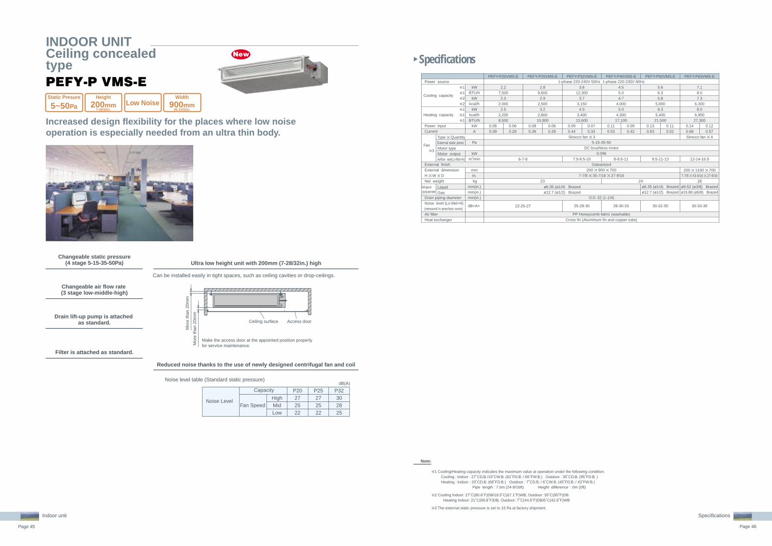
Increased design flexibility for the places where low noise operation is especially needed from an ultra thin body.
Changeable static pressure(4 stage 5-15-35-50Pa)
Can be installed easily in tight spaces, such as ceiling cavities or drop-ceilings.
Ultra low height unit with 200mm (7-28/32in.) high
PEFY-P VMS-E
INDOOR UNITCeiling concealedtype
Changeable air flow rate (3 stage low-middle-high)
Drain lift-up pump is attached as standard.
Filter is attached as standard.
Reduced noise thanks to the use of newly designed centrifugal fan and coil
dB(A)Noise level table (Standard static pressure)
Mor
e th
an 2
0mm
Mor
e th
an 2
0mm
Make the access door at the appointed position properlyfor service maintenance.
Ceiling surface Access door
P20272522
Capacity P25272522
P32302825
Noise LevelHighMidLow
Fan Speed
Indoor unit
Static Presure
5~50Pa
Height
200mm7-28/32in.
Width
900mm35-14/32in.
Low Noise
0.080.39
2.27,5002.3
2,0002.5
2,2008,500
0.060.28
0.080.39
0.060.28
0.090.44
0.070.33
0.110.53
0.090.42
0.130.63
0.110.52
0.140.68
0.120.57
kW
BTU/hkW
kcal/hkW
kcal/hBTU/h
kWA
Pa
kWm3/min
mmIn. kg
mm(in.)mm(in.)mm(in.)
dB<A>
Power source
Cooling capacity
Heating capacity
Power input Current
Fan ❇ 3
External finish External dimension H ✕ W ✕ D Net weight
Drain piping diameter Noise level (Lo-Mid-Hi) (mesured in anechoic room) Air filter Heat exchanger
Type ✕ Quantity External static press Motor type Motor output Airflow rate(Lo-Mid-Hi)
Liquid Gas
1-phase 220-240V 50Hz 1-phase 220-230V 60Hz
5-15-35-50DC brushless motor
0.096
Galvanized200 ✕ 900 ✕ 700
7-7/8 ✕ 35-7/16 ✕ 27-9/16
O.D. 32 (1-1/4)
PP Honeycomb fabric (washable)Cross fin (Aluminium fin and copper tube)
3.612,300
3.73,1504.0
3,40013,600
Sirocco fan ✕ 3
7.5-8.5-10
25-28-30
ø6.35 (ø1/4) Brazedø12.7 (ø1/2) Brazed
2.89,6002.9
2,5003.2
2,80010,900
23 24
4.55.04.7
4,0005.0
4,30017,100
8-9.5-11
28-30-33
5.66.35.8
5,0006.3
5,40021,500
9.5-11-13
ø6.35 (ø1/4) Brazedø12.7 (ø1/2) Brazed
30-32-35
6-7-8
22-25-27
7.18.07.3
6,3008.0
6,90027,300
Sirocco fan ✕ 4
12-14-16.5
200 ✕ 1100 ✕ 7007-7/8 ✕ 43-5/16 ✕ 27-9/16
28ø9.52 (ø3/8) Brazedø15.88 (ø5/8) Brazed
30-33-36
PEFY-P20VMS-E PEFY-P25VMS-E PEFY-P32VMS-E PEFY-P50VMS-EPEFY-P40VMS-E PEFY-P63VMS-E
❇ 1❇ 1❇ 2❇ 2❇ 1❇ 1❇ 1
Refrigerant piping diameter

Page 47 Page 48
Specifications
Specifications
Note: In the case of bottom inlet, the operating noise is louder than in the case of rear inlet.
Hole pitch
Access door
20/25/32 Model
100(3-15/16) or more
225(8-7/8)
30(1-3/16)
mm (in.)
20(13/16) or more
Service space:500(19-11/16) or more
245(9-11/16)+Drain covering configurationheight
P20
36
29
25
Capacity P25
36
29
25
P32
40
29
25
NoiseLevel
dB(A)Noise level table
High
Mid
Low
FanSpeed
PEFY-P VML-E
Increased design flexibility for hotel and residential use from a thin body.
Reduced noise thanks to the use of newly designed centrifugal fan
Drainage lines may be connected on either the right or left side.
Low static pressure (5Pa) meets an application requiring direct air flow
Changeable air flow rate (3 stage low-middle-high)
Flexible installation by rear or bottom return air inlet.
Perfect for use in hotels and other places where line placement is a problem.
Filter is attached as standard.
Can be installed easily in tight spaces, such as ceiling cavities or drop-ceilings.Notes: Drain lift-up pump not applicable.
Low height unit with 225mm(8-7/8in.)
Indoor unit
Note:
Cooling/heating capacity indicates the maximum value at operation under the following condition.
❇ 1 Cooling/heating capacity indicates the maximum value at operation under the following condition.Cooling Indoor: 27˚C(80.6˚F)DB/19˚C(66.2˚F)WB, Outdoor: 35˚C(95˚F)DBHeating Indoor: 20˚C(68˚F)DB, Outdoor: 7˚C(44.6˚F)DB/6˚C(42.8˚F)WB
❇ 2 Cooling capacity indicates the maximum value at operation under the following condition.Cooling Indoor: 27˚C(80.6˚F)DB/19.5˚C(67.1˚F)WB, Outdoor: 35˚C(95˚F)DBHeating Indoor: 21˚C(69.8˚F)DB, Outdoor: 7˚C(44.6˚F)DB/6˚C(42.8˚F)WB
❇ 3 The external static pressure is set to 100Pa (at 220V) /150Pa (at 230, 240V) at factory shipment.
❇ 4 The value are that at 240V.
❇ 5 It is measured in anechoic room.
Static Presure
5Pa
Width
720mm28-11/32in.
Power source
Cooling capacity
Heating capacity
Power consumption(50/60Hz)
Current
External finish
Dimension H ✕ W ✕ D
Net weightHeat exchanger
Fan
Motor
Air filter
Refrigerantpipe diameter
Drain pipe diameterNoise level (Lo-Mid-Hi) ❇ 5
Gas(Brazing)Liquid(Brazing)
Type
Airflow rate(Lo-Mid-Hi)
External static pressureTypeOutput
CoolingHeatingCoolingHeating
kWBTU/h
kWkcal/h
kWkcal/hBTU/h
kWkWAA
mmin.
kg(lbs.)
m3/minL/scfmPa
kW
mm(in.)
mm(in.)
dB(A)
❇ 1❇ 1❇ 2❇ 2❇ 1❇ 1❇ 1
PEFY-P20VML-E PEFY-P25VML-E PEFY-P32VML-E
2.27,5002.3
2,0002.5
2,2008,500
~ 220-240V 50Hz / 60Hz2.8
9,6002.9
2,5003.2
2,80010,900
Galvanizing225 ✕ 720 ✕ 550
8-7/8 ✕ 28-3/8 ✕ 21-11/1618 (40)
Cross fin (Aluminum plate fin and copper tube)Sirocco fan ✕ 1
5Single phase induction motor
PP Honeycomb fabric (washable)
ø12.7 (1/2)
ø6.35 (1/4)
R1 (External thread)
0.05 / 0.060.05 / 0.060.24 / 0.280.24 / 0.28
3.612,300
3.73,150
4.03,40013,600
0.07 / 0.090.07 / 0.090.32 / 0.420.32 / 0.42
4.8-5.8-9.580-97-158
170-205-335
0.032
25-29-40
0.023
25-29-36
4.8-5.8-7.980-97-132
170-205-279
INDOOR UNITCeiling concealedtype

Page 49 Page 50
Specifications
Specifications
Note:
Cooling/heating capacity indicates the maximum value at operation under the following condition.
❇ 1 Cooling Indoor: 27˚C(80.6˚F)DB/19˚C(66.2˚F)WB, Outdoor: 35˚C(95˚F)DBHeating Indoor: 20˚C(68˚F)DB, Outdoor: 7˚C(44.6˚F)DB/6˚C(42.8˚F)WB
❇ 2 Cooling Indoor: 27˚C(80.6˚F)DB/19.5˚C(67.1˚F)WB, Outdoor: 35˚C(95˚F)DBHeating Indoor: 21˚C(69.8˚F)DB, Outdoor: 7˚C(44.6˚F)DB/6˚C(42.8˚F)WB
❇ 3 The external static pressure is set to 50Pa at factory shipment.
❇ 4 The value for Models 20-80 are that at the external static pressure of 100Pa, while the value for Models 100-125 are that at the external static pressure of 130Pa.
❇ 5 The figure in ( ) indicates noise level at 240V/50Hz.
❇ 6 It is measured in anechoic room.
Long room
L-shaped roomsRoom with fixed ceiling fixtures
Max.600
(23-5/8)
110-300
(4-3/8~11-13/16)
mm (in.)
Maintenance panelwith air intake Maintenance panel
with air intake
Canvas duct forbottom section
A rear intake canalso be used
Maintenance panelMaintenance panel
Square duct flange Rear intake filter box
A bottom intake canalso be used
Rear intake filter box
System ceiling
Square duct flange
Blower unit(With auto-vanes)
Maintenancepanel withair intake
PDFY-P VM-E
INDOOR UNITCeiling Concealed Type
Achieving creative air conditioning design through a rich array of system materials.
Multiple installation patterns for assorted applications and locationsAir outlet side compatible
with a variety of ducts (optional)
Slim 295mm main unit with optional drain up mechanism ensures
up to 600 mm(23-5/8in.) of lift
Adjustable setting of external static pressure to meet system configuration
and installation conditions
Static pressure settings can be increased to adjust to all kinds of ducts as well as functional upgrade option (high perfor-mance filter etc). An increase from the standard 50Pa to 130 Pa is possible to cope with various layout configurations.*For P100~P125
Flexible installation for a variety of layouts
Indoor unit
Max.416(16-7/16)
184(16-7/16)
Bottom intake (using canvas duct)
Ceiling chamber system (1)
Hanging ceiling installation
Bottom intake (directly attached to panel)
All-duct system
Ceiling chamber system (2)
Static Presure
30~100(130)Pa
Gas(Flare)Liquid(Flare)
TypeAirflow rate(Lo-Mid2-Mid1-Hi)External staticpressureTypeOutput
CoolingHeatingCoolingHeating
kWBTU/h
kWkcal/h
kWBTU/h
kWkcal/h
kWkWAA
mmin.
kg(lbs)
m3/min
Pa
kW
mm(in.)
mm(in.)
mm(in.)dB(A)
Power source
Cooling capacity
Heating capacity
Power consumption(50/60Hz)
Current
External finish
Dimension H ✕ W ✕ D
Net weightHeat exchanger
Fan
Motor
Air filter
Refrigerantpipe diameter
Drain pipe diameterNoise level (Lo-Mid2-Mid1-Hi) ❇ 6
0.13 / 0.150.13 / 0.150.60 / 0.710.60 / 0.71
295 ✕ 960 ✕ 73511-5/8 ✕ 37-13/16 ✕ 28-15/16
Sirocco fan ✕ 2
10.0-11.0-12.5-14.0
34-36-37-39
2.27,5002.3
2,0002.5
8,5002.6
2,250
2.89,6002.9
2,5003.2
10,9003.3
2,8000.11 / 0.120.11 / 0.120.53 / 0.580.53 / 0.58
295 ✕ 710 ✕ 73511-5/8 ✕ 28 ✕ 28-15/16
Sirocco fan ✕ 1
6.0-6.5-7.5-8.5
28-30-33-36
25.5 (57)
ø12.7 (1/2)
ø6.35 (1/4)
ø12.7 (1/2)
ø6.35 (1/4)
~ 220-240V 50Hz / ~ 220V 60Hz3.6
12,3003.7
3,1504.0
13,6004.1
3,550
Galvanizing
27 (60)Cross fin (Aluminum plate fin and copper tube)
30 / 50 / 100
Single phase induction motor0.075 (at 240V)
Synthethic fiber unwoven cloth filter (long life)
O.D. 32 (1-1/4) <VP-25>
5.619,100
5.85,000
6.321,500
6.55,600
34 (75)
4.515,400
4.74,0005.0
17,1005.2
4,500
32 (71)
❇ 1❇ 1❇ 2❇ 2❇ 1❇ 1❇ 2❇ 2
❇ 3
❇ 4❇ 5
Gas(Flare)Liquid(Flare)
TypeAirflow rate(Lo-Mid2-Mid1-Hi)External staticpressureTypeOutput
CoolingHeatingCoolingHeating
kWBTU/h
kWkcal/h
kWBTU/h
kWkcal/h
kWkWAA
mmin.
kg(lbs)
m3/min
Pa
kW
mm(in.)
mm(in.)
mm(in.)dB(A)
Power source
Cooling capacity
Heating capacity
Powerconsumption
Current
External finish
Dimension H ✕ W ✕ D
Net weightHeat exchanger
Fan
Motor
Air filter
Refrigerantpipe diameter
Drain pipe diameterNoise level (Lo-Mid2-Mid1-Hi) ❇ 6
7.124,200
7.36,3008.0
27,3008.3
7,1000.14 / 0.170.14 / 0.170.68 / 0.820.68 / 0.82
12.5-14.0-16.0-18.0
30-34-36-39
8.027,300
8.37,1009.0
30,7009.3
8,0000.15 / 0.180.15 / 0.180.72 / 0.880.72 / 0.88
295 ✕ 1,160 ✕ 73511-5/8 ✕ 45-11/16 ✕ 28-15/16
39 (86)
13.5-15.5-17.5-19.5
30 / 50 / 100
0.078 (at 240V)
ø15.88 (5/8)
32-35-37-40
~ 220-240V 50Hz / ~ 220V 60Hz9.0
30,7009.3
8,00010.0
34,10010.5
9,0000.17 / 0.210.17 / 0.210.82 / 1.010.82 / 1.01Galvanizing
Cross fin (Aluminum plate fin and copper tube)Sirocco fan ✕ 2
14.5-16.5-18.5-21.0
Single phase induction motor
Synthethic fiber unwoven cloth filter (long life)
ø9.52 (3/8)
O.D. 32 (1-1/4) <VP-25>34-37-40-42
14.047,800
14.512,500
16.054,600
16.314,000
0.33-0.38 / 0.390.33-0.38 / 0.391.55-1.63 / 1.841.55-1.63 / 1.84
24.0-34.0(Lo-Hi)
0.190 (at 240V)
40-45 (42-46) ❇ 5
11.238,20011.6
10,00012.5
42,70013.0
11,2000.27-0.31 / 0.290.27-0.31 / 0.291.28-1.34 / 1.361.28-1.34 / 1.36
19.5-28.0(Lo-Hi)
0.140 (at 240V)
34-42 (37-44) ❇ 5
335 ✕ 1,510 ✕ 77513-1/4 ✕ 59-1/2 ✕ 30-9/16
52 (115)
50 / 100 / 130
ø 15.88 (5/8)
❇ 1❇ 1❇ 2❇ 2❇ 1❇ 1❇ 2❇ 2
❇ 3
❇ 4
PDFY-P20VM-E PDFY-P25VM-E PDFY-P32VM-E PDFY-P40VM-E PDFY-P50VM-E
PDFY-P63VM-E PDFY-P71VM-E PDFY-P80VM-E PDFY-P100VM-E PDFY-P125VM-E
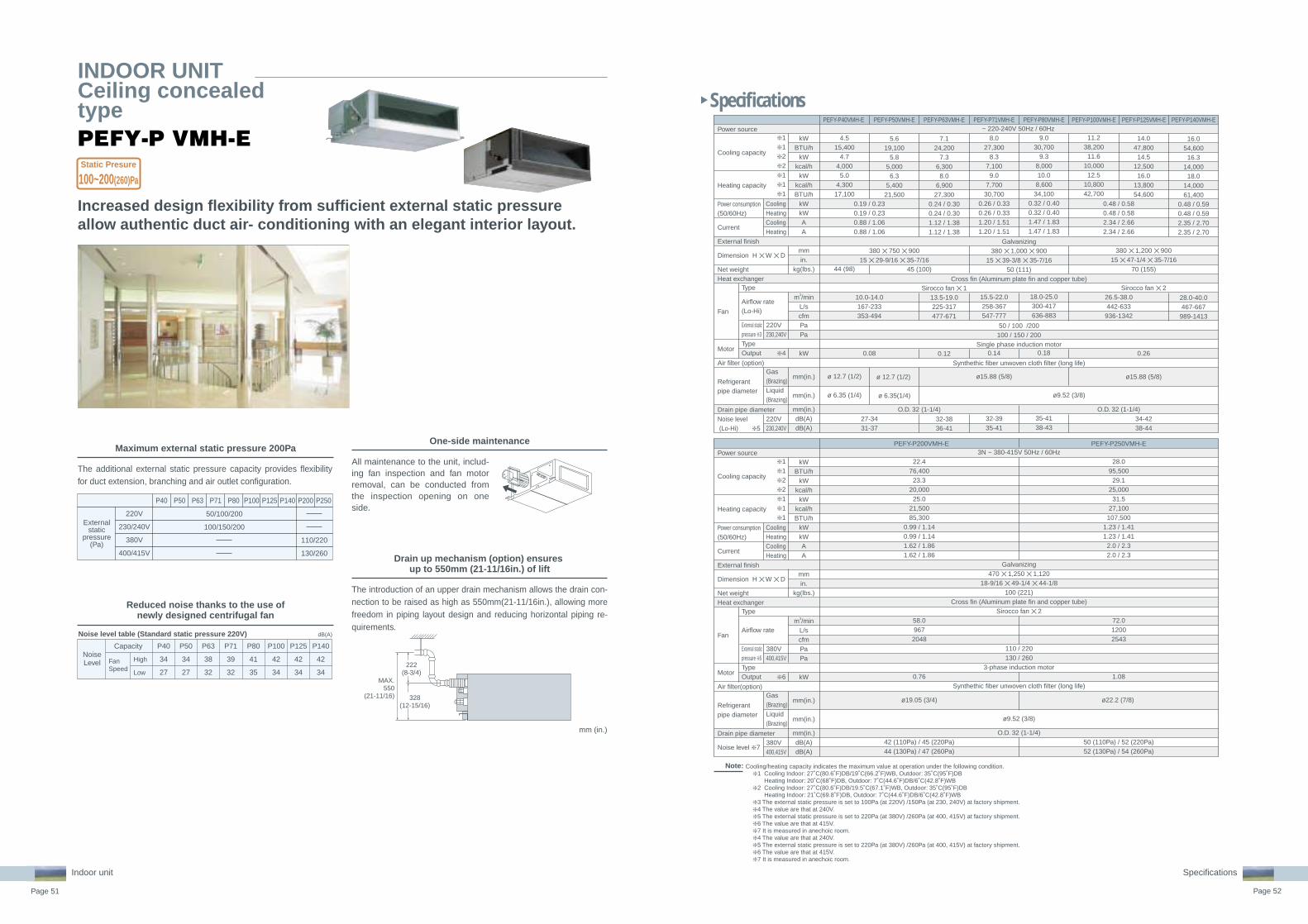
Page 51 Page 52
Specifications
Specifications
Note:
Capacity P50
34
27
P63
38
32
P71
39
32
P80
41
35
P100
42
34
P125
42
34
P140
42
34
NoiseLevel
dB(A)Noise level table (Standard static pressure 220V)
High
Low
P40
34
27
Externalstatic
pressure(Pa)
220V
230/240V
380V
400/415V
P40 P50 P63 P71
50/100/200
100/150/200
110/220
130/260
P80 P100 P125 P140 P200 P250
MAX.550
(21-11/16)
222(8-3/4)
328(12-15/16)
Increased design flexibility from sufficient external static pressure allow authentic duct air- conditioning with an elegant interior layout.
Maximum external static pressure 200Pa
Reduced noise thanks to the use ofnewly designed centrifugal fan
The additional external static pressure capacity provides flexibility for duct extension, branching and air outlet configuration.
Drain up mechanism (option) ensures up to 550mm (21-11/16in.) of lift
The introduction of an upper drain mechanism allows the drain con-nection to be raised as high as 550mm(21-11/16in.), allowing more freedom in piping layout design and reducing horizontal piping re-quirements.
PEFY-P VMH-E
All maintenance to the unit, includ-ing fan inspection and fan motor removal, can be conducted from the inspection opening on one side.
One-side maintenance
FanSpeed
Indoor unit
Cooling/heating capacity indicates the maximum value at operation under the following condition.❇ 1 Cooling Indoor: 27˚C(80.6˚F)DB/19˚C(66.2˚F)WB, Outdoor: 35˚C(95˚F)DB
Heating Indoor: 20˚C(68˚F)DB, Outdoor: 7˚C(44.6˚F)DB/6˚C(42.8˚F)WB❇ 2 Cooling Indoor: 27˚C(80.6˚F)DB/19.5˚C(67.1˚F)WB, Outdoor: 35˚C(95˚F)DB
Heating Indoor: 21˚C(69.8˚F)DB, Outdoor: 7˚C(44.6˚F)DB/6˚C(42.8˚F)WB❇ 3 The external static pressure is set to 100Pa (at 220V) /150Pa (at 230, 240V) at factory shipment. ❇ 4 The value are that at 240V.❇ 5 The external static pressure is set to 220Pa (at 380V) /260Pa (at 400, 415V) at factory shipment.❇ 6 The value are that at 415V.❇ 7 It is measured in anechoic room.❇ 4 The value are that at 240V.❇ 5 The external static pressure is set to 220Pa (at 380V) /260Pa (at 400, 415V) at factory shipment.❇ 6 The value are that at 415V.❇ 7 It is measured in anechoic room.
mm (in.)
Static Presure
100~200(260)Pa
Power source
Cooling capacity
Heating capacity
Power consumption(50/60Hz)
Current
External finish
Dimension H ✕ W ✕ D
Net weightHeat exchanger
Fan
Motor
Air filter (option)
Refrigerantpipe diameter
Drain pipe diameterNoise level (Lo-Hi) ❇ 5
Gas(Brazing)Liquid(Brazing)
220V230,240V
220V230,240V
Type
Airflow rate(Lo-Hi)
External staticpressure ❇ 3TypeOutput
CoolingHeatingCoolingHeating
kWBTU/h
kWkcal/h
kWkcal/hBTU/h
kWkWAA
mmin.
kg(lbs.)
m3/minL/scfmPaPa
kW
mm(in.)
mm(in.)
mm(in.)dB(A)dB(A)
❇ 1❇ 1❇ 2❇ 2❇ 1❇ 1❇ 1
❇ 4
PEFY-P40VMH-E PEFY-P50VMH-E PEFY-P63VMH-E PEFY-P71VMH-E PEFY-P80VMH-E PEFY-P100VMH-E PEFY-P125VMH-E PEFY-P140VMH-E
4.515,400
4.74,0005.0
4,30017,100
44 (98)
ø 12.7 (1/2)
ø 6.35 (1/4)
5.619,100
5.85,0006.3
5,40021,500
380 ✕ 750 ✕ 90015 ✕ 29-9/16 ✕ 35-7/16
ø 12.7 (1/2)
ø 6.35(1/4)
7.124,200
7.36,3008.0
6,90027,300
0.24 / 0.300.24 / 0.301.12 / 1.381.12 / 1.38
Sirocco fan ✕ 113.5-19.0225-317477-671
0.12
32-3836-41
8.027,300
8.37,1009.0
7,70030,700
0.26 / 0.330.26 / 0.331.20 / 1.511.20 / 1.51
15.5-22.0258-367547-777
0.14
ø15.88 (5/8)
32-3935-41
9.030,700
9.38,00010.0
8,60034,100
0.32 / 0.400.32 / 0.401.47 / 1.831.47 / 1.83
18.0-25.0300-417636-883
0.18
35-4138-43
11.238,20011.6
10,00012.5
10,80042,700
14.047,800
14.512,500
16.013,80054,600
380 ✕ 1,200 ✕ 90015 ✕ 47-1/4 ✕ 35-7/16
70 (155)
Sirocco fan ✕ 2
0.26
ø15.88 (5/8)
34-4238-44
16.054,600
16.314,000
18.014,00061,400
0.48 / 0.590.48 / 0.592.35 / 2.702.35 / 2.70
28.0-40.0467-667989-1413
0.48 / 0.580.48 / 0.582.34 / 2.662.34 / 2.66
26.5-38.0442-633
936-1342
O.D. 32 (1-1/4)
Galvanizing380 ✕ 1,000 ✕ 900
15 ✕ 39-3/8 ✕ 35-7/1650 (111)
Cross fin (Aluminum plate fin and copper tube)
50 / 100 /200100 / 150 / 200
Single phase induction motor
Synthethic fiber unwoven cloth filter (long life)
0.19 / 0.230.19 / 0.230.88 / 1.060.88 / 1.06
10.0-14.0167-233353-494
0.08
27-3431-37
45 (100)
O.D. 32 (1-1/4)
ø9.52 (3/8)
kWBTU/h
kWkcal/h
kWkcal/hBTU/h
kWkWAA
mmin.
kg(lbs.)
m3/minL/scfmPaPa
kW
mm(in.)
mm(in.)
mm(in.)dB(A)dB(A)
PEFY-P200VMH-E PEFY-P250VMH-E
~ 220-240V 50Hz / 60Hz
Power source
Cooling capacity
Heating capacity
Power consumption(50/60Hz)
Current
External finish
Dimension H ✕ W ✕ D
Net weightHeat exchanger
Fan
Motor
Air filter(option)
Refrigerantpipe diameter
Drain pipe diameter
Noise level ❇ 7
Gas(Brazing)Liquid(Brazing)
380V400,415V
380V400,415V
Type
Airflow rate
External staticpressure ❇ 5TypeOutput
CoolingHeatingCoolingHeating
❇ 1❇ 1❇ 2❇ 2❇ 1❇ 1❇ 1
❇ 6
22.476,40023.3
20,00025.0
21,50085,300
0.99 / 1.140.99 / 1.141.62 / 1.861.62 / 1.86
58.0967
2048
0.76
ø19.05 (3/4)
42 (110Pa) / 45 (220Pa)44 (130Pa) / 47 (260Pa)
28.095,50029.1
25,00031.5
27,100107,500
1.23 / 1.411.23 / 1.412.0 / 2.32.0 / 2.3
72.012002543
1.08
ø22.2 (7/8)
50 (110Pa) / 52 (220Pa)52 (130Pa) / 54 (260Pa)
3N ~ 380-415V 50Hz / 60Hz
Galvanizing470 ✕ 1,250 ✕ 1,120
18-9/16 ✕ 49-1/4 ✕ 44-1/8100 (221)
Cross fin (Aluminum plate fin and copper tube)Sirocco fan ✕ 2
110 / 220130 / 260
3-phase induction motor
Synthethic fiber unwoven cloth filter (long life)
ø9.52 (3/8)
O.D. 32 (1-1/4)
INDOOR UNITCeiling concealedtype

Specifications
Note:
1. The cooling amd heating capacites are the maximum capacites that were obitained by operating in the above air conditions and with a refrigerant pipe of about 7.5m.2 .The actual capacity characteristics vary with the combination of indoor and outdoor units. See the technical infomation.3 .The operating noise is the data that was obitained by measuring it 1.5m from the the bottom of the unit in an anechoic room. (Noise meter A-scale value)4 .The figure of Electrical characteristic , indicates at 220 Pa setting at 415V.5 . When the 100% fresh air indoor units are connected, the maximum connectable indoor units to 1 outdoor unit are as follows
Power source
Cooling capacity
Heating capacity
Power consumption
Current
External finish
Dimension
Net weightHeat exchanger
Fan
Motor
Air filter
Refrigerantpipe diameter
Drain pipe diameter
Noise level ❇ 2
Gas(Flare)Liquid(Flare)
208, 220V230, 240V
208V220V230V240V
Type
Airflow rate
External staticpressure(Low/Mid/High) TypeOutput
CoolingHeatingCoolingHeating
HeightWidthDepth
kWBTU/h
kWBTU/h
kWkWAA
mm(in.)mm(in.)mm(in.)kg(lbs.)
m3/minL/scfmPaPaPaPa
kW
mm(in.)
mm(in.)
mm(in.)dB(A)dB(A)
❇ 1❇ 1❇ 1❇ 1
PEFY-P80VMH-E-F PEFY-P140VMH-E-F
9.030,700
8.529,000
0.16 / 0.210.16 / 0.210.67 / 0.910.67 / 0.91
1000 (39-3/8)
50 (111)
Sirocco fan ✕ 19.015018
35 / 85 / 17040 / 115 / 19050 / 130 / 21080 / 170 / 220
0.09
ø15.88 (5/8)
27 / 38 / 4333 / 43 / 45
16.0 54,600 15.1
51,500 0.29 / 0.33 0.29 / 0.33 1.24 / 1.48 1.24 / 1.48
1200 (47-1/4)
70 (155)
Sirocco fan ✕ 218.0300636
35 / 85 / 17050 / 115 / 190 60 / 130 / 220
100 / 170 / 240
0.14
ø15.88 (5/8)
28 / 38 / 4334 / 43 / 45
~ 220-240V 50Hz / ~ 208-230V 60Hz
Galvanizing 380 (15)
900 (35-7/16)
Cross fin (Aluminum plate fin and copper tube)
Single phase induction motor
Synthetic fiber unwoven cloth filter (long life)
ø9.52 (3/8)
O.D.32 (1-1/4)
Power source
Cooling capacity
Heating capacity
Power consumption
Current
External finish
Dimension
Net weightHeat exchanger
Fan
Motor
Air filter (option)
Refrigerantpipe diameter
Drain pipe diameter
Noise level ❇ 2
Gas(Flare)Liquid(Flare)
380V400V415V
380V400V415V
Type
Airflow rate
External staticpressure TypeOutput
CoolingHeatingCoolingHeating
HeightWidthDepth
kWBTU/h
kWBTU/h
kWkWAA
mm(in.)mm(in.)mm(in.)kg(lbs.)
m3/minL/scfmPaPaPa
kW
mm(in.)
mm(in.)
mm(in.)dB(A)dB(A)dB(A)
PEFY-P200VMH-E-F PEFY-P250 VMH-E-F
22.476,40021.2
72,3000.34 / 0.420.34 / 0.420.58 / 0.740.58 / 0.74
28467989
140 / 200150 / 210160 / 220
0.20
ø19.05 (3/4)
ø9.52 (3/8)
39 / 4240 / 4340 / 44
28.0 95,500 26.5
90,400 0.39 / 0.50 0.39 / 0.50 0.68 / 0.86 0.68 / 0.86
35 583
1236 110 / 190 120 / 200 130 / 210
0.23
ø22.2 (7/8)
ø9.52 (3/8)
40 / 4440 / 45
41 / 465
3N~ 380-415V 50Hz / 60Hz
Galvanized 470 (18-9/16) 1250 (49-1/4) 1120 (44-1/8)
100 (221) Cross fin
Sirocco fan ✕ 2
3-phase induction motor
Synthetic fiber unmoven cloth filter (long life type)
O.D.32 (1-1/4)
6. Operational temp range is Cooling:from 21˚C(69.8˚F)DB/15.5˚C(59.9˚F)WB to 43˚C(109.4˚F)DB/35˚C(95˚F)WBHeating: from -10˚C(14˚F)DB to 20˚C(68˚F)DB
❇ Thermo off(Fan) operation automatically starts either when temperature is lower than 21˚C(69.8˚F)DB in cooling mode or when the temperature exceeds 20˚C(68˚F)DB in heating mode.7. As the room temp in sensed by the thermo in the remote controller or the one in the room, be sure to use either remote controller or room thermo.8. Autochangeover function or Dry mode is NOT available. Fan mode operation during the thermo off in Cooling/Heating mode.9. In any case, the air flow rate should be kept lower than 110% of the above chart. Please see "Fan curves" for the details.10. When this nit is used as sole A/C system, be careful about the dew in air outlet grilles in cooling mode.11. Un-conditioned outdoor air such as humid air or cold air blows to the indoor during thermo off operation. Please be careful when positioning indoor unit air outlet grilles, ie take the necessary precautions for cold air, and also insulate rooms for dew condensation prevention as required.12. Air filter must be installed in the air intake side. The filter should be attached where easy maintenance in possible in case of usage of fild supply filters.
Heat pump models
110%(100% in case of heating below-5˚C(23˚F))
Cooling only
110%
( )
Page 53 Page 54
Specifications
Specifications
Indoor unit
Fresh Air can be taken in with temperature control. Ideal for Offices, Stores and Restaurant.
The Fresh Air intake indoor unitcan be installed in any place.
The Fresh Air intake indoor unit can take fresh outdoor air into any building in any place at any time.
* Limits of capacity connectable to outdoor unitMax. 110% of outdoor unit capacity, excepting heating at outdoor temperature of less than -5˚C(23˚F) (100%).
Office, Lobby, Workshop,
Rest room, Nursing home,
Smoking corner,
Kitchen in restaurant
Fresh Air intake indoor unit
Fresh air
OA
Supply airExhaust
air
EA
Installing fresh Air intake indoor unit (Image)
Example
2. Workshop1. Nursery home
Fresh Air intake indoor unit
Fresh Air intakeindoor unit
Workshop
Office
Private room
Passage
Air flow
Ventilating fan
Private room
Fresh air
Polluted air
Exhaustair
Ventilating fan
INDOOR UNITFresh Air Intake Type
PEFY-P VMH-E-F
< Note>Fan remains in operation during Thermo-OFF. Using this model with other type of indoor unit is recommended for Cold Draft prevention which may occur due to fresh air.
Fresh Air Intake

Page 55 Page 56
Specifications
Specifications
Swing
Auto vane
Ceiling height 2.7(8-7/8) 3.5(11-1/2)
m (ft)
Standard High ceiling
Direct suspension with attachment fixture attached
1. Leave attachment fixture attached to main unit.2. Suspend the attachment fixture from the suspension bolts.3. Simply tighten the nuts to secure the unit.
Suspension bolts
Attachment fixture
Ceiling surface
Air outlet
*A one-touch suspension is also available: simply suspend the main unit from the attachment fitting after securing the latter to the ceiling.
Designed for ultra-quiet operation and easy maintenance, provides exceptionally comfortable air-conditioning.
Keeps airflow at optimum level according to ceiling height
Drain piping can be connected in one of two directions, to the left or the right of the unit
The most suitable airflow can be selected for ceilings up to 3.5m high, enhancing air-conditioning efficiency and comfort.
PCFY-P VGM-E
INDOOR UNITCeiling Suspended Type
Seek and slim with stylishly curved lines, the PCFY series blends right into any interior. It also features a single air outlet which allows the auto vane to act as a shutter when the unit is turned off.
Extra slim, extra stylish
The auto vane swings up and down automatically to distribute air more evenly to every corner of the room.
Auto vane distributes air evenly
The new direct suspension system eliminates the task of remov-ing the attachment fixture from the main unit, greatly shortening installation time.
Greatly simplified installation
Indoor unit
Note: ❇ 1 Cooling/Heating capacity indicates the maximum value at operation under the following condition.Cooling Indoor: 27˚C(80.6˚F)DB/19˚C(66.2˚F)WB,Outdoor 35˚C(95˚F)DBHeating Indoor: 20˚C(68˚F)DB,Outdoor 7˚C(44.6˚F)DB/6˚C(42.8˚F)WB
❇ 2 Cooling capacity indicates the maximum value at operation under the following condition.Cooling Indoor: 27˚C(80.6˚F)DB/19.5˚C(67.1˚F)WB,Outdoor 35˚C(95˚F)DBHeating Indoor: 21˚C(69.8˚F)DB,Outdoor 7˚C(44.6˚F)DB/6˚C(42.8˚F)WB
❇ 3 airflw rate/noise level are shown in (low-middle 2-middle 1-high). ❇ 4 It is measured in anechoic room.
Power source
Cooling capacity
Heating capacity
Power consumption
Current
External finish(Munsel No.)
Dimension H ✕ W ✕ D
Net weightHeat exchanger
Fan
Motor
Air filter
Refrigerantpipe diameter
Drain pipe diameterNoise level (Lo-Mid2-Mid1-Hi) ❇ 3 ❇ 4
Gas(Flare)Liquid(Flare)
Type
Airflow rate(Lo-Mid2-Mid1-Hi)
External staticpressure TypeOutput
CoolingHeatingCoolingHeating
kWBTU/h
kWkcal/h
kWkcal/hBTU/h
kWkWAA
mmin.
kg(lbs.)
m3/minL/scfmPa
kW
mm(in.)
mm(in.)
mm(in.)dB(A)
❇ 1❇ 1❇ 2❇ 2❇ 1❇ 1❇ 1
❇ 3
PCFY-P40VGM-E PCFY-P63VGM-E PCFY-P100VGM-E PCFY-P125VGM-E
4.515,400
4.74,0005.0
4,30017,1000.100.100.460.46
210 ✕ 1,000 ✕ 6808-5/16 ✕ 39-3/8 ✕ 26-13/16
27 (60)
Sirocco fan ✕ 28-10-11-12
133-167-183-200253-353-388-424
0.054
ø12.7 (1/2)
ø6.35 (1/4)
29-33-36-38
7.124,200
7.36,3008.0
6,90027,3000.130.130.600.60
210 ✕ 1,310 ✕ 6808-5/16 ✕ 51-5/8 ✕ 26-13/16
34 (75)
12-14-16-18200-233-267-300424-494-565-636
0.070
ø15.88 (5/8)
32-34-37-39
11.238,20011.6
10,00012.5
10,80042,7000.160.160.730.73
270 ✕ 1,310 ✕ 68010-11/16 ✕ 51-5/8 ✕ 26-13/16
37 (82)
18-20-23-25300-333-383-417636-706-812-883
0.090
ø9.52 (3/8)
36-38-41-43
14.047,800
14.512,500
16.013,80054,600
0.240.241.101.10
270 ✕ 1,620 ✕ 68010-11/16 ✕ 63-13/16 ✕ 26-13/16
43 (95)
Sirocco fan54 ✕ 426-28-32-35
433-467-533-583918-989-1130-1236
0.150
37-39-42-44
~ 220-240V 50Hz / ~ 220V 60Hz
0.70Y 8.59 / 0.97
Cross fin (Aluminum plate fin and copper tube)Sirocco fan ✕ 3
0Single phase induction motor
PP Honeycomb (long life)
I.D. 26 (1) <VP-25>
ø15.88 (5/8) / ø19.05 (3/4) (Compatible)
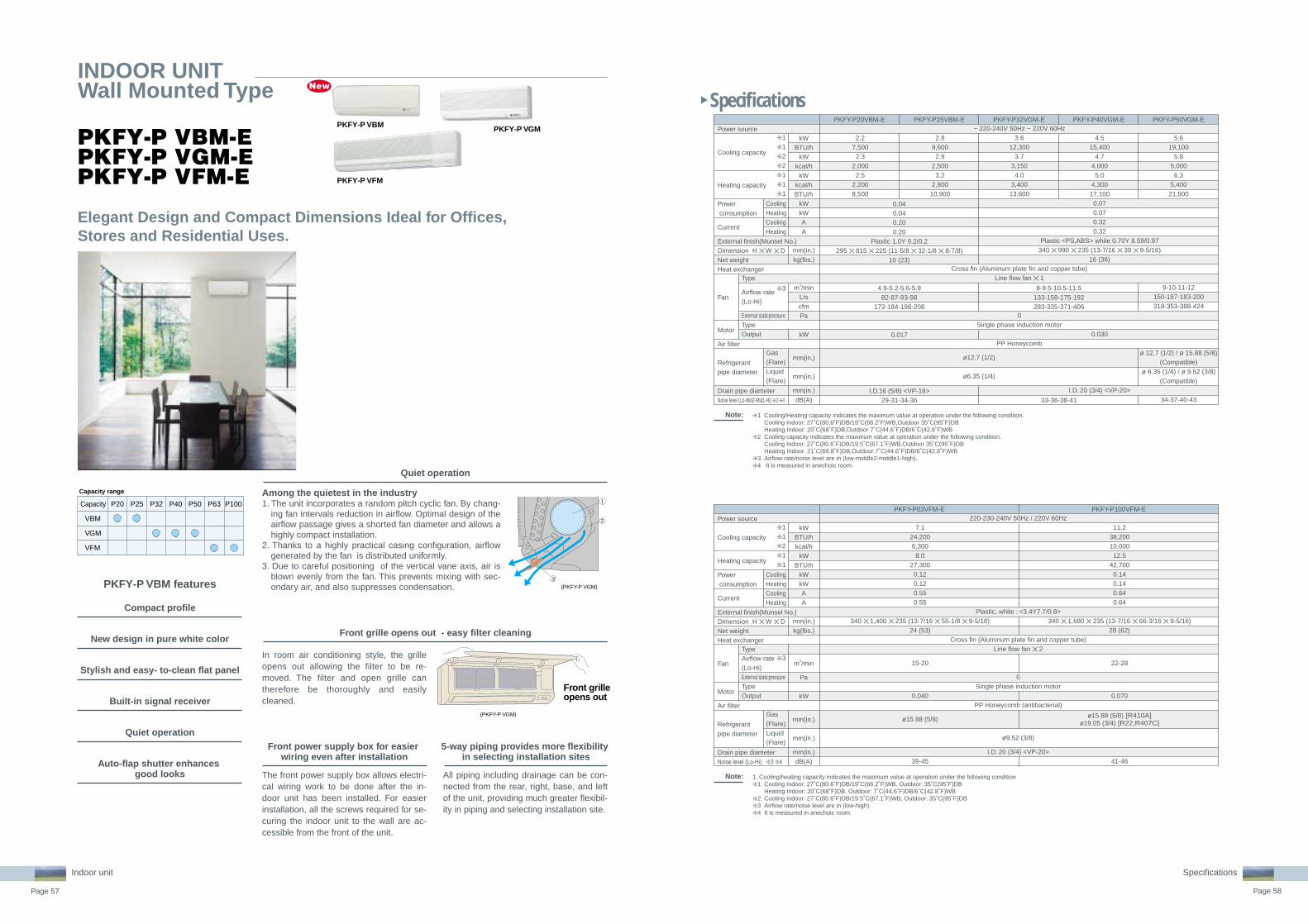
Page 57 Page 58
Specifications
Specifications
Front grille opens out
P20Capacity P25 P32 P40 P50
VBM
VGM
VFM
P63 P100
Capacity range
3
(PKFY-P VGM)
(PKFY-P VGM)
1
2
PKFY-P VBM-EPKFY-P VGM-EPKFY-P VFM-E
INDOOR UNITWall Mounted Type
Elegant Design and Compact Dimensions Ideal for Offices, Stores and Residential Uses.
PKFY-P VFM
PKFY-P VGMPKFY-P VBM
Compact profile
PKFY-P VBM features
The front power supply box allows electri-cal wiring work to be done after the in-door unit has been installed. For easier installation, all the screws required for se-curing the indoor unit to the wall are ac-cessible from the front of the unit.
Front power supply box for easier wiring even after installation
All piping including drainage can be con-nected from the rear, right, base, and left of the unit, providing much greater flexibil-ity in piping and selecting installation site.
5-way piping provides more flexibility in selecting installation sites
Auto-flap shutter enhances good looks
In room air conditioning style, the grille opens out allowing the filter to be re-moved. The filter and open grille can therefore be thoroughly and easily cleaned.
Among the quietest in the industry1. The unit incorporates a random pitch cyclic fan. By chang-
ing fan intervals reduction in airflow. Optimal design of the airflow passage gives a shorted fan diameter and allows a highly compact installation.
2. Thanks to a highly practical casing configuration, airflow generated by the fan is distributed uniformly.
3. Due to careful positioning of the vertical vane axis, air is blown evenly from the fan. This prevents mixing with sec-ondary air, and also suppresses condensation.
Quiet operation
Front grille opens out - easy filter cleaningNew design in pure white color
Stylish and easy- to-clean flat panel
Built-in signal receiver
Quiet operation
Indoor unit
Note: 1. Cooling/heating capacity indicates the maximum value at operation under the following condition❇ 1 Cooling Indoor: 27˚C(80.6˚F)DB/19˚C(66.2˚F)WB, Outdoor: 35˚C(95˚F)DB
Heating Indoor: 20˚C(68˚F)DB, Outdoor: 7˚C(44.6˚F)DB/6˚C(42.8˚F)WB❇ 2 Cooling Indoor: 27˚C(80.6˚F)DB/19.5˚C(67.1˚F)WB, Outdoor: 35˚C(95˚F)DB ❇ 3 Airflow rate/noise level are in (low-high).❇ 4 It is measured in anechoic room.
Power source
Cooling capacity
Heating capacity
Power consumption
Current
External finish(Munsel No.)Dimension H ✕ W ✕ DNet weightHeat exchanger
Fan
Motor
Air filter
Refrigerantpipe diameter
Drain pipe diameterNoise level (Lo-Hi) ❇ 3 ❇ 4
Gas(Flare)Liquid(Flare)
TypeAirflow rate(Lo-Hi)External staticpressure TypeOutput
CoolingHeatingCoolingHeating
kWBTU/hkcal/h
kWBTU/h
kWkWAA
mm(in.)kg(lbs.)
m3/min
Pa
kW
mm(in.)
mm(in.)
mm(in.)dB(A)
❇ 1❇ 1❇ 2❇ 1❇ 1
❇ 3
PKFY-P63VFM-E PKFY-P100VFM-E
7.124,2006,3008.0
27,3000.120.120.550.55
340 ✕ 1,400 ✕ 235 (13-7/16 ✕ 55-1/8 ✕ 9-5/16)24 (53)
15-20
0.040
ø15.88 (5/8)
39-45
11.238,20010,00012.5
42,7000.140.140.640.64
340 ✕ 1,680 ✕ 235 (13-7/16 ✕ 66-3/16 ✕ 9-5/16)28 (62)
22-28
0.070
41-46
220-230-240V 50Hz / 220V 60Hz
Plastic, white : <3.4Y7.7/0.8>
Cross fin (Aluminum plate fin and copper tube)Line flow fan ✕ 2
0Single phase induction motor
PP Honeycomb (antibacterial)
ø9.52 (3/8)
I.D. 20 (3/4) <VP-20>
Note: ❇ 1 Cooling/Heating capacity indicates the maximum value at operation under the following condition.Cooling Indoor: 27˚C(80.6˚F)DB/19˚C(66.2˚F)WB,Outdoor 35˚C(95˚F)DBHeating Indoor: 20˚C(68˚F)DB,Outdoor 7˚C(44.6˚F)DB/6˚C(42.8˚F)WB
❇ 2 Cooling capacity indicates the maximum value at operation under the following condition.Cooling Indoor: 27˚C(80.6˚F)DB/19.5˚C(67.1˚F)WB,Outdoor 35˚C(95˚F)DBHeating Indoor: 21˚C(69.8˚F)DB,Outdoor 7˚C(44.6˚F)DB/6˚C(42.8˚F)WB
❇ 3 Airflow rate/noise level are in (low-middle2-middle1-high).❇ 4 It is measured in anechoic room.
Power source
Cooling capacity
Heating capacity
Power consumption
Current
External finish(Munsel No.)Dimension H ✕ W ✕ DNet weightHeat exchanger
Fan
Motor
Air filter
Refrigerantpipe diameter
Drain pipe diameterNoise level (Lo-Mid2-Mid1-Hi) ❇ 3 ❇ 4
Gas(Flare)Liquid(Flare)
Type
Airflow rate(Lo-Hi)
External staticpressure TypeOutput
CoolingHeatingCoolingHeating
kWBTU/h
kWkcal/h
kWkcal/hBTU/h
kWkWAA
mm(in.)kg(lbs.)
m3/minL/scfmPa
kW
mm(in.)
mm(in.)
mm(in.)dB(A)
❇ 1❇ 1❇ 2❇ 2❇ 1❇ 1❇ 1
❇ 3
PKFY-P20VBM-E PKFY-P25VBM-E PKFY-P32VGM-E PKFY-P40VGM-E PKFY-P50VGM-E
2.27,5002.3
2,0002.5
2,2008,500
2.89,6002.9
2,5003.2
2,80010,900
4.515,400
4.74,0005.0
4,30017,1000.070.070.320.32
Plastic <PS,ABS> white 0.70Y 8.59/0.97340 ✕ 990 ✕ 235 (13-7/16 ✕ 39 ✕ 9-5/16)
16 (36)
0.030
I.D. 20 (3/4) <VP-20>
5.619,100
5.85,000
6.35,40021,500
9-10-11-12150-167-183-200318-353-388-424
ø 12.7 (1/2) / ø 15.88 (5/8)(Compatible)
ø 6.35 (1/4) / ø 9.52 (3/8)(Compatible)
34-37-40-43
~ 220-240V 50Hz ~ 220V 60Hz3.6
12,3003.7
3,1504.0
3,40013,600
Cross fin (Aluminum plate fin and copper tube)Line flow fan ✕ 1
0Single phase induction motor
PP Honeycomb
0.040.040.200.20
Plastic 1.0Y 9.2/0.2295 ✕ 815 ✕ 225 (11-5/8 ✕ 32-1/8 ✕ 8-7/8)
10 (23)
4.9-5.2-5.6-5.982-87-93-98
173-184-198-208
0.017
I.D.16 (5/8) <VP-16>29-31-34-36
ø12.7 (1/2)
ø6.35 (1/4)
8-9.5-10.5-11.5133-158-175-192283-335-371-406
33-36-38-41
New
ø15.88 (5/8) [R410A]ø19.05 (3/4) [R22,R407C]

Page 59 Page 60
Specifications
Specifications
PFFY-P VKM-E
INDOOR UNITFloor standing Type
For living rooms, bed rooms, or offices where a sophisticated design is required. The latest Mitsubishi innovation – floor-standing air-conditioner sophisticated in design, rich in function.
PFFY-P VKM-E
Indoor unit
Note:
New
Comfy room temperatures are realized by the optimum, powerful and efficient air distribution through upper and lower air outlets.The upper vane angle is remote controllable, with 5 air flow direction levels (+Swing and Auto modes) and 4 wind power levels (+Auto mode). By setting the vane angle almost vertical, annoying direct wind can be avoided for your better comfort.
Mitsubishi Electric air conditioners have always been some of the quietest model available in the market. Our new floor-standing models are no exception.It can create a silent and comfortable space where the occupants would not even recognize the existence of air conditioner operation.
From Mitsubishi Electric, an innovative new floor-standing air-conditioner. Our pleasing mix of streamlined form and diversified function. Engineered to keep room walls free, furnish comfy cooling in summer, toasty heating in winter. The “Glossy Pure White” colour ensures a deluxe look, the perfect match for any room. Both upper and lower air outlets remain closed when switched OFF, in a smart and striking image. A superb new air-conditioner from Mitsubishi, providing a handsome fit for your own distinctive interior.
The unit body is slim and trim, the essence in compact. An ideal size for living rooms, bedrooms, and more.The removable and washable front panel makes cleaning a snap.Easy and regular cleaning allows your air-conditioner stay beautiful while keeping its energy-efficient operation always possible.
ONLYONLY
27dB27dB✻ 2.5kw class
Noise level
10dB40dB60dB80dB
Subway car interior
Quiet passenger car interior (40km/h)
Library interior
Human hearing limits
(Extremely quiet)Sound of
rustling leaves
27dBthe
quietest!
Sleek louvers look just like flat panels
Smart upper/lower air outlets close when switched off
Deluxe look in “Glossy Pure White” color
700mm
60
0m
m
200mm
The air from both upper and lower air outlets is optimally controlled and distrib-uted evenly to every corner of the room. In heating mode, the warm air is smartly controlled to stay at the floor level: Your feet do not feel chilled any more! 14 16 18 20 22 24 26 ˚C
❇ 1 Cooling Indoor: 27˚C(80.6˚F)DB/19˚C(66.2˚F)WB, Outdoor: 35˚C(95˚F)DBHeating Indoor: 20˚C(68˚F)DB, Outdoor: 7˚C(44.6˚F)DB/6˚C(42.8˚F)WB
❇ 2 Airflow rate/noise level are in (Low-Mid-High-SHi).❇ 3 It is measured in anechoic room.
1. Cooling/heating capacity indicates the maximum value at operation under the following condition.
❇ 1
❇ 1
❇ 2
❇ 3❇ 2
1-phase 220-240V 50Hz
Cross fin (Alminium plate fin and copper tube)Line flow fan 5 2
0
DC motor0.03 ✕ 2
PP honeycomb fabric (Catechin Filter) 12.7 6.35
PFFY-P20VKM-E PFFY-P25VKM-EPower sourceCooling capacityHeating capacityPower consumptionCurrent
Dimension
WeightHeat exchanger
Fan
Motor
Air filterRefrigerantpipe diameterNoise level(Low-Mid-High-SHi)
kWkWkWkWAA
mmmmmmkg
m3/min
Pa
kW
mmmm
dB(A)
CoolingHeatingCoolingHeatingHeightWidthDepth
Gas(Flare)Liquid(Flare)
TypeAirflow rate(Low-Mid-High-SHi)External staticpressureTypeOutput
PFFY-P32VKM-E PFFY-P40VKM-E
2.22.5
0.0250.0250.200.2060070020015
5.9-6.8-7.6-8.7
27-31-34-37
2.83.2
0.0250.0250.200.2060070020015
6.1-7.0-8.0-9.1
28-32-35-38
3.64.0
0.0250.0250.200.2060070020015
6.1-7.0-8.0-9.1
28-32-35-38
4.55.0
0.0280.0280.240.2460070020015
8.0-9.0-9.5-10.7
35-38-42-44
Quiet operation
Optimum Air DistributionSophisticated Design
Slim but Mighty

Page 61 Page 62
Specifications
Neatly installed with pericover concealed.Easy installation in perimeter zone.
Compact unit for easy air conditioning in perimeter zone.
Electronics dry functiondehumidify refreshingly.
PFFY-P VLEM-E
PFFY-P VLRM-E
INDOOR UNITFloor standing type
INDOOR UNITFloor mounted concealed type
Standardized design with mild lines.Supports various types of spaces from office buildings and shop buildings to hospitals.Water vapor permeable film humidifier can be installed.Remote control can be installed onto the main unit.
The compact body of 220mm(8-11/16in.) in depth can be easily installed in the perimeter zone for effective air condition-ing in the perimeter zone.
Optimum dehumidification depending on indoor temperature to prevent over-cool-ing. Refreshing dehumidification can be attained.
The body is concealed in the pericover to pursue harmony with the interior.The compact body of 220mm(8-11/16in.) in depth can be easily installed in the perimeter zone.
Compact unit for easy air conditioning in perimeter zone.
Optimum dehumidification depending on indoor temperature to prevent over-cooling. Re-freshing dehumidification can be attained.
Electronics dry function dehumidify refreshingly to prevent over-cooling.
Floor mounted lowboy type effective in perimeter zone.
Indoor unit
Specifications
Note: ❇ 1 Cooling/Heating capacity indicates the maximum value at operation under the following condition.Cooling Indoor: 27˚C(80.6˚F)DB/19˚C(66.2˚F)WB,Outdoor 35˚C(95˚F)DBHeating Indoor: 20˚C(68˚F)DB,Outdoor 7˚C(44.6˚F)DB/6˚C(42.8˚F)WB
❇ 2 Cooling capacity indicates the maximum value at operation under the following condition.Cooling Indoor: 27˚C(80.6˚F)DB/19.5˚C(67.1˚F)WB,Outdoor 35˚C(95˚F)DBHeating Indoor: 21˚C(69.8˚F)DB,Outdoor 7˚C(44.6˚F)DB/6˚C(42.8˚F)WB
❇ 3 Air flow rate/noise level are in (Low-High)❇ 4 Measured point : 1m51m, Power supply : AC240V/50Hz
·1dB(A) lower at AC230V/50Hz·2dB(A) lower at AC220V/50Hz·3dB(A) lower at 1.5m51.5m point
❇ 5 It is measured in anechoic room.
Power source
Cooling capacity
Heating capacity
Power consumption
Current
External finish(Munsel No.)
Dimension H ✕ W ✕ D
Net weightHeat exchanger
Fan
Motor
Air filter
Refrigerantpipe diameter
Drain pipe diameterNoise level (Low-High) ❇ 3 ❇ 4 ❇ 5
Gas(Flare)Liquid(Flare)
Type
Airflow rate(Lo-Mid2-Mid1-Hi)
External staticpressure TypeOutput
CoolingHeatingCoolingHeating
kWBTU/h
kWkcal/h
kWkcal/hBTU/h
kWkWAA
mmin.
kg(lbs.)
m3/minL/scfmPa
kW
mm(in.)
mm(in.)
mm(in.)dB(A)
❇ 1❇ 1❇ 2❇ 2❇ 1❇ 1❇ 1
❇ 3
PFFY-P20VLEM-E
2.27,5002.3
2,0002.5
2,2008,500
ø12.7 (1/2)
ø6.35 (1/4)
0.04 / 0.060.04 / 0.060.19 / 0.250.19 / 0.25
630 ✕ 1,050 ✕ 22024-13/16 ✕ 41-3/8 ✕ 8-11/16
23 (51)
Sirocco fan ✕ 15.5-6.592-108
194-230
0.015
34-40
630 ✕ 1,410 ✕ 22024-13/16 ✕ 55-9/16 ✕ 8-11/16
PFFY-P25VLEM-E
2.89,6002.9
2,5003.2
2,80010,900
PFFY-P32VLEM-E
3.612,300
3.73,1504.0
3,40013,600
0.06 / 0.070.06 / 0.070.29 / 0.300.29 / 0.30
25 (56)
7.0-9.0117-150247-318
0.018
35-40
PFFY-P40VLEM-E
4.515,400
4.74,0005.0
4,30017,100
0.065 / 0.0750.065 / 0.0750.32 / 0.330.32 / 0.33
26 (58)
9.0-11.0150-183318-388
0.030
PFFY-P50VLEM-E
5.619,100
5.85,0006.3
5,40021,500
0.085 / 0.090.085 / 0.090.40 / 0.410.40 / 0.41
30 (67)
12.0-14.0200-233424-494
0.035
ø12.7 (1/2)
ø6.35 (1/4)
PFFY-P63VLEM-E
7.124,200
7.36,300
8.06,90027,300
0.1 / 0.110.1 / 0.110.46 / 0.470.46 / 0.47
32 (71)
12.0-15.5200-258424-547
0.063
ø15.88 (5/8)
ø9.52 (3/8)
40-46
~ 220-240V 50Hz / ~ 208-230V 60Hz
Acrylic paint (5Y 8/1)630 ✕ 1,170 ✕ 220
24-13/16 ✕ 46-1/8 ✕ 8-11/16
Cross fin (Aluminum plate fin and copper tube)
0Single phase induction motor
PP Honeycomb fabric (washable)
I.D.26 (1) <Accessary hose O.D.27 (top end :O.D.20)>
Sirocco fan ✕ 2
38-43
Power source
Cooling capacity
Heating capacity
Power consumption
Current
External finish(Munsel No.)
Dimension H ✕ W ✕ D
Net weightHeat exchanger
Fan
Motor
Air filter
Refrigerantpipe diameter
Drain pipe diameterNoise level (Low-High) ❇ 3 ❇ 4 ❇ 5
Gas(Flare)Liquid(Flare)
Type
Airflow rate(Lo-Mid2-Mid1-Hi)
External staticpressure TypeOutput
CoolingHeatingCoolingHeating
kWBTU/h
kWkcal/h
kWkcal/hBTU/h
kWkWAA
mmin.
kg(lbs.)
m3/minL/scfmPa
kW
mm(in.)
mm(in.)
mm(in.)dB(A)
❇ 1❇ 1❇ 2❇ 2❇ 1❇ 1❇ 1
❇ 3
PFFY-P20VLRM-E
2.27,5002.3
2,0002.5
2,2008,500
ø12.7 (1/2)
ø6.35 (1/4)
0.04 / 0.060.04 / 0.060.19 / 0.250.19 / 0.25
639 ✕ 886 ✕ 22025-3/16 ✕ 34-15/16 ✕ 8-11/16
18.5 (41)
Sirocco fan ✕ 15.5-6.592-108
194-230
0.015
34-40
639 ✕ 1,246 ✕ 22025-3/16 ✕ 49-1/16 ✕ 8-11/16
PFFY-P25VLRM-E
2.89,6002.9
2,5003.2
2,80010,900
PFFY-P32VLRM-E
3.612,300
3.73,1504.0
3,40013,600
0.06 / 0.070.06 / 0.070.29 / 0.300.29 / 0.30
20 (45)
7.0-9.0117-150247-318
0.018
35-40
PFFY-P40VLRM-E
4.515,400
4.74,0005.0
4,30017,100
0.065 / 0.0750.065 / 0.0750.32 / 0.330.32 / 0.33
21 (47)
9.0-11.0150-183318-388
0.030
PFFY-P50VLRM-E
5.619,100
5.85,0006.3
5,40021,500
0.085 / 0.090.085 / 0.090.40 / 0.410.40 / 0.41
25 (56)
12.0-14.0200-233424-494
0.035
ø12.7 (1/2)
ø6.35 (1/4)
PFFY-P63VLRM-E
7.124,200
7.36,300
8.06,90027,300
0.1 / 0.110.1 / 0.110.46 / 0.470.46 / 0.47
27 (60)
12.0-15.5200-258424-547
0.063
ø15.88 (5/8)
ø9.52 (3/8)
40-46
~ 220-240V 50Hz / ~ 208-230V 60Hz
Galvanizing639 ✕ 1,006 ✕ 220
25-3/16 ✕ 39-5/8 ✕ 8-11/16
Cross fin (Aluminum plate fin and copper tube)
0Single phase induction motor
PP Honeycomb fabric (washable)
I.D.26 (1) <Accessary hose O.D.27 (top end :O.D.20)>
Sirocco fan ✕ 2
38-43

Page 63 Page 64
The secret to the unmatched comfort provided by Lossnay core is the cross-flow, plate-fin structure off the heat-exchange unit. A diaphragm made of a specially processed paper fully separates inducted and exhausted air supplies, ensuring that only fresh air is introduced to the indoor environment.The superior heat-transfer and moisture permeability of the special paper assure highly effective total heat exchange (temperature and humidity) when inducted and exhausted air supplies cross in the Lossnay core.
Combine with Lossnay Ventilation System Enhanced Air Quality.Unified Control System Allows Greater Design Freedom.
Stale hot air (exhaust)
Fresh cool air(outdoor)0ûC (32ûF)
5.2ûC (41.3ûF)
20ûC (68ûF)
14.8ûC (58.6ûF)Fresh warm air (indoor supply air)
Stale warm air (indoor air)
Heat-Exchange Efficiency Obtainable Only with Lossnay.
LGH-15RX4 [150m3/h Single phase 220-240V 50Hz/60Hz]
LGH-25RX4 [250m3/h Single phase 220-240V 50Hz/60Hz]
LGH-35RX4 [350m3/h Single phase 220-240V 50Hz/60Hz]
LGH-50RX4 [500m3/h Single phase 220-240V 50Hz/60Hz]
LGH-80RX4 [800m3/h Single phase 220-240V 50Hz/60Hz]
LGH-100RX4 [1000m3/h Single phase 220-240V 50Hz/60Hz]
LGH-150RX4 [1500m3/h Single phase 220-240V 50Hz/60Hz]
LGH-200RX4 [2000m3/h Single phase 220-240V 50Hz/60Hz]
The Ventilation System for Enhanced Air Quality - Lossnay
LOSSNAYIndoor unit
• Two paths ventilation LOSSNAY simultaneously intakes Fresh Air and exhausts Dirty Air.
• Total energy recoverLOSSNAY returns BOTH sensible heat and latent heat.
LOSSNAY Technology
Mitsubishi developed “ HYPER CORE “ of World No.1
LOSSNAY recovers energy but does NOT return dirty air to indoor by Non porous paper.
• Hyper Performance [HYPER CORE]
Spacer plate
Partition plate
Fresh air induction(fresh air)
Fresh air exhaust(fresh heating/cooling air)
Stale air exhaust(dirty indoor air)
Stale air induction(dirty heating/cooling air)
Sensible heat Latent heat
IndoorsOutdoorsEA SA
RAOA
25µm
A. Two paths ventilation
No dirty air return Mitsubishi has World No.1 Energy exchange efficiency.
High Performance
B. Total Energy transfer
Water moleculeGas (CO2) molecule
Exhaust airflow
Supply airflow Non-porous ultra-thin filmmaterial: 25µm
64.5
70%
60%
15RX4
Ent
halp
y ex
chan
ge e
ffici
ency
(fo
r co
olin
g)
25RX4 35RX4 50RX4 65RX4 80RX4 100RX4 150RX4 200RX4
62.5 62.5
61.5
64.5 64.5 64.5 64.565.5
65
6867 67 67
68
64.5 64.5
UPby 3 to 4
point
Conventional models
RX4

Page 65 Page 66
ADVANTAGESClean air supply, dirty air exhaust by Two air paths (OA SA and RA EA)Energy recovery by LOSSNAY CoreFree cooling by bypass damperMULTI VENTILATION MODE for multi ventilation request (Power supply, Power supply/exhaust, Power exhaust)
• Without ventilation...Lack of Ventilation makes people sick by dirty indoor air including CO2, Dust, Bacteria.
• If just opening windows...Opening windows eliminates dirty air BUT wastes much air-con energy.
• So we recommend LOSSNAY LOSSNAY is simultaneous pursuit of Ventilation and Energy Saving.
EA (exhaust air)
OA (outside air)
SA (supply air)
RA (returt air)
RX4 SERIES
• This is LOSSNAY !
Why LOSSNAY is necessary.
Ventilation Energy Save
UNIT STRUCTURE
LOSSNAY Core
Energy Recovery Image
Bypass damper
How much recovery?OA temp. : 0˚C SA temp. : 15.4˚C
(Indoor 20˚C)
15.4˚CThermal energy
Outdoor:0˚C Indoor:20˚C
Air conditioner
Indoor unit
Multi Ventilation Mode to control air volume balance
All LGH models feature the "Multi-ventilation Mode," which allows the air supply/exhaust balance to be varied dynami-cally to suit the usage environment and location. Modes can be selected easily by setting the connectors on the circuit board.
Easy InstallationFlexible duct work is available.
Normal office,etc.
Smaller offices or tenant buildings,etc.
Smoking areas,etc.
Many people in an office Extractor fan working place Priority air exhaust
Power air supply/exhaust Power air supply Power air exhaust
EA OAEA OA
A space is necessary to prevent the influx of rainwater.
Can be installed close to the surface of the wall.
Standard installation Installation
Changing the duct direction
ExchangeableAperture Plate
Collar
LOSSNAY features
* "High" can be further set to "Extra high" using the dip switch.
Ventilation Mode
Power air supply/exhaust mode
Power air supply mode
Power air exhaust mode
Energy-saving ventilation mode
Supply
Airflow
High
High
Low
Low
Exhaust
Airflow
High
Low
High
Low
LOSSNAY

Page 67 Page 68
Appearance
Model line up
Installation
Specification
M-NET system with City MultiFlexible system, for your multi demand
LOSSNAY ventilation combined with Air-con
LGH-50RX4-E LGH-200RX4-E
Model
Power source
Size L mm
W mm
H mm
Volume m3
Weight kg
Duct diameter [mm]
Air Volume Shi CMH
Static Pressure Shi Pa
Sound level A Shi dB
Sound level B Shi dB
Ex. Effciency Temp. %
Heatin %
Cooling %
15R 25R 35R 50R 65R 80R 100R 150R 200R
200/240V 1Ph 50/60Hz
780 780 888 1016 954 1164 1263 1413 1413
610 735 874 888 908 1004 1164 1004 1231
275 275 317 317 388 398 398 800 800
0.13 0.16 0.25 0.29 0.34 0.47 0.59 1.13 1.39
17 21 30 33 46 61 69 138 161
100 150 150 200 250 250 250 350 350
150 250 350 500 650 800 1000 1500 2000
95 80 150 150 110 140 160 140 150
26 26.5 31 33 34.5 33.5 36 36.5 39
33 34.5 39 41 42.5 44.5 47 49 51.5
77 78 79 77 77 78 79 79 79
70 70 70 67.5 67.5 71 71 72 71
65.5 65 68 64.5 64.5 67 67 68 67
Model: LGH-RX4 series
Power supply unit
Centralized controller Outdoor unit
PAR-F27MEA PAR-F27MEA
Indoor unit Indoor unit
UP
Indoor unit LOSSNAY
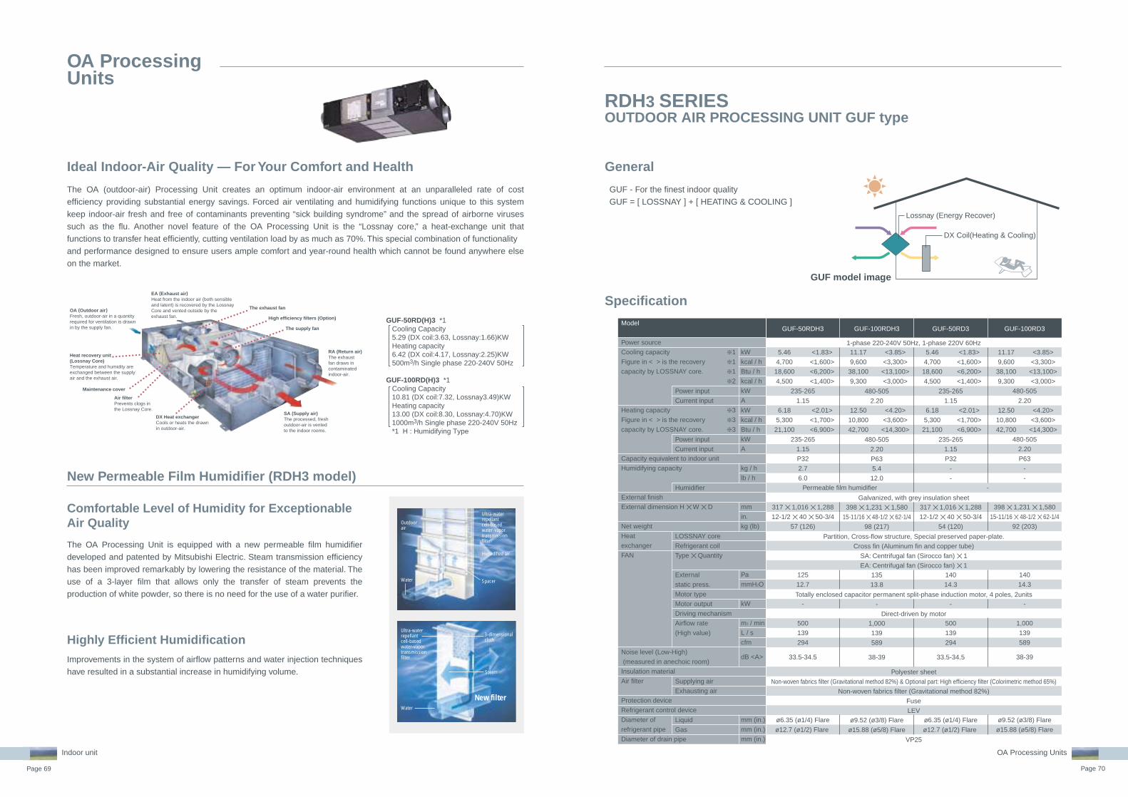
Page 69 Page 70
GUF - For the finest indoor qualityGUF = [ LOSSNAY ] + [ HEATING & COOLING ]
RDH3 SERIESOUTDOOR AIR PROCESSING UNIT GUF type
General
Specification
Lossnay (Energy Recover)
DX Coil(Heating & Cooling)
GUF model image
Indoor unit
The OA Processing Unit is equipped with a new permeable film humidifier developed and patented by Mitsubishi Electric. Steam transmission efficiency has been improved remarkably by lowering the resistance of the material. The use of a 3-layer film that allows only the transfer of steam prevents the production of white powder, so there is no need for the use of a water purifier.
The OA (outdoor-air) Processing Unit creates an optimum indoor-air environment at an unparalleled rate of cost efficiency providing substantial energy savings. Forced air ventilating and humidifying functions unique to this system keep indoor-air fresh and free of contaminants preventing “sick building syndrome” and the spread of airborne viruses such as the flu. Another novel feature of the OA Processing Unit is the “Lossnay core,” a heat-exchange unit that functions to transfer heat efficiently, cutting ventilation load by as much as 70%. This special combination of functionality and performance designed to ensure users ample comfort and year-round health which cannot be found anywhere else on the market.
GUF-50RD(H)3 *1 Cooling Capacity 5.29 (DX coil:3.63, Lossnay:1.66)KW Heating capacity 6.42 (DX coil:4.17, Lossnay:2.25)KW 500m3/h Single phase 220-240V 50Hz
GUF-100RD(H)3 *1 Cooling Capacity 10.81 (DX coil:7.32, Lossnay3.49)KW Heating capacity 13.00 (DX coil:8.30, Lossnay:4.70)KW 1000m3/h Single phase 220-240V 50Hz *1 H : Humidifying Type
New Permeable Film Humidifier (RDH3 model)
Outdoor air
Ultra-water repellant cell-based water-vapor transmission filter
Water
Ultra-water repellant cell-based water-vapor transmission filter
Water
Steam
New filter
3-dimensional cloth
Spacer
Humidified air
OA ProcessingUnits
Air filterPrevents clogs in the Lossnay Core.
DX Heat exchangerCools or heats the drawn in outdoor-air.
SA (Supply air)The processed, fresh outdoor-air is vented to the indoor rooms.
RA (Return air)The exhaust fan draws in contaminated indoor-air.
EA (Exhaust air)Heat from the indoor air (both sensible and latent) is recovered by the Lossnay Core and vented outside by the exhaust fan.
The exhaust fan
High efficiency filters (Option)
The supply fan
Maintenance cover
OA (Outdoor air)Fresh, outdoor-air in a quantity required for ventilation is drawn in by the supply fan.
Heat recovery unit(Lossnay Core)Temperature and humidity are exchanged between the supply air and the exhaust air.
Comfortable Level of Humidity for Exceptionable Air Quality
Improvements in the system of airflow patterns and water injection techniques have resulted in a substantial increase in humidifying volume.
Highly Efficient Humidification
Ideal Indoor-Air Quality — For Your Comfort and Health
Model
Power source
Cooling capacity
Figure in < > is the recovery
capacity by LOSSNAY core.
Heating capacity
Figure in < > is the recovery
capacity by LOSSNAY core.
Capacity equivalent to indoor unit
Humidifying capacity
External finish
External dimension H ✕ W ✕ D
Net weight
Heat
exchanger
FAN
Noise level (Low-High)
(measured in anechoic room)
Insulation material
Air filter
Protection device
Refrigerant control device
Diameter of
refrigerant pipe
Diameter of drain pipe
kW
kcal / h
Btu / h
kcal / h
kW
A
kW
kcal / h
Btu / h
kW
A
kg / h
lb / h
mm
in.
kg (lb)
Pa
mmH2O
kW
m3 / min
L / s
cfm
dB <A>
mm (in.)
mm (in.)
mm (in.)
❇ 1
❇ 1
❇ 1
❇ 2
❇ 3
❇ 3
❇ 3
Power input
Current input
Power input
Current input
Humidifier
LOSSNAY core
Refrigerant coil
Type ✕ Quantity
External
static press.
Motor type
Motor output
Driving mechanism
Airflow rate
(High value)
Supplying air
Exhausting air
Liquid
Gas
GUF-50RDH3 GUF-100RDH3 GUF-50RD3 GUF-100RD3
235-265
1.15
235-265
1.15
P32
2.7
6.0
317 ✕ 1,016 ✕ 1,288
12-1/2 ✕ 40 ✕ 50-3/4
57 (126)
125
12.7
-
500
139
294
33.5-34.5
ø6.35 (ø1/4) Flare
ø12.7 (ø1/2) Flare
480-505
2.20
480-505
2.20
P63
5.4
12.0
398 ✕ 1,231 ✕ 1,580
15-11/16 ✕ 48-1/2 ✕ 62-1/4
98 (217)
135
13.8
-
1,000
139
589
38-39
ø9.52 (ø3/8) Flare
ø15.88 (ø5/8) Flare
235-265
1.15
235-265
1.15
P32
-
-
317 ✕ 1,016 ✕ 1,288
12-1/2 ✕ 40 ✕ 50-3/4
54 (120)
140
14.3
-
500
139
294
33.5-34.5
ø6.35 (ø1/4) Flare
ø12.7 (ø1/2) Flare
480-505
2.20
480-505
2.20
P63
-
-
398 ✕ 1,231 ✕ 1,580
15-11/16 ✕ 48-1/2 ✕ 62-1/4
92 (203)
140
14.3
-
1,000
139
589
38-39
ø9.52 (ø3/8) Flare
ø15.88 (ø5/8) Flare
1-phase 220-240V 50Hz, 1-phase 220V 60Hz
Galvanized, with grey insulation sheet
Partition, Cross-flow structure, Special preserved paper-plate.
Cross fin (Aluminum fin and copper tube)
SA: Centrifugal fan (Sirocco fan) ✕ 1
EA: Centrifugal fan (Sirocco fan) ✕ 1
Totally enclosed capacitor permanent split-phase induction motor, 4 poles, 2units
Direct-driven by motor
Polyester sheet
Non-woven fabrics filter (Gravitational method 82%) & Optional part: High efficiency filter (Colorimetric method 65%)
Non-woven fabrics filter (Gravitational method 82%)
Fuse
LEV
VP25
Permeable film humidifier -
<1.83>
<1,600>
<6,200>
<1,400>
<2.01>
<1,700>
<6,900>
5.46
4,700
18,600
4,500
6.18
5,300
21,100
11.17
9,600
38,100
9,300
12.50
10,800
42,700
<3.85>
<3,300>
<13,100>
<3,000>
<4.20>
<3,600>
<14,300>
<1.83>
<1,600>
<6,200>
<1,400>
<2.01>
<1,700>
<6,900>
5.46
4,700
18,600
4,500
6.18
5,300
21,100
<3.85>
<3,300>
<13,100>
<3,000>
<4.20>
<3,600>
<14,300>
11.17
9,600
38,100
9,300
12.50
10,800
42,700
OA Processing Units

Page 72
O utdoor unit
Heat Pump Series
Heat Pump Series - High COP
Water Cooled Series
Page 71
Indoor unit

Page 74Page 73
Outdoor unit Outdoor unit
WY (Heat Pump) Series (8,10,16,20HP)
PQHY-P YGM-A
Heat Pump Series - High COP
Page91
Water Cooled Series
Y Series - High COP (8HP/12HP)
PUHY-EP YHM-A
Page85
Model
Model Name
8HP
PUHY-EP200YHM-A(-BS)
12HP
PUHY-EP300YHM-A(-BS)
S Series (4HP-6HP)
Y Series (20HP-26HP)
Y Series (8HP-12HP)
Y Series (14HP-18HP)
Y Series (28HP-36HP)
Y Series (38HP)
Y Series (40HP-42HP)
PUHY-P YSHM-A
PUHY-P YSHM-A
PUHY-P YSHM-A
Wide selection of outdoor units Wide selection of outdoor units
Heat Pump Series
PUMY-P VHMPUMY-P YHM
PUHY-P YSHM-A
PUHY-P YHM-A
PUHY-P YHM-A
PUHY-P YSHM-A
Y Series (44HP-50HP)
Page75,76 Page80,81
Page77 Page82
Page78 Page82
Page79 Page83,84
Model
Model Name
4HP
PUMY-P100VHM
PUMY-P100YHM
5HP
PUMY-P125VHM
PUMY-P125YHM
6HP
PUMY-P140VHM
PUMY-P140YHM
Model
Model Name
8HP
PUHY-P200YHM-A
10HP
PUHY-P250YHM-A
12HP
PUHY-P300YHM-A
Model
Model Name
16HP
PUHY-P400YHM-A
18HP
PUHY-P450YHM-A
Model
Model Name
38HP
PUHY-P950YSHM-A
Model
Model Name
46HP
PUHY-P1150YSHM-A
50HP
PUHY-P1250YSHM-A
44HP
PUHY-P1100YSHM-A
48HP
PUHY-P1200YSHM-A
Model
Model Name
22HP
PUHY-P550YSHM-A
26HP
PUHY-P650YSHM-A
20HP
PUHY-P500YSHM-A
24HP
PUHY-P600YSHM-A
Model
Model Name
10HP
PQHY-P250YGM-A
20HP
PQHY-P500YSGM-A
8HP
PQHY-P200YGM-A
16HP
PQHY-P400YSGM-A
Model
Model Name
40HP
PUHY-P1000YSHM-A
42HP
PUHY-P1050YSHM-A
❇ The PUHY-P-YSHM-A series requires a Twinning kit (optional). Refer to the data book for details. ❇ The PUHY-P-YSHM-A series requires a Twinning kit (optional). Refer to the data book for details. ❇ Unit photos are all standard models.
14HP
PUHY-P350YHM-A
Model
Model Name
28HP
PUHY-P700YSHM-A
30HP
PUHY-P750YSHM-A
34HP
PUHY-P850YSHM-A
36HP
PUHY-P900YSHM-A
32HP
PUHY-P800YSHM-A
Y Series - High COP (32HP-34HP)
Y Series - High COP (36HP)
PUHY-EP YSHM-A
PUHY-EP YSHM-A
Page89
Page90
Model
Model Name
36HP
PUHY-EP900YSHM-A(-BS)
Y Series - High COP (16HP-20HP)
Y Series - High COP (22HP-26HP)
PUHY-EP YSHM-A
PUHY-EP YSHM-A
Page86
Page87
Model
Model Name
16HP
PUHY-EP400YSHM-A(-BS)
18HP
PUHY-EP450YSHM-A(-BS)
20HP
PUHY-EP500YSHM-A(-BS)
Model
Model Name
24HP
PUHY-EP600YSHM-A(-BS)
26HP
PUHY-EP650YSHM-A(-BS)
22HP
PUHY-EP550YSHM-A(-BS)
Y Series - High COP (28HP-30HP)
PUHY-EP YSHM-A
Page88
Model
Model Name
28HP
PUHY-EP700YSHM-A(-BS)
30HP
PUHY-EP750YSHM-A(-BS)
Model
Model Name
32HP
PUHY-EP800YSHM-A(-BS)
34HP
PUHY-EP850YSHM-A(-BS)

Page 75 Page 76
Outdoor unit
PUMY-P VHM
OUTDOOR UNITS Series
PUMY-P YHM
OUTDOOR UNITS Series
SpecificationsSpecifications
Power sourceCooling capacity (Nominal)
Temp. range of coolingHeating capacity(Nominal)
Temp. range of heatingIndoor unitconnectableNoise level (measured in anechoic room)Diameter of refrigerant pipeExternal finishExternal dimension H ✕ W ✕ DNet weightHeat exchanger
Compressor
FAN
Protection
Refrigerant
Power inputCurrent inputCOP (kW/kW)Indoor Outdoor
Power inputCurrent inputCOP (kW/kW) Indoor temp. Outdoor temp.
Total capacityModel/Quantity
Liquid (High press.)Gas (Low press.)
TypeStarting methodMotor output
Air flow rate
Type ✕ QuantityMotor outputHigh pressure protectionInverter circuit (COMP./FAN)CompressorType ✕ Original charge
PUMY-P100VHM PUMY-P125VHM PUMY-P140VHM
kWkcal/hBtu/hkWA
W.B.D.B.
kWkcal/hBtu/hkWA
D.B.W.B.
dB<A>mm(in.)mm(in.)
mm (in.)kg (lb)
kWm3/min
L/scfm
kW
❇ 1❇ 1❇ 1
❇ 2❇ 2❇ 2
Note:
❇ 1 Nominal cooling conditionsIndoor 27˚C (81˚F) DB/19˚C (66˚F) WB, Outdoor 35˚C (95˚F) DBPipe length 7.5 m (24-9/16 ft), Level difference 0 m (0 ft)
❇ 2 Nominal heating conditionsIndoor 20˚C (68˚F) DB,Outdoor 7˚C (45˚F) DB/6˚C (43˚F) WBPipe length 7.5 m (24-9/16 ft), Level difference 0 m (0 ft)
Note:
❇ 1 Nominal cooling conditionsIndoor 27˚CDB/19˚CWB (81˚FDB/66˚FWB), Outdoor 35˚CDB (95˚FDB)Pipe length 7.5m (24-9/16ft), Level difference 0m (0ft)
❇ 2 Nominal cooling conditionsIndoor 27˚CDB/19.5˚CWB (81˚FDB/67˚FWB) ,Outdoor 35˚CDB (95˚FDB)Pipe length 5m (16-3/8ft), Level difference 0 m (0 ft)
❇ 3 Nominal heating conditionsIndoor 20˚CDB (68˚FDB),Outdoor 7˚CDB/6˚CWBPipe length 7.5m (24-9/16ft), Level difference 0 m (0 ft)
Outdoor unit
11.29,60038,2003.34
15.4-14.8-14.1, 15.43.35
12.510,80042,7003.66
16.9-16.2-15.5, 16.93.42
P20 ~ P125 / 1 ~ 649 / 51
ø9.52 (ø3/8) Liquidø15.88 (ø5/8) Gas
1,350 ✕ 950 ✕ 330 (53-3/16 ✕ 37-7/16 ✕ 13)127 (280 lb)
2.210016673532
Propeller fan ✕ 20.06 ✕ 2
R410A ✕ 8.5kg (19 lb)
14.012,00047,8004.32
20.0-19.1-18.3, 20.03.24
16.013,80054,6004.33
20.0-19.1-18.3, 20.03.69
P20 ~ P140 / 1 ~ 850 / 52
ø9.52 (ø3/8) Liquidø15.88 (ø5/8) Gas
1,350 ✕ 950 ✕ 330 (53-3/16 ✕ 37-7/16 ✕ 13)127 (280 lb)
2.910016673532
Propeller fan ✕ 20.06 ✕ 2
R410A ✕ 8.5kg (19 lb)
15.513,30052,9005.35
24.7-23.6-22.7, 24.72.9
18.015,50061,4005.58
25.8-24.7-23.6, 25.83.23
P20 ~ P140 / 1 ~ 851 / 53
ø9.52 (ø3/8) Liquid ø15.88 (ø5/8) Gas
1,350 ✕ 950 ✕ 330 (53-3/16 ✕ 37-7/16 ✕ 13)127 (280 lb)
3.310016673532
Propeller fan ✕ 20.06 ✕ 2
R410A ✕ 8.5kg (19 lb)
1-phase 220-230-240V 50Hz, 1-phase 220V 60Hz
15 ~ 24˚C (59 ~ 75˚F)- 5 ~ 46˚C (23 ~ 115˚F)
10 to 46˚CD.B. (50 to 115˚FD.B.) : in case of connecting PKFY-P20 / P25 type indoor unit.
15 ~ 27˚C (59 ~ 81˚F)-15 ~ 15˚C (5 ~ 59˚F)
50 ~ 130% of outdoor unit capacity
Galvanized steel sheet <MUNSELL 3Y 7.8/1.1>
Salt-resistant cross fin & copper tubeInverter scroll hermetic comp.
Inverter
High pressure sensor, High pressure switch 4.15 MPaOver-heat protection, Over-current protection
Discharge thermo protection, Over-current protection
Power sourceCooling capacity (Nominal)
Temp. range of coolingHeating capacity(Nominal)
Temp. range of heatingIndoor unitconnectableNoise level (measured in anechoic room)Diameter of refrigerant pipeExternal finishExternal dimension H ✕ W ✕ DNet weightHeat exchanger
Compressor
FAN
HIC circuit (HIC: Heat Inter-Changer)
Protection
Defrosting methodRefrigerant
Power inputCurrent inputCOPIndoor Outdoor
Power inputCurrent inputCOP (kW/kW) Indoor temp. Outdoor temp.
Total capacityModel/Quantity
LiquidGas
TypeMakerStarting methodMotor outputCase heaterLubricant 5 original chargeAir flow rateExternal static press.Type ✕ QuantityControl, Driving mechanismMotor output
High pressure protectionInverter circuit (COMP./FAN)CompressorFan motor
Type ✕ Original chargeControl
PUMY-P100YHM PUMY-P125YHM PUMY-P140YHM
kWkcal/hBtu/hkcal/h
kWA
W.B.D.B.
kWkcal/hBtu/hkWA
D.B.W.B.
dB<A>mm(in.)mm(in.)
mmkg
kWkW
m3/min
kW
❇ 1❇ 1❇ 1❇ 2
❇ 3❇ 3❇ 3
11.29,600
38,200-
3.305.28-5.02-4.84
3.39
12.510,80042,7003.63
5.81-5.52-5.323.44
P20 ~ P125 / 1 ~ 649/51
1.9-
15.513,30052,90014,000
5.328.51-8.09-7.80
2.91
18.015,50061,400
5.328.51-8.09-7.80
3.38
P20 ~ P140 / 1 ~ 851/53
2.9-
3-phase, 380-400-415V, 50Hz
15 ~ 24˚C (59~75˚F)- 5 ~ 46˚C (23~115˚F)
10 to 46˚C D.B.(50 to 115˚FD.B.) : in case of connecting PKFY-P20/P25 type indoor unit.
15~27˚C (59~81˚F)-12~15˚C (10~59˚F)
50 ~ 130% of outdoor unit capacity
ø9.52 (ø3/8" ) Flare ø15.88 (ø5/38" ) Flare
Galvanized steel sheet<MUNSELL 3Y 7.8/1.1>1,350 ✕ 950 ✕ 330
140Salt-resistant cross fin & copper tubeInverter scroll hermetic compressor
Mitsubishi Electric CorporationInverter
MEL56 x 2.3 L1000 Pa
Propeller fan ✕ 2DC-control, Direct-driven by motor
0.06 x 2-
High pressure sensor, High pressure switch 4.15 MPaOver-heat protection, Over-current protection
Discharge thermo protection, Over-current protectionOver-heat protection, Voltage protection
Auto-defrost mode (Reversed refrigerant circle) R410A ✕ 8.5kg ( 19 lb)
LEV circuit
14.012,00047,80012,5004.27
6.83-6.49-6.263.28
16.013,80054,6004.29
6.87-6.52-6.293.73
P20 ~ P140 / 1 ~ 850/52
2.4-

Page 77 Page 78
Outdoor unit
PUHY-P YHM-A
OUTDOOR UNITY Series
Specifications
Outdoor unit
Power sourceCooling capacity (Nominal)
Temp. range of coolingHeating capacity(Nominal)
Temp. range of heatingIndoor unitconnectableNoise level (measured in anechoic room)Diameter of refrigerant pipeExternal finish
External dimension H ✕ W ✕ D
Net weightHeat exchangerCompressor
FAN
Protection
Refrigerant
45.038,700
153,50013.23
22.3-21.2-20.43.40
50.043,000
170,60013.47
22.7-21.6-20.83.71
P15~P250 / 1~3461
ø12.7 (ø1/2) Brazedø28.58 (ø1-1/8) Brazed
1.710(without legs 1.650) ✕ 1220 ✕ 760(67-3/8(without legs 65) ✕ 48-1/16 ✕ 29-15/16)
245 (541)
10.5225
3,7507,945
Propeller fan ✕ 10.46 ✕ 1
R410A ✕ 11.5kg (26 lb)
50.043,000170,600
16.2827.4-26.1-25.1
3.07
56.048,200191,100
15.3825.9-24.6-23.7
3.64
P15~P250 / 1~3962
ø15.88 (ø5/8) Brazedø28.58 (ø1-1/8) Brazed
1.710(without legs 1.650) ✕ 1220 ✕ 760(67-3/8(without legs 65) ✕ 48-1/16 ✕ 29-15/16)
245 (541)
12.0225
3,7507,945
Propeller fan ✕ 10.46 ✕ 1
R410A ✕ 11.5kg (26 lb)
Power inputCurrent inputCOP (kW/kW)Indoor Outdoor
Power inputCurrent inputCOP (kW/kW) Indoor temp. Outdoor temp.
Total capacityModel/Quantity
LiquidGas
TypeStarting methodMotor outputAir flow rate
Type ✕ QuantityMotor outputHigh pressure protectionInverter circuit (COMP./FAN)CompressorType ✕ Original charge
kWkcal/hBtu/hkWA
W.B.D.B.
kWkcal/hBtu/hkWA
D.B.W.B.
dB<A>mm(in.)mm(in.)
mm(in.)
kg(lb)
kWm3/min
L/scfm
kW
❇ 1❇ 1❇ 1
❇ 2❇ 2❇ 2
PUHY-P400YHM-A(-BS) PUHY-P450YHM-A(-BS)
Note:
❇ 1 Nominal cooling conditionsIndoor 27˚C (81˚F) DB/19˚C (66˚F) WB, Outdoor 35˚C (95˚F) DBPipe length 7.5 m (24-9/16 ft), Level difference 0 m (0 ft)
❇ 2 Nominal heating conditionsIndoor 20˚C (68˚F) DB,Outdoor 7˚C (45˚F) DB/6˚C (43˚F) WBPipe length 7.5 m (24-9/16 ft), Level difference 0 m (0 ft)
15~24˚C (59~75˚F)- 5~43˚C (23~109˚F)
15~27˚C (59~81˚F)-20~15.5˚C (-4~60˚F)
50~130% of outdoor unit capacity
Pre-coated galvanized steel sheets (+ powder coating for-BS type) <MUNSELL 5Y 8/1 or similar>
Salt-resistant cross fin & copper tubeInverter scroll hermetic compressor
Inverter
High pressure sensor, High pressure switch 4.15 MPa (601 psi)Over-current protection, Over-heat protection
Over-heat protection
3-phase 4-wire 380-400-415V 50/60Hz
PUHY-P YHM-A
OUTDOOR UNITY Series
Specifications
Power sourceCooling capacity (Nominal)
Temp. range of coolingHeating capacity(Nominal)
Temp. range of heatingIndoor unitconnectableNoise level (measured in anechoic room)Diameter of refrigerant pipe
External finish
External dimension H ✕ W ✕ D
Net weightHeat exchanger
Compressor
FAN
Protection
Refrigerant
Power inputCurrent inputCOP (kW/kW)Indoor Outdoor
Power inputCurrent inputCOP (kW/kW) Indoor temp. Outdoor temp.
Total capacityModel/Quantity
Liquid
Gas
TypeStarting methodMotor outputAir flow rate
Type ✕ QuantityMotor outputHigh pressure protectionInverter circuit (COMP. / FAN)CompressorType ✕ Original charge
kWkcal/hBtu/hkWA
W.B.D.B.
kWkcal/hBtu/hkWA
D.B.W.B.
dB<A>mm(in.)
mm(in.)
mm(in.)
kg(lb)
kWm3/min
L/scfm
kW
❇ 1❇ 1❇ 1
❇ 2❇ 2❇ 2
PUHY-P200YHM-A(-BS) PUHY-P250YHM-A(-BS) PUHY-P300YHM-A(-BS) PUHY-P350YHM-A(-BS)
22.419,30076,4005.72
9.6-9.1-8.83.91
25.021,50085,3006.03
10.1-9.6-9.34.14
P15~P250 / 1~1756
ø9.52 (ø3/8) Brazed
ø19.05 (ø3/4) Brazed
1,710(without legs 1,650) ✕ 920 ✕ 760(67-3/8(without legs 65) ✕ 36-1/4 ✕ 29-15/16)
185 (408)
5.4185
3,0836,532
Propeller fan ✕ 10.46 ✕ 1
R410A ✕ 6.5kg (15 lb)
28.024,10095,5007.73
13.0-12.3-11.93.62
31.527,100107,500
7.8313.2-12.5-12.1
4.02
P15~P250 / 1~2157
ø9.52 (ø3/8) Brazed(ø12.7 (ø1/2) Brazed , total length >=90m)
ø22.2 (ø7/8) Brazed
1,710(without legs 1,650) ✕ 920 ✕ 760(67-3/8(without legs 65) ✕ 36-1/4 ✕ 29-15/16)
200 (441)
6.7185
3,0836,532
Propeller fan ✕ 10.46 ✕ 1
R410A ✕ 9.0kg (20 lb)
33.528,800114,300
9.0715.3-14.5-14.0
3.69
37.532,300128,000
9.3915.8-15.0-14.5
3.99
P15~P250 / 1~2659
ø9.52 (ø3/8) Brazed(ø12.7 (ø1/2) Brazed , total length>=40m)
ø22.2 (ø7/8) Brazed
1,710(without legs 1,650) ✕ 920 ✕ 760(67-3/8(without legs 65) ✕ 36-1/4 ✕ 29-15/16)
215 (474)
8.2185
3,0836,532
Propeller fan ✕ 10.46 ✕ 1
R410A ✕ 9.0kg (20 lb)
40.034,400
136,50011.20
18.9-17.9-17.33.57
45.038,700
153,50012.09
20.4-19.3-18.63.72
P15~P250 / 1~3060
ø12.7 (ø1/2) Brazedø28.58 (ø1-1/8) Brazed
1.710(without legs 1.650) ✕ 1220 ✕ 760(67-3/8(without legs 65) ✕ 48-1/16 ✕ 29-15/16)
245 (541)
10.3225
3,7507,945
Propeller fan ✕ 10.46 ✕ 1
R410A ✕ 11.5kg (26 lb)
3-phase 4-wire 380-400-415V 50/60Hz
15~24˚C(59~75˚F)- 5~43˚C(23~109˚F)
15~27˚C(59~81˚F)-20~15.5˚C(-4~60˚F)
50~130% of outdoor unit capacity
Salt-resistant cross fin & copper tubeInverter scroll hermetic compressor
Inverter
Pre-coated galvanized steel sheets (+ powder coating for-BS type) <MUNSELL 5Y 8/1 or similar>
High pressure sensor, High pressure switch 4.15 MPa (601 psi)Over-current protection, Over-heat protection
Over-heat protection
Note:
❇ 1 Nominal cooling conditionsIndoor 27˚C (81˚F) DB/19˚C (66˚F) WB, Outdoor 35˚C (95˚F) DBPipe length 7.5 m (24-9/16 ft), Level difference 0 m (0 ft)
❇ 2 Nominal heating conditionsIndoor 20˚C (68˚F) DB,Outdoor 7˚C (45˚F) DB/6˚C (43˚F) WBPipe length 7.5 m (24-9/16 ft), Level difference 0 m (0 ft)

Page 79 Page 80
Outdoor unit
PUHY-P YSHM-A
OUTDOOR UNITY Series
Specifications
Outdoor unit
PUHY-P YSHM-A
OUTDOOR UNITY Series
Specifications
Note:
❇ 1 Nominal cooling conditionsIndoor 27˚C (81˚F) DB/19˚C (66˚F) WB, Outdoor 35˚C (95˚F) DBPipe length 7.5 m (24-9/16 ft), Level difference 0 m (0 ft)
❇ 2 Nominal heating conditionsIndoor 20˚C (68˚F) DB,Outdoor 7˚C (45˚F) DB/6˚C (43˚F) WBPipe length 7.5 m (24-9/16 ft), Level difference 0 m (0 ft)
❇ 3 Height without legs 1650mm(65 in.)
Set namePower sourceCooling capacity (Nominal)
Temp. range of coolingHeating capacity(Nominal )
Temp. range of heatingIndoor unitconnectableNoise level (measured in anechoic room)Diameter of refrigerant pipeOutdoor unit 1 and Outdoor unit 2
External finish
External dimension H ✕ W ✕ D
Net weightHeat exchangerCompressor
FAN
Protection
Refrigerant
Twinning kit (optional)
Power inputCurrent inputCOP (kW / kW)Indoor Outdoor
Power inputCurrent inputCOP (kW/kW) Indoor temp. Outdoor temp.
Total capacityModel/Quantity
LiquidGas
TypeStarting methodMotor outputAir flow rate
Type ✕ QuantityMotor outputHigh pressure protectionInverter circuit (COMP./FAN)CompressorType ✕ Original charge
kWkcal/hBtu/hkWA
W.B.D.B.
kWkcal/hBtu/hkWA
D.B.W.B.
dB <A>mm(in.)mm(in.)
mm(in.)
kg(lb)
kWm3/min
L/scfm
kW
❇ 1❇ 1❇ 1
❇ 2❇ 2❇ 2
❇ 3
PUHY-P500YSHM-A(-BS) PUHY-P550YSHM-A(-BS) PUHY-P600YSHM-A(-BS) PUHY-P650YSHM-A(-BS)
PUHY-P250YHM-A(-BS)
PUHY-P250YHM-A(-BS)
PUHY-P250YHM-A(-BS)
PUHY-P250YHM-A(-BS)
PUHY-P350YHM-A(-BS)
PUHY-P350YHM-A(-BS)
PUHY-P300YHM-A(-BS)
56.048,200191,10016.47
27.8-26.4-25.43.40
63.054,200215,00016.40
27.6-26.3-25.33.84
P15~P250 / 1~4360
ø15.88 (ø5/8) Brazedø28.58 (ø1-1/8) Brazed
63.054,200215,00018.36
30.9-29.4-28.33.43
69.059,300235,40018.06
30.4-28.9-27.93.82
P15~P250 / 1~4760.5
ø15.88 (ø5/8) Brazedø28.58 (ø1-1/8) Brazed
73.062,800249,10020.79
35.0-33.3-32.13.51
81.570,100278,10021.90
36.9-35.1-33.83.72
P15~P250 / 1~5061
ø15.88 (ø5/8) Brazedø28.58 (ø1-1/8) Brazed
69.059,300235,40018.75
31.6-30.0-28.93.68
76.565,800261,00019.92
33.6-31.9-30.73.84
P15~P250 / 1~5060.5
ø15.88 (ø5/8) Brazedø28.58 (ø1-1/8) Brazed
3-phase 4-wire 380-400-415V 50/60Hz
15~24˚C (59~75˚F)- 5~43˚C (23~109˚F)
15~27˚C (59~81˚F)-20~15.5˚C (-4~60˚F)
50~130% of outdoor unit capacity
Pre-coated galvanized steel sheets (+ powder coating for-BS type) <MUNSELL 5Y 8/1 or similar>
Salt-resistant cross fin & copper tubeInverter scroll hermetic compressor
Inverter
High pressure sensor, High pressure switch 4.15 MPa (601 psi)Over-current protection, Over-heat protection
Over-heat protection
200 (441)
6.7185
3,0836,532
Propeller fan ✕ 10.46 ✕ 1
R410A ✕ 9.0kg (20 lb)
1,710 ✕ 920 ✕ 760(67-3/8 ✕ 36-1/4 ✕ 29-15/16)
200 (441)
6.7185
3,0836,532
Propeller fan ✕ 10.46 ✕ 1
R410A ✕ 9.0kg (20 lb)
1,710 ✕ 920 ✕ 760(67-3/8 ✕ 36-1/4 ✕ 29-15/16)
200 (441)
6.7185
3,0836,532
Propeller fan ✕ 10.46 ✕ 1
R410A ✕ 9.0kg (20 lb)
1,710 ✕ 920 ✕ 760(67-3/8 ✕ 36-1/4 ✕ 29-15/16)
200 (441)
6.7185
3,0836,532
Propeller fan ✕ 10.46 ✕ 1
R410A ✕ 9.0kg (20 lb)
1,710 ✕ 1220 ✕ 760(67-3/8 ✕ 48-1/16 ✕ 29-15/16)
245 (541)
10.3225
3,7507,945
Propeller fan ✕ 10.46 ✕ 1
R410A ✕ 11.5kg(26 lb)
1,710 ✕ 920 ✕ 760(67-3/8 ✕ 36-1/4 ✕ 29-15/16)
PUHY-P300YHM-A(-BS)
215 (474)
8.2185
3,0836,532
Propeller fan ✕ 10.46 ✕ 1
R410A ✕ 9.0kg (20 lb)
1,710 ✕ 920 ✕ 760(67-3/8 ✕ 36-1/4 ✕ 29-15/16)
1,710 ✕ 1220 ✕ 760(67-3/8 ✕ 48-1/16 ✕ 29-15/16)
245 (541)
10.3225
3,7507,945
Propeller fan ✕ 10.46 ✕ 1
R410A ✕ 11.5kg(26 lb)
1,710 ✕ 920 ✕ 760(67-3/8 ✕ 36-1/4 ✕ 29-15/16)
215 (474)
8.2185
3,0836,532
Propeller fan ✕ 10.46 ✕ 1
R410A ✕ 9.0kg(20 lb)
CMY-Y100VBK2
Set namePower sourceCooling capacity (Nominal)
Temp. range of coolingHeating capacity(Nominal)
Temp. range of heatingIndoor unitconnectableNoise level (measured in anechoic room)Diameter of refrigerant pipeOutdoor unit 1 and Outdoor unit 2External finish
External dimension H ✕ W ✕ D
Net weightHeat exchangerCompressor
FAN
Protection
Refrigerant
Twinning kit (optional)
Power inputCurrent inputCOP (kW/kW)Indoor Outdoor
Power inputCurrent inputCOP (kW/kW) Indoor temp. Outdoor temp.
Total capacityModel/Quantity
LiquidGas
TypeStarting methodMotor outputAir flow rate
Type ✕ QuantityMotor outputHigh pressure protectionInverter circuit (COMP./FAN)CompressorType ✕ Original charge
kWkcal/hBtu/hkWA
W.B.D.B.
kWkcal/hBtu/hkWA
D.B.W.B.
dB<A>mm(in.)mm(in.)
mm(in.)
kg(lb)
kWm3/min
L/scfm
kW
❇ 1❇ 1❇ 1
❇ 2❇ 2❇ 2
PUHY-P700YSHM-A(-BS) PUHY-P750YSHM-A(-BS) PUHY-P800YSHM-A(-BS)
80.068,800
273,00022.47
37.9-36.0-34.73.56
88.075,700
300,30023.71
40.0-38.0-36.63.71
P15~P250 / 1~5061.0
ø19.05 (ø3/4) Brazedø34.93 (ø1-1/4) Brazed
3-phase 4-wire 380-400-415V 50/60Hz85.0
73,100290,00025.07
42.3-40.2-38.73.39
95.081,700
324,10025.46
42.9-40.8-39.33.73
P15~P250 / 1~5063.0
ø19.05 (ø3/4) Brazedø34.93 (ø1-1/4) Brazed
90.077,400307,100
27.6946.7-44.4-42.8
3.25
100.086,000341,200
25.7043.3-41.2-39.7
3.89
P15~P250 / 1~5064
ø19.05 (ø3/4) Brazedø34.93 (ø1-1/4) Brazed
15~24˚C (59~75˚F)- 5~43˚C (23~109˚F)
15~27˚C (59~81˚F)-20~15.5˚C (-4~60˚F)
50~130% of outdoor unit capacity
Pre-coated galvanized steel sheets (+ powder coating for-BS type) <MUNSELL 5Y 8/1 or similar>
Salt-resistant cross fin & copper tubeInverter scroll hermetic compressor
Inverter
High pressure sensor, High pressure switch 4.15 MPa (601 psi)Over-current protection, Over-heat protection
Over-heat protection
PUHY-P350YHM-A(-BS) PUHY-P400YHM-A(-BS)
1,710 ✕ 1220 ✕ 760(67-3/8 ✕ 48-1/16 ✕ 29-15/16)
245 (541)
10.3225
3,7507,945
Propeller fan ✕ 10.46 ✕ 1
R410A ✕ 11.5kg(26 lb)
1,710 ✕ 1220 ✕ 760(67-3/8 ✕ 48-1/16 ✕ 29-15/16)
245 (541)
12.0225
3,7507,945
Propeller fan ✕ 10.46 ✕ 1
R410A ✕ 11.5kg(26 lb)
PUHY-P350YHM-A(-BS) PUHY-P450YHM-A(-BS)
1,710 ✕ 1220 ✕ 760(67-3/8 ✕ 48-1/16 ✕ 29-15/16)
245 (541)
10.3225
3,7507,945
Propeller fan ✕ 10.46 ✕ 1
R410A ✕ 11.5kg(26 lb)
1,710 ✕ 1220 ✕ 760(67-3/8 ✕ 48-1/16 ✕ 29-15/16)
245 (541)
10.5225
3,7507,945
Propeller fan ✕ 10.46 ✕ 1
R410A ✕ 11.5kg(26 lb)
CMY-Y200VBK2
PUHY-P350YHM-A(-BS)
1,710 ✕ 1220 ✕ 760(67-3/8 ✕ 48-1/16 ✕ 29-15/16)
245 (541)
10.3225
3,7507,945
Propeller fan ✕ 10.46 ✕ 1
R410A ✕ 11.5kg(26 lb)
PUHY-P350YHM-A(-BS)
1,710 ✕ 1220 ✕ 760(67-3/8 ✕ 48-1/16 ✕ 29-15/16)
245 (541)
10.3225
3,7507,945
Propeller fan ✕ 10.46 ✕ 1
R410A ✕ 11.5kg(26 lb)
❇ 3

Page 81 Page 82
Outdoor unit
PUHY-P YSHM-A
OUTDOOR UNITY Series
Specifications
Outdoor unit
Set namePower sourceCooling capacity (Nominal)
Temp. range of coolingHeating capacity(Nominal )
Temp. range of heatingIndoor unitconnectableNoise level (measured in anechoic room)Diameter of refrigerant pipeOutdoor unit 1 , Outdoor unit 2 ,and Outdoor unit 3
External finish
External dimension H ✕ W ✕ D
Net weight
Heat exchanger
Compressor
FAN
Protection
Refrigerant
Twinning kit (optional)
Power inputCurrent inputCOP (kW/kW)Indoor Outdoor
Power inputCurrent inputCOP (kW/kW) Indoor temp. Outdoor temp.
Total capacityModel/Quantity
LiquidGas
TypeStarting methodMotor outputAir flow rate
Type ✕ QuantityMotor outputHigh pressure protectionInverter circuit (COMP./FAN)Compressor
Type ✕ Original charge
kWkcal/hBtu/hkWA
W.B.D.B.
kWkcal/hBtu/hkWA
D.B.W.B.
dB<A>mm(in.)mm(in.)
mm(in.)
kg(lb)
kWm3/min
L/scfm
kW
❇ 1❇ 1❇ 1
❇ 2❇ 2❇ 2
❇ 3
PUHY-P300YHM-A
(-BS)
PUHY-P400YHM-A
(-BS)
High pressure sensor, High pressure switch 4.15 MPa (601 psi)Over-current protection, Over-heat protection
Over-heat protection
Salt-resistant cross fin & copper tubeInverter scroll hermetic compressor
Inverter
PUHY-P250YHM-A
(-BS)
PUHY-P300YHM-A
(-BS)
PUHY-P400YHM-A
(-BS)
PUHY-P300YHM-A
(-BS)
PUHY-P350YHM-A
(-BS)
PUHY-P400YHM-A
(-BS)
Propeller fan ✕ 1 Propeller fan ✕ 1 Propeller fan ✕ 1
1,710 ✕ 920 ✕ 760
(67-3/8 ✕ 36-1/4
✕ 29-15/16)
200(441)
6.7185
3,0836,532
0.46 ✕ 1
R410A✕ 9.0kg(20 lb)
1,710 ✕ 920 ✕ 760
(67-3/8 ✕ 36-1/4
✕ 29-15/16)
215(474)
8.2185
3,0836,532
0.46 ✕ 1
R410A✕ 9.0kg(20 lb)
1,710 ✕ 1220 ✕ 760
(67-3/8 ✕ 48-1/16
✕ 29-15/16)
245(541)
10.5225
3,7507,945
0.46 ✕ 1
R410A✕ 11.5kg(26 lb)
15~27˚C (59~81˚F)-20~15.5˚C (-4~60˚F)
50~130% of outdoor unit capacity
15~24˚C (59~75˚F)- 5~43˚C (23~109˚F)
3-phase 4-wire 380-400-415V 50/60Hz
PUHY-P300YHM-A
(-BS)
CMY-Y300VBK2
1,710 ✕ 920 ✕ 760
(67-3/8 ✕ 36-1/4
✕ 29-15/16)
215(474)
8.2185
3,0836,532
0.46 ✕ 1
R410A✕ 9.0kg(20 lb)
1,710 ✕ 920 ✕ 760
(67-3/8 ✕ 36-1/4
✕ 29-15/16)
215(474)
8.2185
3,0836,532
0.46 ✕ 1
R410A✕ 9.0kg(20 lb)
1,710 ✕ 920 ✕ 760
(67-3/8 ✕ 36-1/4
✕ 29-15/16)
215(474)
8.2185
3,0836,532
0.46 ✕ 1
R410A✕ 9.0kg(20 lb)
1,710 ✕ 1220 ✕ 760
(67-3/8 ✕ 48-1/16
✕ 29-15/16)
245(541)
10.5225
3,7507,945
0.46 ✕ 1
R410A✕ 11.5kg(26 lb)
1,710 ✕ 1220 ✕ 760
(67-3/8 ✕ 48-1/16
✕ 29-15/16)
245(541)
10.3225
3,7507,945
0.46 ✕ 1
R410A✕ 11.5kg(26 lb)
1,710 ✕ 1220 ✕ 760
(67-3/8 ✕ 48-1/16
✕ 29-15/16)
245(541)
10.5225
3,7507,945
0.46 ✕ 1
R410A✕ 11.5kg(26 lb)
PUHY-P YSHM-A
OUTDOOR UNITY Series
SpecificationsSet namePower sourceCooling capacity (Nominal)
Temp. range of coolingHeating capacity(Nominal)
Temp. range of heatingIndoor unitconnectableNoise level (measured in anechoic room)Diameter of refrigerant pipeOutdoor unit 1 and Outdoor unit 2External finish
External dimension H ✕ W ✕ D
Net weightHeat exchanger
Compressor
FAN
Protection
RefrigerantTwinning kit (optional)
Power inputCurrent inputCOP (kW/kW)Indoor Outdoor
Power inputCurrent inputCOP (kW/kW) Indoor temp. Outdoor temp.
Total capacityModel/Quantity
LiquidGas
TypeStarting methodMotor outputAir flow rate
Type ✕ QuantityMotor outputHigh pressure protectionInverter circuit (COMP./FAN)CompressorType ✕ Original charge
kWkcal/hBtu/hkWA
W.B.D.B.
kWkcal/hBtu/hkWA
D.B.W.B.
dB<A>mm(in.)mm(in.)
mm(in.)
kg(lb)
kWm3/min
L/scfm
kW
❇ 1❇ 1❇ 1
❇ 2❇ 2❇ 2
PUHY-P850YSHM-A(-BS) PUHY-P900YSHM-A(-BS)
Note:
❇ 1 Nominal cooling conditionsIndoor 27˚C (81˚F) DB/19˚C (66˚F) WB, Outdoor 35˚C (95˚F) DBPipe length 7.5 m (24-9/16 ft), Level difference 0 m (0 ft)
❇ 2 Nominal heating conditionsIndoor 20˚C (68˚F) DB,Outdoor 7˚C (45˚F) DB/6˚C (43˚F) WBPipe length 7.5 m (24-9/16 ft), Level difference 0 m (0 ft)
PUHY-P450YHM-A(-BS)PUHY-P400YHM-A(-BS)
1,710(without legs 1,650) ✕ 1220 ✕ 760(67-3/8(without legs 65) ✕ 48-1/16 ✕ 29-15/16)
245 (541)
12.0225
3,7507,945
Propeller fan ✕ 10.46 ✕ 1
R410A ✕ 11.5kg (26 lb)
PUHY-P450YHM-A(-BS)
1,710(without legs 1,650) ✕ 1220 ✕ 760(67-3/8(without legs 65) ✕ 48-1/16 ✕ 29-15/16)
245 (541)
12.0225
3,7507,945
Propeller fan ✕ 10.46 ✕ 1
R410A ✕ 11.5kg (26 lb)
PUHY-P450YHM-A(-BS)
Pre-coated galvanized steel sheets (+ powder coating for-BS type) <MUNSELL 5Y 8/1 or similar>
Pre-coated galvanized steel sheets (+ powder coating for-BS type) <MUNSELL 5Y 8/1 or similar>
96.082,600327,60030.18
50.9-48.4-46.63.18
108.092,900368,50028.42
47.9-45.5-43.93.80
P15~P250 / 1~5064.5
ø19.05 (ø3/4) Brazedø41.28 (ø1-5/8) Brazed
101.086,900344,60033.33
56.2-53.4-51.53.03
113.097,200385,60030.29
51.1-48.5-46.83.73
P15~P250 / 1~5064.5
ø19.05 (ø3/4) Brazedø41.28 (ø1-5/8) Brazed
15~24˚C (59~75˚F)- 5~43˚C (23~109˚F)
3-phase 4-wire 380-400-415V 50/60Hz
15~27˚C (59~81˚F)-20~15.5˚C (-4~60˚F)
50~130% of outdoor unit capacity
Salt-resistant cross fin & copper tubeInverter scroll hermetic compressor
Inverter
1,710(without legs 1,650) ✕ 1220 ✕ 760(67-3/8(without legs 65) ✕ 48-1/16 ✕ 29-15/16)
245 (541)
10.5225
3,7507,945
Propeller fan ✕ 10.46 ✕ 1
R410A ✕ 11.5kg (26 lb)
1,710(without legs 1,650) ✕ 1220 ✕ 760(67-3/8(without legs 65) ✕ 48-1/16 ✕ 29-15/16)
245 (541)
12.0225
3,7507,945
Propeller fan ✕ 10.46 ✕ 1
R410A ✕ 11.5kg (26 lb)
High pressure sensor, High pressure switch 4.15 MPa (601 psi)Over-current protection, Over-heat protection
Over-heat protection
CMY-Y200VBK2
Note:
❇ 1 Nominal cooling conditionsIndoor 27˚C (81˚F) DB/19˚C (66˚F) WB, Outdoor 35˚C (95˚F) DBPipe length 7.5 m (24-9/16 ft), Level difference 0 m (0 ft)
❇ 2 Nominal heating conditionsIndoor 20˚C (68˚F) DB,Outdoor 7˚C (45˚F) DB/6˚C (43˚F) WBPipe length 7.5 m (24-9/16 ft), Level difference 0 m (0 ft)
❇ 3 Height without legs 1650mm(65 in.)
PUHY-P950YSHM-A(-BS) PUHY-P1000YSHM-A(-BS) PUHY-P1050YSHM-A(-BS)
108.092,900
368,50030.68
51.7-49.2-47.43.52
119.5102,800407,70030.02
50.6-48.1-46.43.98
P15~P250 / 1~5064
ø19.05 (ø3/4) Brazedø41.28 (ø1-5/8) Brazed
113.097,200
385,60032.47
54.8-52.0-50.13.48
127.0109,200433,30033.15
55.9-53.1-51.23.83
P15~P250 / 2~5064.0
ø19.05 (ø3/4) Brazed ø41.28 (ø1-5/8) Brazed
118.0101,500402,600
33.9057.2-54.3-52.4
3.48
132.0113,500450,400
35.0159.1-56.1-54.1
3.77
P15~P250 / 2~5064.0
ø19.05 (ø3/4) Brazedø41.28 (ø1-5/8) Brazed

Page 83 Page 84
Outdoor unit
PUHY-P YSHM-A
OUTDOOR UNITY Series
SpecificationsSet namePower sourceCooling capacity (Nominal)
Temp. range of coolingHeating capacity(Nominal )
Temp. range of heatingIndoor unitconnectableNoise level (measured in anechoic room)Diameter of refrigerant pipeOutdoor unit 1 , Outdoor unit 2 , and Outdoor unit 3External finish
External dimension H ✕ W ✕ D
Net weightHeat exchanger
Compressor
FAN
Protection
Refrigerant
Twinning kit (optional)
Power inputCurrent inputCOP (kW/kW)Indoor Outdoor
Power inputCurrent inputCOP (kW/kW) Indoor temp. Outdoor temp.
Total capacityModel/Quantity
LiquidGas
TypeStarting methodMotor outputAir flow rate
Type ✕ QuantityMotor outputHigh pressure protectionInverter circuit (COMP./FAN)Compressor
Type ✕ Original charge
kWkcal/hBtu/hkWA
W.B.D.B.
kWkcal/hBtu/hkWA
D.B.W.B.
dB<A>mm(in.)mm(in.)
mm (in.)
kg (lb)
kWm3/min
L/scfm
kW
❇ 1❇ 1❇ 1
❇ 2❇ 2❇ 2
PUHY-P1200YSHM-A(-BS) PUHY-P1250YSHM-A(-BS)
136.0117,000464,00041.71
70.4-66.8-64.43.26
150.0129,000511,80040.10
67.6-64.3-61.93.74
P15~P250 / 2~5065
ø19.05 (ø3/4) Brazedø41.28 (ø1-5/8) Brazed
3-phase 4-wire 380-400-415V 50/60Hz140.0
120,400477,70045.01
75.9-72.1-69.53.11
156.5 134,600534,00042.06
71.0-67.4-65.03.72
P15~P250 / 2~5065.5
ø19.05 (ø3/4) Brazedø41.28 (ø1-5/8) Brazed
15~27˚C (59~81˚F)-20~15.5˚C (-4~60˚F)
50~130% of outdoor unit capacity
15~24˚C (59~75˚F)- 5~43˚C (23~109˚F)
CMY-Y300VBK2
PUHY-P400YHM-A(-BS)
1,710 ✕ 1220 ✕ 760(67-3/8 ✕ 48-1/16 ✕ 29-15/16)
245 (541)
10.5225
3,7507,945
Propeller fan ✕ 10.46 ✕ 1
R410A ✕ 11.5kg (26 lb)
PUHY-P450YHM-A(-BS)
1,710 ✕ 1220 ✕ 760(67-3/8 ✕ 48-1/16 ✕ 29-15/16)
245 (541)
12.0225
3,7507,945
Propeller fan ✕ 10.46 ✕ 1
R410A ✕ 11.5kg (26 lb)
Pre-coated galvanized steel sheets (+ powder coating for-BS type) <MUNSELL 5Y 8/1 or similar>
PUHY-P350YHM-A(-BS)
1,710 ✕ 1220 ✕ 760(67-3/8 ✕ 48-1/16 ✕ 29-15/16)
245 (541)
10.3225
3,7507,945
Propeller fan ✕ 10.46 ✕ 1
R410A ✕ 11.5kg (26 lb)
PUHY-P450YHM-A(-BS)
1,710 ✕ 1220 ✕ 760(67-3/8 ✕ 48-1/16 ✕ 29-15/16)
245 (541)
12.0225
3,7507,945
Propeller fan ✕ 10.46 ✕ 1
R410A ✕ 11.5kg (26 lb)
PUHY-P450YHM-A(-BS)
1,710 ✕ 1220 ✕ 760(67-3/8 ✕ 48-1/16 ✕ 29-15/16)
245 (541)
12.0225
3,7507,945
Propeller fan ✕ 10.46 ✕ 1
R410A ✕ 11.5kg (26 lb)
PUHY-P350YHM-A(-BS)
1,710 ✕ 1220 ✕ 760(67-3/8 ✕ 48-1/16 ✕ 29-15/16)
245 (541)
10.3225
3,7507,945
Propeller fan ✕ 10.46 ✕ 1
R410A ✕ 11.5kg (26 lb)
Salt-resistant cross fin & copper tubeInverter scroll hermetic compressor
Inverter
High pressure sensor, High pressure switch 4.15 MPa (601 psi)Over-current protection, Over-heat protection
Over-heat protection
Outdoor unit
PUHY-P YSHM-A
OUTDOOR UNITY Series
SpecificationsSet namePower sourceCooling capacity (Nominal)
Temp. range of coolingHeating capacity(Nominal )
Temp. range of heatingIndoor unitconnectableNoise level (measured in anechoic room)Diameter of refrigerant pipeOutdoor unit 1 , Outdoor unit 2 , and Outdoor unit 3External finish
External dimension H ✕ W ✕ D
Net weightHeat exchanger
Compressor
FAN
Protection
Refrigerant
Twinning kit (optional)
Power inputCurrent inputCOP (kW/kW)Indoor Outdoor
Power inputCurrent inputCOP (kW/kW) Indoor temp. Outdoor temp.
Total capacityModel/Quantity
LiquidGas
TypeStarting methodMotor outputAir flow rate
Type ✕ QuantityMotor outputHigh pressure protectionInverter circuit (COMP./FAN)Compressor
Type ✕ Original charge
kWkcal/hBtu/hkWA
W.B.D.B.
kWkcal/hBtu/hkWA
D.B.W.B.
dB<A>mm(in.)mm(in.)
mm (in.)
kg (lb)
kWm3/min
L/scfm
kW
❇ 1❇ 1❇ 1
❇ 2❇ 2❇ 2
PUHY-P1100YSHM-A(-BS) PUHY-P1150YSHM-A(-BS)
124.0106,600423,10035.83
60.4-57.4-55.33.46
140.0120,400477,70036.93
62.3-59.2-57.03.79
P15~P250 / 2~5064.0
ø19.05 (ø3/4) Brazedø41.28 (ø1-5/8) Brazed
3-phase 4-wire 380-400-415V 50/60Hz130.0
111,800443,60039.39
66.4-63.1-60.83.30
145.0124,700494,70039.08
65.9-62.6-60.43.71
P15~P250 / 2~5064.5
ø19.05 (ø3/4) Brazedø41.28 (ø1-5/8) Brazed
15~27˚C (59~81˚F)-20~15.5˚C (-4~60˚F)
50~130% of outdoor unit capacity
15~24˚C (59~75˚F)- 5~43˚C (23~109˚F)
CMY-Y300VBK2
PUHY-P350YHM-A(-BS)
1,710 ✕ 1220 ✕ 760(67-3/8 ✕ 48-1/16 ✕ 29-15/16)
245(541)
10.3225
3,7507,945
0.46 ✕ 1
R410A ✕ 11.5kg(26 lb)
PUHY-P400YHM-A(-BS)
1,710 ✕ 1220 ✕ 760(67-3/8 ✕ 48-1/16 ✕ 29-15/16)
245(541)
10.5225
3,7507,945
0.46 ✕ 1
R410A ✕ 11.5kg(26 lb)
Pre-coated galvanized steel sheets (+ powder coating for-BS type) <MUNSELL 5Y 8/1 or similar>
PUHY-P350YHM-A(-BS)
1,710 ✕ 1220 ✕ 760(67-3/8 ✕ 48-1/16 ✕ 29-15/16)
245(541)
10.3225
3,7507,945
0.46 ✕ 1
R410A ✕ 11.5kg(26 lb)
PUHY-P450YHM-A(-BS)
1,710 ✕ 1220 ✕ 760(67-3/8 ✕ 48-1/16 ✕ 29-15/16)
245(541)
12.0225
3,7507,945
0.46 ✕ 1
R410A ✕ 11.5kg(26 lb)
PUHY-P350YHM-A(-BS)
1,710 ✕ 1220 ✕ 760(67-3/8 ✕ 48-1/16 ✕ 29-15/16)
245(541)
10.3225
3,7507,945
0.46 ✕ 1
R410A ✕ 11.5kg(26 lb)
PUHY-P350YHM-A(-BS)
1,710 ✕ 1220 ✕ 760(67-3/8 ✕ 48-1/16 ✕ 29-15/16)
245(541)
10.3225
3,7507,945
0.46 ✕ 1
R410A ✕ 11.5kg(26 lb)
Salt-resistant cross fin & copper tubeInverter scroll hermetic compressor
Inverter
High pressure sensor, High pressure switch 4.15 MPa (601 psi)Over-current protection, Over-heat protection
Over-heat protection
Note:
❇ 1 Nominal cooling conditionsIndoor 27˚C (81˚F) DB/19˚C (66˚F) WB, Outdoor 35˚C (95˚F) DBPipe length 7.5 m (24-9/16 ft), Level difference 0 m (0 ft)
❇ 2 Nominal heating conditionsIndoor 20˚C (68˚F) DB,Outdoor 7˚C (45˚F) DB/6˚C (43˚F) WBPipe length 7.5 m (24-9/16 ft), Level difference 0 m (0 ft)
❇ 3 Height without legs 1650mm(65 in.)
❇ 3❇ 3

Page 85 Page 86
Outdoor unit
PUHY-EP YSHM-A
OUTDOOR UNITY Series - High COP
Specifications
Outdoor unit
PUHY-EP YHM-A
OUTDOOR UNITY Series - High COP
SpecificationsSet namePower sourceCooling capacity (Nominal)
Temp. range of coolingHeating capacity(Nominal)
Temp. range of heatingIndoor unitconnectableNoise level (measured in anechoic room)Diameter of refrigerant pipeExternal finish
External dimension H ✕ W ✕ D
Net weightHeat exchanger
Compressor
FAN
Protection
Refrigerant
Power inputCurrent inputCOP (kW/kW)Indoor Outdoor
Power inputCurrent inputCOP (kW/kW) Indoor temp. Outdoor temp.
Total capacityModel/Quantity
LiquidGas
TypeStarting methodMotor outputAir flow rate
Type ✕ QuantityMotor outputHigh pressure protectionInverter circuit (COMP./FAN)CompressorType ✕ Original charge
kWkcal/hBtu/hkWA
W.B.D.B.
kWkcal/hBtu/hkWA
D.B.W.B.
dB<A>mm(in.)mm(in.)
mm(in.)
kg(lb)
kWm3/min
L/scfm
kW
❇ 1❇ 1❇ 1
❇ 2❇ 2❇ 2
PUHY-EP200YHM-A(-BS) PUHY-EP300YHM-A(-BS)
Note:
❇ 1 Nominal cooling conditionsIndoor 27˚C (81˚F) DB/19˚C (66˚F) WB, Outdoor 35˚C (95˚F) DBPipe length 7.5 m (24-9/16 ft), Level difference 0 m (0 ft)
❇ 2 Nominal heating conditionsIndoor 20˚C (68˚F) DB,Outdoor 7˚C (45˚F) DB/6˚C (43˚F) WBPipe length 7.5 m (24-9/16 ft), Level difference 0 m (0 ft)
1,710(without legs 1,650) ✕ 1220 ✕ 760(67-3/8(without legs 65) ✕ 48-1/16 ✕ 29-15/16)
245 (541)
8.3225
3,7507,945
Propeller fan ✕ 10.46 ✕ 1
R410A ✕ 11.5kg (26 lb)
Pre-coated galvanized steel sheets (+ powder coating for-BS type) <MUNSELL 5Y 8/1 or similar>
22.419,30076,4005.18
8.7-8.3-8.04.32
25.021,50085,3005.77
9.7-9.2-8.94.33
P15~P250 / 1~1757
ø9.52 (ø3/8) Brazedø19.05 (ø3/4) Brazed
33.528,800114,300
8.2513.9-13.2-12.7
4.06
37.532,300128,000
9.2815.6-14.8-14.3
4.04
P15~P250 / 1~2660
ø9.52 (ø3/8) Brazed (ø12.7 (ø1/2) Brazed , total length>=40m)ø22.2 (ø7/8) Brazed
15~24˚C (59~75˚F)- 5~43˚C (23~109˚F)
3-phase 4-wire 380-400-415V 50/60Hz
15~27˚C (59~81˚F)-20~15.5˚C (-4~60˚F)
50~130% of outdoor unit capacity
Salt-resistant cross fin & copper tubeInverter scroll hermetic compressor
Inverter
1,710(without legs 1,650) ✕ 920 ✕ 760(67-3/8(without legs 65) ✕ 36-1/4 ✕ 29-15/16)
200 (441)
5.4185
3,0836,532
Propeller fan ✕ 10.46 ✕ 1
R410A ✕ 9.0kg (20 lb)
High pressure sensor, High pressure switch 4.15 MPa (601 psi)Over-heat protection, Over-current protection
Over-heat protection
Standard model Standard model Standard model Standard model
Set namePower sourceCooling capacity (Nominal)
Temp. range of coolingHeating capacity(Nominal)
Temp. range of heatingIndoor unitconnectableNoise level (measured in anechoic room)Diameter of refrigerant pipeOutdoor unit 1 and Outdoor unit 2External finish
External dimension H ✕ W ✕ D
Net weightHeat exchangerCompressor
FAN
Protection
Refrigerant
Twinning kit (optional)
Power inputCurrent inputCOP (kW/kW)Indoor Outdoor
Power inputCurrent inputCOP (kW/kW) Indoor temp. Outdoor temp.
Total capacityModel/Quantity
LiquidGas
TypeStarting methodMotor outputAir flow rate
Type ✕ QuantityMotor outputHigh pressure protectionInverter circuit (COMP./FAN)CompressorType ✕ Original charge
kWkcal/hBtu/hkWA
W.B.D.B.
kWkcal/hBtu/hkWA
D.B.W.B.
dB<A>mm(in.)mm(in.)
mm(in.)
kg(lb)
kWm3/min
L/scfm
kW
❇ 1❇ 1❇ 1
❇ 2❇ 2❇ 2
PUHY-EP400YSHM-A(-BS) PUHY-EP450YSHM-A(-BS) PUHY-EP500YSHM-A(-BS)
45.038,700
153,50010.41
17.5-16.6-16.04.32
50.043,000
170,60011.54
19.4-18.5-17.84.33
P15~P250 / 1~3560
ø12.7 (ø1/2) Brazedø28.58 (ø1-1/8) Brazed
3-phase 4-wire 380-400-415V 50/60Hz50.0
43,000170,60013.15
22.1-21.0-20.33.80
56.048,200
191,10013.05
22.0-20.9-20.14.29
P15~P250 / 1~3960
ø15.88 (ø5/8) Brazedø28.58 (ø1-1/8) Brazed
56.048,200191,100
13.4622.7-21.5-20.8
4.16
63.054,200215,000
15.1425.5-24.2-23.4
4.16
P15~P250 / 1~4362
ø15.88 (ø5/8) Brazedø28.58 (ø1-1/8) Brazed
15~24˚C (59~75˚F)- 5~43˚C (23~109˚F)
15~27˚C (59~81˚F)-20~15.5˚C (-4~60˚F)
50~130% of outdoor unit capacity
Pre-coated galvanized steel sheets (+ powder coating for-BS type) <MUNSELL 5Y 8/1 or similar>
Salt-resistant cross fin & copper tubeInverter scroll hermetic compressor
Inverter
High pressure sensor, High pressure switch 4.15 MPa (601 psi)Over-current protection, Over-heat protection
Over-heat protection
PUHY-EP200YHM-A(-BS)
1,710 ✕ 920 ✕ 760(67-3/8 ✕ 36-1/4 ✕ 29-15/16)
200 (441)
5.4185
3,0836,532
Propeller fan ✕ 10.46 ✕ 1
R410A ✕ 9.0kg(20 lb)
PUHY-P250YHM-A(-BS)
1,710 ✕ 920 ✕ 760(67-3/8 ✕ 36-1/4 ✕ 29-15/16)
200 (441)
6.7185
3,0836,532
Propeller fan ✕ 10.46 ✕ 1
R410A ✕ 9.0kg(20 lb)
PUHY-EP200YHM-A(-BS)
1,710 ✕ 920 ✕ 760(67-3/8 ✕ 36-1/4 ✕ 29-15/16)
200 (441)
5.4185
3,0836,532
Propeller fan ✕ 10.46 ✕ 1
R410A ✕ 9.0kg(20 lb)
PUHY-EP300YHM-A(-BS)
1,710 ✕ 1220 ✕ 760(67-3/8 ✕ 48-1/16 ✕ 29-15/16)
245 (541)
8.3225
3,7507,945
Propeller fan ✕ 10.46 ✕ 1
R410A ✕ 11.5kg(26 lb)
CMY-Y100VBK2
PUHY-EP200YHM-A(-BS)
1,710 ✕ 920 ✕ 760(67-3/8 ✕ 36-1/4 ✕ 29-15/16)
200 (441)
5.4185
3,0836,532
Propeller fan ✕ 10.46 ✕ 1
R410A ✕ 9.0kg(20 lb)
PUHY-EP200YHM-A(-BS)
1,710 ✕ 920 ✕ 760(67-3/8 ✕ 36-1/4 ✕ 29-15/16)
200 (441)
5.4185
3,0836,532
Propeller fan ✕ 10.46 ✕ 1
R410A ✕ 9.0kg(20 lb)
❇ 3
Note:
❇ 1 Nominal cooling conditionsIndoor 27˚C (81˚F) DB/19˚C (66˚F) WB, Outdoor 35˚C (95˚F) DBPipe length 7.5 m (24-9/16 ft), Level difference 0 m (0 ft)
❇ 2 Nominal heating conditionsIndoor 20˚C (68˚F) DB,Outdoor 7˚C (45˚F) DB/6˚C (43˚F) WBPipe length 7.5 m (24-9/16 ft), Level difference 0 m (0 ft)
❇ 3 Height without legs 1650mm(65 in.)

Page 87 Page 88
Outdoor unit
PUHY-EP YSHM-A
OUTDOOR UNITY Series - High COP
Specifications
Outdoor unit
PUHY-EP YSHM-A
OUTDOOR UNITY Series - High COP
Specifications Standard model
Set namePower sourceCooling capacity (Nominal)
Temp. range of coolingHeating capacity(Nominal)
Temp. range of heatingIndoor unitconnectableNoise level (measured in anechoic room)Diameter of refrigerant pipeOutdoor unit 1 , Outdoor unit 2 , and Outdoor unit 3External finish
External dimension H ✕ W ✕ D
Net weightHeat exchangerCompressor
FAN
Protection
Refrigerant
Twinning kit (optional)
Power inputCurrent inputCOP (kW/kW)Indoor Outdoor
Power inputCurrent inputCOP (kW/kW) Indoor temp. Outdoor temp.
Total capacityModel/Quantity
LiquidGas
TypeStarting methodMotor outputAir flow rate
Type ✕ QuantityMotor outputHigh pressure protectionInverter circuit (COMP./FAN)CompressorType ✕ Original charge
kWkcal/hBtu/hkWA
W.B.D.B.
kWkcal/hBtu/hkWA
D.B.W.B.
dB<A>mm(in.)mm(in.)
mm(in.)
kg(lb)
kWm3/min
L/scfm
kW
❇ 1❇ 1❇ 1
❇ 2❇ 2❇ 2
PUHY-EP700YSHM-A(-BS) PUHY-EP750YSHM-A(-BS)
80.068,800
273,00020.99
35.4-33.6-32.43.81
88.075,700
300,30020.00
33.7-32.0-30.94.40
P15~P250 / 1~5063
ø15.88 (ø5/8) Brazedø28.58 (ø1-1/8) Brazed
85.073,100
290,00021.79
36.7-34.9-33.63.90
95.081,700
324,10022.19
37.4-35.5-34.34.28
P15~P250 / 1~5063
ø19.05 (ø3/4) Brazedø34.93 (ø1-1/4) Brazed
3-phase 4-wire 380-400-415V 50/60Hz
15~24˚C (59~75˚F)- 5~43˚C (23~109˚F)
15~27˚C (59~81˚F)-20~15.5˚C (-4~60˚F)
50~130% of outdoor unit capacity
Pre-coated galvanized steel sheets (+ powder coating for-BS type) <MUNSELL 5Y 8/1 or similar>
Salt-resistant cross fin & copper tubeInverter scroll hermetic compressor
Inverter
High pressure sensor, High pressure switch 4.15 MPa (601 psi)Over-current protection, Over-heat protection
Over-heat protection
PUHY-EP300YHM-A(-BS)
1,710 ✕ 1220 ✕ 760(67-3/8 ✕ 48-1/16 ✕ 29-15/16)
245 (541)
8.3225
3,7507,945
Propeller fan ✕ 10.46 ✕ 1
R410A ✕ 11.5kg(26 lb)
PUHY-EP200YHM-A(-BS)
1,710 ✕ 920 ✕ 760(67-3/8 ✕ 36-1/4 ✕ 29-15/16)
200 (441)
5.4185
3,0836,532
Propeller fan ✕ 10.46 ✕ 1
R410A ✕ 9.0kg(20 lb)
PUHY-P250YHM-A(-BS)
1,710 ✕ 920 ✕ 760(67-3/8 ✕ 36-1/4 ✕ 29-15/16)
200 (441)
6.7185
3,0836,532
Propeller fan ✕ 10.46 ✕ 1
R410A ✕ 9.0kg(20 lb)
CMY-Y300VBK2
PUHY-EP200YHM-A(-BS)
1,710 ✕ 920 ✕ 760(67-3/8 ✕ 36-1/4 ✕ 29-15/16)
200 (441)
5.4185
3,0836,532
Propeller fan ✕ 10.46 ✕ 1
R410A ✕ 9.0kg(20 lb)
PUHY-EP200YHM-A(-BS)
1,710 ✕ 920 ✕ 760(67-3/8 ✕ 36-1/4 ✕ 29-15/16)
200 (441)
5.4185
3,0836,532
Propeller fan ✕ 10.46 ✕ 1
R410A ✕ 9.0kg(20 lb)
PUHY-EP300YHM-A(-BS)
1,710 ✕ 1220 ✕ 760(67-3/8 ✕ 48-1/16 ✕ 29-15/16)
245 (541)
8.3225
3,7507,945
Propeller fan ✕ 10.46 ✕ 1
R410A ✕ 11.5kg(26 lb)
❇ 3
Standard model
Note:
❇ 1 Nominal cooling conditionsIndoor 27˚C (81˚F) DB/19˚C (66˚F) WB, Outdoor 35˚C (95˚F) DBPipe length 7.5 m (24-9/16 ft), Level difference 0 m (0 ft)
❇ 2 Nominal heating conditionsIndoor 20˚C (68˚F) DB,Outdoor 7˚C (45˚F) DB/6˚C (43˚F) WBPipe length 7.5 m (24-9/16 ft), Level difference 0 m (0 ft)
❇ 3 Height without legs 1650mm(65 in.)
Set namePower sourceCooling capacity (Nominal)
Temp. range of coolingHeating capacity(Nominal)
Temp. range of heatingIndoor unitconnectableNoise level (measured in anechoic room)Diameter of refrigerant pipeOutdoor unit 1 and Outdoor unit 2External finish
External dimension H ✕ W ✕ D
Net weightHeat exchangerCompressor
FAN
Protection
Refrigerant
Twinning kit (optional)
Power inputCurrent inputCOP (kW/kW)Indoor Outdoor
Power inputCurrent inputCOP (kW/kW) Indoor temp. Outdoor temp.
Total capacityModel/Quantity
LiquidGas
TypeStarting methodMotor outputAir flow rate
Type ✕ QuantityMotor outputHigh pressure protectionInverter circuit (COMP./FAN)CompressorType ✕ Original charge
kWkcal/hBtu/hkWA
W.B.D.B.
kWkcal/hBtu/hkWA
D.B.W.B.
dB<A>mm(in.)mm(in.)
mm(in.)
kg(lb)
kWm3/min
L/scfm
kW
❇ 1❇ 1❇ 1
❇ 2❇ 2❇ 2
PUHY-EP550YSHM-A(-BS) PUHY-EP600YSHM-A(-BS) PUHY-EP650YSHM-A(-BS)
63.054,200215,00016.32
27.5-26.1-25.23.86
69.059,300235,40017.12
28.9-27.4-26.44.03
P15~P250 / 1~4762
ø15.88 (ø5/8) Brazedø28.58 (ø1-1/8) Brazed
3-phase 4-wire 380-400-415V 50/60Hz69.0
59,300235,40016.99
28.6-27.2-26.24.06
76.568,800261,00018.93
31.9-30.3-29.24.04
P15~P250 / 1~5063
ø15.88 (ø5/8) Brazedø28.58 (ø1-1/8) Brazed
73.062,800249,10018.34
30.9-29.4-28.33.98
81.570,100278,10019.13
32.2-30.6-29.54.26
P15~P250 / 1~5063
ø15.88 (ø5/8) Brazedø28.58 (ø1-1/8) Brazed
15~24˚C (59~75˚F)- 5~43˚C (23~109˚F)
15~27˚C (59~81˚F)-20~15.5˚C (-4~60˚F)
50~130% of outdoor unit capacity
Pre-coated galvanized steel sheets (+ powder coating for-BS type) <MUNSELL 5Y 8/1 or similar>
Salt-resistant cross fin & copper tubeInverter scroll hermetic compressor
Inverter
High pressure sensor, High pressure switch 4.15 MPa (601 psi)Over-current protection, Over-heat protection
Over-heat protection
PUHY-EP300YHM-A(-BS)
1,710 ✕ 1220 ✕ 760(67-3/8 ✕ 48-1/16 ✕ 29-15/16)
245 (541)
8.3225
3,7507,945
Propeller fan ✕ 10.46 ✕ 1
R410A ✕ 11.5kg(26 lb)
PUHY-EP300YHM-A(-BS)
1,710 ✕ 1220 ✕ 760(67-3/8 ✕ 48-1/16 ✕ 29-15/16)
245 (541)
8.3225
3,7507,945
Propeller fan ✕ 10.46 ✕ 1
R410A ✕ 11.5kg(26 lb)
PUHY-EP300YHM-A(-BS)
1,710 ✕ 1220 ✕ 760(67-3/8 ✕ 48-1/16 ✕ 29-15/16)
245 (541)
8.3225
3,7507,945
Propeller fan ✕ 10.46 ✕ 1
R410A ✕ 11.5kg(26 lb)
PUHY-P350YHM-A(-BS)
1,710 ✕ 1220 ✕ 760(67-3/8 ✕ 48-1/16 ✕ 29-15/16)
245 (541)
10.3225
3,7507,945
Propeller fan ✕ 10.46 ✕ 1
R410A ✕ 11.5kg(26 lb)
CMY-Y100VBK2
PUHY-P250YHM-A(-BS)
1,710 ✕ 920 ✕ 760(67-3/8 ✕ 36-1/4 ✕ 29-15/16)
200 (441)
6.7185
3,0836,532
Propeller fan ✕ 10.46 ✕ 1
R410A ✕ 9.0kg(20 lb)
PUHY-EP300YHM-A(-BS)
1,710 ✕ 1220 ✕ 760(67-3/8 ✕ 48-1/16 ✕ 29-15/16)
245 (541)
8.3225
3,7507,945
Propeller fan ✕ 10.46 ✕ 1
R410A ✕ 11.5kg(26 lb)
❇ 3
Standard model

Page 89 Page 90
Outdoor unit
PUHY-EP YSHM-A
OUTDOOR UNITY Series - High COP
Specifications
Outdoor unit
PUHY-EP YSHM-A
OUTDOOR UNITY Series - High COP
Specifications Standard model
Set namePower sourceCooling capacity (Nominal)
Temp. range of coolingHeating capacity(Nominal)
Temp. range of heatingIndoor unitconnectableNoise level (measured in anechoic room)Diameter of refrigerant pipeOutdoor unit 1 , Outdoor unit 2 , and Outdoor unit 3External finish
External dimension H ✕ W ✕ D
Net weightHeat exchangerCompressor
FAN
Protection
Refrigerant
Twinning kit (optional)
Power inputCurrent inputCOP (kW/kW)Indoor Outdoor
Power inputCurrent inputCOP (kW/kW) Indoor temp. Outdoor temp.
Total capacityModel/Quantity
LiquidGas
TypeStarting methodMotor outputAir flow rate
Type ✕ QuantityMotor outputHigh pressure protectionInverter circuit (COMP./FAN)CompressorType ✕ Original charge
kWkcal/hBtu/hkWA
W.B.D.B.
kWkcal/hBtu/hkWA
D.B.W.B.
dB<A>mm(in.)mm(in.)
mm(in.)
kg(lb)
kWm3/min
L/scfm
kW
❇ 1❇ 1❇ 1
❇ 2❇ 2❇ 2
PUHY-EP900YSHM-A(-BS)
101.086,900
344,60024,87
41.9-39.8-38.44.06
113.097,200
385,60027.90
47.0-44.7-43.14.05
P15~P250 / 1~5065
ø19.05 (ø3/4) Brazedø41.28 (ø1-1/2) Brazed
3-phase 4-wire 380-400-415V 50/60Hz
15~24˚C (59~75˚F)- 5~43˚C (23~109˚F)
15~27˚C (59~81˚F)-20~15.5˚C (-4~60˚F)
50~130% of outdoor unit capacity
Pre-coated galvanized steel sheets (+ powder coating for-BS type) <MUNSELL 5Y 8/1 or similar>
Salt-resistant cross fin & copper tubeInverter scroll hermetic compressor
Inverter
High pressure sensor, High pressure switch 4.15 MPa (601 psi)Over-current protection, Over-heat protection
Over-heat protection
PUHY-EP300YHM-A(-BS)
1,710 ✕ 1220 ✕ 760(67-3/8 ✕ 48-1/16 ✕ 29-15/16)
245 (541)
8.3225
3,7507,945
Propeller fan ✕ 10.46 ✕ 1
R410A ✕ 11.5kg(26 lb)
CMY-Y300VBK2
PUHY-EP300YHM-A(-BS)
1,710 ✕ 1220 ✕ 760(67-3/8 ✕ 48-1/16 ✕ 29-15/16)
245 (541)
8.3225
3,7507,945
Propeller fan ✕ 10.46 ✕ 1
R410A ✕ 11.5kg(26 lb)
PUHY-EP300YHM-A(-BS)
1,710 ✕ 1220 ✕ 760(67-3/8 ✕ 48-1/16 ✕ 29-15/16)
245 (541)
8.3225
3,7507,945
Propeller fan ✕ 10.46 ✕ 1
R410A ✕ 11.5kg(26 lb)
❇ 3
Set namePower sourceCooling capacity (Nominal)
Temp. range of coolingHeating capacity(Nominal)
Temp. range of heatingIndoor unitconnectableNoise level (measured in anechoic room)Diameter of refrigerant pipeOutdoor unit 1 , Outdoor unit 2 , and Outdoor unit 3External finish
External dimension H ✕ W ✕ D
Net weightHeat exchangerCompressor
FAN
Protection
Refrigerant
Twinning kit (optional)
Power inputCurrent inputCOP (kW/kW)Indoor Outdoor
Power inputCurrent inputCOP (kW/kW) Indoor temp. Outdoor temp.
Total capacityModel/Quantity
LiquidGas
TypeStarting methodMotor outputAir flow rate
Type ✕ QuantityMotor outputHigh pressure protectionInverter circuit (COMP./FAN)CompressorType ✕ Original charge
kWkcal/hBtu/hkWA
W.B.D.B.
kWkcal/hBtu/hkWA
D.B.W.B.
dB<A>mm(in.)mm(in.)
mm(in.)
kg(lb)
kWm3/min
L/scfm
kW
❇ 1❇ 1❇ 1
❇ 2❇ 2❇ 2
PUHY-EP800YSHM-A(-BS) PUHY-EP850YSHM-A(-BS)
90.077,400307,10022.00
37.1-35.2-34.04.09
100.086,000341,20023.41
39.5-37.5-36.14.27
P15~P250 / 1~5064
ø19.05 (ø3/4) Brazedø34.93 (ø1-1/4) Brazed
96.082,600327,60024.67
41.6-39.5-38.13.89
108.092,900368,50025.59
43.1-41.0-39.54.22
P15~P250 / 1~5064
ø19.05 (ø3/4) Brazedø41.28 (ø1-1/2) Brazed
3-phase 4-wire 380-400-415V 50/60Hz
15~24˚C (59~75˚F)- 5~43˚C (23~109˚F)
15~27˚C (59~81˚F)-20~15.5˚C (-4~60˚F)
50~130% of outdoor unit capacity
Pre-coated galvanized steel sheets (+ powder coating for-BS type) <MUNSELL 5Y 8/1 or similar>
Salt-resistant cross fin & copper tubeInverter scroll hermetic compressor
Inverter
High pressure sensor, High pressure switch 4.15 MPa (601 psi)Over-current protection, Over-heat protection
Over-heat protection
PUHY-EP300YHM-A(-BS)
1,710 ✕ 1220 ✕ 760(67-3/8 ✕ 48-1/16 ✕ 29-15/16)
245 (541)
8.3225
3,7507,945
Propeller fan ✕ 10.46 ✕ 1
R410A ✕ 11.5kg(26 lb)
PUHY-P250YHM-A(-BS)
1,710 ✕ 920 ✕ 760(67-3/8 ✕ 36-1/4 ✕ 29-15/16)
200 (441)
6.7185
3,0836,532
Propeller fan ✕ 10.46 ✕ 1
R410A ✕ 9.0kg(20 lb)
PUHY-EP300YHM-A(-BS)
1,710 ✕ 1220 ✕ 760(67-3/8 ✕ 48-1/16 ✕ 29-15/16)
245 (541)
8.3225
3,7507,945
Propeller fan ✕ 10.46 ✕ 1
R410A ✕ 11.5kg(26 lb)
CMY-Y300VBK2
PUHY-EP200YHM-A(-BS)
1,710 ✕ 920 ✕ 760(67-3/8 ✕ 36-1/4 ✕ 29-15/16)
200 (441)
5.4185
3,0836,532
Propeller fan ✕ 10.46 ✕ 1
R410A ✕ 9.0kg(20 lb)
PUHY-EP300YHM-A(-BS)
1,710 ✕ 1220 ✕ 760(67-3/8 ✕ 48-1/16 ✕ 29-15/16)
245 (541)
8.3225
3,7507,945
Propeller fan ✕ 10.46 ✕ 1
R410A ✕ 11.5kg(26 lb)
PUHY-EP300YHM-A(-BS)
1,710 ✕ 1220 ✕ 760(67-3/8 ✕ 48-1/16 ✕ 29-15/16)
245 (541)
8.3225
3,7507,945
Propeller fan ✕ 10.46 ✕ 1
R410A ✕ 11.5kg(26 lb)
❇ 3
Standard model
Note:
❇ 1 Nominal cooling conditionsIndoor 27˚C (81˚F) DB/19˚C (66˚F) WB, Outdoor 35˚C (95˚F) DBPipe length 7.5 m (24-9/16 ft), Level difference 0 m (0 ft)
❇ 2 Nominal heating conditionsIndoor 20˚C (68˚F) DB,Outdoor 7˚C (45˚F) DB/6˚C (43˚F) WBPipe length 7.5 m (24-9/16 ft), Level difference 0 m (0 ft)
❇ 3 Height without legs 1650mm(65 in.)

Page 91 Page 92
Outdoor unit
PQHY-P YGM-A
HEAT SOURCE UNITWY (Heat Pump) Series
Specifications
Outdoor unit
Model name
Capacity
Power sourcePower inputCurrentCOPCompressor
Heat exchangerCirculating water
Refrigerant External finishExternal dimension
Protectiondevices
Refrigerant piping diameterIndoor unitNoise levelNet weightOperating temperature range
TypeMotor outputTypeWater volume in the coilVolume
Pressure drop
High pressure protectionCompressorInverter
Total capacityModel / Quantity
kWBtu/h
kWA
kW
m3/hcfhkPa
mm(in.)
Gas/Liquid
dB<A>kg(lbs.)
PQHY-P200YGM-A PQHY-P250YGM-A PQHY-P400YSGM-A PQHY-P500YSGM-A
Note:
1.Cooling/Heating capacity indicates the maximum value at operation under the following condition.Cooling Indoor:27˚C(80.6˚F)DB/19˚CWB Water temperature: 30˚C(80˚F)Heating Indoor:20˚C(68˚F)DB Water temperature:20˚C(68˚F)
Pipe length:7.5m(24-9/16Ft) Height difference:0m2.The ambient temperature of heat source unit has to be kept below 40˚C(104˚F)(dry bulb).
The ambient relative humidity of heat source unit has to be kept below 80%.3.This unit can not be installed in the outdoor.(No protection against the weather.)4.It is measured in anechoic room.5.When the total capacity of indoor units exceeds 130% of heat source units capacity,
the operating temperature range of circulating water is 15˚C(59˚F)~45˚C(113˚F)
Cooling22.4
76,400
4.798.0/7.6/7.4
4.68
Heating25.0
85,300
4.697.9/7.5/7.2
5.33
6.0Double coil
10.55.7620319.5
R410A
ø9.52 flare /ø22.2 Flange
Model P20~250/1~1647
275(607)
Cooling28.0
95,500
5.9510.0/9.5/9.1
4.71
Heating31.5
107,500
5.809.7/9.3/8.9
5.43
9.7Double coil
17.59.1232216.5
R410A
ø12.7 flare / ø28.58 Flange
Model P20~250/1~2250
208+244(459+538)
Cooling45.0
153,500
11.3519.1/18.2/17.5
3.96
Heating50.0
170,600
11.0118.5/17.6/17.0
4.54
11.6Double coil
19.511.5240719.5
R410A
ø15.88 flare / ø28.58 Flange
Model P20~250/1~2453
208+248(459+547)
Cooling56.0
191,100
15.0625.4/24.2/23.3
3.72
Heating63.0
215,000
13.6022.9/21.8/21.0
4.63
990(39")
3N~380/400/415V 50/60Hz
Inverter scroll hermetic compressor
Galvanized sheets1,800(70-7/8")
550(21-11/16")High pressure switch 4.15 MPa (601psi)
Over-heat protectionOver-voltage and over-current protection for AC bus, Over-heat protection
50%~130% of heat sourse unit capacity
1,980(78")
Indoor:15˚CWB~24˚CWBWater :10˚C~45˚C
Indoor:15˚CDB~27˚CDBWater :10˚C~45˚C
Indoor:15˚CWB~24˚CWBWater :10˚C~45˚C
Indoor:15˚CDB~27˚CDBWater :10˚C~45˚C
Indoor:15˚CWB~24˚CWBWater :10˚C~45˚C
Indoor:15˚CDB~27˚CDBWater :10˚C~45˚C
Indoor:15˚CWB~24˚CWBWater :10˚C~45˚C
Indoor:15˚CDB~27˚CDBWater :10˚C~45˚C
Height(H)Width(W)Depth(D)
5.0Double coil
9.54.5616116.5
R410A
ø9.52 flare / ø19.05 Flange
Model P20~250/1~1346
272(600)

>>Ceiling concealed type (PDFY-VM)Description Applicable capacity RemarksModel
PAC-KD02DM-FAPAC-KD60KDFPAC-KD61KDFPAC-KD63KDFPAC-KD64KDFPAC-KD32EDF-FPAC-KD50EDF-FPAC-KD80EDF-FPAC-KD125EDF-FPAC-KD80RTBPAC-KD81RTBPAC-KD83RTBPAC-KD84RTBPAC-KD85DFPAC-KD86DFPAC-KD88DFPAC-KD89DF
Drain lift-up mechanism
Square shape duct flange
Round shape duct flange
Filter box for rear suction
Canvas duct for bottom suction
P20-P125P20, P25, P32P40, P50P63, P71, P80P100, P125P20, P25, P32P40, P50P63, P71, P80P100, P125P20, P25, P32P40, P50P63, P71, P80P100, P125P20, P25, P32P40, P50P63, P71, P80P100, P125
Necessary when air intake duct or high efficiency filter is used at the rear of the indoor unit
Description Applicable capacity RemarksModel
PAC-KD70TBPAC-KD71TBPAC-KD73TBPAC-KD74TBPAC-KD30AFPAC-KD31AFPAC-KD33AFPAC-KD34AFPAC-KD40AFPAC-KD41AFPAC-KD43AFPAC-KD44AFMCMP-P36DSWHMCMP-P56DSWHMCMP-P90DSWHMCMP-P160DSWH
Filter box for bottom suction
High efficiency filter 65%
High efficiency filter 90%
Maintenance panel with air intake
P20, P25, P32P40, P50P63, P71, P80P100, P125P20, P25, P32P40, P50P63, P71, P80P100, P125P20, P25, P32P40, P50P63, P71, P80P100, P125P20, P25, P32P40, P50P63, P71, P80P100, P125
Nesessary when efficiency filter is used at the bottom of the indoor unit
Page 94
Optional parts
Page 93
O ptional parts
>>4-way cassette type (PLFY-VBM)
>>2-way cassette type (PLFY-VLMD)
>>Ceiling concealed type (PEFY-VMH)
>>Ceiling suspended type (PCFY-VGM)
>>Fresh air intake type (PEFY-VMH-E-F)
>>1-way cassette type(PMFY-VBM)
OPTIONAL PARTS FOR INDOOR UNITS
DescriptionVBM
Applicable capacityModel
Decoration panel
Automatic Filter Elevation PanelMulti-functional casementHigh-efficiency filter elementWireless signal receiverSpace panel
–P32, P40, P50, P63, P80, P100, P125P32, P40, P50, P63, P80, P100, P125P32, P40, P50, P63, P80, P100, P125P32, P40, P50, P63, P80, P100, P125P32, P40, P50, P63, P80, P100, P125P32, P40, P50, P63, P80, P100, P125
VCMP20, P25, P32, P40
––––––
SLP-2AAPLP-6BAPLP-6BAJPAC-SH53TM-EPAC-SH59KF-EPAR-SA9FA-EPAC-SH48AS-E
DescriptionPEFY-VMH
RemarksApplicable capacity
Model
PAC-KE04DM-FPAC-KE86LAFPAC-KE88LAFPAC-KE89LAFPAC-KE85LAFPAC-KE63TB-FPAC-KE80TB-FPAC-KE140TB-FPAC-KE250TB-F
Drain lift-up mechanism
Long life filter
Filter box
P40~P250P40, P50, P63P71, P80P100, P125, P140P200, P250P40, P50, P63P71, P80P100, P125, P140P200, P250
DescriptionApplicable capacity
PLFY-VLMD-BModel
Decoration panel
OA duct flange
CMP-40VLW-BCMP-63VLW-BCMP-100VLW-BCMP-125VLW-BPAC-KH11OF
P20, P25, P32, P40P50, P63
P80, P100P125
P20, P25, P32, P40, P50, P63, P80, P100
Description Applicable capacityModel
Decoration panel PMP-40BM P20, P25, P32, P40
Description Applicable capacityModel
High efficiency filter
Drain lift-up mechanism
PAC-SE80KF-EPAC-SE81KF-EPAC-SE82KF-EPAC-SE84DMAPAC-SE85DMAPAC-SH17DM-E
P40P63, P100P125P40P63P100, P125
Necessary when long life filter is used
Description Applicable capacityModel
Long life filter
Filter box
Drain water lift-up kit
PAC-KE88LAFPAC-KE89LAFPAC-KE85LAFPAC-KE80TB-FPAC-KE140TB-FPAC-KE250TB-FPAC-KE04DM-F
P80P140P200, P250P80P140P200/P250P80, P140, P200, P250

Page 95
Optional parts
>>For PUHY series
OPTIONAL PARTS FOR OUTDOOR UNITS Maintaining equipments
OPTIONAL PARTS FOR CONTROL
Page 96
Optional parts
Description Remarks / Total capacity of indoor unitModel
Branch pipe (Joint)
Branch pipe (Header)
200 or below201-400401-650The 1st branch of P450~P650651 or aboveThe 1st branch of P700~P1250For 4 branchesFor 8 branchesFor 10 branches
Twinning kit
CMY-Y100VBKCMY-Y200VBKCMY-Y300VBKCMY-Y100VBK2CMY-Y300VBK2
For PUHY-P500~P650YSHMFor PUHY-P700~P900YSHMFor PUHY-P950~P1250YSHMFor PUHY-EP400~EP650YSHMFor PUHY-EP700~EP900YSHM
Description Model
PAC-SE41TSPAC-SE55RAPAC-YG10HAPAC-SC50KUAPAC-SA88HAPAC-SA89TAPAC-SC36NAPAC-SC37SAPAC-SF46EPLMAP02PAC-YG11CDAPAC-YG21CDAPAC-YG31CDAPAC-YG41CDA
Remote Sensor for A/J/K/M-Net ControlRemote ON/OFF adaptor for Indoor UnitCable for G-50 I/OPower supply unit for G-50 / GB-50Remote Display Adaptor for Indoor UnitTimer Adaptor for remote controllerOutput signal connectorInput signal connectorTransmission boosterAir conditioner interfaceElectric amount count softwarePLC software for general eqipmentBAC netTM interfacePLC software for demand input
Note : Indoor unit capacities The capacity of an indoor unit is the same as the number used for its type identification.
CMY-Y102S-G2CMY-Y102L-G2
CMY-Y202-G2
CMY-Y302-G2
CMY-Y104-GCMY-Y108-GCMY-Y1010-G
>>For PUMY-P100 , P125 , P140 VHM
Description Model
Branch Pipe (2 Branch)HeaderHeaderDrain SocketCentralized Drain PanPort Connector (ø9.52 ® ø12.7 )Port Connector (ø15.88 ® ø19.05)Air Protect Guide ( 2 pcs required )
CMY-Y62-G-ECMY-Y64-G-ECMY-Y68-G-EPAC-SG61DS-EPAC-SG64DP-EPAC-SG73RJ-EPAC-SG75RJ-EPAC-SH63AG-E
Maintenance cycle [Note that maintenance cycle does not mean guarantee period.]Following tables are applicable when using equipments under the conditions below.
Normal use without frequent START/STOPs (The number of START/STOPs is assumed to be less than 6 times
per hour in normal use.)
Operating hours are assumed to be 10 hours per day/2500 hours per year.
Under the following conditions, equipments may not be able to used at all, or maintenance cycle and replacement
cycle of equipments may need to be shortened.
When using equipments in high temperature and humidity or in rapid changes in temperature and humidity
When using equipments in a big electric change of power voltage, frequency, and waveform distortion (They
cannot be used outside of acceptable range.)
When using equipments installed in a place where there is a lot of vibration
When using equipments in the air with hazardous gas or oil mist as well as dust, salinity, and sulfur dioxide/
hydrogen sulfide
When using equipments with frequent START/STOP or long operating hours
Table 1. Maintenance cycle
Table 2. Replacement cycle
Major components Checking cycle Maintenance cycle
Compressor 20,000 hoursMotor
20,000 hours (Fan, Louver, drain pump)
Bearing1 year
15,000 hours
Electric board 25,000 hoursHeat exchanger 5 years
Major components Checking cycle Maintenance cycle
Expansion valve 20,000 hoursValve
20,000 hours (solenoid valve, four-way valve)
1 yearSensor
5 years(thermistor, presser sensor)
Drain pan 8 years
Sudden unpredictable accident may occur even if check-up is performed.
Replacement cycle of consumable components[Note that replacement cycle does not mean guarantee period.]
Major components Checking cycle Replacement cycle
Long-life filter 5 yearsHigh-performance filter 1 year
Fan belt1 year
5,000 hoursSmoothing capacitor 10 years
Fuse 10 yearsCrank case heater 8 years
Note1 This table shows major components. Refer to the maintenance contract for details.Note2 This maintenance cycle shows a period in which products are expected to require no maintenance. Use this cycle for planning maintenance (budgeting the
maintenance expense etc.) Checking/ Maintenance cycle may be shorter than the one on this table depending on the contents of maintenance check contract.
Note1 This table shows major components. Refer to the maintenance contract for details.
Note2 This replacement cycle shows a period in which products are expected to require no replacements. Use this cycle for planning maintenance (budgeting expenses for replacing equipments etc.)

Memo
Page 97

HEAD OFFICE: MITSUBISHI DENKI BLDG., 2-2-3, MARUNOUCHI, CHIYODA-KU, TOKYO 100-8310, JAPAN
http://Global.MitsubishiElectric.com
MEE06K506
MITSUBISHI ELECTRIC MULTIPLE SPLIT TYPE AIR CONDITIONERS Series
The Air Conditioning & Refrigeration Systems Works acquired ISO 9001 certification under Series 9000 of the International Standard Organization (ISO) based on a review of Quality management for the production of refrigeration and air conditioning equipment.
ISO Authorization SystemThe ISO 9000 series is a plant authorization system relating to quality management as stipulated by the ISO. ISO 9001 certifies quality management based on the "design, development, production, installation and auxiliary services" for products built at an authorized plant.
The Air Conditioning & Refrigeration Systems Works acquired environmental management system standard ISO 14001 certification.
The ISO 14000 series is a set of standards applying to environmental protection set by the International Standard Organization (ISO).
New publication effective June 2007Specifications subject to change without notice
http://Global.MitsubishiElectric.com/
FM33568 / ISO 9001;2000
Certificate Number EC97J1227