air-condensed cooling units and heat pumps ylca / ylha
TRANSCRIPT

Air-condensed cooling units and heatpumps YLCA / YLHA PLUS 5 to 27
Technical Information
Ref.: N-27722_EN 1110

Index
1 Technical Information...............................................................................................................1
1.1 General Information.................................................................................................................21.1.1 Nomenclature...........................................................................................................................21.1.2 General description of the unit.................................................................................................21.1.3 Models available and capacities...............................................................................................31.1.4 Features and advantages.........................................................................................................41.1.5 Technical specifications...........................................................................................................51.2 Safety instructions....................................................................................................................91.3 Icons used in this document.....................................................................................................91.4 Instructions for storage, transport, loading and unloading of the unit....................................101.4.1 Inspection...............................................................................................................................101.4.2 Disposal of packaging............................................................................................................101.4.3 Disposal of the unit.................................................................................................................111.4.4 Handling.................................................................................................................................111.5 Selection guide (YLCA/YLHA)...............................................................................................111.5.1 Selection guide with glycol (cool only units)...........................................................................141.6 Technical data........................................................................................................................161.6.1 Limits of use...........................................................................................................................161.6.2 Correcting Factors..................................................................................................................161.6.3 Physical data..........................................................................................................................221.6.4 Electrical specifications..........................................................................................................241.7 Measurements, clearances and accesses.............................................................................251.7.1 Clearances.............................................................................................................................251.7.2 Dimensions and hydraulic connections(models YLCA/YLHA PLUS 5)................................271.7.3 Dimensions and hydraulic connections (models YLCA/YLHA PLUS 7 and 9).....................281.7.4 Dimensions and hydraulic connections (models YLCA/YLHA PLUS 12 and 15).................291.7.5 Dimensions and hydraulic connections (models YLCA/YLHA PLUS 20 and 27).................301.8 Capacities YLHA....................................................................................................................311.8.1 Cooling capacities YLHA 5 ÷ 27.............................................................................................311.8.2 Cooling capacities YLHA 5 ÷ 27 (35% ethylene glycol).........................................................331.8.3 Heating capacities YLHA 5 ÷ 27.............................................................................................341.9 Capacities YLCA....................................................................................................................351.9.1 Cooling capacities YLCA 5 ÷ 27.............................................................................................351.9.2 Cooling capacities YLCA 5 ÷ 27 (35% ethylene glycol).........................................................361.10 Cooling operation and hydraulic diagrams.............................................................................371.10.1 YLCA models: cooling only....................................................................................................371.10.2 YLHA PLUS models: heat pump............................................................................................391.11 Instructions for installation and connection of the unit...........................................................421.11.1 Characteristics of the location................................................................................................421.11.2 Specifications for anchoring the unit......................................................................................431.11.3 Hydraulic connections............................................................................................................441.11.4 Rotational direction of Scroll compressors.............................................................................44
Index
i
1.11.5 Wiring diagrams..................................................................................................................... 451.12 Unit sound power spectrum data........................................................................................... 461.13 Operating instructions............................................................................................................ 471.13.1 Operating instructions µC2.....................................................................................................47
2 Electric circuit diagrams......................................................................................................... 65
2.1 Electric circuit diagram YLCA/YLHA PLUS 5÷9 MC and M (230.1.50)..................................662.2 Electric circuit diagram YLCA/YLHA PLUS 12 MC and M (230.1.50)....................................682.3 Electric circuit diagram YLCA/YLHA PLUS 7 and 9 TC and T (400.3.50)............................. 702.4 Electric circuit diagram YLCA/YLHA PLUS 12 and 15 TC and T (400.3.50)......................... 722.5 Electric circuit diagram YLCA/YLHA PLUS 20 TC and T (400.3.50)..................................... 742.6 Electric circuit diagram YLCA 27 TC, YLHA PLUS 27 (400.3.50)..........................................762.7 Electric circuit diagram YLCA PLUS 5 ÷ 9 MCS (230.1.50) SOFT START........................... 782.8 Electric circuit diagram YLCA PLUS 12 MCS (230.1.50) SOFT START............................... 80
Index
ii

1
Technical Information

1.1 General Information1.1.1 Nomenclature
Air-water cooling/heat pump with axial fans Nominal cooling capacity in kW R-410A version M: Single-phase voltage (230.1.50) T: Three-phase voltage (400.3.50) With hydro kit Soft Start YLCA/YLHA PLUS 5 G1 T C S
1.1.2 General description of the unitThe YLCA/YLHA PLUS 5 to 27 units are high-performance air-water cooling units and heat pumps usingR-410A ecological coolant.
These units are designed for air conditioning or industrial applications that require cold or hot water.
They are silent and compact units, equipped with axial fans, that can be installed directly outdoors.
Inertia tanks are available as an optional extra for those installations requiring a greater volume of water.
The control system of these units is a specially programmed electronic controller for use with air-watercooling units and heat pumps.
Easy to use and safe, these units precision-control the water return temperature of the installation, carryout defrost cycles, modulate fan speeds and control compressor, pump and auxiliary electric heater start-up. By reading the control probes and safety elements, the controller protects the entire equipmentagainst malfunctions. The system allows connecting the unit to a standard RS485 monitoring network.
For further information, please see Operating instructions µC2, see on page 47.
The YLCA/YLHA PLUS 5 to 27 units are made of proven quality components and manufactured in com‐pliance with standards in force (ISO 9001 certification).
1 Technical Information1.1 General Information
2
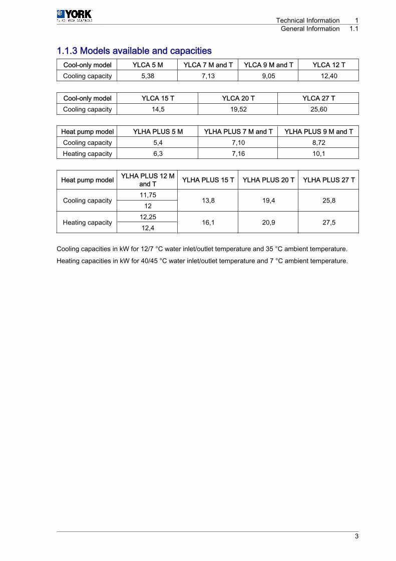
1.1.3 Models available and capacitiesCool-only model YLCA 5 M YLCA 7 M and T YLCA 9 M and T YLCA 12 TCooling capacity 5,38 7,13 9,05 12,40
Cool-only model YLCA 15 T YLCA 20 T YLCA 27 TCooling capacity 14,5 19,52 25,60
Heat pump model YLHA PLUS 5 M YLHA PLUS 7 M and T YLHA PLUS 9 M and TCooling capacity 5,4 7,10 8,72Heating capacity 6,3 7,16 10,1
Heat pump model YLHA PLUS 12 Mand T YLHA PLUS 15 T YLHA PLUS 20 T YLHA PLUS 27 T
Cooling capacity11,75
13,8 19,4 25,812
Heating capacity12,25
16,1 20,9 27,512,4
Cooling capacities in kW for 12/7 °C water inlet/outlet temperature and 35 °C ambient temperature.
Heating capacities in kW for 40/45 °C water inlet/outlet temperature and 7 °C ambient temperature.
Technical Information 1General Information 1.1
3

1.1.4 Features and advantagesFeatures• R-410A coolant• Compact size• Low height and weight• Factory-tested equipment.• Accessibility• Easy maintenance• Microprocessor for control and alarms• Manufactured to ISO 9001• Variable speed fan• Option to omit inertia tank• Connection for communications
Advantages• Does not harm the ozone layer• Minimum footprint• Space for installing on terraces• Operating quality control• Easy maintenance• Operator safety• Easy and safe operation• High quality level• Low sound level and condensation control• For installations with low water volume• Ideal for building management
Dynamic Set Point and omission of inertia tank
The control system of the YLCA/YLHA PLUS 5 to 27 includes the Dynamic Set Point and Omission ofInertia Tank.
Dynamic Set Point: Modifies the set point for the control of the water temperature according to the outdoortemperature. The objective is to prevent an excessive difference in temperature between the interior andexterior of the air-conditioned area. If there is a large difference, this may result in discomfort or thermalshock for the users entering and leaving the area and could even endanger their health. In addition, thisfunction, which increases the set point during the summer cycle and reduces it in the winter cycle, sig‐nificantly contributes to the system's energy savings.
Omission of inertia tank: This function increases the temperature differential which, when added to thecontrol set point, adjusts the stop/start cycles of the compressor when the unit is operating with a lowload. It uses the length of the compressor operating cycles as reference. Therefore, when the watertemperature falls quickly, it delays the stopping of the compressor by simulating the inertia tank function,thus avoiding too many stop / start cycles of the unit. This function, although slightly reducing the accuracyof the water temperature control, makes the use of the inertia tank unnecessary.
1 Technical Information1.1 General Information
4

1.1.5 Technical specificationsThese units are supplied completely factory-assembled and with all coolant tubing and wiring ready forinstallation on site. After mounting, these units must go through an operational test with water. Coolantleaks will also be checked during this process.
Sheeting casing
The units are made of galvanized steel sheeting and anticorrosion nuts and bolts. Panels can be removedfor access to internal components. The casing parts are painted with white RAL9001 oven-baked poly‐merized enamel.
Compressors
Hermetic Scroll compressors are used, mounted on anti-vibration supports. These compressors areequipped with internal devices that protect them against high operating temperatures. The sump heatersoperate only when the compressor is inoperative.
Water side heat exchanger
Comprises a stainless steel plate exchanger, adequately insulated by a layer of closed-cell elastomerfoam. The coolant side of said exchanger accepts an operating pressure of 52 bar, whereas the waterside accepts 10 bar. When the unit includes a hydro kit, maximum admissible pressure on the water sideis 6 bar (adjustment of the tank safety valve).
Air side heat exchanger
Made up of two notched aluminium blue fin coils and grooved copper tubing mechanically expandedwithin the fin assembly.
Fans
Of the axial and low sound level type. Equipped with single-phase motors with IP54 protection. Thesemotors allow speed control by means of a phase cut-out shifter controlled by the unit controller. Thisallows unit operation at low ambient temperatures (-10°C). On cool only units with an optional low ambienttemperature kit can reach ‑18°C. On heat pumps, the fan will remain inoperative during defrosting.
Electrical and control panel
Located inside the machine, and with IP44 protection. The operating and control components are factorymounted, wired and tested. This control panel is equipped with an external locking isolator that turns thepower supply off. Inside are the contactors for the compressor and the pump, the transformer, thermalmagnetic protectors, the speed control, connecting strip and the keyboard-display with the unit controls.
Control keyboard-display
This device is accessible through an external leak-tight plastic cover. This is an easy-to-use control withthree access levels: direct, user (password) and factory (password). For further information, please seeOperating instructions µC2, see on page 47.
Cooling circuit
The cool only unit cooling circuit includes: Schrader valves on the high, low and liquid sides, expansionvalve, filter dryer, sight glass (YLCA 20 to 27), high and low pressure switches, service valves to isolatethe condenser (YLCA 27) and an expansion restrictor (YLCA 5 to 15).The heat pump model includes: Schrader valves on the high, low and liquid sides, two expansion re‐strictors (YLHA PLUS 5 to 15), two expansion valves, high and low pressure switches, dryer filter, sightglass (YLHA PLUS 20 to 27), four-way valve (energised during the summer cycle and during defrostcycles), check valves (YLHA PLUS 20 to 27), service valves for isolating the condenser (YLHA PLUS27), an expansion valve for the heat cycle and a liquid vessel. The suction tubing is coated with closed-cell elastomer.
Technical Information 1General Information 1.1
5

Hydro kit (pack)
These units include a pack assembled with the components of a hydro kit. This assembly is located withinthe unit frame and does not increase the footprint of same. It includes the following components: centri‐fugal pump, expansion tank loaded with nitrogen at 1,5 bar, safety valve set to 6 bar, flow switch, airbleed valve and drain valve. Also includes a mesh filter for the water circuit. This filter is supplied loosefor installation at the most convenient point.
Soft Start
The models YLHA PLUS 5, 7, 9 and 12 MCS have an electronic starter specially designed to limit thestarter intensity point in the single-phase Scroll compressors.
1 Technical Information1.1 General Information
6

Options and accessoriesRemote control
Wall-mounted remote control unit with keyboard for cool/heat and ON/OFF functions. Includes powersupply, alarm and cool/heat LEDs. Maximum cable length: 50 m.
Remote terminal
For total access and control of the system by means of the display and buttons. It allows for selection ofcool, heat and off functions. Operating parameters can also be modified and the system can also besupervised. Can be installed at a maximum distance of 1040 m.
BMS connections
By means of a serial board, it is possible to connect the system to a standard RS485 monitoring network.
Low ambient temperature kit (YLCA 5 to 15)
Includes a pressure transducer to control condensation pressure at low ambient temperatures (-18 °C).
This component is standard in models YLCA 20 to 27 and YLHA PLUS 5 to 27.
High pressure fans
Inertia tank
With or without built-in auxiliary heater.
Protecting grids
To protect the coils from possible impacts. Made of steel rods and painted with oven baked polymerizedwhite enamel (RAL9001).
N O T ESee specific documentation for options and accessories.
Technical Information 1General Information 1.1
7
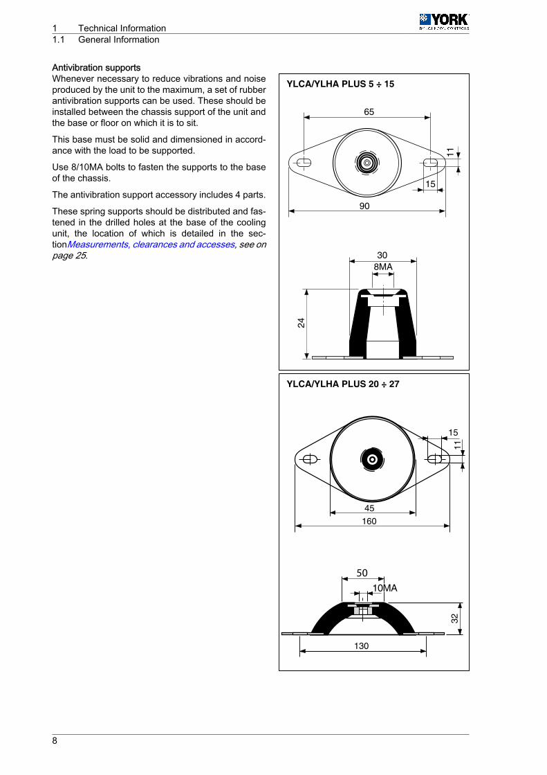
Antivibration supportsWhenever necessary to reduce vibrations and noiseproduced by the unit to the maximum, a set of rubberantivibration supports can be used. These should beinstalled between the chassis support of the unit andthe base or floor on which it is to sit.
This base must be solid and dimensioned in accord‐ance with the load to be supported.
Use 8/10MA bolts to fasten the supports to the baseof the chassis.
The antivibration support accessory includes 4 parts.
These spring supports should be distributed and fas‐tened in the drilled holes at the base of the coolingunit, the location of which is detailed in the sec‐tionMeasurements, clearances and accesses, see onpage 25.
YLCA/YLHA PLUS 5 ÷ 15
11
15
65
90
24
308MA
YLCA/YLHA PLUS 20 ÷ 27
50
1 Technical Information1.1 General Information
8
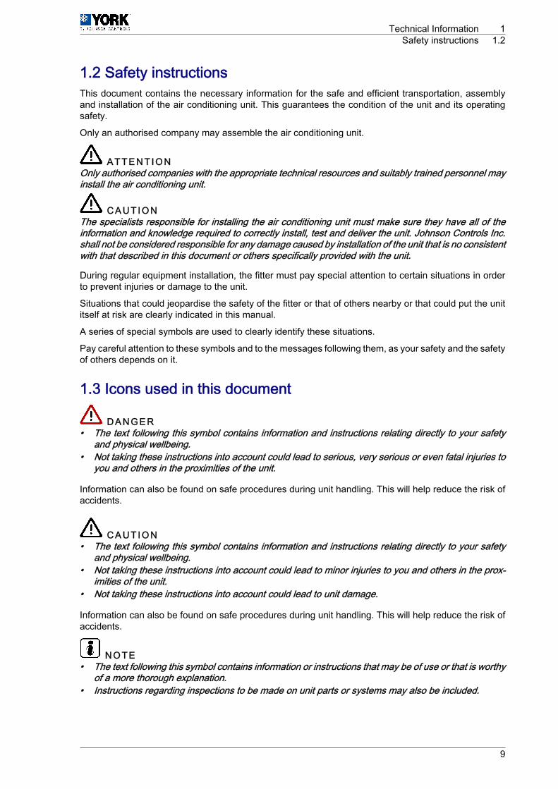
1.2 Safety instructionsThis document contains the necessary information for the safe and efficient transportation, assemblyand installation of the air conditioning unit. This guarantees the condition of the unit and its operatingsafety.
Only an authorised company may assemble the air conditioning unit.
A T T E N T I O NOnly authorised companies with the appropriate technical resources and suitably trained personnel mayinstall the air conditioning unit.
C A U T I O NThe specialists responsible for installing the air conditioning unit must make sure they have all of theinformation and knowledge required to correctly install, test and deliver the unit. Johnson Controls Inc.shall not be considered responsible for any damage caused by installation of the unit that is no consistentwith that described in this document or others specifically provided with the unit.
During regular equipment installation, the fitter must pay special attention to certain situations in orderto prevent injuries or damage to the unit.
Situations that could jeopardise the safety of the fitter or that of others nearby or that could put the unititself at risk are clearly indicated in this manual.
A series of special symbols are used to clearly identify these situations.
Pay careful attention to these symbols and to the messages following them, as your safety and the safetyof others depends on it.
1.3 Icons used in this document
D A N G E R• The text following this symbol contains information and instructions relating directly to your safety
and physical wellbeing.• Not taking these instructions into account could lead to serious, very serious or even fatal injuries to
you and others in the proximities of the unit.
Information can also be found on safe procedures during unit handling. This will help reduce the risk ofaccidents.
C A U T I O N• The text following this symbol contains information and instructions relating directly to your safety
and physical wellbeing.• Not taking these instructions into account could lead to minor injuries to you and others in the prox‐
imities of the unit.• Not taking these instructions into account could lead to unit damage.
Information can also be found on safe procedures during unit handling. This will help reduce the risk ofaccidents.
N O T E• The text following this symbol contains information or instructions that may be of use or that is worthy
of a more thorough explanation.• Instructions regarding inspections to be made on unit parts or systems may also be included.
Technical Information 1Safety instructions 1.2
9

1.4 Instructions for storage, transport, loading and unloading ofthe unit
C A U T I O NOutdoor units must be moved and stored vertically to prevent oil from leaking from the compressor.
Delivery inspection
The unit should be carefully inspected for visible damage or abnormalities as soon as it is received.
Any abnormalities or damage to the unit should be communicated to both the transportation and insur‐ance company in writing.
Storage instructions
The unit should be stored in a place suitable to the purpose (warehouse or similar), protected from theweather, water, humidity and dust.
Cover the unit with a canvas of a suitable size.
The unit should be appropriately protected from knocks and dust, ensuring the protective parts it wassupplied with remain in place. Where these are not in place, establish the necessary protections and/orbarriers to keep vehicles or fork-lift trucks away.
Transport, loading and unloading of the unit
The units should only be handled by personnel from the company responsible for their installation.
Transport of the unit should be in such a manner that no damage is caused by faulty or inadequatemooring to the bed or body of the vehicle.
Where necessary, protect all of the edges of the unit against knocks and scratches and moor it to thebed or body of the vehicle using suitable textile belts or slings to keep it perfectly still.
Loading and unloading the unit from a truck or trailer should be on flat, solid ground using an appropriatecrane with sufficient capacity.
1.4.1 InspectionUpon reception, inspect the goods and notify the carrier and the insurance company, in writing, of anypossible damage during transportation.
1.4.2 Disposal of packagingThe packaging is recyclable. Dispose of it in the appropriate place or take it to an appropriate collectioncentre. Respect the regulations in force for this type of waste in the country where the unit is beinginstalled.
Packaging remains must be correctly disposed of. Improper disposal of packaging generates environ‐mental problems that affect human life.
1 Technical Information1.4 Instructions for storage, transport, loading and unloading of the unit
10
1.4.3 Disposal of the unitWhen removing the unit, the components must be ecologically recovered. The cooling circuit is full ofcoolant that must be extracted and delivered to the gas manufacturer for recycling.
A T T E N T I O NThe refrigerant gas contains greenhouse-effect fluorinated gas covered by the Kyoto protocol.Please see the specifications plate for type of gas and quantity per system.GWP (Global Warning Potential): 2088
There will be oil left in the hermetic compressor, therefore it must be delivered with the circuit sealed.
The air conditioner shall be deposited in the area established by local authorities, to facilitate its selectiverecovery.
1.4.4 HandlingThe unit must be moved using the metal rails provided for its installation and transport
1.5 Selection guide (YLCA/YLHA)Necessary informationThe following information is needed to select a YLCA/YLHA water cooling unit:1 Cooling capacity needed2 Design cold water inlet and outlet temperatures.3 Design water flow rate, if one of the temperatures of Point 2 above is unknown.4 Design inlet temperature of air to the condenser. Normally, this will be the design ambient temperature
of summer air, unless influenced by the situation or other factors.5 Altitude above sea level.6 Design fouling factor of the evaporator.
N O T EPoints 1, 2 and 3 should be related by means of the following formulae:
Cooling capacity kW =l/h cold water x differential °C
860
Technical Information 1Selection guide (YLCA/YLHA) 1.5
11

SELECTION EXAMPLE
A cooler is required to chill water from 13°C to 7°C, with a cooling capacity of 5 kW.
There are also other design conditions:• Inlet ambient air in the condenser 35 °C• Fouling factor: 0,044 m2 °C/kW• Altitude: Sea level
From a quick glance at the table Cooling capacities YLCA 5 ÷ 27, see on page 35 it can be seen thata YLCA 5 gives approximately the required capacity of 5,38 kW.
As the factors appearing in tables Fouling factors, see on page 16 and Altitude factors, see on page19 are not applicable, the conditions will be as follows:• Cooling capacity: 5,38 kW• Power consumed: 1,87 kW• Water temperature: 13°C to 7°C (Temp. difference of 6)
Water flow rate =5,38 x 860
= 771 l/h6
Available pressure in the unit's hydraulic circuit:• From table Pressure available for the hydraulic circuit and pressure drop in the hydraulic circuit (with‐
out filter mounted), see on page 20 we infer that the YLCA 5 MC, with a flow rate of 771 l/h, has anavailable pressure of 56 kPa.
Pressure drop in filter:• From table Pressure drop in filters, see on page 21 we infer that with a flow rate of 771 l/h, there is
a pressure drop of 1,3 kPa.
YLHA PLUS selection method1 Establish the correct size of YLHA PLUS by selecting the model from the tablesHeating capacities
YLHA 5 ÷ 27, see on page 34 and Cooling capacities YLCA 5 ÷ 27, see on page 35 that is closestto the cooling and heating capacities required in design conditions of the water outlet temperatureand air inlet temperature.
2 Apply fouling correction factors (table Fouling factors, see on page 16) and height correction factors(table Altitude factors, see on page 19) to the capacity and power values shown in the correspondingtables of capacity for the cool and heat modes. Make sure the corrected capacity is still sufficient foryour needs.
3 Using the corrected capacities of the unit, select the design temperature differential or the flow rate.4 Check to make sure that these selections are within the YLCA/YLHA PLUS operating limits.
1 Technical Information1.5 Selection guide (YLCA/YLHA)
12
YLHA PLUS SELECTION EXAMPLE
A YLHA PLUS 5 heat pump operating at a 35 °C ambient temperature should cool water from 13 °C to7 °C, with a 5 kW cooling capacity.
A 4 kW heating capacity is required in 0 °C design ambient temperature and a hot water outlet temper‐ature of 45 °C.
The fouling factor is 0,044 m2 °C/kW, with the unit operating at sea level (no corrections). From a quickglance at the tablesHeating capacities YLHA 5 ÷ 27, see on page 34 and Cooling capacities YLCA 5÷ 27, see on page 35 we see that a YLHA PLUS 5 heat pump approximately gives the required ca‐pacities:• Cooling capacity = 5,4 kW• Total unit absorbed power = 1,91 kW• Cold water temperature = 13 °C to 7 °C (temp. diff. of 6 °C)• Hot and cold water flow rate = 774 l/h• Heating capacity = 4,15 kW• Total unit absorbed power in heat mode = 1,88 kW• Hot water outlet temperature = 45 °C
Hot water temp. dif‐ferential =
4,15 x 860= 4,60 °C
774
Thus, hot water return temperature is = 40,4 °C
All values are within operating limits:• Available pressure in hydraulic circuit of a unit with pack:• From table Pressure available for the hydraulic circuit and pressure drop in the hydraulic circuit (with‐
out filter mounted), see on page 20 we infer that the YLHA PLUS 5 MC, with a flow rate of 748 l/h,has an available pressure of 56,5 kPa.
• Pressure drop in filter.– From table Pressure drop in filters, see on page 21, 1" filter, we infer that with a 748 l/h flow rate,
said filter has a pressure drop of 1,2 kPa.
Technical Information 1Selection guide (YLCA/YLHA) 1.5
13
1.5.1 Selection guide with glycol (cool only units)Necessary informationThe following information is needed to select a YLCA cooling unit:1 Cooling capacity needed2 Design cold water/glycol inlet and outlet temperatures.3 Design water/glycol flow rate.4 Design inlet temperature of air to the condenser. Normally, this will be the design ambient temperature
of summer air, unless influenced by the situation or other factors.5 Altitude above sea level.6 Design fouling factor of the evaporator.
N O T EPoints 1, 2 and 3 should be related by means of the following formulae:
Capacity (kW) =Temp. diff. (°C) x Flow rate (litres/sec.)
Glycol factor
Temp. differential (°C) = Liquid Inlet Temp. ‑ Liquid Outlet Temp.
To determine the glycol factor, please see Glycol concentration and correcting tables, see on page17 (Recommended ethylene glycol concentrations) for ethylene glycol or (Recommended propyleneglycol concentrations) for propylene glycol. For design outlet temperature, please see the recommendedglycol concentration and the glycol factor in this concentration. This is the minimum concentration to beused for design outlet temperature. If a greater concentration is required, the glycol factor can be deter‐mined by means of Glycol concentration and correcting tables, see on page 17 (Ethylene glycol in otherconcentrations) or (Propylene glycol in other concentrations).
Selection method1 Determine the correct cooling unit model by selecting the one that is closest to the capacities required
by the design conditions of the glycol outlet and air inlet temperatures.2 Apply the fouling correcting factors that correspond to the fouling, altitude and glycol concentration
factor, to the capacity and power values in the capacity tables. Make sure the corrected capacity isstill sufficient for your needs.
3 Using the corrected capacities of the cooler, set the design temperature range, or the flow rate, tobalance the formulae appearing in Selection guide (YLCA/YLHA), see on page 11.
4 Always recheck to make sure these selections are within the specified design limits.
Selection example
A cooler is required to chill ethylene glycol from 1 a to ‑4 °C, with an output of 3,5 kW.
The following design conditions are applicable:• Fouling factor: 0,088m °C/kW• Altitude: 1 200m• Ambient air: 30 °C• Glycol concentration: 30% w/w
For a ‑4 °C ethylene glycol outlet, the concentration recommended in Figure 1 is 30%. Therefore, thespecified concentration is appropriate.
From table Cooling capacities YLCA 5 ÷ 27 (35% ethylene glycol), see on page 36, we infer that aYLCA 5 unit, at the established design conditions, gives a capacity of 3,4 kW and a consumption of 1,35kW.
With the design fouling factor, use the capacity correcting factors x 0,987 and power x 0,995 (seeFoulingfactors, see on page 16).
On design altitude, apply the capacity correcting factors x 10,973 and power x 1,020 (seeAltitude fac‐tors, see on page 19).
1 Technical Information1.5 Selection guide (YLCA/YLHA)
14

On design glycol concentration, apply the capacity correcting factors x 1,015 and power x 1,005(seeCorrecting factors for other glycol concentrations, see on page 19).
Applying these factors to the selection: YLCA 5
Capacity = 3,44 x 0,987 x 0,973 x 1,015 = 3,35 kW
Comp. power = 1,35 x 0,995 x 1,020 x 1,005 = 1,37 kW
For the specified glycol concentration and a ‑4 °C outlet temperature, Figure 3 shows a 0,248 glycolfactor. Thus, the flow rate can be determined with the formula appearing in Selection guide (YLCA/YLHA), see on page 11.
3,35 [kW] =(1 ‑ (-4)) x Flow rate [l / s]
0,248
Flow rate =3,35 x 0,248
= 0,166 [l / s] or 598 [l / h]5
This covers the Limits of Use.
The evaporator pressure drop can be determined by taking the water pressure drop value for a YLCAunit and multiplying it by the correction factor (see Glycol concentration and correcting tables, see onpage 17) for a 30% concentration and an average temperature of ‑1,5 °C, i.e.:
-1,5 °C=1 + (-4)
2
42 kPa x 1,22 = 51,2 kPa.
Technical Information 1Selection guide (YLCA/YLHA) 1.5
15

1.6 Technical data1.6.1 Limits of use
Model
Voltage limits Inlet air temperature to thecoil DB Water outlet temperature Temperature difference be‐
tween water outlet and inlet
Nominal at 400Operating cycle Operating cycle
Minimum °C Maximum°C Minimum °C Maximum °C
Minimum °C Maximum °CMini‐mum
Maxi‐mum Cold Hea
t Cold Heat Cold Heat Cold Heat
YLCA342 436 -10(2)
-46
-5(1)
-15
-3 7YLHA
PLUS -15 20 30 50(3)
(1) At lower water temperatures, it is advisable to use glycol-type antifreeze mixtures. Minimumtemp. with glycol ‑5 °C.
(2) -18 °C with low temperature (optional in models YLCA 5, 7, 9, 12, 15).(3) 50 °C if the inlet air temp. is higher than 0 °C.
Prior to final approval of the installationCheck:• Voltage remains between 342 ‑ 436 V.A.
C A U T I O NThe cable used for the unit power supply must be H05 RN ‑ F
• Power supply cable cross-section is at least as indicated in the corresponding wiring diagrams. Thecable used for the unit power supply must be H05 RN-F.
• Operating instructions have been given to the user.• The warranty card has been filled out.• Maintenance instructions have been given, or a regular maintenance contract has been signed.
1.6.2 Correcting FactorsFouling factors
Evaporator
Fouling Factor m2 °C/kW Capacity factor compressorabsorbed power factor
0,044 1 10,088 0,987 0,9950,176 0,964 0,9850,352 0,926 0,962
1 Technical Information1.6 Technical data
16
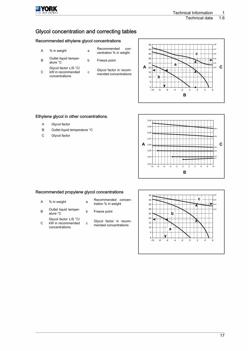
Glycol concentration and correcting tablesRecommended ethylene glycol concentrations
A % in weight a Recommended con‐centration % in weight
B Outlet liquid temper‐ature °C b Freeze point
CGlycol factor L/S °C/kW in recommendedconcentrations
c Glycol factor in recom‐mended concentrations
Ethylene glycol in other concentrations.
A Glycol factorB Outlet liquid temperature °CC Glycol factor
Recommended propylene glycol concentrations
A % in weight a Recommended concen‐tration % in weight
B Outlet liquid temper‐ature °C b Freeze point
CGlycol factor L/S °C/kW in recommendedconcentrations
c Glycol factor in recom‐mended concentrations
A a
b
c
C
B
A C
B
a
b
c
Technical Information 1Technical data 1.6
17

Propylene glycol in other concentrations
A Glycol factorB Outlet liquid temperature °CC Glycol factor
Ethylene glycol pressure drop correcting factor
A Correcting FactorB Average liquid temperature °CC Glycol concentration P/P
Propylene glycol pressure drop correcting factor
A Correcting FactorB Average liquid temperature °CC Glycol concentration P/P
A C
B
A C
B
A C
B
1 Technical Information1.6 Technical data
18
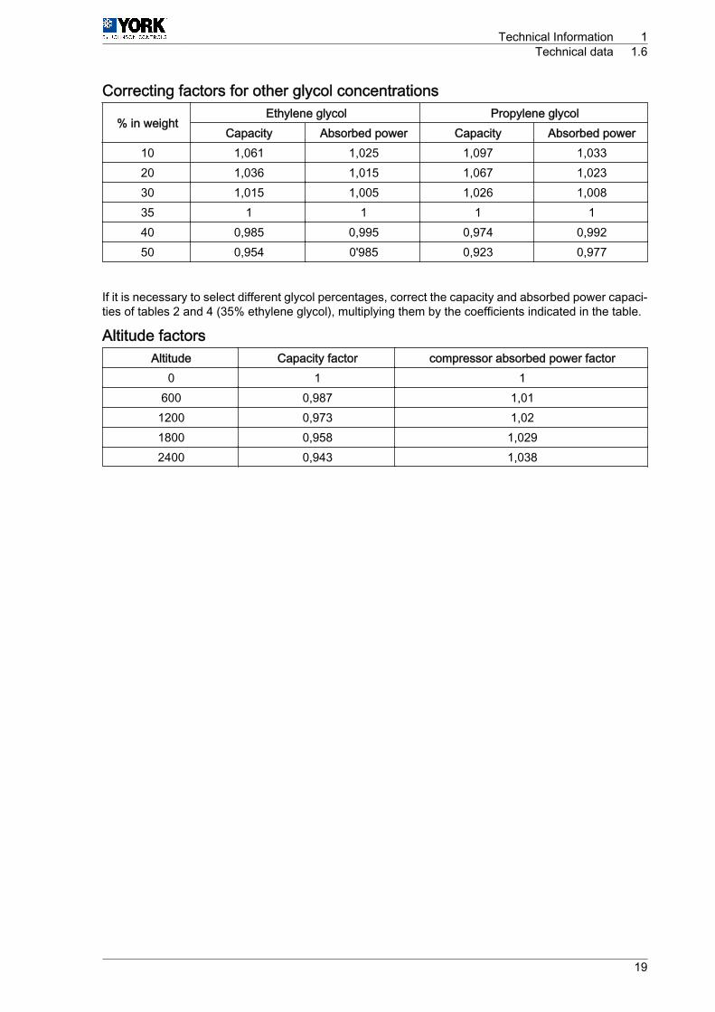
Correcting factors for other glycol concentrations
% in weightEthylene glycol Propylene glycol
Capacity Absorbed power Capacity Absorbed power10 1,061 1,025 1,097 1,03320 1,036 1,015 1,067 1,02330 1,015 1,005 1,026 1,00835 1 1 1 140 0,985 0,995 0,974 0,99250 0,954 0'985 0,923 0,977
If it is necessary to select different glycol percentages, correct the capacity and absorbed power capaci‐ties of tables 2 and 4 (35% ethylene glycol), multiplying them by the coefficients indicated in the table.
Altitude factorsAltitude Capacity factor compressor absorbed power factor
0 1 1600 0,987 1,011200 0,973 1,021800 0,958 1,0292400 0,943 1,038
Technical Information 1Technical data 1.6
19
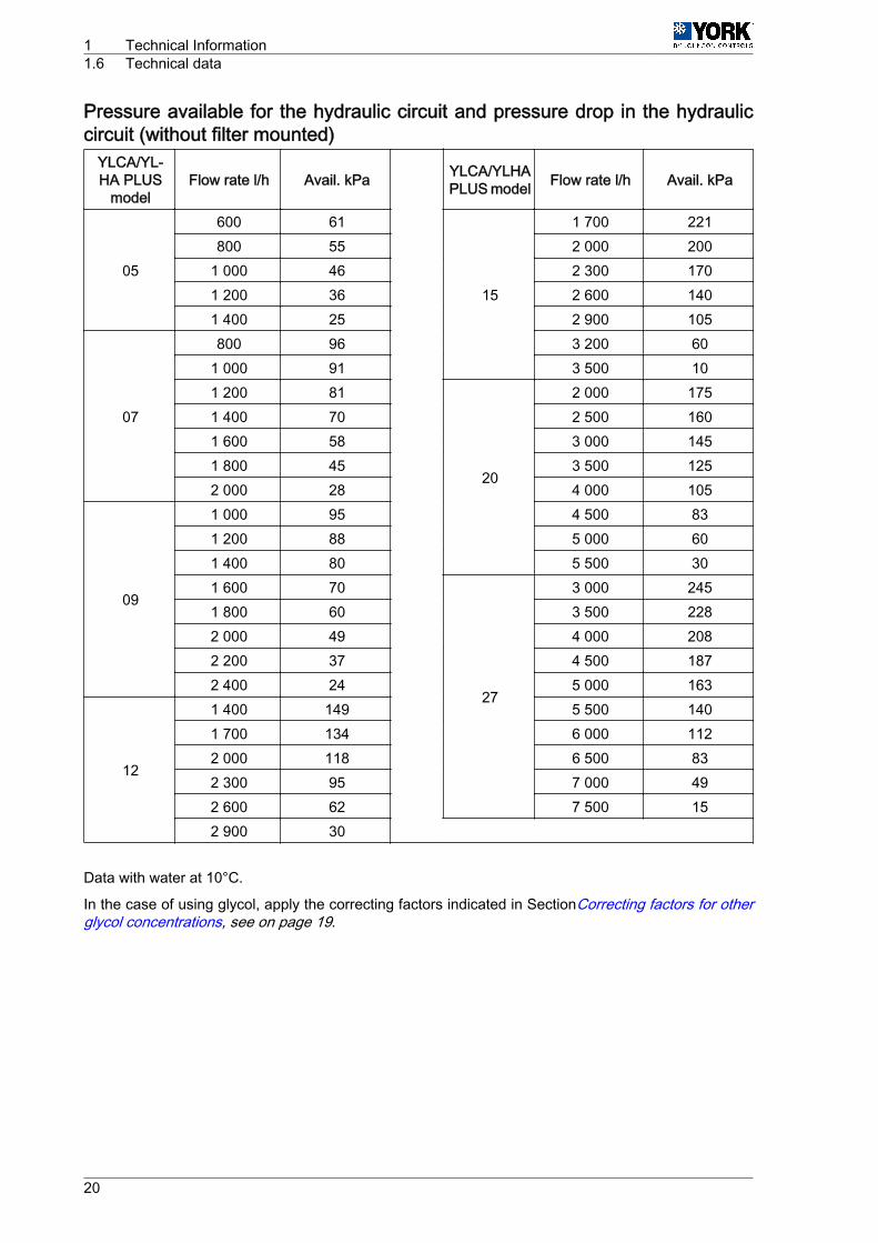
Pressure available for the hydraulic circuit and pressure drop in the hydrauliccircuit (without filter mounted)
YLCA/YL‐HA PLUS
modelFlow rate l/h Avail. kPa YLCA/YLHA
PLUS model Flow rate l/h Avail. kPa
05
600 61
15
1 700 221800 55 2 000 200
1 000 46 2 300 1701 200 36 2 600 1401 400 25 2 900 105
07
800 96 3 200 601 000 91 3 500 101 200 81
20
2 000 1751 400 70 2 500 1601 600 58 3 000 1451 800 45 3 500 1252 000 28 4 000 105
09
1 000 95 4 500 831 200 88 5 000 601 400 80 5 500 301 600 70
27
3 000 2451 800 60 3 500 2282 000 49 4 000 2082 200 37 4 500 1872 400 24 5 000 163
12
1 400 149 5 500 1401 700 134 6 000 1122 000 118 6 500 832 300 95 7 000 492 600 62 7 500 152 900 30
Data with water at 10°C.
In the case of using glycol, apply the correcting factors indicated in SectionCorrecting factors for otherglycol concentrations, see on page 19.
1 Technical Information1.6 Technical data
20
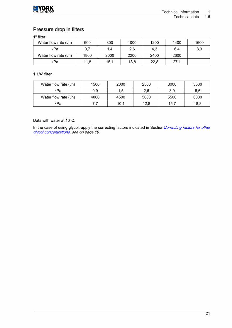
Pressure drop in filters1" filter
Water flow rate (l/h) 600 800 1000 1200 1400 1600kPa 0,7 1,4 2,6 4,3 6,4 8,9
Water flow rate (l/h) 1800 2000 2200 2400 2600 kPa 11,8 15,1 18,8 22,8 27,1
1 1/4" filter
Water flow rate (l/h) 1500 2000 2500 3000 3500kPa 0,9 1,5 2,6 3,9 5,6
Water flow rate (l/h) 4000 4500 5000 5500 6000kPa 7,7 10,1 12,8 15,7 18,8
Data with water at 10°C.
In the case of using glycol, apply the correcting factors indicated in SectionCorrecting factors for otherglycol concentrations, see on page 19.
Technical Information 1Technical data 1.6
21

1.6.3 Physical dataPhysical data, YLCA unitsPhysical data
YLCA (M and MC) YLCA (T and TC)
Characteristics 5 7 9 7 9 12 15 20 27
Cooling capacity kW 5,38 7,13 9,05 7,13 9,05 12,4 14,5 19,52 25,6
Capacity control %
Power supply V/ph 230.1.50 400.3.50
Max. unit power supply consumption kW 2,57 3,61 4,36 3,61 4,36 5,68 8 9,17 12,09
Max. unit current amperage A 11,75 17,1 23 7,6 8,25 11,6 15,8 18,1 23
EER 2,87 2,76 2,79 2,76 2,81 2,97 2,52 2,81 2,81
Compressor
Compressor power kW 1,73 2,41 3,2 2,41 3,2 3,8 5,38 6,57 8,73
Compressor amperage A 7,8 11,7 16 3,9 5,3 6,36 8,9 13 16,7
No. of compressors 1
Compressor type SCROLL
Oil charge l 1,1 1,25 1,95 1,66 2,51 3,25
Oil type POLYOL ESTER OIL
Compressor start-upcurrent A 60 82 97 35 48 51 74 95 118
Evaporator unit type PLATES
Fan
No. of fans 1 2
Fan diameter mm 450 560
Fan power W 140 170 2 x 185 2 x 175
Fan amperage A 0,6 0,8 2 x 0,87 2 x 0,85
Total air flow rate m³/h 2900 3150 6150 6300 7200
Sound power dB(A) 70 70 71 70 71 73 73 74 78
Sound pressure at 5 m dB(A) 44 44 45 44 45 47 47 48 51
Sound pressure at10 m dB(A) 40 40 41 40 41 43 43 44 48
Available static pres‐sure at nominal flowrate (without filter) (2)
kPa 51 80 78 80 75 115 152 134 191
Available static pres‐sure at nominal flowrate (with filter) (3)
kPa 49 75,5 71 75,5 67,5 113 149 129,5 182
Coolant
Coolant type R-410A
Coolant charge kg 2,08 2,55 2,25 2,55 2,15 3,17 3,1 5 7,8
No. of coolant circuits
Water circuit
Nominal water flow rate l/h 925 1225 1430 1225 1475 2065 2530 3360 4405
Min water volume inst.(1) l 15 20 25 20 25 35 45 55 75
Water connection, fe‐male 1" 1 1/4"
water filter, female 1" 1 1/4"
No. of pumps 1
Pump power W 160 210 400 490 390 755
Pump amperage A 0,65 0,95 1,8 2,15 1,1 1,34
Unit water content l 1 1,1 1,2 1,1 1,2 1,5 2 2,8 3,2
Volume of expansionvessel l 1 2 5 8
Safety valvesetting
MPa(bar)
0,6(6)
Dimensionsand weight
Weight (4)(5) kg 75 99 100 99 100 146 160 220 290
Length mm 905 1430 1876
Width mm 460 502
Height mm 762 965 1270
(1) Minimum volume of water in installation: In installations with smaller volumes, and under low load conditions, the function "Omission of inertia tank" is automaticallyactivated. As a result, the water temperature becomes less accurate as the total volume of water in the installation is reduced.
(2) Please enquire before applying values lower than those shown.
(3) Static pressure available, Eurovent certified. Pressure with clean filter.
(4) Weights for the empty unit.
1 Technical Information1.6 Technical data
22
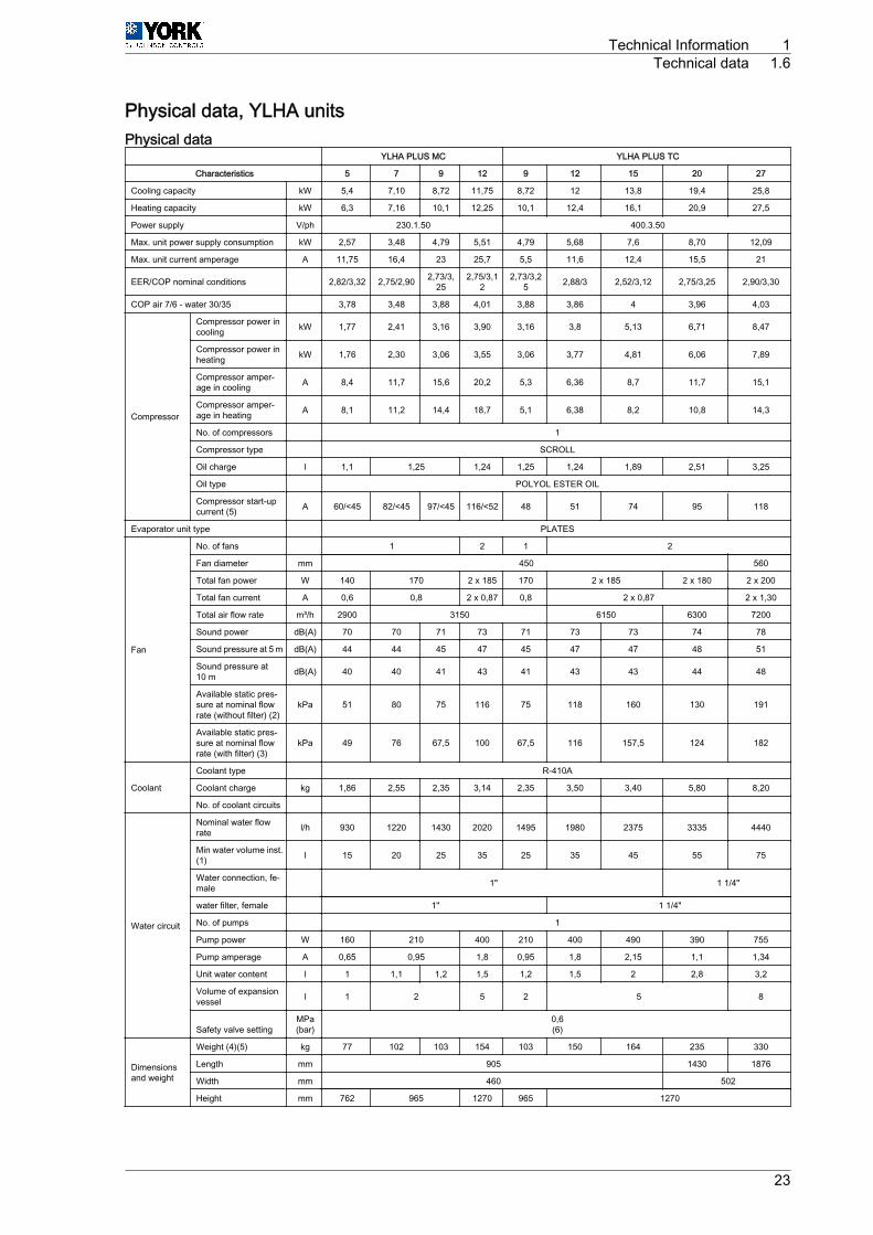
Physical data, YLHA unitsPhysical data
YLHA PLUS MC YLHA PLUS TC
Characteristics 5 7 9 12 9 12 15 20 27
Cooling capacity kW 5,4 7,10 8,72 11,75 8,72 12 13,8 19,4 25,8
Heating capacity kW 6,3 7,16 10,1 12,25 10,1 12,4 16,1 20,9 27,5
Power supply V/ph 230.1.50 400.3.50
Max. unit power supply consumption kW 2,57 3,48 4,79 5,51 4,79 5,68 7,6 8,70 12,09
Max. unit current amperage A 11,75 16,4 23 25,7 5,5 11,6 12,4 15,5 21
EER/COP nominal conditions 2,82/3,32 2,75/2,90 2,73/3,25
2,75/3,12
2,73/3,25 2,88/3 2,52/3,12 2,75/3,25 2,90/3,30
COP air 7/6 ‑ water 30/35 3,78 3,48 3,88 4,01 3,88 3,86 4 3,96 4,03
Compressor
Compressor power incooling kW 1,77 2,41 3,16 3,90 3,16 3,8 5,13 6,71 8,47
Compressor power inheating kW 1,76 2,30 3,06 3,55 3,06 3,77 4,81 6,06 7,89
Compressor amper‐age in cooling A 8,4 11,7 15,6 20,2 5,3 6,36 8,7 11,7 15,1
Compressor amper‐age in heating A 8,1 11,2 14,4 18,7 5,1 6,38 8,2 10,8 14,3
No. of compressors 1
Compressor type SCROLL
Oil charge l 1,1 1,25 1,24 1,25 1,24 1,89 2,51 3,25
Oil type POLYOL ESTER OIL
Compressor start-upcurrent (5) A 60/<45 82/<45 97/<45 116/<52 48 51 74 95 118
Evaporator unit type PLATES
Fan
No. of fans 1 2 1 2
Fan diameter mm 450 560
Total fan power W 140 170 2 x 185 170 2 x 185 2 x 180 2 x 200
Total fan current A 0,6 0,8 2 x 0,87 0,8 2 x 0,87 2 x 1,30
Total air flow rate m³/h 2900 3150 6150 6300 7200
Sound power dB(A) 70 70 71 73 71 73 73 74 78
Sound pressure at 5 m dB(A) 44 44 45 47 45 47 47 48 51
Sound pressure at10 m dB(A) 40 40 41 43 41 43 43 44 48
Available static pres‐sure at nominal flowrate (without filter) (2)
kPa 51 80 75 116 75 118 160 130 191
Available static pres‐sure at nominal flowrate (with filter) (3)
kPa 49 76 67,5 100 67,5 116 157,5 124 182
Coolant
Coolant type R-410A
Coolant charge kg 1,86 2,55 2,35 3,14 2,35 3,50 3,40 5,80 8,20
No. of coolant circuits
Water circuit
Nominal water flowrate l/h 930 1220 1430 2020 1495 1980 2375 3335 4440
Min water volume inst.(1) l 15 20 25 35 25 35 45 55 75
Water connection, fe‐male 1" 1 1/4"
water filter, female 1" 1 1/4"
No. of pumps 1
Pump power W 160 210 400 210 400 490 390 755
Pump amperage A 0,65 0,95 1,8 0,95 1,8 2,15 1,1 1,34
Unit water content l 1 1,1 1,2 1,5 1,2 1,5 2 2,8 3,2
Volume of expansionvessel l 1 2 5 2 5 8
Safety valve settingMPa(bar)
0,6(6)
Dimensionsand weight
Weight (4)(5) kg 77 102 103 154 103 150 164 235 330
Length mm 905 1430 1876
Width mm 460 502
Height mm 762 965 1270 965 1270
Technical Information 1Technical data 1.6
23

(1) Minimum volume of water in installation: In installations with smaller volumes, and under low load conditions, the function "Omission of inertia tank" is automaticallyactivated. As a result, the water temperature becomes less accurate as the total volume of water in the installation is reduced.
(2) Please enquire before applying values lower than those shown.
(3) Static pressure available, Eurovent certified. Pressure with clean filter.
(4) Weights for the empty unit.
(5) With Soft Start.
1.6.4 Electrical specifications
Model Power sup‐ply V.ph.Hz.
Compressor Fans Pump
Nominal A Start-up A Nominal kWNominal A Nominal W Nominal A Nominal W
Cold Heat Standard Soft Start Cold Heat
YLCA 5
230.1.50
7,80 -60 <45
1,73 -0,60 140 0,65 160
YLHA PLUS 5 7,80 8,10 1,73 1,76
YLCA 7 11,70 -82 <45
2,41 -
0,80 170 0,95 210YLHA PLUS 7 12,40 13,20 2,56 2,76
YLCA 9 17 -97 <45
3,20 -
YLHA PLUS 9 17 14,50 3,16 3,06
YLHA PLUS 12 16,30 14,80 116 <52 3,29 2,98 2 x 0,87 2 x 185 1,80 400
YLCA 7
400.3.50
3,90 -35
- 2,41 -
0,80 170 0,95 210YLHA PLUS 7 4,10 4,80 - 2,56 2,76
YLCA 9 5,70 -48
- 3,20 -
YLHA PLUS 9 6 5,80 - 3,16 3,06
YLCA 12 6,36 -51
- 3,80 -
2 x 0,87 2 x 185
1,80 400YLHA PLUS 12 6,36 6,38 - 3,80 3,77
YLCA 15 8,90 -74
- 5,38 -2,15 490
YLHA PLUS 15 8,70 8,90 - 5,25 5,23
YLCA 20 13 -95
- 6,65 -2 x 0,8 2 x 170 1,10 390
YLHA PLUS 20 12,20 11,70 - 6,62 6,26
YLCA 27 16,70 -118
- 8,73 -2 x 0,85 2 x 175 1,34 755
YLHA PLUS 27 16,70 16 - 8,73 8,24
1 Technical Information1.6 Technical data
24

1.7 Measurements, clearances and accesses
1.7.1 ClearancesWhen installing each unit, clearances should be left for:1 Air inlet and discharge.2 Maintenance servicing.3 Power supply connections.
To operate correctly, all minimum clearances shown on the general dimension diagrams should be re‐spected, with regard to the possible obstruction of air circulation or of the work of an operator.
Minimum technical clearance YLCA 5, 7, 9, 12 and 15
600
300
800
15040
0
N O T EDistances in millimetres
Technical Information 1Measurements, clearances and accesses 1.7
25

Minimum technical clearance YLCA/YLHA PLUS 20 and 27
600300
300
800
A
A Water inlet and outlet
N O T EDistances in millimetres
1 Technical Information1.7 Measurements, clearances and accesses
26
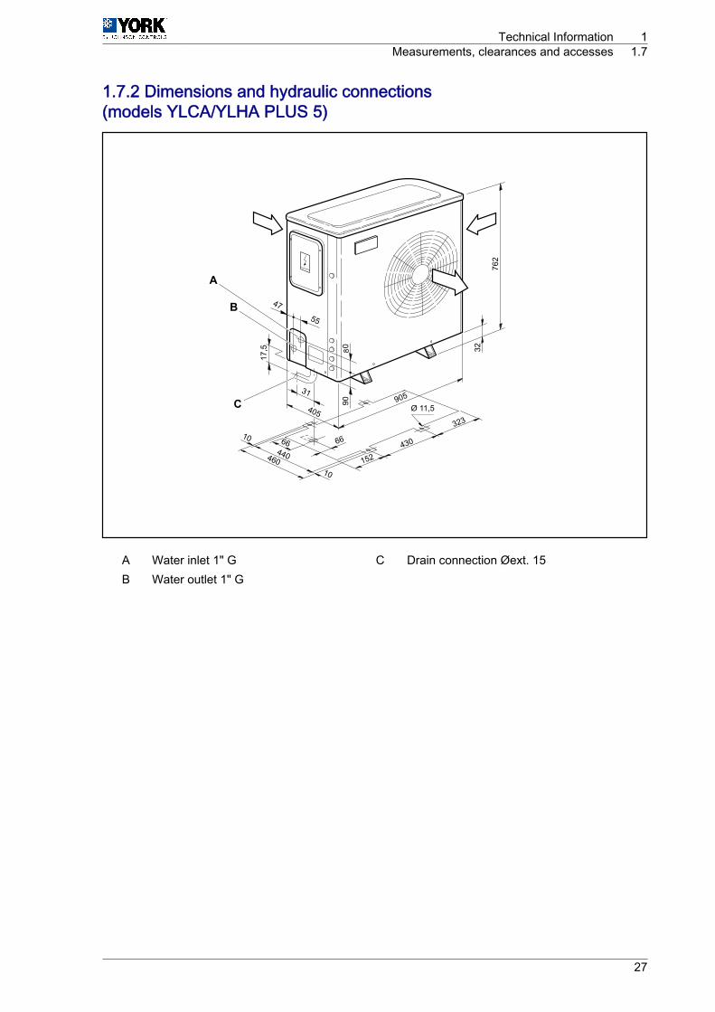
1.7.2 Dimensions and hydraulic connections(models YLCA/YLHA PLUS 5)
762
32
905405
10
323
152430
440
10
460
17,5
31
66 66
9080
55
47
Ø 11,5
A
B
C
A Water inlet 1" G C Drain connection Øext. 15B Water outlet 1" G
Technical Information 1Measurements, clearances and accesses 1.7
27
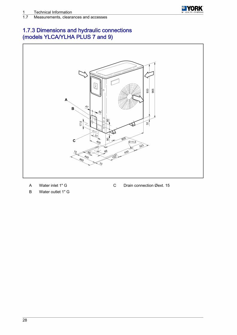
1.7.3 Dimensions and hydraulic connections(models YLCA/YLHA PLUS 7 and 9)
9055
47
32
905405
323
152430
440
10
46010
Ø 11,5
17,5
31
66 6693
3
965
80
A
B
C
A Water inlet 1" G C Drain connection Øext. 15B Water outlet 1" G
1 Technical Information1.7 Measurements, clearances and accesses
28

1.7.4 Dimensions and hydraulic connections(models YLCA/YLHA PLUS 12 and 15)
1270
3212
38
405905
323
152430
440
10
46010
Ø 11,5
17,5
31
66 66
9067
555
26
A
B
C
A Water inlet 1" G C Drain connection Øext. 15B Water outlet 1" G
Technical Information 1Measurements, clearances and accesses 1.7
29

1.7.5 Dimensions and hydraulic connections(models YLCA/YLHA PLUS 20 and 27)
YLCA/YLHA PLUS 20 & 27
1270
577
5090
43,5
43,5
415
502
16089
11/4”GF
75Ø38D
C
11/4”GF
18 18
15
15
A
B
4
4
3
1
2
5
a
c
d
b
a Rear view 1 Water outletb Side view 2 Water inletc Front view 3 Air outletd Upper view 4 Air inlet 5 Water drainage
Model A B C DYLCA/YLHA PLUS 20 1430 1394 136 428YLCA/YLHA PLUS 27 1876 1840 144 432
1 Technical Information1.7 Measurements, clearances and accesses
30

1.8 Capacities YLHA1.8.1 Cooling capacities YLHA 5 ÷ 27
YLHAPLUS
Wateroutlettemp°C
Outdoor ambient temperature °C DB (80% RH)
20 25 30 32 35 40 43 46
Cap. Abs.power Cap. Abs.
power Cap. Abs.power Cap. Abs.
power Cap. Abs.power Cap. Abs.
power Cap. Abs.power Cap. Abs.
power
kW kW kW kW kW kW kW kW kW kW kW kW kW kW kW kW
5 M
5 6,00 1,50 5,70 1,58 5,25 1,70 5,10 1,80 5,06 1,90 4,49 2,10 4,22 2,23 3,88 2,50
6 6,25 1,50 5,80 1,59 5,45 1,71 5,29 1,81 5,23 1,90 4,77 2,11 4,47 2,23 4,07 2,50
7 6,50 1,51 5,90 1,60 5,60 1,72 5,48 1,81 5,40 1,91 5,06 2,12 4,72 2,24 4,22 2,51
8 6,60 1,51 6,00 1,61 5,67 1,73 5,59 1,82 5,55 1,92 5,21 2,13 4,87 2,26 4,41 2,51
10 6,70 1,51 6,20 1,61 5,86 1,75 5,70 1,84 5,70 1,95 5,36 2,16 5,10 2,29 4,64 2,52
12 6,80 1,52 6,40 1,62 6,01 1,76 5,86 1,85 5,82 1,97 5,51 2,19 5,32 2,32 4,98 2,52
15 7,00 1,52 6,70 1,63 6,24 1,78 6,08 1,87 5,97 2,00 5,70 2,22 5,59 2,37 5,30 2,53
7 M
5 7,60 2,06 7,30 2,14 6,90 2,30 6,70 2,43 6,65 2,56 5,90 2,84 5,55 3,01 5,10 3,20
6 7,75 2,07 7,45 2,15 7,10 2,31 6,95 2,44 6,88 2,57 6,28 2,85 5,88 3,02 5,35 3,24
7 7,90 2,07 7,60 2,16 7,30 2,32 7,20 2,45 7,10 2,58 6,65 2,86 6,20 3,03 5,55 3,28
8 8,05 2,08 7,75 2,17 7,45 2,34 7,35 2,46 7,30 2,60 6,85 2,88 6,40 3,05 5,80 3,32
10 8,30 2,08 7,90 2,18 7,70 2,36 7,50 2,48 7,50 2,63 7,05 2,92 6,70 3,09 6,10 3,38
12 8,55 2,09 8,20 2,19 7,90 2,38 7,70 2,50 7,65 2,66 7,25 2,96 7,00 3,14 6,55 3,42
15 8,90 2,09 8,50 2,20 8,20 2,40 8,00 2,53 7,85 2,70 7,50 3,00 7,35 3,20 6,97 3,48
9 M
5 9,31 2,76 8,95 2,87 8,45 3,08 8,21 3,26 8,15 3,43 7,23 3,81 6,80 4,04 6,25 4,29
6 9,50 2,78 9,13 2,88 8,70 3,10 8,52 3,27 8,42 3,45 7,69 3,82 7,20 4,04 6,56 4,35
7 9,68 2,78 9,31 2,90 8,95 3,11 8,82 3,29 8,70 3,46 8,15 3,84 7,60 4,06 6,80 4,40
8 9,86 2,79 9,50 2,91 9,13 3,14 9,01 3,30 8,95 3,49 8,39 3,86 7,84 4,09 7,11 4,45
10 10,17 2,79 9,68 2,92 9,44 3,16 9,19 3,33 9,19 3,53 8,64 3,92 8,21 4,14 7,47 4,53
12 10,48 2,80 10,05 2,94 9,68 3,19 9,44 3,35 9,37 3,57 8,88 3,97 8,58 4,21 8,03 4,59
15 10,91 2,80 10,42 2,95 10,05 3,22 9,80 3,39 9,62 3,62 9,19 4,02 9,01 4,29 8,54 4,67
9 T
5 9,31 2,76 8,95 2,87 8,45 3,08 8,21 3,26 8,15 3,43 7,23 3,81 6,80 4,04 6,25 4,29
6 9,50 2,78 9,13 2,88 8,70 3,10 8,52 3,27 8,42 3,45 7,69 3,82 7,20 4,04 6,56 4,35
7 9,68 2,78 9,31 2,90 8,95 3,11 8,82 3,29 8,70 3,46 8,15 3,84 7,60 4,06 6,80 4,40
8 9,86 2,79 9,50 2,91 9,13 3,14 9,01 3,30 8,95 3,49 8,39 3,86 7,84 4,09 7,11 4,45
10 10,17 2,79 9,68 2,92 9,44 3,16 9,19 3,33 9,19 3,53 8,64 3,92 8,21 4,14 7,47 4,53
12 10,48 2,80 10,05 2,94 9,68 3,19 9,44 3,35 9,37 3,57 8,88 3,97 8,58 4,21 8,03 4,59
15 10,91 2,80 10,42 2,95 10,05 3,22 9,80 3,39 9,62 3,62 9,19 4,02 9,01 4,29 8,54 4,67
12 M
5 12,63 3,36 12,08 3,48 11,60 3,81 11,09 4,02 11,01 4,24 9,76 4,70 9,18 4,98 8,60 5,28
6 12,90 3,37 12,33 3,50 11,90 3,82 11,50 4,04 11,38 4,25 10,38 4,71 9,72 4,99 8,85 5,32
7 13,40 3,39 12,99 3,52 12,43 3,84 11,92 4,05 11,75 4,27 11,01 4,73 10,26 5,01 9,18 5,34
8 13,55 3,44 12,83 3,59 12,55 3,87 12,16 4,07 12,08 4,30 11,34 4,77 10,59 5,05 9,60 5,36
10 13,74 3,44 13,07 3,61 12,74 3,91 12,41 4,10 12,41 4,35 11,67 4,83 11,09 5,11 10,10 5,40
12 14,15 3,46 13,57 3,62 13,07 3,94 12,74 4,14 12,66 4,40 12,00 4,90 11,58 5,20 10,84 5,44
15 14,73 3,46 14,07 3,64 13,57 3,97 13,24 4,19 12,99 4,47 12,41 4,97 12,16 5,30 11,53 5,52
12 T
5 12,90 3,27 12,34 3,39 11,85 3,71 11,32 3,92 11,24 4,13 9,97 4,58 9,38 4,85 8,78 5,14
6 13,17 3,28 12,59 3,41 12,15 3,72 11,75 3,93 11,62 4,14 10,61 4,59 9,93 4,86 9,04 5,18
7 13,69 3,30 13,27 3,43 12,69 3,74 12,17 3,95 12,00 4,16 11,24 4,61 10,48 4,89 9,38 5,20
8 13,84 3,35 13,10 3,50 12,82 3,77 12,42 3,97 12,34 4,19 11,58 4,64 10,82 4,92 9,80 5,22
10 14,03 3,35 13,35 3,52 13,01 3,81 12,68 4,00 12,68 4,24 11,92 4,71 11,32 4,98 10,31 5,26
12 14,45 3,37 13,86 3,53 13,35 3,84 13,01 4,03 12,93 4,29 12,25 4,77 11,83 5,06 11,07 5,30
15 15,04 3,37 14,37 3,55 13,86 3,87 13,52 4,08 13,27 4,35 12,68 4,84 12,42 5,16 11,78 5,38
15 T
5 14,83 4,30 14,19 4,46 13,62 4,88 13,02 5,15 12,93 5,43 11,47 6,02 10,79 6,38 10,10 6,76
6 15,15 4,32 14,48 4,48 13,98 4,90 13,51 5,17 13,36 5,45 12,20 6,03 11,42 6,39 10,40 6,82
7 15,74 4,34 15,26 4,51 14,60 4,92 13,99 5,19 13,80 5,47 12,93 6,06 12,05 6,42 10,79 6,84
8 15,91 4,41 15,06 4,60 14,74 4,96 14,29 5,22 14,19 5,51 13,31 6,11 12,44 6,47 11,27 6,87
10 16,13 4,41 15,35 4,62 14,97 5,00 14,58 5,26 14,58 5,58 13,70 6,19 13,02 6,55 11,86 6,92
12 16,62 4,43 15,94 4,64 15,35 5,05 14,97 5,30 14,87 5,64 14,09 6,28 13,61 6,66 12,73 6,97
15 17,30 4,43 16,52 4,66 15,94 5,09 15,55 5,36 15,26 5,72 14,58 6,36 14,29 6,78 13,55 7,07
Technical Information 1Capacities YLHA 1.8
31

YLHAPLUS
Wateroutlettemp°C
Outdoor ambient temperature °C DB (80% RH)
20 25 30 32 35 40 43 46
Cap. Abs.power Cap. Abs.
power Cap. Abs.power Cap. Abs.
power Cap. Abs.power Cap. Abs.
power Cap. Abs.power Cap. Abs.
power
kW kW kW kW kW kW kW kW kW kW kW kW kW kW kW kW
20 T
5 21,00 5,36 20,83 5,69 20,09 5,96 19,74 6,19 19,16 6,67 17,06 7,35 16,29 7,83 14,21 8,35
6 22,24 5,39 21,68 5,75 20,88 6,02 20,45 6,25 19,80 7,00 17,97 7,40 17,12 7,93 16,20 8,40
7 23,17 5,43 22,58 5,80 21,67 6,08 21,21 6,30 19,40 7,04 18,87 7,46 17,91 8,05 16,97 8,45
8 23,89 5,46 23,25 5,83 22,30 6,14 21,73 6,36 20,86 7,08 19,31 7,52 18,27 8,11 17,26 8,50
10 25,30 5,54 24,60 5,89 23,53 6,20 22,88 6,42 21,88 7,11 20,38 7,58 19,22 8,17 18,12 8,55
12 26,79 5,60 25,99 5,93 24,79 6,23 24,02 6,46 22,94 7,11 21,39 7,64 20,14 8,23 18,92 8,60
15 29,24 5,69 28,04 6,01 26,64 6,30 25,75 6,53 24,54 7,15 23,05 7,72 21,62 8,27 20,30 8,70
27 T
5 28,29 6,97 27,71 7,17 26,71 7,51 26,26 7,80 25,49 8,78 22,69 9,26 21,67 9,87 20,49 10,60
6 29,58 7,01 28,84 7,25 27,77 7,58 27,19 7,87 26,33 8,82 23,90 9,33 22,77 10,00 21,55 10,71
7 30,82 7,09 30,03 7,31 28,82 7,66 28,20 7,94 25,80 8,87 25,09 9,40 23,82 10,14 22,57 10,86
8 31,77 7,12 30,92 7,34 29,66 7,73 28,90 8,01 27,74 8,92 25,68 9,47 24,30 10,22 22,95 10,98
10 33,64 7,20 32,72 7,43 31,30 7,81 30,43 8,09 29,10 8,96 27,11 9,55 25,56 10,30 24,10 11,06
12 35,63 7,23 34,57 7,47 32,96 7,85 31,94 8,13 30,50 8,96 28,45 9,63 26,79 10,37 25,16 11,14
15 38,52 7,33 37,30 7,57 35,43 7,94 34,25 8,23 32,63 9,01 30,65 9,73 28,75 10,41 26,95 11,22
Abs. power = Includes compressor and fan consumption.
1 Technical Information1.8 Capacities YLHA
32

1.8.2 Cooling capacities YLHA 5 ÷ 27 (35% ethylene glycol)
YLHAPLUS
Wateroutlettemp°C
Outdoor ambient temperature °C DB (80% RH)
20 25 30 32 35 40 43 46
Cap. Abs.power Cap. Abs.
power Cap. Abs.power Cap. Abs.
power Cap. Abs.power Cap. Abs.
power Cap. Abs.power Cap. Abs.
power
kW kW kW kW kW kW kW kW kW kW kW kW kW kW kW kW
5 M
-5 3,62 1,15 3,46 1,24 3,29 1,35 3,21 1,40 3,10 1,47 2,84 1,61 2,69 1,69 2,54 1,78
-4 3,81 1,17 3,64 1,27 3,45 1,38 3,37 1,43 3,25 1,50 2,98 1,64 2,82 1,73 2,65 1,83
-2 4,16 1,23 4,00 1,33 3,78 1,45 3,70 1,50 3,56 1,57 3,27 1,72 3,09 1,81 2,89 1,91
0 4,51 1,29 4,38 1,39 4,16 1,51 4,04 1,56 3,89 1,64 3,57 1,80 3,38 1,89 3,13 1,99
2 5,00 1,35 4,77 1,45 4,53 1,58 4,41 1,63 4,25 1,72 3,90 1,88 3,69 1,97 3,48 2,06
4 5,35 1,40 5,16 1,52 4,90 1,65 4,79 1,70 4,61 1,79 4,23 1,96 4,00 2,06 3,78 2,18
7 M
-5 4,76 1,55 4,54 1,68 4,33 1,83 4,23 1,89 4,07 1,98 3,73 2,17 3,53 2,28 3,34 2,40
-4 5,01 1,59 4,79 1,72 4,53 1,87 4,43 1,93 4,27 2,03 3,91 2,22 3,70 2,33 3,48 2,48
-2 5,47 1,66 5,26 1,80 4,97 1,96 4,86 2,02 4,68 2,12 4,30 2,32 4,06 2,44 3,80 2,58
0 5,93 1,74 5,75 1,88 5,47 2,04 5,31 2,11 5,12 2,22 4,70 2,43 4,44 2,55 4,12 2,68
2 6,57 1,82 6,27 1,96 5,95 2,13 5,80 2,20 5,59 2,32 5,13 2,54 4,85 2,67 4,58 2,79
4 7,03 1,90 6,78 2,05 6,44 2,22 6,29 2,30 6,06 2,42 5,56 2,65 5,26 2,78 4,97 2,94
9 M
-5 5,83 2,08 5,57 2,25 5,30 2,45 5,18 2,53 4,99 2,66 4,58 2,91 4,33 3,06 4,09 3,22
-4 6,13 2,13 5,86 2,30 5,56 2,51 5,43 2,59 5,23 2,72 4,79 2,98 4,54 3,13 4,26 3,32
-2 6,70 2,23 6,45 2,41 6,09 2,62 5,95 2,71 5,74 2,85 5,26 3,11 4,98 3,27 4,65 3,46
0 7,26 2,34 7,05 2,52 6,70 2,74 6,51 2,83 6,27 2,98 5,76 3,26 5,44 3,43 5,05 3,60
2 8,05 2,44 7,68 2,63 7,30 2,86 7,11 2,96 6,85 3,11 6,28 3,40 5,94 3,58 5,61 3,74
4 8,61 2,54 8,31 2,74 7,89 2,98 7,71 3,08 7,43 3,24 6,81 3,55 6,45 3,73 6,09 3,94
9 T
-5 5,83 2,08 5,57 2,25 5,30 2,45 5,18 2,53 4,99 2,66 4,58 2,91 4,33 3,06 4,09 3,22
-4 6,13 2,13 5,86 2,30 5,56 2,51 5,43 2,59 5,23 2,72 4,79 2,98 4,54 3,13 4,26 3,32
-2 6,70 2,23 6,45 2,41 6,09 2,62 5,95 2,71 5,74 2,85 5,26 3,11 4,98 3,27 4,65 3,46
0 7,26 2,34 7,05 2,52 6,70 2,74 6,51 2,83 6,27 2,98 5,76 3,26 5,44 3,43 5,05 3,60
2 8,05 2,44 7,68 2,63 7,30 2,86 7,11 2,96 6,85 3,11 6,28 3,40 5,94 3,58 5,61 3,74
4 8,61 2,54 8,31 2,74 7,89 2,98 7,71 3,08 7,43 3,24 6,81 3,55 6,45 3,73 6,09 3,94
12 M
-5 7,87 2,56 7,52 2,78 7,16 3,02 6,99 3,12 6,74 3,28 6,18 3,59 5,85 3,77 5,52 3,97
-4 8,28 2,63 7,92 2,84 7,50 3,09 7,33 3,19 7,06 3,36 6,48 3,67 6,13 3,86 5,76 4,10
-2 9,05 2,75 8,71 2,97 8,23 3,24 8,04 3,34 7,75 3,52 7,11 3,84 6,72 4,04 6,29 4,27
0 9,81 2,88 9,52 3,11 9,05 3,38 8,79 3,49 8,47 3,67 7,77 4,02 7,35 4,23 6,82 4,44
2 10,87 3,01 10,37 3,25 9,85 3,53 9,60 3,65 9,25 3,84 8,49 4,20 8,03 4,41 7,58 4,61
4 11,63 3,14 11,22 3,39 10,66 3,68 10,41 3,80 10,03 4,00 9,20 4,38 8,71 4,60 8,23 4,87
12 T
-5 8,04 2,50 7,68 2,71 7,31 2,94 7,14 3,04 6,88 3,20 6,31 3,50 5,97 3,67 5,64 3,87
-4 8,46 2,56 8,09 2,77 7,66 3,01 7,49 3,11 7,21 3,27 6,61 3,58 6,26 3,76 5,88 3,99
-2 9,24 2,68 8,89 2,89 8,41 3,15 8,21 3,26 7,91 3,43 7,26 3,74 6,86 3,94 6,42 4,16
0 10,02 2,81 9,72 3,03 9,24 3,29 8,98 3,40 8,65 3,58 7,94 3,92 7,50 4,12 6,96 4,33
2 11,10 2,93 10,59 3,16 10,06 3,44 9,81 3,56 9,45 3,74 8,67 4,09 8,20 4,30 7,74 4,49
4 11,88 3,06 11,46 3,30 10,89 3,59 10,64 3,71 10,25 3,90 9,40 4,26 8,89 4,48 8,40 4,74
15 T
-5 9,25 3,28 8,83 3,56 8,41 3,87 8,21 4,00 7,91 4,21 7,26 4,60 6,87 4,83 6,49 5,09
-4 9,73 3,36 9,30 3,64 8,81 3,96 8,61 4,09 8,29 4,30 7,61 4,71 7,20 4,95 6,76 5,25
-2 10,63 3,53 10,22 3,81 9,67 4,15 9,44 4,28 9,10 4,50 8,35 4,92 7,89 5,18 7,38 5,47
0 11,52 3,69 11,18 3,98 10,63 4,33 10,33 4,48 9,95 4,71 9,13 5,15 8,63 5,41 8,00 5,69
2 12,77 3,86 12,18 4,16 11,57 4,52 11,28 4,67 10,87 4,92 9,97 5,38 9,43 5,65 8,90 5,91
4 13,66 4,02 13,18 4,34 12,52 4,72 12,23 4,87 11,78 5,13 10,81 5,61 10,22 5,89 9,66 6,24
20 T
-5 13,00 4,22 12,42 4,58 11,82 4,98 11,55 5,15 11,12 5,41 10,20 5,92 9,65 6,22 9,12 6,55
-4 13,68 4,33 13,08 4,69 12,39 5,10 12,10 5,27 11,66 5,54 10,69 6,06 10,12 6,37 9,51 6,76
-2 14,94 4,54 14,37 4,90 13,59 5,34 13,28 5,51 12,79 5,80 11,74 6,33 11,10 6,66 10,38 7,04
0 16,20 4,75 15,72 5,12 14,94 5,57 14,52 5,76 13,98 6,06 12,83 6,63 12,13 6,97 11,25 7,32
2 17,95 4,96 17,12 5,35 16,27 5,82 15,86 6,02 15,27 6,33 14,01 6,92 13,25 7,28 12,51 7,60
4 19,21 5,17 18,53 5,58 17,60 6,07 17,19 6,27 16,57 6,60 15,20 7,22 14,37 7,58 13,58 8,03
27 T
-5 17,29 5,32 16,51 5,77 15,72 6,28 15,36 6,48 14,79 6,82 13,57 7,45 12,84 7,83 12,13 8,25
-4 18,19 5,46 17,39 5,90 16,48 6,43 16,09 6,63 15,50 6,98 14,22 7,63 13,46 8,02 12,64 8,52
-2 19,87 5,72 19,12 6,17 18,07 6,72 17,66 6,95 17,01 7,30 15,61 7,98 14,76 8,39 13,80 8,87
0 21,54 5,99 20,90 6,45 19,87 7,02 19,31 7,26 18,59 7,63 17,07 8,35 16,13 8,78 14,96 9,22
2 23,87 6,25 22,77 6,75 21,64 7,33 21,09 7,58 20,31 7,98 18,64 8,72 17,62 9,17 16,64 9,58
4 25,54 6,52 24,64 7,04 23,40 7,65 22,87 7,90 22,03 8,32 20,21 9,09 19,12 9,56 18,06 10,11
Technical Information 1Capacities YLHA 1.8
33

Abs. power = Includes compressor and fan consumption.
1.8.3 Heating capacities YLHA 5 ÷ 27
YLHAPLUS
Wa‐ter
outlettemp°C
Outdoor ambient temperature °C DB (80% RH)
-15 -10 -7 0 5 7 10 15 20
Cap.Abs.pow‐
erCap.
Abs.pow‐
erCap.
Abs.pow‐
erCap.
Abs.pow‐
erCap.
Abs.pow‐
erCap.
Abs.pow‐
erCap.
Abs.pow‐
erCap.
Abs.pow‐
erCap.
Abs.pow‐
er
kW kW kW kW kW kW kW kW kW kW kW kW kW kW kW kW kW kW
5 M
30 1,60 1,40 1,69 1,41 2,48 1,42 4,30 1,43 5,32 1,43 6,46 1,44 6,74 1,45 7,58 1,45 7,85 1,46
35 1,51 1,35 1,89 1,55 2,40 1,56 4,25 1,57 5,28 1,58 6,40 1,60 6,62 1,60 7,52 1,61 7,63 1,62
40 - - 2,04 1,72 2,35 1,72 4,20 1,73 5,24 1,74 6,35 1,75 6,46 1,75 7,45 1,76 7,45 1,77
45 - - - - 2,32 1,91 4,15 1,88 5,19 1,89 6,30 1,90 6,45 1,91 7,39 1,92 7,32 1,92
50 - - - - - - 4,10 2,00 5,11 2,02 6,25 2,03 6,43 2,05 6,85 2,06 7,19 2,08
7 M
30 1,82 1,82 2,84 1,85 4,10 1,93 5,06 1,85 6,00 1,86 7,29 1,87 7,60 1,88 8,54 1,89 8,85 1,90
35 1,70 1,75 2,83 2,03 3,87 2,11 4,95 2,04 5,95 2,06 7,21 2,07 7,46 2,08 8,47 2,09 8,60 2,10
40 - - 2,81 2,21 3,76 2,23 4,85 2,25 5,90 2,26 7,16 2,27 7,29 2,28 8,40 2,29 8,40 2,30
45 - - - - 3,59 2,45 4,77 2,45 5,85 2,46 7,10 2,47 7,27 2,48 8,32 2,49 8,25 2,50
50 - - - - - - 4,65 2,60 5,75 2,62 7,04 2,64 7,25 2,66 7,72 2,68 8,10 2,70
9 M
30 2,41 2,00 3,52 2,05 5,09 2,13 6,69 2,20 8,04 2,20 9,77 2,21 10,19 2,22 11,46 2,23 12,28 2,25
35 2,28 2,20 3,51 2,23 4,81 2,33 6,58 2,46 7,98 2,48 9,67 2,49 10,00 2,50 11,36 2,52 12,05 2,53
40 - - 3,49 2,43 4,67 2,54 6,46 2,72 7,91 2,76 9,59 2,77 9,77 2,78 11,26 2,80 11,81 2,81
45 - - - - 4,45 2,74 6,34 2,97 7,85 3,09 9,52 3,15 9,74 3,16 11,16 3,18 11,58 3,18
50 - - - - - - 6,22 3,20 7,71 3,21 9,45 3,31 9,72 3,32 10,36 3,33 11,42 3,35
9 T
30 2,41 2,00 3,52 2,05 5,09 2,13 6,69 2,20 8,04 2,20 9,77 2,21 10,19 2,22 11,46 2,23 12,28 2,25
35 2,28 2,20 3,51 2,23 4,81 2,33 6,58 2,46 7,98 2,48 9,67 2,49 10,00 2,50 11,36 2,52 12,05 2,53
40 - - 3,49 2,43 4,67 2,54 6,46 2,72 7,91 2,76 9,59 2,77 9,77 2,78 11,26 2,80 11,81 2,81
45 - - - - 4,45 2,74 6,34 2,97 7,85 3,09 9,52 3,15 9,74 3,16 11,16 3,18 11,58 3,18
50 - - - - - - 6,22 3,20 7,71 3,21 9,45 3,31 9,72 3,32 10,36 3,33 11,42 3,35
12 M
30 3,11 2,40 4,75 2,50 6,78 2,60 8,20 2,72 10,35 2,74 12,57 2,75 13,11 2,76 14,74 2,78 15,80 2,80
35 2,93 2,70 4,73 2,80 6,41 2,90 8,06 3,08 10,26 3,09 12,44 3,10 12,86 3,11 14,62 3,13 15,50 3,15
40 - - 4,71 3,00 6,24 3,10 7,90 3,42 10,18 3,44 12,35 3,45 12,57 3,46 14,49 3,48 15,20 3,50
45 - - - - 5,95 3,40 7,80 3,70 10,10 3,85 12,25 3,92 12,54 3,94 14,36 3,95 14,90 3,96
50 - - - - - - 7,70 3,90 9,93 4,00 12,15 4,12 12,51 4,13 13,33 4,15 14,70 4,17
12 T
30 3,15 2,86 3,66 2,86 5,08 2,87 8,33 2,88 10,51 2,90 12,77 2,91 13,31 2,92 14,97 2,94 16,05 2,96
35 2,98 3,23 3,45 3,24 4,77 3,33 8,19 3,26 10,42 3,27 12,64 3,28 13,06 3,29 14,84 3,31 15,74 3,33
40 - - 3,25 3,49 4,57 3,49 8,02 3,62 10,34 3,64 12,54 3,65 12,77 3,66 14,71 3,68 15,44 3,71
45 - - - - 4,27 3,65 7,92 3,92 10,25 4,08 12,44 4,15 12,73 4,17 14,58 4,18 15,13 4,19
50 - - - - - - 7,82 4,13 10,08 4,23 12,34 4,36 12,70 4,37 13,53 4,39 14,93 4,41
15 T
30 4,08 3,50 6,05 3,56 8,75 3,57 10,78 3,58 13,60 3,61 16,52 3,62 17,23 3,63 19,38 3,66 20,77 3,69
35 3,85 3,80 6,02 3,87 8,26 4,03 10,59 4,05 13,49 4,07 16,35 4,08 16,91 4,09 19,21 4,12 20,37 4,15
40 - - 6,00 4,22 8,02 4,41 10,38 4,50 13,38 4,53 16,23 4,54 16,52 4,55 19,04 4,58 19,98 4,61
45 - - - - 7,65 4,75 10,25 4,87 13,27 5,07 16,10 5,16 16,48 5,18 18,88 5,20 19,58 5,21
50 - - - - - - 10,12 5,13 13,05 5,27 15,97 5,42 16,44 5,44 17,52 5,46 19,32 5,49
20 T
30 8,55 4,25 10,29 4,32 14,87 4,48 18,60 4,80 19,40 4,85 20,66 4,90 22,81 4,56 25,15 4,65 26,30 4,77
35 8,30 4,70 9,68 4,77 13,27 4,97 18,15 5,26 19,26 5,32 20,49 5,41 22,63 5,60 24,94 5,99 25,87 5,25
40 - - 9,08 5,27 12,15 5,50 16,80 5,90 18,48 5,96 20,31 6,04 22,45 6,12 24,72 6,57 25,45 5,75
45 - - - - 10,82 5,99 15,41 6,49 17,78 6,56 20,14 6,60 22,23 6,46 24,50 6,50 25,02 6,55
50 - - - - - - 14,09 7,00 16,92 7,05 19,79 7,10 21,37 6,57 22,74 6,62 24,60 6,72
27 T
30 11,25 5,20 13,43 5,35 19,42 5,83 23,80 6,15 25,17 6,25 26,98 6,38 30,01 5,91 33,09 6,03 35,90 6,25
35 10,92 5,90 12,94 6,04 17,32 6,47 23,50 6,85 25,12 6,92 26,75 7,04 29,78 7,26 32,81 7,77 34,80 6,80
40 - - 12,45 6,73 15,87 7,16 21,94 7,68 24,21 7,76 26,53 7,86 29,54 7,93 32,53 8,52 34,00 7,45
45 - - - - 14,86 7,73 20,12 8,45 23,23 8,54 26,30 8,59 29,25 8,37 32,24 8,42 33,50 8,49
50 - - - - - - 18,41 9,11 22,12 9,18 25,85 9,24 28,12 8,51 29,92 8,58 32,80 9,15
Integrated heating capacity includes the defrost cycles
Abs. power = Includes compressor and fan consumption.
1 Technical Information1.8 Capacities YLHA
34

1.9 Capacities YLCA1.9.1 Cooling capacities YLCA 5 ÷ 27
YLCAWateroutlet
temp °C
Outdoor ambient temperature °C DB (80% RH)
20 25 30 32 35 40 43 46
Cap. Unit Cap. Unit Cap. Unit Cap. Unit Cap. Unit Cap. Unit Cap. Unit Cap. Unit
kW kW kW kW kW kW kW kW kW kW kW kW kW kW kW kW
5
5 5,71 1,59 5,55 1,63 5,31 1,70 5,18 1,76 4,99 1,85 4,41 2,06 4,18 2,18 3,92 2,33
6 5,93 1,59 5,76 1,64 5,52 1,71 5,38 1,77 5,18 1,86 4,68 2,07 4,43 2,21 4,18 2,35
7 6,15 1,60 5,98 1,65 5,73 1,72 5,59 1,77 5,38 1,87 4,95 2,08 4,69 2,23 4,44 2,38
8 6,31 1,60 6,14 1,65 5,89 1,73 5,74 1,78 5,53 1,88 5,11 2,09 4,84 2,24 4,58 2,39
10 6,65 1,61 6,48 1,66 6,21 1,74 6,06 1,79 5,83 1,89 5,44 2,10 5,15 2,25 4,88 2,40
12 6,99 1,61 6,82 1,66 6,54 1,74 6,38 1,79 6,14 1,89 5,76 2,11 5,46 2,26 5,17 2,41
15 7,50 1,62 7,33 1,67 7,03 1,75 6,86 1,80 6,60 1,90 6,26 2,12 5,93 2,26 5,62 2,42
7
5 7,11 2,18 6,99 2,24 6,69 2,32 6,66 2,40 6,28 2,53 5,49 2,86 5,21 3,04 4,78 3,27
6 7,39 2,18 7,25 2,24 6,95 2,33 6,92 2,41 6,52 2,54 5,83 2,87 5,52 3,07 5,10 3,29
7 7,58 2,19 7,50 2,27 7,22 2,35 7,19 2,42 7,13 2,58 6,17 2,88 5,84 3,11 5,41 3,33
8 7,86 2,19 7,73 2,27 7,42 2,36 7,38 2,44 7,29 2,59 6,37 2,90 6,03 3,12 5,58 3,36
10 8,28 2,20 8,16 2,27 7,82 2,37 7,79 2,45 7,45 2,60 6,78 2,91 6,42 3,14 5,95 3,37
12 8,71 2,20 8,59 2,28 8,23 2,37 8,20 2,45 7,73 2,61 7,18 2,92 6,80 3,15 6,30 3,39
15 9,34 2,22 9,23 2,28 8,85 2,38 8,82 2,46 8,31 2,62 7,80 2,94 7,39 3,15 6,85 3,40
9
5 8,61 2,60 8,80 2,89 8,33 2,99 8,06 3,09 7,60 3,30 6,65 3,69 6,30 3,93 5,78 4,22
6 8,94 2,61 9,13 2,90 8,66 3,01 8,37 3,11 7,89 3,31 7,06 3,71 6,68 3,94 6,17 4,24
7 9,86 2,62 9,44 2,91 8,99 3,03 8,70 3,13 8,63 3,33 7,46 3,72 7,07 3,95 6,55 4,26
8 9,51 2,63 9,73 2,92 9,24 3,04 8,93 3,15 8,81 3,35 7,71 3,73 7,30 3,96 6,76 4,28
10 10,03 2,66 10,27 2,94 9,74 3,05 9,43 3,19 9,00 3,37 8,20 3,75 7,77 3,98 7,20 4,32
12 10,54 2,68 10,81 2,96 10,26 3,06 9,93 3,23 9,36 3,39 8,69 3,77 8,23 4,00 7,63 4,36
15 11,31 2,71 11,62 2,99 11,02 3,08 10,67 3,29 10,06 3,45 9,44 3,80 8,94 4,07 8,47 4,39
12
5 12,37 3,06 12,15 3,43 11,63 3,80 11,58 3,88 10,93 4,13 9,55 4,62 9,06 4,92 8,31 5,28
6 12,85 3,08 12,61 3,45 12,09 3,82 12,03 3,90 11,34 4,15 10,14 4,64 9,60 4,97 8,86 5,30
7 13,78 3,10 13,49 3,47 12,97 3,84 12,50 3,92 12,40 4,17 10,72 4,66 10,16 5,03 9,41 5,32
8 14,03 3,12 13,82 3,49 13,15 3,86 12,83 3,94 12,65 4,19 11,07 4,68 10,49 5,05 9,71 5,34
10 14,41 3,16 14,19 3,53 13,60 3,90 13,55 3,96 12,90 4,21 11,79 4,70 11,16 5,07 10,35 5,36
12 15,14 3,20 14,93 3,57 14,32 3,92 14,26 3,96 13,44 4,22 12,48 4,73 11,83 5,09 10,96 5,38
15 16,25 3,26 16,05 3,63 15,39 3,95 15,34 3,98 14,45 4,23 13,56 4,75 12,85 5,11 11,54 5,40
15
5 14,47 4,54 14,21 4,67 13,60 4,84 13,54 5,00 12,78 5,33 11,17 5,96 10,59 6,35 9,72 6,81
6 15,02 4,56 14,75 4,69 14,13 4,86 14,07 5,03 13,26 5,35 11,86 5,99 11,22 6,41 10,36 6,87
7 15,42 4,57 15,25 4,71 14,68 4,89 14,61 5,05 14,50 5,38 12,54 6,01 11,88 6,19 11,01 6,95
8 15,99 4,59 15,72 4,72 15,08 4,92 15,01 5,08 14,16 5,41 12,95 6,04 12,26 6,52 11,36 7,01
10 16,85 4,59 16,59 4,73 15,90 4,95 15,84 5,11 14,93 5,43 13,78 6,07 13,05 6,54 12,10 7,03
12 17,71 4,61 17,46 4,75 16,75 4,97 16,68 5,11 15,72 5,44 14,59 6,10 13,83 6,57 12,82 7,06
15 19,00 4,62 18,77 4,76 18,00 5,00 17,93 5,14 16,90 5,46 15,86 6,12 15,02 6,60 13,94 7,09
20
5 21,41 5,45 20,97 5,61 20,22 5,87 19,88 6,10 19,29 6,87 17,18 7,24 16,40 7,72 15,51 8,29
6 22,39 5,48 21,93 5,67 21,02 5,93 20,58 6,16 19,40 6,90 18,90 7,30 17,24 7,82 16,31 8,38
7 23,33 5,54 22,73 5,72 21,82 5,99 21,35 6,21 19,52 6,94 18,99 7,36 18,03 7,94 17,08 8,50
8 24,05 5,57 23,40 5,75 22,45 6,05 21,88 6,27 21,00 6,98 18,44 7,41 18,40 8,00 17,37 8,59
10 25,47 5,64 24,77 5,81 23,69 6,11 23,03 6,33 22,03 7,01 20,52 7,47 19,35 8,06 18,25 8,66
12 26,97 5,65 26,17 5,85 24,95 6,14 24,18 6,36 23,09 7,01 21,54 7,54 20,28 8,11 19,05 8,72
15 29,16 5,74 28,23 5,92 26,82 6,21 25,92 6,44 24,70 7,05 23,20 7,61 21,76 8,15 20,40 8,78
27
5 28,60 6,90 27,49 7,53 25,77 8,17 26,05 8,64 24,28 8,99 22,52 9,48 21,50 10,10 19,60 10,97
6 30,03 7,00 28,61 7,58 26,81 8,24 26,98 8,71 24,94 9,03 23,72 9,55 22,60 10,23 21,38 11,02
7 30,62 7,11 29,32 7,63 27,63 8,33 27,98 8,78 25,60 9,08 24,90 9,62 23,63 10,39 22,39 11,07
8 32,21 7,22 30,68 7,76 28,69 8,53 28,68 8,86 27,52 9,18 25,48 9,70 24,11 10,46 22,77 11,12
10 34,07 7,30 32,47 7,84 30,32 8,61 30,19 8,93 28,88 9,28 26,90 9,77 25,36 10,54 23,92 11,22
12 36,04 7,42 34,30 7,89 31,97 8,65 31,69 8,98 30,27 9,43 28,23 9,86 26,58 10,62 24,97 11,32
15 38,59 7,54 37,01 7,99 34,42 8,74 33,98 9,08 32,38 9,58 30,41 9,96 28,53 10,66 26,96 11,47
Technical Information 1Capacities YLCA 1.9
35
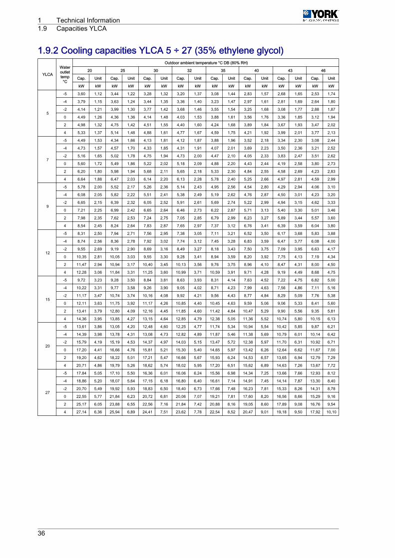
1.9.2 Cooling capacities YLCA 5 ÷ 27 (35% ethylene glycol)
YLCA
Wateroutlettemp°C
Outdoor ambient temperature °C DB (80% RH)
20 25 30 32 35 40 43 46
Cap. Unit Cap. Unit Cap. Unit Cap. Unit Cap. Unit Cap. Unit Cap. Unit Cap. Unit
kW kW kW kW kW kW kW kW kW kW kW kW kW kW kW kW
5
-5 3,60 1,12 3,44 1,22 3,28 1,32 3,20 1,37 3,08 1,44 2,83 1,57 2,68 1,65 2,53 1,74
-4 3,79 1,15 3,63 1,24 3,44 1,35 3,36 1,40 3,23 1,47 2,97 1,61 2,81 1,69 2,64 1,80
-2 4,14 1,21 3,99 1,30 3,77 1,42 3,68 1,46 3,55 1,54 3,25 1,68 3,08 1,77 2,88 1,87
0 4,49 1,26 4,36 1,36 4,14 1,48 4,03 1,53 3,88 1,61 3,56 1,76 3,36 1,85 3,12 1,94
2 4,98 1,32 4,75 1,42 4,51 1,55 4,40 1,60 4,24 1,68 3,89 1,84 3,67 1,93 3,47 2,02
4 5,33 1,37 5,14 1,48 4,88 1,61 4,77 1,67 4,59 1,75 4,21 1,92 3,99 2,01 3,77 2,13
7
-5 4,49 1,53 4,34 1,66 4,13 1,81 4,12 1,87 3,88 1,96 3,52 2,18 3,34 2,30 3,08 2,44
-4 4,73 1,57 4,57 1,70 4,33 1,85 4,31 1,91 4,07 2,01 3,69 2,23 3,50 2,36 3,21 2,52
-2 5,16 1,65 5,02 1,78 4,75 1,94 4,73 2,00 4,47 2,10 4,05 2,33 3,83 2,47 3,51 2,62
0 5,60 1,72 5,49 1,86 5,22 2,02 5,18 2,09 4,88 2,20 4,43 2,44 4,19 2,58 3,80 2,73
2 6,20 1,80 5,98 1,94 5,68 2,11 5,65 2,18 5,33 2,30 4,84 2,55 4,58 2,69 4,23 2,83
4 6,64 1,88 6,47 2,03 6,14 2,20 6,13 2,28 5,78 2,40 5,25 2,66 4,97 2,81 4,59 2,99
9
-5 5,78 2,00 5,52 2,17 5,26 2,36 5,14 2,43 4,95 2,56 4,54 2,80 4,29 2,94 4,06 3,10
-4 6,08 2,05 5,82 2,22 5,51 2,41 5,38 2,49 5,19 2,62 4,76 2,87 4,50 3,01 4,23 3,20
-2 6,65 2,15 6,39 2,32 6,05 2,52 5,91 2,61 5,69 2,74 5,22 2,99 4,94 3,15 4,62 3,33
0 7,21 2,25 6,99 2,42 6,65 2,64 6,46 2,73 6,22 2,87 5,71 3,13 5,40 3,30 5,01 3,46
2 7,98 2,35 7,62 2,53 7,24 2,75 7,05 2,85 6,79 2,99 6,23 3,27 5,89 3,44 5,57 3,60
4 8,54 2,45 8,24 2,64 7,83 2,87 7,65 2,97 7,37 3,12 6,76 3,41 6,39 3,59 6,04 3,80
12
-5 8,31 2,50 7,94 2,71 7,56 2,95 7,38 3,05 7,11 3,21 6,52 3,50 6,17 3,68 5,83 3,88
-4 8,74 2,56 8,36 2,78 7,92 3,02 7,74 3,12 7,45 3,28 6,83 3,59 6,47 3,77 6,08 4,00
-2 9,55 2,69 9,19 2,90 8,69 3,16 8,49 3,27 8,18 3,43 7,50 3,75 7,09 3,95 6,63 4,17
0 10,35 2,81 10,05 3,03 9,55 3,30 9,28 3,41 8,94 3,59 8,20 3,92 7,75 4,13 7,19 4,34
2 11,47 2,94 10,94 3,17 10,40 3,45 10,13 3,56 9,76 3,75 8,96 4,10 8,47 4,31 8,00 4,50
4 12,28 3,06 11,84 3,31 11,25 3,60 10,99 3,71 10,59 3,91 9,71 4,28 9,19 4,49 8,68 4,75
15
-5 9,72 3,23 9,28 3,50 8,84 3,81 8,63 3,93 8,31 4,14 7,63 4,52 7,22 4,75 6,82 5,00
-4 10,22 3,31 9,77 3,58 9,26 3,90 9,05 4,02 8,71 4,23 7,99 4,63 7,56 4,86 7,11 5,16
-2 11,17 3,47 10,74 3,74 10,16 4,08 9,92 4,21 9,56 4,43 8,77 4,84 8,29 5,09 7,76 5,38
0 12,11 3,63 11,75 3,92 11,17 4,26 10,85 4,40 10,45 4,63 9,59 5,06 9,06 5,33 8,41 5,60
2 13,41 3,79 12,80 4,09 12,16 4,45 11,85 4,60 11,42 4,84 10,47 5,29 9,90 5,56 9,35 5,81
4 14,36 3,95 13,85 4,27 13,15 4,64 12,85 4,79 12,38 5,05 11,36 5,52 10,74 5,80 10,15 6,13
20
-5 13,61 3,86 13,05 4,20 12,48 4,60 12,25 4,77 11,74 5,34 10,94 5,54 10,42 5,85 9,87 6,21
-4 14,39 3,98 13,78 4,31 13,08 4,73 12,82 4,89 11,87 5,46 11,38 5,69 10,79 6,01 10,14 6,42
-2 15,79 4,19 15,19 4,53 14,37 4,97 14,03 5,15 13,47 5,72 12,38 5,97 11,70 6,31 10,92 6,71
0 17,20 4,41 16,66 4,76 15,81 5,21 15,30 5,40 14,65 5,97 13,42 6,26 12,64 6,62 11,67 7,00
2 19,20 4,62 18,22 5,01 17,21 5,47 16,66 5,67 15,93 6,24 14,53 6,57 13,65 6,94 12,79 7,29
4 20,71 4,86 19,79 5,26 18,62 5,74 18,02 5,95 17,20 6,51 15,62 6,89 14,63 7,26 13,67 7,72
27
-5 17,84 5,05 17,10 5,50 16,36 6,01 16,06 6,24 15,56 6,98 14,34 7,25 13,66 7,66 12,93 8,12
-4 18,86 5,20 18,07 5,64 17,15 6,18 16,80 6,40 16,61 7,14 14,91 7,45 14,14 7,87 13,30 8,40
-2 20,70 5,49 19,92 5,93 18,83 6,50 18,40 6,73 17,66 7,48 16,23 7,81 15,33 8,26 14,31 8,78
0 22,55 5,77 21,84 6,23 20,72 6,81 20,06 7,07 19,21 7,81 17,60 8,20 16,56 8,66 15,29 9,16
2 25,17 6,05 23,88 6,55 22,56 7,16 21,84 7,42 20,88 8,16 19,05 8,60 17,89 9,08 16,76 9,54
4 27,14 6,36 25,94 6,89 24,41 7,51 23,62 7,78 22,54 8,52 20,47 9,01 19,18 9,50 17,92 10,10
1 Technical Information1.9 Capacities YLCA
36

1.10 Cooling operation and hydraulic diagrams1.10.1 YLCA models: cooling only1 Heat exchange takes place between the heat transfer liquid (water or glycol water) and the coolant
in the plate heat exchanger.2 Water is cooled, and coolant is evaporated and reheated.3 Then the Scroll compressor condenses the coolant (gas) until the condensing pressure is reached,
and the coolant goes to the air cooled condenser unit.4 In the air cooled condenser unit, heat is exchanged between the air and the coolant.5 The air is heated and evacuated from the cooling unit (heat rejection).6 The coolant is condensed and sub-cooled.7 Then the coolant (liquid) goes on to the expansion element where it is expanded until the evaporation
pressure is reached, next it goes to the plate heat exchanger to start a new cooling cycle.
Technical Information 1Cooling operation and hydraulic diagrams 1.10
37

Cooling operation and hydraulic diagram YLCA (only cooling)
b
aD
P
A
P
B
1
8
8
PC
5c
d
4
6
2
3
7
12
11
10
F
E
14
9 13
5
Safety/Control devices ComponentsA High-pressure switch 1 Compressor 11 Expansion vesselB Low pressure switch 2 Air-cooled condenser 12 Drain connectionC Condensing pressure trans‐
ducer (Optional LAK YLCA 5to 15)(Standard YLCA 20, 27)
3 Filter dryer 13 Water filter (to be installed out‐side the unit)
D Battery temperature sensor.(Standard YLCA 5 to 15) 4 Sight glass (YLCA 20, 27) 14 Safety valve
E Water outlet temp. sensor (An‐tifreeze and display) 5 Expansion element → Pipe connection with Schrader
valveF Water inlet temp. sensor (Set‐
ting and display) 6 Plate heat exchanger - ‑ ‑ For units with hydro kit only
7 Flow switch a Water inlet 8 Ball valve (YLCA 27) b Water outlet 9 Water pump c Expansion valve YLCA 20 to 27 10 Automatic air bleed d RESTRICTOR YLCA 5 to 15
1 Technical Information1.10 Cooling operation and hydraulic diagrams
38

1.10.2 YLHA PLUS models: heat pumpCooling cycle1 The 4-way valve is activated.2 Heat exchange takes place between the heat transfer liquid (water or glycol water) and the coolant
in the plate heat exchanger. Water is cooled, and coolant is evaporated and reheated.3 Then the Scroll-type compressor condenses the coolant (gas) until the condensing pressure is
reached, and the coolant goes to the air cooled condenser unit.4 In the air cooled condenser unit, heat is exchanged between the air and the coolant. The air is heated
and evacuated from the cooling unit (heat rejection).5 The coolant is condensed and sub-cooled.6 Then the coolant (liquid) goes on to the expansion element where it is expanded until the evaporation
pressure is reached, next it goes to the plate heat exchanger to start a new cooling cycle.
Heating cycle
The cycle is reversed to heating mode. The 4-way valve is not activated. The condenser unit becomesthe evaporator and the evaporator becomes the condenser. The water in the plate heat exchanger isheated.
Technical Information 1Cooling operation and hydraulic diagrams 1.10
39

Cooling operation and hydraulic diagram YLHA PLUS 5 to 15
b
12
11
5
13
9
10
8
a
7
4
14
E
F
1
3
4
P C
Safety/Control devices ComponentsA High-pressure switch 1 Compressor 10 Liquid receiverB Low pressure switch 2 Air-cooled condenser 11 Drain connectionC Pressure transducer port. 3 Filter dryer 12 Water filter (to be installed
outside the unit)E Condenser unit temp. sensor
(fan speed regulation, defrost,reading)
4 Expansion element 13 Safety valve
F Water outlet temp. sensor (anti‐freeze, regulation and display) 5 Water pump 14 Flow switch
G Water inlet temp. sensor (Set‐ting and display) 6 Plate heat exchanger → Pipe connection with
Schrader valve 7 Automatic air bleed - ‑ ‑ For units with hydro kit only 8 Expansion vessel a Water inlet 9 Four-way valve b Water outlet
1 Technical Information1.10 Cooling operation and hydraulic diagrams
40

Cooling operation and hydraulic diagram YLHA PLUS 20 and 27
12
710
10
8
8 9
11
18
14
13 17
15 16
b
a
1
Safety/Control devices ComponentsA High-pressure switch 1 Compressor 12 Automatic air bleedB Low pressure switch 2 Air-cooled condenser 13 Expansion vesselE Condenser unit temp. sensors
(fan speed regulation and read‐ing)
3 Filter dryer 14 Safety valve
F Water outlet temp. sensor (anti‐freeze, regulation and display) 4 Sight glass 15 Water pump
G Water inlet temp. sensor (Set‐ting and display) 5 Expansion valve 16 Flow switch
6 Heat exchanger 17 Drain connection
7 Heat exchanger antifreeze heat‐er 18 Water filter (outside the unit)
8 Globe valve → Pipe connection with Schrad‐er valve
9 Four-way valve - ‑ ‑ For units with hydro kit only 10 Check valve a Water inlet 11 Liquid receiver b Water outlet
Technical Information 1Cooling operation and hydraulic diagrams 1.10
41

1.11 Instructions for installation and connection of the unit1.11.1 Characteristics of the locationBefore locating the unit, make sure you have received the appropriate product by checking the specifi‐cations described on the outside of same.
The unit should be placed on a perfectly horizontal plane, making sure the base can support the weightof the unit.
If vibration-free operation is required, the unit can be placed on a cork or similar anti-vibratory base, orfastened to the base with anti-vibratory plates or supports.
Location of various units
Avoid recirculation of air between units.OK
NO
1 Technical Information1.11 Instructions for installation and connection of the unit
42
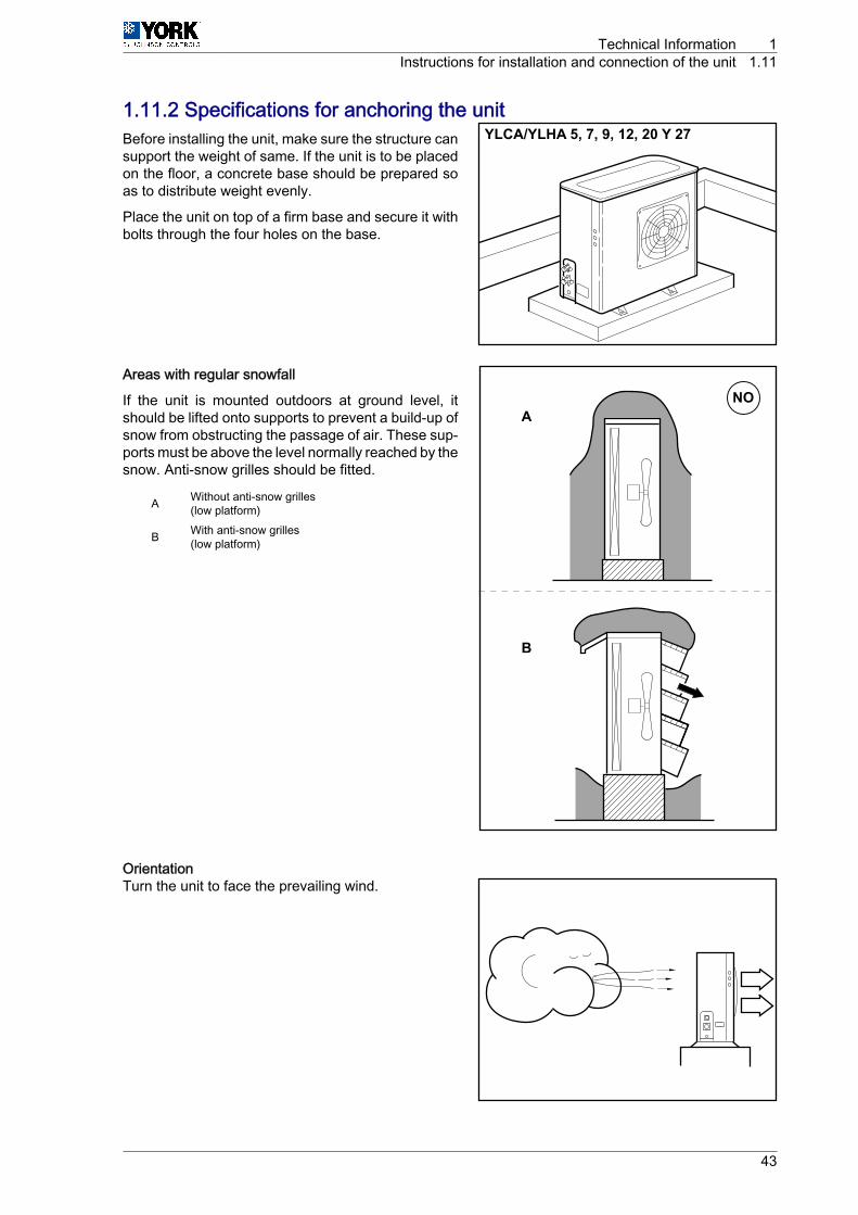
1.11.2 Specifications for anchoring the unitBefore installing the unit, make sure the structure cansupport the weight of same. If the unit is to be placedon the floor, a concrete base should be prepared soas to distribute weight evenly.
Place the unit on top of a firm base and secure it withbolts through the four holes on the base.
Areas with regular snowfall
If the unit is mounted outdoors at ground level, itshould be lifted onto supports to prevent a build-up ofsnow from obstructing the passage of air. These sup‐ports must be above the level normally reached by thesnow. Anti-snow grilles should be fitted.
A Without anti-snow grilles(low platform)
B With anti-snow grilles(low platform)
OrientationTurn the unit to face the prevailing wind.
YLCA/YLHA 5, 7, 9, 12, 20 Y 27
NOA
B
Technical Information 1Instructions for installation and connection of the unit 1.11
43

1.11.3 Hydraulic connectionsThe hydraulic connections of the water inlet and outlet of the unit should be carried out respecting theinlet and outlet directions indicated.
Galvanised iron or copper piping can be used, with dimensions no lower than those indicated, and keep‐ing in mind the pressure drops at said connections and in the internal exchanger of the installation.
Pump dimensioning should be carried out in accordance with a nominal flow rate that allows an Ģt withinthe operating limits.
During the winter season, with outdoor temperatures below 0 °C, take precautions to avoid freezing ofthe water in the pipes.
Usually, a filling solution is applied to the circuit with an antifreeze mixture (glycol).
1.11.4 Rotational direction of Scroll compressorsThe Scroll compressors only operate correctly in one direction of rotation. Although these units are pro‐tected by a phase order detector, when the unit is started, check that the unit rotates in the correctdirection. If it is not correct:
If the compressors are not connected correctly and are rotating in the wrong direction:• The compressor will not compress.• Operating noise will be abnormal.• Electricity consumption (A) will be low.• They overheat.
The phase detector must have both LEDs lit for correct operation:• Green LED lit means: Power ON.• Yellow LED lit means: Relay ON.
1 Technical Information1.11 Instructions for installation and connection of the unit
44

1.11.5 Wiring diagramsElectrical installation YLCA / YLHA PLUS 5 to 27
AB
C
a1
a3
b
c
d
e
f
A YLCA terminal strip bFlow Switch (only inunits without hydraulicgroup)
B Outdoor terminal strip c
General alarm (voltage-free inverter contactmax. 2A resist. A 230Vac)
C Main switch d Remote ON / OFFswitch
a1Supply (200 ‑ 1+ N ‑ ph‑ 50 Hz)(single-phase units)
e
Remote COOL / HEATswitchCLOSED = COOLOPEN = HEAT(YLHA units only)
a3Supply (400 ‑ 3 + N ‑ph ‑ 50 Hz)(three-phase units)
f Auxiliary heater
□ Terminal stripsYLCA / YLHA PLUS ◊ Voltage-free terminal strip contact
YLCA / YLHA PLUSØ Outdoor unit terminals - ‑ ‑ Client's electrical installation○ 230 Vac terminal
C A U T I O NThe cable used for the unit power supply must be H05 RN ‑ F
Technical Information 1Instructions for installation and connection of the unit 1.11
45

1.12 Unit sound power spectrum dataYLCA-YLHA Plus models
YLCA-YLHA Plus modelsFrequency (Hz) 5 7 9 12 15 20 27
125 Hz 66,2 66,2 74 79,6 79,6 77 75,6250 Hz 70,5 70,5 72,3 74,3 74,3 72,4 81,3500 Hz 67,7 67,7 67,9 70,2 70,2 72,9 75,91000 Hz 65,7 65,7 66,1 67,5 67,5 69,1 70,82000 Hz 60,2 60,2 61,8 62,7 62,7 63,9 68,64000 Hz 55,1 55,1 56,3 57,7 57,7 58,2 63,38000 Hz 48,8 48,8 52,3 51 51 52,5 55,7Sound power level dB (A) 70 70 71 73 73 74 78
The data given in this table are sound power values in accordance with ISO EN3743.
1 Technical Information1.12 Unit sound power spectrum data
46

1.13 Operating instructions1.13.1 Operating instructions µC2DESCRIPTION OF THE CONTROL UNIT
This is a multipurpose controller specially programmed for use with air-water cooling units and heatpumps equipped with a compressor with one single power stage.
Main functions• Water temperature control (at inlet or outlet, As per parameter r6).• Defrost cycle management.• System operating and safety management.• Fan speed control.• Alarm management.• Connection for supervision and remote assistance (serial connection accessory RS485).
Devices controlled• Compressor• Fans• Four-way valve• Water pump• Alarm device• Auxiliary heater
STANDARD COMPONENTSControl module
This is the central nucleus that processes the signals coming from the probes and protection elementsof the entire system to control its active elements: compressor and fans, four-way valve, water circulatingpump, alarm relay and auxiliary heater. Power supply 24 Vac.
It can also be used for access and control of the system by means of the display, buttons and LEDsavailable. It allows for selection of cool, heat and off functions. Operating parameters can also be modi‐fied, and the system can also be supervised.
Fan speed control module
Operates by phase cut-off. Includes fuse
NTC and ratiometric (pressure) probes
YLCA / YLHA PLUS 5 to 15 standard
4 NTC probes are used to read the temperatures of the system:• B1. Controls the set point. Reads water temperature at exchanger inlet.• B2. Antifreeze control. Reads water temperature at exchanger outlet.• B3. Controls the dynamic set point. Reads outdoor air temperature.• B4. Fan speed and defrost cycle control. Reads coolant pressure inside the battery.
YLHA PLUS, YLCA 20, 27 and YLCA 5 to 15 LAK (Low ambient Kit accessory)
3 NTC probes are used to read system temperatures and a ratiometric pressure transducer (B4) to readcoolant pressure inside the coil:• B1. Controls the set point. Reads water temperature at exchanger inlet.• B2. Antifreeze control. Reads water temperature at exchanger outlet.• B3. Controls the dynamic set point. Reads outdoor air temperature.• B4. Fan speed and defrost cycle control. Reads coolant pressure inside the coil.
Parameters
The set of parameters that configure the operating program of the unit is divided into four levels (Factory,Super User, User and Direct), depending on the function of each parameter and the user’s access level.The parameters of each level can be modified from that same level, as well as lower level parameters.
Technical Information 1Operating instructions 1.13
47

Factory Level
Accessible with the Factory password. Allows configuration of all unit parameters.
Super User Level
Accessible with the Super User password. Allows setting of Super User, User and Direct parameters.
User Level
Accessible with password 22. Allows access to all parameters the user normally sets.
Direct Level
Accessible without a password. Allows for reading of the values detected by the probes, as well as othersystem values. Can be used by the user without affecting unit operation.
General
Modification of the parameters that affect basic unit configuration should be made with the controller inStandby position.
1 Technical Information1.13 Operating instructions
48

General diagramGeneral diagram YLCA 5 ÷ 15
A B C D
F
GH
*1
J I
E
A Four-way valve B2 Water outlet temperature probe (Antifreeze pro‐tection)
B Pump B3Outdoor temperature probe in units with LAK
Battery probe in standard units (fan and defrostcontrol)
C Heater B4 Outdoor probe standard units (Dynamic Set point)
D Compressor 1 ID1 Water flow switch
E Alarm ID2 Remote COOL / HEAT
F 230 / 24 transformer ID3 High pressure switch
G Fan speed control ID4 Low pressure switch
H Communication ID5 Remote ON / OFF
I Programmable key N Neutral
J Outdoor probe standard units L Phase
B1 Water inlet temperature probe (Control set point)
(*1): When the low ambient kit (LAK) is fitted, set the B4 probe as a pressure transducer and the B3probe as an outdoor temperature NTC probe.
Technical Information 1Operating instructions 1.13
49

General diagram YLCA 20 ÷ 27 and YLHA 5 ÷ 27
A B C D
F
GH
I
E
A Four-way valve B2 Water outlet temperature probe (Antifreeze pro‐tection)
B Pump B3 Outdoor temperature probe (Dynamic set point)
C Heater B4 Ratiometric pressure probe (fan speed and defrostcontrol)
D Compressor 1 ID1 Water flow switch
E Alarm ID2 Remote COOL / HEAT
F 230 / 24 transformer ID3 High pressure switch
G Fan speed control ID4 Low pressure switch
H Communication ID5 Remote ON / OFF
I Programmable key N Neutral
B1 Water inlet temperature probe (Control set point) L Phase
1 Technical Information1.13 Operating instructions
50
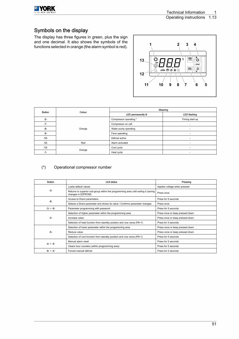
Symbols on the displayThe display has three figures in green, plus the signand one decimal. It also shows the symbols of thefunctions selected in orange (the alarm symbol is red).
Button ColourMeaning
LED permanently lit LED flashing
-2-
Orange
Compressor operating * Timing start-up
-7- Compressor on call -
-8- Water pump operating -
-9- Fans operating -
-10- Defrost active -
-12- Red Alarm activated -
-13-Orange
Cool cycle -
-1- Heat cycle -
(*) Operational compressor number
Button Unit status Pressing
-3-Loads default values Applies voltage when pressed
Returns to superior sub-group within the programming area until exiting it (savingchanges in E2PROM) Press once
-6-Access to Direct parameters Press for 5 seconds
Selects a Direct parameter and shows its value / Confirms parameter changes Press once
-3- + ‑6- Parameter programming with password Press for 5 seconds
-4-
Selection of higher parameter within the programming area Press once or keep pressed down
Increase value Press once or keep pressed down
Selection of heat function from standby position and vice versa (P6=1) Press for 5 seconds
-5-
Selection of lower parameter within the programming area Press once or keep pressed down
Reduce value Press once or keep pressed down
Selection of cool function from standby position and vice versa (P6=1) Press for 5 seconds
-4- + ‑5-Manual alarm reset Press for 5 seconds
Clears hour counters (within programming area) Press for 5 seconds
-6- + ‑4- Forced manual defrost Press for 5 seconds
1 2 3 4
567891011
1112
13
Technical Information 1Operating instructions 1.13
51

Control layoutA Outdoor temperature
probe:YLCA / YLHA PLUS 5to 15 with LAK (B3)YLCA / YLHA PLUS 5to 15 standard (B4)YLCA / YLHA PLUS20 to 27 standard(B3)
H Low pressure switch (LP)
B Fan I CompressorC Flow switch (FS) J High pressure switch
(HP)D NTC water outlet
probe (B2)K Four-way valve
E Indoor heat exchang‐er
L Outdoor heat exchanger
F NTC water inlet probe(B1)
M Pressure sensor (BA)(YLCA / YLHA PLUS 5 to20 LAK)(YLCA / YLHA PLUS 20to 27)
G Pump N Outdoor exchanger NTCprobe (B3)(YLCA / YLHA PLUS 5 to15)
Parameter tablesThe following tables show the parameters and their values, divided into groups:
Parameter level codes Supervision variablesD Direct R/W Read/write parameterU User R Read-only parameterS Super user
F Factory
C
D
E
F
G
K
J HI
M NL
A
B
1 Technical Information1.13 Operating instructions
52
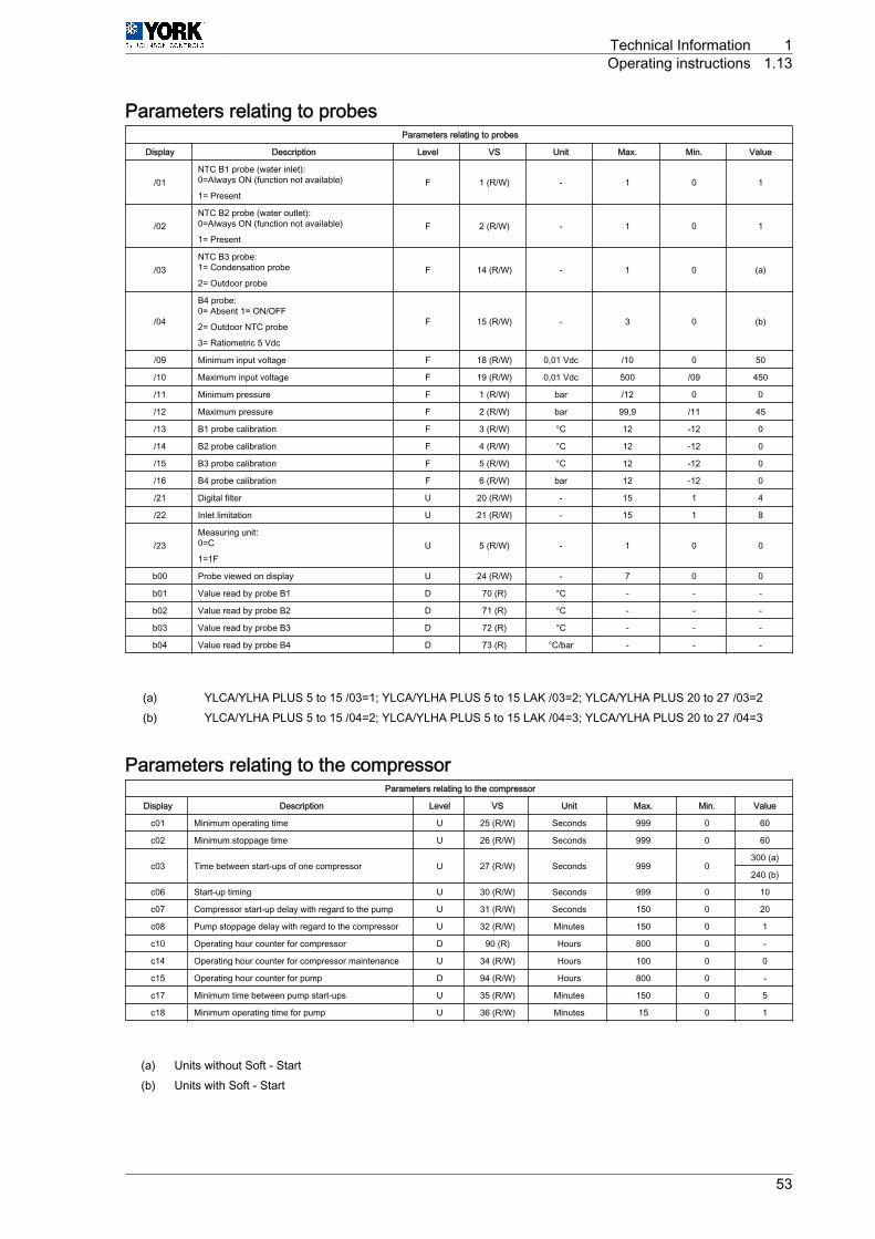
Parameters relating to probesParameters relating to probes
Display Description Level VS Unit Max. Min. Value
/01NTC B1 probe (water inlet):0=Always ON (function not available)
1= PresentF 1 (R/W) - 1 0 1
/02NTC B2 probe (water outlet):0=Always ON (function not available)
1= PresentF 2 (R/W) - 1 0 1
/03NTC B3 probe:1= Condensation probe
2= Outdoor probeF 14 (R/W) - 1 0 (a)
/04
B4 probe:0= Absent 1= ON/OFF
2= Outdoor NTC probe
3= Ratiometric 5 Vdc
F 15 (R/W) - 3 0 (b)
/09 Minimum input voltage F 18 (R/W) 0,01 Vdc /10 0 50
/10 Maximum input voltage F 19 (R/W) 0,01 Vdc 500 /09 450
/11 Minimum pressure F 1 (R/W) bar /12 0 0
/12 Maximum pressure F 2 (R/W) bar 99,9 /11 45
/13 B1 probe calibration F 3 (R/W) °C 12 -12 0
/14 B2 probe calibration F 4 (R/W) °C 12 -12 0
/15 B3 probe calibration F 5 (R/W) °C 12 -12 0
/16 B4 probe calibration F 6 (R/W) bar 12 -12 0
/21 Digital filter U 20 (R/W) - 15 1 4
/22 Inlet limitation U 21 (R/W) - 15 1 8
/23Measuring unit:0=C
1=1FU 5 (R/W) - 1 0 0
b00 Probe viewed on display U 24 (R/W) - 7 0 0
b01 Value read by probe B1 D 70 (R) °C - - -
b02 Value read by probe B2 D 71 (R) °C - - -
b03 Value read by probe B3 D 72 (R) °C - - -
b04 Value read by probe B4 D 73 (R) °C/bar - - -
(a) YLCA/YLHA PLUS 5 to 15 /03=1; YLCA/YLHA PLUS 5 to 15 LAK /03=2; YLCA/YLHA PLUS 20 to 27 /03=2(b) YLCA/YLHA PLUS 5 to 15 /04=2; YLCA/YLHA PLUS 5 to 15 LAK /04=3; YLCA/YLHA PLUS 20 to 27 /04=3
Parameters relating to the compressorParameters relating to the compressor
Display Description Level VS Unit Max. Min. Value
c01 Minimum operating time U 25 (R/W) Seconds 999 0 60
c02 Minimum stoppage time U 26 (R/W) Seconds 999 0 60
c03 Time between start-ups of one compressor U 27 (R/W) Seconds 999 0300 (a)
240 (b)
c06 Start-up timing U 30 (R/W) Seconds 999 0 10
c07 Compressor start-up delay with regard to the pump U 31 (R/W) Seconds 150 0 20
c08 Pump stoppage delay with regard to the compressor U 32 (R/W) Minutes 150 0 1
c10 Operating hour counter for compressor D 90 (R) Hours 800 0 -
c14 Operating hour counter for compressor maintenance U 34 (R/W) Hours 100 0 0
c15 Operating hour counter for pump D 94 (R/W) Hours 800 0 -
c17 Minimum time between pump start-ups U 35 (R/W) Minutes 150 0 5
c18 Minimum operating time for pump U 36 (R/W) Minutes 15 0 1
(a) Units without Soft ‑ Start(b) Units with Soft ‑ Start
Technical Information 1Operating instructions 1.13
53
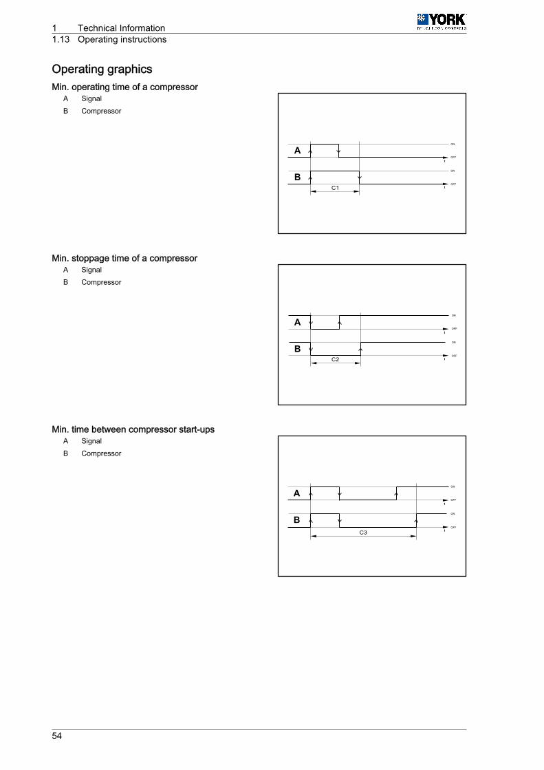
Operating graphicsMin. operating time of a compressor
A SignalB Compressor
Min. stoppage time of a compressorA SignalB Compressor
Min. time between compressor start-upsA SignalB Compressor
B
A
C1
B
A
C2
C3
B
A
1 Technical Information1.13 Operating instructions
54

Compressor / pump stoppage delaysA CompressorB Pump
Pump / compressor start-up delaysA PumpB Compressor
C8B
A
C7
B
A
Technical Information 1Operating instructions 1.13
55

Parameters relating to fansParameters relating to fans
Display Description Level VS Unit Max. Min. Value
F01Fan outlet:0= Absent (function not available
1= PresentF 10 (R/W) 1 0 1
F02
Operating mode:0=Always ON (function not available)
1= parallel to the compressor (function notavailable)
2=ON/OFF operation (function not availa‐ble)
3= parallel to the compressor and speedadjustment
U 48 (R/W) 3 0 3
F03 Minimum Triac voltage F 49 (R/W) step F04 0 35
F04 Maximum Triac voltage F 50 (R/W) step 100 F03 85
F05Minimum speed temp, cool cycle
F 24 (R/W)°C
80 -4030
Minimum speed pressure, cool cycle (1) bar 22,2
F06
Maximum speed temp differential, cool cy‐cle
F 26 (R/W)°C
50 015
Maximum speed pressure differential, coolcycle (1) bar 3,7
F07Fan stoppage temp differential, cool cycle
F 28 (R/W)°C
50 010
Fan stoppage pressure differential, cool cy‐cle (1) bar 6,5
F08 Minimum speed temp, heat cycle F 30 (R/W) °C 80 -40 6
F09 Maximum speed differential, heat cycle F 32 (R/W) °C 50 0 3
F10 Fan stoppage temp differential, heat cycle F 34 (R/W) °C F08 0 6
F11 Fan start-up time F 51 (R/W) Seconds 120 0 10
F12 Triac impulse duration F 52 (R/W) Seconds 10 0 2
F13
Fan management in defrost mode:0= fan disabled
1= fan enabled in cool cycle mode (functionnot available).
2= fan disabled until the defrost end tem‐perature is reached and with top-speedstart-up during d16
F 53 (R/W) 2 0 2
F14 Fan operating when starting with high am‐bient temperature U 91 (R/W) Seconds 999 0 30
(1) Parameters to be checked when pressure probes are to be used (low ambient accessory) YLCA 5 to 15.
A Fan speedB Condensing temperatureC Evaporation temperature
A
A
C
B
1 Technical Information1.13 Operating instructions
56

Parameters relating to defrostParameters relating to defrost
Parameters Description Level VS Unit Max. Min. Value
d01Defrost operation:0= Absent (function not available
1= PresentU 7 (R/W) - 1 0 1
d02Defrost at time or temperature:0= Time (function not available)
1= Temperature / PressureU 8 (R/W) - 1 0 1
d03Defrost start temp
U 19 (R/W)°C
d04-40/ -3
Defrost start pressure bar 11 6,2
d04Defrost end temp
U 21 (R/W)°C 80/
d0320
Defrost end pressure bar 12 14,4
d05 Minimum defrost start time U 37 (R/W) Seconds 150 10 10
d06 Minimum defrost duration U 38 (R/W) Seconds 150 0 0
d07 Maximum defrost duration U 39 (R/W) Minutes 15 1 6
d08 Time between two defrost cycles U 40 (R/W) Minutes 150 10 30
d11Activation of heaters during defrost:0= No
1= YesU 9 (R/W) - 0 1 1
d12 Compressor stoppage before defrost F 43 (R/W) Minutes 3 0 1
d13 Compressor stoppage after defrost F 44 (R/W) Minutes 3 0 1
d16 Forced ventilation time at defrost end (if F13=2only) F 47 (R/W) Seconds 360 0 60
A Defrost end temperature(d04) E Minimum defrost start
time (d05)B Defrost start F Timer start
C Defrost end G Defrost start tempera‐ture (d03)
D Maximum defrost dura‐tion (d06)
AB
C
DE
F
G
Technical Information 1Operating instructions 1.13
57

Antifreeze control configuration parametersAntifreeze control configuration parameters
Parameters Description Level VS Unit Max. Min. Value
A01 Antifreeze control set point temperature U 11 (R/W) °C - A07 3
A02 Antifreeze reset differential U 12 (R/W) °K 50 0,3 5
A03 Antifreeze alarm by-pass time U 22 (R/W) Seconds 150 0 0
A04 Antifreeze heater activation temperature U 13 (R/W) °C r16 A01 3
A05 Antifreeze heater activation differential U 14 (R/W) °K 50 0,3 2
A06Backup heater control probe:0= Control probe
1= Antifreeze probeF 6 (R/W) - 1 0 0
A07 Minimum level antifreeze control set pointtemperature U 15 (R/W) °C 79 -40 3
A08 Heating heater activation set point tempera‐ture U 16 (R/W) °C r15 A01 3
A09 Heating heater deactivation set point temper‐ature differential U 17 (R/W) °C 50 0,3 3
A10
Automatic start-up by antifreeze alarm (unit inStandby):
0= Function disabled
1= Water pump + heater
2= Water pump + heater + compressor (heatpumps only)
3= Heater
U 23 (R/W) 3 0 2
A Antifreeze reset dif‐ferential (A2) D Antifreeze alarm
BAntifreeze heater ac‐tivation differential(A5)
E Antifreeze heater activa‐tion temperature (A4)
C Heaters F Antifreeze set point tem‐perature (A1)
A B
C
Dt
EF
1 Technical Information1.13 Operating instructions
58

Unit configuration parametersUnit configuration parameters
Display Description Level VS Unit Max. Min. Value
H01Unit model:2= Water cooling unit
3= Air-water heat pumpF 54 (R/W)
2(YLCA)
3(YLHA PLUS)
H02 Number of ventilation circuits (do not modify this pa‐rameter) F 12 (R/W) 0
H03 No. of evaporating units present (do not modify thisparameter) F 13 (R/W) 0
H04 No. of compressors per circuit (do not modify this pa‐rameter) F 55 (R/W) 0
H05
Pump operation:0= Absent
1= Always ON
2= ON upon controller call
3= ON upon controller and time call
F 56 (R/W) 3 0 1
H06COOL/HEAT digital input:0= Absent
1= PresentU 14 (R/W) 1 0 0
H07ON/OFF digital input:0= Absent
1= PresentU 15 (R/W) 1 0 0
H08 Network configuration (do not modify this parameter). F 57 (R/W) 3 0 0
H09Keyboard locked:0= Disabled
1= EnabledU 16 (R/W) 1 0 1
H10 Serial direction for monitoring:0= Future use as terminal U 58 (R/W) 200 1 1
H11 Output configuration (not selectable) F 59 (R/W) 3 0 0
H12 4-way valve logic operation. Activated in cold cycle (donot modify this parameter) F 60 (R/W) 3 0 0
H21 Second pump function (do not modify this parameter) F 62 (R/W) 4 0 0
H22Default parameter loading disabled:0= Disabled
1= EnabledF 18 (R/W) 1 0 1
H23Modbus protocol setting:0= Disabled
1= EnabledF 11 1 0 0
Technical Information 1Operating instructions 1.13
59
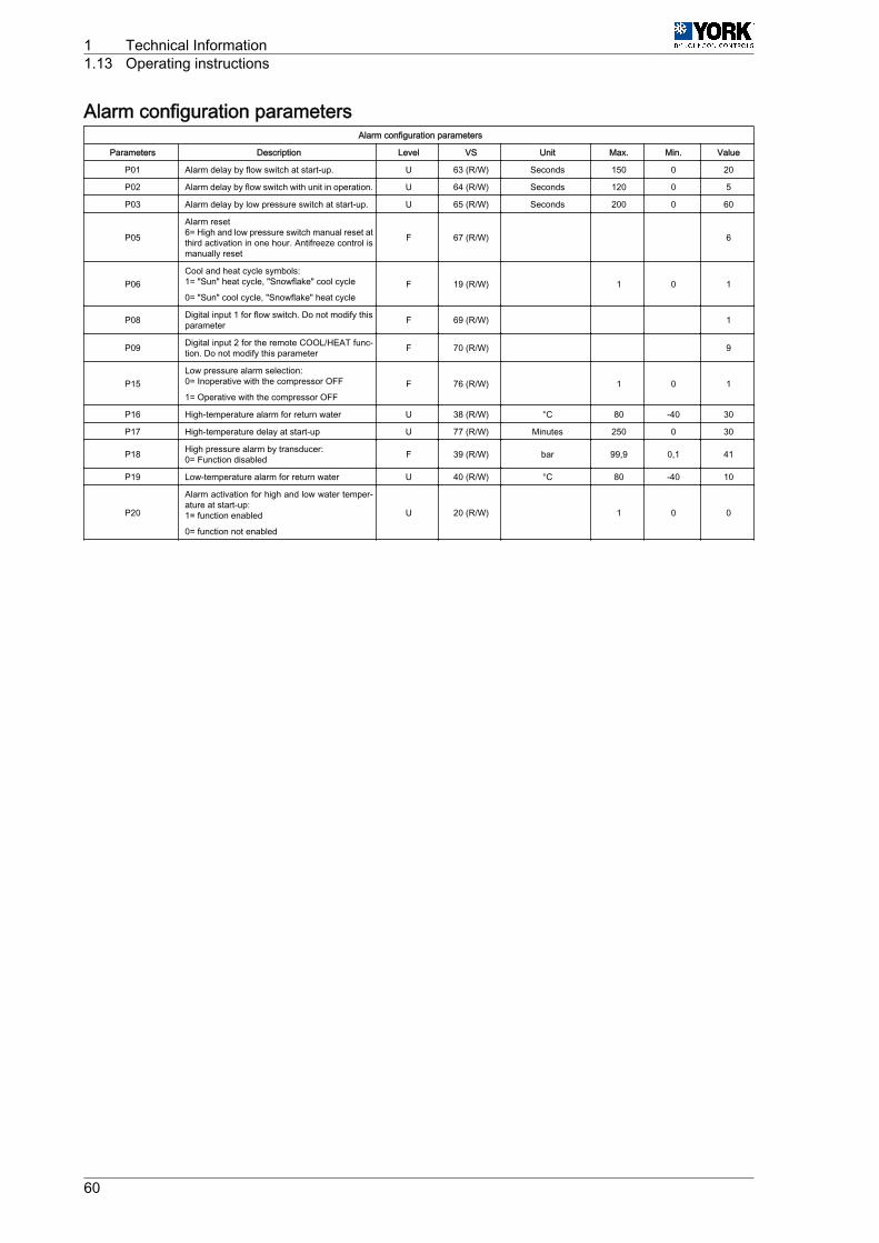
Alarm configuration parametersAlarm configuration parameters
Parameters Description Level VS Unit Max. Min. Value
P01 Alarm delay by flow switch at start-up. U 63 (R/W) Seconds 150 0 20
P02 Alarm delay by flow switch with unit in operation. U 64 (R/W) Seconds 120 0 5
P03 Alarm delay by low pressure switch at start-up. U 65 (R/W) Seconds 200 0 60
P05
Alarm reset6= High and low pressure switch manual reset atthird activation in one hour. Antifreeze control ismanually reset
F 67 (R/W) 6
P06Cool and heat cycle symbols:1= "Sun" heat cycle, "Snowflake" cool cycle
0= "Sun" cool cycle, "Snowflake" heat cycleF 19 (R/W) 1 0 1
P08 Digital input 1 for flow switch. Do not modify thisparameter F 69 (R/W) 1
P09 Digital input 2 for the remote COOL/HEAT func‐tion. Do not modify this parameter F 70 (R/W) 9
P15Low pressure alarm selection:0= Inoperative with the compressor OFF
1= Operative with the compressor OFFF 76 (R/W) 1 0 1
P16 High-temperature alarm for return water U 38 (R/W) °C 80 -40 30
P17 High-temperature delay at start-up U 77 (R/W) Minutes 250 0 30
P18 High pressure alarm by transducer:0= Function disabled F 39 (R/W) bar 99,9 0,1 41
P19 Low-temperature alarm for return water U 40 (R/W) °C 80 -40 10
P20
Alarm activation for high and low water temper‐ature at start-up:1= function enabled
0= function not enabled
U 20 (R/W) 1 0 0
1 Technical Information1.13 Operating instructions
60

Controller configuration parametersController configuration parameters
Display Description Level VS Unit Max. Min. Value
r01 Cool cycle set point temperature U 41 (R/W) °C r14 r13 12
r02 Cool set point temperature differential U 42 (R/W) °C 50 0,3 1
r03 Heat cycle set point temperature U 43 (R/W) °C r16 r15 40
r04 Heat cycle set point temperature differential U 44 (R/W) °C 50 0,3 2
r06
Type of regulation:0= Proportional.Temperature
inlet.
1= Proportional + neutral zone. Inlet temp.
2= Proportional. Outlet temperature
3= Proportional + neutral zone. Outlet temp.
4= By time + dead zone. Outlet temperature (coolingunits only)
F 79 (R/W) 4 0 0
r07 Neutral zone differential F 45 (R/W) °C 50 0 1
r08 (Only if r06=4) Maximum activation time. Outlet tem‐perature. F 80 (R/W) Seconds 999 r09 120
r09 (Only if r06=4) Minimum activation time. Outlet temper‐ature. F 81 (R/W) Seconds 999 c04 100
r10 (Only if r06=4) Maximum deactivation time. Outlet tem‐perature. F 82 (R/W) Seconds 999 r11 120
r11 (Only if r06=4) Minimum deactivation time. Outlet tem‐perature. F 83 (R/W) Seconds 999 c05 100
r12 (Only if r06=4) Compressor deactivation differential. F 46 (R/W) °C 50 0 1
r13 Cool cycle minimum set point temperature U 47 (R/W) °C r14 -40 6
r14 Cool cycle maximum set point temperature U 48 (R/W) °C 80 r13 20
r15 Heat cycle minimum set point temperature U 49 (R/W) °C r16 -40 25
r16 Heat cycle maximum set point temperature U 50 (R/W) °C 80 r15 45
r17 Summer offset constant U 51 (R/W) - 5 -5 -0,4
r18 Maximum set point distance U 52 (R/W) °K 20 0,3 3,2
r19 Summer offset start temperature U 53 (R/W) °C 176 -40 32
r20 Winter offset start temperature U 54 (R/W) °C 176 -40 5
r27
Inertia tank suppression.0= No suppression.
1=Suppression in cold cycle
2=Suppression in heat cycle.
3= Always suppressed.
F 88 (R/W) 3 0 3
r28 Minimum low pressure determining time F 89 (R/W) Seconds 999 0 210
r29 Cool cycle low pressure differential F 58 (R/W) °C 50 0,3 3
r30 Heat cycle low pressure differential F 58 (R/W) °C 50 0,3 4
r31 Winter offset constant U 60 (R/W) - 5 -5 -0,4
A Temperature D HEAT set point (r03) + Dif‐ferential (r04)
B Compressor E COOL set point (r01)
C HEAT set point (r03) F COOL set point (r01) + Dif‐ferential (r02)
A
A
B
B
C D
E F
B
B
A
A
Technical Information 1Operating instructions 1.13
61
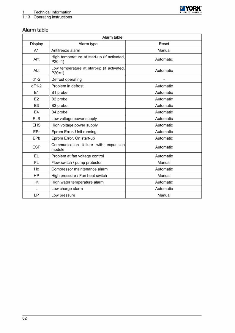
Alarm tableAlarm table
Display Alarm type ResetA1 Antifreeze alarm Manual
Aht High temperature at start-up (if activated,P20=1) Automatic
ALt Low temperature at start-up (if activated,P20=1) Automatic
d1-2 Defrost operating -dF1-2 Problem in defrost Automatic
E1 B1 probe AutomaticE2 B2 probe AutomaticE3 B3 probe AutomaticE4 B4 probe Automatic
ELS Low voltage power supply AutomaticEHS High voltage power supply AutomaticEPr Eprom Error. Unit running. AutomaticEPb Eprom Error. On start-up Automatic
ESP Communication failure with expansionmodule Automatic
EL Problem at fan voltage control AutomaticFL Flow switch / pump protector ManualHc Compressor maintenance alarm AutomaticHP High pressure / Fan heat switch ManualHt High water temperature alarm AutomaticL Low charge alarm Automatic
LP Low pressure Manual
1 Technical Information1.13 Operating instructions
62

Temperature / resistance characteristics of NTC control probes (10 kOhms)Temperature
[°C]Resistance
[kOhms]Temperature
[°C]Resistance
[kOhms]Temperature
[°C]Resistance
[kOhms]Temperature
[°C]Resistance
[kOhms]Temperature
[°C]Resistance
[kOhms]
-50 329,2 -16 55,95 18 13,08 52 3,8 86 1,41
-49 310,7 -15 53,99 19 12,58 53 3,77 87 1,37
-48 293,3 -14 50,9 20 12,09 54 3,65 88 1,33
-47 277 -13 48,66 21 11,83 55 3,53 89 1,3
-46 261,8 -12 46,48 22 11,2 56 3,42 90 1,26
-45 247,5 -11 44,41 23 10,78 57 3,31 91 1,23
-44 234,1 -10 42,45 24 10,38 58 3,21 92 1,2
-43 221,8 -9 40,56 25 10 59 3,11 93 1,16
-42 209,8 -8 38,76 26 9,63 60 3,02 94 1,13
-41 198,7 -7 37,05 27 9,28 61 2,92 95 1,1
-40 188,4 -6 35,48 28 8,94 62 2,83 96 1,06
-39 178,3 -5 33,89 29 8,82 63 2,75 97 1,05
-38 168,9 -4 32,43 30 8,31 64 2,66 98 1,02
-37 160,1 -3 31,04 31 6,01 65 2,58 99 0,99
-36 151,8 -2 29,72 32 7,72 66 2,51 100 0,97
-35 144 -1 28,47 33 7,45 67 2,43 101 0,94
-34 136,6 0 27,28 34 7,19 68 2,36 102 0,92
-33 129,7 1 26,13 35 6,94 69 2,29 103 0,9
-32 123,2 2 25,03 36 6,69 70 2,22 104 0,87
-31 117,1 3 23,09 37 6,46 71 2,16 105 0,85
-30 111,3 4 22,09 38 6,24 72 2,1 106 0,83
-29 106,7 5 22,05 39 6,03 73 2,04 107 0,81
-28 100,4 6 21,15 40 5,82 74 1,98 108 0,79
-27 95,47 7 20,2 41 5,63 75 1,92 109 0,77
-26 90,8 8 19,48 42 5,43 76 1,87
-25 86,39 9 18,7 43 5,24 77 1,81
-24 82,22 10 17,98 44 5,08 78 1,76
-23 78,29 11 17,24 45 4,91 79 1,71
-22 74,58 12 16,55 46 4,74 80 1,66
-21 71,07 13 15,9 47 4,59 81 1,62
-20 67,74 14 15,28 48 4,44 82 1,57
-19 64,54 15 14,68 49 4,3 83 1,53
-18 61,62 16 14,12 50 4,16 84 1,49
-17 58,66 17 13,57 51 4,02 85 1,45
Technical Information 1Operating instructions 1.13
63

FunctionsAlarm reset
Pressing the UP ‑4- and DOWN ‑5- keys for 5 seconds cancels the alarms present in the memory. Atthe same time, the alarm message disappears from the display and the alarm relay is deactivated.
Forced defrost (heat pumps)
Pressing the SEL ‑6- and UP ‑4- keys simultaneously for 5 seconds activates forced defrost of the unit.
Clearing hour countersWhile reading compressor or pump (c10 and c15) op‐erating hours, said counters can be cleared by press‐ing the UP ‑4- and DOWN ‑5- keys simultaneously.
Pump operation4 operating modes can be selected in accordance with the value given to parameter H5.• H5=0 (pump disabled).• H5= 1 (pump always on),• H5= 2 (pump running under control of regulator or in parallel with the compressor),• H5= 3 (pump stops and starts at regular intervals irrespective of the compressor operation (param‐
eters c17 and c18).
Calibration of probes
If necessary, probes can be calibrated by using parameters /13, /14, /15 y /16. See TableParametersrelating to probes, see on page 53.
Remote ON/OFF
A remote ON/OFF inlet can be connected between terminals D5 and B on the connecting strip. To activatesaid inlet, a value of 1 should be given to parameter H07 (H07= 1). With this inlet open the unit is OFF;when closed, the unit is ON. This option does not disable the ON/OFF function of the keyboard.
Remote COOL/HEAT
A remote COOL/HEAT inlet can be connected between terminals D2 and B on the connecting strip. Toactivate said inlet, a value of 1 should be given to parameter H06 (H06= 1). With this inlet open the unitis in HEAT; when closed, the unit is in COOL. This function disables the COOL/HEAT function of thekeyboard.
1 2 3 4
567891011
1112
13
1 Technical Information1.13 Operating instructions
64

2
Electric circuit diagrams
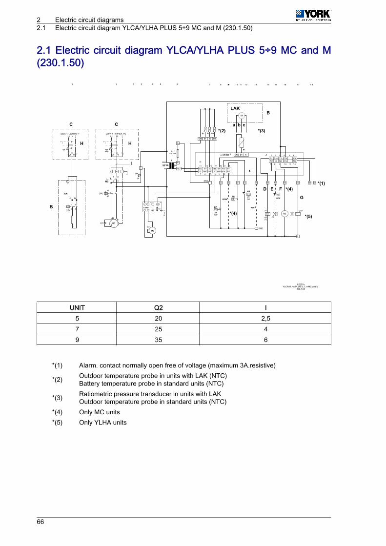
2.1 Electric circuit diagram YLCA/YLHA PLUS 5÷9 MC and M(230.1.50)
I-2531hYLCA/YLHA PLUS 5, 7, 9 MC and M
230.1.50
L1
L1 N
N
Q2Amp
230V, 1 ~,50Hz,N, PE
L1
R
L1
L1 N
N
Q1
230V, 1 ~,50Hz,N,
K2
(15)
AH
2
1
4
3
N
M1
K1(14)
C
S
A1
A2
C1
MS
1
C2
M2
F1
F1
F1315 mA
GO
GNDD4 D2 D1 D3 D5
GND
N1 C1/2 C5N2
C1/2 C3/4N3 N4 N5C3/4
1 2 3 4 5 6
7 8 9 10 1 1 1 2
A1
A2(1)
N1 N4N3 N5 C5
GOG
B1GND
B2GND
B3Y
ID5GND
ID3ID4
ID1ID2
B1 B2 B3
B1 B2 B3
GND
B4 V+GND
B4
J1
10 9 8
7 5 4 3 2 1
11121314
6
J2
4 5 6 7 8 999 1 0 11 1 2 13 14 15 16 17 1 8
L1 N
1 2 30
2
1
4
3
B4
Q3
3A
FSCLOAD
F2
L N Y GND
T230V
0V
20 VA
FSPHP
41bar
R00
RCH
K1 M3V4V
2
chiller 2
PLP
2,5bar
A
24
(0)
N2
HTP
K2
C
B
B
*(3)
*(4)
*(4)
*(5)
*(1)
G
D E F
*(2)C
LAK
a b c
HH
I
UNIT Q2 I5 20 2,57 25 49 35 6
*(1) Alarm. contact normally open free of voltage (maximum 3A.resistive)
*(2) Outdoor temperature probe in units with LAK (NTC)Battery temperature probe in standard units (NTC)
*(3) Ratiometric pressure transducer in units with LAKOutdoor temperature probe in standard units (NTC)
*(4) Only MC units*(5) Only YLHA units
2 Electric circuit diagrams2.1 Electric circuit diagram YLCA/YLHA PLUS 5÷9 MC and M (230.1.50)
66

a Green wire FS Water flow switch (MC units)
b White wire FSC Fan speed controller
c Black wire HTP Heater thermal protection
A Electronic control HP High-pressure switch (41 bar)
B The components in the box are standard acces‐sories supplied by the manufacturer K1 Compressor contactor
C The components in the box are not supplied bythe manufacturer K2 Auxiliary heater contactor
D, M1 Compressor LAK Presostatic Low Ambient Kit accessory
E, AH Auxiliary heater LP Low pressure switch (2,5 bar)
F, M3 Pump (MC units) L1 Line phase
H Install on site M2 Fan motor
I “B” mm2 Cu MS Main switch
AH Auxiliary heater N Neutral
B1 Water inlet temperature probe (NTC) Q1 Thermal magnetic protector
B2 Water outlet temperature probe (NTC) Q2 General / compressor thermal magnetic protec‐tor
B3 Temperature probe *(2) Q3 General thermal magnetic protector, 230V / fan /pump / crankcase heater
B4 *(3) R00 Remote ON / OFF switch
C1 Compressor condenser RCH Remote COOL / HEAT switch
C2 Fan condenser T Transformer 230 / 24V 20 VA
F1 Electronic control protection fuse / 24 V [315 mASLOW] switching V4V, G 4-way valves (on YLHA only)
F2 Fan speed controller fuse
Electric circuit diagrams 2Electric circuit diagram YLCA/YLHA PLUS 5÷9 MC and M (230.1.50) 2.1
67

2.2 Electric circuit diagram YLCA/YLHA PLUS 12 MC and M(230.1.50)
C
B
B
*(3)
*(4)
*(4)
*(5)
I-2584c
*(1)
G
D E
F
*(2)
CLAK
a b c
I
L1
L1 N
N
40Amp
230V, 1 ~,50Hz,N, PEL1
L1 N
N
Q1
230V, 1 ~,50Hz,N,
K2
(15)
AH
2
1
4
3
2
1
4
3
L1 N
HH
K2(14)
*(1) Alarm. Contact normally open free of voltage (maximum 3A.resistive)
*(2) Outdoor temperature probe in units with LAK (NTC)Battery temperature probe in standard units (NTC)
*(3) Ratiometric pressure transducer in units with LAKOutdoor temperature probe in standard units (NTC)
*(4) Only MC units*(5) Only YLHA units
2 Electric circuit diagrams2.2 Electric circuit diagram YLCA/YLHA PLUS 12 MC and M (230.1.50)
68
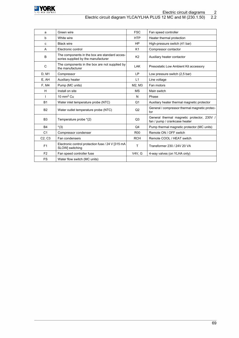
a Green wire FSC Fan speed controller
b White wire HTP Heater thermal protection
c Black wire HP High-pressure switch (41 bar)
A Electronic control K1 Compressor contactor
B The components in the box are standard acces‐sories supplied by the manufacturer K2 Auxiliary heater contactor
C The components in the box are not supplied bythe manufacturer LAK Presostatic Low Ambient Kit accessory
D, M1 Compressor LP Low pressure switch (2,5 bar)
E, AH Auxiliary heater L1 Line voltage
F, M4 Pump (MC units) M2, M3 Fan motors
H Install on site MS Main switch
I 10 mm2 Cu N Phase
B1 Water inlet temperature probe (NTC) Q1 Auxiliary heater thermal magnetic protector
B2 Water outlet temperature probe (NTC) Q2 General / compressor thermal magnetic protec‐tor
B3 Temperature probe *(2) Q3 General thermal magnetic protector, 230V /fan / pump / crankcase heater
B4 *(3) Q4 Pump thermal magnetic protector (MC units)
C1 Compressor condenser R00 Remote ON / OFF switch
C2, C3 Fan condensers RCH Remote COOL / HEAT switch
F1 Electronic control protection fuse / 24 V [315 mASLOW] switching T Transformer 230 / 24V 20 VA
F2 Fan speed controller fuse V4V, G 4-way valves (on YLHA only)
FS Water flow switch (MC units)
Electric circuit diagrams 2Electric circuit diagram YLCA/YLHA PLUS 12 MC and M (230.1.50) 2.2
69
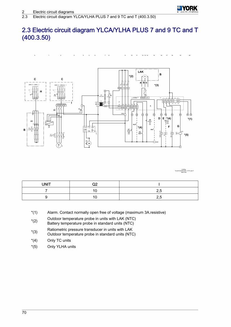
2.3 Electric circuit diagram YLCA/YLHA PLUS 7 and 9 TC and T(400.3.50)
C
B
B
*(3)
*(4)
*(4)
*(5)
I-2545gYLCA/YLHA PLUS 7, 9 TC and T
*(1)
G
D E
F
*(2)C
LAK
a b c
H
I
UNIT Q2 I7 10 2,59 10 2,5
*(1) Alarm. Contact normally open free of voltage (maximum 3A.resistive)
*(2) Outdoor temperature probe in units with LAK (NTC)Battery temperature probe in standard units (NTC)
*(3) Ratiometric pressure transducer in units with LAKOutdoor temperature probe in standard units (NTC)
*(4) Only TC units*(5) Only YLHA units
2 Electric circuit diagrams2.3 Electric circuit diagram YLCA/YLHA PLUS 7 and 9 TC and T (400.3.50)
70

a Green wire FS Water flow switch (TC units)
b White wire FSC Fan speed controller
c Black wire HTP Heater thermal protection
A Electronic control HP High-pressure switch (41 bar)
B The components in the box are standard acces‐sories supplied by the manufacturer K1 Compressor contactor
C The components in the box are not supplied bythe manufacturer K2 Auxiliary heater contactor
D, M1 Compressor LAK Presostatic Low Ambient Kit accessory
E, AH Auxiliary heater LP Low pressure switch (2,5 bar)
F, M3 Pump (TC units) L1, L2, L3 Line phases
H Install on site M2 Fan motor
I “B” mm2 Cu MS Main switch
AH Auxiliary heater N Neutral
B1 Water inlet temperature probe (NTC) Q1 Auxiliary heater thermal magnetic protector
B2 Water outlet temperature probe (NTC) Q2 General / compressor thermal magnetic protec‐tor
B3 Temperature probe *(2) Q3 General thermal magnetic protector, 230V / fan /pump / crankcase heater
B4 *(3) R00 Remote ON / OFF switch
C2 Fan condenser RCH Remote COOL / HEAT switch
F1 Electronic control protection fuse / 24 V [315 mASLOW] switching T Transformer 230 / 24V 20 VA
F2 Fan speed controller fuse V4V, G 4-way valves (on YLHA only)
FC Phase control
Electric circuit diagrams 2Electric circuit diagram YLCA/YLHA PLUS 7 and 9 TC and T (400.3.50) 2.3
71

2.4 Electric circuit diagram YLCA/YLHA PLUS 12 and 15 TC andT (400.3.50)
C
B
B
*(3)
*(4)
*(4)
*(4)
*(5)
I-2533i
*(1)
G
D E
F
*(2)C
LAK
a b c
H
I
UNIT Q2 I12 16 2,515 16 2,5
*(1) Alarm. Contact normally open free of voltage (maximum 3A.resistive)
*(2) Outdoor temperature probe in units with LAK (NTC)Battery temperature probe in standard units (NTC)
*(3) Ratiometric pressure transducer in units with LAKOutdoor temperature probe in standard units (NTC)
*(4) Only TC units*(5) Only YLHA units
2 Electric circuit diagrams2.4 Electric circuit diagram YLCA/YLHA PLUS 12 and 15 TC and T (400.3.50)
72
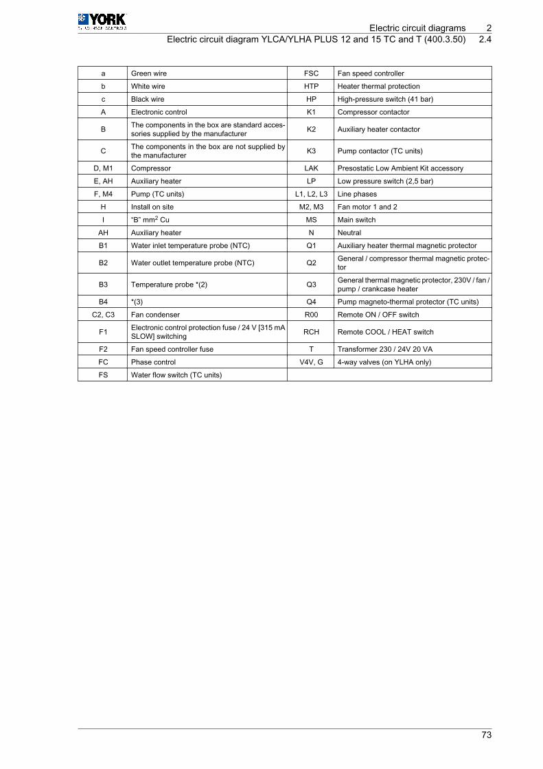
a Green wire FSC Fan speed controller
b White wire HTP Heater thermal protection
c Black wire HP High-pressure switch (41 bar)
A Electronic control K1 Compressor contactor
B The components in the box are standard acces‐sories supplied by the manufacturer K2 Auxiliary heater contactor
C The components in the box are not supplied bythe manufacturer K3 Pump contactor (TC units)
D, M1 Compressor LAK Presostatic Low Ambient Kit accessory
E, AH Auxiliary heater LP Low pressure switch (2,5 bar)
F, M4 Pump (TC units) L1, L2, L3 Line phases
H Install on site M2, M3 Fan motor 1 and 2
I “B” mm2 Cu MS Main switch
AH Auxiliary heater N Neutral
B1 Water inlet temperature probe (NTC) Q1 Auxiliary heater thermal magnetic protector
B2 Water outlet temperature probe (NTC) Q2 General / compressor thermal magnetic protec‐tor
B3 Temperature probe *(2) Q3 General thermal magnetic protector, 230V / fan /pump / crankcase heater
B4 *(3) Q4 Pump magneto-thermal protector (TC units)
C2, C3 Fan condenser R00 Remote ON / OFF switch
F1 Electronic control protection fuse / 24 V [315 mASLOW] switching RCH Remote COOL / HEAT switch
F2 Fan speed controller fuse T Transformer 230 / 24V 20 VA
FC Phase control V4V, G 4-way valves (on YLHA only)
FS Water flow switch (TC units)
Electric circuit diagrams 2Electric circuit diagram YLCA/YLHA PLUS 12 and 15 TC and T (400.3.50) 2.4
73

2.5 Electric circuit diagram YLCA/YLHA PLUS 20 TC and T(400.3.50)
I-2534gYLCA/YLHA PLUS 20 TC and T
400.3.50
L1
L1
L2
Q1
400V, 3 ~,50Hz,
K2(17)
AH
2
1
4
3
MS
1
F1
F1
GO
GNDD4 D2 D1 D3 D5
GND
N1 C1/2 C5N2
C1/2 C3/4N3 N4 N5C3/4
1 2 3 4 5 6
7 8 9 10 11 12
A1
A2(2)
N1 N4N3 N5 C5
GOG
B1GND
B2GND
B3Y
ID5GND
ID3ID4
ID1ID2
B1 B2 B3
B1 B2
GND
B4 V+GND
B4
J1
10 9 8
7 5 4 3 2 1
11121314
6
J2
4 5 6 7 8 9 10 11 12 13 14 15 16 17 18
L1
L3
L2 L3
L2 L3
5
6
A1
A2
M4
K3(18)
A1
A2
3 ~M1
K1(16)
A1
A2(5)
3 ~
(12)Q4
3
4
A1
A2(3)
1 2 30
C3
M3
C2
M2
19 20
B3
L1 L2 L3 N
L1
L1 N
N
Q225A
400V, 3 ~,50Hz,N,
L2 L3
L2 L3
F1315 mA
(0)
N2
HTP
Q3
4A
FSCLOAD
F2
L N Y GND
T230V
0V
20 VA
CH
21
22K1
FS
PHP
41bar
R00
RCH
K1
V4V
2
chiller 2
21
22
1
2
3
4
5
6
1
2
3
4
5
6
1
2
3
4
5
6
62 4
13
14
21
22
FC(8)
L1 L3L2
(16)
14
11FC
(1)
13
14Q4 (3)
K3
A24
PLP
2,5bar K2
C
B*(3)
*(2)
*(1)
G
D E
F
C
a b cH
I
*(1) Alarm. Contact normally open free of voltage (maximum 3A.resistive)*(2) Only TC units*(3) Only YLHA units
2 Electric circuit diagrams2.5 Electric circuit diagram YLCA/YLHA PLUS 20 TC and T (400.3.50)
74

a Green wire FS Water flow switch (TC units)
b White wire FSC Fan speed controller
c Black wire HTP Heater thermal protection
A Electronic control HP High-pressure switch (41 bar)
B The components in the box are standard acces‐sories supplied by the manufacturer K1 Compressor contactor
C The components in the box are not supplied bythe manufacturer K2 Auxiliary heater contactor
D, M1 Compressor K3 Pump contactor (TC units)
E, AH Auxiliary heater LAK Presostatic Low Ambient Kit accessory
F, M4 Pump (TC units) LP Low pressure switch (2,5 bar)
H Install on site L1, L2, L3 Line phases
I 4 mm2 Cu M2, M3 Fan motor 1 and 2
AH Auxiliary heater MS Main switch
B1 Water inlet temperature probe (NTC) N Neutral
B2 Water outlet temperature probe (NTC) Q1 Auxiliary heater thermal magnetic protector
B3 Outdoor temperature probe (NTC) Q2 General / compressor thermal magnetic protec‐tor
B4 Fan / defrost speed control ratiometric pressureprobe Q3 General thermal magnetic protector, 230V / fan /
pump / crankcase heater
C2, C3 Fan condenser Q4 Pump magneto-thermal protector (TC units)
CH Compressor crankcase heater R00 Remote ON / OFF switch
F1 Electronic control protection fuse / 24 V [315 mASLOW] switching RCH Remote COOL / HEAT switch
F2 Fan speed controller fuse T Transformer 230 / 24V 20 VA
FC Phase control V4V, G 4-way valves (on YLHA only)
Electric circuit diagrams 2Electric circuit diagram YLCA/YLHA PLUS 20 TC and T (400.3.50) 2.5
75

2.6 Electric circuit diagram YLCA 27 TC, YLHA PLUS 27(400.3.50)
I-2565fYLCA 27 TC
YLHA PLUS 27400.3.50
L1
L1
L2
Q1
400V, 3 ~,50Hz,
K2(17)
AH
2
1
4
3
MS
1
F1
F1
GO
GNDD4 D2 D1 D3 D5
GND
N1 C1/2 C5N2
C1/2 C3/4N3 N4 N5C3/4
1 2 3 4 5 6
7 8 9 10 11 12
A1
A2(2)
N1 N4N3 N5 C5
GOG
B1GND
B2GND
B3Y
ID5GND
ID3ID4
ID1ID2
B1 B2 B3
B1 B2
GND
B4 V+GND
B4
J1
10 9 8
7 5 4 3 2 1
11121314
6
J2
4 5 6 7 8 9 10 11 12 13 14 15 16 17 18
L1
L3
L2 L3
L2 L3
5
6
A1
A2
M4
K3(18)
A1
A2
3 ~M1
K1(16)
A1
A2(5)
3 ~
(12)Q4
3
4
A1
A2(3)
1 2 30
C3
M3
C2
M2
19 20
B3
L1 L2 L3 N
L1
L1 N
N
Q225A
400V, 3 ~,50Hz,N,
L2 L3
L2 L3
F1315 mA
(0)
N2
HTP
Q3
FSCLOAD
F2
L N Y GND
T230V
0V
20 VA
CH
21
22K1
FS
R00
RCH
K1
V4V
2
chiller 2
21
22
1
2
3
4
5
6
1
2
3
4
5
6
1
2
3
4
5
6
62 4
13
14
21
22
FC(8)
L1 L3L2
(16)
14
11FC
(1)
13
14Q4
K3
A24
PLP
2,5bar K2
5
6
PHP
41bar
(3)
PTV1
PTV2
C
B*(3)
*(2)
*(1)
G
D E F
C
a b cH
I
*(1) Alarm. Contact normally open free of voltage (maximum 3A.resistive)*(2) Only TC units*(3) Only YLHA units
2 Electric circuit diagrams2.6 Electric circuit diagram YLCA 27 TC, YLHA PLUS 27 (400.3.50)
76
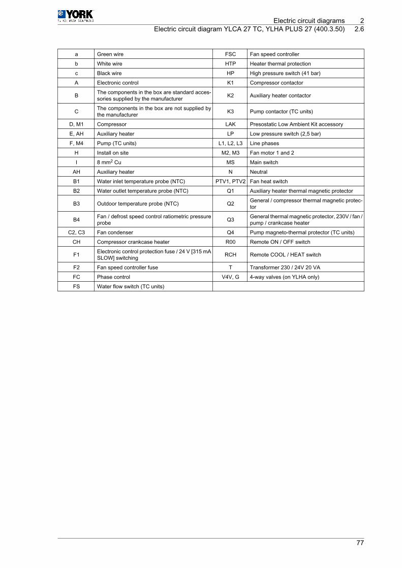
a Green wire FSC Fan speed controller
b White wire HTP Heater thermal protection
c Black wire HP High pressure switch (41 bar)
A Electronic control K1 Compressor contactor
B The components in the box are standard acces‐sories supplied by the manufacturer K2 Auxiliary heater contactor
C The components in the box are not supplied bythe manufacturer K3 Pump contactor (TC units)
D, M1 Compressor LAK Presostatic Low Ambient Kit accessory
E, AH Auxiliary heater LP Low pressure switch (2,5 bar)
F, M4 Pump (TC units) L1, L2, L3 Line phases
H Install on site M2, M3 Fan motor 1 and 2
I 8 mm2 Cu MS Main switch
AH Auxiliary heater N Neutral
B1 Water inlet temperature probe (NTC) PTV1, PTV2 Fan heat switch
B2 Water outlet temperature probe (NTC) Q1 Auxiliary heater thermal magnetic protector
B3 Outdoor temperature probe (NTC) Q2 General / compressor thermal magnetic protec‐tor
B4 Fan / defrost speed control ratiometric pressureprobe Q3 General thermal magnetic protector, 230V / fan /
pump / crankcase heater
C2, C3 Fan condenser Q4 Pump magneto-thermal protector (TC units)
CH Compressor crankcase heater R00 Remote ON / OFF switch
F1 Electronic control protection fuse / 24 V [315 mASLOW] switching RCH Remote COOL / HEAT switch
F2 Fan speed controller fuse T Transformer 230 / 24V 20 VA
FC Phase control V4V, G 4-way valves (on YLHA only)
FS Water flow switch (TC units)
Electric circuit diagrams 2Electric circuit diagram YLCA 27 TC, YLHA PLUS 27 (400.3.50) 2.6
77

2.7 Electric circuit diagram YLCA PLUS 5 ÷ 9 MCS (230.1.50)SOFT START
L1
L1 N
N
Q2Amp
230V, 1 ~,50Hz,N, PE
L1
L1
L1 N
N
Q1
230V, 1 ~,50Hz,N,
K2
(15)
AH
2
1
4
3
N
(14)
C1
MS
1
C2
M2
F1
F1
F1315 mA
GO
GNDD4 D2 D1 D3 D5
GND
N1 C1/2 C5N2
C1/2 C3/4N3 N4 N5C3/4
1 2 3 4 5 6
7 8 9 10 11 12
N1 N4N3 N5 C5
GOG
B1GND
B2GND
B3Y
ID5GND
ID3ID4
ID1ID2
B1 B2 B3
B1 B2 B3
GND
B4 V+GND
B4
J1
10 9 8
7 5 4 3 2 1
11121314
6
J2
4 5 6 7 8 999 10 11 12 13 14 15 16 17 18
L1 N
1 2 30
2
1
4
3
B4
RRCL1SONN
SS
Q3
3A
FSCLOAD
F2
L N Y GND
T230V
0V
20 VA
FSPHP
41bar
R00
RCH
M3V4V
2
��chiller 2
PLP
2,5bar
A
24
(0)
N2
HTP
K2
M1S C
R
I-2582bYLHA PLUS 5, 7, 9 MCS
230.1.50
C
B
*(4)
*(5)
*(4)
*(2)
LAKB
*(3)
*(1)
G
D E
F
C a b c
HH
I
UNIT Q2 I5 20 2,57 25 49 32 6
*(1) Alarm. contact normally open free of voltage (maximum 3A.resistive)
*(2) Outdoor temperature probe in units with LAK (NTC)Battery temperature probe in standard units (NTC)
*(3) Ratiometric pressure transducer in units with LAKOutdoor temperature probe in standard units (NTC)
*(4) Only MC units*(5) Only YLHA units
2 Electric circuit diagrams2.7 Electric circuit diagram YLCA PLUS 5 ÷ 9 MCS (230.1.50) SOFT START
78
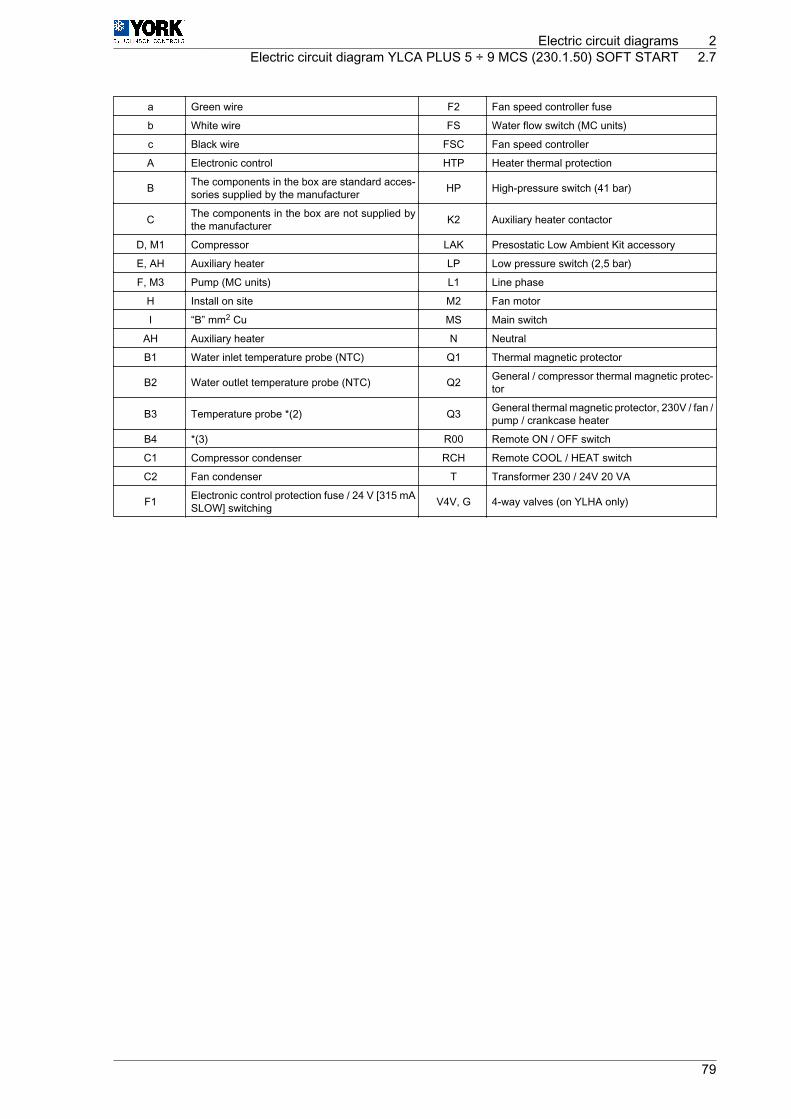
a Green wire F2 Fan speed controller fuse
b White wire FS Water flow switch (MC units)
c Black wire FSC Fan speed controller
A Electronic control HTP Heater thermal protection
B The components in the box are standard acces‐sories supplied by the manufacturer HP High-pressure switch (41 bar)
C The components in the box are not supplied bythe manufacturer K2 Auxiliary heater contactor
D, M1 Compressor LAK Presostatic Low Ambient Kit accessory
E, AH Auxiliary heater LP Low pressure switch (2,5 bar)
F, M3 Pump (MC units) L1 Line phase
H Install on site M2 Fan motor
I “B” mm2 Cu MS Main switch
AH Auxiliary heater N Neutral
B1 Water inlet temperature probe (NTC) Q1 Thermal magnetic protector
B2 Water outlet temperature probe (NTC) Q2 General / compressor thermal magnetic protec‐tor
B3 Temperature probe *(2) Q3 General thermal magnetic protector, 230V / fan /pump / crankcase heater
B4 *(3) R00 Remote ON / OFF switch
C1 Compressor condenser RCH Remote COOL / HEAT switch
C2 Fan condenser T Transformer 230 / 24V 20 VA
F1 Electronic control protection fuse / 24 V [315 mASLOW] switching V4V, G 4-way valves (on YLHA only)
Electric circuit diagrams 2Electric circuit diagram YLCA PLUS 5 ÷ 9 MCS (230.1.50) SOFT START 2.7
79

2.8 Electric circuit diagram YLCA PLUS 12 MCS (230.1.50) SOFTSTART
L1
L1 N
N
40Amp
230V, 1 ~,50Hz,N, PE
L1
L1
L1 N
N
Q1
230V, 1 ~,50Hz,N,
K2
(15)
AH
2
1
4
3
N
(14)
C1
MS
1
C2
M2
C2
C1 M2M4
C3
M3
F1
F1
F1315 mA
GO
GNDD4 D2 D1 D3 D5
GND
N1 C1/2 C5N2
C1/2 C3/4N3 N4 N5C3/4
1 2 3 4 5 6
7 8 9 10 11 12
N1 N4N3 N5 C5
GOG
B1GND
B2GND
B3Y
ID5GND
ID3ID4
ID1ID2
B1 B2 B3
B1 B2 B3
GND
B4 V+GND
B4
J1
10 9 8
7 5 4 3 2 1
11121314
6
J2
4 5 6 7 8 999 10 11 12 13 14 15 16 17 18
L1 N
1 2 30
2
1
4
3
B4
RRCL1SONN
SS
Q3
3A
Q3
3A
FSCLOAD
F2
L N Y GND
T230V
0V
20 VA
FSPHP
41bar
R00
RCH
V4V
2
��chiller 2
PLP
2,5bar
A
24
(0)
N2
HTP
K2 K3
M1S C
R
I-2583dYLHA PLUS 12 MCS
230.1.50
1K3(16)
5
C
B
*(4)
*(5)
*(4)
*(2)
LAKB
*(3)
*(1)
G
D E
F
C a b c
HH
I
*(1) Alarm. contact normally open free of voltage (maximum 3A.resistive)
*(2) Outdoor temperature probe in units with LAK (NTC)Battery temperature probe in standard units (NTC)
*(3) Ratiometric pressure transducer in units with LAKOutdoor temperature probe in standard units (NTC)
*(4) Only MC units*(5) Only YLHA units
2 Electric circuit diagrams2.8 Electric circuit diagram YLCA PLUS 12 MCS (230.1.50) SOFT START
80

a Green wire FSC Fan speed controller
b White wire HTP Heater thermal protection
c Black wire HP High-pressure switch (41 bar)
A Electronic control K2 Auxiliary heater contactor
B The components in the box are standard acces‐sories supplied by the manufacturer K3 Pump contactor (TC units)
C The components in the box are not supplied bythe manufacturer LAK Presostatic Low Ambient Kit accessory
D, M1 Compressor LP Low pressure switch (2,5 bar)
E, AH Auxiliary heater L1 Line phase
F, M4 Pump (MC units) M2, M3 Fan motor
H Install on site MS Main switch
I 10 mm2 Cu N Neutral
AH Auxiliary heater Q1 Auxiliary heater thermal magnetic protector
B1 Water inlet temperature probe (NTC) Q2 General / compressor thermal magnetic protec‐tor
B2 Water outlet temperature probe (NTC) Q3 General thermal magnetic protector, 230V / fan /pump / crankcase heater
B3 Temperature probe *(2) R00 Remote ON / OFF switch
B4 *(3) RCH Remote COOL / HEAT switch
C2, C3 Fan condenser SS Gentle starter
F1 Electronic control protection fuse / 24 V [315 mASLOW] switching T Transformer 230 / 24V 20 VA
F2 Fan speed controller fuse V4V, G 4-way valves (on YLHA only)
FS Water flow switch (MC units)
Electric circuit diagrams 2Electric circuit diagram YLCA PLUS 12 MCS (230.1.50) SOFT START 2.8
81