agricultural building ventilation systems … · 2.3.3 impacts of climate change on barn...
TRANSCRIPT

AGRICULTURAL BUILDING VENTILATION
SYSTEMS
306-412-1
MARCH 2016

ACKNOWLEDGEMENTS
Funding for this project has been provided by the Governments of Canada and British Columbia through Growing Forward 2, a federal-provincial-territorial
initiative
DISCLAIMER
Opinions expressed in this document are those of the author and not necessarily those of the Governments of Canada and British Columbia. The Governments of Canada and British Columbia, and their directors, agents,
employees, or contractors will not be liable for any claims, damages, or losses of any kind whatsoever arising out of the use of, or reliance upon, this
information. The report was prepared exclusively for the BC Ministry of Agriculture by Amec Foster Wheeler Americas Limited (Amec Foster Wheeler). The quality of information, conclusions and estimates contained herein is consistent with the level of effort involved in Amec Foster Wheeler's services and based on:
i) information available at the time of preparation, ii) data supplied by outside sources and, iii) the assumptions, conditions and qualifications set forth in
this report.
This report is intended to be used by the BC Ministry of Agriculture only, subject to the terms and conditions of its contract with Amec Foster Wheeler. Any other use of, or reliance on, this report by any third party is at that party’s
sole risk.
Prepared by: Amec Foster Wheeler
Mining & Metals Americas www.amecfw.com

TOC
C O N T E N T S
1.0 INTRODUCTION .............................................................................................................................. 1 1.1 Summary ............................................................................................................................. 1
2.0 BACKGROUND ................................................................................................................................ 2 2.1 The Market........................................................................................................................... 2
2.1.1 Dairy ....................................................................................................................... 2 2.1.2 Poultry..................................................................................................................... 3 2.1.3 Swine ...................................................................................................................... 4
2.2 Animal Demographics in BC................................................................................................ 4 2.2.1 BCStats Development Regions .............................................................................. 5 2.2.2 Distribution of Dairy, Poultry and Swine ................................................................. 7
2.3 Climate in B.C. ..................................................................................................................... 8 2.3.1 Climatic Conditions in B.C. ..................................................................................... 8 2.3.2 Summary of Climate Change in British Columbia .................................................. 9 2.3.3 Impacts of Climate Change on Barn Ventilation .................................................. 10
3.0 AGRICULTURAL BUILDING HEATING, VENTILATION, AND AIR CONDITIONING (HVAC) SYSTEMS ....................................................................................................................................... 11 3.1 Purposes of Agricultural Building HVAC Systems ............................................................ 11 3.2 Ventilation Systems for Livestock and Poultry Housing .................................................... 12
3.2.1 Fans ...................................................................................................................... 12 3.2.2 Natural Ventilation ................................................................................................ 13 3.2.3 Dual Ventilation .................................................................................................... 16 3.2.4 Exhaust Ventilation Systems ................................................................................ 18 3.2.5 Tunnel Ventilation ................................................................................................. 20 3.2.6 Pit Ventilation ........................................................................................................ 23 3.2.7 Combination Pressure / Exhaust Systems ........................................................... 25 3.2.8 Neutral Pressure Systems .................................................................................... 26 3.2.9 Positive Pressure Ventilation Systems ................................................................. 27
3.3 Heating Systems ............................................................................................................... 29 3.3.1 In-Floor Heating .................................................................................................... 29 3.3.2 Gas-Fired Radiant Heating ................................................................................... 31 3.3.3 Convective Heating .............................................................................................. 33 3.3.4 Unit Heaters .......................................................................................................... 34
3.4 Cooling and Circulation Systems ...................................................................................... 36 3.4.1 Air Circulation Fans .............................................................................................. 36 3.4.2 Ducted Recirculation Systems ............................................................................. 39 3.4.3 Cooling with Low-Pressure Water Sprinklers or Drippers .................................... 41 3.4.4 Evaporative Cooling with Direct High–Pressure Misting ...................................... 43 3.4.5 Evaporative Cooling Pads .................................................................................... 45 3.4.6 Evaporative Cooling in Forced Air Systems – Indirect ......................................... 47
3.5 Heat Recovery and Alternatives ........................................................................................ 49 3.5.1 Air-to-Air Heat Recovery....................................................................................... 49 3.5.2 Building Thermal Capacitance ............................................................................. 50 3.5.3 External Thermal Capacitance ............................................................................. 51 3.5.4 Earth Tube System ............................................................................................... 52 3.5.5 Transpired Solar Walls ......................................................................................... 54 3.5.6 Passive Solar Air Heater ...................................................................................... 56

TOC
3.5.7 Greenhouse Barns ............................................................................................... 58 3.5.8 Heat Pumps for Heating and Cooling ................................................................... 58
3.6 Noise, Odour, Dust and Biosecurity .................................................................................. 60 3.6.1 General ................................................................................................................. 60 3.6.2 Noise Control Earth Berms ................................................................................... 62 3.6.3 Noise Barrier Fences ............................................................................................ 63 3.6.4 Vegetative Buffers ................................................................................................ 64 3.6.5 Misting Showers for Dust Abatement ................................................................... 65 3.6.6 Building Electrostatic Charge for Dust Abatement ............................................... 66 3.6.7 Ducted Sound Attenuators ................................................................................... 68 3.6.8 Biosecurity: Air Filtration for Exhaust Air Cleaning ............................................... 69 3.6.9 Biosecurity: Intake Air Biofiltration ........................................................................ 70 3.6.10 Biofiltration for Complete Exhaust System Air Cleaning ...................................... 71 3.6.11 Wet Scrubbers for Exhaust Air Cleaning .............................................................. 73 3.6.12 UV Light for Exhaust Air Cleaning ........................................................................ 75 3.6.13 Non-Thermal Plasma for Exhaust Air Odour Abatement ..................................... 76 3.6.14 Windbreak Walls ................................................................................................... 77 3.6.15 Exhaust Stacks ..................................................................................................... 79 3.6.16 Site Selection and Yard Layout ............................................................................ 80
4.0 THEORETICAL CONSIDERATIONS FOR VENTILATION OF AGRICULTURAL BUILDINGS .... 81 4.1 General .............................................................................................................................. 81 4.2 Energy and Mass Balance................................................................................................. 81 4.3 Properties of Moist Air ....................................................................................................... 81
4.3.1 General ................................................................................................................. 81 4.3.2 Dry Bulb Temperature .......................................................................................... 83 4.3.3 Wet Bulb Temperature ......................................................................................... 83 4.3.4 Dew Point Temperature........................................................................................ 83 4.3.5 Relative Humidity .................................................................................................. 83 4.3.6 Humidity Ratio ...................................................................................................... 84 4.3.7 Specific Volume .................................................................................................... 84 4.3.8 Enthalpy ................................................................................................................ 85
4.4 Moist Air Conditioning Processes ...................................................................................... 85 4.4.1 General ................................................................................................................. 85 4.4.2 Sensible Heating .................................................................................................. 86 4.4.3 Sensible Cooling ................................................................................................... 87 4.4.4 Isothermal Humidification (Adding Latent Heat) ................................................... 87 4.4.5 Adiabatic Cooling (Evaporative Cooling) .............................................................. 88 4.4.6 Heating and Humidifying of Air by Animals .......................................................... 89 4.4.7 Cooling and Dehumidifying .................................................................................. 92
4.5 Fresh Air Intake ................................................................................................................. 92 4.5.1 General ................................................................................................................. 92 4.5.2 Required Fresh Air Flowrate ................................................................................ 92
5.0 SYSTEM DESIGN .......................................................................................................................... 96 5.1 System Design Flowcharts ................................................................................................ 96
5.1.1 Ventilation System Design ................................................................................... 97 5.1.2 Odour, Noise, Dust and Biosecurity ................................................................... 101
5.2 System Design Checklists ............................................................................................... 102 5.2.1 General ............................................................................................................... 102 5.2.2 Design Criteria .................................................................................................... 102 5.2.3 Energy Saving Considerations ........................................................................... 102

TOC
5.2.4 Fans .................................................................................................................... 102 5.2.5 Distribution of Fresh Air into the Barn ................................................................ 103 5.2.6 Air Filtration ........................................................................................................ 103 5.2.7 Maintainability ..................................................................................................... 103 5.2.8 Controls .............................................................................................................. 104 5.2.9 System Supplier Documentation Requirements ................................................ 104
5.3 Sample System Design Software Application ................................................................. 105
6.0 MAINTENANCE AND MONITORING CHECKLISTS................................................................... 113 6.1 General ............................................................................................................................ 113 6.2 Fans ................................................................................................................................. 113 6.3 Electric Heaters ............................................................................................................... 114 6.4 Ductwork .......................................................................................................................... 114
7.0 STATE OF THE INDUSTRY ........................................................................................................ 115 7.1 Ventilation Survey ............................................................................................................ 115
7.1.1 Dairy Ventilation Trends ..................................................................................... 116 7.1.2 Poultry Ventilation Trends .................................................................................. 118 7.1.3 Swine Ventilation Trends .................................................................................... 120
8.0 REVIEW OF RELEVANT LITERATURE REGARDING VENTILATION, AND CONTROL OF DUST, ODOUR, AND NOISE ....................................................................................................... 122 8.1 Government Handbooks – Canada ................................................................................. 122 8.2 Government Handbooks – United States ........................................................................ 123 8.3 Government Handbooks – Europe .................................................................................. 124 8.4 Codes, Standards and Regulations – Canada ................................................................ 125
8.4.1 National Farm Building Code of Canada ............................................................ 125 8.4.2 BC Occupational Health and Safety Regulation (OH&S) ................................... 125 8.4.3 Minimum Distance Separation Formula ............................................................. 125 8.4.4 Other ................................................................................................................... 126
8.5 Codes, Standards and Regulations – USA ..................................................................... 127 8.6 Codes, Standards and Regulations – Europe ................................................................. 127 8.7 Research Papers and Literature Review ......................................................................... 128
8.7.1 Ventilation ........................................................................................................... 128 8.7.2 Dust, Odour and Noise ....................................................................................... 132
8.8 Market Statistics .............................................................................................................. 134
F I G U R E S
Figure 1 - BCStats Development Regions Map ............................................................................................ 6 Figure 2 - Abbotsford BC Temperature Trend ............................................................................................... 9 Figure 3 - General Agricultural Building HVAC Concept .............................. Error! Bookmark not defined. Figure 4 Natural Ventilation with Side Walls and End Walls Concept ......................................................... 16 Figure 5 - Natural Ventilation with Chimneys or Continuous Ridges Concept ............................................ 16 Figure 6 - Dual Ventilation Concept............................................................................................................. 17 Figure 7 - Exhaust Ventilation (inlets both sides) System Concept ............................................................ 18 Figure 8 - Exhaust Ventilation (cross-ventilation) System Concept ............................................................ 19 Figure 9 - Exhaust Ventilation with Ducted Recirculation System Concept ................................................ 19 Figure 10 - Forced-Air Tunnel Ventilation Concept ..................................................................................... 21 Figure 11 - Other Tunnel Ventilation Configurations ................................................................................... 22

TOC
Figure 12 - Attic Inlet Plenum with Pit and Side Wall Exhaust Fans Concept ............................................ 24 Figure 13 - Combination Pressure/Exhaust System Concept ..................................................................... 25 Figure 14 - Forced Air –Neutral Pressure System Concept ........................................................................ 26 Figure 15 - Distributed Forced Fresh Air with Natural Ventilation ............................................................... 27 Figure 16 - Positive Pressure Ventilation System Concept ......................................................................... 28 Figure 17 - Ducted Positive Pressure System Concept .............................................................................. 28 Figure 18 - In-Floor Heating Concept .......................................................................................................... 30 Figure 19 - Gas-Fired Radiant Heating Concept ......................................................................................... 32 Figure 20 - Convective Heating Concept .................................................................................................... 33 Figure 21 - Unit Heaters Concept ................................................................................................................ 35 Figure 22 - Horizontal Air Circulator Fans Concept ..................................................................................... 36 Figure 23 - Down-Draft High-Volume Low-Speed (HVLS) Circulation System Concept ............................ 37 Figure 24 - Ducted Recirculation System Concept ..................................................................................... 40 Figure 25 - Cooling with Low-Pressure Water Sprinklers or Drippers ......................................................... 41 Figure 26 - Evaporative Cooling with Direct High–Pressure Misting Concept ............................................ 43 Figure 27 - Direct Evaporative Cooling with Media Concept ....................................................................... 45 Figure 28 - Evaporative Cooling in Forced Air Systems – Indirect – Concept ............................................ 48 Figure 29 - Air to Air Heat Recovery Concept ............................................................................................. 49 Figure 30 - Building Thermal Capacitance Concept.................................................................................... 50 Figure 31 - External Thermal Capacitance Concept ................................................................................... 51 Figure 32 - Earth Tube System Concept ..................................................................................................... 53 Figure 33 - Transpired Solar Wall Concept ................................................................................................. 54 Figure 34 - Solar Ventilation Wall with Heat Storage Concept .................................................................... 55 Figure 35 - Passive Solar Air Heater Concept ............................................................................................ 56 Figure 36 - Heat Pump Systems ................................................................................................................. 59 Figure 37 - Noise Control Earth Berm Concept ........................................................................................... 62 Figure 38 - Noise Barrier Fence Concept .................................................................................................... 63 Figure 39 - Vegetative Buffers Concept ...................................................................................................... 64 Figure 40 - Misting Showers for Dust Abatement Concept ......................................................................... 65 Figure 41 - Building Electrostatic Charge for Dust Abatement Concept ..................................................... 66 Figure 42 - Ducted Sound Attenuators Concept ......................................................................................... 68 Figure 43 - Air Filtration for Exhaust Air Cleaning Concept ........................................................................ 69 Figure 44 - Intake Air Filtration Concept ...................................................................................................... 70 Figure 45 - Biofiltration on Building Exhaust Concept ................................................................................. 71 Figure 46 - Wet Scrubber Concept .............................................................................................................. 73 Figure 47 - UV Light for Exhaust Air Cleaning Concept .............................................................................. 75 Figure 48 - Non-Thermal Plasma for Exhaust Air Odour Abatement Concept ........................................... 76 Figure 49 - Windbreak Wall Concept .......................................................................................................... 77 Figure 50 - Exhaust Stack Concept ............................................................................................................. 79 Figure 51 - Energy and Mass Balance ........................................................................................................ 81 Figure 52 - Psychrometric Chart .................................................................................................................. 82 Figure 53 - Psychrometric Processes.......................................................................................................... 86 Figure 54 Input Data .................................................................................................................................. 106 Figure 55 - Ventilation Summary ............................................................................................................... 107 Figure 56 - Ventilation Graph .................................................................................................................... 108 Figure 57 - Ventilation Chart ...................................................................................................................... 109

TOC
Figure 58 - Heat Balance Chart ................................................................................................................. 110 Figure 59 - Internal Air Circulation ............................................................................................................. 111 Figure 60 - Tunnel Ventilation Chart ......................................................................................................... 112
Page 1 of 134
1.0 INTRODUCTION 1.1 Summary
This report was prepared in collaboration with the BC Ministry of Agriculture. The report identifies what can be done and what is currently being done with respect to livestock building environmental control for the BC dairy, poultry, and swine industries.
To complement the knowledge and expertise of Amec Foster Wheeler and the BC Ministry of Agriculture, interviews were conducted with ventilation system suppliers and veterinarians that serve the BC agricultural industry. Questionnaires were also distributed to various producers.
A brief overview of relevant background information is presented including market conditions, climate conditions, and animal demographics in British Columbia.
The bulk of this report serves as a compendium of the majority of systems and system configurations used to control the environment in and around livestock and poultry housing.
This report also identifies the various systems and equipment that are used worldwide and may be suitable for use in British Columbia. Included are typical ventilation system configurations, heating systems, cooling and circulation systems, heat recovery and alternative systems.
Also included are various systems and equipment that are used for noise, odour, dust abatement and biosecurity. For each of these items, the concept is described and the benefits and drawbacks are identified. This area is especially of concern in the Fraser Valley area where there is an interface between rural and urban landowners.
For each of the concepts presented, some common ranges of operational parameters are included for the sole purpose of helping the reader gain a better understanding of the magnitudes of important variables including materials, temperatures, pressures and velocities. It is important to note that this information should not be relied upon for detailed system design. Each application must be assessed individually by a qualified engineer. It is outside the scope of this report to provide detailed application instructions.
Criteria for the selection and sizing of equipment are discussed and the applicable engineering principles are introduced to help the reader understand the logic involved in the application of various systems.
The current state of the industry is summarized. The types of systems and equipment that are commonly used in British Columbia are identified.
Page 2 of 134
A review of relevant literature is summarized in this report. Referenced documents are graded in terms of level of accuracy, relevance and usefulness. A high-level description of their relevant content is included.
2.0 BACKGROUND 2.1 The Market 2.1.1 Dairy
Dairy farming in Canada is under supply management legislation. Every dairy farmer has a production quota that cannot be exceeded without penalty. To enter the dairy industry, one must purchase this quota in order to have the right to produce. In turn, the price dairy farmers receive for their milk is based on cost of production. Therefore, increases in costs, such as higher energy prices, are reflected in increases in revenue.
The total number of dairy cows in British Columbia has decreased by 1.1% since 2009 to 72,600 in 20141. However, the production of milk for the same year had increased by 1.03% relative to 2013 to 688,328 kilolitres2. The price farmers received rose by 1.02% relative to 2013. The overall number of farms has shown a decline by 0.98% in 2011 compared to 2010. On average, dairy cattle and milk production accounts for 3.4% of the total number of agricultural farms3.
Dairy farming is also under pressure from world trading partners (as are all supply management commodities), including the potential signing of the TPP (Trans Pacific Partnership) and, at some point in the future, dairy farmers are likely to find the supply management system being changed significantly. There will be increasing competitiveness pressures from imported dairy products as import tariffs are reduced. If support for supply management wanes over time, dairy farmers will no longer be able to recover higher production costs through controlled increases in selling prices.
Most of the B.C. dairy herds are located in the Lower Mainland, southeastern Vancouver Island, and the north Okanagan-Shuswap area, with an average herd size of 135 cows4. About 73% of the province’s milk is produced in the Fraser Valley, whereas the Okanagan‒Shuswap and Vancouver Island regions account for 14% and 9% of total production, respectively. Other smaller production areas include the Bulkley Valley, the Kootenays, the Cariboo and the Peace River4.
Dairy farms are either set up as tie-stall operations or free-stall operations. Larger operations are all free-stall. Dairy farms are highly dependent on electrical energy to operate ventilation systems. Even natural ventilation systems require power for controllers, actuators, circulation fans, cooling systems, and the like.

Page 3 of 134
2.1.2 Poultry
The poultry industry is another supply managed agricultural sector. Broiler chicken, egg and turkey production are all regulated and quota driven. The price received by producers is based on a cost-of-production formula.
British Columbia accounts for 15.5% of poultry production in the country6. In 2013, there were 161,613,000 chickens and 21,345,000 turkeys, representing a 1.8% growth relative to the previous five years1. Egg production is more significant with 78,658,000 dozen eggs and a 3.9% five-year growth in 20131. Poultry prices have shown a steady increase from 2008-2013, with a 12.1% price increase for chicken, 9.6% increase for turkeys, and 15.9% increase for egg prices received by B.C. livestock producers1. Per capita consumption of chicken and turkey has, however, decreased by 2.4% and 1.0%, respectively, in the past five years. Only egg consumption has risen by 9.1% to 14.3 dozen/capita in 20131.
In 2011, there were 331 chicken farms in British Columbia, producing about 154 million kilograms of meat and generating $351 million in farm cash receipts7. Chicken production is one of BC’s top three agricultural industries, representing 13.4% of total farm cash receipts. Including chicken and turkey producers, processers and allied industries, the BC poultry industry value chain generates approximately $2.4 billion in economic output and contributes $712.4 million in gross domestic product (GDP) to BC’s economy7.
In 2011, there were 63 turkey farms in British Columbia, producing about 24.9 million kilograms of turkey valued at $45.7 million, representing 1.7% of total farm cash receipts in the province7. BC turkey production ranks third among Canadian provinces, accounting for 12.9% of all Canadian turkey farm cash receipts7.
In 2011, there were 136 table egg farms in British Columbia and sales were valued at $127.6 million, representing 4.9% of total farm cash receipts in BC and 16.9% of all Canadian table egg farm cash receipts7.
The poultry industry is one of the few very healthy agricultural sectors, primarily because of the continued growth in demand for poultry products along with the supply-demand nature of the market.
Poultry production follows a fairly rigid ‘formula’ that contributes to its economic success. From the type of buildings constructed to the breed of chicken grown to the kinds of feed formulated to the control of other important operational parameters, poultry production is highly technical and well managed.
Poultry production is carried out under controlled environmental conditions and is highly dependent on electricity for ventilation, lighting, feed handling, manure handling,

Page 4 of 134
egg collection, cooling during for storage requirements. Electricity is also often used to provide warmth to young chicks in cold weather periods.
2.1.3 Swine
Annually, about 156,000 – 188,800 hogs are processed from British Columbia farm sources, which accounts for 10% of the pork consumed within the province5. The B.C. hog industry has been served by two major meat plants located in the Fraser Valley5. The majority of the industry’s hog farms are family owned and operated, and are concentrated in the Fraser Valley between Chilliwack and Aldergrove5. The swine industry has shown an 11.2% decline in pig production over the past five years1.
Profitability in the pork sector has remained quite low and the BC industry consists of about 20 commercial producers. It should be noted that BC does have the land base, feed production capability and market access for a viable and sustainable pork industry. Maintaining competitiveness with other jurisdictions is the key to success.
Pork producers are quick to adopt new technologies and management options to enhance productivity and/or reduce costs. The Canadian pig also has a good reputation for high quality pork in international markets.
Environmental issues continue to plague the pork sector. Odour and nutrient load on the environment from large swine operations have resulted in highly restrictive land use regulations. The challenges associated with compliance can add significantly to the cost of production.
Swine operations are divided into three main categories: farrow-to-finish, farrow-wean and finishing pig operations. All commercial pork production takes place under controlled environment conditions. Farrow-to-finish operations produce pigs from birth to market. Large operations will likely separate each phase of production into separate facilities, often on neighbouring farms. A farrow-to-wean operation produces a pig from birth to 28 kg (60 lb), at which time it is sold to another producer who operates a finishing facility that grows the pig to a market weight of about 120 kg (260 lb). A unique “round hog” market also exists in BC. This market consists of animals being sold well below the typical market weight to suit an ethnic demand for a given dressed weight as low as 30 kg (65 lb).
Most commercial swine facilities are highly dependent on electricity for ventilation and heating. Spot heating for young piglets is commonly utilized.
2.2 Animal Demographics in BC Census data is summarized in this section for eight defined regions in British Columbia.

Page 5 of 134
2.2.1 BCStats Development Regions
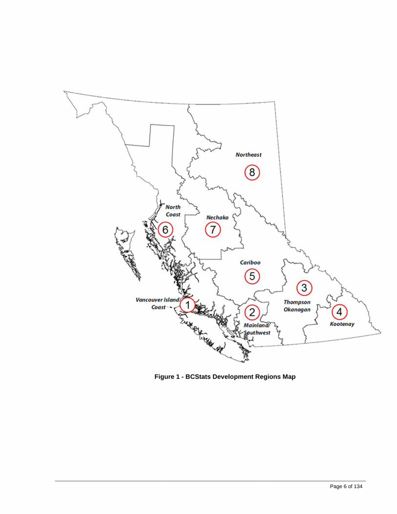
Figure 1 is a map of British Columbia with the various BCStats development regions shown. Table 1 includes a description of the selected regions.
Table 1 – BCStats Development Regions in B.C.
Development Region
Included Regional Districts
1 Vancouver Island-Coast
Alberni-Clayoquot, Capital, Central Coast, Comox Valley, Cowichan Valley, Mount Waddington, Nanaimo, Powell River, Strathcona
2 Lower Mainland-Southwest
Fraser Valley, Greater Vancouver, Squamish-Lillooet, Sunshine Coast
3 Thompson-Okanagan
Central Okanagan, Columbia-Shuswap, North Okanagan, Thompson-Nicola
4 Kootenay Central Kootenay, East Kootenay, Kootenay Boundary 5 Cariboo Cariboo, Fraser-Fort George 6 North Coast Kitimat-Stikine, Skeena-Queen Charlotte 7 Nechako Bulkley-Nechako, Stikine 8 Northeast Northern Rockies, Peace River
Page 6 of 134
Figure 1 - BCStats Development Regions Map
Page 7 of 134
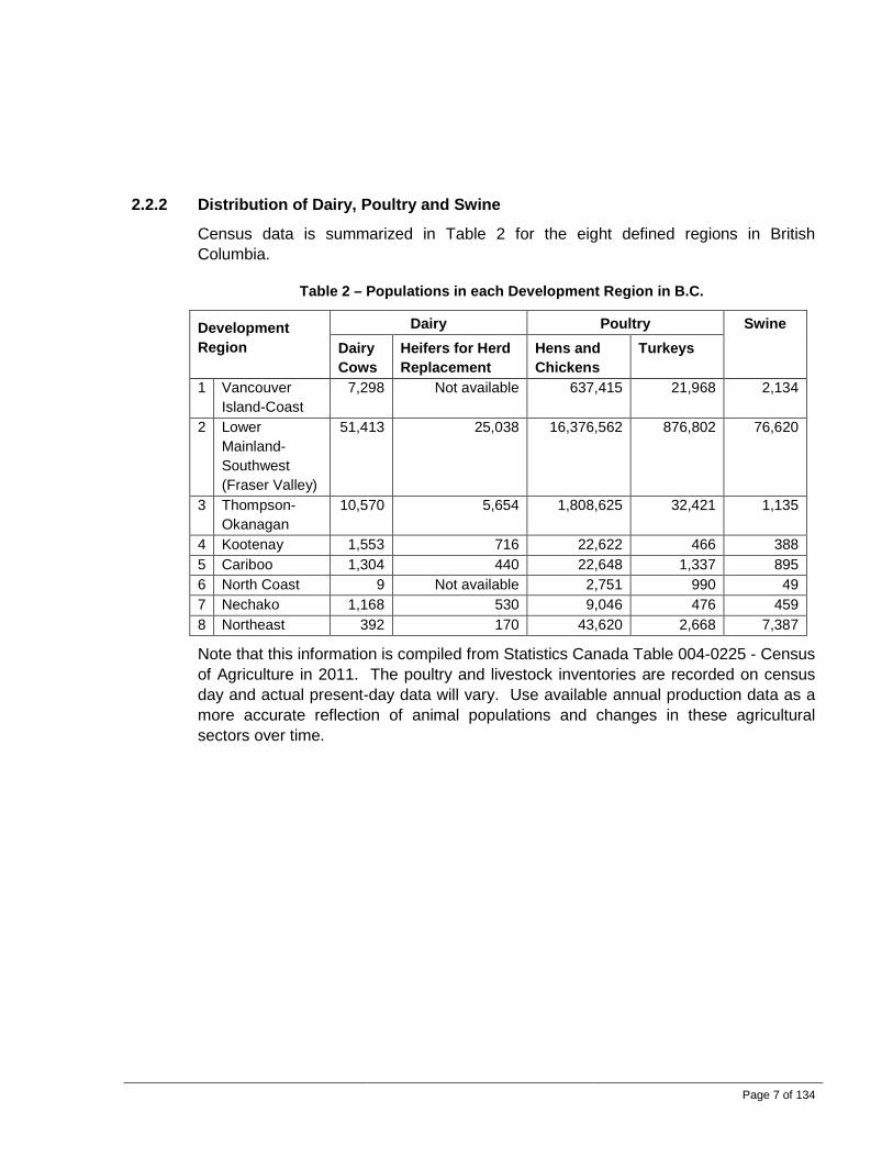
2.2.2 Distribution of Dairy, Poultry and Swine
Census data is summarized in Table 2 for the eight defined regions in British Columbia.
Table 2 – Populations in each Development Region in B.C.
Development Region
Dairy Poultry Swine Dairy Cows
Heifers for Herd Replacement
Hens and Chickens
Turkeys
1 Vancouver Island-Coast
7,298 Not available 637,415 21,968 2,134
2 Lower Mainland-Southwest (Fraser Valley)
51,413 25,038 16,376,562 876,802 76,620
3 Thompson-Okanagan
10,570 5,654 1,808,625 32,421 1,135
4 Kootenay 1,553 716 22,622 466 388 5 Cariboo 1,304 440 22,648 1,337 895 6 North Coast 9 Not available 2,751 990 49 7 Nechako 1,168 530 9,046 476 459 8 Northeast 392 170 43,620 2,668 7,387
Note that this information is compiled from Statistics Canada Table 004-0225 - Census of Agriculture in 2011. The poultry and livestock inventories are recorded on census day and actual present-day data will vary. Use available annual production data as a more accurate reflection of animal populations and changes in these agricultural sectors over time.

Page 8 of 134
2.3 Climate in B.C. 2.3.1 Climatic Conditions in B.C.
Agricultural regions of British Columbia each have somewhat distinct climates. Table 3 includes weather data for cities that are representative of the various BCStat development regions as shown in Figure 1.
Table 3 – Design Weather Data in Various Regions of B.C.
Region Representative Location and Elevation Above Sea Level (ASL)
Winter Conditions (January)
Summer Conditions (July)
2.5% °C
1% °C
Degree Days below 18°C
Record Low °C
Dry Bulb °C
Wet Bulb °C
Record High °C
1 Vancouver Island-Coast
Nanaimo (10m ASL)
-7 -9 3150 -15 26 18 35
2 Lower Mainland-Southwest
Abbotsford (10m ASL)
-10 -11 3100 -16 29 20 38
3 Thompson-Okanagan
Kelowna (350m ASL)
-17 -20 3600 -32 33 20 39
4 Kootenay Castlegar (430m ASL)
-19 -22 3700 -21 32 20 40
5 Cariboo Williams Lake (615m ASL)
-31 -34 5100 -39 29 17 34
6 North Coast
Terrace (60m ASL)
-20 -22 4400 -22 25 16 34
7 Nechako Smithers (500m ASL)
-29 -31 5200 -36 25 17 35
8 Northeast Fort St. John (685m ASL)
-36 -38 6000 -43 26 18 34
*Design temperatures are from Table C-2 of the British Columbia Building Code 2012.
In most cases, the wet bulb temperature is relatively low which indicates that it is mostly a dry climate. Refer to Section 4.3.3.
The record-low and record-high temperatures have been added for reference.
The winter design temperatures are specified in two columns. For the values in the column entitled 2.5%, there is a probability of 2.5% that the outdoor temperature may occasionally be lower than the specified temperature.

Page 9 of 134
Degree Days are a simplified representation of outside air-temperature data. They can be used for calculating building heating system energy consumption. Higher Degree Days result in more energy consumption.
2.3.2 Summary of Climate Change in British Columbia
Evidence shows that the climate has changed over the past century. In general, average and peak temperatures have increased.
Figure 2 – Abbotsford BC Temperature Trend
During the 20th century, average annual temperatures have increased 0.5°C to 1.7°C in regions of British Columbia. Some regions have been warming at a rate more than twice the global average. Scientists’ projections indicate that there will be a further increase of 0.9°C to 1.8°C by 2080.

Page 10 of 134
Subject experts claim that heat waves will increase in duration and frequency over most regions. There have been longer summer droughts and weather patterns are becoming increasingly erratic.
To illustrate the general trend, Figure 2 shows the gradual increase in temperatures in Abbotsford, BC. This graph includes data for the average temperature and the peak temperature for the month of August since the year 1944. A linear trend line is added to the graph to help project what temperatures can be expected in the coming years.
2.3.3 Impacts of Climate Change on Barn Ventilation
A changing climate can have both positive and negative impacts with respect to the costs associated with barn ventilation. System cooling capacities will need to be slightly larger which means proportionally higher capital costs.
With a projected increase in average temperatures of 0.9°C to 1.8°C by 2080, there does not appear to be a significant impact on system sizing and selection. However, the main issue of concern is the claim that heat waves will increase in duration and frequency over most regions. This means that ventilation and cooling systems should be sized to tolerate not only the occasional intense heat wave, but heat waves that extend over a period of time.
When sizing ventilation equipment for a new or renovated barn, the projected climate changes should be considered along with the anticipated lifespan of the barn. Unfortunately, the magnitude of the changes is difficult to predict. A ‘safety factor’ in the sizing of the equipment should be incorporated. One must weigh the risks of having an under-sized system with the benefit of reduced installation costs. At the very least, a remedial action plan should be identified to ensure that viable options are feasible in the event that the climate worsens more than anticipated.
Warmer winters may be economically beneficial. It will result in reduced heating costs. During cold weather, the typical barn ventilation system operates with the minimum exhaust rate that is determined by the minimum required air flow to maintain a suitable air quality. Supplemental heating is often required (primarily for young swine, calves and poultry) to maintain a suitable indoor air temperature. Warmer ambient temperatures from global warming will result in reduced energy consumption for heating. With warm weather, and opportunity exists to increased ventilation rates to create an improved indoor environment.
Warmer summers will result in increased energy consumption for ventilation systems. The ventilation rate is modulated to achieve a desirable temperature in the barn. When it is hotter outside, more airflow through the barn is required resulting in more energy consumption for operating the fans. In most cases, the maximum allowable

Page 11 of 134
ventilation rate is based on a number of factors: i) minimum CFM1/animal from commodity associations or published data by government or engineering organizations (e.g., Canadian Society for Biological Engineering; American Society for Agricultural and Biological Engineering); ii) air changes per minute which is dependent on barn volumes; iii) specific design criteria by the designer; and iv) maximum target air velocities for the animals being housed. During extremely hot weather, supplemental cooling systems are put into operation. In the vast majority of applications, this supplemental cooling is achieved with some form of water-based evaporative cooling. These systems use very little energy to operate as they simply rely on the change of state from liquid water to water vapour to absorb significant amounts of sensible heat. Sufficient cooling system capacity is required for evaporative cooling and this equates to a higher installation cost.
3.0 AGRICULTURAL BUILDING HEATING, VENTILATION, AND AIR CONDITIONING (HVAC) SYSTEMS
3.1 Purposes of Agricultural Building HVAC Systems The goal for every confinement building for livestock or poultry is to provide an optimum environment that will maximize the animals’ well-being and productivity. Good ventilation is a key component of this goal. A ventilation system must:
(a) Provide adequate fresh air at all times. During cold weather, a lower volume of fresh air is needed to supply the oxygen and to control humidity, odours, and other unwanted contaminants. Very large volumes of air are necessary for temperature control during the warmer months.
(b) Distribute fresh air uniformly. The air distribution system must distribute fresh air to all areas of the animal space to ensure air speed and temperature is acceptable and uniform by mixing the room air before it reaches the animals.
(c) Maintain a suitable room temperature. Confined livestock species have a “comfort temperature range” and as long as the environment is within this range, a negligible drop in animal productivity is typical. For baby pigs, turkey poults, calves and chicks, the “comfort temperature range” is very narrow, but widens as they grow and mature. Animals like sheep and dairy with a hair coat have a wide comfort temperature range. It is also important to minimize wide temperature fluctuations (or even small, rapidly-occurring fluctuations) that create drafty conditions, resulting in stress and health issues.
(d) Control moisture levels. Animals respire water vapour and moisture evaporates from wet floors, both of which must be removed. High humidity air promotes the growth of disease organisms, mold mildew and results in higher
1 CFM is the cubic feet per minute of air flow generated by a fan
Page 12 of 134
NH3 production from manure. Moist air also makes cool air feel colder and accelerates barn deterioration.
(e) Control odours and gases. Carbon dioxide from respiration and unvented direct fired barn heaters accumulates and displaces oxygen. Ammonia, methane and hydrogen sulphide gases produced from manure also can build to unacceptable levels. Gases have the potential to reduce animal productivity and create poor working conditions for farm employees. Extreme levels cause severe injuries and death.
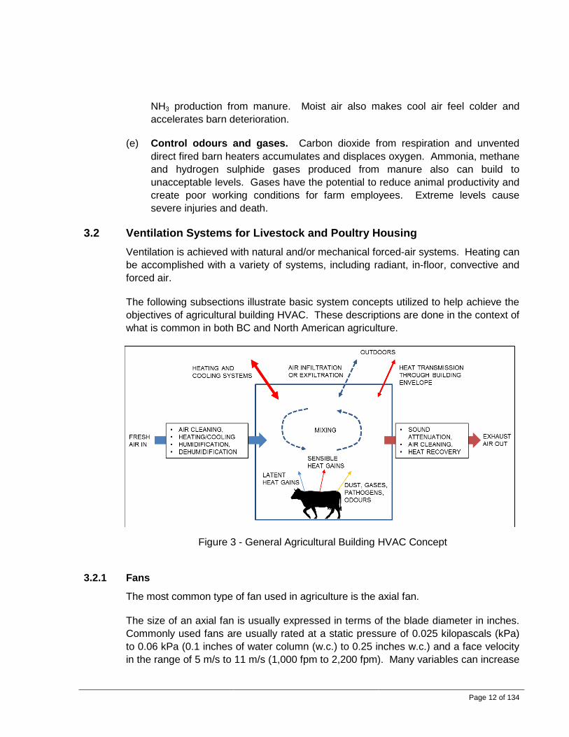
3.2 Ventilation Systems for Livestock and Poultry Housing Ventilation is achieved with natural and/or mechanical forced-air systems. Heating can be accomplished with a variety of systems, including radiant, in-floor, convective and forced air.
The following subsections illustrate basic system concepts utilized to help achieve the objectives of agricultural building HVAC. These descriptions are done in the context of what is common in both BC and North American agriculture.
Figure 3 - General Agricultural Building HVAC Concept
3.2.1 Fans
The most common type of fan used in agriculture is the axial fan.
The size of an axial fan is usually expressed in terms of the blade diameter in inches. Commonly used fans are usually rated at a static pressure of 0.025 kilopascals (kPa) to 0.06 kPa (0.1 inches of water column (w.c.) to 0.25 inches w.c.) and a face velocity in the range of 5 m/s to 11 m/s (1,000 fpm to 2,200 fpm). Many variables can increase

Page 13 of 134
or decrease the air flow rates. For example, chimney fans will typically generate 30% more airflow whereas shutters and wind hoods can result in a 15% decrease. BESS Laboratory at the University of Illinois is a source of independent test data for agricultural ventilation fans. The Air Movement Control Association (AMCA) has standards for fan manufacturers to use in rating the performance of fans.
Table 4 lists some sizes and capacities of commonly used wall exhaust fans.
Table 4 – Common Axial Wall Fan Selections
Nominal Fan Size (blade diameter in inches)
Typical CFM Performance (at 0.10” w.c. static pressure)
10 800 12 1,200 14 1,600 16 2,400 18 3,000 20 3,500 22 4,000 24 5,000 30 7,000 36 10,500 42 14,500 48 20,000 55 22,500 60 25,000 72 38,000
3.2.2 Natural Ventilation
Features and Description: Natural ventilation (NV) systems use large sidewall (and in larger barns, end wall openings) to allow fresh air flow in and out. These sidewall openings are fitted with either a plastic curtain or a moveable insulated wall that can be adjusted incrementally to a more open or closed position to control the overall flow of air. Chimneys or openings along the roof peak are also incorporated, both of which may have adjustable baffles to control the air flow rates. The curtain sidewall can be closed completely during cold or inclement weather to protect the animals. See Figures 4 and 5 below for concept sketches of such systems.

Page 14 of 134
How it works: NV relies on two primary means to ventilate a barn. In the summer, wind is the driver. Even a very small wind can result in a large air exchange rate through the barn when the sidewalls are fully open, necessary to ensure an adequate and comfortable warm weather environment for the animals. Colder weather operation relies on the “chimney” or “stack” effect. As colder weather arrives, the sidewalls are closed gradually. At the same time, a difference in temperature from inside the barn to the outside ambient occurs, the warm moist air in the barn being less dense than the outside air. This difference in density drives the stack or chimney effect. Warm, moist barn air rises to the chimneys and is released at a rate controlled by the adjustable dampers. In cold barns, indoor temperatures are allowed to fluctuate with outdoor temperatures. It is common to have NV systems in cold weather operating with the prevailing wind side curtain fully closed and the leeward side curtain fully open. Ventilation is usually sufficient to maintain indoor temperatures within 3°C to 6°C of outdoor temperatures. Ventilation is largely unregulated, except to adjust for seasonal changes. A cold barn with natural ventilation usually has no insulation, an open ridge and/or eaves, and adjustable sidewall and end wall openings.
Variations: Although ridge vents were historically common, improved controller capabilities and ease of maintenance and management has led to almost all systems using chimney designs. In some cases, fans are added (see Section 3.2.3 regarding Dual Ventilation).
Benefits: These systems have relatively low capital and operating costs. They are quiet and have a limited reliance on power. Emergency generators are usually not necessary or as large. Large air flow rates are possible, especially for barns situated to take advantage of prevailing wind conditions. Using natural ventilation will save energy by reducing the number of ventilation fans needed.
Page 15 of 134
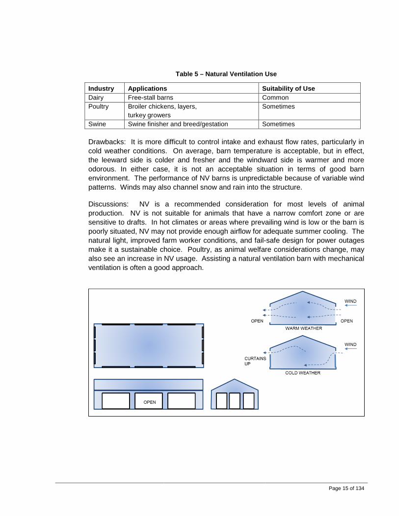
Table 5 – Natural Ventilation Use
Industry Applications Suitability of Use Dairy Free-stall barns Common Poultry Broiler chickens, layers,
turkey growers Sometimes
Swine Swine finisher and breed/gestation Sometimes
Drawbacks: It is more difficult to control intake and exhaust flow rates, particularly in cold weather conditions. On average, barn temperature is acceptable, but in effect, the leeward side is colder and fresher and the windward side is warmer and more odorous. In either case, it is not an acceptable situation in terms of good barn environment. The performance of NV barns is unpredictable because of variable wind patterns. Winds may also channel snow and rain into the structure.
Discussions: NV is a recommended consideration for most levels of animal production. NV is not suitable for animals that have a narrow comfort zone or are sensitive to drafts. In hot climates or areas where prevailing wind is low or the barn is poorly situated, NV may not provide enough airflow for adequate summer cooling. The natural light, improved farm worker conditions, and fail-safe design for power outages make it a sustainable choice. Poultry, as animal welfare considerations change, may also see an increase in NV usage. Assisting a natural ventilation barn with mechanical ventilation is often a good approach.

Page 16 of 134
Figure 4 - Natural Ventilation with Side Walls and End Walls Concept
Figure 5 - Natural Ventilation with Chimneys or Continuous Ridges Concept
3.2.3 Dual Ventilation
Features and Description: Dual Ventilation (DV) systems are a combination of natural and mechanical ventilation, relying on large adjustable wall openings to allow airflow in during warm weather conditions. In colder weather, adjustable inlets in the ceiling plenum or wall allow air to enter which is exhausted with fans. The large wall openings have either a plastic curtain or insulated wall that can be adjusted open or closed to control the overall flow of air. See Figure 6 for a concept sketch.

Page 17 of 134
Figure 6 - Dual Ventilation Concept
How it works: In warm weather, the side wall panels are open, and the barn operates identically to a naturally ventilated barn. Fans are generally not required for summer operation, but in extreme heat or low wind conditions exhaust fans (which can be chimney fans, wall fans or a combination) can be used to increase air flow.
In cold weather, the large side wall openings are closed and exhaust fans operate to maintain minimum ventilation rates. Air is drawn into the building through the air inlets that lead from the attic plenum.
Variations: In some cases the ceiling air inlets are not installed. For cold weather operation, sidewall curtains or panels are adjusted up and down to bring fresh air into the barn. However, improved controller capabilities and ease of maintenance and management has led to almost all systems using inside, ceiling-mounted air inlets.
Benefits: DV systems have much improved air distribution and overall better indoor air quality than an NV-only system in cold weather; there is little difference, however, in warm weather. DV has a low operating cost and limited reliance on power. Emergency generators are usually not necessary (the sidewall panels can be partially opened in cold weather power failure situations) or do not need to be large. Large air flow rates are possible, especially for barns oriented to take advantage of prevailing wind conditions. In the winter, air flow is more uniformly distributed and eliminates the large variations in air quality common with NV-only systems. These systems are usually relatively quiet.
Drawbacks: These systems are more complex than NV-only. Capital and installation costs are similar to NV as the chimney/ridge system is no longer required; however, operating and maintenance costs are higher.
Table 6 – Dual Ventilation Use
Industry Applications Suitability of Use Dairy all rarely Poultry broiler chicken and layers,
turkey grower, sometimes
Swine swine finisher and gestation common
Discussions: Dual ventilation is a recommended consideration for all levels of animal production. The natural light, improved farm worker conditions and fail-safe design for power outages make it a sustainable choice for any type of farm, especially in cooler climates. Poultry, as animal welfare considerations change, may also see an increase in DV usage. Dairy facilities rarely benefit from DV, particularly in the Fraser Valley, as the temperature rarely gets low enough to fully close the curtains.

Page 18 of 134
3.2.4 Exhaust Ventilation Systems
Features and Description: Exhaust Ventilation (Negative Pressure) systems use fans to exhaust air from the barn. An air inlet distribution system allows air flow in. Common concepts are illustrated in Figure 7 and Figure 8.
How it works: As outdoor temperatures increase, a controller will speed up the fans and open the air inlets more. Normally, the fan and inlet changes occur proportionately to inside barn temperature changes. In a cross-flow ventilation system with a slot-type air inlet, the air speed at the animal level ranges from 0.25 to 0.50 m/s (50–100 ft/min).
Figure 7 - Exhaust Ventilation (inlets both sides) System Concept

Page 19 of 134
Figure 8 - Exhaust Ventilation (Cross-Ventilation) System Concept
Benefits: A well-designed system will have excellent year round temperature control and air quality. These systems are very common and are generally the simplest to operate and manage.
Drawbacks: These systems rely on electricity and all facilities should have a standby generator that can be quickly started in the event of power failure. Ignoring important design principles regarding the limitations of the fans and air inlets often results in poor performance.
Variations: The locations of fans (in chimneys or sidewalls) and air inlet design, size and locations vary widely. Inlets can be on one side only for narrow barns or on both sides for wider barns. As shown in Figure 9, a duct system can be used to assist with the distribution of the fresh air. A unit heater can also be used for preheating the fresh air.
Figure 9 - Exhaust Ventilation with Ducted Recirculation System Concept
Table 7 – Exhaust Ventilation Use
Industry Applications Suitability of Use Dairy Calf common Poultry Broiler chickens, layers,
turkey growers common
Swine All common

Page 20 of 134
Discussions: Exhaust ventilation is a fairly broad category. It encompasses many system configurations such as those outlined in Sections 3.2.5 and 3.2.6. This method of ventilation requires continuous monitoring and adjustment to ensure the system is performing as intended. Instruments such as static pressure manometers can be used to help ensure that the building is maintained with a suitable negative pressure. Exhaust ventilation is used in dairy calf barns although it is rarely used in freestall barns unless it is tunnel ventilated for hot weather conditions.
Table 8 lists some common design parameters.
Table 8 – Exhaust Ventilation Common Design Parameters
Parameter Normal Range Air speed at the animal level 0.25 to 0.50 m/s (50 to100 ft/min). Intake air slot width Up to 150 mm (6 inches) Inlet air velocity 3 to 5.1 m/s (600 to 1,000 ft/min) Barn width for cross-ventilation Less than 9.1 to 12 m (30 to 40 ft) wide Barn width for inlets and fans on both sides More than 9.1 to 12 m (30 to 40 ft) wide Air changes Usually target 1 air change per minute in
summer, and 4 air changes per hour in the winter.
Interior barn pressure Usually target -0.01 kPa (-0.04 inches w.c.) in summer and -0.02 kPa (-0.08 inches w.c.) in winter
3.2.5 Tunnel Ventilation
Features and Description: This system configuration is a common variant of the Exhaust Ventilation (Negative Pressure) system. Forced air tunnel ventilation systems typically use axial wall fans, located at one end of a barn, to exhaust air. An air inlet system at the opposite end allows air flow in. Evaporative cooling pads are sometimes located in the air inlets. See Figure 10 for a concept sketch.

Page 21 of 134
Figure 10 – Forced Air Tunnel Ventilation Concept
How it works: In cool conditions, exhaust fans are staged to maintain minimum air exchange rates, with air entering the barn either through attic or sidewall inlets. As the temperature in the barn increases, exhaust fan rates are increased (by activating more fans or increasing fan speed) to provide more cooing. A tunnel ventilated barn will rely on fans to provide ventilation air for the entire year. With tunnel ventilation, there is a high air speed in the barn to enhance the sensible cooling of the animals. High air speed at animal level is essential in hot climates, especially with high humidity levels.
Variations: The locations of fans and inlets can vary. Refer to Figure 11. Tunnel ventilated barns can also be designed to use attic plenum ceiling inlets during cold weather. In some cases, there is not enough available wall area to accommodate the fans or air inlets. In such cases, fans and/or inlets are located on the side of the barn.

Page 22 of 134
Figure 11 – Other Tunnel Ventilation Configurations
Benefits: A well-designed system will have very good cooling performance and can easily incorporate evaporative cooling. Most of the equipment (exhaust fans) is located at one end of the building, thereby reducing costs of maintenance. The capital costs for a power distribution system are also minimized.
Drawbacks: Systems are sometimes mistakenly operated with high ventilation rates when the weather is cold. This creates a cold indoor environment that negatively impacts animal and poultry performance. There are a wide range of design variations being used because few published design standards exist. Consequently, there are many inadequate systems with poor performance. They also use a relatively large amount of electricity on the hottest days of the year, causing a further strain on electrical distribution. These systems are completely reliant on electricity and all facilities require a standby generator that can be quickly started in the event of a power failure. A high-ceiling barn will require a proportionately higher fan capacity to achieve the target air velocity.
Tunnel ventilation is used to achieve a relatively high air velocity throughout the facility to enhance sensible heat loss from the animals. As a result, the dry bulb temperature will increase down the length of the barn. Concentrations of contaminants will also increase along the length of the barn. Tunnel ventilation is not a good option in cold weather because it creates a large temperature, moisture and gas concentration increase between the inlet and the outlet end at low ventilation rates. The air could be 15ºC warmer at the exhaust end of the building and this is usually not tolerable.

Page 23 of 134
Table 9 – Tunnel Ventilation Use
Industry Applications Suitability of Use Dairy All common Poultry Broiler chickens, layers,
turkey growers common
Swine Swine: gestation and finisher common
Discussions: A standard for design, operator training, and well-understood operational strategies would improve overall performance in future installations. Tunnel ventilation is used as a means to provide a “wind chill” cooling effect on poultry and animals. Tunnel ventilation is not recommended to be operated at full flow when the ambient air temperature is below 15°C or for sensitive, younger livestock and chicks because the cooling effect is not necessary.
Table 10 lists some common design parameters.
Table 10 – Tunnel Ventilation Common Design Parameters
Parameter Normal Range Tunnel velocity 1.0–3.0 m/s (200–600 ft/min) Dry bulb temperature increase along length of barn
Up to 2°C (3.6°F) maximum ideally
Air changes Usually target 1 air change per minute in summer, and 4 air changes per hour in the winter.
Interior barn pressure Usually target -0.01 kPa (-0.04 inches w.c.) in summer and -0.02 kPa (-0.08 inches w.c.) in winter
Barn length Usually not more than 100 m (328 ft) from inlet to fan outlet
3.2.6 Pit Ventilation
Features and Description: This system configuration is another variant of the Exhaust Ventilation (Negative Pressure) system. It uses fans to exhaust air from the barn. Buildings with manure storage beneath the floor, often called “deep pit” buildings, generally have concrete annexes in the deep pit wall which are used for pumping manure from the building. These annexes can be used for locating minimum ventilation fans.
How it works: During the winter, the pit fans are usually operated continuously as the first stage for maintaining acceptable humidity and air quality. Pit ventilation is usually less than 30% of the total building ventilation capacity. During the summer, all of the exhaust fans may be staged on to operate and control temperature levels in the barn.

Page 24 of 134
Figure 12 - Attic Inlet Plenum with Pit and Side Wall Exhaust Fans Concept
Variations: Filter boxes can be fitted in the fresh air inlets in the attic.
Benefits: Ventilation of the manure storage pit may reduce indoor odour. Some sort of powered ventilation system must be used in a manure pit if access by personnel is required.
Drawbacks: Pit ventilation may reduce indoor odour but it usually increases odour emissions from the facility. Contaminants are also released to the exhaust air stream during clean-out operations. It is important to note that a manure pit is considered a confined space. Special safety precautions must be followed for safe entry. There is a mistaken belief that all of the gases will be drawn down through the flooring, thereby preventing gases in the manure storage from entering the animal zone. An unrealistically high flow of exhaust air would be required to completely restrict the gases to the pit area. Air velocity through the slats would likely need to be up to 0.75 m/s (150 fpm). Most dairy farmers do not use the slat floor design in favor of other waste handling methods such as scraper or floor flush type systems.
Table 11 – Pit Ventilation Use
Industry Applications Suitability of Use Dairy all Rare Poultry layer Common Swine swine breed, gestation and finisher Sometimes
Table 12 lists some common design parameters.

Page 25 of 134
Table 12 – Pit Ventilation Common Design Parameters
Parameter Normal Range Air flow rates Varies greatly – often sized for up to 36.6 m3/hr
per m2 (2 cfm /ft2) of floor area Dimensions of slats and slots Slat width is up to 152 mm (6") with slot gaps that
are up to 38 mm (1 1/2") wide. Interior barn pressure Usually target -0.01 kPa (-0.04 inches w.c.) in
summer and -0.02 kPa (-0.08 inches w.c.) in winter
3.2.7 Combination Pressure / Exhaust System
Features and Description: This system includes air intake louvers, dampers, recirculation fan(s), air distribution ducting, wall exhaust fans, and unit heaters. Refer to Figure 13.
How it works: A mixture of outdoor air and heated indoor air is drawn into a system of ductwork. The mixed air is delivered throughout the barn. Air is exhausted via the wall exhaust fans.
Figure 13 - Combination Pressure/Exhaust System Concept
Variations: There are many variations of this system available.
Benefits: Mixing is achieved to reduce cold drafts.
Drawbacks: This system is more expensive than conventional forced air systems. The ducting is susceptible to internal fouling.

Page 26 of 134
Table 13 lists some common design parameters.
Table 13 – Combination Pressure/Exhaust Systems Common Design Parameters
Parameter Normal Range Air flow rates Varies greatly Duct velocities Up to 10.1 m/s (2,000 fpm) Interior barn pressure Usually target -0.01 kPa (-0.04 inches w.c.) in
summer and -0.02 kPa (-0.08 inches w.c.) in winter
3.2.8 Neutral Pressure Systems
Features and Description: Neutral pressure systems use a fan or fans to blow air into the barn and a matching fan system to exhaust air out. These fans must increase and decrease speed linearly to avoid creating situations of negative or positive pressure, given that they are not designed to accommodate differential pressures. See Figure 14 for a concept sketch.
How it works: These systems rely on a forced air intake and forced air exhaust fans to provide ventilation air. Ducts are commonly used to distribute the air.
Figure 14 - Forced Air – Neutral Pressure System Concept
Variations: In some situations, two fans are enclosed in one housing system and allow a portion of the intake and exhaust air streams to mix. This creates a benefit in that there is always a tempering effect of the air, minimizing cold drafts.

Page 27 of 134
Benefits: The fresh air can be evenly distributed throughout the barn, and delivered with a higher velocity to provide mixing before the air reaches the animals.
Drawbacks: Neutral pressure systems use relatively large amounts of electricity year round as all the fans need to operate continuously to ensure adequate air distribution. These systems are completely reliant on electrical power and all facilities should have a standby generator that can be quickly started in the event of mains power failure. There are limited numbers of these in use today.
Where it is used: This concept is sometimes used in barns for dairy calf nurseries, swine nurseries, turkey brood, and broiler chickens. This system is rarely used anymore and should not be considered under commercial conditions.
3.2.9 Positive Pressure Ventilation Systems
Features and Description: Positive pressure systems use a fan system to blow air into the barn. Exhaust openings are located throughout the building.
Figure 15 - Distributed Forced Fresh Air with Natural Ventilation
How it works: Each opening usually has a gravity-operated damper to allow air out while maintaining a pressure in the building. See Figure 15 for a concept sketch. These systems rely on forced air intake fans to provide ventilation air into the barn. If heating is required, this is commonly done in the ducting of an air supply system. The configuration shown in Figure 15 is used commonly for young calves that are susceptible to pathogens and odours from adjacent mature cow barns. The fresh air is forced in with a fan and evenly distributed using large ducting with multiple nozzle holes in it. The supply air mixes with inside air throughout the barn. Some exhaust air generally leaks out via manure scraper pits and other openings.

Page 28 of 134
Variations: As shown in Figure 16 and Figure 17, the air can be relieved through the pit area. Positive pressure systems with heated air and distribution ducting are sometimes used in the poultry industry.
Figure 16 - Positive Pressure Ventilation System Concept
Figure 17 - Ducted Positive Pressure System Concept
Benefits: Cold air is introduced uniformly so drafts can be avoided.
Drawbacks: Because the barn is pressurized, the inside air is forced into the building structure through leaks in the building envelope. When the air cools to its dew point, condensation will occur within the building wall cavities. Frost and moisture in the wall

Page 29 of 134
cavities results in the potential for rapid structural deterioration, attics and walls full of wet insulation, and may lead to hidden microbial growth. These systems are also reliant on electricity and all facilities should have a standby generator that can be quickly started in the event of mains power failure. There are very few of these in use today.
Where it is used: This concept is sometimes used in barns for dairy calf nurseries, swine nurseries, turkey brood, and broiler chickens.
Discussions: This system configuration is rarely used anymore and should only be considered for sensitive animals such as dairy or swine nurseries.
Table 14 lists some common design parameters.
Table 14 – Positive Pressure Systems Common Design Parameters
Parameter Normal Range Air flow rates Varies greatly Duct velocities Up to 10.1 m/s (2,000 fpm) Interior barn pressure Up to 0.025 kPa (+0.1 inches w.c.)
3.3 Heating Systems 3.3.1 In-Floor Heating
Features and Description: In-floor heating uses a hot water boiler system to heat hot water. The hot water is then circulated via pumps throughout the barn through pipes that are buried in a grid in the concrete flooring. Floor heat is usually used in farm shops and in livestock housing for creeps or weaner pig areas.
How it works: The hot water warms the concrete to a desired temperature and provides heat to warm the entire barn. See Figure 18 as a conceptual example for a poultry broiler facility.

Page 30 of 134
Figure 18 - In-Floor Heating Concept
Variations: Spot heating is sometimes used for swine. The piglet resting section can be quite small in the farrowing crate creep area. A heated floor in this area provides a comfortable warm microclimate for the nursing piglets. Another system variation is to use in-floor cooling systems. In-floor cooling is generally not recommended because it results in increased moisture levels on the floor.
Benefits: Some claim that these systems have lower operating costs. It is an excellent method to distribute large amounts of heat in a large scale operation. Only one heat source (the hot water boiler(s)) is needed which is more manageable. Hydronic floor heating reduces energy consumption because it produces a microclimate near the floor where the animals are located rather than heating the whole volume of air in the building.
Drawbacks: The thermal flywheel effect is very difficult to overcome. For example, as nights cool off, the demand for heat can rise rapidly; but the time required to heat the concrete mass can result in lower-than-desired temperatures. Conversely, once the concrete floor is warm, it can take several hours to cool down, again resulting in uncomfortable conditions. This is a costly system considering its disadvantages. A carefully designed system with external temperature (outdoor) reset control can overcome some but not all of the thermal flywheel effect issues.

Page 31 of 134
Table 15 – In-Floor Heating Systems Use
Industry Applications Suitability of Use Dairy calf, milk houses, milk parlours sometimes Poultry broiler chickens rare Swine farrowing crate creeps, nursery, under stalls
in gestation barns sometimes
Table 16 lists some common design parameters.
Table 16 – In-floor Heating Systems Common Design Parameters Parameter Normal Range Floor temperature 22 to 32°C (72 to 90°F) Water temperature drop 5 to 8°C (9 to 15°F) Water temperature Up to 15°C (27°F) warmer than floor slab Heat output per unit floor area Up to 300 W/m2 (95 BTU/hr per ft2) Heat flow 0.07 kW per L/min flow per 1°C temperature change
500 BTU/hr per 1 gpm flow per 1°F temperature change Pipe velocity Up to 3 m/s (10 ft/s)
3.3.2 Gas-Fired Radiant Heating
Features and Description: Gas-fired radiant heaters are designed to heat a designated surface area in a barn to a comfortable temperature. In many cases, the non-radiant heated areas are cooler by design.
How it works: Heated tubes radiate heat downwards towards the designated animal housing area. This heat in turn heats the surfaces it strikes much like the sun warms the earth, rather than the air itself. See Figure 19. By carefully designing the size and locations of the heaters, fresh air can be pre-warmed and the primary livestock/poultry resting areas can be kept warm, dry and comfortable.

Page 32 of 134
Figure 19 - Gas-Fired Radiant Heating Concept
Variations: There are a number of radiant fired heaters with variable and two-stage outputs to more closely match animal housing needs. These heaters can either vent toward the outside or within the barn.
Benefits: Operating costs are relatively low as the heat is being applied directly to the animals. Gas-fired radiant heaters have a very good thermal response and create limited thermal flywheel impacts. They are also easier to operate and less costly to install than in-floor heating. Radiant heaters can be used to heat large areas. They warm the animals and objects in the building without directly heating the air. This reduces heating requirements.
Drawbacks: Gas-fired radiant heaters are more costly than forced-air direct-fired unvented unit heaters. Any system that vents products of combustion directly to the occupied space increases moisture, CO2 and other contaminants into the building.
A supply of natural gas or propane is required.
Table 17 – Gas-Fired Radiant Heating Use
Industry Applications Suitability of Use Dairy Calf, dairy with cold climates sometimes Poultry Turkey brood and grow, and broiler chicken rare Swine Nursery, high-ceiling gestation barns sometimes
Table 18 lists some common design parameters.

Page 33 of 134
Table 18 – Gas-Fired Radiant Heating Common Design Parameters
Parameter Normal Range Tube heater diameter 100 mm (4 inch) Tube heater length 6.1 to 18.3 m ( 20 to 60 feet) Tube temperature Up to 650°C (1200°F) Capacity per heater 7.3 to 73 kW (25,000 to 250,000 BTU/hr)
3.3.3 Convective Heating
Features and Description: Convective heaters consist of a passive heat source, most commonly as hot water fin pipe or straight pipe that is not finned at all. See Figure 20.
Figure 20 - Convective Heating Concept
How it works: This concept is commonly used in areas of a barn where higher heat levels are needed during extended cold periods when outdoor temperatures are usually colder than -10°C. The heat source (hot water pipe shown in the figure) is located strategically close to the fresh air supply to pre-warm the cold air as it enters the barn. This results in improved air distribution and prevents the cold air from creating drafts. Careful sizing of the pipe diameter, lengths of pipes and use of mixing valves, circulating pumps, backflow valves and a modulating heat output on the controller are essential elements in optimizing the performance of a hot water system and in maintaining the barn at a comfortable temperature.
Variations: There are convective heaters which rely solely on electricity for generating heat, but due to the relatively high cost per energy unit of electrical power compared to fossil fuels, they are rarely used anymore.

Page 34 of 134
Benefits: Hot water (hydronic) heating is an effective method of moving large amounts of heat within a barn, since water has four times the thermal capacity of air.
Drawbacks: Hot water systems have a relatively higher initial installation cost. Higher costs and the increased need for top quality controls and proper controls settings are essential. There is a slower thermal response than exists with other heating systems, thus creating a thermal flywheel issue. In turn, barns can cool off more than desired, take longer to heat up, and take longer to cool down once warmer weather returns. The system is difficult to modify or expand once it has been installed. While this is a very effective system for the types of operations mentioned, the overall complexity and need for a well-designed layout and well-operated management makes them less attractive for temperate climates such as the Fraser Valley.
Table 19 – Convective Heating Use
Industry Applications Suitability of Use Dairy calf sometimes Poultry turkey brood and grow, and broiler chicken sometimes Swine nursery, finishing, gestation sometimes
Table 20 lists some common design parameters.
Table 20 – Convective Heating Systems Common Design Parameters
Parameter Normal Range Water temperature Up to 93°C (200°F) Water temperature drop Up to 20°C (36°F) Heat flow 0.07 kW per L/min flow per 1°C temperature change
500 BTU/hr per 1 gpm flow per 1°F temperature change Pipe velocity Up to 3 m/s (10 ft/s)
3.3.4 Unit Heaters
Features and Description: As shown in Figure 21, a forced air unit heater is equipped with a fan and a heater to circulate heated air throughout the barn. Forced air heat is the most common heat system in North American agriculture.
How it works: For gas-fired systems, the burner is located inside the housing with a fan. The fan draws barn air in, propane or natural gas is burned, and the hot gases are vented directly into the barn.
Variations: Gas heaters can be wall mounted on the outside of the barn to draw in outside air instead of barn air. Typically, the by-products of combustion are still vented directly into the barn. The unit heater can also use hot water, steam or electric coils

Page 35 of 134
which eliminate having combustion air being vented directly into the barn space. Unit heaters may also be indirectly fired, with products of combustion vented directly outside.
Figure 21 - Unit Heaters Concept
Benefits: These heaters are generally low in cost. They have very good thermal response and create limited thermal flywheel impacts. They are also easier and less costly to install than other heating systems. By careful sizing and proper location of heaters, the barn air can be kept at a comfortable temperature.
Drawbacks: They are not as effective as infrared heaters and result in higher operating costs. Gas-fired forced-air heaters use barn air, thereby lowering the available oxygen. In addition, they release the by-products of combustion directly into the air space. This in turn increases the CO2 and moisture loading ultimately leading to higher required air exchange rates.
Table 21 – Unit Heaters Use
Industry Applications Suitability of Use Dairy calf sometimes Poultry turkey brood and grow, and broiler chicken sometimes Swine farrow, nursery, finishing, breed/gestation sometimes
Table 22 lists some common design parameters.
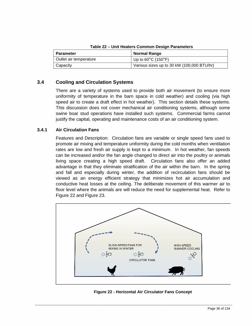
Page 36 of 134
Table 22 – Unit Heaters Common Design Parameters Parameter Normal Range Outlet air temperature Up to 60°C (150°F) Capacity Various sizes up to 30 kW (100,000 BTU/hr)
3.4 Cooling and Circulation Systems There are a variety of systems used to provide both air movement (to ensure more uniformity of temperature in the barn space in cold weather) and cooling (via high speed air to create a draft effect in hot weather). This section details these systems. This discussion does not cover mechanical air conditioning systems, although some swine boar stud operations have installed such systems. Commercial farms cannot justify the capital, operating and maintenance costs of an air conditioning system.
3.4.1 Air Circulation Fans
Features and Description: Circulation fans are variable or single speed fans used to promote air mixing and temperature uniformity during the cold months when ventilation rates are low and fresh air supply is kept to a minimum. In hot weather, fan speeds can be increased and/or the fan angle changed to direct air into the poultry or animals living space creating a high speed draft. Circulation fans also offer an added advantage in that they eliminate stratification of the air within the barn. In the spring and fall and especially during winter, the addition of recirculation fans should be viewed as an energy efficient strategy that minimizes hot air accumulation and conductive heat losses at the ceiling. The deliberate movement of this warmer air to floor level where the animals are will reduce the need for supplemental heat. Refer to Figure 22 and Figure 23.
Figure 22 - Horizontal Air Circulator Fans Concept
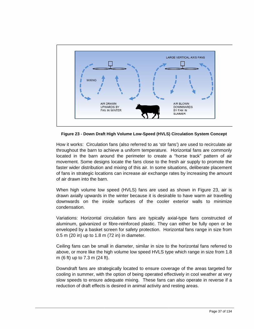
Page 37 of 134
Figure 23 - Down Draft High Volume Low-Speed (HVLS) Circulation System Concept
How it works: Circulation fans (also referred to as ‘stir fans’) are used to recirculate air throughout the barn to achieve a uniform temperature. Horizontal fans are commonly located in the barn around the perimeter to create a “horse track” pattern of air movement. Some designs locate the fans close to the fresh air supply to promote the faster wider distribution and mixing of this air. In some situations, deliberate placement of fans in strategic locations can increase air exchange rates by increasing the amount of air drawn into the barn.
When high volume low speed (HVLS) fans are used as shown in Figure 23, air is drawn axially upwards in the winter because it is desirable to have warm air travelling downwards on the inside surfaces of the cooler exterior walls to minimize condensation.
Variations: Horizontal circulation fans are typically axial-type fans constructed of aluminum, galvanized or fibre-reinforced plastic. They can either be fully open or be enveloped by a basket screen for safety protection. Horizontal fans range in size from 0.5 m (20 in) up to 1.8 m (72 in) in diameter.
Ceiling fans can be small in diameter, similar in size to the horizontal fans referred to above, or more like the high volume low speed HVLS type which range in size from 1.8 m (6 ft) up to 7.3 m (24 ft).
Downdraft fans are strategically located to ensure coverage of the areas targeted for cooling in summer, with the option of being operated effectively in cool weather at very slow speeds to ensure adequate mixing. These fans can also operate in reverse if a reduction of draft effects is desired in animal activity and resting areas.

Page 38 of 134
Benefits: The primary benefits of recirculation systems include reduced heating costs, a more comfortable environment, improved air distribution, and destratification. They can also be added to existing barns easily to improve air distribution and cooling. Noise levels associated with HVLS fans are minimal.
Drawbacks: Care in the design and operation is essential to prevent unwanted drafts in cooler weather. Undesired air movement at animal level are possible if the fans are poorly placed. Existing barn structures and equipment may limit proper fan placement. Although horizontal circulation fans are sometimes marketed as improving air exchange rates, circulation fans typically do not significantly increase air exchange rates.
Table 23 – Horizontal and Small Diameter Vertical Fan Use
Industry Applications Suitability of Use Dairy all common Poultry broiler chicken, and layers
turkey brood/grower, sometimes
Swine finisher, breed/gestation sometimes
Table 24 – HVLS Fan Use
Industry Applications Suitability of Use Dairy all common Poultry turkey grower and broiler chicken. sometimes Swine finisher, breed/gestation sometimes
Discussions: Circulation systems are an effective method of optimizing the cold weather indoor environment and also providing a cooling effect for hot weather conditions. Circulation fans are not required in a tunnel ventilated barn in warm months because there are limited stagnant air pockets in such systems; however, in the winter circulation fans may be required to direct warm air down to animal level.
Table 25 lists some common design parameters.

Page 39 of 134
Table 25 – Air Circulation Fans Common Design Parameters
Parameter Normal Range Circulator fan air velocity Up to 2.5 m/s (500 fpm) air velocity on a cow Circulator fan air flow rates 36 inch fan: 3 to 6.1 m3/s (6,400 to 13,000 cfm)
48 inch fan: 6.7 to 10.8 m3/s (14,100 to 23,000 cfm)
Circulator fan angle
Angled downward 15 to 30° (aim towards floor below next fan)
Circulator fan height above floor for cows
Up to 2.4 m (8 ft)
Horizontal air circulation fan size 0.5 m to 1.8 m (20 to 72 in) diameter High Volume Low Speed HVLS vertical circulation fan size
1.8 m to 7.3 m (6 ft to 24 ft) diameter
Air velocity at animal level Up to 3 m/s (600 fpm)
3.4.2 Ducted Recirculation Systems
Features and Description: Ducted recirculation fan systems commonly use a variable speed fan to mix and recirculate barn air via a designed duct system. They are used to promote air mixing and temperature uniformity during the cold months when ventilation rates are low and fresh air supply is minimized to save on heating costs. They also can be located below an air inlet distribution system to prevent drafts and promote proper air patterns and air flow in the barn space. Ducted systems can also offer an added advantage in that they assist in the destratification of air within the barn. In the spring and fall and especially during winter, the addition of ducts should be viewed as an energy efficient strategy that minimizes warm air accumulation and conductive heat losses at the ceiling. The deliberate movement of this warm air to the floor level where the animals are will reduce the need for supplemental heat. See Figure 24 for a concept sketch.

Page 40 of 134
Figure 24 - Ducted Recirculation System Concept
How it works: The fan draws barn air in and vents it out via small-diameter holes within the duct; the holes can be on both sides or on one side only. Correct hole diameter is essential to achieve the desired air flow and throw. Some designs locate the ducts close to a fresh air supply to promote mixing with the warm recirculation air.
Variations: The ducts can be located near the ceiling and are typically constructed of plywood, polyvinyl chloride (PVC) or polyethylene. Fans can be located in the center or at one end and integrated with forced air heater systems to distribute heated air as well.
Benefits: The primary benefits of ducted recirculation systems include a more comfortable environment, improved air distribution and destratification. They can also intercept cold air drafts from fresh air inlets that are leaking and/or improperly adjusted.
Drawbacks: Proper design and location are essential but commonly incorrectly done. The issue of dust and pathogen accumulation and the difficulty in cleaning and sterilizing is making these systems less popular.
Table 26 – Ducted Recirculation System Use
Industry Applications Suitability of Use Dairy calf sometimes Poultry turkey brood and grow, and broiler chicken sometimes Swine farrow, nursery, finishing, breed/gestation sometimes
Table 27 lists some common design parameters.

Page 41 of 134
Table 27 – Ducted Recirculation System Common Design Parameters
Parameter Normal Range Air flow rates Varies greatly Duct velocities Up to 10.1 m/s (2,000 fpm) Air flow rates Varies greatly
3.4.3 Cooling with Low-Pressure Water Sprinklers or Drippers
Features and Description: Low pressure water cooling systems rely on water falling as larger droplets on an animal or bird in dedicated areas of the barn. The distribution systems vary widely and in all cases must be integrated with the feed and animal/bird resting locations. Low-pressure sprinkler systems wet the animal’s body with a brief shower followed by a non-sprinkling period. During the non-sprinkling period the animal body heat is used to evaporate the water from the skin and hair coat. This evaporation provides a cooling effect as does an animal’s natural sweating response during warm weather. It is the same cooling feeling people experience coming out of a shower or swimming pool. It is critical to have a non-sprinkling period to allow time for the water to evaporate from the skin surface. The evaporative cooling effect is more efficient when the sprinklers are intermittent.
See Figure 25 for a concept sketch.
Figure 25 - Cooling with Low-Pressure Water Sprinklers or Drippers
How it works: Low-pressure nozzles produce large droplets that soak the surfaces they are deposited on. Water lines need to be sized and sprinklers need to be located at suitable intervals to provide adequate water flow for uniform distribution along a supply pipe or across a holding area. A controller that initiates the sprinkler is

Page 42 of 134
triggered by an increase in barn temperature. The controller also has an adjustable timer to allow the sprinkler to operate only for a limited time period. This allows the water a chance to evaporate from an animal’s skin, fur, or feathers, and in the evaporation process, removes core body heat.
Variations: The controller can incorporate multiple stages and allow increased shower duration as the barn gets warmer. In swine barns, these sprinklers are used in encouraging proper dunging behaviours in swine, in addition to pre-soaking the entire room prior to cleaning and disinfection. Some poultry facilities have also used the sprinklers to assist with medication distribution. Another approach for achieving localized cooling is a chilled water bed. While not a common practice, dairy cows, for example, can be provided beds that have chilled water circulating through them to help maintain their body temperature.
Benefits: The primary benefits of low pressure sprinkling include a more comfortable environment, improved performance, and in some cases, dust and odour reduction. These cooling systems are very low cost and easy to manage.
Drawbacks: Proper design and location are essential. Excessive sprinkling wastes water and adds unnecessary water to the manure system. A water flow meter and anti-drip features are critical in preventing flooding and excessive water use. The addition of water without the use of ventilation fans will lead to increased humidity and heat stress in holding pens. Fans in sprinklered systems may be susceptible to fouling and may need to be cleaned frequently.
Table 28 – Low-Pressure Water Sprinklers or Drippers Use
Industry Applications Suitability of Use Dairy Parlour exit, exit alley, exit platform, feed
line, holding pens common
Poultry turkey brood and grow, and broiler chicken common Swine farrow, breed/gestation common
Discussions: Sprinkler cooling systems should be considered essential for many barns and can be installed for a relatively low cost. Sprinklers are rarely used in BC to cool poultry; however, they perform equally well compared to evaporative cooling pads in both reducing mortality and increasing weight gain feed efficiency. Sprinklers are more effective than fans over feed lane areas for dairy whereas fans are more suitable than sprinklers over free stalls to ensure that they remain dry. Application of water with low-pressure sprinklers cools cows more efficiently than is the case if fans are used alone.
Table 29 lists some common design parameters.

Page 43 of 134
Table 29 – Low-Pressure Water Sprinklers or Drippers Common Design Parameters
Parameter Normal Range Low-pressure systems water pressure 138 to 276 kPa (20 to 40 psi) Low-pressure system nozzle water flow
1.9 to 3.8 litres per minute (0.5 to 1.0 gpm)
3.4.4 Evaporative Cooling with Direct High–Pressure Misting
Features and Description: High-pressure misting systems are sometimes called fogging systems. They produce very fine water droplets that are discharged into the barn fresh supply air. As the water droplets evaporate, they absorb energy which lowers the air temperature. The cooler air temperature helps the animal and bird lose body heat more readily.
See Figure 26 for a concept sketch.
Figure 26 - Evaporative Cooling with Direct High–Pressure Misting Concept
How it works: High-pressure systems operate with water pressures up to 7000 kPa (about 1000 psi). Since most barns normally have a water supply system that typically operates at near 350 kPa (about 50 psi), a booster pump is required. Because high pressures and small orifices produce small water droplets, high-pressure system nozzles can be attached to fans that direct the mist above animal feeding and traffic areas. Alternatively, they can be located in the inlet side of a cross-ventilated barn to create a cooling effect before the air reaches the animals. High-pressure systems require clean water and in-line filters to minimize plugging of the nozzles.
Water lines need to be constructed of stainless steel or high-pressure hose and sized to provide adequate water flow for uniform distribution across the air inlet or
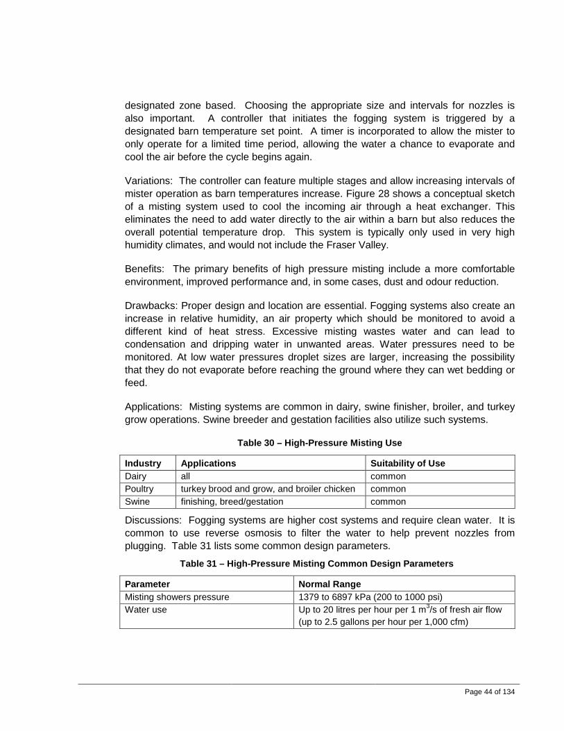
Page 44 of 134
designated zone based. Choosing the appropriate size and intervals for nozzles is also important. A controller that initiates the fogging system is triggered by a designated barn temperature set point. A timer is incorporated to allow the mister to only operate for a limited time period, allowing the water a chance to evaporate and cool the air before the cycle begins again.
Variations: The controller can feature multiple stages and allow increasing intervals of mister operation as barn temperatures increase. Figure 28 shows a conceptual sketch of a misting system used to cool the incoming air through a heat exchanger. This eliminates the need to add water directly to the air within a barn but also reduces the overall potential temperature drop. This system is typically only used in very high humidity climates, and would not include the Fraser Valley.
Benefits: The primary benefits of high pressure misting include a more comfortable environment, improved performance and, in some cases, dust and odour reduction.
Drawbacks: Proper design and location are essential. Fogging systems also create an increase in relative humidity, an air property which should be monitored to avoid a different kind of heat stress. Excessive misting wastes water and can lead to condensation and dripping water in unwanted areas. Water pressures need to be monitored. At low water pressures droplet sizes are larger, increasing the possibility that they do not evaporate before reaching the ground where they can wet bedding or feed.
Applications: Misting systems are common in dairy, swine finisher, broiler, and turkey grow operations. Swine breeder and gestation facilities also utilize such systems.
Table 30 – High-Pressure Misting Use
Industry Applications Suitability of Use Dairy all common Poultry turkey brood and grow, and broiler chicken common Swine finishing, breed/gestation common
Discussions: Fogging systems are higher cost systems and require clean water. It is common to use reverse osmosis to filter the water to help prevent nozzles from plugging. Table 31 lists some common design parameters.
Table 31 – High-Pressure Misting Common Design Parameters
Parameter Normal Range Misting showers pressure 1379 to 6897 kPa (200 to 1000 psi) Water use Up to 20 litres per hour per 1 m3/s of fresh air flow
(up to 2.5 gallons per hour per 1,000 cfm)

Page 45 of 134
3.4.5 Evaporative Cooling Pads
Features and Description: See Figure 27 for a conceptual sketch. This is often referred to as a ”swamp cooler”. The evaporative cooling pad is made of fibrous material with large gaps to minimize air pressure drop. The pad is mounted vertically over the building air intake. The bottom of the pad rests in a drain trough, and a water distribution pipe with evenly spaced holes runs across the top of the pad. A circulating pump is used to transfer the water from the trough to the distribution pipe at the top of the pad.
Figure 27 – Direct Evaporative Cooling with Media Concept
How it works: Outdoor air is drawn through evaporation media. Within the media, some of the water evaporates, extracting heat from the air and lowering the temperature. The amount of air temperature drop depends on many factors, including the outside temperature, the relative humidity, and the pad’s effectiveness. The dryer the climate the better the evaporative cooling rate. Reductions of as much as 20°F (11°C) are possible, but 10°F (6°C) is more typical in more humid climates such as the Fraser Valley. A controller that initiates the water flow is triggered by an increase in barn temperature. When evaporative cooling is needed, the controller activates the pump, which delivers water to the distribution pipe that trickles water down the face of the pad to wet it.
Fresh water is added to the system via a float mechanism to replenish the water that is evaporated within the air stream during the ventilation process.
Variations: Locations of the cooling pads are dependent on air inlet locations.
Benefits: The primary benefits of evaporative pad cooling systems include a more comfortable environment, improved performance and in some cases, dust and odour

Page 46 of 134
reduction. Lower mortalities and higher weight gain and feed efficiency are an added benefit in hot weather. Operating costs are low if used in tunnel ventilated barns.
Drawbacks: Proper design and location are essential. Evaporative pad systems also create an increase in relative humidity, an air property which should be monitored to avoid a different kind of heat stress. Evaporative cooling systems and pads require regular maintenance to minimize algal growth and accumulation of dirt and minerals on the pads and in the water. Some suppliers do not recommend using them because of these risks and disadvantages. Evaporative pads generally require higher water consumption than comparable low pressure sprinklered barn systems. Pad systems are relatively high in cost and require regular maintenance. Winterizing requires draining the water supply system and covering the air inlet.
Applications: Evaporative cooling pads are used almost exclusively with tunnel ventilated barns. They can, however, be integrated into cross-ventilated facilities. They have also been used successfully in mechanically ventilated poultry, swine and turkey buildings. In regions with high temperatures and high humidity levels such as the southern United States, evaporative cooling pads are frequently used in poultry housing. The use of high-pressure misting nozzles is, however, preferred.
Table 32 – Evaporative Cooling Pad Use
Industry Applications Suitability of Use Dairy all rare Poultry turkey brood and grow, and broiler chicken common Swine finishing, breed/gestation rare
Table 33 lists some common design parameters.
Table 33 – Evaporative Cooling Pads Common Design Parameters
Parameter Normal Range Face Velocity 1.65 to 2.03 m/s (325 to 400 fpm) Head loss Up to 0.02 kPa (0.08 inches w.c.) Dry bulb reduction 6 to 11°C (10 to 20°F) Water use Up to 20 litres per hour per 1 m3/s of air flow
(up to 2.5 gallons per hour per 1,000 cfm)
Table 34 includes some sample performances of evaporative cooling for various regions of BC. The July design temperature and humidity for each of the selected locations are used. The flow rate of water being evaporated is calculated based on increasing the relative humidity to 60%. The water flow rates are based on an inlet air

Page 47 of 134
flow rate of 50 m3/s (about 106,000 cfm). The hottest day on record for Abbotsford is included for comparison purposes.
Table 34 – Example Evaporative Cooling Performances
Location Outdoor Air Cooled Air into Barn *Latent Cooling kW
*Water Flow litres per
hour Dry Bulb °C
Wet Bulb °C
RH Dry Bulb °C
Wet Bulb °C
RH
Nanaimo (10m ASL) 26 18 45% 23 18 60% 166 240
Abbotsford (10m ASL) 29 20 42% 25 20 60% 215 310
Abbotsford (10m ASL) Hottest on record
38 23 25% 28 23 60% 535 770
Kelowna (350m ASL) 33 20 28% 25 20 60% 428 620
Castlegar (430m ASL) 32 20 30% 25 19 60% 387 560
Williams Lake (615m ASL) 29 17 28% 22 17 60% 387 560
Terrace (60m ASL) 25 16 38% 21 16 60% 242 350
Smithers (500m ASL) 25 17 44% 22 17 60% 166 240
Fort St. John (685m ASL) 26 18 45%
23 18 60% 159 230
* The latent cooling rates and water flow rates are based on an inlet air flow of 50 m3/s (105,944 cfm)
3.4.6 Evaporative Cooling in Forced Air Systems – Indirect
Features and Description: Indirect evaporative cooling uses a heat exchanger to cool the supply air to the barn. See Figure 28 for a concept sketch.

Page 48 of 134
Figure 28 - Evaporative Cooling in Forced Air Systems – Indirect – Concept
How it works: Outdoor air is drawn through a heat exchanger. The fresh air is cooled with a secondary air stream. This secondary air stream is outdoor air that is cooled using high-pressure misting showers. The showers evaporate into the airstream and cause the air temperature to decrease adiabatically. The fresh air being drawn into the building does not become humidified; it is only cooled. The secondary airstream is humidified as the evaporative cooling takes place, but it is released to the outdoors. It is only used to cool the air that is drawn into the building. The dryer the climate is, the better is the evaporative cooling rate that can be achieved. Reductions of as much as 20°F (11°C) are possible, but 10°F (6°C) is normal in more humid climates such as the Fraser Valley. A controller that initiates the water flow is triggered by an increase in barn temperature.
Variations: Additional cooling can be achieved by adding high pressure misting showers directly to the cooled supply air.
Benefits: No moisture is added to the fresh air that enters the building. This is beneficial in hot humid climates because there is no reduction in the evaporative cooling capacity of the animals’ bodies while at the same time being able to achieve increased sensible heat losses due to the lower barn temperatures.
Drawbacks: Evaporative cooling systems require regular maintenance to minimize algal growth and accumulation of dirt and minerals in the heat exchanger and ducting. This type of system is more expensive than direct evaporative coolers, both in capital and operating costs.
Applications: This type of system is typically used in humid climates where additional moisture in the barn is unacceptable. They are typically not a suitable option in BC.

Page 49 of 134
3.5 Heat Recovery and Alternatives 3.5.1 Air-to-Air Heat Recovery
Features and Description: Air-to-air heat exchangers use the exhaust heat from the barn to preheat the cold intake air. See Figure 29 for a concept sketch.
Figure 29 - Air to Air Heat Recovery Concept
How it works: Exhaust air is laden with dust, odours and moisture. The heat in the air (called sensible heat) and the moisture in the air (called latent heat) can be transferred via a heat exchanger to preheat the cold incoming air. Because the two air streams are separated by a metal or plastic plate, none of the odours or moisture are transferred to the fresh incoming air. Filtration is typically required upstream of the heat exchanger to minimize fouling.
Variations: Heat exchangers come in a variety of types. The most common types are configured as plates or shells and tubes.
Benefits: The use of heat recovery systems results in lower operating costs.
Drawbacks: Due to the foul exhaust air, cleaning of animal housing heat exchangers is a challenge. These are higher cost systems and require regular maintenance. Air-to-air heat exchangers also require all exhaust air to be vented to one location unless multiple heat exchangers are placed, in which case the incorporation of such systems is usually not economically viable. Also, all fresh air is supplied at one location. As a result, ducting and a more sophisticated air handling is required. This in turn creates added capital costs and management and maintenance issues.
Application: Heat exchangers have been used successfully in calf barns, swine farrowing facilities, swine nurseries and poultry brooder barns

Page 50 of 134
Table 35 – Air to Air Heat-Recovery Use
Industry Applications Suitability of Use Dairy Calf Sometimes Poultry Brooder Sometimes Swine Farrow and nursery Sometimes
Discussions: Heat recovery should always be considered as a potential energy savings practice in facilities. The colder the climate and the higher a required animal housing target temperature is, the better the economics that are realizable. Fraser Valley climatic conditions make these systems more difficult to justify.
3.5.2 Thermal Capacitance of Buildings
Features and Description: A building is constructed with high thermal mass to minimize the adverse effects of temperature swings that occur in a 24 hour period.
How it works: An important concept to understand is the effect of thermal capacitance. It is often referred to as the ‘thermal flywheel’ effect. It is the ability of the building components of a barn (concrete floors, walls, ceiling and equipment) to store thermal energy, providing “inertia” to dampen temperature changes. Systems which heat the animals directly can react faster to thermal flywheel effects. A building that is constructed of high density materials such as concrete tends to store large amounts of heat energy. This reduces or dampens the effects of large outdoor temperature swings.
Figure 30 - Building Thermal Capacitance Concept

Page 51 of 134
Variations: This is a general concept description and there are many possible variations, such as utilizing thermal masses in barns such as hallways and storage rooms.
Benefits: The primary benefit of incorporating thermal mass into a building is that lower operating costs are achievable. The thermal mass shaves the peaks off heating and cooling loads that occur throughout the day, thereby lowering heating and cooling capacity needs.
Drawbacks: Increased building mass may equate to increased construction costs.
3.5.3 External Thermal Capacitance
Where it is used: This concept can be used to both preheat air in cold weather and to cool it in hot weather.
Figure 31 - External Thermal Capacitance Concept
Features and Description: A supply fan draws air through a large chamber that holds a large amount of dense material such as rocks, concrete blocks, or steel.
How it works: The air being supplied to the building is drawn through a large thermal mass. Since the outside ambient air temperature varies from day to night, the incoming fresh air either releases heat during the day or absorbs heat during the night in cold weather time periods. As a result, the outgoing fresh air entering the barn tends to be at a more uniform temperature during a 24 hour period.
Variations: If the supply fan is intermittently reversed, the thermal mass may be intermittently heated with building exhaust air. Such variations have been tested in the

Page 52 of 134
past and shown to generate benefits, but the thermal mass has been found to be susceptible to fouling and microbial growth. Another variation is to use a large tank of water and an air to water heat exchanger.
Benefits: Incorporating external thermal capacity into a building design will result in lower operating costs. The thermal mass shaves the peaks off heating and cooling loads, thereby lowering heating and cooling needs.
Drawbacks: Cost may be an issue. Algal growth and accumulation of dirt and minerals may be an issue.
Discussion: This concept will require some research and demonstration in the future to prove viability.
3.5.4 Earth Tube System
Features and Description: Conventional thin-walled plastic sewer drain vent pipes or culverts are buried underground. A sump is provided for drainage. A supply fan draws the air through the tubes and delivers it to the conditioned space.
How it works: Filtered fresh air enters a series of buried non-porous pipes outside of the building. Outside air with its seasonal varying temperatures is drawn down through relatively constant earth temperatures at 1.5 m to 3 m below grade. The fresh air is heated or cooled by the earth depending on the relative temperature between the outside air and the ground temperature. Heat energy is transferred between the air and the surrounding soil, moderating the barn inlet temperature of the fresh air. The longer the earth tube is, the closer will be the air temperature to the earth temperature. In the hot summer, the heat in the outdoor air is transferred to the earth, resulting in cooler building supply air temperatures. In the winter, heat from the earth is absorbed into the cooler incoming air, resulting in warmer supply air temperatures. The differences between temperatures below and above ground change with the seasons. In winter, ground temperatures are warmer than the outdoor air while in summer ground temperatures are cooler than the outdoor air. These temperature differences make earth tube systems potentially beneficial and attractive from an energy conservation perspective.

Page 53 of 134
Figure 32 - Earth Tube System Concept
Variations: In some cases it may be possible to design the system to generate natural convection through the earth tubes to create a passive geothermal system that supplements a high thermal mass building’s heating and cooling system.
Benefits: Earth tubes generally result in lower operating costs. Earth tube heat exchangers shave the peaks off heating and cooling loads that occur throughout the day, thereby lowering heating and cooling capacity needs.
Drawbacks: Earth tubes do not work well in hot humid climates without some form of dehumidification to prevent water from condensing in the earth tubes. To counter this disadvantage, a sloped tube system to a sump pump area to collect and remove condensate is easier and less costly to incorporate than a dehumidifier. Problems may occur if the pipes are not watertight. While high ground water levels may be beneficial to overall system performance, flooding in the network of leaking pipes will not allow the passage of air. Concrete is not usually suitable for buried tubes because they are difficult to clean.
Discussions: These systems have been in use since the mid-1980s and have had a good degree of success. The best time to install these is during barn construction as there will already be excavation in progress. Dense wet soil is very conductive and preferable over dry sandy soil.
Table 36 lists some common design parameters.

Page 54 of 134
Table 36 – Earth Tube Systems Common Design Parameters
Parameter Normal Range Depth of ventilation tubes in ground 1.5 to 3 m (5ft to 10ft) Air velocity in underground tubes 6 to 10 m/s (1,180 to 1,970 fpm) Tube materials Metal, plastics, sometimes concrete Earth temperature below frost-line Usually 10 to 16°C (50 to 61°F), depending on
location and time of year
3.5.5 Transpired Solar Walls
Figure 33 - Transpired Solar Wall Concept
Where it is used: Transpired solar walls have been used in agricultural, industrial, and commercial buildings in North America and Europe.
Features and Description: The transpired wall consists of a dark-colored porous metal wall that is placed on the sunny side the building, outside of the building wall. A plenum space exists between the building wall and perforated wall panel.
How it works: The perforated transpired wall panel is heated by the sun. Air is heated as it is drawn through the small holes in the perforated transpired wall. During brooding or in winter, when the minimum or mild weather fans are activated, air is drawn through the minute holes in the transpired wall and is heated up. In the northern hemisphere, most of the sunlight is incident on the south side during winter. The solar collector is located adjacent to the length of the barn and should therefore face true south. It can face up to 30° either way from true south but there will be a slight loss of solar heating capacity and there will also be a shift in the time of day when maximum solar heating occurs. Fresh air is drawn through the collector assembly because the building operates under a negative pressure caused by the exhaust fans drawing air
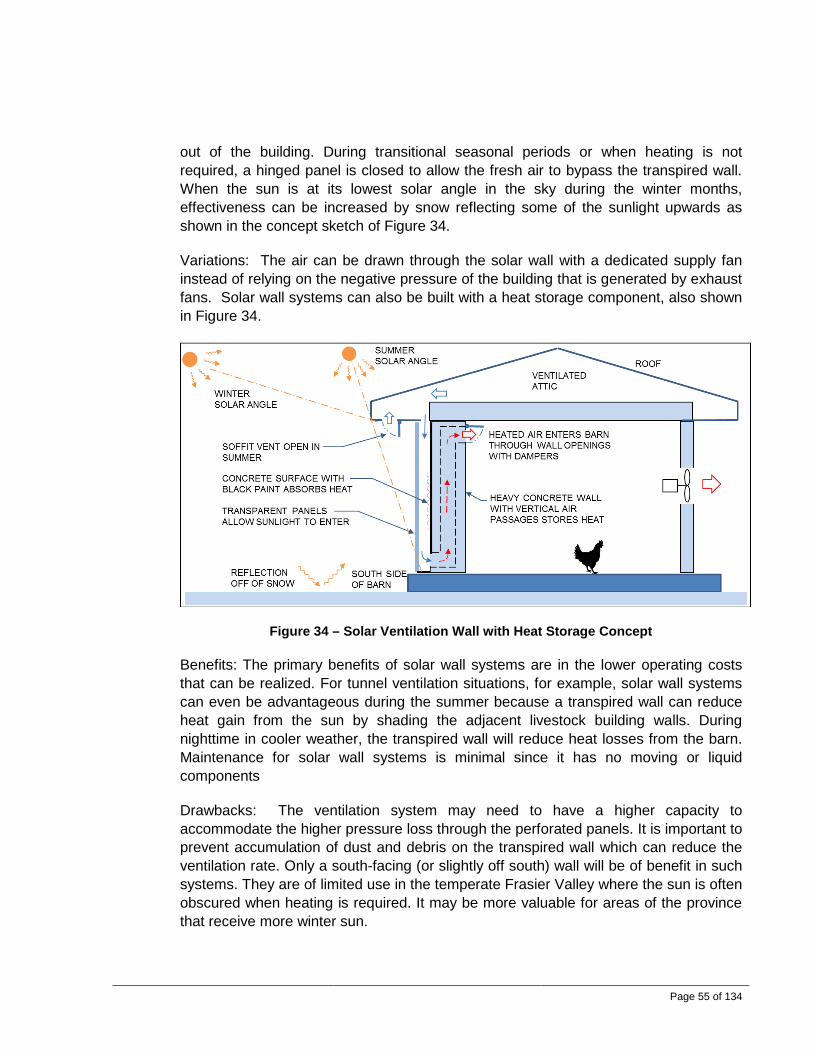
Page 55 of 134
out of the building. During transitional seasonal periods or when heating is not required, a hinged panel is closed to allow the fresh air to bypass the transpired wall. When the sun is at its lowest solar angle in the sky during the winter months, effectiveness can be increased by snow reflecting some of the sunlight upwards as shown in the concept sketch of Figure 34.
Variations: The air can be drawn through the solar wall with a dedicated supply fan instead of relying on the negative pressure of the building that is generated by exhaust fans. Solar wall systems can also be built with a heat storage component, also shown in Figure 34.
Figure 34 – Solar Ventilation Wall with Heat Storage Concept
Benefits: The primary benefits of solar wall systems are in the lower operating costs that can be realized. For tunnel ventilation situations, for example, solar wall systems can even be advantageous during the summer because a transpired wall can reduce heat gain from the sun by shading the adjacent livestock building walls. During nighttime in cooler weather, the transpired wall will reduce heat losses from the barn. Maintenance for solar wall systems is minimal since it has no moving or liquid components
Drawbacks: The ventilation system may need to have a higher capacity to accommodate the higher pressure loss through the perforated panels. It is important to prevent accumulation of dust and debris on the transpired wall which can reduce the ventilation rate. Only a south-facing (or slightly off south) wall will be of benefit in such systems. They are of limited use in the temperate Frasier Valley where the sun is often obscured when heating is required. It may be more valuable for areas of the province that receive more winter sun.

Page 56 of 134
Discussions: Transpired solar walls are already a proven concept with many already installed and operating throughout Canada.
Table 37 lists some common design parameters.
Table 37 –Solar Wall Common Design Parameters
Parameter Normal Range Air temperature rise Performance will vary.
For example, with an air flow of 18 m3/hr per m2 (1 cfm/ft2) and a solar influx of 200 W/m2, the temperature rise can be 10°C (18°F).
Solar Efficiency Up to 80% Air flow through transpired panel
Up to 128 m3/hr per m2 of wall (7 cfm per ft2)
Solar energy influx Up to 300 W/m2 (depending on weather, location, time of day, and day of year)
Thermal mass For every square foot of south-facing glass, use up to 150 pounds of masonry.
3.5.6 Passive Solar Air Heater
Figure 35 - Passive Solar Air Heater Concept
Where it is used: This concept is employed worldwide in various types of buildings.
How it works: The passive solar air heater is also referred to as a thermosiphon or a Trombe Wall. In the northern hemisphere, the most direct sunlight is incident on the south side during winter. The solar collector is located along the length of the barn and should face true south. It can face up to 30° either way from south but there will be a

Page 57 of 134
slight loss of solar heating capacity and there will be a shift in the time of day for when maximum solar heating occurs. The design shown in Figure 35 is a covered-plate collector with little or no thermal storage. The entire assembly forms the outside wall of the building. The solar collector is an air-space formed by transparent airtight panels on the outside. Sunlight passes through the clear panels. A black screen material suspended in the airspace absorbs heat from the sun. The air within this space is heated by the screen. As it heats, it becomes more buoyant and flows upwards and out through the upper wall openings. These openings are fitted with a back-draft damper or an adjustable actuated damper. When the sun is at its lowest solar angle in the sky during the winter months, the solar system’s effectiveness is increased when snow reflects some of the sunlight upwards as shown in the sketch.
Variations: The interior wall can be constructed of concrete and coated with black paint that has a high solar absorptivity. Thermal storage can be incorporated with concrete to help even out the normal temperature swings that occur during a 24 hour period. Double or triple glazing will be required in colder climates. Some solar wall designs only have a concrete wall to serve as a thermal capacitance and do not have air vents. In such cases, electric blowers may be added to improve air circulation through the wall. A trellis may be added to provide shade and reduce heat gain during the summer. In addition, piping and tanks may be added to serve as a solar water heater.
Benefits: Solar wall systems will reduce costs for heating. These systems are relatively low cost and can be built with readily available materials. Electrical power is not needed for operation.
Drawbacks: The main drawback of solar walls is heat loss to the outside environment. Double or triple glazing may be required in colder climates. Some experts say that this type of system is not suitable for cold climates. This type of system may be difficult to control. Also, the internal air passages may be susceptible to fouling because the room air is recirculated through the wall. This may be particularly difficult to manage in a commercial livestock or poultry facility. This type of solar heat system will generally be more suited to farm machinery storage buildings and workshops.
Table 38 lists some common design parameters.
Table 38 –Passive Solar Air Heater Common Design Parameters
Parameter Normal Range Air temperature rise Up to 40°C (72°F) Air flow rate Very low Solar efficiency Up to 80% Solar energy influx Up to 300 W/m2 (depending on weather, location, time of day,
and day of year)

Page 58 of 134
3.5.7 Livestock Greenhouse Barns
Where it is used: The most common use for a greenhouse is to grow plants. The heat energy from the sun is trapped in the greenhouse after it enters through the transparent windows. Since the 1980s in the United States in particular, greenhouse barns have been used for housing calves and cows as well.
How it works: The greenhouse barn is essentially a large passive solar air heater. Greenhouse barns use a lightweight frame to support one or two layers of a transparent plastic film as a covering. When used as dairy barns, they must be adequately ventilated. Ridge vents, eave vents, and side vents may be used. In the summer, a greenhouse barn must be covered to reduce solar heat gains.
Variations: Various types of framing structure and windows may be used.
Benefits: One of the greatest advantages of livestock greenhouse barns is the high levels of natural light levels which contribute to improved health of the housed animals and lower lighting costs. Greenhouse barns may be less costly to build compared to other forms of dairy housing. Heating costs may be lower.
Drawbacks: When maintenance costs are included in a comparison between greenhouse and post frame barns, the greenhouse barn may be more expensive. If ventilation is inadequate, animals may be subjected to wide variations in air temperature and humidity. High ventilation rates in the summertime are essential to counter solar gains. Natural ventilation with a greenhouse barn requires careful management. The plastic covering of a greenhouse barn will need to be replaced periodically. The durability of the construction materials is a concern.
3.5.8 Heat Pumps for Heating and Cooling
Where it is used: This concept is employed worldwide in various types of applications.

Page 59 of 134
Figure 36 - Heat Pump Systems
How it works: Heat naturally flows from a high temperature source to areas or spaces with a lower temperature. A heat pump can do the opposite. It uses the refrigeration cycle to move heat from a low temperature source to a high temperature destination. Electrical energy is used to power the compressor. The heat pump is reversible. It can provide heating in the winter by removing heat from the ground and releasing it into the building. In the summer, it can be reversed to extract heat from the building and release it to the ground.
The Coefficient of Performance (COP) is defined by:
𝐶𝐶𝐶𝐶𝐶𝐶 =𝑈𝑈𝑈𝑈𝑒𝑒𝑒𝑒𝑒𝑒𝑒𝑒 𝐸𝐸𝐸𝐸𝑒𝑒𝐸𝐸𝐸𝐸𝐸𝐸 𝑒𝑒𝑒𝑒𝑓𝑓𝑓𝑓𝐼𝐼𝐸𝐸𝐼𝐼𝑒𝑒𝐼𝐼 𝐸𝐸𝐸𝐸𝑒𝑒𝐸𝐸𝐸𝐸𝐸𝐸 𝑒𝑒𝑒𝑒𝑓𝑓𝑓𝑓
Input energy is used to operate the refrigerant compressor and water recirculation pumps. Useful energy flow is the cooling that is achieved in the summer or the heating achieved in the winter.
A closed-loop ground-source heat pump system relies on the flow of glycol in a closed loop that is buried in the ground. The system creates ice in the ground during the winter when heating is delivered to the building. Essentially, the frost line goes very deep. During the summer, the ice in the ground is melted as the building is cooled and heat is dumped into the ground. Ground source heat pumps installed in this manner are much more efficient than air source heat pumps.
Heat pumps are usually rated in terms of ‘tons’. One ton is the rate of energy transfer required to melt one ton (2,000 lbs) of ice in 24 hours. The following equation shows the relationship between tons and other common energy units.
1 𝐼𝐼𝑓𝑓𝐸𝐸 =12,000 𝐵𝐵𝐵𝐵𝑈𝑈
ℎ𝐸𝐸= 3.517 𝑘𝑘𝑘𝑘
Variations: The heat pump can be coupled with virtually anything. Common applications are shown in Figure 36.
Benefits: A heat pump will deliver up to three times more energy than is required for its operation. Depending on costs and availability of other energy sources for heating, the heat pump may prove to have the lowest operating cost. Because the system is reversible, heating and cooling can be achieved with one system.
Drawbacks: Installation costs are usually quite high, especially for ground source heat pumps. The size of the electrical service usually needs to be increased, which in turn also typically requires a larger standby generator set. Maintenance costs are also higher due to the costs of compressors which are very expensive to replace when they

Page 60 of 134
fail. Also, heating coils are prone to dirt buildup. If coils are used for air conditioning, it will be essential to treat the coils to prevent rapid deterioration caused by corrosive components within the condensate combining with barn air. Standard commercial systems are not designed to withstand corrosive environments; proper material selection is therefore important.
Table 39 lists some common design parameters.
Table 39 – Heat Pump Systems Common Design Parameters
Parameter Normal Range Coefficient of Performance (COP) 2.0 to 5.0 Ground source heat pump horizontal loops (closed loop)
¾” to 3”Ø HDPE piping buried in the ground at up to 1.8m deep; soil should be wet and dense.
Ground source heat pump vertical loops (closed loop)
Comprise a large array of vertical bore holes with ¾” Ø HDPE U-tube piping. Up to 80 m (262 ft ) deep.
Heat pump system using open loops and clean ground water
3.8 to 11.4 litres/min (1 to 3 gpm) for each ‘ton’ of heat pump capacity.
3.6 Noise, Odour, Dust and Biosecurity 3.6.1 General
Agricultural facilities generate noise, odour, and dust. There are many options to consider for the control of these nuisances inside and outside of the facility. The tolerable level of external noise, odour, and dust is dependent on location. When designing the layout of a new facility, consideration must be given to the new facility’s generation of noise, odour, and dust as this will impact animal and human health inside the barn and neighbouring properties.
In livestock or poultry buildings, airborne dust consists of animal hair, skin, dry manure, feed, feather particles, pollen, insect parts, molds, fungi, viruses and/or bacteria.
Relatively high ventilation rates are common in warm weather. This results in reduced airborne dust levels within the facility. While total dust emissions in the summer may be higher, the dilution rate is also comparably higher. In cold weather, low ventilation rates result in higher dust levels within the facility. Winter ventilation rates are set to a minimum level to reduce drafting effects and heating costs; actual rates are based on a number of factors including animal densities, animal type, insulation levels, bedding, flooring, and the desired level of air quality by management. As the outside temperature increases, the barn warms up and ventilation rates increase proportionately.

Page 61 of 134
Barn dust particle sizes vary from less than 0.1 micron (µm) to over 100 µm. Inhalable coarse particles are defined by the Environmental Protection Agency (EPA) as larger than 2.5 µm and smaller than 10 µm, while fine particles are defined as 2.5 µm and smaller. The majority of the airborne dust inside livestock or poultry buildings is smaller than 5 µm and can be inhaled deeply into the lungs. This is a health risk. Large particles tend to settle out while the smaller more dangerous particles remain airborne. Small particles eventually exit the facility through the building exhaust system and are carried in a plume that leaves the property.
The concentration of dust in the air is affected by local air velocity, temperature, relative humidity, the type of ventilation system, feeding methods, stock density, facility cleanliness, and bedding materials.
Dust particles can absorb gases. Gaseous and odorous compounds may leave the building through the ventilation system. Removal of dust from the environment within livestock and poultry buildings may improve animal productivity while reducing the emission of airborne bacteria, ammonia and odour.
Working in livestock facilities may be a high risk occupation. Livestock workers are at risk for contracting a variety of respiratory diseases such as bronchitis, chronic Farmer Lung disease, occupational asthma, or organic dust toxic syndrome (ODTS). Depending on the proximity of neighbours and the levels of dust abatement methods employed, neighbours could also be exposed to these risks.
Nuisance noise can be reduced at three levels.
• Primary noise reduction occurs at the source and is achievable with sound attenuators on equipment such as fans.
• Secondary noise reduction methods are employed outside of the noise generation points. These include noise control earth berms and noise barrier fences.
• The third and least preferred method is to reduce the perceived sound levels where the noise reaches the receptor or neighbour. Reducing perceived sound levels at the receptor is challenging. Options include sound attenuating insulation or the generation of white noise.
Noises may be perceived as worse in the summer than in the winter because people are more likely to have their windows open in summer or stay outside for longer periods.

Page 62 of 134
3.6.2 Noise Control Earth Berms
Figure 37 - Noise Control Earth Berm Concept
Where it is used: Earth berms are used outside of any noise generating facility that has sufficient land area available and neighbours close by.
How it works: The earth berm absorbs and reflects sounds originating from the facility. Depending on the climate, vegetation such as grass or shrubs will further help to absorb the sound.
Variations: The berm may be covered with a wood chip or wood bark mulch. If the berm is densely covered with trees, it may not be as effective as it will tend to scatter high frequency noise.
Benefits: Sound levels are reduced for neighbours and the earth berm serves as a visual barrier. It is usually less expensive than a noise barrier fence.
Drawbacks: Maintenance requirements may include grass-cutting and pruning of shrubs. The earth berm requires more land area than a noise barrier fence.
Discussions: This is a successful method of reducing noise impacts. However, many farms will lack the area required to place a berm, and it may impact productive land making it economically unviable.
Table 40 lists some common design parameters.
Table 40 – Noise Control Earth Berms Common Design Parameters
Parameter Normal Range Sound attenuation Up to 20 decibels (dBA) Height of earth berm Up to 4 m (13 ft)
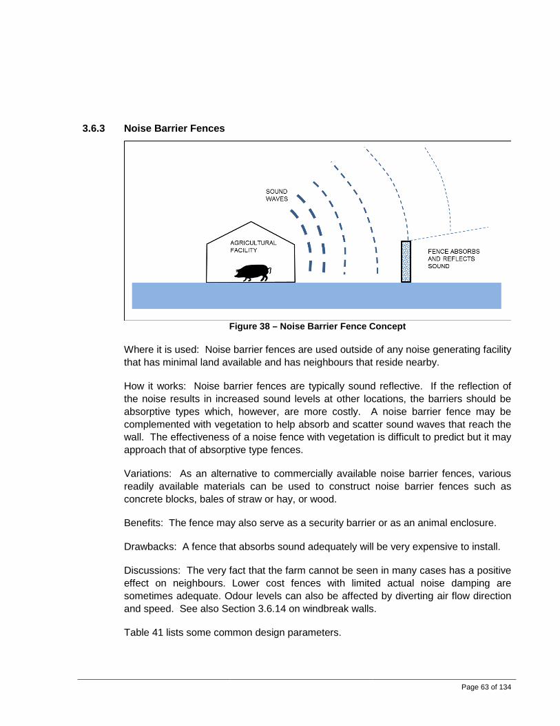
Page 63 of 134
3.6.3 Noise Barrier Fences
Figure 38 – Noise Barrier Fence Concept
Where it is used: Noise barrier fences are used outside of any noise generating facility that has minimal land available and has neighbours that reside nearby.
How it works: Noise barrier fences are typically sound reflective. If the reflection of the noise results in increased sound levels at other locations, the barriers should be absorptive types which, however, are more costly. A noise barrier fence may be complemented with vegetation to help absorb and scatter sound waves that reach the wall. The effectiveness of a noise fence with vegetation is difficult to predict but it may approach that of absorptive type fences.
Variations: As an alternative to commercially available noise barrier fences, various readily available materials can be used to construct noise barrier fences such as concrete blocks, bales of straw or hay, or wood.
Benefits: The fence may also serve as a security barrier or as an animal enclosure.
Drawbacks: A fence that absorbs sound adequately will be very expensive to install.
Discussions: The very fact that the farm cannot be seen in many cases has a positive effect on neighbours. Lower cost fences with limited actual noise damping are sometimes adequate. Odour levels can also be affected by diverting air flow direction and speed. See also Section 3.6.14 on windbreak walls.
Table 41 lists some common design parameters.

Page 64 of 134
Table 41 – Noise Barrier Fence Common Design Parameters
Parameter Normal Range Sound attenuation Up to 20 decibels (dBA) Height of fence Up to 4 m (13 ft)
3.6.4 Vegetative Buffers
Figure 39 - Vegetative Buffers Concept
Where it is used: Vegetative buffers are used to reduce sound levels, capture dust and odours, provide a visual screen, serve as a wind break, and provide shade.
How it works: Trees and shrubs provide a visual barrier around agricultural facilities. If non-farming neighbors cannot see something, they may be less likely to complain about nuisances. The vegetative buffer also captures odours and dust. When odours encounter a row of trees, the odour plume is disrupted and mixes with the prevailing wind, reducing odours. Ammonia gas is absorbed by plants.
Variations: It is best to use several different species of vegetation. This reduces the risk of loss or destruction of the entire windbreak if insect pests or tree diseases affect certain species. Diversity helps ensure survival during alternating seasons of drought and wet conditions.
Benefits: Windbreaks help filter and capture nutrients from runoff water through root absorption. Tree buffers provide visual and noise barriers which help improve relations with neighbours. Air velocity through the vegetative buffers is limited, which gives the dust time to settle.

Page 65 of 134
Drawbacks: A vegetative buffer needs to be very wide to achieve a reasonable level of noise abatement. Noise barrier fences or noise control earth berms are certainly more effective.
Discussions: A carefully designed buffer by a landscape architect or other professional is recommended. Buffer systems can be designed for rapid short term growth and longer term long lasting vegetation. Even with this assistance it can take years for benefits to accrue.
3.6.5 Misting Showers for Dust Abatement
Figure 40 - Misting Showers for Dust Abatement Concept
Where it is used: Intermittent oil sprays may be used to reduce dust levels in a livestock or poultry barn.
How it works: Intermittently sprinkling canola oil or mineral oil into the air helps reduce the respirable dust levels in barns. Dust particles stick to oil droplets and settle to the floor.
Variations: A low cost relatively easy option is to apply sprays by hand. Various types of oil may be used. Another approach is to use a “soaker system” in a swine finishing building which is normally used to apply water to the floor for cleaning. Oil can be injected into the soaker system as it operates intermittently. This may be effective but nozzles may be susceptible to clogging. Another option that has been investigated and demonstrated to be effective is the use of electrostatically-charged water sprays.
Benefits: Sprinklers operate within the building and introduce water directly into the air above the animals. They also help reduce re-entrainment of settled dust into the air. Workers and animals will benefit from cleaner air.

Page 66 of 134
Drawbacks: There may be safety concerns due to slippery floor surfaces. Other disadvantages relate to the additional labour required to manually apply oil sprays uniformly throughout a large facility and the greater difficulty in washing rooms with oil residues. Oil droplet size is very important because droplets that are too small could be inhaled by animals or workers whereas droplets that are too large will settle out too quickly. Although the concept has been proven, the many drawbacks and limited applications have not resulted in a commercial design and general farmer acceptance.
Table 42 lists some common design parameters.
Table 42 – Sprinklers for Dust Abatement Common Design Parameters
Parameter Normal Range Liquid to be sprayed Crude canola, purified canola, flax, corn,
sunflower or soybean oils Spray nozzle pressure 207 to 414 kPa (30 to 60 psi) depending on oil
type Rate of oil sprinkling per unit area of floor space
5 to 40 mL/m2 once every one to 14 days for swine buildings
3.6.6 Building Electrostatic Charge for Dust Abatement
Figure 41 - Building Electrostatic Charge for Dust Abatement Concept
Where it is used: Systems for which electrostatic charges are applied to building surfaces may be used in any agricultural facility to reduce airborne dust levels. It has been used in swine and poultry facilities and there are claims that it is very effective.
How it works: Electrostatic dust abatement systems work by imparting a negative charge on dust particles, causing them to stick to grounded interior surfaces of the building. These systems use suspended electrodes which are attached to a safe low

Page 67 of 134
current DC power supply. The system is sometimes referred to as the Electrostatic Space Discharge System (ESDS) or the Electrostatic Particle Ionization (EPI) System.
Variations: Electrostatic systems can also be installed in a ducted exhaust air stream to clean the air to reduce the downwind dust or odour nuisance to neighbors.
Benefits: It is a simple system that works within the interior of a livestock building to clean the air. Workers may benefit from superior air quality and animals may exhibit improved productivity. The building exhaust air will in turn be cleaner, reducing downwind nuisances to neighbors.
Drawbacks: Dust accumulates on interior surfaces and this must eventually be removed. The surfaces are typically cleaned with water, in which case the dust goes to the manure pit. Another alternative is to use an air compressor or a leaf blower to dislodge the dust so that the exhaust fans are able to draw the dust-laden air out. There is a potential for static shock if the electrodes are touched. In all cases, the potential for the accumulation of flammable dusts must be considered. Effectiveness of this type of system may be influenced by humidity levels in the facility. These systems may cause interference with existing electronics and controls. They may not be suitable for facilities that have high internal air velocities such as tunnel ventilated barns.
Discussions: This system has been evaluated in the Fraser Valley. There were issues with it at the demonstration level.
Table 43 lists some common design parameters.
Table 43 – Electrostatic System Common Design Parameters
Parameter Normal Range Electrode voltage Up to 30,000 V DC Efficiency Up to 80% reduction in airborne particulate

Page 68 of 134
3.6.7 Ducted Sound Attenuators
Figure 42 - Ducted Sound Attenuators Concept
How it works: Absorptive sound attenuators comprise sections of air conveying ducts that are lined with perforated plates which expose a sound attenuating media such as mineral wool insulation. Sound waves or vibrations pass through the attenuator and are absorbed by the media. These units can be located downstream of a centrifugal fan, for example, to reduce the noise released from the fan or other sounds generated within the livestock building and carried with the airstream.
Variations: Axial silencers comprise a cylindrical shell with a single round surface that absorbs the sound. They are sometimes equipped with a bullet-shaped axially located component that is lined with perforated plate and sound absorbing media. Rectangular absorptive silencers are equipped with multiple parallel panels that are lined with perforated plate, each filled with media.
Benefits: Sound attenuators of any type result in reduced sound levels that are potentially bothersome to neighbours. They may also be more cost effective in reducing sound levels at the source instead of building sound attenuating fences or incorporating dedicated equipment for such purposes.
Drawbacks: Absorptive sound attenuators are susceptible to the accumulation of particulate from a dust-laden airstream. This may reduce effectiveness and result in maintenance requirements. Although the concept has been proven in other industries, the issue of contamination and dust accumulation needs to be researched and tested more vigorously for an agricultural application before promotion or adoption is likely.
Where it is used: These units are commonly used in commercial and industrial applications, and at the present time are not commonplace in agricultural applications.

Page 69 of 134
3.6.8 Biosecurity: Air Filtration for Exhaust Air Cleaning
Where it is used: Exhaust fan air filters are starting to be installed on mechanically ventilated livestock buildings, especially in swine applications, to reduce pathogen release into the local environment. This is intended primarily to reduce the pathogenic risk to nearby farm operations. Washable low-efficiency pre-filters are commonly installed upstream of the main pathogenic filters help increase life span.
How it works: There are two common systems in use. A first system is to draw air through a filter bank with an exhaust fan that draws air from a plenum. In most cases, the filters will rapidly accumulate particulates. See Figure 43. The most effective maintenance method is to incorporate reusable washable filters and clean the filters while they are in position. A heavy duty vacuum cleaner can be used to clean the filters. The filters can be arranged in a V-bank pattern to make them more compact. A second system comprises an arrangement where a filter is placed on the intake or exhaust side of the fan itself, significantly reducing the space requirements of the first system noted above. Again, maintenance is a major issue.
Variations: In applications where dust loads are low, the filters can be disposable bag-type filters.
Figure 43 - Air Filtration for Exhaust Air Cleaning Concept
Benefits: The primary benefit of air filtration systems are that airborne pollutants are reduced, resulting in better conditions within and outside the facility. Drawbacks: Moisture accumulation in the filters can rapidly lead to reduced air flow. The filters need to be routinely monitored and cleaned. The fans need sufficient additional capacity to accommodate the increased system head loss. Filter maintenance is usually considered excessive. Table 44 lists some common design parameters.

Page 70 of 134
Table 44 – Exhaust Air Filters Common Design Parameters
Parameter Normal Range Filter type Washable or bag type Face velocity Up to 2.5 m/s (500 fpm) Head loss Up to 0.25 kPa (1 inch w.c.)
3.6.9 Biosecurity: Intake Air Biofiltration
Where it is used: To reduce the risk of airborne pathogen entry, air filters are occasionally used on mechanically ventilated livestock buildings to clean the fresh air before it enters the barn. They are typically used only during the winter, spring or fall seasons when barn air flows are lower. Use of filtration systems through the warmer summer season may be necessary if local pathogen risks are deemed to be high.
How it works: Air is drawn through filter boxes located in the attic plenum above the ceiling-mounted air inlet air intakes. The barn’s exhaust fans create a negative pressure in the barn, causing air to be drawn in. A ‘V-bank’ filter mounting arrangement can be used to achieve the required amount of filter area. Washable low efficiency pre-filters are commonly installed upstream of the main pathogen arresting filters to help increase their life span.
Figure 44 - Intake Air Filtration Concept
Benefits: Filtering of intake air helps prevent the spread of airborne viruses such as porcine reproductive and respiratory syndrome (PRRS) and other bacteria and viruses. Winds may carry the PRRS virus more than 10 km.
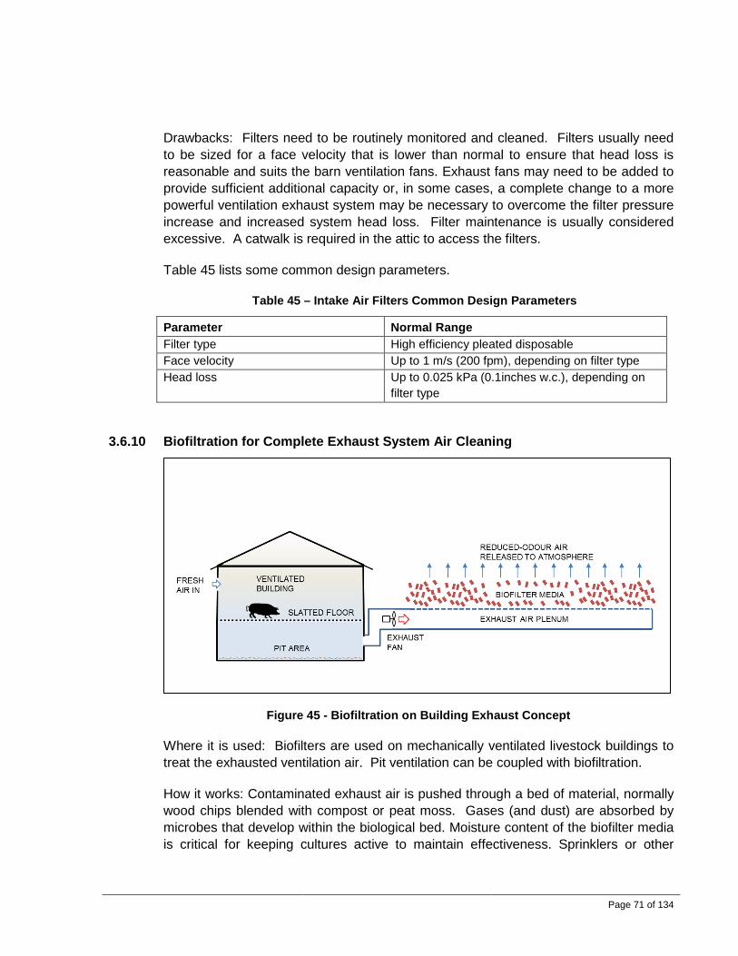
Page 71 of 134
Drawbacks: Filters need to be routinely monitored and cleaned. Filters usually need to be sized for a face velocity that is lower than normal to ensure that head loss is reasonable and suits the barn ventilation fans. Exhaust fans may need to be added to provide sufficient additional capacity or, in some cases, a complete change to a more powerful ventilation exhaust system may be necessary to overcome the filter pressure increase and increased system head loss. Filter maintenance is usually considered excessive. A catwalk is required in the attic to access the filters.
Table 45 lists some common design parameters.
Table 45 – Intake Air Filters Common Design Parameters
Parameter Normal Range Filter type High efficiency pleated disposable Face velocity Up to 1 m/s (200 fpm), depending on filter type Head loss Up to 0.025 kPa (0.1inches w.c.), depending on
filter type
3.6.10 Biofiltration for Complete Exhaust System Air Cleaning
Figure 45 - Biofiltration on Building Exhaust Concept
Where it is used: Biofilters are used on mechanically ventilated livestock buildings to treat the exhausted ventilation air. Pit ventilation can be coupled with biofiltration.
How it works: Contaminated exhaust air is pushed through a bed of material, normally wood chips blended with compost or peat moss. Gases (and dust) are absorbed by microbes that develop within the biological bed. Moisture content of the biofilter media is critical for keeping cultures active to maintain effectiveness. Sprinklers or other

Page 72 of 134
wetting systems are required, especially during warm months, to ensure the biological system can survive.
Variations: There are two main design configurations for biofilters. Flat beds are easier to construct and cost less; however, they occupy more space. Vertical biofilters, on the other hand, incorporate media in a wall rather than in a horizontal arrangement and therefore require a smaller footprint. Vertical biofilters are more difficult to construct and media material can settle, leading to gaps within the media matrix.
Benefits: Biofilters are effective on many types of contaminants. They are constructed of readily available materials and are usually easy to build. They will also reduce noise from the fan system.
Drawbacks: Particulate from the airstream is filtered out by the biological media. This will lead to increased pressure loss and reduced air flow, particularly in dusty applications as dust accumulates within the biofilter. This is an issue in all animal housing. To avoid plugging, some type of pre-filtration can be used upstream of the biofilter. Other drawbacks include the following:
• This system requires significant maintenance and rodent control. • Moisture levels are critical for proper operation. • The system needs a large area to incorporate the filtration components. It might
not be practical therefore to filter all the ventilation air of a building. • Higher pressure drop is common in such systems for the same air flow rate in
more conventional setups. For retrofits, fans that can provide the desired CFM at the higher pressures are required, or air exchange rates will drop.
• Higher energy costs for the same air exchange rates are typical.
Discussions: These systems have been in use for many years, although it is not uncommon to see them abandoned after time. They can be fairly costly to build, take time to maintain and may not be compatible with existing ventilation fans. Pit ventilation exhaust fan systems are the most promising application for biofiltration.
Table 46 lists some common design parameters.
Table 46 – Biofiltration Common Design Parameters
Parameter Normal Range Common types of media Peat, soil (heavy loam), compost (yard waste), wood
chips, straw Air flow rates 91 to 1828 m3/hr per m2 (5 to 100 cfm /ft2) of media area Pressure drop Up to 0.5 kPa (2 inches w.c.) Depth 0.25 to 0.61 m (10 to 24 inches) Gas residence time in biofilter 3 to 10 seconds

Page 73 of 134
3.6.11 Wet Scrubbers for Exhaust Air Cleaning
Where it is used: Wet scrubbers are used on mechanically ventilated livestock buildings to treat the exhausted ventilation air.
How it works: Many types of wet scrubbers are available. The principles of operation are the same for all types. Contaminants such as particulate and gases in an airstream are trapped in a scrubbing liquid, after which the liquid is separated from the airstream. In agricultural buildings, the most common application employs a permeable media that is constantly wetted with spray showers. The scrubbing liquid can be recirculated or drained to a sump for transference to a sewer or disposal in some other manner.
Figure 46 - Wet Scrubber Concept
Variations: Some scrubbers use water which is partially recirculated and some use an acid or a base to shift the pH in order to absorb specific gases in the air. For those which absorb gases, the resulting liquid effluent is a waste product. Multiple stages can be incorporated to combine different scrubbers to treat multiple pollutants. Scrubbers are either acid scrubbers, bioscrubbers, or water-only scrubbers. Acid scrubbers trap alkaline material, such as ammonia, in a sulfuric acid solution. Bioscrubbers rely on bacteria growing on biomass within the scrubber to convert ammonia into nitrate and nitrite. Water-only scrubbers are similar to the acid scrubbers and bioscrubbers except that they only use water.
Benefits: Bioscrubbing equipment is effective on various gases, odours and particulate matter. Scrubber stages can easily be designed to suit specific applications. A dosing pump can be used to add acid to the water to help remove ammonia from the exhaust.

Page 74 of 134
Drawbacks: Scrubbers are expensive to implement and maintain. Effluent streams that are generated require disposal. Increased water use may also be an issue. Using scrubbers in a cold climate may be a challenge. Poor maintenance may result in plugging and reduced system air flow. The higher capital and operating costs make it a low priority consideration for commercial farms.
Table 47 – Wet Scrubber Use
Industry Applications Suitability of Use Dairy all not used Poultry broiler chicken and layers,
turkey grower, sometimes
Swine swine finisher and breed/gestation sometimes
Table 48 lists some common design parameters.
Table 48 – Wet Scrubber Common Design Parameters
Parameter Normal Range Air flow rates Up to 4300 m3/hr per m2 (235 cfm /ft2) of media area Pressure drop Up to 0.5 kPa (2 inches w.c.) Removal efficiencies Up to 85% of ammonia, up to 90% of airborne dust
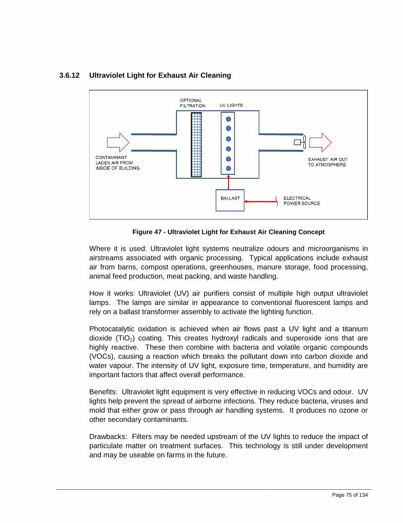
Page 75 of 134
3.6.12 Ultraviolet Light for Exhaust Air Cleaning
Figure 47 - Ultraviolet Light for Exhaust Air Cleaning Concept
Where it is used: Ultraviolet light systems neutralize odours and microorganisms in airstreams associated with organic processing. Typical applications include exhaust air from barns, compost operations, greenhouses, manure storage, food processing, animal feed production, meat packing, and waste handling.
How it works: Ultraviolet (UV) air purifiers consist of multiple high output ultraviolet lamps. The lamps are similar in appearance to conventional fluorescent lamps and rely on a ballast transformer assembly to activate the lighting function.
Photocatalytic oxidation is achieved when air flows past a UV light and a titanium dioxide (TiO2) coating. This creates hydroxyl radicals and superoxide ions that are highly reactive. These then combine with bacteria and volatile organic compounds (VOCs), causing a reaction which breaks the pollutant down into carbon dioxide and water vapour. The intensity of UV light, exposure time, temperature, and humidity are important factors that affect overall performance.
Benefits: Ultraviolet light equipment is very effective in reducing VOCs and odour. UV lights help prevent the spread of airborne infections. They reduce bacteria, viruses and mold that either grow or pass through air handling systems. It produces no ozone or other secondary contaminants.
Drawbacks: Filters may be needed upstream of the UV lights to reduce the impact of particulate matter on treatment surfaces. This technology is still under development and may be useable on farms in the future.

Page 76 of 134
3.6.13 Non-Thermal Plasma for Exhaust Air Odour Abatement
Where it is used: Non-thermal plasma systems neutralize odours in airstreams associated with organic processing. Typical applications include exhaust air from barns, compost operations, greenhouses, manure storage, food processing, animal feed production, meat packing, and waste handling.
How it works: Fresh air is forced through cold plasma (also known asnon-thermal plasma or NTP) fields to create activated air that is injected into the reactor or mixing chamber. Electricity is used to create the cold plasma field. This field activates the oxygen and water vapour in the air, converting a portion to hydroxyl radicals. The hydroxyl radicals have a wide range of ionization levels and are very reactive. The field is fully adjustable, much like a light dimmer, so it can be adjusted to suit the odour load.
Figure 48 - Non-Thermal Plasma for Exhaust Air Odour Abatement Concept
The reactor/mixing chamber is simply a large enclosure where the activated air is allowed to mix with the contaminated air. The contaminated air is drawn through the chamber where the activated air is injected. The injection air contains radicals and ionized oxygen species that readily react with the organic compounds in the contaminated air to convert them to simpler compounds. The chemical reactions transform the odorous molecules in the air to non-odorous forms that can no longer be sensed by people.
Variations: The most common way to implement a cold plasma odour control system is to inject the air that is activated by the cold plasma field into an odorous air stream. In some applications, the cold plasma fields may be located directly in the exhaust air stream but this may lead to fouling.

Page 77 of 134
Benefits: Cold plasma systems only use electricity for their operation. The only consumable parts of the process are standard type air filters for the injection air. The components of the electrodes that create the field should never wear out.
Drawbacks: Cold plasma systems emit low levels of ozone as part of their operation, as ozone forms part of the reactive species created. If a cold plasma system is misadjusted, the level of ozone could exceed ozone emission guidelines. The ozone emissions can, however, be used as a benefit in some cases. If set correctly, for example, some of the emitted air can be recirculated back into the odour source, such as a barn, to help with suppression of internal odours. Some literature also shows additional benefits associated with low level ozone in a barn setting, such as suppression of insects, an increased antibacterial environment, and better feed conversion efficiencies. The energy consumption in cold plasma applications is very high, typically 0.25 to 1.0 kW per 1,000 cfm. Assuming an electrical rate of $0.08 per kWh, it would cost up to $11,900 a month to treat air from a chicken barn ventilated at a rate of 200,000 CFM. This technology is still under development and may be useable on farms in the future.
Table 49 lists some common design parameters.
Table 49 – Non-Thermal Plasma Common Design Parameters
Parameter Normal Range Pressure drop Very low Energy consumption 0.53 to 2.12 kW per m3/s (0.25 to 1.0 kW per 1,000 cfm)
3.6.14 Windbreak Walls
Figure 49 - Windbreak Wall Concept

Page 78 of 134
Where it is used: Windbreak walls are commonly used in the exhaust areas of a barn that are experiencing negative impacts from wind and snow. Examples include tunnel ventilation air flow rates reduced by wind effects and reduced ventilation rates caused by snow drifts accumulating in front of fans in winter. Walls are also effective at reducing the impacts caused by exhaust air patterns towards sensitive areas including other nearby farms and other neighbours.
How it works: Windbreak walls are barriers that can be located downwind of exhaust fans to reduce the momentum of airflow, to settle out dust particles, and to divert the exhaust air plume higher into the atmosphere to achieve better mixing with ambient air by creating a more dilute contaminant concentration.
Windbreak walls are designed to be capable of resisting the ambient wind loading as well as the impulse loading of the fan exhaust air stream. The distance between the fan and the wall is a critical dimension. If the barrier is too close to the fan outlet, it may reduce the ventilation capacity.
Variations: The typical wind break barrier may be constructed of treated wooden posts with a frame and an ultraviolet-resistant tarp material. Exterior grade plywood may also be used in place of a tarp. The wall panels may incorporate sound absorbing media to help reduce sound levels. An interesting alternative is to use a wall comprising corn stalks or straw between layers of chicken wire to create a biomass mat that can serve to attenuate sound and capture particulate and odours.
Benefits: Windbreak walls are relatively easy to incorporate. Dust emissions may be reduced as some particulate will tend to settle out within the enclosure. Odours and dust are released at a higher elevation with benefits similar to those of an exhaust stack. Sound levels may also be reduced.
Drawbacks: Buildings that do not use tunnel ventilation may be more costly to outfit with wind break barriers because fans are located at several places around the building. This type of equipment may require additional reinforcement in particularly windy areas. It may also create additional odours around the farm.
Discussions: This is an effective system if areas around farm buildings are available to erect a fence.
Table 50 lists some common design parameters.
Table 50 – Wind Break Walls Common Design Parameters
Parameter Normal Range Pressure drop Very low Fence height Up to 4 m (12 feet) Fence width Width of end of barn

Page 79 of 134
Fence materials Wood, steel, and/or tarps
3.6.15 Exhaust Stacks
Figure 50 - Exhaust Stack Concept
Where it is used: Exhaust stacks may be used on any building or process that incorporates a system to exhaust contaminated air:, however, stacks are rarely seen in agricultural applications, primarily due to the very high costs.
How it works: The contaminated exhaust air is discharged at a high elevation where it is diluted with ambient air making up the prevailing wind airstream. It is good practice to equip the stack with a drain to handle condensate or rain water that may enter the stack.
Variations: Variations in height and discharge velocity greatly affect the performance.
Benefits: The contaminated air is diluted before it is exposed to neighbours.
Drawbacks: Exhaust stacks are costly to construct and operate. Additional fan pressure is required. Maintenance of the stack is very difficult, especially in colder weather time periods when condensation and heat loss of the exhaust air occurs. A central exhaust collection duct or plenum is required. Stacks have a negative impact on the aesthetic landscape, and also may also be negatively perceived by the public and neighbours. Furthermore, depending on the overall stack height and farm location, the stack may be subject to Transport Canada regulations, requiring additional permitting, marking and lighting.
Table 51 lists some common design parameters.
Page 80 of 134
Table 51 – Exhaust Stacks Common Design Parameters
Parameter Normal Range Pressure drop Greatly depends on outlet velocity Stack height Usually higher than barn roof Stack materials Steel with concrete base
3.6.16 Site Selection and Yard Layout
When a farm is being purchased or a new livestock/poultry barn is being considered, the impacts of any odours, noise and dust are best considered at the design and site planning stage.
By following basic rules and considering all consequences, future issues can be minimized. Some considerations include the use of the minimum distance separation (MDS) formula for setbacks from roads and neighbours and the use of existing natural barriers such as wooded areas, tree shelters, berms, hills and the like. Refer also to Section 8.4.3.
Observing what a given local community has encountered in terms of complaints ̶ and the methods employed to resolve them ̶ will help avoid future problems.
It is important to start up a new facility with the knowledge that due process, care and consideration has been attended to. Costly disputes with neighbours can be avoided.
There may be additional upfront costs that may not have been initially considered when developing the economics for the new facility.

Page 81 of 134
4.0 THEORETICAL CONSIDERATIONS FOR VENTILATION OF AGRICULTURAL BUILDINGS
4.1 General In this section, a high level description of the key theoretical considerations are included to give the interested reader a good understanding of the important aspects of the calculations involved in the proper sizing and selection of HVAC equipment for agricultural buildings.
4.2 Energy and Mass Balance The flow of energy and mass moving into and out of a facility must be accounted for. It is beyond the scope of this report to present more details. Figure 51 shows a generic concept sketch that shows many of the important aspects to be considered.
Figure 51 - Energy and Mass Balance
The overall objective is to design a system that maintains suitable temperature, humidity and air quality in the conditioned space. In most cases, the properties of the exhausted air can be considered to be the average properties of the room air.
4.3 Properties of Moist Air 4.3.1 General
To understand the ventilation requirements of agricultural facilities, it is important to understand psychrometrics. This specialized area of thermodynamics is the study of atmospheric air mixed with varying amounts of water vapour.
The basic psychrometric chart is shown in Figure 52 and is based on standard atmospheric pressure at sea level. This type of chart can be used to determine air

Page 82 of 134
properties and visualize the various processes involved in moist air conditioning processes. Other charts are available for higher elevations where the atmospheric pressure is lower.
Figure 52 - Psychrometric Chart
A psychrometric chart may look complicated but it is quite simple. A ‘state’ of moist air can be defined by any single point on the chart. As an example, the state shown as a dot on the chart in Figure 52 has the following properties:
• Dry bulb temperature of 20°C • Wet bulb temperature of 11.5°C • Dew point temperature of 4°C • Enthalpy of 33 kJ/kgda (kilojoules per kilogram of dry air) • Humidity ratio of 5 g/kgda (grams per kilogram of dry air) • Relative humidity of 35%.
All of the important properties are defined by a single point on the chart. Adding or removing sensible or latent heat, for example, from the sample of air will cause the point to shift to another location on the chart.
Because the amount of vapour in dry air varies during psychrometric processes and states of change of given air volumes, it is useful to express specific properties in terms of per unit mass of dry air (kgda).

Page 83 of 134
4.3.2 Dry Bulb Temperature
The dry bulb temperature is the temperature that is measured with a regular thermometer. It is always equal to or greater than the wet bulb temperature.
The dry bulb temperature within a barn should be lower than the body temperature of the housed animals so that sensible cooling of the animal’s body can be achieved.
4.3.3 Wet Bulb Temperature
A wet bulb thermometer is similar to a dry bulb thermometer but it has a wetted surface at one end. Water evaporates from the surface to give a localized cooling effect. If the air is very dry, the water will evaporate quickly and the wet bulb thermometer will indicate a temperature that is much lower than the dry bulb temperature. If the air is very humid, the wet bulb temperature will be close to, but not greater than, the dry bulb temperature. If the air is saturated and is holding as much moisture as it possibly can, then the wet bulb temperature will be equal to the dry bulb temperature.
4.3.4 Dew Point Temperature
At any given state, if sensible cooling is applied (defined as the process during which the humidity ratio is kept constant but heat is removed), the air’s dry bulb temperature will continue to decrease until the air eventually reaches 100% relative humidity. At the point where the relative humidity is 100%, the new dry bulb temperature will be the dew point temperature of the air in question.
When air is fully saturated, all three temperatures are equal, i.e., the dew point temperature is equal to both the wet bulb temperature and the dry bulb temperature.
4.3.5 Relative Humidity
As shown in Figure 52, the curved lines on the psychrometric chart show constant relative humidity.
Atmospheric air contains varying amounts of water vapour. In general, air holds more water vapour at higher temperatures. The relative humidity is expressed as a percentage and is approximately equal to the ratio of the mass of water vapour that is in the sample to the maximum mass of water vapour that it can hold at a given dry bulb temperature.
Relative humidity is not the best parameter to consider when quantifying the moisture level of the air because its relative humidity changes as the dry bulb temperature changes, even without a change in the moisture content of an air sample. This may lead to confusion on occasion.

Page 84 of 134
For a given temperature and pressure, there is a maximum amount of water vapour that air can hold. When air has a relative humidity of 100%, it is holding as much water vapour as possible at a given dry bulb temperature. If the dry bulb temperature of saturated air is increased, the relative humidity will be less than 100%. If the dry-bulb temperature of saturated air is decreased, condensation will occur.
Cold air cannot hold very much moisture and is often referred to as dry air even though its relative humidity can often be quite high. As air warms up, it not only expands in volume, but its ability to absorb or hold moisture increases dramatically. This property allows cold fresh air entering a barn ̶ which warms up to room temperature as it mixes ̶ to ‘sponge up’ water vapour from the animals and from wet floor surfaces.
In a hot dry climate, evaporation occurs more rapidly. If humidity levels are low, irritation of the mucous membranes may result.
In a hot humid climate, the ability of the air to absorb additional moisture is limited. If the room air temperature is too high, animals are unable to lose much sensible heat resulting in heat stress. When humidity levels are high, it may promote growth of fungus infections. High humidity may also contribute to deterioration of building structures. Ideally, the relative humidity in a barn should be in the range of 40% to 80%. In hot humid climates such as in the southeastern United States, the relative humidity within poultry housing can be as high as 80% to 90%.
4.3.6 Humidity Ratio
The humidity ratio is a very important parameter in psychrometrics. It is defined as the mass of water vapour per unit mass of dry air. It is best to work with this parameter instead of relative humidity when doing calculations involving heat and mass transfer.
The humidity ratio is shown on the right hand vertical axis on the psychrometric chart.
4.3.7 Specific Volume
The specific volume is also shown on the psychrometric chart. In general, higher humidity levels and/or higher temperatures equate to increased specific volumes. Because of these moisture and temperature variations associated with specific volume, stratified layers of air with varying specific volume will occur if there is insufficient mixing in a room. Water vapour, for example, has a lower density than dry air at the same temperature.
Cold air with a lower specific volume is denser than warm air and will therefore tend to sink to floor level once it is released into a warm building. For this reason, cold air is always introduced at or near the top of the sidewall or through the ceiling from the attic space and directed horizontally across the ceiling surface to allow it to warm up prior to reaching the animals.

Page 85 of 134
Higher humidity levels and/or higher dry bulb temperatures result in increased specific volume, i.e., reduced density of air within a barn.
4.3.8 Enthalpy
The enthalpy of a sample of air is equal to the energy associated with sensible heat plus latent heat. Latent heat is the energy content of air that is directly proportional to the amount of water vapour contained in the sample of air. Sensible heat is the energy content directly proportional to the dry bulb temperature of the air.
Specific enthalpy is expressed in terms of energy per unit mass of dry air because the moisture content an air sample will vary as water evaporates or condenses, whereas the amount of dry air remains constant. In the SI system of units, the enthalpy of dry air is zero at zero degrees Celsius. The enthalpy can be calculated or it can be read from a psychrometric chart.
Generally, the air has a higher enthalpy with increased dry bulb temperature and/or increased humidity ratio.
4.4 Moist Air Conditioning Processes 4.4.1 General
The psychrometric chart shown in Figure 53 can be used to illustrate psychrometric processes that occur in agricultural buildings.
Moist air undergoes a conditioning process whenever it changes from one state to another. Any conditioning process can be represented as a straight line from one point (State 1) to another point (State 2) on a psychrometric chart.
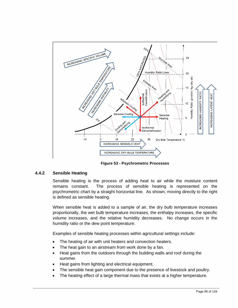
Page 86 of 134
Figure 53 - Psychrometric Processes
4.4.2 Sensible Heating
Sensible heating is the process of adding heat to air while the moisture content remains constant. The process of sensible heating is represented on the psychrometric chart by a straight horizontal line. As shown, moving directly to the right is defined as sensible heating.
When sensible heat is added to a sample of air, the dry bulb temperature increases proportionally, the wet bulb temperature increases, the enthalpy increases, the specific volume increases, and the relative humidity decreases. No change occurs in the humidity ratio or the dew point temperature.
Examples of sensible heating processes within agricultural settings include:
• The heating of air with unit heaters and convection heaters. • The heat gain to an airstream from work done by a fan. • Heat gains from the outdoors through the building walls and roof during the
summer. • Heat gains from lighting and electrical equipment. • The sensible heat gain component due to the presence of livestock and poultry. • The heating effect of a large thermal mass that exists at a higher temperature.

Page 87 of 134
• The heating of air by transpired solar walls.
Heat gains from the outdoors through the building walls and roof during the summer often account for a small portion of the heat gains in a barn. A full poultry house typically experiences 95% of its heat gains to the birds themselves.
4.4.3 Sensible Cooling
In contrast to sensible heating, sensible cooling is the process of removing heat from the air while the moisture content remains constant. The process of sensible cooling is represented on the psychrometric chart by a straight horizontal line which moves directly to the left.
When sensible heat is removed from the air, the dry bulb temperature decreases proportionally, the wet bulb temperature decreases, the enthalpy decreases, the specific volume decreases, and the relative humidity increases. No change occurs in the humidity ratio or the dew point temperature.
If enough sensible cooling occurs, the dry bulb temperature will reach the dew point temperature, the relative humidity will reach 100%, and condensation will occur. An example of this is when water droplets form on a cold window pane or on the interior surface of a building wall. In cold climates, barn walls must be adequately insulated so that condensation does not occur. Barns are particularly susceptible to this problem because they may occasionally operate with higher than desired humidity levels.
Condensation can also occur in the wall cavity of a pressurized barn. When a barn operates under a positive pressure ventilation system, the warm humid air can be forced through cracks and openings in the building envelope. During the winter, the humid air cools as it passes through the wall and when it cools to the dew point temperature, condensation occurs. This may result in the rapid accumulation of water (possibly several litres per hour) that saturates insulation and deteriorates the building structure.
Common examples of sensible cooling in agricultural applications include:
• Heat losses to the outdoors through the building wall during the winter. • The cooling achieved by an earth tube system or an indirect evaporative cooler. • The cooling effect of a large thermal mass that exists at a lower temperature than
the temperature within the barn.
4.4.4 Isothermal Humidification (Latent Heat Addition)
An isothermal process is a thermodynamic process which happens without a change in dry bulb temperature. Only latent heat is added to the air but the dry bulb temperature does not change.

Page 88 of 134
When live steam at atmospheric pressure is released into an airstream, significant energy is added to the airstream. The humidity ratio increases but the dry bulb temperature remains constant. Steam humidification systems use heat from an external source, such as electricity, natural gas, or boiler steam, to convert water to vapour. Essentially, the energy required to vaporize the water does not come from the air, as is the case with evaporative cooling.
Examples of isothermal humidification processes in an agricultural setting include:
• In cold climates, the addition of steam to supply air that is sent to a conditioned space.
• The latent heat gain component generated from the animals themselves.
4.4.5 Adiabatic Cooling (Evaporative Cooling)
An adiabatic process is a thermodynamic process which happens without a net loss or gain of enthalpy. Enthalpy is latent heat plus sensible heat. In an adiabatic process, latent heat is added to the air and an equal amount of sensible heat is removed. The sensible heat that is removed is the heat energy that is consumed in the process of vaporizing the water. It is essentially a trade-off of the two different types of energy.
Adiabatic humidification systems use sensible heat from the air to convert water into vapour. This is commonly referred to as evaporative cooling. When liquid water is introduced to the airstream, sensible heat in the air is converted to latent heat contained in the added vapour. This results in air that has a lower dry bulb temperature but has increased humidity. No significant changes occur to the wet bulb temperature or the enthalpy. The water is at the same temperature as the wet bulb temperature of the air.
Adiabatic cooling (evaporative cooling) can only occur if the air is not saturated with water vapour. If the air is already saturated, water will not evaporate into the air.
When evaporative cooling is used to reduce the dry bulb temperature inside of a barn, it has a negative impact because the relative humidity is increased and this reduces the ability of animals to lose latent heat energy. However, the reduced dry bulb temperature enables animals to increase their loss of sensible heat.
Evaporative cooling increases the relative humidity of the air in the barn space. The relative humidity in the barn should never exceed 80% during warm weather, as this may cause the animals distress.
Typical adiabatic (evaporative) cooling processes within a barn setting may include:
• In hot dry climates, high pressure water misting showers in a ventilation system airstream for cooling of conditioned spaces., Example: 7.5 litres/min of water
Page 89 of 134
evaporated into an airstream with a flow of 76,456 m3/hr (45,000 cfm) will change its state from 45°C and 23% RH to (31.4°C and 68% RH.
• The evaporation of water from evaporative cooling media pads into the airstream as the fresh ambient air is drawn into a barn.
• The evaporation of water in a conditioned space from equipment, appliances, and water tubs.
• The air drying of wet materials.
4.4.6 Heating and Humidification of Air by Animals
The process of heating and humidifying is a combination of adding sensible heat (sensible heating) and adding latent heat (isothermal humidification).
The presence of livestock and poultry will add sensible heat and moisture (latent heat) to the air in a barn. This is a very important process which occurs in all livestock and poultry housing. Livestock and poultry must continuously release energy to maintain their internal body temperature. The total energy they release is dependent on the type of animal and its activity level.
Latent heat gains to a barn originate from multiple sources such as:
• Water vapour that animals continuously release from their bodies in the form of perspiration
• Respiration moisture loss from the lungs of animals • Manure • Water systems (including spillage)
Perspiration and respiration give livestock/poultry the evaporative cooling effect needed to help cool their bodies. The latent heat gain from the animal increases the total enthalpy of the barn air, but it does not increase the dry bulb temperature in the barn.
Sensible heat gains realized by a barn from animals are attributable to the convective heat loss from their bodies. This sensible heat loss occurs as a result of a temperature differential between the ambient air in the barn and the temperature of their bodies. If the ambient room temperature is high, the sensible heat loss from their body will be low. The sensible heat loss can be increased by increasing convective heat transfer. The animal must be exposed to relatively high air velocities to achieve this. Examples include:
• High velocity circulation fans directed at the animal. • Tunnel ventilation systems with high air velocities flowing through the barn.

Page 90 of 134
The animal must lose a certain amount of heat to cool its body effectively to maintain the body temperature. Heat that cannot be lost from the body due to convection must be accomplished with latent heat loss through increased respiration and perspiration rates, for example. If the air is too humid, water cannot evaporate. The humidity levels within a barn should be high at the same time as the ambient barn temperature is high, or heat stress will occur.
Poultry will begin to ‘pant’ to shed heat at temperatures higher than 25°C. This method of controlling body temperature relies on evaporative cooling within the bird's own lungs to get rid of excess heat. When the bird is in a barn with very high relative humidity, it cannot release latent heat. Furthermore, the air in the room cannot absorb much moisture if the air is already nearly saturated. If the bird is unable to lose this excess heat, its core body temperature will rise, resulting in heat stress. This will lead to production losses and, in severe cases, increased mortality rates.
Animals continuously lose heat to maintain body temperature. Table 52 serves as a guide to predict the amount of latent and sensible heat that various animals produce for a given target ambient temperature. The heat generated by an animal is a function of many variables, including breed, age, weight, ambient temperature and activity level. Reliable data to suit every animal breed is not readily available.
The Sensible Heat Factor (SHF) is defined as:
𝑆𝑆𝑆𝑆𝑆𝑆 =𝑆𝑆𝑒𝑒𝐸𝐸𝑈𝑈𝑆𝑆𝑆𝑆𝑒𝑒𝑒𝑒 𝑆𝑆𝑒𝑒𝐻𝐻𝐼𝐼 𝐺𝐺𝑒𝑒𝐸𝐸𝑒𝑒𝐸𝐸𝐻𝐻𝐼𝐼𝑒𝑒𝐺𝐺𝐵𝐵𝑓𝑓𝐼𝐼𝐻𝐻𝑒𝑒 𝑆𝑆𝑒𝑒𝐻𝐻𝐼𝐼 𝐺𝐺𝑒𝑒𝐸𝐸𝑒𝑒𝐸𝐸𝐻𝐻𝐼𝐼𝑒𝑒𝐺𝐺
The SHF is greatly influenced by environmental conditions, including humidity levels, air temperature, and air speed. It normally varies between 30% and 90%, depending on environmental conditions and type of animal.
The SHF will be relatively low if the ambient humidity levels are low. The SHF will be high if the ambient humidity levels are high. When the air is very humid, the ability of a body to lose latent heat is inhibited because the moisture will not evaporate as readily. If the humidity levels are high and the air temperature is high, one must rely on increased air speeds to increase the animal’s ability to lose heat.
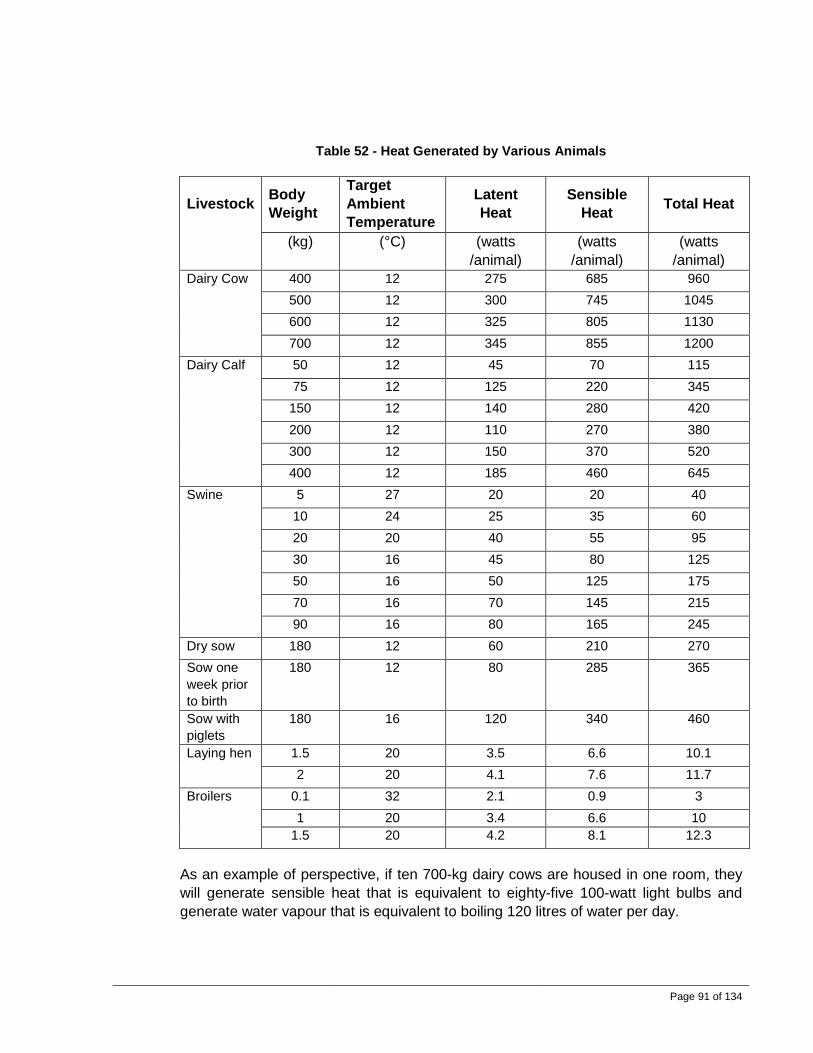
Page 91 of 134
Table 52 - Heat Generated by Various Animals
Livestock Body
Weight
Target Ambient Temperature
Latent Heat
Sensible Heat Total Heat
(kg) (°C) (watts /animal)
(watts /animal)
(watts /animal)
Dairy Cow 400 12 275 685 960 500 12 300 745 1045 600 12 325 805 1130 700 12 345 855 1200
Dairy Calf 50 12 45 70 115 75 12 125 220 345 150 12 140 280 420 200 12 110 270 380 300 12 150 370 520 400 12 185 460 645
Swine 5 27 20 20 40 10 24 25 35 60 20 20 40 55 95 30 16 45 80 125 50 16 50 125 175 70 16 70 145 215 90 16 80 165 245
Dry sow 180 12 60 210 270 Sow one week prior to birth
180 12 80 285 365
Sow with piglets
180 16 120 340 460
Laying hen 1.5 20 3.5 6.6 10.1 2 20 4.1 7.6 11.7
Broilers 0.1 32 2.1 0.9 3 1 20 3.4 6.6 10
1.5 20 4.2 8.1 12.3
As an example of perspective, if ten 700-kg dairy cows are housed in one room, they will generate sensible heat that is equivalent to eighty-five 100-watt light bulbs and generate water vapour that is equivalent to boiling 120 litres of water per day.

Page 92 of 134
For details regarding scientific data related to the heat and moisture generation rates of different species of animals, refer to Section 8.7.1 for various sources of such information.
4.4.7 Cooling and Dehumidifying
The process of cooling and dehumidifying is a combination of removing sensible heat and removing latent heat. This process occurs when air is exposed to a cold surface and condensation occurs.
An air conditioning unit which has a cooling coil with a temperature that is lower than the dew point of the air will cool and dehumidify the air. Condensation will occur on the cooling coil.
During cold weather, cooling and dehumidifying, for example, occur on the interior surface of a cold window pane or the interior surface of a building wall that is not adequately insulated.
4.5 Fresh Air Intakes 4.5.1 General
The type of climate in which an agricultural facility is located will have an influence on the design of the ventilation systems. There is a wide variety of weather conditions throughout the province and each application must be assessed individually.
In warm dry climates, evaporative cooling with high pressure mist is very effective for cooling fresh air at intake areas.
In cold climates, consideration must be given to preheating the fresh intake air or distributing the fresh air to ensure that animals are not exposed to cold drafts.
4.5.2 Required Fresh Air Flow Rate
The ideal flow rate of fresh air into a barn, i.e., its ventilation rate, varies.. The four important factors that help determine the required air flow are summarized in Table 53.

Page 93 of 134
Table 53 – Ventilation Rate Influences
Important Factor
Description Outdoor Temperature
Required Flow of Fresh Air
Air Quality A minimum ventilation rate is required to maintain indoor air quality
Cold Absolute Minimum
Humidity Ventilation rate is varied to maintain indoor humidity level in safe range
Mild Varies Low to Medium
Temperature Ventilation rate is varied to maintain indoor temperature in safe range
Warm Varies Medium to High
Air Velocity A maximum allowable ventilation rate is established to maintain a maximum allowable indoor air velocity.
Hot Absolute Maximum
During cold or mild weather when supplemental heat is required, it is important to minimize the flow of fresh air in order to save energy. In contrast, increased fresh air flow is desirable for cooling during warm and hot weather. Recommended ventilation rates for various animals are shown in Table 54. This table illustrates the normal extremes.
During cold weather, the flow of fresh air into the barn should be as low as possible to minimize heating costs. The minimum required ventilation rate depends primarily on what is required to maintain a suitable indoor air quality. The values shown in Table 54 for cold weather conditions are typical for most applications but each application must be carefully assessed. The minimum required flow may need to be higher than stated. A designer may target achieving three to four room air changes per hour as a starting point instead, from which the minimum ventilation rate will be established.
During mild weather, the flow rate of air is often controlled to achieve a desired humidity level in the barn. By increasing the flow of cold dry air into the barn, humidity levels in the barn are decreased. Adequate ventilation reduces relative humidity and helps prevent moisture from condensing on the interior surfaces of the barn.
During warm weather, the flow of fresh air is modulated to achieve desirable indoor air temperatures. By increasing the flow of outdoor air into the barn, temperature levels in the barn are decreased. A designer may target achieving one to two room air changes per minute to control temperature. The maximum allowable flow rate depends on what can be tolerated by the animals.
The maximum allowable flow rate of fresh air into a barn is usually a function of what the allowable velocities of air in the room can be. A certain animal will have an allowable air velocity that they can be exposed to without being stressed.
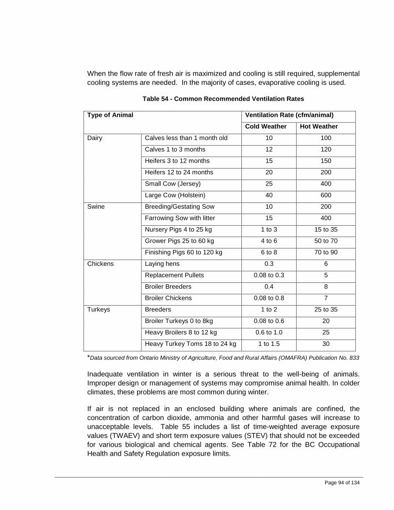
Page 94 of 134
When the flow rate of fresh air is maximized and cooling is still required, supplemental cooling systems are needed. In the majority of cases, evaporative cooling is used.
Table 54 - Common Recommended Ventilation Rates
Type of Animal Ventilation Rate (cfm/animal)
Cold Weather Hot Weather
Dairy Calves less than 1 month old 10 100
Calves 1 to 3 months 12 120
Heifers 3 to 12 months 15 150
Heifers 12 to 24 months 20 200
Small Cow (Jersey) 25 400
Large Cow (Holstein) 40 600
Swine Breeding/Gestating Sow 10 200
Farrowing Sow with litter 15 400
Nursery Pigs 4 to 25 kg 1 to 3 15 to 35
Grower Pigs 25 to 60 kg 4 to 6 50 to 70
Finishing Pigs 60 to 120 kg 6 to 8 70 to 90
Chickens Laying hens 0.3 6
Replacement Pullets 0.08 to 0.3 5
Broiler Breeders 0.4 8
Broiler Chickens 0.08 to 0.8 7
Turkeys Breeders 1 to 2 25 to 35
Broiler Turkeys 0 to 8kg 0.08 to 0.6 20
Heavy Broilers 8 to 12 kg 0.6 to 1.0 25
Heavy Turkey Toms 18 to 24 kg 1 to 1.5 30
*Data sourced from Ontario Ministry of Agriculture, Food and Rural Affairs (OMAFRA) Publication No. 833
Inadequate ventilation in winter is a serious threat to the well-being of animals. Improper design or management of systems may compromise animal health. In colder climates, these problems are most common during winter.
If air is not replaced in an enclosed building where animals are confined, the concentration of carbon dioxide, ammonia and other harmful gases will increase to unacceptable levels. Table 55 includes a list of time-weighted average exposure values (TWAEV) and short term exposure values (STEV) that should not be exceeded for various biological and chemical agents. See Table 72 for the BC Occupational Health and Safety Regulation exposure limits.

Page 95 of 134
Adjusting the ventilation system for severe winter weather and not increasing ventilation for milder winter weather are occasional causes of compromised air quality problems in barns. Cold barns with manually-controlled natural ventilation are particularly susceptible to this problem.
Table 55 – Allowable Biological and Chemical Agents Exposure Levels in Barns
Gas TWAEV STEV Typical Agricultural Operations with Concentrations Exceeding TWAEV
Carbon Dioxide (ppm) 5,000 30,000 Swine, poultry
Ammonia
(ppm) 25 35 Poultry, swine and dairy calves
Hydrogen Sulphide
(ppm) 10 15 During manure agitation for swine, dairy and
poultry
Carbon Monoxide (ppm)
USA (86/87)
35
40
400
400 Poultry and swine facilities when unvented fuel
fired heaters are maladjusted
Nitrogen Dioxide (ppm) 3 5 Inside silos after filling
Grain Dust (mg/m3) 4 - Livestock feed rooms and grain centres
Total Dust (mg/m3) 10 - Most barns after animal feeding
Respirable Dust
(mg/m3) USA (86/87) 5 1 -
2 Table data provided by: Farmstead Planning, Health and Safety Specialist/Alfred College; J.A. Munroe - Centre for Food and Animal Research/Agriculture and Agri-Food Canada, written by Yves Choinière
Ammonia is a product of protein metabolism. Nitrogen wastes in urine and manure convert to ammonia. Ammonia evaporates into the air at higher rates in warm/moist conditions. Ammonia irritates the respiratory system. Increased stress due to constant exposure to ammonia can weaken an animal’s ability to fight disease.
Hydrogen sulfide is produced from animal and organic wastes. It has a recognizable rotten egg smell. It is a respiratory irritant that causes an increased risk of respiratory disease. High exposure levels can be fatal.
Endotoxins are from bacteria and are highly immunogenic. Inhalation of endotoxins causes an immune reaction similar to disease. Inflammation occurs and reduces the body’s ability to fight diseases.
Moisture levels are easy to observe and directly affect the levels of most contaminants, primarily during the cold weather heating season when ventilation rates are low. A
Page 96 of 134
target level for barn relative humidity in cold weather is 55%-75% to minimize pathogens.
Many pathogens survive longer in moist, warm conditions. Viruses such as parainfluenza-3 virus, porcine reproductive and respiratory syndrome (PRRS), recombinant bovine respiratory syncytial virus (BRSV), infectious bovine rhinotracheitis (IBR), bovine viral diarrhea (BVD), rotavirus, coronavirus; and bacteria such as pasteurella multocida, mannheimia haemolytica, mycoplasma bovis, and histophilus somnus are examples. High levels of viral particles and bacteria suspended in the air will increase the risk of infection.
There are also pathogens that can survive at low levels of relative humidity. Lower moisture levels also affect respiratory function and dry out the mucous membranes, allowing easier pathways into the animals’ bodies.
Most airborne dust in a livestock or poultry facility is in the respirable range (particle size less than 5 μm). Ventilation systems help reduce airborne dust within a barn; however, increased air flow does not always result in reduced dust levels. A low ventilation rate results in higher humidity levels. Increased moisture levels in a barn will reduce dust generation rates. It is important to maintain the target relative humidity.
5.0 System Design 5.1 System Design Flowcharts
In order to provide a visual guideline for farmers as they work with ventilation designers, two design flowcharts are presented and include questions to ask and considerations to examine. The charts include the most commonly used technology in the market today. The first flow diagram focuses on ventilation system design, while the second suggests mitigation tactics for odour, noise, dust and biosecurity.

Page 97 of 134
5.1.1 Ventilation System Design
Ventilation System Design Process
Building/Room Dimensions: • Height, Length, Width • Barn Orientation to prevent prevail-
ing winds
L
W
H
Perimeter Type: What is the perimeter type? Level and Type of Insulation?
Below Floor Manure Storage
Shallow Pit < 4’
Deep Pit > 4’
Foundation ~2’ or to frost line
Slab Solid
Foundation
Roof Height/Type: What style of roof?
What kind of attic insulation?
Flat Scissor Open
Proper insulation and attic venting required
Proper insulation and attic venting
required
-No specific attic venting required
-Proper insulation
Attic Roof Ventilation—Part of Animal Ventilated Space
Net Open Area of Soffits and Peak Vents If attic is a part of ventilation system (flat/scissor) then
opening to attic must account for ventilation
Zones: # of Ventilation Controlled Zones in one air space
Each zone = L x W
Attic Roof Ventilation—Not a Part of Animal Ventilated Space
Net Open Area of Soffits and Peak Vents Attic Ventilation Fan Moisture and Temperature Control Only
Pens: # of pens and animals in a zone or room, dimensions
of each pen, L x W # of animals/birds per pen

Page 98 of 134
Ventilation Design Analysis Data Inputs:
Information Required
Note: design must account for all sources of moisture, CO2 and animal heat
All output values have to be at minimum 4 air changes / hour to maximum 1 air change a minute
Minimum Maximum
# of animals
Average Weight
Temp (inside)
RH (inside)
Temp (outside)
RH (outside)
CO2 (inside) N/A
Wall, Ceiling, Floor, Doors, Win-dows, Foundation Insulation Val-
ues (R Values)
Ventilation Analysis Output Total Ventilation Exhaust, Fresh Air Intake, Heating Requirements
Minimum Winter
Maximum Summer
Lower than 4 air changes per
hour
Determine if airflow should be increased
Use as stated
Use as stated
Increase and recalculate winter heating requirements
Higher than Appendix B
Value?
Use Appendix
B Use Output Value
Less than one air change per
minute
Increase to 1 air change/minute
Consider decreasing to 1 air change/
minute
AIR INLET DESIGN
NO
NO
YES
YES
NO
YES
NO
YES
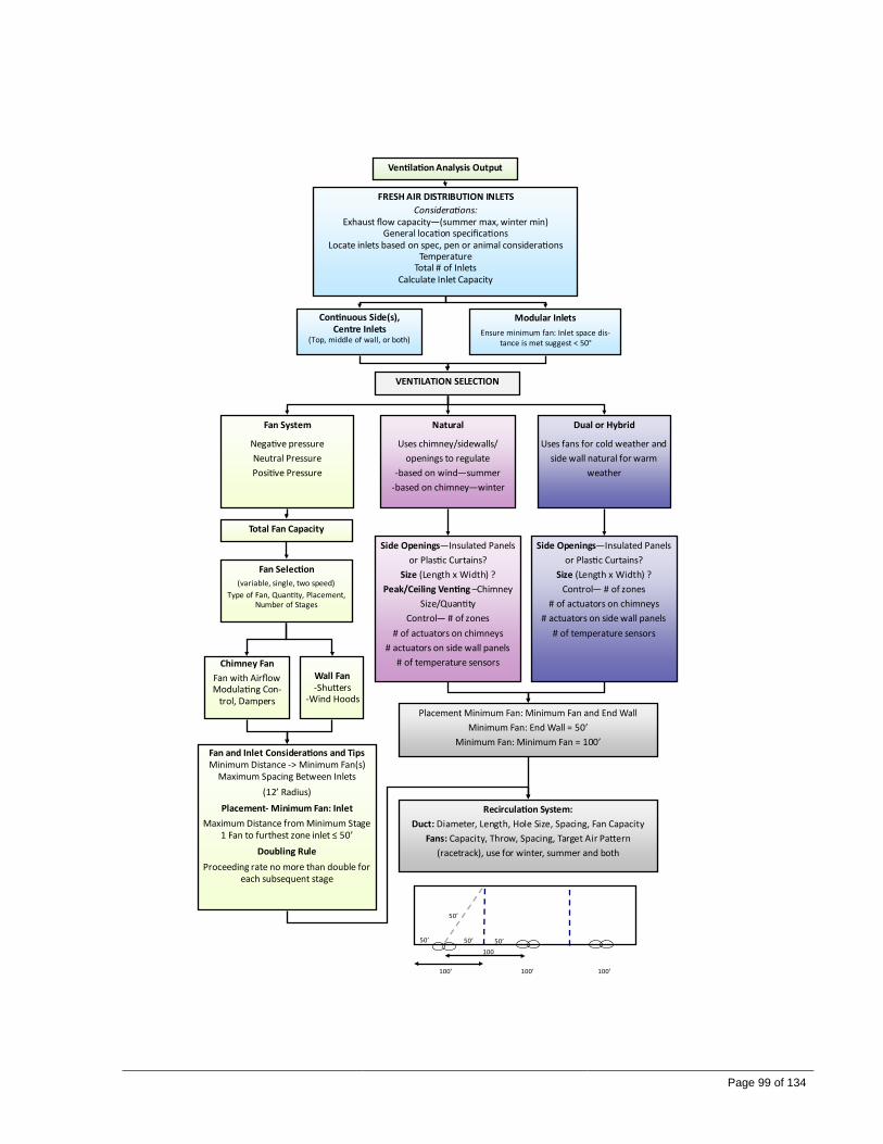
Page 99 of 134
VENTILATION SELECTION
Fan System
Negative pressure Neutral Pressure Positive Pressure
Natural
Uses chimney/sidewalls/openings to regulate
-based on wind—summer -based on chimney—winter
Dual or Hybrid
Uses fans for cold weather and side wall natural for warm
weather
Ventilation Analysis Output
FRESH AIR DISTRIBUTION INLETS Considerations:
Exhaust flow capacity—(summer max, winter min) General location specifications
Locate inlets based on spec, pen or animal considerations Temperature
Total # of Inlets Calculate Inlet Capacity
Continuous Side(s), Centre Inlets
(Top, middle of wall, or both)
Modular Inlets Ensure minimum fan: Inlet space dis-
tance is met suggest < 50°
Total Fan Capacity
Fan Selection (variable, single, two speed)
Type of Fan, Quantity, Placement, Number of Stages
Wall Fan -Shutters
-Wind Hoods
Chimney Fan Fan with Airflow Modulating Con-
trol, Dampers
Fan and Inlet Considerations and Tips Minimum Distance -> Minimum Fan(s)
Maximum Spacing Between Inlets (12’ Radius)
Placement- Minimum Fan: Inlet Maximum Distance from Minimum Stage
1 Fan to furthest zone inlet ≤ 50’ Doubling Rule
Proceeding rate no more than double for each subsequent stage
Side Openings—Insulated Panels or Plastic Curtains?
Size (Length x Width) ? Peak/Ceiling Venting –Chimney
Size/Quantity Control— # of zones
# of actuators on chimneys # actuators on side wall panels
# of temperature sensors
Side Openings—Insulated Panels or Plastic Curtains?
Size (Length x Width) ? Control— # of zones
# of actuators on chimneys # actuators on side wall panels
# of temperature sensors
Placement Minimum Fan: Minimum Fan and End Wall Minimum Fan: End Wall = 50’
Minimum Fan: Minimum Fan = 100’
Recirculation System: Duct: Diameter, Length, Hole Size, Spacing, Fan Capacity
Fans: Capacity, Throw, Spacing, Target Air Pattern (racetrack), use for winter, summer and both
50’ 50’
100’
100
100’ 100’
50’
50’
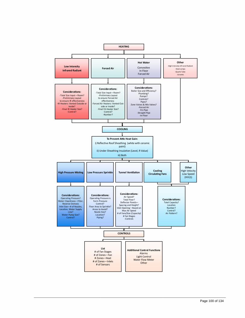
Page 100 of 134
HEATING
Low Intensity Infrared Radiant
Forced Air
Hot Water
Convective In Floor
Forced Air
Other -High Intensity Infrared Radiant
-Heat Lamps -Quartz Tube
-Ceramic
Considerations: Boiler Size and Efficiency?
Plumbing? Pumps?
Controls? Pipes?
Zone Valves & Mix Valves? -Forced Air
-Fin Pipe -Straight Pipe
-In-Floor
Considerations: -Total Size Input—Room?
-Preliminary Layout to ensure IR effectiveness
-IR Heaters: Vented Outside or Inside?
-Final IR Heater Size? -Control?
Considerations: -Total Size Input—Room?
-Preliminary Layout to ensure Forced Air
effectiveness -Forced Air Heaters: Vented Out-
side or Inside? -Final FA Heater Size?
-Control? -Number?
COOLING
To Prevent Attic Heat Gain: i) Reflective Roof Sheathing (white with ceramic
paint) ii) Under Sheathing Insulation (Level, R Value)
iii) Both
High Pressure Misting Low Pressure Sprinkle
Other High Velocity Low Speed
(HVLS)
Tunnel Ventilation
Considerations: Air Speed? Total Floor?
Deflector Panels—Spacing and Height?
Inlet Opening—Based on Max Air Speed
# of Fans/Size (Capacity) # Fan Stages
-Controls
Considerations: Operating Pressure is
Farm Pressure Control?
Floor Area to Sprinkle? Areas to Avoid?
Nozzle Size? Location?
Piping?
Considerations: Operating Pressure?
Water Cleanliness—Filter, Reverse Osmosis
Inlet Size—# of Nozzles, Location, Water Supply
Line? Water Pump Size?
Control?
CONTROLS
List # of Fan Stages # of Zones—Fan # Zones—Heat
# of Zones—Inlets # of Sensors
Additional Control Functions Alarms
Light Control Water Flow Meter
Other
Cooling Circulating Fans
Considerations: Total Capacity?
Location Number? Control?
Air Pattern?

Page 101 of 134
5.1.2 Odour, Noise, Dust and Biosecurity
NOISE
Noise Control Earth Berms
What is it covered with?
Noise Barrier Fence
Vegetative Buffers What types of vegetation and variation?
Considerations: Inside:
Ductwork systems—appropriate velocity? Air intake—generate noise?
Location of fans? Outside:
Are there adjacent neighbours? Are there ducted sound attenuators?
Windbreak Wall
ODOUR MITIGATION AND BIOSECURITY
Air Filtration Bio-Filtration Scrubbers UV Light
DUST
Misting Showers
DUST
Building Electrostatic Charge
Considerations: Odour retrofits also applicable in dust mitigation
Considerations: Purpose of odour management? How effective does it need to be?
Cost and frequency of maintenance and upkeep? Airborne viruses that need to be monitored?
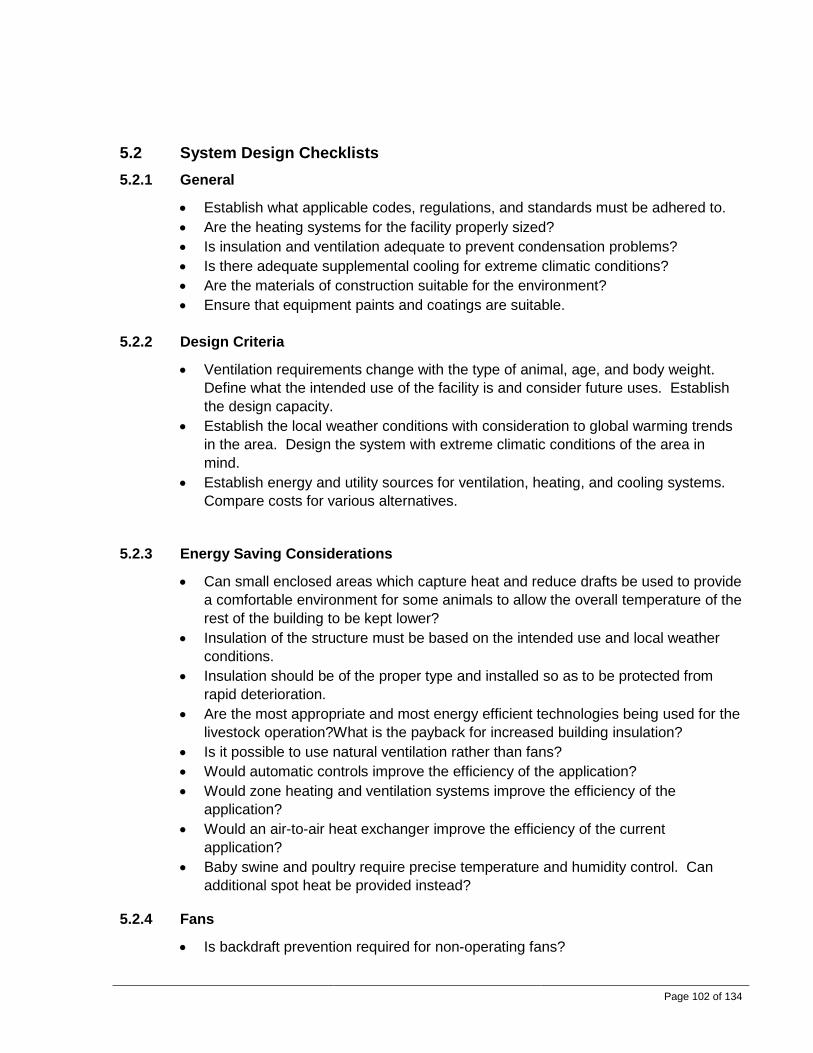
Page 102 of 134
5.2 System Design Checklists 5.2.1 General
• Establish what applicable codes, regulations, and standards must be adhered to. • Are the heating systems for the facility properly sized? • Is insulation and ventilation adequate to prevent condensation problems? • Is there adequate supplemental cooling for extreme climatic conditions? • Are the materials of construction suitable for the environment? • Ensure that equipment paints and coatings are suitable.
5.2.2 Design Criteria
• Ventilation requirements change with the type of animal, age, and body weight. Define what the intended use of the facility is and consider future uses. Establish the design capacity.
• Establish the local weather conditions with consideration to global warming trends in the area. Design the system with extreme climatic conditions of the area in mind.
• Establish energy and utility sources for ventilation, heating, and cooling systems. Compare costs for various alternatives.
5.2.3 Energy Saving Considerations
• Can small enclosed areas which capture heat and reduce drafts be used to provide a comfortable environment for some animals to allow the overall temperature of the rest of the building to be kept lower?
• Insulation of the structure must be based on the intended use and local weather conditions.
• Insulation should be of the proper type and installed so as to be protected from rapid deterioration.
• Are the most appropriate and most energy efficient technologies being used for the livestock operation?What is the payback for increased building insulation?
• Is it possible to use natural ventilation rather than fans? • Would automatic controls improve the efficiency of the application? • Would zone heating and ventilation systems improve the efficiency of the
application? • Would an air-to-air heat exchanger improve the efficiency of the current
application? • Baby swine and poultry require precise temperature and humidity control. Can
additional spot heat be provided instead? 5.2.4 Fans
• Is backdraft prevention required for non-operating fans?

Page 103 of 134
• Size fans correctly for the required building ventilation. Fans that are larger than necessary will waste energy; however, it is usually better to select slightly oversized rather than undersized fans. A safety factor is needed in case any one fan fails to operate.
• Select fans that are energy efficient. There is a significant difference between the best and worst performing fans.
• Fans with diffusers or discharge cones are more efficient than fans without them. • Consider prevailing winds. Fans located on the wall opposite the prevailing wind
will improve its efficiency. • Large diameter fans are usually more efficient than smaller diameter fans. • The fans should be wired by competent electricians and in accordance with
applicable codes.
5.2.5 Distribution of Fresh Air into the Barn
• The uniformity of air distribution depends on the location, design and adjustment of the air inlets. Will the design achieve uniform air distribution in the barn with no ‘dead spots’?
• Air inlet size is critical to proper functioning of the ventilation system. • If cold air is allowed to flow into a warm area, it may cause fog. Proper mixing and
circulation of the air during cold weather are important. • Select appropriate velocities for air inlets. • Are fire dampers required? • Has the ducting been properly sized? Check design air velocities and pressure
losses through duct, air inlets and outlets.
5.2.6 Air Filtration
• What types, sizes, and quantity of filters are needed? • What is the lifespan of the filters under design conditions? • Are the fans adequately sized to handle the pressure loss through the filters?
Careful consideration is necessary when determining the amount of filter area required for air inlets. To achieve a low pressure loss across a filter, the face velocity is usually much lower than catalogue ratings.
5.2.7 Maintainability
• Are entry doors and walkways required in the attic to service and replace ceiling inlet filters?
• Are inspection doors provided on ducting and equipment?

Page 104 of 134
5.2.8 Controls
• Fans are usually controlled by thermostats and/or timers. A single-stage thermostat will control one or more single-speed fans by activating the fan when the temperature rises.
• Timers are used for intermittent operation of one or more fans, especially in cold weather. Most timers operate fans on an on/off cycle to approximate the air delivery of a continuous fan. A continuously operating fan at a low speed would not provide the air velocities required for proper mixing.
• A suitable alarm system and/or electric generating equipment should be available in case of power failure.
• Energy savings can be achieved through zoned climate control. • Automatically controlled ventilation systems reduce unnecessary fan operation and
provide more uniform climate control. Variable speed controllers can be used to control the amount of air exhausted.
• Are thermostats and humidistats located properly to not be affected by drafts and direct sunlight?
• Are room air velocity sensors required?
5.2.9 System Supplier Documentation Requirements
The following list may serve as a checklist for documents that may be desirable from a system supplier.
• General arrangement drawings • Piping and instrument diagrams; ventilation flow diagrams • Bill of materials • Equipment specifications; vendor catalogue sheets • Centrifugal pump performance curves • Certified fan performance curves • Surface preparation and painting specifications • Electrical connection diagrams • Electrical / instrument panel detail drawings • Electrical cable schedule • Operating instructions • Safety instructions • Maintenance instructions • Troubleshooting guide • Recommended spare parts for commissioning and for operation • Balance and commissioning report including comparisons of design and actual air
flows, temperatures, pressures, water flows, power consumption, etc.

Page 105 of 134
5.3 Sample System Design Software Application Ventilation system design software should show the inputs and design outputs. A copy of this information should be provided to the farmer with the final design documentation. An example of an analysis tool is available from the Ontario Ministry of Agriculture, Food and Rural Affairs (OMAFRA) website at the following link: http://www.omafra.gov.on.ca/english/products/environment.html
This particular example illustrates a broiler chicken barn. The barn houses 12,000 broiler chicks to a market weight of 2.2 kg. Space allocation is 0.9375 ft2/bird.
Input Data: The input data table from Figure 54 Input Data illustrates all the inputs that should be supplied by the farmer to the ventilation designer. This includes farm location, livestock specifications, building size and insulation parameters, ventilation considerations and energy costs.

Page 106 of 134
Figure 54 Input Data

Page 107 of 134
Ventilation Summary: The ventilation summary entries in Figure 55 below are tabular outputs from the ventilation software resulting from the given input conditions supplied in the table above. Two example scenarios are shown for broiler chickens, one at low weight (Run 1), and the other at finishing weight (Run 2). The required fan capacities for increasing temperatures ranging from -30°F to 90°F are shown. Fans are to be sized for the required fan capacity (cfm) listed as the temperature increases to ensure that there is adequate ventilation capacity for the maximum temperatures indicated.
Figure 55 - Ventilation Summary

Page 108 of 134
Ventilation Graph: The graphical representation in Figure 56 below shows the required fan capacity in cfm versus the temperature listed in the previous “Ventilation Summary” sheet. Note the rapid change in CFM requirements between 60-70 degrees Fahrenheit. This transition will require careful consideration by the designer to ensure a smooth increase in air flow rates to maintain indoor environment and minimal unwanted drafting.
Figure 56 - Ventilation Graph

Page 109 of 134
Ventilation Chart: The chart in Figure 57 below considers more detailed ventilation requirements such as moisture, heat, ventilation rate, and fan capacity as output functions for selected temperatures. It also provides the inlet opening setting in inches and the heat requirement in BTU/hr for a given temperature condition, under the requirement for CO2 levels to remain within a reasonable range. Furthermore, the system identifies when there are too few air changes (i.e., < 4 air changes / hour) and when the rate of air changes (> 1 air changes/min) is too high. All these parameters come into play when considering appropriate fan sizing and staging.
Figure 57 - Ventilation Chart

Page 110 of 134
Heat Balance Chart: With the given building and insulation inputs provided in the planning phase as shown in Figure 54 above, the ventilation designer should provide a heat balance chart as shown in Figure 58 below, indicating both the heat gained by the animals and the heat lost by the building to the surroundings. Any imbalance will result in animals being heat stressed if the overall heat gain is too large or stressed by excessively cold temperatures if there is too much heat loss to the surroundings. Steps to mitigate any seasonal and livestock variation should be identified by the designer and provided in detail.
Figure 58 - Heat Balance Chart

Page 111 of 134
Internal Air Circulation – Non Duct: Once all the ventilation design steps outlined above are addressed, the designer should then provide, as shown in Figure 59 below, the results of calculations for the minimum and maximum total internal circulation requirements and the cfm output required per fan. In this scenario, a minimum of 4 fans and a maximum of 6 fans were chosen. Layout considerations for the fan placement to provide even air distribution based on the barn dimensions need to be provided.
Figure 59 - Internal Air Circulation

Page 112 of 134
Tunnel Ventilation Chart: In scenarios where tunnel ventilation is selected as a viable method, the designer must provide the sidewall opening size and the air speed that will be provided as shown in Figure 60 below.
Figure 60 - Tunnel Ventilation Chart

Page 113 of 134
6.0 Maintenance and Monitoring Checklists The purpose of this section is to provide guidance for the development of checklists associated with routine maintenance requirements of barn ventilation equipment.
As a general rule of thumb, incorporating a routine ventilation system maintenance schedule as part of farm operation is usually less costly than replacing equipment that fails prematurely.
It is important to maintain a maintenance log for each piece of equipment. The date, type of work done, and person having done the work should be included in a record keeping system.
The personnel performing the maintenance work must be suitably qualified. It is the responsibility of maintenance personnel to ensure that suitable safety procedures are followed during maintenance procedures.
In some cases, vendor instructions may be insufficient. If these are not available, suitable maintenance instructions should be developed to help ensure systems continue to function as intended. Maintenance personnel should be provided with checklists outlining routine maintenance requirements of the mechanical equipment. The checklists should include descriptions and suggested frequencies of all maintenance procedures.
Any worn or defective components should be replaced only with vendor- or engineer-approved parts.
6.1 General
• For final balancing and commissioning of the systems, the building should be filled with poultry or livestock to the design capacity.
• Check the pressure of the building relative to the outdoors. • Check/monitor barn temperature and humidity levels. • Are the heating systems functioning properly? • Are thermostats and humidistats properly adjusted and functioning properly?
6.2 Fans
• Check belt tension and condition of drive components. Reset the tension or replace drive components when necessary. Ensure set-screws are tight and keys are in place on sheaves. Loose fan belts can slip and reduce fan performance. If possible, install self-tensioning devices on fan drives to reduce maintenance requirements.
• Lubricate motor bearings. Do not lubricate excessively. • Inspect fan wheel and shaft condition; check vibration levels.

Page 114 of 134
• Fan wheel and protective guards must be clean. Clean fan assemblies are more efficient.
• Check structural integrity of entire unit including housing, motor cover, etc. Ensure all fasteners are tight.
• Inspect drive motor. Ensure vent openings are clear and motor is clean. Clean motors operate cooler and have prolonged life. Check amperage draw and ensure it is within acceptable range. A small temperature gauge located on a motor is a useful tool for indicating if it is functioning properly.
6.3 Heaters
• Start the heating system periodically to help prevent moisture from infiltrating heating coils.
• Electrical Inspection: all electric connections to contactors should be checked and tightened.
• Visual Inspection: signs of problems include accumulation of dust on the heating elements, signs of overheating on the heater frame, and traces of water or rust on the control box.
• Check all fuses, the resistance to ground for each circuit, the resistance phase to phase for each circuit, the tightening of connections at all contactors and heating elements
• Check all piping and pumps • Check all venting
6.4 Ductwork • Check structural integrity of ducting, insulation, and hangers. • Ensure all fasteners are tight. • Ensure that all manual balancing dampers are in their marked position when the
system was originally balanced. Confirm that all supply diffusers and return air grills are in good condition.
• Check internal cleanliness; clean as required. • Ventilation inlets need to be cleaned and adjusted for proper operation. Dirty
louvers and dampers that do not open fully can reduce air flow. These should be cleaned and lubricated.
• Monitor pressure loss across filters and change or clean the filters as required. Inspect filter installation to ensure they are properly sealed and not damaged. Shut down fans during filter change-out to prevent downstream contamination.
• Filter banks can collapse if excessively loaded. • Contaminants will accumulate inside ducts. Areas with restricted airflow or areas
with moisture are more prone to this. • Biological pollutants can be prevented by good maintenance. Keep ductwork and
equipment in good, clean, dry working order.

Page 115 of 134
• Duct leakage is to be avoided. It can waste energy because leaks can occur at loose supply duct connections and bleed air back into the return plenum or outdoors. Leaks in return air ducts that pass through unconditioned spaces or underground can draw in contaminants.
• Air intake screens and grilles can become fouled and plugged. • Hoarfrost can block intakes and mixing chambers during winter. • Outdoor contaminants can be brought indoors through the ventilation system’s air
intake system. • Wet surfaces should be drained and maintained to prevent microbial growth. • Internal duct surfaces should not be allowed to become moist from water spray or
condensation.
7.0 State of the Industry 7.1 Ventilation Survey
We interviewed the following individuals to help formulate this report.
Table 56 List of Survey Respondents
Name and Position Company Name and Location Description of Services
Albert de Lange J & D Farmers Dairy Service, Abbotsford
Supply, install, retrofit and service of dairy ventilation systems
Berry Binnendyk, Service & Sales
Precision Farm Supplies Ltd., Abbotsford
Design, supply, build, retrofit and service of dairy, poultry and hog ventilation systems
Ben Meinen, Owner Meinen Brothers Agri Services, Agassiz
Design, supply, build, retrofit and service of dairy ventilation systems
David Jonkman, President
Jonkman Equipment, Abbotsford
Design, supply, build, retrofit and service of dairy, poultry and hog ventilation systems
Dr. Chris Byra Greenbelt Swine Veterinary Services Swine Veterinary Services
Dr. John Dick Greenbelt Veterinary Services Dairy Veterinary Services
Dr. Neil Ambrose Ambrose Poultry Consulting Ltd. Poultry Veterinary Services
Dr. Stewart Ritchie Canadian Poultry Consultants Ltd. Poultry Veterinary Services
John Fleming, Ventilation Designer
Artex Barn Solutions, Abbotsford
Design, supply and retrofit of dairy ventilation systems

Page 116 of 134
Leo Apperloo, Director United Agri Systems, Abbotsford
Design, supply, build, retrofit and service of dairy and poultry ventilation systems
The intent of the survey was to establish what ventilation systems are installed in existing barns for each major animal type and what ventilation systems are being installed in new barns to identify current trends. The respondents were instructed to provide details on British Columbia only, as some suppliers work both nationally and internationally. The interviews were preformed primarily over the phone, and took between 30 and 50 minutes.
Table 57 correlates the description of a type of ventilation system or equipment with the frequency percentage to quantify the survey results in the survey summary tables that follow.
Table 57 Survey Results Descriptors
Descriptor Perceived Share of the Industry
Not used 0 % Rare 0 - 10% Uncommon 10% - 35% Common 35% - 60% Very common 60% - 85% Predominant 85% - 100%
7.1.1 Dairy Ventilation Trends
Six suppliers and vets active in the BC dairy industry were interviewed over the phone and one dairy producer responded to the online SurveyMonkey tool. Each respondent was asked how common they thought different types of ventilation systems were used for both existing and new barns. The types were recorded for calf, heifer/dry and milking barns separately as each animal type has a unique set of environmental requirements. Results of the survey are presented below.
Table 58 Survey Results – Ventilation Systems for Existing BC Dairy Barns
Calf Barns Heifer/Dry Cow Barns Milking Barns Tunnel Rare Rare Rare Negative Pressure Rare Rare - Neutral Pressure Rare - - Natural Very Common Predominant Predominant Combined Rare Rare Rare Pit - - - Other- Positive Rare - -

Page 117 of 134
Table 59 Survey Results – Ventilation Systems for New BC Dairy Barns
Calf Barns Heifer/Dry Cow Barns Milking Barns Tunnel Rare Rare Rare Negative Pressure Rare Rare Rare Neutral Pressure - - - Natural Predominant Predominant Predominant Combined - - - Pit - - - Other- Positive Uncommon - -
As can be seen in Table 58 and Table 59, the predominant ventilation system across the board in dairy barns is natural ventilation. Tunnel ventilation is becoming more common in milking barns to improve cooling, and was seen as a technology that could benefit the BC Dairy industry. It is worth noting that positive pressure systems for calf barns were repeatedly recommended to improve calf health; calves are very sensitive to drafts, so these systems use a large duct with 100% outdoor air to provide an even supply of fresh air (see Figure 15).
Table 60 Survey Results – Cooling Systems for BC Dairy Barns
Calf Barns Heifer/Dry Cow Barns Milking Barns High Pressure Mist - Rare Rare Sprinklers - Rare Common EvaporativeCooling Pads
- - -
Axial Fans - Rare Uncommon HVLS Fans - Rare Uncommon Other - - -
Table 61 Survey Results – Common Dairy Ventilation Problems
Question: Are there any systems you see that you would not recommend or do you see common problems in the dairy industry?
1 Overhead fans, especially high volume low speed (HVLS) types installed over center drive-through alley, leading to low air speeds where the animals actually are. These fans can also work against currents set up by air exchange fans.
2 Calf barns with poor/inadequate ventilation. 3 Calf barns with too much ventilation in negative pressure barns. 4 Buildup of dust in ducted systems. 5 Cooling using in floor heating systems; animals have a comfort zone and floor
can be too cool or uncomfortable.

Page 118 of 134
Table 62 Survey Results – Promising New Ventilation Technologies for Dairy
Question: Are you aware of any new technologies that could be applied in BC? 1 Ducted positive pressure calf barns. 2 Air-to-air heat exchangers. 3 Tunnel ventilation for cooling of large scale dairy barns (visited tunnel ventilated
barn in US serving 16,000 cows). 4 Better controls for calf barns, including temperature and airspeed.
Based on the survey responses, the two greatest opportunities for improvement are calf barn design and increased cooling for lactating dairy cows.
7.1.2 Poultry Ventilation Trends
Four suppliers and vets active in the BC poultry industry were interviewed over the phone. Each respondent was asked how common they thought different types of ventilation systems were used for both existing and new barns. The types were recorded for layers, turkeys and broilers separately as each bird type has a unique set of environmental requirements. Turkeys are often raised in two or three different stages, with starter, grower and finisher barns; however, turkey was consolidated into a single category. Results of the survey are presented below.
Table 63 Survey Results – Ventilation Systems for Existing BC Poultry Barns
Layers Turkeys Broilers
Tunnel Uncommon Rare Common Negative Pressure Rare Very Common Very Common Neutral Pressure Rare Rare Rare Natural Rare Common - Combined Rare Rare - Pit Very Common - - Other - - -
Table 64 Survey Results – Ventilation Systems for New BC Poultry Barns
Layers Turkeys Broilers Tunnel Common Common Very Common Negative Pressure Very common Common Uncommon Neutral Pressure - - Natural - Uncommon Combined - Rare Pit Rare - Other - -

Page 119 of 134
As can be seen in Table 63 and Table 64, the primary ventilation system for layer barns is pit ventilation; however this is changing as older barns are replaced with newer barns. Tunnel and negative pressure (cross flow) ventilation systems are becoming more common. For turkey barns, the majority of starter barns operate under negative pressure, with natural ventilation more common for grower/finisher barns. The trend for turkey barns is towards tunnel and negative pressure ventilation. Broiler barns almost exclusively use forced air ventilation, with tunnel ventilation showing up in the last few years. Mike Czarick from the University of Georgia was mentioned repeatedly as a champion of tunnel ventilation, and has been consulting some suppliers/producers with designs for barns. As one respondent mentioned, tunnel ventilation is relatively inexpensive to incorporate into new construction and, furthermore, it seems to work well. Much information on the subject, along with associated design tools, are readily available on the University of Georgia’s Poultry website at the following link: https://www.poultryventilation.com/.
Table 65 Survey Results – Cooling Systems for BC Poultry Barns
Layers Turkeys Broilers High Pressure Mist Common Uncommon Common Sprinklers - - - Evaporative cooling Pads
Uncommon Rare Common
Axial Fans Rare Uncommon Rare HVLS Fans Rare Uncommon Rare Other - - - It is worth noting that a number of producers were said to be using sprinklers on the barn roof for cooling. This should be an indication that the ventilation system is inadequate. Considerable volumes of water are required to achieve cooling in this manner. In addition, roof cooling is typically messy, costly and not very effective.
Table 66 Survey Results – Common Poultry Ventilation Problems
Question: Are there any systems you see that you would not recommend? 1 Would not recommend natural ventilation, even for turkeys. 2 Mickey mouse combinations of systems, which is the result of listening to too
many opinions.
Table 67 Survey Results – Promising New Ventilation Technologies for Poultry
Question: Are you aware of any new technologies that could be applied in BC? 1 Air-to-air heat exchangers. 2 Filters or scrubbers on exhaust, especially near urban areas.

Page 120 of 134
Based on the survey responses, the two greatest opportunities for improvement in the poultry industry are training and consolidated research and applications that are suitable for BC.
7.1.3 Swine Ventilation Trends
There are only fifteen swine operations in the province of BC, three of which are grow/finish operations, with the remaining eleven being farrow to finish. One supplier, one vet and one producer were each interviewed. Each respondent was asked how common they thought different types of ventilation systems were for both existing and new barns. The types were investigated for breeding/gestation, farrow, nursery, grow and finishing operations separately. As only one new swine barn has been built in recent memory, results are tabulated below for existing barns only.
Table 68 Survey Results – Ventilation Systems for Existing BC Swine Barns
Breeding/ Gestation
Farrow Nursery Grow Finish
Tunnel - - - - - Negative Pressure
Very common
Very Common
Very Common
Very Common
Rare
Neutral Pressure - - - - - Natural Rare Rare Rare Uncommon Common Combined Rare Rare Rare Rare Rare Pit Uncommon Uncommon Uncommon Rare Common Other - - - - -
As can be seen in Table 68, the primary ventilation system in swine barns is negative pressure ventilation, with pit ventilation common in older barns.
Table 69 Survey Results – Cooling Systems for Existing BC Swine Barns
Breeding/ Gestation
Farrow Nursery Grow Finish
High Pressure Mist
- Rare - - -
Sprinklers Common Common Rare Common Common Evaporative Cooling Pads
- - - - -
Axial Fans Rare Rare Rare Rare Rare HVLS Fans Rare Rare Rare Rare Rare Other - - - - -

Page 121 of 134
Table 70 Survey Results – Common Swine Ventilation Problems
Question: Are there any systems you see that you would not recommend? 1 Low pit ventilation rates that cause ammonia concentrations to exceed 25 ppm.
Table 71 Survey Results – Promising New Ventilation Technologies for Swine
Question: Are you aware of any new technologies that could be applied in BC? 1 Virus filtration on exhaust air could help prevent the spread of diseases such as
porcine epidemic diarrhea (PED).

Page 122 of 134
8.0 Review of Relevant Literature Regarding Ventilation, and Control of Dust, Odour, and Noise
8.1 Government Handbooks – Canada
Canada Plan Service • Plan 2000 Dairy Cattle Housing and Equipment • Plan 3000 Swine Housing and Equipment • Plan 5210 Layer Housing • Plan 5310 Broiler Housing • Plan 5320 Pullet Housing • Plan 9700 Fan Ventilation Principles and Rates • Plan 9702 Troubleshooting Livestock and Poultry Ventilation Problems • Plan 9705 Selecting Fans for Livestock Buildings • Plan 9707 Protecting Workers in Livestock Buildings from Dust and Gas • Plan 9735 Hot Water Heating
Level of Accuracy: Moderate Relevancy: High Usefulness: Moderate
The Canada Service Plan is a source for basic information on ventilation topics for all livestock facilities, and includes recommended temperature / humidity ranges, as well as ventilation rates in cfm/animal for different types of livestock and different housing types. Plans for barns can also be ordered.
The BC Ministry of Agriculture has made many of the Canada Service Plan leaflets and plans available on their website. The information is dated, much of it from the mid 1980’s. There is no mention of tunnel ventilation systems for poultry barns, which is becoming amore common system.
Ontario Ministry of Agriculture, Food and Rural Affairs. 2010. Publication 833 “Ventilation for Livestock and Poultry Facilities”. Toronto: Ministry of Agriculture, Food and Rural Affairs.
Level of Accuracy: High Relevancy: High Usefulness: High
Detailed handbook providing information on ventilation principles, barn insulation, fresh air inlets, fan systems, ventilation controls, heating, cooling, attic ventilation, natural ventilation, energy conservation, commissioning, and maintenance. It includes an appendix with recommended ventilation rates.
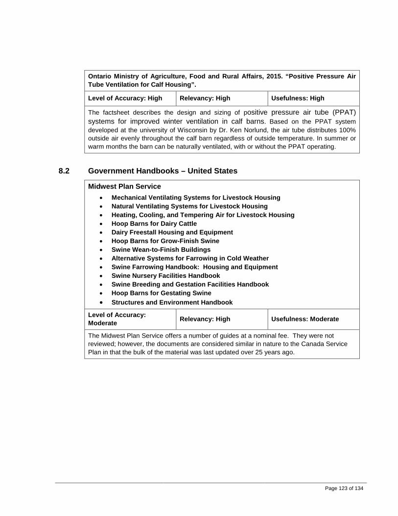
Page 123 of 134
Ontario Ministry of Agriculture, Food and Rural Affairs, 2015. “Positive Pressure Air Tube Ventilation for Calf Housing”.
Level of Accuracy: High Relevancy: High Usefulness: High
The factsheet describes the design and sizing of positive pressure air tube (PPAT) systems for improved winter ventilation in calf barns. Based on the PPAT system developed at the university of Wisconsin by Dr. Ken Norlund, the air tube distributes 100% outside air evenly throughout the calf barn regardless of outside temperature. In summer or warm months the barn can be naturally ventilated, with or without the PPAT operating.
8.2 Government Handbooks – United States
Midwest Plan Service • Mechanical Ventilating Systems for Livestock Housing • Natural Ventilating Systems for Livestock Housing • Heating, Cooling, and Tempering Air for Livestock Housing • Hoop Barns for Dairy Cattle • Dairy Freestall Housing and Equipment • Hoop Barns for Grow-Finish Swine • Swine Wean-to-Finish Buildings • Alternative Systems for Farrowing in Cold Weather • Swine Farrowing Handbook: Housing and Equipment • Swine Nursery Facilities Handbook • Swine Breeding and Gestation Facilities Handbook • Hoop Barns for Gestating Swine • Structures and Environment Handbook
Level of Accuracy: Moderate Relevancy: High Usefulness: Moderate
The Midwest Plan Service offers a number of guides at a nominal fee. They were not reviewed; however, the documents are considered similar in nature to the Canada Service Plan in that the bulk of the material was last updated over 25 years ago.

Page 124 of 134
8.3 Government Handbooks – Europe
British Standards Institute, 1996. “BS 5502: Part 43: Code of Practice for Design and Construction of Poultry Buildings.”
Level of Accuracy: Moderate Relevancy: High Usefulness: Moderate
This code is applicable to the housing of turkey, ducks, broilers and laying hens. Minimum and maximum ventilation rates are based on tonnes of feed consumed per day, independent of bird type. Also listed are winter maximum air speeds at bird level for chicks and all other birds. Precise control of the minimum ventilation rate is required. An alarm is required to warn of power failure or excessive rise or fall of temperature. Backup power is recommended. Dated but still active.
British Standards Institute, 2005. “BS 5502: Part 40: Code of Practice for Design and Construction of Cattle Buildings.”
Level of Accuracy: Moderate Relevancy: High Usefulness: Moderate
This code is applicable to the housing of dairy cows, beef cattle, bulls, young stock and calves. For both calves and adult cattle, the publication lists recommended temperature ranges, maximum airspeeds at stock level in winter, and ventilation rates per kilogram live weight for both summer and winter. Optimal conditions may be met with either natural or mechanical ventilation. Mechanical ventilation should have a backup system in case of power failure and an alarm system.
British Standards Institute, 1999. “BS 5502: Part 33: Guide to the Control of Odour Pollution.”
Level of Accuracy: Moderate Relevancy: High Usefulness: Low
Only a small portion of the document is applicable to ventilation. The ventilation system should be designed and installed so as to avoid the buildup of humid conditions within the building (see also BS 5502-52), which gives rise to the production of strong odours. The position and design of the ventilation outlets affects the dilution of odours from buildings and should be considered in relation to the function of the building and its relation to local topography. Where odour nuisance is a problem, the flow of ventilation air should be controllable and all the air may need to be treated prior to exhaust to the atmosphere.

Page 125 of 134
8.4 Codes, Standards and Regulations – Canada 8.4.1 National Farm Building Code of Canada
The National Farm Building Code of Canada (NFBCC) governs structural design, fire safety and health considerations in farm buildings. There are no specific requirements for ventilation in the NFBC code. However, rates are published by the Canada Plan Service and also in various provincial government fact sheets and publications, such as the Ontario Ministry of Agriculture Food and Rural Affairs Publication No. 833.
8.4.2 BC Occupational Health and Safety Regulation (OH&S)
The BC Occupational Health and Safety Regulation provides exposure limits for workers in contact with harmful workplace substances. Common substances that farm workers may be exposed to are shown below in Table 72. TWA is the 8-hour time weighted average, and STEL is the Short Term Exposure Limit or maximum value.
Table 72 Table of Relevant Exposure Limits for Chemical and Biological Substances
Substance TWA STEL/Ceiling Ammonia 25 ppm 35 ppm Carbon Dioxide 5,000 ppm 15,000 ppm Carbon Monoxide 25 ppm 100 ppm Hydrogen Sulphide - 10 ppm Grain dust (oat, wheat, barley) 4 mg/m3 - Methane (Aliphatic Hydrocarbon gases)
1000 ppm -
Nitrous Oxide 25 ppm - 8.4.3 Minimum Distance Separation Formula
Since the 1970s, the minimum distance separation formula has been used in Ontario to ensure adequate separation between intensive livestock and poultry operations and neighbours. There are two MDS formulas: MDS I determines the minimum separation distance between a proposed new development and existing livestock facilities and/or permanent manure storages, and MDS II determines the minimum separation distance between new, enlarged or remodeled livestock facilities and/or permanent manure storages and other existing or approved developments. The current Agricultural Operation Practices Act requires an approval from the local government before construction or expansion of poultry or livestock housing can begin.
Adoption of any type of MDS formula in BC would require significant policy and governmental change. The Provincial Agricultural Land Commission (ALC) already limits what can be done on land set aside in an Agricultural Land Reserve (ALR); however, conflict over dust, odour and noise can still occur on boundaries next to or within an ALR property.

Page 126 of 134
In Alberta, the MDS is required for confined feeding operations such as feed lots under the amended Agricultural Operation Practices Act.
Ontario Ministry of Agriculture, Food and Rural Affairs. “Publication 707: Minimum Distance Separation (MDS) Formulae Implementation Guidelines.”
Level of Accuracy: N/A Relevancy: High Usefulness: High
Not reviewed. Publication 707 – Minimum Distance Separation (MDS) Formulae contains the revised MDS I and MDS II formulae that are used to determine the recommended separation distance between a livestock facility or permanent manure storage and other land uses. MDS definitions, factors, implementation guidelines and calculation forms are also included in this publication.
8.4.4 Other
Canadian Agri-Food Research Council 2009. “Recommended Code of Practice for the Care and Handling of Dairy Cattle.”
Level of Accuracy: Moderate Relevancy: Moderate Usefulness: Moderate
This code is voluntary and is intended as an information guide on sound management practices only. It provides temperature ranges for mature cattle and suggests using a humidity index table to determine when to cool cattle. Evaporative cooling is recommended when environmental conditions are near or above cattle body temperature for significant portions of the summer. Evaporative cooling with tunnel ventilation is recommended for high temperature and high humidity. Ammonia is recommended not to exceed 25 ppm. Furthermore, it recommends alarms to be included for heating and ventilation systems.
Canadian Agri-Food Research Council, 2003. “Recommended Code of Practice for the Care and Handling of Farm Animals: Chickens, Turkeys and Breeders from Hatchery to Processing Plant.”
Level of Accuracy: Moderate Relevancy: Moderate Usefulness: Moderate
This code is voluntary and is intended as an information guide on sound management practices only. It provides temperature ranges for brooding, as well as general statements regarding control of condensation, dust level, ammonia and carbon dioxide. Ammonia is recommended not to exceed 25 ppm. Furthermore, it recommends alarms to be included for heating and ventilation systems.
Canadian Agri-Food Research Council, 2014. “Code of Practice for the Care and Handling of Pigs.”
Level of Accuracy: Moderate Relevancy: Moderate Usefulness: Moderate
This code is voluntary and is intended as an information guide on sound management practices only. It provides temperature ranges for all pig types in a useful table. It also recommends that pigs be protected from abrupt or wide temperature fluctuations. Requirements for ventilation are in general terms only and includes clauses such as “maintain air circulation, dust levels, temperature, relative humidity, and gas concentrations

Page 127 of 134
in such a way that is beneficial for the health and welfare of pigs” 8.5 Codes, Standards and Regulations – USA
None reviewed.
8.6 Codes, Standards and Regulations – Europe
European Union, 2007. “COUNCIL DIRECTIVE 2007/43/EC: Laying Down Minimum Rules for the Protection of Chickens Kept for Meat Production.”
Level of Accuracy: Moderate Relevancy: High Usefulness: Moderate
The Council Directive specifies that European Union member states are to encourage the development of guides on good management practice which are to include guidance with respect to compliance as well. The member states themselves are responsible for enforcing compliance. As an example, when an owner has a stocking density exceeding 33 kg/m2 of live weight, the following are to apply: (a) the concentration of ammonia (NH3) is not to exceed 20 ppm and the concentration of carbon dioxide (CO2) is not to exceed 3 000 ppm measured at the level of the chickens’ heads; (b) the inside temperature, when the outside temperature measured in the shade exceeds 30°C, is not to exceed this outside temperature by more than 3°C; and (c) the average relative humidity measured inside the house during for a period of 48 hours is not to exceed 70 % when the outside temperature is below 10°C.
European Union, 1998. “COUNCIL DIRECTIVE 98/58/EC Concerning the Protection of Animals Kept for Farming Purposes.”
Level of Accuracy: Moderate Relevancy: High Usefulness: Low
This Council Directive specifies that where the health and well-being of the animals is dependent on an artificial ventilation system, provision must be made for an appropriate backup system to guarantee sufficient air renewal to preserve the health and well-being of the animals in the event of failure of the system, and an alarm system must be provided to give warning of breakdown. The alarm system must be tested regularly.
Board Bia (Irish Food Board), 2008. “Poultry Products Quality Assurance Scheme Poultry Producer Standard.”
Level of Accuracy: Moderate Relevancy: High Usefulness: Low

Page 128 of 134
This Irish standard outlines good management practice. It is not enforceable, but producers are encouraged to comply and receive higher prices to have their products "certified". Air quality requirements are set, but are in place to safeguard human health, not animal health. No specific requirements on ventilation system types are referred to; however, in situations where fans are used, a ventilation rate of 3 m3/hr is required for each bird and an alarm is required for main power supply failure or temperature fluctuations are outside a specified range.
Board Bia (Irish Food Board), 2013. “Sustainable Dairy Assurance Scheme.”
Level of Accuracy: Moderate Relevancy: High Usefulness: Low
This scheme is a standard required for certification. There are no specific ventilation requirements other than the following: Ventilation must be sufficient to provide fresh air and to minimize draughts and condensation.
8.7 Research Papers and Literature Review 8.7.1 Ventilation
Gooch, C. A. and Stowell, R. R., 2003. “Tunnel Ventilation for Freestall Facilities – Design, Environmental Conditions, Cow Behaviour and Economics.” (Paper presented at the Fifth International Dairy Housing Conference, Fort Worth, Texas, January 29-31)
Level of Accuracy: High Relevancy: High Usefulness: High
This paper provides a summary of tunnel ventilation and compares it to natural ventilation. Included is an estimation of the payback period resulting from increased milk production. It is found that tunnel-ventilated barns can provide somewhat of an advantage in reducing environmental stress during potential stressful conditions. Guidelines on fan and inlet size are included. The study originated from the northeastern United States and could be applicable to warmer areas of BC.
“Animal Housing – Elimination of Pit Ventilation Overview.” Iowa State University Extension and Outreach, 2014.
Level of Accuracy: High Relevancy: High Usefulness: High
This publication recommends elimination of pit ventilation fans in favour of wall ventilation fans. Increased airflow over manure increases odour and greenhouse gas emissions, and contributes to an overall poorer environment in a barn.
Jess Campbell, Jim Donald, Dennis Brothers & Gene Simpson. “Four Common Minimum Ventilation Mistakes.” National Poultry Technology Center – Auburn University College of Agriculture, 2014.
Level of Accuracy: High Relevancy: High Usefulness: High
The four most common wintertime ventilation problems are outlined for poultry barns: 1. Inadequate pressure results in poor "throw" of incoming air, which leads to poor mixing and chilling of birds. 2. Openings must be sized and adjusted correctly and be placed in the right

Page 129 of 134
locations. 3. The correct ventilation setup is required to drive the incoming air properly and to create a mixing effect. Matching fans with inlets is a critical component in accomplishing this. 4. Timing of minimum ventilation fan on/off cycling is necessary to maintain proper air quality. Also provided are recommended minimum ventilation rates in CFM/bird.
Daniel J. Meyer. “Supplemental Ventilation Systems for Modified Open-Front Swine Buildings.” Iowa State University. October 1998.
Level of Accuracy: Moderate Relevancy: High Usefulness: High
This publication describes ducted ventilation for modified open-front buildings for summer and winter operation to address common problems associated with low winter ventilation rates. Conventional ridge vents provide fluctuating air exchange rates due to wind suction and chimney effects. The publication recommends replacing the ridge vent in winter with a single large duct for air exhaust; air flow can be reversed in the summer to provide some cooling effects. The system is simple and cost effective.
S. R. Pawar, J. M. Cimbala, E. F. Wheeler, D. V. Lindberg. “Analysis of Poultry House Ventilation using Computation Fluid Dynamics.” ASABE. May 2007.
Level of Accuracy: Moderate Relevancy: High Usefulness: High
Computational Fluid Dynamics analysis is used to look at the internal and external air flow associated with layer barns for a negative pressure ventilation system. The analysis shows that ventilation and air quality characteristics were much better for cases in which the airflow was from bottom to top instead of from top to bottom from a disease transmission, temperature control and air quality standpoint because the airflow is in step with the natural thermal plumes that exist within a building.
J. W. Zahradnik, J. T. Clayton, and J. E. Steckel, 1961. “Chemical Scrubbers for Controlling Poultry House Atmospheres.”
Level of Accuracy: Moderate Relevancy: High Usefulness: Moderate
This study looked at improving inside air quality of a poultry barn by using scrubbers primarily for NH3 removal, and to some degree for dust and bacteria. Scrubbers were deemed useful for winter conditions when heated makeup air would be expensive. The study recommends using phosphoric acid within the scrubber. Although the acid is consumed, it can be used as a fertilizer. Dated.
ASHRAE, “Chapter 24: Environmental Control for Animals and Plants”. Located in 2015 ASHRAE Handbook – HVAC Applications.
Level of Accuracy: Moderate Relevancy: High Usefulness: Moderate
This reference offers a basic design overview of poultry, dairy and swine housing, including target temperatures and ventilation rates.
H. Xin, H. J. Chepete, J. Shao, J. L. Sell. “Heat and Moisture Production and Minimum Ventilation Requirements of Tom Turkeys During Brooding-Growing Period”, ASAE, 1998.

Page 130 of 134
Level of Accuracy: Moderate Relevancy: High Usefulness: High
This study compares recommended ventilation rates from conventional sources such as the Midwest Plan Service and as found in ASABE standards, and that found the minimum ventilation rates for brooding facilities were much lower than recommended by the study. This discrepancy is based on higher performances of newer breeds. Caution is therefore to be used when using ventilation rates from dated sources.
K. A. Janni and D. M. Allen. “Thermal Environmental Conditions in Curtain Sided Naturally Ventilated Dairy Freestall Barns”, ASAE, 2001.
Level of Accuracy: High Relevancy: Moderate Usefulness: Moderate
This publication summarizes a study of temperature and humidity in naturally ventilated curtain-sided free stall dairy barns over a one-year period. The results document that the buildings did not always meet performance criteria for the coldest and hottest periods of the year, resulting in loss of milk production. The data is from the states of Wisconsin and Minnesota.
M. Czarick and B. Fairchild. “Average Tunnel Air Velocity”, University of Georgia, Poultry Housing Tips: Volume 26, Number 4, 2015.
Level of Accuracy: High Relevancy: Moderate Usefulness: Low
This document outlines practical considerations for measuring air velocity in a tunnel ventilated barn.
J.S. Strøm, G. Zhang and S. Morsing. “Air Velocities in the Occupied Region of a Ventilated Livestock Room”, ASAE, 2001.
Level of Accuracy: High Relevancy: Moderate Usefulness: Low
An experiment was set up to measure the air velocity in a barn for two different inlet air jet momentum situations. The experiment showed that a given air velocity at floor level may be generated by choosing a proper supply jet momentum, a property which is a product of the air density, air flow rate and air inlet velocity.
M. Mondaca, F. Rojano, C. Y. Choi, K. G. Gebremedhin. “A Conjugate Heat and Mass Transfer Model to Evaluate the Efficiency of Conductive Cooling for Dairy Cattle”, ASABE, 2013.
Level of Accuracy: Moderate Relevancy: Moderate Usefulness: Low
This paper calculated the possibility of using a heat exchanger placed underneath the stall bedding to alleviate the conditions that lead to heat stress in dairy cattle. Effectiveness of the heat exchanger was found to correspond directly with the depth of the heat exchanger. No real world application resulted from the project; further full-scale animal studies are recommended.

Page 131 of 134
H. S. Joo, P. M. Ndegwa, X. Wang, A. J. Heber, J.-Q. Ni, E. L. Cortus, J. C. Ramirez-Dorronsoro, B. W. Bogan, L. Chai. “Ammonia and Hydrogen Sulfide Concentrations and Emissions for Naturally Ventilated Freestall Dairy Barns”, ASABE, 2015.
Level of Accuracy: Moderate Relevancy: Low Usefulness: Moderate
This document outlines detailed discussions on the NH3 and H2S released from two naturally ventilated freestall dairy barns. The concentration of NH3 ranged from 0.16 to 2.85 ppm, which is in line with other recorded values, and well below the 50 ppm permissible exposure limit set by OSHA. The concentration of H2S ranged from 0.0 to 136 ppb, much lower than the OSHA permissible exposure limit of 20 ppm. Air exchange rates ranged from 7 to 74 changes per hour. The rates may be higher for a mechanically ventilated dairy barn in winter. It may be useful to estimate the NH3 and H2S emissions on a per animal basis.
Ngwa Martin Ngwabie, Andrew Vanderzaag, Claudia Wagner-Riddle, “Ventilation Rate Measurements and Gas Emissions from a Naturally Ventilated Barn for Dairy Cows”, ASABE, 2013.
Level of Accuracy: High Relevancy: Low Usefulness: Low
This publication outlines a method for estimating the ventilation rate in naturally ventilated barns as a function of both animal activity and the CO2 and H2O balance. Where CO2 concentrations are not measured, the H2O balance method can provide a quick estimate of the ventilation rate.
John T. Tyson, “Selection of a Heat Abatement System in the North East United States”, ASABE, 2007.
Level of Accuracy: High Relevancy: Moderate Usefulness: Moderate
This publication provides a summary of different summer cooling techniques and some logic regarding which systems to use. It compares installed costs for tunnel fans and axial fans as a method of cooling, and suggests that tunnel operating costs could be much lower than axial circulation fans. The document also suggests that axial circulation fans are more effective than HVLS fans. The study compared means of direct and indirect cooling using water. Performance was found to be similar but indirect cooling offers an advantage in that water is not added to the alley floor or manure removal system.
Gerard Corkery, Shane Ward and Phil Hemmingway, “The Effect of Air Quality Parameters on Poultry Broiler Performance”, ASABE, 2013.
Level of Accuracy: High Relevancy: Moderate Usefulness: Moderate
The data in this report originates from Ireland where heating is required for the majority of the year, resulting in high energy use. European countries are mandated to monitor air quality when stocking density is above 33 kg/m2; in addition, NH3 concentrations must be kept below 20 ppm. The study focused on two naturally ventilated barns, the first using gas blowers with specialized air-to-air heat exchanger, and the second using 12 individual radiant brooders for supplemental winter heat. It is worth noting that the CO2 and NH3 concentrations were lower in the building utilizing the air-to-air heat exchanger. The report concludes that relative humidity can be used to estimate ammonia concentration.
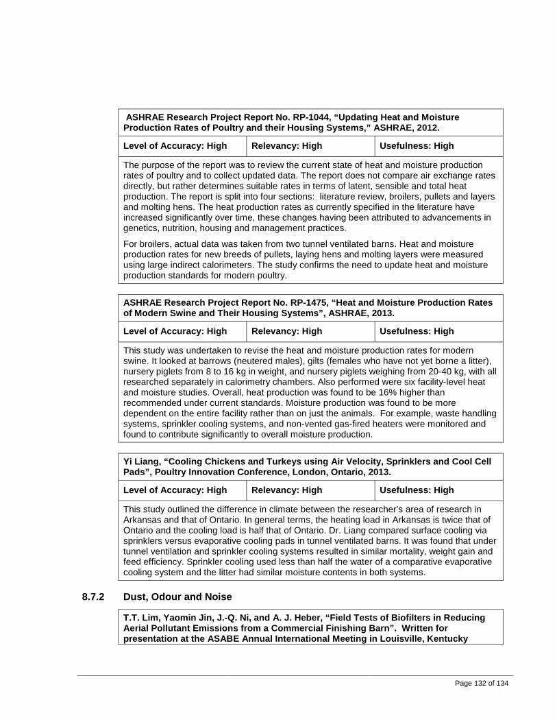
Page 132 of 134
ASHRAE Research Project Report No. RP-1044, “Updating Heat and Moisture Production Rates of Poultry and their Housing Systems,” ASHRAE, 2012.
Level of Accuracy: High Relevancy: High Usefulness: High
The purpose of the report was to review the current state of heat and moisture production rates of poultry and to collect updated data. The report does not compare air exchange rates directly, but rather determines suitable rates in terms of latent, sensible and total heat production. The report is split into four sections: literature review, broilers, pullets and layers and molting hens. The heat production rates as currently specified in the literature have increased significantly over time, these changes having been attributed to advancements in genetics, nutrition, housing and management practices.
For broilers, actual data was taken from two tunnel ventilated barns. Heat and moisture production rates for new breeds of pullets, laying hens and molting layers were measured using large indirect calorimeters. The study confirms the need to update heat and moisture production standards for modern poultry.
ASHRAE Research Project Report No. RP-1475, “Heat and Moisture Production Rates of Modern Swine and Their Housing Systems”, ASHRAE, 2013.
Level of Accuracy: High Relevancy: High Usefulness: High
This study was undertaken to revise the heat and moisture production rates for modern swine. It looked at barrows (neutered males), gilts (females who have not yet borne a litter), nursery piglets from 8 to 16 kg in weight, and nursery piglets weighing from 20-40 kg, with all researched separately in calorimetry chambers. Also performed were six facility-level heat and moisture studies. Overall, heat production was found to be 16% higher than recommended under current standards. Moisture production was found to be more dependent on the entire facility rather than on just the animals. For example, waste handling systems, sprinkler cooling systems, and non-vented gas-fired heaters were monitored and found to contribute significantly to overall moisture production.
Yi Liang, “Cooling Chickens and Turkeys using Air Velocity, Sprinklers and Cool Cell Pads”, Poultry Innovation Conference, London, Ontario, 2013.
Level of Accuracy: High Relevancy: High Usefulness: High
This study outlined the difference in climate between the researcher’s area of research in Arkansas and that of Ontario. In general terms, the heating load in Arkansas is twice that of Ontario and the cooling load is half that of Ontario. Dr. Liang compared surface cooling via sprinklers versus evaporative cooling pads in tunnel ventilated barns. It was found that under tunnel ventilation and sprinkler cooling systems resulted in similar mortality, weight gain and feed efficiency. Sprinkler cooling used less than half the water of a comparative evaporative cooling system and the litter had similar moisture contents in both systems.
8.7.2 Dust, Odour and Noise
T.T. Lim, Yaomin Jin, J.-Q. Ni, and A. J. Heber, “Field Tests of Biofilters in Reducing Aerial Pollutant Emissions from a Commercial Finishing Barn”. Written for presentation at the ASABE Annual International Meeting in Louisville, Kentucky

Page 133 of 134
August 7 – 10, 2011.
Level of Accuracy: High Relevancy: High Usefulness: High
Two commercially available odour cell technologies with elevated-bed wood chip biofilters were tested at a swine finishing farm in Indiana for mitigating aerial pollutant emissions. The biofilters were installed on existing pit ventilation fans, and a third fan was left as a control. It was found that a 254-mm (10-inch) thick biofilter reduced concentrations of NH3 by 18%- 45%, and H2S by 27%- 42%. PM10 (particulate matter up to 10 micrometers in size) particles were reduced by 62% - 96%. The empty bed residence times (EBRTs) were 0.6 seconds for the 254-mm biofilters, and the pressure drop was 57 Pa (0.24 in w.c.). The biofilters were relatively inexpensive and easy to install; they, however, require automated water spray systems to be installed alongside and require weekly inspection and maintenance. Wintertime operation was not discussed.
Lide Chen and Howard Neibling, “CIS No. 1207 Biofilters in Animal Agriculture”, University of Idaho Extension, March 2014.
Level of Accuracy: High Relevancy: High Usefulness: High
This publication provides a high-level overview of biofilter technology, including factors affecting performance, removal efficiency and economics. For cold weather operation, the paper suggests that water sprinkling is not required, as warm air from animals provides enough moisture to the media bed.
Kevin A. Janni, Richard E. Nicolai, Steven J. Hoff, Rose M. Stenglein, “Biofilters for Odor and Air Pollution Mitigation in Animal Agriculture”, Iowa State University, October 2011.
Level of Accuracy: Moderate Relevancy: High Usefulness: High
This paper provides a high-level overview of biofilter technology, similar to the University of Idaho reference above. The publication concludes that heating a biofilter in winter to prevent freezing is typically not cost effective.
Stéphane P. Lemay, Ernest M. Barber, Myles Bantle, Dominic Marcotte,“An Oil Sprinkling System for Dust Control in Pig Buildings”, Prairie Swine Center Annual Research Report, 1999.
Level of Accuracy: High Relevancy: High Usefulness: Moderate
The annual report suggests that the swine industry could see a reduction in indoor dust levels of 50% to 80 % by using oil spraying at a cost less than $1.00 per pig sold. The report provides a brief overview of an automatic system used in a two week trial. Long-term effects of oil sprinkling need further research.
X. Wang, “Odour Concentrations in Natural Ventilated Pig Sheds in Australia”, ASAE, 2003.
Level of Accuracy: High Relevancy: Moderate Usefulness: Low
The study measured odour in six different naturally ventilated pig sheds over the course of

Page 134 of 134
one and a half years. The study found that that there was no significant difference in odour concentrations at three different times of the day (morning, afternoon and evening) inside the same sheds. It was also found that there were no significant differences in average odour concentrations in different months for most of the sheds. For the different types of sheds, however, significant differences in odour concentrations did indeed exist.
Q. Zhang, J. Feddes, I. Edeogu, M. Nyachoti, J. House, D. Small, C. Liu, D. Mann, G. Clark, “Odour Production, Evaluation and Control”. Final report submitted to Manitoba Livestock Manure Management Initiative Inc., 2002.
Level of Accuracy: High Relevancy: Moderate Usefulness: Moderate
The report does not specifically target ventilation; however, it provides a very complete discussion of the main issues associated with odour production for swine. Included are: 1. Odour measurement and odour evaluation technology 2. Odour production and odour release quantification 3. Feed additives and dietary manipulation 4. Manure additives 5. In-barn manure handling 6. Manure storage design and management 7. Biofiltration 8. Dust control, and 9. Emerging technologies in swine odour research. Also included is an appendix with tables listing odour compound detection thresholds, estimation of odour emission rates from typical swine facilities, and comparison of biofilter media types.
8.8 Market Statistics References
1 Fast Stats
2 Production of milk and cream by province, StatsCan
3 Farms, by farm type and province
4 Dairy Factsheet
5 Pork Factsheet
6 Production of poultry, by province
7 Economic impact of BC's dairy, chicken, turkey, hatching egg and table egg industries - 2011 update