aerodynamic analysis and design of a twin engine …
TRANSCRIPT
28TH INTERNATIONAL CONGRESS OF THE AERONAUTICAL SCIENCES
1
Abstract
The present paper deals with the preliminary design of a general aviation Commuter 11 seat aircraft. The Commuter aircraft market is today characterized by very few new models and the majority of aircraft in operation belonging to this category are older than 35 years. Tecnam Aircraft Industries and the Department of Aerospace Engineering (DIAS) of the University of Naples "Federico II" are deeply involved in the design of a new commuter aircraft that should be introduced in this market with very good opportunities of success. This paper aims to provide some guidelines on the conception of a new twin-engine commuter aircraft with eleven passengers. Aircraft configuration and cabin layouts choices are shown, also compared to the main competitors. The research activity also deals with the aerodynamic design that has been performed at DIAS during 2011 and it was focused on a general aerodynamic analysis and a deep investigation on some particular effects (such as the wing-fuselage interference or the nacelle lift contribution and their effect on wing span loading). The aerodynamic analysis was also essential to have an accurate estimation of aircraft stability and control derivatives (both longitudinal and lateral-directional) and to lead to a right sizing of tail surfaces. The aerodynamic analysis have been carried out through the use of a 3-D panel code internally developed and the aerodynamic analysis performed through 3-D panel code calculations have been also supported by semi-empirical estimation methodologies. Design of winglets to improve climb performance will be presented.
1. Introduction
Many in the industry had anticipated 2011 to be the year when the General Aviation manufacturing industry would begin to recover. However, the demand for business airplanes and services, especially in the established markets of Europe and North America, remained soft and customer confidence in making purchase decision in these regions remained weak. This inactivity, nonetheless, was offset in part by demand from the emerging markets of China and Russia. While a full resurgence did not take place in 2011, the year finished with signs of recovery and reason of optimism. GAMA (General Aviation Manufacturer Association) 2011 Statistical Databook & Industry Outlook [1],which is usually a very useful and impressive source of data and statistics for general aviation, reports that the average age of general aviation registered aircraft is 46 year for single-engine piston powered aircraft and 15 years for single-engine turboprop aircraft. The average age for twin-engine 8-12 seats aircraft is 42 years for piston powered models and about 29 years for twin-engine turboprop commuter aircraft. These impressive data dramatically show the need of new aircraft model which will be characterized also by the application of new technologies like composite, light structures, new engines (with lower weight and lower fuel consumption) and new avionics and flight control systems. Since 1990 Tecnam Aircraft Industries (www.tecnam.com) is involved in the design, development and construction of several light and ultra light aircraft with 2 and 4-seat,
AERODYNAMIC ANALYSIS AND DESIGN OF A TWIN ENGINE COMMUTER AIRCRAFT
Fabrizio Nicolosi*, Pierluigi Della Vecchia*, Salvatore Corcione*
*Department of Aerospace Engineering - University of Naples Federico II [email protected]; [email protected], [email protected]
Keywords: Aircraft Design, Commuter Aircraft, Aerodynamic Analysis

FABRIZIO NICOLOSI, PIERLUIGI DELLA VECCHIA, SALVATORE CORCIONE
2
characterized by high-wing and low-wing configurations. The company has acquired good and consolidated experience in design of light aluminum alloy aircraft structures. In the last five years also the composites materials has been deeply used, until to realize some models almost completely in carbon fiber(fuselage and vertical stabilizer). Several research activities have been focused on reducing the empty weight, improving aircraft aerodynamics and flying qualities and reducing aircraft costs. Just for example bringing together an advanced technology all carbon fiber fuselage with a metal wing and stabilator based on the best of Tecnam's recent P2006T Twin and P2008 has been constructed the P2010, shown in Fig. 1.
Fig. 1. P2010 4-seat FAR23 aircraft
Utilizing both carbon fiber and metal has allowed to optimize aerodynamic quality, weight and reliability. Carbon fiber ensures smooth surfaces and allows for an elegance and styling it would expect from Italy. Metal is used for the wing and stabilator to provide further strength and stability. In this paper the design of a new commuter aircraft, named P2012 Traveller, with 11-seats, is presented. The airplane design is under development at Tecnam Aeronautical Industries under the guidance of Prof. L. Pascale, designer of all Tecnam aircraft and known all over the world as one of the main expert in the design of general aviation aircraft. The authors are deeply involved in the definition and optimization of aircraft shape and especially on the correct estimation of aircraft aerodynamics. Since the middle of 90’s the authors have been involved in the design of light aircraft [2]. All the software and the experimental technologies like
wind-tunnel tests have developed at the Department of Aerospace Enginnering of University of Naples have been deeply presented in [3]. During the last 10 years some unusual aircraft have been analysed and designed. In [4] the authors have been designing building and testing a small RPV model characterized by 3 lifting surfaces. In 2005 the design of a STOL ultralight aircraft characterized by application of composite material have been carried out by the authors as can be read in [5]. In previous papers [6] the authors have been collaborating with Tecnam the designer for twin-engine four seats light aircraft (P2006T). In the last years and since 1996 in the Department of Aerospace Engineering the aerodynamic design and optimization of light aircraft components has been carried out. Significant results have been obtained in the design of new high-lift airfoils for STOL ultralight category [7]. The research group has been also deeply involved in flight tests of general aviation aircraft for flight certification and flight performances measurements [8]. Some deeper analysis of flight tests results has been also developed by the authors and presented in [9], where the application of the parameter estimation from flight tests is presented. The present paper shows some general features of the aircraft that are coming from market requirements. The aircraft will be characterized by a very comfortable fuselage cabin to accommodate up to 11 passengers and will be equipped with two piston Lycoming TEO-540-A1A engines rated 350 hp each. This new airliner has been designed to comply with both FAR part 23 and EASA CS-23. The research activity dealing with the aerodynamic design that has been performed at DIAS during 2011 was addressed toward a general aerodynamic analysis and a deep investigation on some particular effects(such as the wing-fuselage interference or the nacelle lift contribution and their effect on wing span loading). The aerodynamic analysis was also essential to have an accurate estimation of aircraft stability and control derivatives(both longitudinal and lateral-directional) and to lead to a correct sizing of tail surfaces. Vertical tail contribution on the

3
AERODYNAMIC ANALYSIS AND DESIGN OF A TWIN ENGINE COMMUTER AIRCRAFT
directional stability has been carefully investigated to better understand the mutual effect with the others aircraft components, wing, fuselage and horizontal tail. The aerodynamic analysis has been performed trough a fast and reliable panel code solver available at DIAS. This software allows the calculation of the nonlinear aerodynamic characteristics of arbitrary configurations in subsonic flow. Potential flow is analyzed with a subsonic panel method; the program is a surface singularity distribution based on Green’s identity. Nonlinear effects of wake shape are treated in an iterative wake relaxation procedure; the effects of viscosity are treated in an iterative loop coupling potential flow and integral boundary layer calculations. The compressibility correction is based on Prandtl-Glauert rule. The aerodynamic analysis has been also supported from by semi-empirical estimation methodologies (like those proposed by Roskam0). Particular care has been also posed to the winglets design. This wing tip device has been designed mainly to improve the climb performance in one engine inoperative conditions, without affect significantly cruise performances.
1.1 Market analysis of commuter aircraft
Commuter aircraft market is today related to old model. The major airlines in this segment have been demanding a replacement for many hundreds of "heritage" airplanes in the FAR23/CS23 category currently in service around the world - as many are now coming to the end of their useful commercial life. Many relevant guidelines in the design of Commuter Aircraft can be found in [11], where the experience of Embraer Company is reported and many important consideration on other general aviation producers during the 90’s are shown. Also in NASA-SP406 [12] some very important technologies to be introduced for commuter aircraft are well described and defined as main design drivers for commercial success and effectiveness of these machines. The main idea behind the introduction of the P2012 Traveller is ensuring that not only passenger demands for comfort and safety are met but that potential
operators of the P2012 Traveller are now able to afford an airplane with significantly improved direct operating costs, more efficient maintenance procedures and appreciation for ensuring that the industry takes into account global environmental considerations such as the need for lower fuel burn and less noise emissions. As it can been seen in Table 1, all the major commuter aircrafts within a segment of 6-15 seats was introduced more than 30 years ago and they are also in use today. It can be clearly noticed that almost all commuter aircraft in operation are characterized by a twin-engine arrangement, being the Cessna Caravan the only single-engine aircraft of this category with a certain commercial success. The data presented in table 1 are important to highlight some guidelines in the estimation of average weight of aircraft belonging to this category and on flight performances. The cruise speed of a Commuter (9-12 seats aircraft) is in average between 180 and 200 kts at an average cruise altitude of about 7000-10000 ft. The P2012, as design specifications, is characterized by a cruise speed of 215 kts at 10000 ft altitude. One of the main features for commuter aircraft is the take-off field length and the capability to operate on very short runways. The P2012 has been designed to have a very small minimum control speed and this leads to a take-off distance of about 640 m. From table 1 some interesting data can be extracted concerning in example the statistical law that links the empty weight versus maximum take-off weight. The P2012 preliminary weight estimation gives for this aircraft a emptyweight vs MTOW ratio that lies exactly in the average value (about 0.60).

4
AERODYNAMIC ANALYSIS AND DESIGN OF A TWIN ENGINE COMMUTER AIRCRAFT
Model Specifications
CESSNA 402
CESSNA CARAVAN
PIPER NAVAJOS
BRITTEN NORMAN B2N
BEECHCRAFT Baron
BEECHCRAFT Duke
PARTENAVIA P68
TECNAM P2012
Year 1966 1982 1967 1965 1969 1968 1970 2012 Wingspan m 13.45 15.87 12.4 14.94 11.53 11.97 12 14 Wing area sqm 21.00 25.96 21.30 30.20 18.50 19.78 18.60 25.00 Aspect ratio AR 8.61 9.70 7.22 7.39 7.19 7.24 7.74 7.84 Lenght m 11.09 11.46 9.94 10.86 9.09 10.31 9.55 11.70
Height m 3.49 4.53 3.96 4.18 2.97 3.76 3.40 4.10 Cabin height m 1.27 1.30 1.17 1.30 1.27 n.a. 1.20 1.37 Cabin width m 1.42 1.57 0.76 1.10 1.07 n.a. 1.04 1.50 Cabin lenght m 4.98 5.28 4.42 4.60 3.84 n.a. 4.05 4.32
Landing gear type tricycle ‐
retractable tricycle‐fixed
tricycle ‐retractable
tricycle‐fixed tricycle ‐
retractable tricycle ‐
retractable tricycle ‐retr. or
fixed tricycle‐fixed
Engine Manufacter Continental Pratt‐Wittney Lycoming Lycoming Continental Lycoming Lycoming Lycoming Model TSIO‐520‐VB PT 6A‐114A TIO‐540‐A I0‐540 IO‐550‐C TIO‐541‐E1C4 IO‐360‐A1B6 TEO‐540‐A1A
Horsepower hp 2*325 1*675 2*310 2*300 2*300 2*380 2*200 2*350 Propeller
Manufacter ‐ Type McCauley 3
blade McCauley 3
blade McCauley 3
blade Hartzell 2/3
blade Hartzell 3‐blade Hartzell 3‐blade
Hartzell 2‐blade
Hartzell or MT 3‐blade
Diameter m 2.25 2.69 2.03 1.98 1.93 1.83 Design Weight
Max. gross weight kg 3107 3629 2948 2994 2495 3073 1990 3290 Std. Empty weight kg 1845 1832 1990 1667 1901 1990 1230 2110 Useful load kg 1262 1722 958 1128 682 n.a. 680 Seating capacity 9 8 to 13 7 9 5 5 6 9 Fuel capacity liters 780 1257 708 492 528 1223 Wing loading lb/sqft 30.30 28.63 28.35 20.31 27.62 31.82 21.91 26.95 Power loading lb/hp 10.54 11.85 10.48 11.00 9.17 8.91 10.97 10.36
Performance
Max. speed VNE kts 230 186 @FL100 226 183 IAS 223 230 193 244 Cruise Speed kts 213 175 IAS 201 139 @FL70 202 199 165 @FL75 215 @FL10 Min. contr. speed VMC
kts 80.0 IAS n.a. 74.0 IAS n.a. n.a. 80.0 IAS n.a 73.0 IAS
Stall speed, flaps up
kts 80.0 IAS 75 CAS 69.7 IAS 50.0 IAS 84.0 IAS 71.0 IAS 68 IAS 78.0 IAS
Stall speed, flaps down
kts 71.0 IAS 61 CAS 63.2 IAS 40.0 IAS 73.0 IAS 62.5 IAS 57.0 IAS 62.3 IAS
Best rate of climb ft/min 1450 1234 1395 860 1670 1601 1240 1600 Range max nmi 1273 1295 @FL200 1011 503 1559 1227 1598 @FL70 662
Take off distance m 670 626 695 371 701 632 400 640 Landing distance m 757 505 554 299 762 402 600 549
Table 1. Aircraft comparison
Fig. 2. Empty weight vs maximum takeoff weight of several commuter aircrafts
CESSNA 402 CESSNA CARAVAN 208PIPER NAVAJOS
PIPER AEROSTAR
BRITTEN NORMAN 2B
BEECHCRAFT BARON
P68
P2012
CESSNA 310
CESSNA 340
BEECHCRAFT DUKECESSNA 414
ADAMS A500
CESSNA T303
BEAGLE 206
BEECHCRAFT QUEEN AIR
1000
1200
1400
1600
1800
2000
2200
2400
2600
2800
1000 1500 2000 2500 3000 3500 4000 4500
WE(kg)
WTO (kg)
.

5
AERODYNAMIC ANALYSIS AND DESIGN OF A TWIN ENGINE COMMUTER AIRCRAFT
1.2 Sizing and configurations
The sizing of the P2012 has been accomplished through the use of classical methodologies and approach, like these ones suggested by Roskam [10]. In the present paragraph all results about the performed study and development of the configuration will be presented. The design of the aircraft has been accomplished starting from the following design specifications: a) Easy cabin access and cabin comfort b) Spacious luggage compartment, c) Reduced take-off run (<1900 ft) and take-off
from not prepared runways d) Cruise flight speed of about 200 Kts at flight
altitude of 10000 ft e) Range higher than 600 nm The easy cabin access and a better aircraft clearance has leaded to the necessity of high-wing configuration. Other considerations that has to be taken carefully into account are aircraft CG position and certification problem arising from propeller longitudinal position. In fact both FAR 23 and CS23 state that two lines at ± 5° from propeller disk do not have to intersect pilot position or pilot flight command. This leads to the fact that the two propellers have to be located well behind or well in front of pilot position From the consideration to guarantee possible take-off from not prepared and grass runways the low-wing configuration is penalized due to possible ingestion for the engine and high possibility for the propeller to not work in optimal conditions. Also considerations of easy-access on board leads to a high-wing configuration as was done for P2006T, see [6].
The application of restrictions on power loading and wing loading coming from the take-off, landing and cruise performances defined in the design requirements and all necessary climb characteristics for FAR23 certifications rules leads to the graph represented in fig. 3, which show the available area in which the design point for the aircraft can be chosen. The P2012 power loading (about 10 lb/hp), that is similar to
other aircraft (also presented in table 1) leads to even higher cruise performances (about 210 kts) than those considered in the design requirements. In the calculations of restrictions, concerning take-off run (1800 ft) and landing run (2000 ft) limitations, a maximum lift coefficient of about 1.9(take-off) and 2.2 (landing) have been considered as reliable and achievable values with a single-slotted flap high-lift system. For climb and cruise limitations, a parasite drag coefficient of 280 drag counts has been considered. An Oswald factor of about 0.80-0.83 (achievable through the use of winglets, see also [8]) has been considered.
Fig. 3. Power loading and wing loading of several commuter aircraft
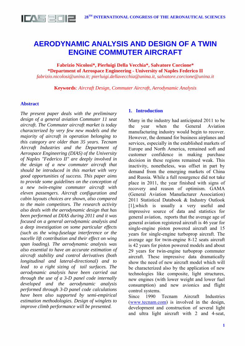
In fig. 4 the fuselage design and the cabin arrangements are presented. Easy cabin access and high level of cabin comfort leads to an internal design well described in fig. 4. Figure 5 presents some possible internal cabin arrangements which will help the commercial success of the aircraft through easy re-configuration for different possible applications. A spacious luggage compartment has been considered by Tecnam and placed in the rear part of the cabin (see also fig. 4). The final 3-view of the aircraft as designed by Tecnam is shown in fig. 6.
P2012CESSNA 402
CESSNA CARAVAN
CESSNA 414
PIPER NAVAJOS
BRITTEN NORMAN
BEECH DUKE
P68
6
8
10
12
14
16
18
20
15 20 25 30 35
W/P(lb/hp)
W/S (lb/sqft)
TAKE OFF
LANDING
CLIMB FAR23.65 a
CLIMB FAR23.65 b
CLIMB FAR23.67
CLIMB FAR23.77
CRUISE
FABRIZIO NICOLOSI, PIERLUIGI DELLA VECCHIA, SALVATORE CORCIONE
6
Fig. 4. P2012 Cabin arrangement and internal design (courtesy of Tecnam)
Fig. 5. P2012 Cabin arrangement for all possible versions (courtesy of Tecnam)
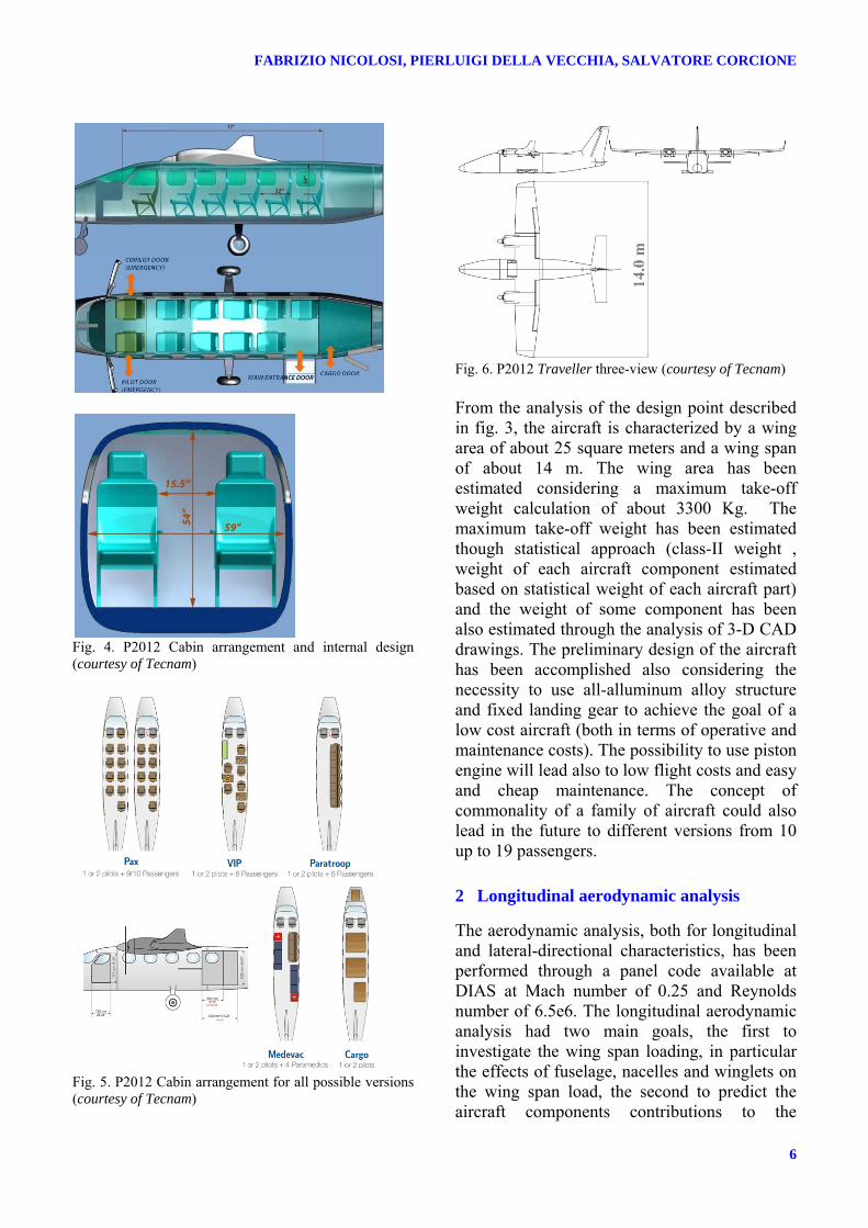
Fig. 6. P2012 Traveller three-view (courtesy of Tecnam) From the analysis of the design point described in fig. 3, the aircraft is characterized by a wing area of about 25 square meters and a wing span of about 14 m. The wing area has been estimated considering a maximum take-off weight calculation of about 3300 Kg. The maximum take-off weight has been estimated though statistical approach (class-II weight , weight of each aircraft component estimated based on statistical weight of each aircraft part) and the weight of some component has been also estimated through the analysis of 3-D CAD drawings. The preliminary design of the aircraft has been accomplished also considering the necessity to use all-alluminum alloy structure and fixed landing gear to achieve the goal of a low cost aircraft (both in terms of operative and maintenance costs). The possibility to use piston engine will lead also to low flight costs and easy and cheap maintenance. The concept of commonality of a family of aircraft could also lead in the future to different versions from 10 up to 19 passengers.
2 Longitudinal aerodynamic analysis
The aerodynamic analysis, both for longitudinal and lateral-directional characteristics, has been performed through a panel code available at DIAS at Mach number of 0.25 and Reynolds number of 6.5e6. The longitudinal aerodynamic analysis had two main goals, the first to investigate the wing span loading, in particular the effects of fuselage, nacelles and winglets on the wing span load, the second to predict the aircraft components contributions to the

7
AERODYNAMIC ANALYSIS AND DESIGN OF A TWIN ENGINE COMMUTER AIRCRAFT
longitudinal stability and control. It is to notice that the first item is a crucial aspect to right design the wing structure and the results are used for certification flight load assessment.
2.1 Wing aerodynamic analysis and loads
The effect of fuselage, nacelles and winglets on the wing span loading has been deeply investigated by the authors in a previous work, also to validate the numerical panel code [6]. Several aerodynamic analysis has been performed on wing configuration(with winglets), wing-body configuration and wing-body-nacelles configurations at M=0.25 and Re=6.5e6.
Fig. 7. Wing geometry details: winglets, nacelles and fuselage junction The main goal of the investigation was to investigate fuselage effect on wing lift close to wing-fuselage junction and to have more information about lift loss due to nacelles in terms of localization of lift loss and effects along wing span. Wing configuration of the aircraft is shown in Fig. 7. A classical double-tapered wing planform has been chosen to limit wing weight, to have very low induced drag and to simplify the construction of the inboard wing and inboard flap (rectangular). In Fig. 8 and Fig. 9 the wing span lift coefficient and the wing span loading of the wing, wing-body and wing-body-nacelles configurations are respectively depicted at different angles of attack. It is easy to see that the nacelle causes a lift loss in the wing zone where it is installed, but it has a positive effect on the wing-body interference. The Figure 10 shows the pressure coefficient distribution on the wing-body with nacelle at an angle of attack of 0 deg. As matter of fact, the nacelle geometry creates a flow acceleration in the wing zone between the
nacelle itself and the fuselage, so to give a slightly higher lift coefficient especially at higher angle of attack in this wing area(see Fig. 10). Thanks to the fact that the nacelle geometry has an higher local chord, the wing span loading has an almost regular span-wise variation as shown in Fig. 9.
Fig. 8. Wing span lift coefficient comparison of wing, wing-body and wing-body-nacelle configurations
Fig. 9. Wing span loading comparison of wing, wing-body and wing-body-nacelle configurations
The lift in the nacelle area does not take into account the flow separation on the lower surface
0.0
0.2
0.4
0.6
0.8
1.0
1.2
1.4
0.0 0.2 0.4 0.6 0.8 1.0
Cl
η
WingWingBodyWingBodyNac.
0.0
0.5
1.0
1.5
2.0
2.5
0.0 0.2 0.4 0.6 0.8 1.0
c*Cl
η
WingWingBodyWingBodyNac.
α = 0deg
α = 4deg
α = 8deg
α = 0deg
α = 4deg
α = 8deg

FABRIZIO NICOLOSI, PIERLUIGI DELLA VECCHIA, SALVATORE CORCIONE
8
of nacelle. Numerical calculations have been performed on a closed and streamlined nacelle shape and the propeller effect is not considered. Winglets span-wise effect has been carefully investigated during the winglets design, controlling winglets toe and cant angle. The results in Fig. 8 and Fig. 9, show a very regular wing span loading in the winglets zone, in such manner to avoid any separation flow at higher angle of attack and sideslip.
Fig. 10. Pressure coefficient distribution over the wing-body-nacelles configuration, α=0deg
2.2 Stability and control
The P2012 Traveller longitudinal stability and control has been checked through an aerodynamic analysis that has been carefully performed through a panel code software [3] and it has been also checked with semi-empirical formulations[13, 14]. The longitudinal aerodynamic analysis has given the possibility to better predict the aircraft stability behavior, in terms of fuselage instability prediction and horizontal tail plane sizing and position. To predict the fuselage instability, the wing-body-nacelles configuration shown in Fig. has been investigated. In Fig. 11 the pitching moment coefficients of the aircraft components are shown calculated respect to a center o gravity position at x=0.25% and z=0.2% of the mean aerodynamic chord. The black dashed line shows the longitudinal stability curve of the complete aircraft. The fuselage instability (red curve) leads to an aerodynamic center forward
shift of about 13% of the mean aerodynamic chord. Also the nacelles contribution has been isolated and it is even instable due to the forward portion of the nacelles geometry respect to the center of gravity. The fuselage instability estimated by panel methods does not differ by a large amount from the value estimated through semi-empirical methodologies, as it can be observed from the results shown in Table 2. It is interesting to notice the wing pendular stability, due to low CG position respect to the wing, clearly shown in Fig. 11 (blue curve) with higher slope (higher static margin) at higher lift coefficients.
Fig. 11. Comparison of pitching moment coefficients in the complete aircraft configuration
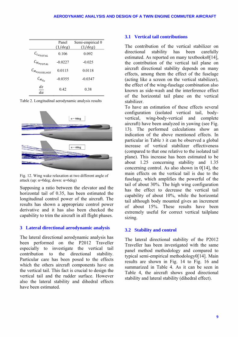
Another important result obtained from the panel code analysis has been a more accurate estimation of the wing wake position on the horizontal tail location. The wing wake relaxation at two different angle of attack is shown in Fig. 12. It is evident that the wing wake is always plentifully above the horizontal tail, moving away from it when the angle of attack increases. From the ratio between the lift slope of the horizontal tail in the body-horizontal configuration and the lift slope of in the wing-body-horizontal configuration has been also estimated the downwash effect, compared in Table 2 with the semi-empirical approach.
‐0.25
‐0.20
‐0.15
‐0.10
‐0.05
0.00
0.05
0.10
0.15
‐2 ‐1 0 1 2 3 4 5 6α (deg)
CM
WingFuselageNacellesHorizontalComplete Aircraft
9
AERODYNAMIC ANALYSIS AND DESIGN OF A TWIN ENGINE COMMUTER AIRCRAFT
Panel
1/ Semi-empirical 0
1/ 0.106 0.092
-0.0227 -0.025
0.0115 0.0118
-0.0355 -0.0347
0.42 0.38
Table 2. Longitudinal aerodynamic analysis results
Fig. 12. Wing wake relaxation at two different angle of attack (up: α=0deg; down: α=6deg)
Supposing a ratio between the elevator and the horizontal tail of 0.35, has been estimated the longitudinal control power of the aircraft. The results has shown a appropriate control power derivative and it has also been checked the capability to trim the aircraft in all flight phases.
3 Lateral directional aerodynamic analysis
The lateral directional aerodynamic analysis has been performed on the P2012 Traveller especially to investigate the vertical tail contribution to the directional stability. Particular care has been posed to the effects which the others aircraft components have on the vertical tail. This fact is crucial to design the vertical tail and the rudder surface. However also the lateral stability and dihedral effects have been estimated.
3.1 Vertical tail contributions
The contribution of the vertical stabilizer on directional stability has been carefully estimated. As reported on many textbooks0[14], the contribution of the vertical tail plane on aircraft directional stability depends on many effects, among them the effect of the fuselage (acting like a screen on the vertical stabilizer), the effect of the wing-fuselage combination also known as side-wash and the interference effect of the horizontal tail plane on the vertical stabilizer. To have an estimation of these effects several configuration (isolated vertical tail, body-vertical, wing-body-vertical and complete aircraft) have been analyzed in yawing (see Fig. 13). The performed calculations show an indication of the above mentioned effects. In particular in Table 3 it can be observed a global increase of vertical stabilizer effectiveness (compared to that one relative to the isolated tail plane). This increase has been estimated to be about 1.25 concerning stability and 1.35 concerning control. As also shown in 0[14], the main effects on the vertical tail is due to the fuselage, which amplifies the powerful of the tail of about 30%. The high wing configuration has the effect to decrease the vertical tail capability of about 10%, while the horizontal tail although body mounted gives an increment of about 15%. These results have been extremely useful for correct vertical tailplane sizing.
3.2 Stability and control
The lateral directional stability of the P2012 Traveller has been investigated with the same panel method methodology and compared to typical semi-empirical methodology0[14]. Main results are shown in Fig. 14 to Fig. 16 and summarized in Table 4. As it can be seen in Table 4, the aircraft shows good directional stability and lateral stability (dihedral effect).
10
AERODYNAMIC ANALYSIS AND DESIGN OF A TWIN ENGINE COMMUTER AIRCRAFT
Configuration_
(1/deg)
(1/deg) _
(1/deg) (1/deg)
RATIO
_ RATIO RATIO
_ RATIO
V ‐0.00583 0.00470 ‐0.00235 0.00201 1.000 1.000 1.000 1.000 BV ‐0.00735 0.00551 ‐0.00291 0.00230 1.261 1.172 1.238 1.144 WBV ‐0.00515 0.00541 ‐0.00206 0.00226 0.883 1.151 0.877 1.124 BVH ‐0.00842 0.00623 ‐0.00335 0.00259 1.444 1.326 1.426 1.289
Complete ‐0.00728 0.00634 ‐0.00294 0.00263 1.249 1.349 1.251 1.308
Table 3. Estimation of vertical tail stabilizer and rudder effectiveness in stability and control (panel method)
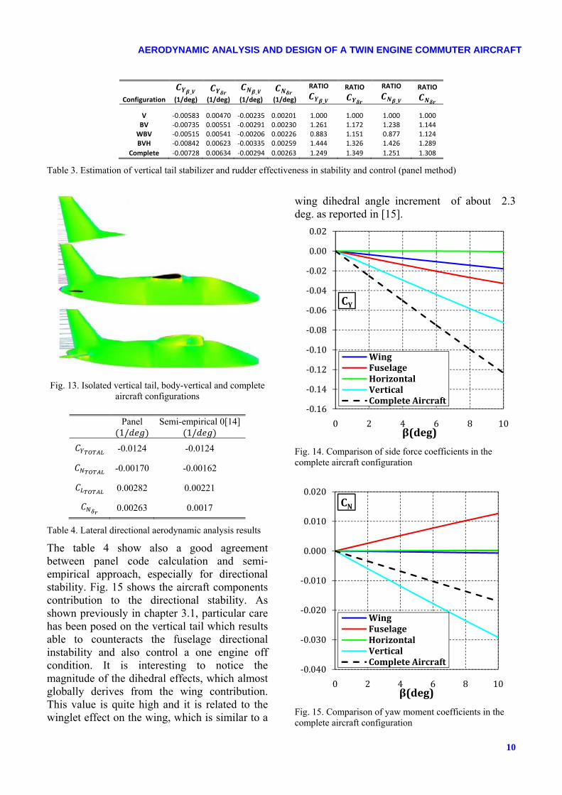
Fig. 13. Isolated vertical tail, body-vertical and complete aircraft configurations
Panel
1/ Semi-empirical 0[14]
1/ -0.0124 -0.0124
-0.00170 -0.00162
0.00282 0.00221
0.00263 0.0017
Table 4. Lateral directional aerodynamic analysis results
The table 4 show also a good agreement between panel code calculation and semi-empirical approach, especially for directional stability. Fig. 15 shows the aircraft components contribution to the directional stability. As shown previously in chapter 3.1, particular care has been posed on the vertical tail which results able to counteracts the fuselage directional instability and also control a one engine off condition. It is interesting to notice the magnitude of the dihedral effects, which almost globally derives from the wing contribution. This value is quite high and it is related to the winglet effect on the wing, which is similar to a
wing dihedral angle increment of about 2.3 deg. as reported in [15].
Fig. 14. Comparison of side force coefficients in the complete aircraft configuration
Fig. 15. Comparison of yaw moment coefficients in the complete aircraft configuration
‐0.16
‐0.14
‐0.12
‐0.10
‐0.08
‐0.06
‐0.04
‐0.02
0.00
0.02
0 2 4 6 8 10
CY
β(deg)
WingFuselageHorizontalVerticalComplete Aircraft
‐0.040
‐0.030
‐0.020
‐0.010
0.000
0.010
0.020
0 2 4 6 8 10
CN
β(deg)
WingFuselageHorizontalVerticalComplete Aircraft
11
AERODYNAMIC ANALYSIS AND DESIGN OF A TWIN ENGINE COMMUTER AIRCRAFT
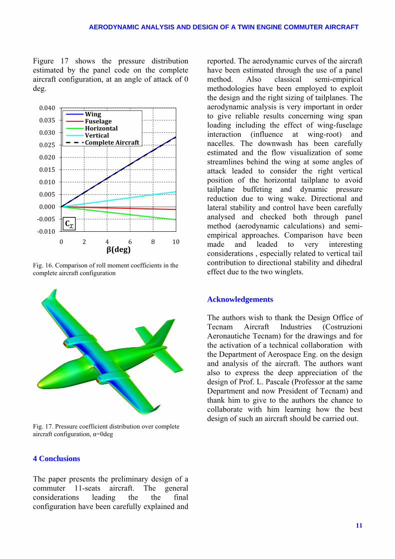
Figure 17 shows the pressure distribution estimated by the panel code on the complete aircraft configuration, at an angle of attack of 0 deg.
Fig. 16. Comparison of roll moment coefficients in the complete aircraft configuration
Fig. 17. Pressure coefficient distribution over complete aircraft configuration, α=0deg
4 Conclusions
The paper presents the preliminary design of a commuter 11-seats aircraft. The general considerations leading the the final configuration have been carefully explained and
reported. The aerodynamic curves of the aircraft have been estimated through the use of a panel method. Also classical semi-empirical methodologies have been employed to exploit the design and the right sizing of tailplanes. The aerodynamic analysis is very important in order to give reliable results concerning wing span loading including the effect of wing-fuselage interaction (influence at wing-root) and nacelles. The downwash has been carefully estimated and the flow visualization of some streamlines behind the wing at some angles of attack leaded to consider the right vertical position of the horizontal tailplane to avoid tailplane buffeting and dynamic pressure reduction due to wing wake. Directional and lateral stability and control have been carefully analysed and checked both through panel method (aerodynamic calculations) and semi-empirical approaches. Comparison have been made and leaded to very interesting considerations , especially related to vertical tail contribution to directional stability and dihedral effect due to the two winglets. Acknowledgements The authors wish to thank the Design Office of Tecnam Aircraft Industries (Costruzioni Aeronautiche Tecnam) for the drawings and for the activation of a technical collaboration with the Department of Aerospace Eng. on the design and analysis of the aircraft. The authors want also to express the deep appreciation of the design of Prof. L. Pascale (Professor at the same Department and now President of Tecnam) and thank him to give to the authors the chance to collaborate with him learning how the best design of such an aircraft should be carried out.
‐0.010
‐0.005
0.000
0.005
0.010
0.015
0.020
0.025
0.030
0.035
0.040
0 2 4 6 8 10
CL
β(deg)
WingFuselageHorizontalVerticalComplete Aircraft

FABRIZIO NICOLOSI, PIERLUIGI DELLA VECCHIA, SALVATORE CORCIONE
12
References
[1] GAMA (General Aviation Manufacturer Association) General Aviation Statistical Databook & Industry Outlook 2011.
[2] Giordano V., Coiro D.P., Nicolosi F.”Reconnaissance Very Light Aircraft Design. Wind-Tunnel and Numerical Investigation,” Engineering Mechanics, 2000 vol. 7, No. 2, p. 93-107. ISSN 1210-2717
[3] Coiro D.P., Nicolosi F.“Aircraft Design through Numerical and Experimental Techniques Developed at DPA,” Aircraft Design Journal, vol. 4 – No. 1 , March, 2001. ISSN 1369-8869
[4] Coiro D.P, Nicolosi F., “Design of a Three Surfaces R/C Aircraft Model,”Acta Polytecnica, Vol. 42 no. 1/2002 pp. 44-52. ISSN 1210-2709
[5] Coiro D.P., Nicolosi F., De Marco A., Genito N. and Figliolia S.,“Design of a Low Cost Easy-to-Fly STOL Ultralight Aircraft In Composite Material,”Acta Polytecnica, Vol. 45 no. 4/2005, pp. 73-80 ; ISSN 1210-2709
[6] Pascale, L. and Nicolosi, F., "Design and aerodynamic analysis of a twin engine propeller aircraft", 26th ICAS conference, Anchorage (Alaska, US), 14-19 September, 2008.
[7] Coiro D.P., Nicolosi F., Grasso F., “Design and Testing of Multi-Element Airfoil for Short-Takeoff-and-Landing Ultralight Aircraft,” Journal of Aircraft, Vol. 46, N. 5, September-October 2009, pp. 1795-1807. ISSN 0021-8669, doi: 10.2514/1.43429
[8] Nicolosi F., De Marco A., Della Vecchia P., "Flight Tests, Performances, and Flight Certification of a Twin-Engine Light Aircraft.", AIAA Journal of Aircraft, Vol. 48, No.1, Jan.–Febr. 2011, pp. 177-192, ISSN 0021-8669, doi: 10.2514/1.C031056
[9] Nicolosi F., De Marco A., Della Vecchia P., "Stability, Flying Qualities and Parameter Estimation of a Twin-Engine CS-23/FAR 23 Certified Light Aircraft." AIAA Paper AIAA-2010-7947, AIAA Aircraft Flight Mechanics Conference 2-5 August 2010, Toronto, Canada.
[10] Roskam, J., “Airplane Design, Part VI: Preliminary Calculation of Aerodynamic, Thrust and Power Characteristics,” 2nd ed., DARcoporation Lawrence Kansas, 2000, Chap 4.
[11] Frlschtak C.R., “Learning, Technical Progress and Competitiveness in the Commuter Aircraft Industry: An Analysis of Embrarer,” The World Bank, June 1992
[12] Williams J.P, “Small Transport Aircraft Technology,” NASA SP-460, 1983
[13] Gilruth, R., R. and White, M., D., "Analysis and prediction of longitudinal stability of airplanes", NACA-TR-711, 1941.
[14] ESDU 82010, "Contribution of Fin to Sideforce, Yawing Moment and Rolling Moment Derivatives Due to Sideslip,(Y Sub V) Sub F,(N Sub V) Sub F,(L
Sub V) Sub F,in the Presence of Body,Wing and Tailplane. 82010, ISBN-13: 978-0856793882.
[15] Nickel, K. and Wohlfahrt, M., "Tailless Aircraft in Theory and Practice", American Institute of Aeronautics and Astronautics, Washington D.C., 1994.
Copyright Statement
The authors confirm that they, and/or their company or organization, hold copyright on all of the original material included in this paper. The authors also confirm that they have obtained permission, from the copyright holder of any third party material included in this paper, to publish it as part of their paper. The authors confirm that they give permission, or have obtained permission from the copyright holder of this paper, for the publication and distribution of this paper as part of the ICAS2012 proceedings or as individual off-prints from the proceedings.