design and aerodynamic analysis of a light twin …
TRANSCRIPT

26TH INTERNATIONAL CONGRESS OF THE AERONAUTICAL SCIENCES
1
Abstract
Design of a new twin propeller aircraft named P2006 T has been carried out at Tecnam aircraft industries during 2006. The new design, performed by Prof. L. Pascale, is based on the idea to built a 4-seat aircraft with two light engines (Rotax 912S, usually used for ultralight aircraft) and to enter the market with a twin-engine aircraft with the same weight of a single engine aircraft. The present paper shows all main criteria on which the design of the aircraft and the choice of the configuration have been based. At Dipartimento di Ingegneria Aerospaziale (DIAS) of University of Napoli “Federico II” a deep aircraft aerodynamic investigation has been performed both numerically and experimentally through an extensive wind-tunnel test campaign. All tests and research activities have been focused on the analysis and optimization of aircraft aerodynamics. Detailed measurements of fuselage and nacelle aerodynamic effects will be presented. Design and tests of winglets to improve rate of climb in OEI (One Engine Inoperative) condition will be presented.
1 Introduction During the last 15 years Tecnam Aircraft Industries has been deeply involved in the design, development and construction of more than 10 light and Ultralight(ULM) 2-seat aircraft characterized by high-wing or low-wing configurations. The company has acquired good and consolidated experience in design of light alluminum alloy aircraft structures also introducing interesting technological innovation (for this class of aircraft) like the retractable
gear. All research activities have been focused on reducing the empty weight, improving aircraft aerodynamics and flying qualities and reducing aircraft costs. The market of light aircraft has been growing in the last decade all over the world and Tecnam has reached a leadership with more than 2000 aircraft sold in 15 years. The Department of Aerospace Engineering (DIAS) of University of Naples have been deeply involved in research activities concerning almost all of these aircraft[1,2]. Extensive activities have been carried out in collaboration with Tecnam on structural analysis, structural tests, aerodynamic analysis and optimisation, noise and vibration tests, wind-tunnel tests and flight tests. Almost all light aircraft produced by Tecnam have been tested in the main wind-tunnel belonging to DIAS. An example of light aircraft that have been an important commercial success is shown in fig. 1.
Fig. 1. P92J light aircraft
Since 2006 Tecnam has started his intention to enter the market with a new CS 23 certified 4 seat aircraft. In the last years, starting from the United States, the General Aviation has been
DESIGN AND AERODYNAMIC ANALYSIS OF A LIGHT TWIN-ENGINE PROPELLER AIRCRAFT
L. Pascale*, F. Nicolosi**
*Tecnam Aircraft Industries, Casoria (Naples), ITALY **Dep. Of Aerospace Eng. (DIAS), University of Naples “Federico II” , Naples, ITALY
Keywords: Aircraft Design, Light Twin-engine, Aerodynamic Analysis, Wind-Tunnel Tests

L. PASCALE, F. NICOLOSI
2
revitalized, due to the necessity to decongest the classical skyway system and to use thousands of small airport in the country. With this aim the AGATE consortium was founded in 1994 to develop affordable new technologies to be applied on next generation light airplanes. In addition the fast economical growth of developing countries (like in Africa, south-America and in south-east of Asia) that do not have developed transportation systems has pushed the use and the diffusion of light aircraft in those areas. In example in some remote area of south Africa the transport through light aircraft can be the only solution, taking into account the absence of asphalt roads and the low acquisition and maintenance costs of these kind of machines. General aviation and light aircraft can be also extensively used for flight school, tourist transport and to perform services like aerial monitoring (police patrol or fire monitoring) with a reasonable cost respect to the classical use of helicopter. The other aspect (in particular looking at the not-developed countries market) that has been carefully considered by Tecnam has been the installation of engines using standard automotive fuel instead of aviation fuel. The reason is based on the lower cost and especially on the easy possibility of finding this fuel everywhere. The above remarks put clearly in evidence the growing market for light aircraft with 4 seats, with a flight speed around 250-300 Km/h, with capability of flight altitude up to 12000 ft, with relatively simple , light and not-expensive construction (typical of ultralight and VLA certified aircraft) and so with a reasonable cost and with low maintenance costs. It is very important (considering the possibility of use in not developed areas and the take-off and landing capabilities from not-prepared airfields) the characteristic of relatively short take-off and landing run.
2 Market Analysis and P2006 Design Aspects Design of a new twin propeller aircraft named P2006 VELT (Very Light Twin) has been carried out at Tecnam aircraft industries during 2006. The design of the new aircraft, performed
by Prof. L. Pascale, is based on the idea to built a 4-seat aircraft with two light engines (Rotax 912, usually used for ultralight aircraft) and to enter the market with a twin-engine aircraft with the weight of a single engine one. This project starts with the consideration that Rotax 912 S is the only engine available for the aviation market that uses automotive fuel and is FAR 33 certificated. This engine has been recently designed taking all the advantages of the latest technologies developed in the automotive market over the standard G.A. engines, like reduced frontal area and better weight to power ratio, lower specific fuel consumption, lower propeller rpm i.e. higher efficiency and lower acoustic emissions, stable engine head temperatures due to liquid cooling. So far this modern powerplant, given its moderately low power (73 KW or 100 hp), has been used essentially on two seats single-engine light airplanes. It now becomes evident the opportunity to design a four-seats airplane powered by two of these Rotax engines with a neglecting weight difference, higher safety due to the twin engine arrangement and quite lower costs respect the single engine competitors. In table 1 of the following page we compare the performance and characteristics of some four seat, 200 hp aircraft available on the market today. It is evident that for the first time ever it is possible to compare a twin-engine four seat aircraft with single-engine four-seat aircraft, due to their similar weight and power specifications. The P2006 empty weight is the lowest among twin engine aircrafts while the payload is higher. This can be attributed to the high structural and system efficiency and because of the excellent weight-to-power ratio of the Rotax engine. The wing-mounted engines relieve the aerodynamic load on the wing with a consequently lighter structure. The remarkable expected propulsive efficiency of P2006 can be ascribed to the low propeller rpm and low engine nacelle drag. These aspects, together with a streamlined fuselage, result in a good aerodynamic efficiency, as also confirmed through wind-tunnel tests (see after). From an operating point of view, is worth to consider that the option to use automotive fuel instead of AVGAS allows P2006 operators to
3
DESIGN AND AERODYNAMIC ANALYSIS OF A LIGHT TWIN-ENGINE PROPELLER AIRCRAFT
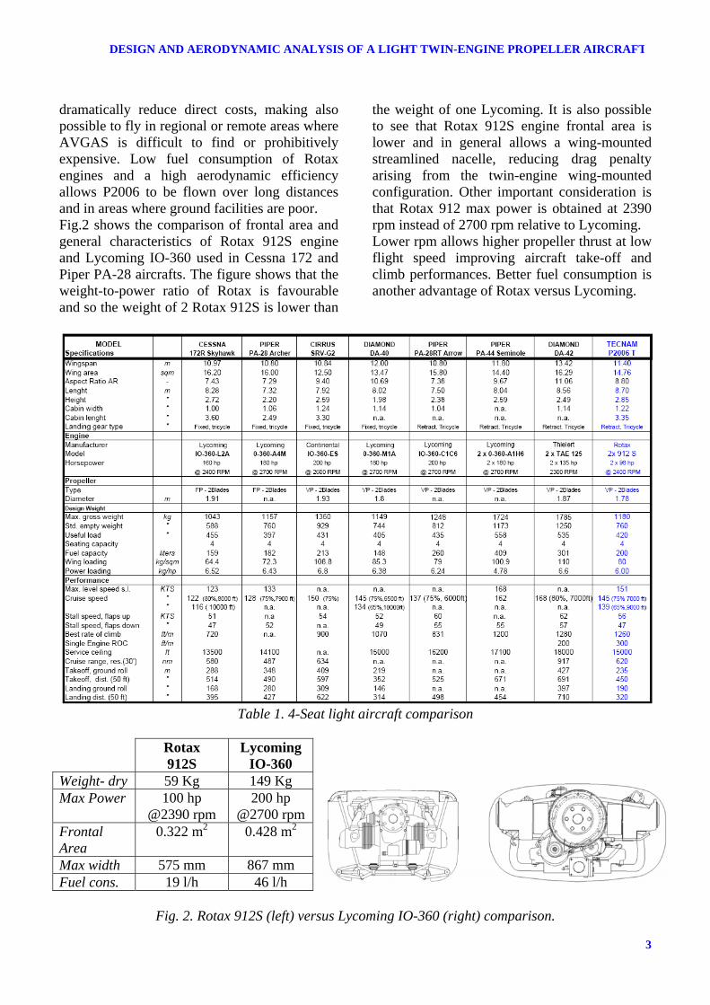
dramatically reduce direct costs, making also possible to fly in regional or remote areas where AVGAS is difficult to find or prohibitively expensive. Low fuel consumption of Rotax engines and a high aerodynamic efficiency allows P2006 to be flown over long distances and in areas where ground facilities are poor. Fig.2 shows the comparison of frontal area and general characteristics of Rotax 912S engine and Lycoming IO-360 used in Cessna 172 and Piper PA-28 aircrafts. The figure shows that the weight-to-power ratio of Rotax is favourable and so the weight of 2 Rotax 912S is lower than
the weight of one Lycoming. It is also possible to see that Rotax 912S engine frontal area is lower and in general allows a wing-mounted streamlined nacelle, reducing drag penalty arising from the twin-engine wing-mounted configuration. Other important consideration is that Rotax 912 max power is obtained at 2390 rpm instead of 2700 rpm relative to Lycoming. Lower rpm allows higher propeller thrust at low flight speed improving aircraft take-off and climb performances. Better fuel consumption is another advantage of Rotax versus Lycoming.
Table 1. 4-Seat light aircraft comparison
Rotax
912S Lycoming
IO-360 Weight- dry 59 Kg 149 Kg Max Power 100 hp
@2390 rpm 200 hp
@2700 rpm Frontal Area
0.322 m2 0.428 m2
Max width 575 mm 867 mm Fuel cons. 19 l/h 46 l/h
Fig. 2. Rotax 912S (left) versus Lycoming IO-360 (right) comparison.

L. PASCALE, F. NICOLOSI
4
The Rotax 912S will drive on P2006 aircraft a 2-blade Hoffmann constant speed propeller with pitch feathering device and with diameter of 1.78 m. The reduced frontal area of Rotax 912S engine, allows to have a good ratio between the area of propeller disk and the engine-nacelle frontal area behind the disk. As we know the engine frontal area behind the propeller can reduce propeller efficiency and this reduction is associated with the above mentioned ratio. The propulsive maximum thrust available by two Rotax 912S has been evaluated through Hoffmann propeller charts. Corrections to take into account engine frontal area behind the propeller have been applied. Similar calculations have been performed for one 200 hp Lycoming engine. Fig. 3 shows that at low flight speed 20% higher thrust can be obtained by Rotax 912S engine. At cruise and high-speed condition not remarkable difference can be observed. The higher thrust of Rotax912S is mainly due to the fact that the same engine power is distributed on much larger propeller disk area(area of two disks of 1.78 m diameter). Other small effect arises from lower rpm of Rotax 912S (2390 instead of 2700) at maximum power conditions. Fig. 4 shows weight and certification characteristics of several light single and twin-engine aircraft.
The Maximum take-off weight (MTOW) of P2006 is comparable to single-engine aircrafts. P2006 flight performances are obviously not comparable with those relative to classical twin-engine aircraft, usually powered by much powerful engine. Conclusion is that P2006 is a twin-engine aircraft that can compete in a favourable way (similar performances but lower direct and operative costs) to single-engine aircraft. It can also be observed that P2006 aircraft fills a market area in which are not present other aircrafts with remarkable weight difference with other twin-engine aircraft.
0 40 80 120 160 200
100
150
200
250
300
350
400Engine + Propeller THRUST
ROTAX 912S2 x 100hp; D=1.78 mLYCOMING IO-360 1 x 200 hp ; D=1.88 m
T [Kg]
V [Kts]
Lift-
Off
Obs
tacl
e C
lear
ed
Fig. 3. Calculated propeller thrust
Fig. 4. Single and Twin-engine light aircraft

L. PASCALE, F. NICOLOSI
5
3. Study and Development of the Configuration
3.1 P2006 T General Configuration In the present paragraph all results about the performed study and development of the configuration will be presented. The design of the aircraft has been accomplished starting from the following design specifications: a) Easy cabin access and cabin comfort b) Spacious luggage compartment, c) Reduced take-off run (<1500 ft) and take-off
from not prepared runways d) Cruise flight speed of about 140 Kts at flight
altitude of 7000-8000 ft e) Range higher than 500 nm f) Installation of an AFCS (Automatic Flight
Control System). The study and the development of the configuration are well described by the pictures of fig. 5. The easy cabin access has leaded to the necessity of high-wing configuration. Other considerations that has to be taken carefully into account are aircraft CG position and certification problem arising from propeller longitudinal position. In fact both FAR 23 and CS23 state that two lines at ± 5° from propeller disk do not have to intersect pilot position or
pilot flight command. This leads to the fact that the two propellers have to be located well behind or well in front of pilot position. The low-wing configuration (A in fig. 5) and the high-wing (B in fig. 5) with the wing located to optimise aircraft CG travel show a very long nacelle due to the above mentioned certification problem. In addition the low-wing configuration show a not streamlined nacelle due to the necessity to ensure a good propeller clearance from the ground. Both configuration A and B, with absence of CG travel problems, are therefore characterized by a big nacelle with poor aerodynamic and negative effect on aircraft parasite area. In addition that solution leads to high torsional loads on the wing due to engine inertia forces. It is worth to notice that the low-wing configuration (that does not guarantee the easy cabin access) is also penalized by a higher landing gear (tip propeller ground clearance) with a consequent increase of aircraft empty weight. From the consideration (see design specification) to guarantee possible take-off from not prepared and grass runways the low-wing configuration is penalized due to possible ingestion for the engine and high possibility for the propeller to not work in optimal conditions.
Fig. 5 : P2006 aircraft possible configurations

L. PASCALE, F. NICOLOSI
6
The configuration C(see fig. 5) with high-wing, but with a cabin placed forward the wing+engine group is not optimal from CG considerations, showing a forward CG travel in full load (MTOW) conditions respect to light weight conditions (only 1 light pilot). That configuration is the best for the aircraft specifications considering that main design goal are to reduce parasite area (not possible with very big nacelles) and to have a very light empty weight (engine and nacelle mounted close to the wing). Another important consideration in favour of this choice is that the forward CG travel is not so critical like backward CG travel(that cause a dangerous decrease of aircraft stability), causing an increase of flight longitudinal stability and only a slight increase of stick forces. The configuration C has therefore been chosen for P2006 aircraft. In the left part of the same figure the push-pull (D) and the 2-pusher propeller configurations (E) are sketched. The two configuration have interesting good features but are not optimal for the considered aircraft specification. The push-pull has the good characteristic of absence of yawing moment in case of one engine inoperative and this leads to low vertical tail area. Some serious problems are associated with this configuration, like the structural difficulties and high costs of the twin-boom tail with double vertical tail, difficulties for the rear engine cooling, very high parasite area due to the not streamlined fuselage. The twin-pusher propeller (configuration E) has also some problems due to engine cooling, necessity to interrupt the flap on the wing (loosing also some area available for the flap), acoustical problems due to the propeller working behind the wing wake. The above considerations make the two (D, E) configurations not convenient. The main advantages and disadvantages of the chosen configuration (C) , see fig. 6 are here summarized: Advantages
a) easy cabin access b) nacelle with low aerodynamic drag,
structural simplicity and low weight
c) high span efficiency factor avoiding complex fairing at wing-fuselage junction typical of low-wing configuration
d) good flight visibility e) low effect of engines on lateral and
longitudinal stability (propeller disk located close to CG position)
f) propeller not exposed to dirtiness during take-off from grass runways
Disadvantages g) high CG travel in forward direction h) complex fuel and engine service i) necessity to have fuselage pods j) higher weight of main landing gear
support structure
Fig. 6 : P2006 final configuration
3.2 Wing Planform Design The wing has been designed taking into account the necessity to have good flight performances and low wing structural weight. The aircraft overall performances can be well represented by a general performance parameter introduced by Oswald in NACA TR 408 [3] of 1932 :
3/1P
3/4TS
λλλ ⋅
=Λ (1)
The general parameter is composed by three parameters:
effective span loading ( )2S beW⋅
=λ (2)
thrust-horsepower loading ( )PW
T ⋅=η
λ (3)
parassite area loading fW
P =λ (4)
where W is the aircraft weight, b is the wingspan, e is the Oswald factor, η is the propeller efficiency and P is the max installed

7
DESIGN AND AERODYNAMIC ANALYSIS OF A LIGHT TWIN-ENGINE PROPELLER AIRCRAFT
shaft horsepower, f is the equivalent parasite area( SCDf o ⋅= ). These ratios are linked respectively to: - the energy necessary to develop wing lift (necessary to win the induced drag and associated effects); - the energy available to develop aircraft engine thrust; - the energy necessary to win parasite drag. The general parameter Λ combines all main aircraft characteristics and is a good indication of aircraft performances and quality. It is easy to see that the way to increase general aircraft performances is to lower Λ (and so to lower the first two parameters and to increase the third one). To this aim the wing span has been chosen in order to contain induced drag and to have small value for Sλ . The wing span has been set to a value of 11.2 m. The wing planform (see fig. 7) has been chosen with the following considerations: - the mean aerodynamic chord is shifted toward aircraft nose (good for the chosen configuration due to unfavourable CG forward travel mentioned above); - the internal part of the wing (the flapped part) is rectangular in order to simplify flap construction (flap will be lighter and with lower cost); - the wing planform (with the external tapered part) leads to a fairly good value of the Oswald span efficiency factor “e” and leads to a safe stall path (as confirmed by wind-tunnel tests). Concerning induced drag the critical condition will be climb with one engine inoperative (OEI climb). After preliminary flight tests winglets
have been designed for the final configuration without making big changes in the wing main structure. The final wing span with winglet is b=11.4 m. The wing airfoils have been chosen in order to reduce parasite drag. A NACA 63A415 (15% thick) modified airfoil has been used in the wing rectangular part together with a slotted flap with low hinge position (see fig. 7). The tip airfoil is a similar airfoil but with 12% thickness.
3.3 Fuselage, nacelle and tail design The fuselage (see fig. 8) has been designed mainly in order to have low parasite drag. The fuselage shape is characterized by a favourable low value of fuselage wetted area over fuselage volume. Nacelle are very small and well streamlined (see fig. 8), due to contained dimensions of Rotax engine. As for other Tecnam aircraft a all-mouvable stabilator has been chosen. This choice leads to advantages for aircraft longitudinal control(higher tail efficiency) and for stick-free stability (absence of stability reduction compared to the stick fixed case). In addition the stabilator is a simple structural solution and characterized by a lower cost. The vertical tail has been designed for minimum control speed (VMC) in OEI conditions. A value slightly higher of minimum control speed respect to stall speed (VMC not higher than VS or 1.1 VS) has been chosen to guarantee good and safe take-off characteristics. The VMC chosen value is considerably lower than the certification limit (VMC not higher than 1.2 VS).
Fig. 7. P2006 T wing drawings Fig. 8. Fuselage, Nacelle and Tail
Frise Aileron NACA 63A412 mod
Slotted flap NACA 63A415 mod

L. PASCALE, F. NICOLOSI
8
3.4 Weight characteristics The general performance parameter does not include any information on aircraft empty weight. Although, as known, the empty weight is one of the most important characteristics to ensure aircraft commercial success. Using standard alluminum alloy construction technique (typical of all light and ultralight Tecnam aircraft) P2006 structural weight is close those of other 4-seat aircraft. As can be seen from fig. 9, P2006 lays (with WE/WTO=0.61) very close to the characteristic line (representing WE/WTO ratio) of single-engine aircrafts. All other twin-engine models have values of this ratio close to 0.68.
Fig. 9: Empty weight (We) and Maximum Take-off weight (Wto) of several light aircraft
3.5 P2006T final configuration In fig. 10 the final configuration (with winglets) 3-view drawings is shown. The geometrical characteristics are reported in previous table 1.
Fig. 10. P2006T 3-View Drawings
A very nice picture showing P2006T during flight tests certification activities is shown in fig. 11.
Fig. 11. P2006T during flight tests
4 Aircraft Aerodynamics and Performances
Deep numerical and experimental investigation has been performed on P2006 aircraft at Department of Aerospace Engineering (DIAS) of University of Naples “Federico II”. An intensive wind-tunnel test campaign has been carried out during the summer of year 2006 [4]. Department of Aerospace Engineering has been deeply involved in design and testing of all Tecnam ultralight aircraft [5]. Expertise on careful analysis and testing techniques has been matured by researchers at Department of Aerospace Engineering [6]. The wind-tunnel belonging to the Department has been used intensively during the last years for the testing and design of light aircraft [7, 8, 9].
4.1 Wind-Tunnel Tests. Stability and drag characteristics. Wind-tunnel tests of a 1:6.5 scaled model (see fig. 12) have been performed on wing-body and complete configuration through 3-component longitudinal balance measurement. Reynolds number during tests was 0.6 million. Tests have been performed with transition strip placed on the wing at 5% of the chord. Many tests have been performed with and without the two nacelles in order to evaluate their effect on aircraft aerodynamics. Fig. 13 shows a picture with some particular of the aircraft wind-tunnel model nacelle. In the figure flow visualization

9
DESIGN AND AERODYNAMIC ANALYSIS OF A LIGHT TWIN-ENGINE PROPELLER AIRCRAFT
through tufts showing flow separation on nacelle lower surface(that reproduces the original nacelle with engine cooling exhaust) is presented. In fig. 14 the effect of nacelle on wing-body lift curve is shown. The lift slope is slightly modified by the two nacelle. Lift curve slope of about 0.080 [1/°] has been measured. The effect of nacelle is a lift coefficient reduction of about 0.05 in all the angle of attack range.
Fig. 12. P2006T Wind-Tunnel Model
Fig. 13. Particular of nacelle
Fig. 14. Wing-Body lift curve. Nacelle effect.
Fig. 15 shows a tufts visualization of wing stall path at an angle of attack α=11°. As can be clearly seen from the picture the flow separation is higher at the two sides of the nacelle. The wing external part (aileron) is characterized by attached flow condition. As already said, the wing planform leads to good stall path with full aileron control at stall conditions, as also confirmed by flight tests. The effect of nacelle on wing-body moment coefficient is shown in fig. 16. Moment coefficient has been measured respect to cruise aircraft CG position (about 25% of m.a.c. and 20% of m.a.c. below the wing chord as vertical position). The wing-body aerodynamic centre position shows that the fuselage (with large part in front of wing) cause an aerodynamic centre (a.c.) forward shift of about 9-10% of MAC( Mean Aerodynamic Chord) respect to the wing a.c., supposed to be around 24-25%. This is a measure of fuselage instability and is in good accord with numerical preliminary evaluations.
Fig. 15. Stall path. Alpha=11°
The effect of nacelle on aircraft stability has been also measured. In the same figure the moment curve relative to the wing-body+nacelle configuration shows an aerodynamic center further shift of about 3% (compared to the wing-body a.c. position). The loss of stability associated to nacelle is therefore reduced to a reasonable value due to the streamlined and small nacelle shape. Fig. 17 shows the effect of nacelle on wing-body drag. Relevant parassite drag arises from nacelle shape and from nacelle lower surface separation, but the very low Reynolds number (about 0.5 million) should be
048.0−=Δ NACCL
Separated flow area

L. PASCALE, F. NICOLOSI
10
taken into account. Effect on Oswald span efficiency factor (measured to be around 0.74 for wing-body and 0.66 for wing-body+nacelle) has been also measured.
Fig. 16. Wing-Body moment. Nacelle effect
Fig. 17. Wing-Body drag polar. Nacelle effect.
Fig. 18 shows aerodynamic measurement on complete aircraft. From fig. 18 the longitudinal static stability margin in cruise condition (CL=0.30) is about 16% of the m.a.c. The neutral stability point position in cruise conditions is about 41% of the m.a.c. A classical behavior due to pendular stability (CG is placed below the chord) leads to a non-linear curve and
to an increased static margin at higher angles of attack. The drag polar at several stabilator deflection (see fig. 19) leads to the measurement of trimmed drag polar. The measured trimmed drag polar of the complete aircraft+nacelle is characterized by a CDo =0.037 and an Oswald efficiency factor of about 0.70. In order to have an estimation of aircraft drag polar to use for performance calculation, the CDo value has to be corrected for Reynolds number effects (the cruise Re number is about 7 million respect to 0.6 million in wind-tunnel tests). Adding all contributions like roughness, cooling drag, control surface gap, the assumed trimmed flight polar is: CDo=0.0250 , e=0.70. After wind-tunnel test campaign wing tip has been changed and winglets have been designed at DIAS to improve aircraft induced drag and to increase rate of climb in OEI (One Engine Inoperative) condition. After this modification the new drag polar has been estimated to be CDo=0.0240 , e=0.83. The final equivalent parasite area is f=0.350 m2. This measured parasite drag characteristics lead to promising flight performances. The calculated maximum levelled flight speed at W=1180 is about 150 kts. Flight measurements have confirmed this value.
0 0.2 0.4 0.6 0.8 1
-0.16
-0.12
-0.08
-0.04
0
0.04
0.08
0.12
0.16
0.2
0.24COMPLETE AIRCRAFT (fix trans)Effect of stabilator deflection
TOT ds -1.0°TOT ds -3.5°TOT ds -6.0°WB+NAC
CM
CL Fig. 18. Aircraft stability. Complete aircraft at several stabilator deflections and wing-body.
MAC %14 _ =WBACX
MAC %11_ =+ NACWBACX
WBODY CDo=0.025 e=0.74 WBODY+NAC CDo=0.032 e=0.66
11
DESIGN AND AERODYNAMIC ANALYSIS OF A LIGHT TWIN-ENGINE PROPELLER AIRCRAFT
0 0.1 0.2 0.3 0.4 0.5 0.6 0.7
0
0.02
0.04
0.06
0.08
COMPLETE AIRCRAFT (fix trans)Trimmed Drag Polar
ds -1.0°ds -3.5°ds -6.0°Trimmed Conditions
CD
CL2
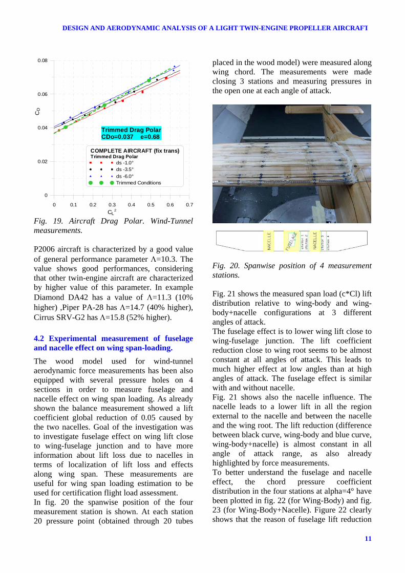
Trimmed Drag PolarCDo=0.037 e=0.68
Fig. 19. Aircraft Drag Polar. Wind-Tunnel measurements. P2006 aircraft is characterized by a good value of general performance parameter Λ=10.3. The value shows good performances, considering that other twin-engine aircraft are characterized by higher value of this parameter. In example Diamond DA42 has a value of Λ=11.3 (10% higher) ,Piper PA-28 has Λ=14.7 (40% higher), Cirrus SRV-G2 has Λ=15.8 (52% higher).
4.2 Experimental measurement of fuselage and nacelle effect on wing span-loading.
The wood model used for wind-tunnel aerodynamic force measurements has been also equipped with several pressure holes on 4 sections in order to measure fuselage and nacelle effect on wing span loading. As already shown the balance measurement showed a lift coefficient global reduction of 0.05 caused by the two nacelles. Goal of the investigation was to investigate fuselage effect on wing lift close to wing-fuselage junction and to have more information about lift loss due to nacelles in terms of localization of lift loss and effects along wing span. These measurements are useful for wing span loading estimation to be used for certification flight load assessment. In fig. 20 the spanwise position of the four measurement station is shown. At each station 20 pressure point (obtained through 20 tubes
placed in the wood model) were measured along wing chord. The measurements were made closing 3 stations and measuring pressures in the open one at each angle of attack.
Fig. 20. Spanwise position of 4 measurement stations. Fig. 21 shows the measured span load (c*Cl) lift distribution relative to wing-body and wing-body+nacelle configurations at 3 different angles of attack. The fuselage effect is to lower wing lift close to wing-fuselage junction. The lift coefficient reduction close to wing root seems to be almost constant at all angles of attack. This leads to much higher effect at low angles than at high angles of attack. The fuselage effect is similar with and without nacelle. Fig. 21 shows also the nacelle influence. The nacelle leads to a lower lift in all the region external to the nacelle and between the nacelle and the wing root. The lift reduction (difference between black curve, wing-body and blue curve, wing-body+nacelle) is almost constant in all angle of attack range, as also already highlighted by force measurements. To better understand the fuselage and nacelle effect, the chord pressure coefficient distribution in the four stations at alpha=4° have been plotted in fig. 22 (for Wing-Body) and fig. 23 (for Wing-Body+Nacelle). Figure 22 clearly shows that the reason of fuselage lift reduction

L. PASCALE, F. NICOLOSI
12
close to wing root (station 1) is a lower pressure coefficient (more suction) on wing lower surface close to the fuselage. In fact pressure on wing upper surface does not seem to be modified in a relevant way for the 4 different stations. Figure 23 shows that the nacelle leads to higher suction on upper wing surface at both sides of nacelle (station 2 and 3). The global lift reduction due to the nacelle (comparison between fig. 22 and fig. 23) in all stations is due to slightly higher pressure on the upper surface between half-chord and trailing edge and relevant lower pressures on the lower surface due to nacelle. This lower pressure is due to the flow acceleration on both sides of the nacelle.
0.2 0.4 0.6 0.8 1
0
0.4
0.8
1.2
c*Cl
alfa 0_wbodyalfa 0_wbody+nacellealfa 4_wbodyalfa 4_wbody+nacellealfa 10_wbodyalfa 10_wbody+nacelle
Fig. 21. Lift measurement at 4 stations. Wing-Body and Wing-Body+nacelle.
0 0.2 0.4 0.6 0.8 1
0.8
0.4
0
-0.4
-0.8
-1.2
-1.6
WING-BODYCp alpha=4°
st. 4st. 3st. 2st. 1
Cp
x/c Fig. 22. Pressure measurements at four stations. Wing-Body. Alpha=4°.
0 0.2 0.4 0.6 0.8 1
0.8
0.4
0
-0.4
-0.8
-1.2
-1.6
WING-BODY + NACELLECp alpha=4°
st. 4st. 3st. 2st. 1
Cp
x/c Fig. 23. Pressure measurements at four stations. Wing-Body+Nacelle. Alpha=4°.
4.3 Numerical aerodynamic calculation of fuselage and nacelle effect.
Some aerodynamic calculations have been performed on wing-body and wing-body+nacelle configurations using a 3D standard panel method to confirm wind-tunnel test results and to extend span load estimation up to wing tip. In fig. 24 an example of calculated pressure distribution on wing-body + nacelle is shown.
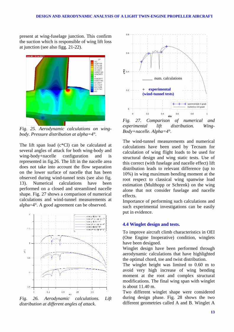
Fig. 24. Aerodynamic calculations on wing-body+nacelle. Fig. 25 shows pressure distribution on wing-body configuration at alpha=4°. The picture clearly shows that a negative pressure area is
Alpha=0°
Alpha=4°
Alpha=10°
13
DESIGN AND AERODYNAMIC ANALYSIS OF A LIGHT TWIN-ENGINE PROPELLER AIRCRAFT
present at wing-fuselage junction. This confirm the suction which is responsible of wing lift loss at junction (see also figg. 21-22).
Fig. 25. Aerodynamic calculations on wing-body. Pressure distribution at alpha=4°. The lift span load (c*Cl) can be calculated at several angles of attack for both wing-body and wing-body+nacelle configuration and is represented in fig.26. The lift in the nacelle area does not take into account the flow separation on the lower surface of nacelle that has been observed during wind-tunnel tests (see also fig. 13). Numerical calculations have been performed on a closed and streamlined nacelle shape. Fig. 27 shows a comparison of numerical calculations and wind-tunnel measurements at alpha=4°. A good agreement can be observed.
Fig. 26. Aerodynamic calculations. Lift distribution at different angles of attack.
0 0.2 0.4 0.6 0.8 1eta
0
0.2
0.4
0.6
0.8
c*C
l
sperimentale 4 gradinumerico 3.8 gradi
Fig. 27. Comparison of numerical and experimental lift distribution. Wing-Body+nacelle. Alpha=4°. The wind-tunnel measurements and numerical calculations have been used by Tecnam for calculation of wing flight loads to be used for structural design and wing static tests. Use of this correct (with fuselage and nacelle effect) lift distribution leads to relevant difference (up to 10%) in wing maximum bending moment at the root respect to classical wing spanwise load estimation (Multhopp or Schrenk) on the wing alone that not consider fuselage and nacelle effects. Importance of performing such calculations and such experimental investigations can be easily put in evidence.
4.4 Winglet design and tests. To improve aircraft climb characteristics in OEI (One Engine Inoperative) condition, winglets have been designed. Winglet design have been performed through aerodynamic calculations that have highlighted the optimal chord, toe and twist distribution. The winglet height was limited to 0.60 m to avoid very high increase of wing bending moment at the root and complex structural modifications. The final wing span with winglet is about 11.40 m. Two different winglet shape were considered during design phase. Fig. 28 shows the two different geometries called A and B. Winglet A
_____ num. calculations
+ experimental (wind-tunnel tests)

L. PASCALE, F. NICOLOSI
14
differs from Winglet B for the winglet position and consequently for the shape of fairing between wing tip and winglet. Fig. 29 shows the section lift coefficient distribution along wing span at global wing lift coefficient CL=0.80 for the wing without the winglet and for wing with winglet A and with winglet B. For the two winglets the spanwise position was assumed to be the curvilinear distance yS (also obtained rotating the winglet in the wing plane). Both winglet were initially considered with toe angle=0. The graph clearly show that the configuration A needs some negative toe angle at winglet root in order to lower lift coefficient in that region and avoid flow separation at higher angles of attack.
Fig. 28.Winglet A and Winglet B.
Fig. 29.Lift coefficient distribution along wing span.
In fig. 30 the same calculations with different toe angles shows that both shapes can lead to very similar lift distributions. For the chosen “A” configuration, toe angle up to -7° are necessary.
Fig. 30. Lift coefficient distribution along wing span. Winglet A and B with toe angles. The winglet A with toe angle=-7° and linear twist of 3° along winglet span leads to a good lift distribution. In fig. 31 the lift (responsible for induced drag) distribution is shown for the original wing and for the wing with winglets.
Fig. 31. Lift (and circulation) distribution along wing span. Winglet A and B with right toe angles. Fig. 32 shows a 3-D plot of pressure distribution on the wing tip area in climb conditions (CL close to 0.80).
WINGLET A
WINGLET B

15
DESIGN AND AERODYNAMIC ANALYSIS OF A LIGHT TWIN-ENGINE PROPELLER AIRCRAFT
Fig. 32. Pressure distribution on the winglet. Alpha=6.5°, CL=0.80. The calculated induced drag factor of wing with winglet is about 15% higher than that one of the original wing. The Oswald factor e (also considering drag arising from nacelle and other viscous contributions) estimated from wind-tunnel tests and confirmed by first flight tests results for the aircraft without winglets were closed to 0.70. The estimated Oswald factor for the aircraft with the previous shown winglets is close to 0.84. This value has been confirmed by flight tests results (especially climb characteristics). The maximum rate of climb of the aircraft in OEI condition and at maximum take-off weight has been improved from 160 ft/min up to 300 ft/min with the addition of the winglets.
5 Conclusions
Design activities concerning P2006 aircraft have been presented. The paper highlights all main aspects that have leaded to the chosen configuration. Comparison with other 4-seats aircraft has been illustrated. Results of a deep wind-tunnel test campaign performed at Department of Aerospace Engineering have been shown. All evaluated performances based on wind-tunnel tests show good potentiality for the aircraft that Particular importance has been devoted to the evaluation (also performed through numerical methodologies) of fuselage and nacelle aerodynamic influence. A deep analysis of wing span load has been performed
and presented. Some aspects of winglet design have been shown.
References [1] D.P. Coiro, F. Marulo, F. Nicolosi, F. Ricci,
"Numerical, Wind Tunnel and Flight Tests for P92J and P96 Light Aircraft”, XXI I.C.A.S. Conference, Melbourne, AUSTRALIA, Sept. 1998
[2] Nicolosi F., Pascale L. “P2002 light aircraft design: evolution of a low-wing ULM. Aerodynamics, performance, stability and flight dynamics”, XVII congresso AIDAA, Rome (Italy), 15-18 Settembre 2003
[3] W.B.Oswald, “General formulas and charts for the calculation of aircraft performance“, NACA TR-408, 1932.
[4] Nicolosi F., “Prove in galleria del vento del modello di aeromobile P2006”, Report della convenzione di ricerca tra Tecnam e Dipartimento di Progettazione Aeronautica, luglio 2006.
[5] L. Pascale, F. Marulo, F. Ricci, “Design and Testing for Ultralight Airplanes”, V Congresso Nazionale della Società Italiana di Matematica Applicata e Industriale, Ischia (Italy) ,5-9 June 2000.
[6] D. P. Coiro, V. Giordano, F. Nicolosi, “Methodologies Applied to Light Aircraft Design”, V Congresso Nazionale della Società Italiana di Matematica Applicata ed Industriale, Ischia (Italy) , 5-9 June 2000.
[7] D.P. Coiro, F. Nicolosi, S. Figliolia, F. Grasso , A. De Marco, N. Genito; “Design of a STOL ultralight aircraft in composite material”, XVIII Congresso Nazionale AIDAA, Volterra (Italy), 19-22 Settembre 2005.
[8] Coiro D.P., Nicolosi F., De Marco A., Genito N. and Figliolia S. “Design of a Low Cost Easy-to-Fly STOL Ultralight Aircraft In Composite Material”, Acta Polytecnica, Vol. 45 no. 4/2005, pp. 73-80.
[9] D.P. Coiro, F. Nicolosi, A. De Marco, F. Scherillo, F. Grasso, “High-lift systems for STOL ultralight aircraft, design and wind-tunnel tests”, XIX Congresso AIDAA, Forlì (Italy), September 2007.
Copyright Statement The authors confirm that they, and/or their company or institution, hold copyright on all of the original material included in their paper. They also confirm they have obtained permission, from the copyright holder of any third party material included in their paper, to publish it as part of their paper. The authors grant full permission for the publication and distribution of their paper as part of the ICAS2008 proceedings or as individual off-prints from the proceedings.