actuator controls ac 01.2/acexc 01 - auma.se · modbus rtu modbus tcp/ip foundation fieldbus hart...
TRANSCRIPT

Control
→ Parallel
Profibus
Modbus RTU
Modbus TCP/IP
Foundation Fieldbus
HART
Actuator controls
AC 01.2/ACExC 01.2
Operation and settingManual

Read operation instructions first.● Observe safety instructions.
Purpose of the document:
This document contains information for the commissioning, operation and maintenance staff. It is intended tosupport local device operation and setting modifications.
Reference documents:● Operation instructions (Assembly, operation, commissioning) for actuator.
Reference documents can be downloaded from the Internet (www.auma.com) or ordered directly from AUMA(refer to <Addresses>).
Table of contents Page
81. Safety instructions.................................................................................................................81.1. Basic information on safety81.2. Range of application91.3. Warnings and notes91.4. References and symbols
102. Identification...........................................................................................................................102.1. Name plate112.2. Short description
133. Operation................................................................................................................................133.1. Local actuator operation143.2. Actuator operation from remote143.3. Menu navigation via push buttons (for settings and indications)153.3.1. Menu layout and navigation163.4. User level, password 163.4.1. Password entry173.4.2. Password change173.5. Language in the display173.5.1. Language change
194. Indications..............................................................................................................................194.1. Indications during commissioning194.2. Indications in the display 204.2.1. Feedback indications from actuator and valve234.2.2. Status indications according to AUMA classification244.2.3. Status indications according to NAMUR recommendation254.3. Indication lights of local controls264.3.1. Indication lights: change colour
275. Signals (output signals).........................................................................................................275.1. Status signals via output contacts (digital outputs)275.1.1. Assignment of outputs275.1.2. Coding the outputs275.2. Configurable status signals295.3. Analogue signals (analogue outputs)295.3.1. Assignment of analogue output 1305.3.2. Signal range of analogue output 1 305.3.3. Adjustment of analogue output 1
2
Actuator controlsTable of contents AC 01.2/ACExC 01.2

305.3.4. Assignment of analogue output 2305.3.5. Signal range of analogue output 2315.3.6. Adjustment of analogue output 2
326. Operation ...............................................................................................................................326.1. Operation mode Off 326.2. Operation mode Local326.2.1. Push-to-run operation or self-retaining Local336.3. Operation mode Remote336.3.1. Push-to-run operation or self-retaining Remote356.4. Operation mode EMERGENCY356.5. Operation mode EMERGENCY stop 356.6. Operation mode Disabled356.7. Operation mode Service
377. Basic settings for commissioning........................................................................................377.1. Type of seating for end positions377.1.1. Type of seating: set387.2. Torque switching397.2.1. Torque switching: set407.3. Limit switching407.3.1. Limit switching: set427.4. Date and time427.5. Display formats427.5.1. Date format437.5.2. Time format437.5.3. Number format437.5.4. Torque unit437.5.5. Temperature unit437.5.6. Position units447.5.7. Process factor units457.5.8. Analogue working value units (AIN)457.5.9. Analogue signal output units (AIN)457.6. Contrast
468. Application functions.............................................................................................................468.1. Intermediate positions (pivot points)468.1.1. Intermediate positions (pivot points): define 468.1.2. Signal behaviour of intermediate positions: set478.1.3. Hysteresis for intermediate positions: set488.2. Operation profile (operation behaviour) for intermediate positions488.2.1. Operation profile: activate488.2.2. Operation behaviour for intermediate positions (pivot points): set498.2.3. Off times for intermediate positions (pivot points): set 498.3. Two-wire control508.4. Positioner (operation mode Remote SETPOINT) 508.4.1. Positioner: activate508.4.2. Adaptive behaviour: switch on or off 518.4.3. Overrun (inner dead band): set manually 518.4.4. Max. error variable (outer dead band): set manually 528.4.5. Dead time: set 528.4.6. Hysteresis for positioner: set
3
Actuator controls AC 01.2/ACExC 01.2 Table of contents

528.4.7. Closing fully/opening fully (end position tolerance for setpoint) 538.4.8. Setting range: limit538.4.9. Change-over between OPEN - CLOSE control and setpoint control548.4.10. Input of setpoint position548.4.11. Input range of setpoint position548.4.12. Split Range operation558.5. Process controller 568.5.1. Process controller activation568.5.2. Process controller: set modulating behaviour578.5.3. Setpoint source (input for process setpoint)588.5.4. Behaviour on loss of process setpoint588.5.5. Inverse operation588.5.6. Internal process setpoint598.5.7. Setting procedure598.5.8. Proportional amplification Kp: set598.5.9. Reset time Ti: set598.5.10. Rate time Td: set608.5.11. Actual value source (input for actual process value)608.6. Stepping mode 608.6.1. Stepping mode: activate618.6.2. Operation mode for stepping mode 618.6.3. Start and end of stepping mode618.6.4. On times and off times 628.7. By-pass function638.7.1. Bypass function: activate648.7.2. By-pass application: configure648.8. Lift Plug Valve (LPV)678.8.1. LPV function: activate678.8.2. LPV actuator type: configure678.8.3. Delay time of master LPV actuator: configure688.8.4. Delay time of slave LPV actuator: configure688.9. Multiport valve function (operation to position)688.9.1. Multiport valve function: activate698.9.2. Actuator type: set/check698.9.3. Gear reduction ratio: set/check698.9.4. Number of ports (positions)708.9.5. Home port (zero position): set708.9.6. Positions (of valve ports): define/check718.9.7. Operate to position via push buttons of the local controls728.9.8. Operate to position from Remote728.9.9. Dead band728.9.10. Backlash compensation738.9.11. Signalling behaviour of positions: set/check738.9.12. Hysteresis for signalling intermediate positions: set748.10. Automatic deblocking758.10.1. Automatic deblocking function: activate758.10.2. Operation time for operation in opposite direction: set758.10.3. Number of deblocking attempts: set758.10.4. Tolerance range: set758.11. Heater system and heaters
4
Actuator controlsTable of contents AC 01.2/ACExC 01.2

768.11.1. Heater system within the actuator controls768.11.2. Heater on control unit (actuator)768.11.3. Motor heater
779. Failure functions....................................................................................................................779.1. Reversing prevention time779.2. Failure behaviour on loss of signal779.2.1. Failure behaviour initiation on loss of signal779.2.2. Failure source (failure reason) for a failure operation: set789.2.3. Failure operation (reaction of the actuator) on loss of signal789.2.4. Failure position: define789.2.5. Failure position MPV: define799.2.6. Delay time: set799.3. EMERGENCY behaviour809.3.1. EMERGENCY behaviour: activate809.3.2. EMERGENCY failure behaviour819.3.3. Failure source (failure reason) for an EMERGENCY operation: set819.3.4. Operation mode for EMERGENCY behaviour819.3.5. EMERGENCY operation829.3.6. EMERGENCY position829.3.7. EMERGENCY position MPV829.3.8. Torque switching: by-pass 829.3.9. Motor protection: by-pass 839.3.10. Stepping mode: by-pass 839.3.11. Operation profile: by-pass 839.3.12. Interlock: by-pass 839.3.13. Local stop: by-pass 849.3.14. Delay time for EMERGENCY operation849.4. Enabling local controls849.4.1. Enabling function: activate859.4.2. Enabling function behaviour859.5. Priority REMOTE869.5.1. Priority REMOTE: activate869.5.2. Priority REMOTE behaviour869.6. Interlock (enabling operation commands)879.6.1. Interlock: activate879.6.2. Failure source of Interlock enable signal: set879.6.3. Operation mode for interlock879.6.4. Interlock behaviour (running direction)889.7. Local Stop889.7.1. Behaviour889.8. EMERGENCY stop function899.9. Partial Valve Stroke Test (PVST)909.9.1. PVST: activate909.9.2. Operation mode for PVST919.9.3. Behaviour for PVST: define919.9.4. Partial stroke for PVST: set919.9.5. PVST monitoring time: set919.9.6. PVST operating time: set919.9.7. PVST reverse time: set929.9.8. PVST reminder
5
Actuator controls AC 01.2/ACExC 01.2 Table of contents

9310. Monitoring functions..............................................................................................................9310.1. Torque monitoring 9410.2. Motor protection monitoring (thermal monitoring) 9510.3. Type of duty monitoring (motor starts and running time)9610.4. Operating time monitoring 9710.5. Reaction monitoring 9710.6. Motion detector 9710.6.1. Motion detector: activate9810.6.2. Detection time dt9810.6.3. Travel difference dx9810.6.4. Delay time9810.7. Monitoring of electronics power supply9910.8. Temperature monitoring9910.9. Heater system/heater monitoring
10010.10. Verification of sub-assemblies10110.11. Phase failure monitoring10110.12. Phase sequence detection and correction of the direction of rotation
10211. Functions: activate and enable.............................................................................................10211.1. Activate functions10211.2. Enable functions
10412. Service functions...................................................................................................................10412.1. Direction of rotation10412.2. Factory setting10512.3. Languages: reload10512.4. Data export10512.5. Data import10612.6. Actual configuration: accept10612.7. Firmware update10612.8. Service software AUMA CDT (Bluetooth)
10813. Diagnostics.............................................................................................................................10813.1. Electronic device ID10813.2. Diagnostic Bluetooth connection10913.3. Diagnostic Interface11013.4. Diagnostic Position transmitter potentiometer11013.5. Diagnostic Position transmitter RWG11113.6. Diagnostic Position transmitter MWG11113.7. Diagnostic positioner11113.8. Diagnostic On time monitoring11213.9. Diagnostic Process controller11213.10. Diagnostic FQM (fail safe)11213.11. Simulation (inspection and test function)11213.11.1. Actuator signals11313.11.2. Interface signals
11414. Plant Asset Management.......................................................................................................11414.1. Operating data11514.2. Event report11614.3. Characteristics11614.3.1. Torque-travel characteristic11814.3.2. Position-time characteristic
6
Actuator controlsTable of contents AC 01.2/ACExC 01.2

11914.3.3. Temperature-time characteristic11914.4. Histograms11914.4.1. Motor running time-position (histogram)12014.4.2. Motor running time-temperature (histogram)12114.4.3. Acceleration-frequency (histogram)12114.4.4. Motor running time-torque (histogram)12214.5. Maintenance (information and signals)12414.6. Operating times: display12414.7. Device temperatures: display
12515. Corrective action....................................................................................................................12515.1. Primary fuses12515.2. Fault indications and warning indications
13316. Appendix.................................................................................................................................13316.1. Selection overview for output contacts and indication lights (digital outputs DOUT)13516.2. Selection overview of binary signals for digital inputs (DIN)
137Index........................................................................................................................................
141Parameter index.....................................................................................................................
146Addresses...............................................................................................................................
7
Actuator controls AC 01.2/ACExC 01.2 Table of contents

1. Safety instructions
1.1. Basic information on safety
Standards/directives AUMA products are designed and manufactured in compliance with recognisedstandards and directives. This is certified in a Declaration of Incorporation and a ECDeclaration of Conformity.
The end user or the contractor must ensure that all legal requirements, directives,guidelines, national regulations and recommendations with respect to assembly,electrical connection, commissioning and operation are met at the place of installation.
They include among others:
● Standards and directives such as: EN 60079 “Electrical apparatus for explosivegas atmospheres" –- Part 14: Electrical installations in hazardous areas (other than mines).- Part 17: Inspection and maintenance of electrical installations in hazardous
areas (other than mines).
Safety instructions/warn-ings
All personnel working with this device must be familiar with the safety and warninginstructions in this manual and observe the instructions given. Safety instructionsand warning signs on the device must be observed to avoid personal injury or propertydamage.
Qualification of staff Assembly, electrical connection, commissioning, operation, and maintenance mustbe carried out exclusively by suitably qualified personnel having been authorised bythe end user or contractor of the plant only.
Prior to working on this product, the staff must have thoroughly read and understoodthese instructions and, furthermore, know and observe officially recognised rulesregarding occupational health and safety.
Work performed in potentially explosive atmospheres is subject to special regulationswhich have to be observed. The end user or contractor of the plant are responsiblefor respect and control of these regulations, standards, and laws.
Commissioning Prior to commissioning, it is important to check that all settings meet the requirementsof the application. Incorrect settings might present a danger to the application, e.g.cause damage to the valve or the installation. The manufacturer will not be heldliable for any consequential damage. Such risk lies entirely with the user.
Operation Prerequisites for safe and smooth operation:
● Correct transport, proper storage, mounting and installation, as well as carefulcommissioning.
● Only operate the device if it is in perfect condition while observing these instruc-tions.
● Immediately report any faults and damage and allow for corrective measures.● Observe recognised rules for occupational health and safety.● Observe the national regulations.
Protective measures The end user or the contractor are responsible for implementing required protectivemeasures on site, such as enclosures, barriers, or personal protective equipmentfor the staff.
Maintenance Any device modification requires the consent of the manufacturer.
1.2. Range of application
AUMA actuator controls are exclusively designed for the operation of AUMA actuators.
Other applications require explicit (written) confirmation by the manufacturer. Thefollowing applications are not permitted, e.g.:
● motor control● pump controlNo liability can be assumed for inappropriate or unintended use.
8
Actuator controlsSafety instructions AC 01.2/ACExC 01.2

Observance of these operation instructions is considered as part of the device'sdesignated use.
1.3. Warnings and notes
The following warnings draw special attention to safety-relevant procedures in theseoperation instructions, each marked by the appropriate signal word (DANGER,WARNING, CAUTION, NOTICE).
Indicates an imminently hazardous situation with a high level of risk. Failureto observe this warning could result in death or serious injury.
Indicates a potentially hazardous situation with a medium level of risk. Failureto observe this warning could result in death or serious injury.
Indicates a potentially hazardous situation with a low level of risk. Failure toobserve this warning may result in minor or moderate injury. May also be usedwith property damage.
Potentially hazardous situation. Failure to observe this warning may result inproperty damage. Is not used for personal injury.
Arrangement and typographic structure of the warnings
Type of hazard and respective source!
Potential consequence(s) in case of non-observance (option)
→ Measures to avoid the danger→ Further measure(s)
Safety alert symbol warns of a potential personal injury hazard.
The signal word (here: DANGER) indicates the level of hazard.
1.4. References and symbols
The following references and symbols are used in these instructions:
Information The term Information preceding the text indicates important notes and information.
Symbol for CLOSED (valve closed)
Symbol for OPEN (valve open)
Important information before the next step. This symbol indicates what is requiredfor the next step or what has to be prepared or observed.
Via the menu to parameter
Describes the path within the menu to the parameter. By using the push buttons ofthe local controls you may quickly find the desired parameter in the display.
< > Reference to other sections
Terms in brackets shown above refer to other sections of the document which providefurther information on this topic.These terms are either listed in the index, a headingor in the table of contents and may easily be located.
9
Actuator controls AC 01.2/ACExC 01.2 Safety instructions

2. Identification
2.1. Name plate
Each device is equipped with a name plate.
Figure 1: Arrangement of name plate
[1] Actuator controls name plate
Description of actuator controls name plate
Figure 2: Actuator controls name plate
[1] Type designation[2] Order number[3] Serial number[4] Actuator terminal plan[5] Actuator controls terminal plan[6] Mains voltage[7] AUMA power class for switchgear[8] Permissible ambient temperature[9] Enclosure protection[10] Control[11] Data Matrix code
Descriptions
Type designation Type and size
These instructions apply to the following devices types and sizes:
Types: AC/ACExC = AUMATIC actuator controls
Size: 01.2
Versions: Intrusive and Non-Intrusive
Order number The product can be identified using this number and the technical data as well asorder-related data pertaining to the device can be requested.
Please always state this number for any product inquiries.
On the Internet at http://www.auma.com, we offer a service allowing authorisedusers to download order-related documents such as wiring diagrams and technicaldata (both in German and English), inspection certificates and the operationinstructions when entering the order number.
10
Actuator controlsIdentification AC 01.2/ACExC 01.2

Serial number Table 1: Description of serial number (with example)
MD123451405Position 1+ 2: Assembly in week
Week 0505
Position 3 +4 :Year of productionYear of production: 201414
All other positionsInternal number for unambiguous product identificationMD12345
Actuator controls termin-al plan
Position 9 in the TPA wiring diagram: Position transmitter (actuator):
Control unit: electromechanical:
0 = Without position transmitter
A, B, J, K, L, N = Potentiometer
C, D, E, G, H, M, S = EWG/RWG (electronic position transmitter)
Control unit: electronic:
I = MWG (Magnetic limit and torque transmitter)
AUMA power class forswitchgear
The switchgear used in the actuator controls (reversing contactors/thyristors) areclassified according to AUMA power classes (e.g. A1, B1, ....). The power classdefines the max. permissible rated power (of the motor) the switchgear has beendesigned for. The rated power (nominal power) of the actuator motor is indicated inkW on the motor name plate. For the assignment of the AUMA power classes to thenominal power of the motor types, refer to the separate electrical data sheets.
For switchgear without assignment to any power classes, the actuator controls nameplate does not indicate the power class but the max. rated power in kW.
Control Table 2: Control examples (indications on controls name plate)
DescriptionInput signalControl voltage 24 V DC for OPEN - CLOSE control via digital inputs(OPEN, STOP, CLOSE)
24 V DC
Control voltage 115 V AC for OPEN - CLOSE control via digital inputs(OPEN, STOP, CLOSE)
115 V AC
Input current for setpoint control via analog input0/4 – 20 mA
Data Matrix code When registered as authorised user, you may use the AUMA Support App to scanthe Data Matrix code and directly access the order-related product documents withouthaving to enter order number or serial number.
Figure 3: Link to the App store:
2.2. Short description
Actuator controls AUMATIC actuator controls are used to operate AUMA actuators and are suppliedready for use. The controls may be mounted directly to the actuator or separatelyon a wall bracket.
The functions of the AUMATIC controls include standard valve control in OPEN -CLOSE duty, positioning, process control, logging of operating data right through todiagnostic functions.
Local con-trols/AUMA CDT
Operation, setting, and display can be performed on site directly at the controls.
When set to local control, it is possible to
11
Actuator controls AC 01.2/ACExC 01.2 Identification

● operate the actuator via the local controls (push buttons and display) and performsettings (contents of these instructions).
● read in or out data or modify and save settings via the AUMA CDT software(accessories), using a computer (laptop or PC). The connection between com-puter and AUMATIC is wireless via Bluetooth interface (not included in theseinstructions).
Intrusive - Non-Intrusive ● Intrusive version (control unit: electromechanical):Limit and torque setting is performed via switches in the actuator.
● Non-Intrusive version (control unit: electronic):Limit and torque setting is performed via the controls, actuator and controlshousings do not have to be opened. For this purpose, the actuator is equippedwith an MWG (magnetic limit and torque transmitter), also supplying analoguetorque feedback signals/torque indication and analogue position feedback sig-nals/position indication.
12
Actuator controlsIdentification AC 01.2/ACExC 01.2

3. Operation
Valve damage due to incorrect basic setting!
→ Prior to electrical operation of the actuator, the basic settings i.e. type of seating,torque and limit switching have to be completed.
3.1. Local actuator operation
Local actuator operation is performed using the push buttons of the local controls ofthe AC.
Figure 4: Local controls
[1] Push button for operation command in direction OPEN[2] Push button STOP[3] Push button for operation command in direction CLOSE[4] Push button RESET[5] Selector switch
Hot surfaces, e.g. possibly caused by high ambient temperatures or strongdirect sunlight!
Danger of burns
→ Check surface temperature and wear protective gloves, if required.
→ Set selector switch [5] to position Local control (LOCAL).
➥ The actuator can now be operated using the push buttons [1 – 3]:
- Run actuator in direction OPEN: Press push button [1] .- Stop actuator: Press push button STOP [2].- Run actuator in direction CLOSE: Press push button [3] .
Information The OPEN - CLOSE operation commands can be given either in push-to-run or inself-retaining operation mode. For further information, please refer to <Push-to-runoperation or self-retaining local> chapter.
13
Actuator controls AC 01.2/ACExC 01.2 Operation

3.2. Actuator operation from remote
→ Set selector switch to position Remote control (REMOTE).
➥ Now, it is possible to operate the actuator via remote control, via operationcommands (OPEN, STOP, CLOSE) or analogue setpoints (e.g. 0 – 20 mA).
Information For actuators equipped with a positioner, it is possible to change over between OPEN- CLOSE control (Remote OPEN-CLOSE) and setpoint control (Remote SET-POINT). For further information, refer to chapter <Change-over between OPEN -CLOSE control and setpoint control>.
3.3. Menu navigation via push buttons (for settings and indications)
Menu navigation for display and setting is made via the push buttons [1 – 4] of thelocal controls.
Set the selector switch [5] to position 0 (OFF) when navigating through the menu.
The bottom row of the display [6] serves as navigation support and explains whichpush buttons [1 – 4] are used for menu navigation.
Figure 5:
[1–4] Push buttons or navigation support[5] Selector switch[6] Display
Table 3: Important push button functions for menu navigation
FunctionsNavigation sup-port on display
Push buttons
Change screen/selectionUp ▲[1] Change values
Enter figures from 0 to 9
Change screen/selectionDown ▼[2] Change values
Enter figures from 0 to 9
14
Actuator controlsOperation AC 01.2/ACExC 01.2

FunctionsNavigation sup-port on display
Push buttons
Confirm selectionOk[3] SaveSaveEnter <Edit> menuEditDisplay more detailsDetailsEnter Main menuSetup[4] CCancel processEscReturn to previous display
Backlight ● The display is illuminated in white during normal operation. The backlight turnsto red under fault conditions.
● The screen illumination is brighter when operating a push button. If no pushbutton is operated for 60 seconds, the display will become dim again.
3.3.1. Menu layout and navigation
Groups The indications on the display are divided into 3 groups:
Figure 6: Groups
[1] Startup menu[2] Status menu[3] Main menu
ID Status menu and main menu are marked with an ID.
Figure 7: Marking with ID
S ID starts with S = status menuM ID starts with M = main menu
Group selection It is possible to select between status menu S and main menu M:
For this, set selector switch to 0 (OFF), hold down push button C for approx. 2seconds until a screen containing the ID M... appears.
Figure 8: Select menu groups
You return to the status menu if:
● the push buttons on the local controls have not been operated within 10 minutes● or by briefly pressing C
Direct display via ID When entering the ID within the main menu, screens can be displayed directly (withoutclicking through).
15
Actuator controls AC 01.2/ACExC 01.2 Operation

Figure 9: Direct display (example)
Display indicates in the bottom row: Go to1. Press push button Go to.
Display indicates: Go to menu M00002. Use push buttons Up ▲ Down ▼ to select figures 0 to 9.3. Press push button Ok to confirm first digit.4. Repeat steps 2 and 3 for all further digits.5. To cancel the process: Press C Esc.
3.4. User level, password
User level The user level defines which menu items or parameters can be displayed or modifiedby the active user.
There are 6 different user levels. The user level is indicated in the top row:
Figure 10: User level display (example)
Password A password must be entered to allow parameter modification. The display indicates:Password 0***A specific password is assigned to each user level and permits different actions.
Table 4: User levels and authorisations
Authorisation/passwordDesignation (user level)Verify settingsNo password required
Observer (1)
Change settingsDefault factory password: 0000
Operator (2)
Reserved for future extensionsMaintenance (3)Change device configuratione.g. type of seating, assignment of output contactsDefault factory password: 0000
Specialist (4)
Service staffChange configuration settings
Service (5)
AUMA administratorAUMA (6)
3.4.1. Password entry
1. Select desired menu and hold down push button for approx. 3 seconds.
➥ Display indicates the set user level, e.g Observer (1)2. Press Up ▲to select a higher user level and press Ok to confirm.
➥ Display shows: Password 0***3. Use push buttons Up ▲ Down ▼ to select figures 0 to 9.4. Confirm first digit of password via push button Ok.5. Repeat steps 1 and 2 for all further digits.
➥ Having confirmed the last digit with Ok, access to all parameters within oneuser level is possible if the password entry is correct.
16
Actuator controlsOperation AC 01.2/ACExC 01.2

3.4.2. Password change
Only the passwords of same or lower user level may be changed.
Example:The user is signed in as Specialist (4).This authorises him or her to modifythe passwords between user levels (1) to (4).
Device configuration M0053Service functions M0222Change passwords M0229
Menu point Service functions M0222 is only visible if user level has been set toSpecialist (4) or higher.
Select main menu 1. Set selector switch to position 0 (OFF).
2. Press push button C Setup and hold it down for approx. 3 seconds.
➥ Display goes to main menu and indicates: ▶ Display...Change passwords 3. Select parameter Change passwords either:
→ click via the menu to parameter, or→ via direct display: press and enter ID M0229
- Display indicates: ▶ Change passwords- The user level is indicated in the top row (1 – 6), e.g.:
- For user level 1 (view only), passwords cannot be changed. To change pass-words, you must change to a higher user level. For this, enter a password viaa parameter.
4. For a user level between 2 and 6: Press push button Ok.
➥ The display indicates the highest user level, e.g.: For user 45. Select user level via push buttons Up ▲ Down ▼ and confirm with Ok.
➥ Display indicates: ▶ Change passwords Password 0***6. Enter current password (→ enter password).
➥ Display indicates: ▶ Change passwords Password (new) 0***7. Enter new password (→ enter password).
➥ Display indicates: ▶ Change passwords For user 4 (example)
8. Select next user level via push buttons Up ▲ Down ▼ or cancel the processvia Esc.
3.5. Language in the display
The AUMATIC display is multilingual.
3.5.1. Language change
Display... M0009Language M0049
Select main menu 1. Set selector switch to position 0 (OFF).
17
Actuator controls AC 01.2/ACExC 01.2 Operation

2. Press push button C Setup and hold it down for approx. 3 seconds.
➥ Display goes to main menu and indicates: ▶ Display...Change language 3. Press Ok.
➥ Display indicates: ▶ Language4. Press Ok.
➥ Display indicates the selected language, e.g.: ▶ Deutsch5. The bottom row of the display indicates:
→ Save → continue with step 10→ Edit → continue with step 6
6. Press Edit.➥ Display indicates: ▶ Observer (1)7. Select user level via Up ▲ Down ▼ resulting in the following significations:
→ black triangle: ▶ = current setting→ white triangle: ▷ = selection (not saved yet)
8. Press Ok.
➥ Display indicates: Password 0***9. Enter password (→ enter password).
➥ Display indicates: ▶ Language and Save (bottom row)
Language selection 10. Select new language via Up ▲ Down ▼ resulting in the following significa-tions:
→ black triangle: ▶ = current setting→ white triangle: ▷ = selection (not saved yet)
11. Confirm selection via Save.
➥ The display changes to the new language.The new language selection is saved.
18
Actuator controlsOperation AC 01.2/ACExC 01.2
4. Indications
4.1. Indications during commissioning
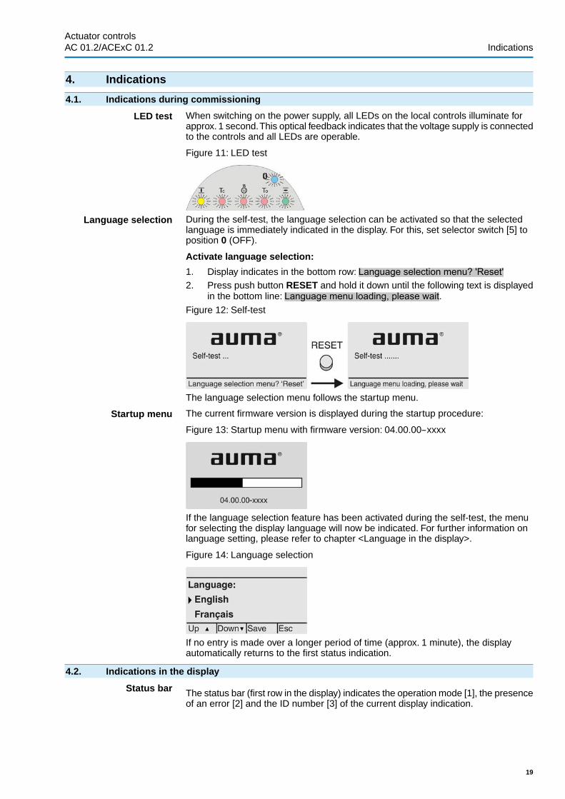
LED test When switching on the power supply, all LEDs on the local controls illuminate forapprox. 1 second.This optical feedback indicates that the voltage supply is connectedto the controls and all LEDs are operable.
Figure 11: LED test
Language selection During the self-test, the language selection can be activated so that the selectedlanguage is immediately indicated in the display. For this, set selector switch [5] toposition 0 (OFF).
Activate language selection:
1. Display indicates in the bottom row: Language selection menu? 'Reset'2. Press push button RESET and hold it down until the following text is displayed
in the bottom line: Language menu loading, please wait.Figure 12: Self-test
The language selection menu follows the startup menu.
Startup menu The current firmware version is displayed during the startup procedure:
Figure 13: Startup menu with firmware version: 04.00.00–xxxx
If the language selection feature has been activated during the self-test, the menufor selecting the display language will now be indicated. For further information onlanguage setting, please refer to chapter <Language in the display>.
Figure 14: Language selection
If no entry is made over a longer period of time (approx. 1 minute), the displayautomatically returns to the first status indication.
4.2. Indications in the display
Status bar The status bar (first row in the display) indicates the operation mode [1], the presenceof an error [2] and the ID number [3] of the current display indication.
19
Actuator controls AC 01.2/ACExC 01.2 Indications

Figure 15: Information in the status bar (top)
[1] Operation mode[2] Error symbol (only for faults and warnings)[3] ID number: S = Status page
Navigation support If further details or information are available with reference to the display, the followingindications Details or More appear in the navigation support (bottom display row).Then, further information can be displayed via the push button.
Figure 16: Navigation support (bottom)
[1] shows list with detailed indications[2] shows further available information
The navigation support (bottom row) is faded out after approx. 3 seconds. Press anypush button (selector switch in position 0 (OFF)) to fade in the navigation support.
4.2.1. Feedback indications from actuator and valve
Display indications depend on the actuator version.
Valve position (S0001)
This indication is only available if a position transmitter (potentiometer, EWG, RWGor MWG) is installed in the actuator.
● S0001 on the display indicates the valve position in % of the travel.● The bargraph display appears after approx. 3 seconds.● When issuing an operation command, an arrow indicates the direction
(OPEN/CLOSE).
Figure 17: Valve position and direction of operation
Reaching the preset end positions is additionally indicated via (CLOSED) and (OPEN) symbols.
Figure 18: End position CLOSED/OPEN reached
0% Actuator is in end position CLOSED100% Actuator is in end position OPEN
20
Actuator controlsIndications AC 01.2/ACExC 01.2

Torque (S0002)
The indication is only available if the actuator is equipped with an MWG (magneticlimit and torque transmitter).
● S0002 on the display indicates the torque applied at the actuator output.● The bargraph display appears after approx. 3 seconds.
Figure 19: Torque
Select unit The push button allows to select the unit displayed (percent %, Newton metre Nmor "foot-pound" ft-lb
Figure 20: Units of torque
Display in percent 100 % indication equals the max. torque indicated on the name plate of the actuator.
Example: SA 07.6 with 20 – 60 Nm.
● 100 % corresponds to 60 Nm of nominal torque.● 50 % corresponds to 30 Nm of nominal torque.
Operation commands (S0003)
The display S0003 indicates:
● active operation commands, like e.g.: Operation in direction CLOSE or in direc-tion OPEN
● the actual value E2 as bargraph indication and as value between 0 and 100 %.● for setpoint control (positioner): setpoint E1● for stepping mode or for intermediate positions with operation profile: pivot
points and operation behaviour of pivot pointsThe navigation support (bottom row) is faded out after approx. 3 seconds and theaxis/axes for pivot point display are shown.
OPEN - CLOSE control Active operation commands (OPEN, CLOSE, ...) are shown above the bargraphdisplay. The figure below shows the operation command in direction CLOSE.
Figure 21: Display for OPEN - CLOSE control
E2 Actual position value
21
Actuator controls AC 01.2/ACExC 01.2 Indications

Setpoint control If the positioner is enabled and activated, the bargraph indication for E1 (positionsetpoint) is displayed.
The direction of the operation command is displayed by an arrow above the bargraphindication. The figure below shows the operation command in direction CLOSE.
Figure 22: Indication for setpoint control (positioner)
E1 Position setpointE2 Actual position value
Pivot point axis The pivot points and their operation behaviour (operation profile) are shown on thepivot point axis by means of symbols.
The symbols are only displayed if at least one of the following functions is activated:
Operation profile M0294Timer CLOSE M0156Timer OPEN M0206
Figure 23: Examples: on the left pivot points (intermediate positions); on the rightstepping mode
Table 5: Symbols along the pivot point axis
Stepping modePivot point (intermediate position)with operation profile
Symbol
End of stepping modePivot point without reaction|
Start of stepping mode in directionCLOSE
Stop during operation in directionCLOSE
Start of stepping mode in directionOPEN
Stop during operation in directionOPEN
–Stop during operation in directionsOPEN and CLOSE
–Pause for operation in direction CLOSE
–Pause for operation in direction OPEN
–Pause for operation in directions OPENand CLOSE
Multiport valve positions (S0017)
In case of active multiport valve function, the display S0017 indicates a secondbargraph display with set positions (valve connections) above the actual positionvalue E2. Positions (P1, P2, ...) are displayed with a black triangle . Push buttons
are used to select positions. Both positions and the actual position value E2 aredisplayed in degrees.
22
Actuator controlsIndications AC 01.2/ACExC 01.2

Figure 24: Status indication for multiport valve (example P4 = 180°)
P (P1, P2, ...) selected position (1, 2, ...)(– –) no position selected
E2 Actual position value
4.2.2. Status indications according to AUMA classification
These indications are available if the parameter Diagnostic classific. M0539 is setto AUMA.
Warnings (S0005)
If a warning has occurred, the display shows S0005:
● the number of warnings occurred● a blinking question mark after approx. 3 seconds
Figure 25: Warnings
For further information, please also refer to <Corrective action>.
Not ready REMOTE (S0006)
The S0006 display shows indications of the Not ready REMOTE group.
If such an indication has occurred, the display shows S0006:
● the number of indications occurred● a blinking crossbar after approx. 3 seconds
Figure 26: Not ready REMOTE indications
For further information, please also refer to <Corrective action>.
Fault (S0007)
If a fault has occurred, the display shows S0007:
● the number of faults occurred● a blinking exclamation mark after approx. 3 seconds
23
Actuator controls AC 01.2/ACExC 01.2 Indications

Figure 27: Fault
For further information, please also refer to <Corrective action>.
4.2.3. Status indications according to NAMUR recommendation
These indications are available, if the parameter Diagnostic classific. M0539 is setto NAMUR.
Out of Specification (S0008)
The S0008 indication shows out of specification indications according to NAMURrecommendation NE 107.
If such an indication has occurred, the display shows S0008:
● the number of indications occurred● a blinking triangle with question mark after approx. 3 seconds
Figure 28: Out of specification
For further information, please also refer to <Corrective action>.
Function check (S0009)
The S0009 indication shows function check indications according to NAMURrecommendation NE 107.
If an indication has occurred via the function check, the display shows S0009:
● the number of indications occurred● a blinking triangle with a spanner after approx. 3 seconds
Figure 29: Function check
For further information, please also refer to <Corrective action>.
Maintenance required (S0010)
The S0010 indication shows maintenance indications according to NAMURrecommendation NE 107.
If such an indication has occurred, the display shows S0010:
● the number of indications occurred● a blinking square with an oil can after approx. 3 seconds
24
Actuator controlsIndications AC 01.2/ACExC 01.2

Figure 30: Maintenance required
For further information, please also refer to <Corrective action>.
Failure (S0011)
The S0011 indication shows the causes of the failure indication according to NAMURrecommendation NE 107.
If such an indication has occurred, the display shows S0011:
● the number of indications occurred● a blinking circle with a cross after approx. 3 seconds
Figure 31: Failure
For further information, please also refer to <Corrective action>.
4.3. Indication lights of local controls
Figure 32: Arrangement and signification of indication lights
[1] Marking with symbols (standard)[2] Marking with figures 1 – 6 (option)
1 End position CLOSED reached (blinking: operation in direction CLOSE)
2 Tc Torque fault CLOSE
3 Motor protection tripped
4 To Torque fault OPEN
5 End position OPEN reached (blinking: operation in direction OPEN)
6 Bluetooth connection
Modify indication light assignment (indications)
Different indications can be assigned to LEDs 1 – 5.
Device configuration M0053Local controls M0159Indication light 1 (left) M0093Indication light 2 M0094Indication light 3 M0095Indication light 4 M0096Indicat. light 5 (right) M0097Signal interm. pos. M0167
Defaut values (Europe):Indication light 1 (left) = End p. CLOSED, blink
25
Actuator controls AC 01.2/ACExC 01.2 Indications

Indication light 2 = Torque fault CLOSEIndication light 3 = Thermal faultIndication light 4 = Torque fault OPENIndicat. light 5 (right) = End p. OPEN, blinkSignal interm. pos. = OPEN/CLOSED = OffFurther setting values:
Refer to <Appendix>/<Selection overview for output contacts and indication lights>
4.3.1. Indication lights: change colour
— Option —
User level required to make changes: AUMA (6)
Device configuration M0053Local controls M0159
Setting valuesDefault values for versionMenuParametersUSAEurope
YellowGreenYellow/green
GreenYellowM0838Colour ind.light 1
RedBluePurple
BlueRedM0839Colour ind.light 2
RedYellowOrange
YellowRedM0840Colour ind.light 3
RedBluePurple
BlueRedM0841Colour ind.light 4
GreenRedOrange
RedGreenM0842Colour ind.light 5
26
Actuator controlsIndications AC 01.2/ACExC 01.2

5. Signals (output signals)
5.1. Status signals via output contacts (digital outputs)
Characteristics Output contacts are used to send status signals (e.g. reaching the end positions,selector switch position, faults...) as binary signals to the control room.
Status signals only have two states: active or inactive. Active means that theconditions for the signal are fulfilled.
5.1.1. Assignment of outputs
The output contacts (outputs DOUT 1 – 12) can be assigned to various signals.
Required user level: Specialist (4) or higher.
Device configuration M0053I/O interface M0139Digital outputs M0110Signal DOUT 1 M0109
Default values:
Signal DOUT 1 = FaultSignal DOUT 2 = End position CLOSEDSignal DOUT 3 = End position OPENSignal DOUT 4 = Selector sw. REMOTESignal DOUT 5 = Torque fault CLOSESignal DOUT 6 = Torque fault OPENSignal DOUT 7 = End position CLOSEDSignal DOUT 8 = End position OPENSignal DOUT 9 = Selector sw. REMOTESignal DOUT 10 = Torque fault CLOSESignal DOUT 11 = Torque fault OPENSignal DOUT 12 = FaultFurther setting values:
Refer to <Appendix>/<Selection overview for output contacts and indication lights>
5.1.2. Coding the outputs
The output signals DOUT 1 – 12 can be set either to high active or low active.
● High active = output contact closed = signal active● Low active = output contact open = signal activeRequired user level: Specialist (4) or higher.
Device configuration M0053I/O interface M0139Digital outputs M0110Coding DOUT 1 M0102
Default values for DOUT 1 – 12: High active
5.2. Configurable status signals
The signals described here are collective signals of various other signals which canbe configured for specific users. For configuration, the individual signals can beselected from a list and activated (☑) or deactivated (☐) indivdually. The signals caneither be assigned to a digital output (output contact) or to an indication light (LED).
For detailed information on these signals, refer to <Fault signals and warnings>chapter.
Configure status signals
Required user level: Specialist (4) or higher.
27
Actuator controls AC 01.2/ACExC 01.2 Signals (output signals)

Device configuration M0053Config. of signals M0860
Failure (configurable) M0879Fault (Cfg) M0880Warnings (Cfg) M0881Not ready REMOTE (Cfg) M0882Default values Failure (configurable):☑ = activated
☑ Fault (Cfg)☑ Warning (Cfg)☑ Not ready REMOTE (Cfg)
Default values Fault (Cfg):☑ = activated
☑ Configuration error☑ Config. error REMOTE☑ Internal error☑ Torque fault CLOSE☑ Torque fault OPEN☑ Phase fault☑ Incorrect phase seq☑ Mains quality☑ Thermal fault☑ Fault no reaction
Default values Warnings (Cfg):☑ = activated
☑ Config. warning☑ Internal warning☑ Wrn input AIN 1☑ Wrn input AIN 2☑ Wrn setpoint position☑ Not used☑ Maintenance required
Default values Not ready REMOTE (Cfg):☑ = activated
☑ Wrong oper. cmd☑ Sel. sw. not REMOTE☑ Service active☑ Disabled☑ EMCY stop active☑ EMCY behav. active☑ I/O interface☑ Handwheel active☑ FailState fieldbus☑ Local STOP
28
Actuator controlsSignals (output signals) AC 01.2/ACExC 01.2

☑ Interlock by-pass☑ PVST active
5.3. Analogue signals (analogue outputs)
Conditions The actuator is equipped with a position transmitter.
Characteristics Depending on the actuator equipment, different signals, such as travel, torque oroutput speed can be recorded and issued as continuous values, e.g. 4 to 20 mA.The AC is equipped with up to two analogue outputs AOUT1 and AOUT2.
5.3.1. Assignment of analogue output 1
Designation in the wiring diagram: AOUT 1.
Required user level: AUMA (6).
Device configuration M0053I/O interface M0139Analogue outputs M0335Signal AOUT 1 M0131
Default value: Actual position
Information The signal range of the output (e.g. 0/4 – 20 mA) is set via a separate parameter(Signal range AOUT1 M0129).
Setting values:
Not used Analogue output 1 is not assigned.
Actual position Position feedback of the valve position (actual position value E2)
Condition: Position transmitter installed in the actuator.
An adjustment to the end positions or the defined travel is not required. An automaticadjustment is done via the end positions (LSC (WSR) and LSO (WOEL)).
For torque seating, the end positions OPEN and CLOSED of the limit switchingshould be set as close as possible to the end positions of the valve to minimise thedeviation of the feedback.
Torque Torque feedback E6
Condition: MWG position transmitter in actuator.
The zero point is in the centre of the selected output range (10 mA or 12 mA). Thetorque in direction CLOSE is indicated with 0 – 10 mA or 4 – 12 mA, the torque indirection OPEN with 10 – 20 mA or 12 – 20 mA. For 127 % of the maximum nominaloutput torque, 0 or 4 mA are indicated in direction CLOSE, and 20 mA are indicatedin direction OPEN.
Figure 33: Actual torque value
–127 %= maximum nominal torque in end position CLOSED reached+127 %= maximum nominal torque in end position OPEN reached
Input AIN 1 Analogue value transmitted via AIN1 (refer to wiring diagram) to the actuator.
Condition: An analogue signal (e.g. 0 – 20 mA) is connected to the analogue inputAIN 1.
Input AIN 2 Analogue value transmitted via AIN 2 (refer to wiring diagram) to the actuator.
29
Actuator controls AC 01.2/ACExC 01.2 Signals (output signals)

Condition: An analogue signal (e.g. 0 – 20 mA) is connected to the analogue inputAIN 2.
Speed target value Actual speed value.
5.3.2. Signal range of analogue output 1
Required user level: Specialist (4) or higher.
Device configuration M0053I/O interface M0139Analogue outputs M0335Signal range AOUT1 M0129
Default value: 0 - 20 mA
Setting values:
0 - 20 mA Analogue output 1 generates a 0 – 20 mA signal.
4 - 20 mA Analogue output 1 generates a 4 – 20 mA signal.
20 - 0 mA Analogue output 1 generates a 20 – 0 mA signal.
20 - 4 mA Analogue output 1 generates a 20 – 4 mA signal.
5.3.3. Adjustment of analogue output 1
The initial values and end values of the signal range can be corrected by ± 1 mA.
Example: Parameter Signal range AOUT1 = 4 - 20 mAThe initial value (4 mA) can be adapted within a range of 3 mA to 5 mA.
The end value (20 mA) can be adapted within a range of 19 mA to 21 mA.
Required user level: Specialist (4) or higher.
Device configuration M0053I/O interface M0139Analogue outputs M0335Adjustment AOUT 1 M05440/4 mA (initial value) M014020 mA (final value) M0210
Default value: 0Setting ranges: –100 ... 100 (– 1.00 to + 1.00 mA)
5.3.4. Assignment of analogue output 2
Designation in the wiring diagram: AOUT2.
Required user level: AUMA (6).
Device configuration M0053I/O interface M0139Analogue outputs M0335Signal AOUT 2 M0132
Default value: Torque
Setting values:
Description see <Assignment of analogue output 1>.
5.3.5. Signal range of analogue output 2
Required user level: Specialist (4) or higher.
Device configuration M0053I/O interface M0139Analogue outputs M0335Signal range AOUT2 M0130
30
Actuator controlsSignals (output signals) AC 01.2/ACExC 01.2

Default value: 0 - 20 mA
Setting values:
0 - 20 mA Analogue output 2 generates a 0 – 20 mA signal.
4 - 20 mA Analogue output 2 generates a 4 – 20 mA signal.
20 - 0 mA Analogue output 2 generates a 20 – 0 mA signal.
20 - 4 mA Analogue output 2 generates a 20 – 4 mA signal.
5.3.6. Adjustment of analogue output 2
Initial values and end values of the signal range can be corrected by ± 1 mA
Example: Parameter Signal range AOUT1 = 4 - 20 mAThe initial value (4 mA) can be adapted within a range of 3 mA to 5 mA.
The end value (20 mA) can be adapted within a range of 19 mA to 21 mA.
Required user level: Specialist (4) or higer.
Device configuration M0053I/O interface M0139Analogue outputs M0335Adjustment AOUT 2 M05450/4 mA (initial value) M014120 mA (final value) M0211
Default values: 0Setting ranges: –100 ... 100 (–1.00 to +1.00 mA)
31
Actuator controls AC 01.2/ACExC 01.2 Signals (output signals)

6. OperationDifferent operation modes (states) are available. The current operation mode isindicated in the first line of the display:
Figure 34: Example: Operation mode Off
This chapter describes the characteristics of the different operation modes; therespective functions are described in separate chapters.
6.1. Operation mode Off
The selector switch is in position 0 (OFF).
Characteristics ● The indication in the top row of the display shows: Off● Electric operation is not possible (not even EMERGENCY operation).● The controls remain fully operative as far as signalling is concerned (controls’
power supply is maintained).● Push buttons C can be used for menu navigation via the display.
6.2. Operation mode Local
Selector switch is in position Local control (LOCAL).
Characteristics ● The indication in the top row of the display shows: Local● In motor operation, the actuator can be controlled locally via the push buttons
(OPEN), STOP, (CLOSE).● Faults and warnings without automatic reset can be confirmed with the push
button RESET.
6.2.1. Push-to-run operation or self-retaining Local
Parameter Self-retaining Local M0076 determines the actuator operation behaviourto operation commands via push buttons on local controls.
Customer settings M0041Local controls M0075Self-retaining Local M0076
Default value: OPEN and CLOSE
Setting values:
Off (push-to-run op.) Push-to-run operation activated, self-retaining off:
Actuator only runs in direction OPEN or CLOSE while an operation command isbeing received. The actuator stops if the operation command is cancelled.
OPEN In direction OPEN = self-retaining (in direction CLOSE push-to-run operation):
After an operation command in direction OPEN, the actuator continues to run, evenif the operation command is cancelled (self-retaining).The actuator is either stoppedby the STOP command or if end position OPEN or an intermediate position OPENhas been reached.
CLOSE In direction CLOSE = self-retaining (in direction OPEN push-to-run operation):
32
Actuator controlsOperation AC 01.2/ACExC 01.2

After an operation command in direction CLOSE, the actuator continues to run, evenif the operation command is cancelled (self-retaining).The actuator is either stoppedby the STOP command or if end position CLOSED or an intermediate position CLOSEhas been reached.
OPEN and CLOSE In directions OPEN and CLOSE = self-retaining:
After an operation command, the actuator continues to run in directions OPEN orCLOSE, even if the operation command is cancelled (self-retaining). The actuatoris either stopped by the STOP command or if an end position or intermediate positionhas been reached.
Direct reversal of operation is not possible. Operation commands in directions OPENor CLOSE must be stopped first by STOP command. Only then is an operationcommand into the opposite direction allowed.
OPEN & CL w/o STOP In directions OPEN and CLOSE = self-retaining without stop:
Direct reversal of operation is also possible without the STOP command. However,operation can be stopped at any time by the STOP command.
Information Hold down push buttons (OPEN) or (CLOSE) for more than 2 seconds to activ-ate self-retaining, press STOP to reset the operation mode to push-to-run operation.
6.3. Operation mode Remote
Selector switch is in position Remote control (REMOTE).
Characteristics The indication in the top row of the display shows the set source of the operationcommands:
● Remote (parallel interface)● Remote II (parallel interface, push button station)
Depending on the control, a distinction is made between:
● OPEN - CLOSE control (operation mode Remote OPEN - CLOSE):Control is made via binary operation commands OPEN, STOP, CLOSE.(or for activated Multiport Valve function via operation commands CW, CCW)
● Setpoint control (operation mode Remote SETPOINT):Control via analogue operation commands, e.g. 4 – 20 mA.
Information ● Binary signals (e. g. +24 V DC) via digital inputs are only recognised as validoperation commands if the signal is present for at least 10 ms.
● If a positioner or process controller is available, change-over between OPEN -CLOSE control (operation mode Remote OPEN - CLOSE) and setpoint control(operation mode Remote SETPOINT) is possible. Refer to chapter <Change-over between OPEN - CLOSE control and setpoint control>.
6.3.1. Push-to-run operation or self-retaining Remote
Parameters Self-retaining Remote M0100, Self-retaining M01193 and Self-retainingRemote II M0101 determine the actuator operation behaviour to binary operationcommands (OPEN, STOP, CLOSE or CW, CCW), which control the actuator “fromRemote” via I/O interface.
Customer settings M0041I/O interface M0015
Self-retaining Remote M0100Self-retaining M01193Self-retaining Remote II M0101Default values:
33
Actuator controls AC 01.2/ACExC 01.2 Operation

Self-retaining = Off (push-to-run op.)Self-retaining Remote II = OPEN and CLOSE
Setting values for parameters, Self-retaining Remote M0100 and Self-retainingRemote II M0101:
Off (push-to-run op.) Push-to-run operation activated, self-retaining off:
Actuator only runs in directions OPEN or CLOSE while an operation command isbeing received. The actuator stops if the operation command is cancelled.
OPEN In direction OPEN = self-retaining (in direction CLOSE push-to-run operation):
After an operation command in direction OPEN, the actuator continues to run, evenif the operation command is cancelled (self-retaining).The actuator is either stoppedby the STOP command or if end position OPEN or an intermediate position OPENhas been reached.
CLOSE In direction CLOSE = self-retaining (in direction OPEN push-to-run operation):
After an operation command in direction CLOSE, the actuator continues to run, evenif the operation command is cancelled (self-retaining).The actuator is either stoppedby the STOP command or if end position CLOSED or an intermediate positionCLOSED has been reached.
OPEN and CLOSE In directions OPEN and CLOSE = self-retaining:
After an operation command, the actuator continues to run in directions OPEN orCLOSE, even if the operation command is cancelled (self-retaining). The actuatoris either stopped by the STOP command or if an end position or intermediate positionhas been reached.
Direct reversal of operation is not possible. Operation commands in directions OPENor CLOSE must be stopped first by the STOP command.. Only then is an operationcommand into the opposite direction allowed.
OPEN & CL w/o STOP In directions OPEN and CLOSE = self-retaining without stop:
Direct reversal of the operation direction without STOP command is possible.
Direct reversal of operation is also possible without the STOP command. However,operation can be stopped at any time by the STOP command.
Setting values for parameter Self-retaining M01193 (for Multiport Valve function):
Off Push-to-run operation activated, self-retaining off:
The actuator will only be operated clockwise or counterclockwise as long as anoperation command (CW or CCW) is present. The actuator stops if the operationcommand is cancelled.
CCW Counterclockwise (CCW) = self-retaining (clockwise = push-to-run operation):
After an operation command in CCW direction, the actuator continues to run, evenif the operation command is cancelled (self-retaining).The actuator is either stoppedby the STOP command or if the specified MPV position has been reached.
CW Clockwise (CW) = self-retaining (counterclockwise = push-to-run operation):
After an operation command in CW direction, the actuator continues to run, even ifthe operation command is cancelled (self-retaining). The actuator is either stoppedby the STOP command or if the specified MPV position has been reached.
CW and CCW In both directions = self-retaining:
After an operation command (in CW or CCW direction), the actuator continues torun, even if the operation command is cancelled (self-retaining). The actuator iseither stopped by the STOP command or if an MPV position has been reached.
Direct reversal of operation is not possible. Operation commands in CW or CCWdirections must be stopped first by the STOP command.. Only then is an operationcommand into the opposite direction allowed.
CW & CCW w/o STOP In both directions = self-retaining without stop:
Direct reversal of the operation direction without STOP command is possible.
34
Actuator controlsOperation AC 01.2/ACExC 01.2

Direct reversal of operation is also possible without the STOP command. However,operation can be stopped at any time by the STOP command.
6.4. Operation mode EMERGENCY
See also: Failure function <EMERGENCY behaviour>
Characteristics ● The indication in the top row of the display shows: EMERGENCY● The operation mode EMERGENCY is initiated by the EMERGENCY signal.● The actuator performs an EMERGENCY operation. For example, the actuator
moves to a predefined EMERGENCY position (i.e. end position OPEN or endposition CLOSED).
● As long as the EMERGENCY signal is present, the actuator does not respondto any other operation commands (EMERGENCY signal has top priority).
The actuator can start immediately when switching on!
Risk of personal injuries or damage to the valve.
→ Ensure that the EMERGENCY signal is present when switching on.→ Should the actuator start unexpectedly: Immediately set selector switch to pos-
ition 0 (OFF).
6.5. Operation mode EMERGENCY stop
— Option —
See also: Failure function <EMERGENCY stop function>
Condition An EMERGENCY stop button (latching) is either located on the electrical connectionor outside.
Characteristics ● The indication in the top row of the display shows: EMCY stop● In an emergency, the EMERGENCY stop button can be used to interrupt the
power supply of the motor control (contactors or thyristors).● Operation mode EMERGENCY stop supersedes all other operation modes.● A new operation command can only be executed once the pressed EMER-
GENCY stop button is released and operation mode EMERGENCY Stop iscancelled using a Reset command.
● Analogue operation commands (e.g. 0/4 – 20 mA) are immediately executedagain.
6.6. Operation mode Disabled
See also: Application function <Local controls:enable>
Characteristics ● The indication in the top row of the display shows: Disabled● The operation via the push buttons on the local controls is disabled.● Operation mode Disabled is possible in selector switch positions LOCAL and
OFF.
Table 6: Functions depending on the selector switch position:
Function during indication = DisabledSelector switch is in positionActuator cannot be operated locallyLocal control (LOCAL)
Local menu operation not possible0 (OFF)
● The Enable Local is used for disabling or enabling via a digital input.
6.7. Operation mode Service
Conditions: Set selector switch = position Local control (LOCAL) or Remote control (REMOTE).
Display indicates in the first row: Service
Characteristics ● The indication in the top row of the display shows: Service
35
Actuator controls AC 01.2/ACExC 01.2 Operation

● For operation mode service, a PC or laptop with the AUMA CDT service softwareis required. AUMA service uses this software (e.g. during commissioning ormaintenance) to perform settings at the AUMATIC.
Information In selector position Local control (LOCAL), press any push button to exit the serviceoperation mode and to activate operation mode local.
36
Actuator controlsOperation AC 01.2/ACExC 01.2

7. Basic settings for commissioning
Definition Basic settings such as type of seating, torque and limit switching are required forsafe commissioning of the AUMATIC together with the actuator. Basic settings fordisplay, such as date and time or display formats, can be changed, if required.
7.1. Type of seating for end positions
Function ● Selection of the type of seating (according to valve manufacturer's specifications)- Limit seating in end position- Torque seating in end position
● For end positions OPEN and CLOSE, the following can be set individually:
Limit seating
The controls switch off the actuator in the end positions (OPEN/CLOSED) set vialimit switching.
For end position seating via limit switching, you have to account for the overrun ofthe actuator. Overrun [1] is the travel from switching off until complete standstill. Theoverrun depends on the inertia of both the actuator and the valve and the delay timeof the controls.
Figure 35: Limit seating
P Tripping position[1] Overrun
Torque seating
The controls switch off the actuator in the end positions via torque switching.
For this the torque switching has to be set to the tripping torque specified by thevalve manufacturer.When reaching the end position, the torque increases within thevalve seat. As soon as the set tripping torque is reached, the controls automaticallyswitch off the actuator.
In this context, the limit seating is used to signal that the limit switching will trip shortlybefore reaching the end position.
7.1.1. Type of seating: set
Valve damage due to incorrect setting!
→ The type of seating must suit the valve.→ Only change the setting with the consent of the valve manufacturer.
Customer settings M0041Type of seating M0012End position CLOSED M0086End position OPEN M0087
Default value: Limit
Setting values:
Limit Seating in end positions via limit switching.
Torque Seating in end positions via torque switching.
37
Actuator controls AC 01.2/ACExC 01.2 Basic settings for commissioning

Select main menu 1. Set selector switch to position 0 (OFF).
2. Press push button C Setup and hold it down for approx. 3 seconds.
➥ Display goes to main menu and indicates: ▶ Display...Select parameter 3. Select parameter either:
→ click via the menu to parameter, or→ via direct display: press and enter ID M0086 or M0087
➥ Display indicates: End position CLOSEDCLOSE or OPEN 4. Use Up ▲ Down ▼ to select:
→ ▶ End position CLOSED→ ▶ End position OPEN
➥ The black triangle ▶ indicates the current selection.
5. Press Ok.
➥ Display indicates the current setting: Limit or Torque
➥ The bottom row of the display indicates either:
- Edit → continue with step 6- Save → continue with step 106. Press Edit.➥ Display indicates: ▶ Specialist (4)
Log on user 7. Use Up ▲ Down ▼ to select user:Information: Required user level: Specialist (4) or higher
➥ The symbols have the following meaning:
- black triangle: ▶ = current setting- white triangle: ▷ = selection (not saved yet)8. Press Ok.
➥ Display indicates: Password 0***9. Enter password (→ enter password).
➥ The screen indicates the pre-set type of seating (▶ Limit or ▶ Torque) by meansof a black triangle ▶.
Change settings 10. Select new setting Up ▲ Down ▼ resulting in the following significations:
➥ The symbols have the following meaning:
- black triangle: ▶ = current setting- white triangle: ▷ = selection (not saved yet)11. Confirm selection via Save.
➥ The setting for the type of seating is complete.
12. Back to step 4 (CLOSED or OPEN): Press Esc .
7.2. Torque switching
Conditions MWG in actuator (Non-intrusive version).
For torque switches in the actuator (Intrusive version), the torque switching is set asdescribed in the operation instructions.
Function ● Overload protection across full travel● Tripping in end positions (for torque seating)● Tripping in during manual operation also possible
38
Actuator controlsBasic settings for commissioning AC 01.2/ACExC 01.2

● Indication or setting either in percent %, Newton metre Nm or in foot-pound ft-lb
Read more: <Torque monitoring> chapter
7.2.1. Torque switching: set
Once the set torque is reached, the torque switches will be tripped (overload protectionof the valve).
Information The torque switches may also trip during manual operation.
Valve damage due to excessive tripping torque limit setting!
→ The tripping torque must suit the valve.→ Only change the setting with the consent of the valve manufacturer.
Customer settings M0041Torque switching M0013Trip torque CLOSE M0088Trip torque OPEN M0089
Default value: According to order data
Setting range: Torque range according to actuator name plate
Select main menu 1. Set selector switch to position 0 (OFF).
2. Press push button C Setup and hold it down for approx. 3 seconds.
➥ Display goes to main menu and indicates: ▶ Display...Select parameter 3. Select parameter either:
→ click via the menu to parameter, or→ via direct display: press and enter ID M0084.
➥ Display indicates: Trip torque CLOSECLOSE or OPEN 4. Use Up ▲ Down ▼ to select:
→ ▶ Trip torque CLOSE→ ▶ Trip torque OPEN
➥ The black triangle ▶ indicates the current selection.
5. Press Ok.
➥ Display shows the set value.
➥ The bottom row indicates: Edit Esc6. Press Edit.➥ Display indicates:
- Specialist (4) → continue with step 7- in bottom row Up ▲ Down ▼ Esc → continue with step 11
User login 7. Use Up ▲ Down ▼ to select user:Information: Required user level: Specialist (4) or higher.
➥ The symbols have the following meanings:
- black triangle: ▶ = current setting- white triangle: ▷ = selection (not saved yet)8. Press Ok.
➥ Display indicates: Password 0***
39
Actuator controls AC 01.2/ACExC 01.2 Basic settings for commissioning

9. Enter password (→ enter password).
➥ Display shows the set value.
➥ The bottom row indicates: Edit Esc10. Press Edit.
Change value 11. Enter new value for tripping torque via Up ▲ Down ▼.Information: The adjustable torque range is shown in round brackets.
12. Save new value via Save.
➥ The tripping torque is set.
13. Back to step 4 (CLOSED or OPEN): Press Esc.
Information The following fault signals are issued if the torque setting performed has been reachedin mid-travel:● In the display of the local controls: Status indication S0007 Fault
Torque fault OPEN or Torque fault CLOSE
The fault has to be acknowledged before the operation can be resumed. Theacknowledgement is made:
1. either by an operation command in the opposite direction.- For Torque fault OPEN : Operation command in direction CLOSE- For Torque fault CLOSE : Operation command in direction OPEN
2. or, in case the torque applied is lower than the preset tripping torque:- in selector switch position Local control (LOCAL) via push button RESET.- in selector switch position Remote control (REMOTE):
- via a digital (I/O interface) with the Reset command if a digital inputis configured for RESET signal.
7.3. Limit switching
Conditions Electronic control unit with MWG in the actuator (non-intrusive version)
For an electro-mechanical control unit equipped with switches in the actuator (intrusiveversion), the limit switches are set as described in the operation instructions.
Functions ● Tripping in end positions (limit seating)● Signalling the end positions (torque seating)
7.3.1. Limit switching: set
Valve damage at valve/gearbox due to incorrect setting!
→ When setting with motor operation: Stop actuator before reaching end of travel(press push button STOP).
→ Allow for overrun when selecting limit seating.
Customer settings M0041Limit switching M0010Set end pos.CLOSED? M0084Set end pos. OPEN? M0085
Select main menu 1. Set selector switch to position 0 (OFF).
2. Press push button C and hold it down for approx. 3 seconds.
➥ Display goes to main menu and indicates: ▶ Display...
40
Actuator controlsBasic settings for commissioning AC 01.2/ACExC 01.2

Select parameter 3. Select parameter either:→ click via the menu to parameter, or→ via direct display: press and enter ID M0084.
➥ Display indicates: Set end pos.CLOSED?CLOSED or OPEN 4. Use Up ▲ Down ▼ to select:
→ ▶ Set end pos.CLOSED? M0084→ ▶ Set end pos. OPEN? M0085
➥ The black triangle ▶ indicates the current selection.
5. Press Ok.
➥ The display indicates either:
- Set end pos.CLOSED? CMD0009 → continue with step 9- Set end pos. OPEN? CMD0010 → continue with step 14- Specialist (4) → continue with step 6
Log on user 6. Use Up ▲ Down ▼ to select a user:Information: Required user level: Specialist (4) or higher
➥ The symbols have the following meaning:
- black triangle: ▶ = current setting- white triangle: ▷ = selection (not saved yet)7. Press Ok to confirm selected user level.
➥ Display indicates: Password 0***8. Enter password (→ enter password).
➥ The display indicates either:
- Set end pos.CLOSED? CMD0009 → continue with step 9- Set end pos. OPEN? CMD0010 → continue with step 14
Set end positionCLOSED CMD0009
9. Re-set end position CLOSED:
9.1 For large strokes: Set selector switch in position Local control (LOCAL)
and operate actuator in motor operation via push button (CLOSED) indirection of the end position.Information: Stop actuator before reaching end of travel (press pushbutton STOP) to avoid damage.
9.2 Engage manual operation.
9.3 Turn handwheel until valve is closed.
9.4 Turn back the handwheel by an amount equal to the overrun.
9.5 Set selector switch to position 0 (OFF).
➥ Display indicates: Set end pos.CLOSED? Yes No10. Press Yes to accept new end position setting.
➥ Display indicates: End pos. CLOSED set!
➥ The left LED is illuminated (standard version) and thus indicates that the endposition CLOSED setting is complete.
41
Actuator controls AC 01.2/ACExC 01.2 Basic settings for commissioning

11. Make selection:→ Edit → back to step 9: Set end position CLOSED "once again"→ Esc → back to step 4; either set end position OPEN or exit the menu.
Set end position OPENCMD0010
12. Re-set end position OPEN:
12.1 For large strokes: Set selector switch in position Local control (LOCAL)
and operate actuator in motor operation via push button (OPEN) indirection of the end position.Information: Stop actuator before reaching end of travel (press pushbutton STOP) to avoid damage.
12.2 Engage manual operation.
12.3 Turn handwheel until valve is open.
12.4 Turn back the handwheel by an amount equal to the overrun.
12.5 Set selector switch to position 0 (OFF).
➥ Display indicates: Set end pos. OPEN? Yes No13. Press Yes to accept new end position setting.
➥ Display indicates: End pos. OPEN set!
➥ The right LED is illuminated (standard version) and thus indicates that the endposition setting is complete.
14. Make selection:→ Edit → back to step 9: Set end position OPEN "once again"→ Esc → back to step 4; either set end position CLOSED or exit the menu.
Information If an end position cannot be set: Check the type of control unit in actuator.
7.4. Date and time
After commissioning, we recommend checking and setting date and time. Date andtime are required for the event report function.
In case of a mains failure, date and time are stored. This data will only have to bechecked after a longer downtime.
Display... M0009Date and time M0221
Information ● The date format, e.g. day/month/year, can be changed via the parameter Dateformat M0310.
● The time format, e.g. 12/24h can be changed via the parameter Time formatM0050.
7.5. Display formats
The indications on the display can be represented in different formats: Country-specificspellings, for example, can be accounted for.
7.5.1. Date format
The data can be represented in day/month/year or in year/month/day.
Display... M0009Date format M0310
Default value: DD.MM.YYYY
42
Actuator controlsBasic settings for commissioning AC 01.2/ACExC 01.2

Setting values:
MM/DD/YYYY Indication in: Month/day/year, example: 01/21/2009
DD.MM.YYYY Indication in: Day/month/year, example: 21.01.2009
YYYY-MM-DD Indication in:Year/month/day, example: 2009–01–21
7.5.2. Time format
The time can be indicated in 12 or 24 hour format.
Display... M0009Time format M0050
Default value: 24h
Setting values:
12h Indication of hour/minute/second in 12-hour format, example: 02:25:09 PM
24h Indication of hour/minute/second in 24-hour format, example: 14:25:09
7.5.3. Number format
The number format determines the sign for indicating the decimal places. Either adecimal point or a decimal comma can be used to separate integral numbers anddecimal places.
Display... M0009Number format M0231
Default values:
● For English as display language = xx.x● For all other display languages = xx,xSetting values:
xx.x Indication of the decimal places using a decimal point, example: 20.0 mA
xx,x Indication of the decimal places using a decimal comma, example: 20,0 mA
7.5.4. Torque unit
The torque can be indicated in different units.
Display... M0009Torque unit M0051
Default value: Nm
Setting values:
Nm Indication in Nm
ft-lb Indication in foot-pound
% Indication in percent
7.5.5. Temperature unit
The temperature unit can either be displayed in Celsius [C°] or Fahrenheit [°F].
Display... M0009Temperature unit M0052
Default value: °CSetting range: °C or °F
7.5.6. Position units
The valve position (e.g. actual position, target position) or other positions (e.g. pivotpoints) are indicated in percent of the travel on the AC display (default setting). Byactivating the parameter Position, you may select other physical units instead ofpercent to represent the positions. Furthermore, both scaling and maximum value
43
Actuator controls AC 01.2/ACExC 01.2 Basic settings for commissioning

may be adapted. The change-over affects all screens indicating a position. Thisincludes status pages such as S0001 S0002, but also the representation ofcharacteristics (e.g. position-time) as well as histograms.
Activate position unit
Required user level: Specialist (4) or higher.
Display... M0009Units M1205
Position M1206Activation M1207Default value: Function not active
Setting values:
Function not active <Units of position> function deactivated.
Function active <Units of position> function activated.
Set max. value, scaling and unit
Required user level: Specialist (4) or higher.
Display... M0009Units M1205
Position M1206Max. value at 100.0 % M1208Scaling M1209Unit M1210
7.5.7. Process factor units
Process factors (e.g. process setpoint, actual process value...) are shown in percentof travel in the AC display (default setting). By activating the parameter Processfactor, you may select other physical units instead of percent. The change-overaffects all screens indicating a process value.
Activate process factor units
Required user level: Specialist (4) or higher.
Display... M0009Units M1205
Process factor M1211Activation M1212Default value: Function not active
Setting values:
Function not active <Process factor units> deactivated.
Function active <Process factor units> activated.
Set max. value, scaling and unit
Required user level: Specialist (4) or higher.
Display... M0009Units M1205
Process factor M1211Max. value at 100.0 % M1213Scaling M1214Unit M1215
44
Actuator controlsBasic settings for commissioning AC 01.2/ACExC 01.2

7.5.8. Analogue working value units (AIN)
Activate working value units (AIN)
Required user level: Specialist (4) or higher.
Display... M0009Units M1205
Working values (AIN) M1216Activation M1217Default value: Function not active
Setting values:
Function not active <Working value units (AIN)> function deactivated.
Function active <Working value units (AIN)> function activated.
Set max. value, scaling and unit
Required user level: Specialist (4) or higher.
Display... M0009Units M1205
Working values (AIN) M1216Max. value at 100.0 % M1217Scaling M1218Unit M1219
7.5.9. Analogue signal output units (AIN)
Activate signal output units (AIN)
Required user level: Specialist (4) or higher.
Display... M0009Units M1205
Signal outputs (AIN) M1221Activation M1222Default value: Function not active
Setting values:
Function not active <Signal output units (AIN)> function deactivated.
Function active <Signal output units (AIN)> function activated.
Set max. value, scaling and unit
Required user level: Specialist (4) or higher.
Display... M0009Units M1205
Signal outputs (AIN) M1221Max. value at 100.0 % M1223Scaling M1224Unit M1225
7.6. Contrast
The contrast can be used to adapt the display backlight (light or dark background).
Display... M0009Contrast M0230
45
Actuator controls AC 01.2/ACExC 01.2 Basic settings for commissioning

8. Application functions
Definition Application functions are functions used to adapt the AC to special applications.Thisincludes device functions, communication functions and device information.
If they are enabled, these functions can be programmed by the user for his/herspecific task using parameters.
8.1. Intermediate positions (pivot points)
— Option —
Conditions The actuator is equipped with a position transmitter.
Characteristics ● With the AC, up to 8 intermediate positions (pivot points) can be set to anyvalue between 0 % and 100 % of the travel.
● Each intermediate position can be activated or deactivated individually.● When reaching an intermediate position, a signal can be generated.● A hysteresis can be defined for each pivot point.
8.1.1. Intermediate positions (pivot points): define
Each intermediate position can be set to a value between 0 and 100 % of the travel.
Customer settings M0041Intermediate positions M0143Pivot points M0160Pivot point 1 M0249
Default values: 0.0 % for all 8 intermediate positions
Setting range: 0.0 % (CLOSED) to 100.0 % (OPEN) of the travel
Information The pivot points also apply to the <Operation profile> function.
8.1.2. Signal behaviour of intermediate positions: set
Reaching a pivot point (intermediate position) can be signalled:
● via indication lights (LEDs) of the local controls or● via output contactsEach pivot point (intermediate position) can be assigned a specific signal behaviour.
Customer settings M041Intermediate positions M0143Signal behaviour M0266Signal behaviour 1 M0269
Default value: No signal
Setting values:
No signal Behaviour A: "Off", intermediate position is not signalled.
C________|¯¯¯¯¯¯¯¯O Behaviour B: Signal is active from reaching the pivot point (P) up to end positionOPEN (100 %)
C¯¯¯¯¯¯¯¯¯|_______O Behaviour C: Signal is active from end position CLOSED (0 %) until reaching thepivot point (P).
C_______|¯|_______O Behaviour D: When passing the pivot point (P), a pulse signal is issued.
46
Actuator controlsApplication functions AC 01.2/ACExC 01.2

Figure 36: Signal behaviour (A to D) of the intermediate positions
Special characteristics of B, C and D
Behaviour of B and C: The signal is directly activated when reaching the set pivotpoint (P).
Behaviour D: The signal is activated shortly before reaching the set pivot point (P).The switch-on point is determined by pulse duration (+/– range around the pivotpoint). Pulse duration depends on parameter Outer dead band M0148 and amountsto 1.0 % of the travel for default setting.
Information For behaviours B and C, the signal might be omitted if, e.g when using a positioner,pivot point (P) is not fully reached due to the dead band. In this case, behaviour Dcan be selected as the dead band is considered.
8.1.3. Hysteresis for intermediate positions: set
The hysteresis determines the tripping point of the signal.
Example Parameter Pivot point 6 M0253 is set to 50.0 % of the travel.
Parameter Hysteresis 6 M0282 is set to 1.0 %.
Figure 37: Signal behaviour B, C, D for hysteresis = 1 %
P1 Switching on point(●)P2 Switch-off point (○)pT Pulse duration = 2 times XT + hysteresis
Required user level: AUMA (6).
Customer settings M041Intermediate positions M0143
47
Actuator controls AC 01.2/ACExC 01.2 Application functions
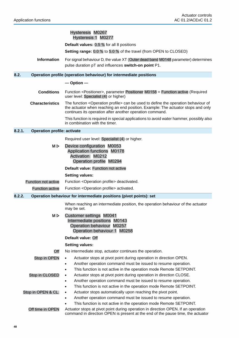
Hysteresis M0267Hysteresis 1 M0277
Default values: 0.5 % for all 8 positions
Setting range: 0.0 % to 5.0 % of the travel (from OPEN to CLOSED)
Information For signal behaviour D, the value XT (Outer dead bandM0148 parameter) determinespulse duration pT and influences switch-on point P1.
8.2. Operation profile (operation behaviour) for intermediate positions
— Option —
Conditions Function <Positioner>, parameter Positioner M0158 = Function active (Requireduser level: Specialist (4) or higher)
Characteristics The function <Operation profile> can be used to define the operation behaviour ofthe actuator when reaching an end position. Example: The actuator stops and onlycontinues its operation after another operation command.
This function is required in special applications to avoid water hammer, possibly alsoin combination with the timer.
8.2.1. Operation profile: activate
Required user level: Specialist (4) or higher.
Device configuration M0053Application functions M0178Activation M0212Operation profile M0294
Default value: Function not active
Setting values:
Function not active Function <Operation profile> deactivated.
Function active Function <Operation profile> activated.
8.2.2. Operation behaviour for intermediate positions (pivot points): set
When reaching an intermediate position, the operation behaviour of the actuatormay be set.
Customer settings M0041Intermediate positions M0143Operation behaviour M0257Operation behaviour 1 M0258
Default value: Off
Setting values:
Off No intermediate stop, actuator continues the operation.
Stop in OPEN ● Actuator stops at pivot point during operation in direction OPEN.● Another operation command must be issued to resume operation.● This function is not active in the operation mode Remote SETPOINT.
Stop in CLOSED ● Actuator stops at pivot point during operation in direction CLOSE.● Another operation command must be issued to resume operation.● This function is not active in the operation mode Remote SETPOINT.
Stop in OPEN & CL. ● Actuator stops automatically upon reaching the pivot point.● Another operation command must be issued to resume operation.● This function is not active in the operation mode Remote SETPOINT.
Off time in OPEN Actuator stops at pivot point during operation in direction OPEN. If an operationcommand in direction OPEN is present at the end of the pause time, the actuator
48
Actuator controlsApplication functions AC 01.2/ACExC 01.2

resumes operation into direction OPEN. If an operation command in direction CLOSEis present during the pause time, the pause is interrupted and operation into directionCLOSE resumed.
Off time in CLOSED When reaching the pivot point, the actuator stops during operation in direction CLOSE.If an operation command in direction CLOSE is present at the end of the pause time,the actuator resumes operation into direction CLOSE. If an operation command indirection OPEN is present during the pause time, the pause is interrupted andoperation into direction OPEN resumed.
Off time in OPEN & CL. Actuator stops automatically upon reaching the pivot point. If an operation commandin direction OPEN or CLOSE is present at the end of the pause time, the actuatorresumes operation depending on the operation command.
Information The actuator stops for each activated intermediate position, for which operation be-haviour Stop in OPEN, Stop in CLOSED or Stop in OPEN & CL. is assigned.
8.2.3. Off times for intermediate positions (pivot points): set
An off time can be defined for each pivot point.
Once a pivot point with the operation behaviour Off time in OPEN , Off time inCLOSED or Off time in OPEN & CL. is reached, the AC generates the Operationpause active indication during the off time.
Required user level: Specialist (4) or higher.
Customer settings M041Intermediate positions M0143Off times M0268Off time 1 M0285
Default values: 1 sSetting ranges: 1 to 1,800 seconds
8.3. Two-wire control
— Option —
Conditions Operation mode Remote (Selector switch = position Remote control).
Characteristics With the function <Two-wire control>, the actuator can be operated to end positionOPEN or CLOSED via a digital input.
Information In this function, the actuator only reacts to commands via the input OPEN / CLOSE.Other inputs to which the operation commands OPEN, STOP, CLOSE were assigned,do not have any function.
Execute operation commands via digital input:
Designation of digital input OPEN / CLOSE(wiring diagram designation: OPEN/CLOSE
Default setting ● Input OPEN / CLOSE = low level (0 V DC or input open):Actuator runs in direction CLOSE.
● Input OPEN / CLOSE = high level (standard: +24 V DC):Actuator runs in direction OPEN.
Configuration of digital input
For the two-wire control, a digital input for the OPEN / CLOSE signal has to beconfigured.
Required user level: Specialist (4)
Device configuration M0053I/O interface M0139Digital inputs M0116
49
Actuator controls AC 01.2/ACExC 01.2 Application functions

Example Use input DIN 5 for signal OPEN / CLOSE:
Parameter: Signal DIN 5 M0122 = OPEN/CLOSE
Information The logic for the digital inputs may be inverted. Depending on the parameter setting(e.g. Coding DIN 6 M0128), the input is either High active or Low active. Defaultsetting is High active.
8.4. Positioner (operation mode Remote SETPOINT)
— Option —
Conditions This function requires one of the following equipments within the actuator:
● Electronic control unit with MWG (Non-Intrusive version)● Potentiometer● Electronic position transmitter EWG/RWGFurther conditions for the positioner operation mode:
● Positioner enabled and activated.● Operation mode Remote (selector switch = position Remote control).
Characteristics The positioner records setpoint position E1 and actual position value E2 forcomparison. Depending on the detected deviation, the actuator motor then runs indirection OPEN or CLOSE.
Information ● If the actuator is controlled via a setpoint (e.g. 0 – 20 mA), the status indicationS0003 on the display shows both the setpoint position E1 and the actual positionvalue E2.
● If the status indication S0003 only shows the actual position value E2, OPEN- CLOSE control is active: there is no setpoint control via the positioner. In thiscase, you have to change-over to setpoint control first, refer to <Change-overbetween OPEN - CLOSE control and setpoint control> chapter.
8.4.1. Positioner: activate
Required user level: Specialist (4) or higher.
Device configuration M0053Application functions M0178Activation M0212Positioner M0158
Default value: Function not active
Setting values:
Function not active Function <Positioner> deactivated.
Function active Function <Positioner> activated.
8.4.2. Adaptive behaviour: switch on or off
Adaptive positioning may reduce the number of starts and compensate for the overrunof the actuator.
Customer settings M0041Positioner M0145Adaptive behaviour M0147
Default value: Adaptive I
Setting values:
Off Adaptive behaviour switched off.
Adaptive I Adaptive behaviour for precise positioning (high positioning accuracy).
Due to the inertia of actuator and valve, the valve position changes only slightly afterswitching off the actuator (overrun). The positioner determines the resulting error
50
Actuator controlsApplication functions AC 01.2/ACExC 01.2

between setpoint and actual value for both directions and automatically adapts theinner dead bands Xi and therefore switching point P2.
On the basis of the determined inner dead bands Xi and the set hysteresis(parameters Positioner hyst. OPEN M0598 or Positioner hyst. CLOSE M0599), theouter dead bands XT are automatically determined.
This reduces the error caused by the overrun after only a few operations and a highpositioning accuracy is achieved.
Figure 38: Positioner positioning behaviour
E1 SetpointE2 Actual valueP1 Switch-on pointP2 Switch-off point in OPEN directionP3 Setpoint reachedXT Max. error (outer dead band)
Xi1 Overrun in direction OPEN (inner dead band OPEN)
Xi2 Overrun in direction CLOSE (inner dead band CLOSE)
8.4.3. Overrun (inner dead band): set manually
The inner dead band determines the switch-off point of the actuator and thereforeinfluences the overrun.
The inner dead band may be set individually for the directions OPEN and CLOSE.
Manual setting is only possible if the adaptive behaviour, parameter Adaptivebehaviour M0147 is switched off.
Customer settings M0041Positioner M0145Dead band OPEN M0234Dead band CLOSE M0235
Default values: 0.5 % for dead band OPEN and CLOSED
Setting ranges: 0.0 – 10.0 % for dead band OPEN and CLOSED
Information ● Inner dead bands may not be set wider than outer dead bands.● Inner dead bands may not be set too narrow as this may cause unnecessary
switching procedures (premature wear) or oscillation of the actuator.
.
8.4.4. Max. error variable (outer dead band): set manually
The outer dead band determines the switching-on point of the actuator.
51
Actuator controls AC 01.2/ACExC 01.2 Application functions

The motor starts if the actual value (input signal E2) or a change in nominal value ishigher than the max. error variable determined by the outer dead band.
Manual setting is only possible if the adaptive behaviour, parameter Adaptivebehaviour M0147 switched off.
Customer settings M0041Positioner M0145Outer dead band M0148
Default value: 1.0 %Setting range: 0.1 – 10.0 %
8.4.5. Dead time: set
The dead time prevents the operation to a new setpoint position within apre-determined time.
Customer settings M0041Positioner M0145Dead time M0149
Default value: 0.5 sSetting range: 0.2 – 60.0 s (seconds)
Information It must be ensured via the controls that the max. permissible number of starts of theactuator is not exceeded. This can be achieved by setting the dead time to a suffi-ciently high value.
8.4.6. Hysteresis for positioner: set
The hysteresis determines the switching accuracy. It can be used to reduce thenumber of starts for example.
This setting can only be made if the adaptive behaviour, parameter Adaptivebehaviour M0147 is set to Adaptive I.
Customer settings M041Positioner M0145Positioner hyst. OPEN M0598Positioner hyst. CLOSE M0599
Default values: 0.5 % for OPEN and CLOSED
Setting range: 0.0 % to 5.0 % of the travel (from OPEN to CLOSED)
8.4.7. Closing fully/opening fully (end position tolerance for setpoint)
If the end positions cannot be reached due to inaccurate analogue setpoint signals(0/4 mA or 20 mA), a tolerance for the setpoint within the end position range can beset. If the tolerance is exceeded or not reached, the actuator continues the operationuntil the full end position has been reached. This ensures that the actuator opensand closes fully.
Customer settings M0041Positioner M0145Tolerance CLOSE M0150Tolerance OPEN M0151
Default values:Tolerance CLOSE = 0.0 %Tolerance OPEN = 100.0 %Setting ranges: (in percent of the travel)Tolerance CLOSE = 0.0 – 5.0 %Tolerance OPEN = 95 – 100.0 %
52
Actuator controlsApplication functions AC 01.2/ACExC 01.2

8.4.8. Setting range: limit
Travel can be limited in directions OPEN and/or CLOSE.
This prevents end position(s) OPEN and/or CLOSED from being approached inmodulating duty. The actuator stops when reaching the set limit value.
For OPEN - CLOSE control (LOCAL or REMOTE OPEN-CLOSE operation mode),this limitation is not active. The valve can then be run into the end positions eithervia the local controls or from remote.
Figure 39: Limitation of setting range
[1] Permissible actuator travel for setpoint control[2] Permissible actuator travel for OPEN - CLOSE control
Activate limitation
Customer settings M0041Positioner M0145Limit setting range M0845
Default value: Function not active
Setting values:
Function not active Limitation deactivated.
Function active Limitation activated.
Set limits
Customer settings M0041Positioner M0145Limit OPEN M0162Limit CLOSE M0161
Default values:Limit OPEN = 100.0 %Limit CLOSE = 0.0 %Setting ranges: 0.0 ... 100.0 % of travel
8.4.9. Change-over between OPEN - CLOSE control and setpoint control
For actuators equipped with a positioner, it is possible to change over between OPEN- CLOSE control (Remote OPEN-CLOSE) and setpoint control (RemoteSETPOINT).
Condition For the change-over, a digital input for the signal MODE has to be available andconfigured.
Configuration of digital input
Required user level: Specialist (4).
Device configuration M0053I/O interface M0139Digital inputs M0116
53
Actuator controls AC 01.2/ACExC 01.2 Application functions

Example Use input DIN 1 for change-over:
Parameter: Signal DIN 1 M0118Setting value: MODE (wiring diagram designation: MODE)
Information The logic for the digital inputs may be inverted. Depending on the parameter setting(e.g. Coding DIN 4 M0126), the input is either High active or Low active. Defaultsetting of MODE input is Low active.
Change-over via digital input MODE
Switching behaviour for coding Low active:
(Default factory setting)
● Input MODE = low level (0 V DC or input open) = Remote SETPOINTThe actuator reacts to a setpoint signal (e.g. 0/4 – 20 mA)
● Input MODE = high level (standard: +24 V DC) = Remote OPEN-CLOSE:The actuator reacts to operation commands OPEN, STOP, CLOSE.
8.4.10. Input of setpoint position
The setpoint position is generally led via input AIN1, but can also be led via AIN 2.
Required user level: AUMA (6).
Device configuration M0053I/O interface M0139Analogue inputs M0389Signal AIN 1 M0135Signal AIN 2 M0138
Default value AIN 1: Setpoint position
8.4.11. Input range of setpoint position
Required user level: Specialist (4) or higher.
Device configuration M0053I/O interface M0139Analogue inputs M0389Low limit AIN 1 M0133High limit AIN 1 M0134Default values:
Low limit AIN 1 = 0 mAHigh limit AIN 1 = 20 mASetting values: 0 ... 20 mA
8.4.12. Split Range operation
Requirements ● <Positioner> function must be enabled and activated:
Function In Split Range operation, a setpoint position E1 can be shared by up to threepositioners. A typical application example is a pipeline with a bypass. The actuatormounted on the bypass reacts in the lower limit (e.g. 0 – 10 mA), the actuator on themain valve in the upper limit (e.g. 10 – 20 mA). If the setpoint position is within thesetpoint range defined for the individual actuator, the actuator behaviour will beidentical to standard positioner operation. If the setpoint position is higher or lowerthan the upper or the lower limit of the setpoint range of the respective actuator, theactuator will run to positions OPEN or CLOSED.
The upper and lower limit of the respective actuator is defined via the analogue input.(<Input range of setpoint position>)
In addition, the upper and lower limit of the total target value (valid for all actuatorsgrouped in a split range operation).
54
Actuator controlsApplication functions AC 01.2/ACExC 01.2

Activate split range operation
Required user level: Specialist (4) or higher.
Device configuration M0053Application functions M0178
Activation M0212Split range operation M01650Default value: Function not active
Setting values:
Function not active <Split range operation> function deactivated.
Function active <Split range operation> function activated.
Set total target value range
The set lower limit of total target value is used as failure source for failure behaviourduring split range operation. <Failure behaviour on loss of signal>
Customer settings M0041Positioner M0145
Low limit target value M01651High limit target value M01652Default values:Low limit target value = 0.0 mAHigh limit target value = 20.0 mASetting ranges: 0.0 ... 20.0 mA
8.5. Process controller
— Option —
Requirements This function requires one of the following equipments within the actuator:
● Electronic control unit with MWG (non-intrusive version)● Potentiometer● Electronic position transmitter EWG/RWGFurther conditions for the process controller operation mode:
● Process controller enabled and activated.● Operation mode Remote (Selector switch = position Remote control).
Characteristics The following figure illustrates the function of the process controller:
The process controller [2] receives the process setpoint E7 and the actual processvalue E4 (e.g. from a sensor). On the basis of both values, the process controllercalculates the position setpoint E1 for positioner [3]. In turn, the positioner [3]compares this target setpoint with the actual position value E2 of the valve and issuesthe operation commands (OPEN - CLOSE) for the actuator.
55
Actuator controls AC 01.2/ACExC 01.2 Application functions

Figure 40: Process controller function
[1] AC actuator controls[2] Process controller[3] Positioner[4] Actuator[5] Position transmitter e.g. EWG/RWG/MWG[6] Sensor[7] ValveE1 Position setpoint (internal)E2 Actual position valueE4 Actual process valueE7 Process setpoint
Application The process controller can be used to control pressure, flow or flow rates, flow levelsand temperature.
8.5.1. Process controller activation
Required user level: Specialist (4) or higher.
Device configuration M0053Application functions M0178Activation M0212Process controller M0741
Default value: Function not active
Setting values:
Function not active <Process controller> function deactivated.
Function active <Process controller> function activated.
8.5.2. Process controller: set modulating behaviour
Three controller types are available to ideally adapt the modulating behaviour of theprocess controller to the respective application.
56
Actuator controlsApplication functions AC 01.2/ACExC 01.2

Customer settings M0041Process controller M0742Modulating behaviour M0887
Default value: PI controller
Setting values:
P controller P controller immediately reacts to a control deviation (i.e. actively) and amplifies theinput signal (error variable) proportionally to the set amplification. Setting parameter:Proport. gain Kp M0744
Figure 41: Step response of P controller
P controller application For uncritical closed-loop applications allowing to accept continuous error variablesin the event of failures, e.g. pressure, flow, filling level and temperature control.
PI controller PI controllers consist of a P fraction immediately reacting to a control deviation andan I fraction for chronological integration of the input signal (error variable). Due tothe additional time constant of the I fraction, the output value takes more time toreach the target status (i.e. inertia of control loop response) whereas positioningaccuracy increases at the same time (lower control deviation). Parameters for settingthe time constant: Reset time Ti M0745
Figure 42: Step response of PI controller
PI controller application Quick control circuits not allowing continuous error variables, e.g. pressure,temperature and ratio control.
PID controller Compared to the PI controller, the PID controller has an additional D fractionaccounting for changes in the error variable (change rate). The D fraction quicklyreacts to changes, even to minor control deviations with large output values.Parameter for setting the D fraction: Rate time Td M0746
Figure 43: Step response of PID controller
PID controller use For precise and highly dynamic control not allowing a continuous error variable.
8.5.3. Setpoint source (input for process setpoint)
Customer settings M0041Process controller M0742
57
Actuator controls AC 01.2/ACExC 01.2 Application functions

Setpoint source M0743Default value: I/O interface
Setting values:
I/O interface The process setpoint is defined via an analogue input (AIN 1 or AIN 2) of the I/Ointerface.
Internal setpoint The process setpoint is generated internally via actuator controls: parameters Internalsetpoint 1 M0749 / Internal setpoint 2 M0750
Information To use internal setpoint 2, a digital input must be configured accordingly.
8.5.4. Behaviour on loss of process setpoint
Customer settings M0041Process controller M0742Beh. setpoint failure M0747
Default value: Internal setpoint 1
Setting values:
Internal setpoint 1 In case of process setpoint signal loss, the actuator controls switch to the internalsetpoint 1. Parameter Internal setpoint 1 M0749
Internal setpoint 2 In case of process setpoint signal loss, the actuator controls switch to the internalsetpoint 2. Parameter Internal setpoint 2 M0750
Failure behaviour In case of process setpoint signal loss, failure behaviour procedure is activated.Parameter Failure behaviour M0378
Last setpoint In case of process setpoint signal loss, the last available process setpoint will stillbe used as setpoint.
8.5.5. Inverse operation
As standard, the valve is opened by the modulating actuator as soon as the actualprocess value falls below the process setpoint. Depending on the process, it may,however, be necessary that the valve closes as soon as the actual process valuefalls below the process setpoint. In this case, the respective parameters are used toset the process controller to inverse operation.
Customer settings M0041Process controller M0742Inverse operation M0748
Default value: Function not active
Setting values:
Function not active Inverse operation is deactivated.
Function active Inverse operation is activated.
8.5.6. Internal process setpoint
An internal process setpoint may be set with this parameter. The internal processsetpoint is used if:
● Parameter Setpoint source M0743 is set to Internal setpoint or● Parameter Beh. setpoint failure M0747 is set to Internal setpoint 1 or Internal
setpoint 2.
Customer settings M0041Process controller M0742Internal setpoint 1 M0749Internal setpoint 2 M0750
Default value: 50.0 %Setting range: 0.0 ... 100.0 %
58
Actuator controlsApplication functions AC 01.2/ACExC 01.2

8.5.7. Setting procedure
The setting of the process controller largely depends on the area of controllerapplication. A PI controller suffices for most applications.
Procedure 1. Operate the controller as PT controller, i.e. set the parameters as follows:- Proportional gain Kp = 1- Reset time Ti = 1,000 s- Rate time Td = 0
2. Double proportional gain Kp until the control loop starts to oscillate.3. Reduce proportional gain Kp to 60 % of the set value.4. Decrease reset time Ti until the error variable equals zero.
8.5.8. Proportional amplification Kp: set
In the event of an error variable, the P portion immediately (i.e. actively) changesthe position value proportionally to the error variable.
If a small error variable already requires a major valve position adjustment, theproportional gain Kp must be increased.
Information If the reaction is too extreme (overshoot), the value must be reduced. If the reactionis too weak, the value must be increased.
Customer settings M0041Process controller M0742Proport. gain Kp M0744
Default value: 1.0Setting range: 0.1 ... 10.0
8.5.9. Reset time Ti: set
The reset time determines the I portion of the controller. The more inert a system,the higher this value should be set.
Information ● Increase Ti in case of propensity for oscillation.● Decrease Ti if the reactions are excessively delayed.● Starting value for fast processes (e.g. pressure): 10 s● Starting value for slow processes (e.g. temperature): 1000 s
Customer settings M0041Process controller M0742Reset time Ti M0745
Default value: 1,000 s (seconds)
Setting range: 1 ... 1000 s
8.5.10. Rate time Td: set
The rate time determines the D portion of the controller. Typically, no setting isrequired here (= 0), since actuator and valve – due to the operating time – cannotreact abruptly to a sudden occurrence of an error variable.
Information ● Increase Td in case of propensity for oscillation.● Initial value for actuators: 0 s
Customer settings M0041Process controller M0742Rate time Td M0746
Default value: 0 s (seconds)
Setting range: 1 ... 100 s
59
Actuator controls AC 01.2/ACExC 01.2 Application functions

8.5.11. Actual value source (input for actual process value)
Customer settings M0041Process controller M0742Actual value source M0756
Default value: I/O interface
Setting values:
I/O interface The actual process value is defined via an analogue input (AIN 1 or AIN 2) of theI/O Interface.
8.6. Stepping mode
— Option —
Conditions This function requires one of the following equipments within the actuator:
● MWG (Non-Intrusive version)● Potentiometer● Electronic position transmitter EWG/RWG
Characteristics ● With stepping mode, the operating time can be increased for the entire or anyportion of the valve travel.
● Stepping mode can be individually activated for the directions OPEN andCLOSE.
Figure 44: Stepping mode
[1] Stepping range OPEN[2] Stepping range CLOSEP1 Start of stepping modeP2 End of stepping modet1 Operating time for normal operationt2 Operating time for stepping modet3 Running timet4 Off time
8.6.1. Stepping mode: activate
Stepping mode can be individually activated for the directions OPEN and CLOSE.
Required user level: Specialist (4) or higher.
60
Actuator controlsApplication functions AC 01.2/ACExC 01.2

Device configuration M0053Application functions M0178Activation M0212Timer CLOSE M0156Timer OPEN M0206
Default value: Function not active
Setting values:
Function not active Function <Stepping mode> deactivated.
Function active Function <Stepping mode> activated.
8.6.2. Operation mode for stepping mode
Stepping mode can be activated via operation modes Local and/or Remote.
Customer settings M0041Timer M0142Step mode CLOSE M0157Step mode OPEN M0207
Default value: Off both directions
Setting values:
Off Stepping mode is switched off.
Remote Stepping mode is active in the operation modes: Remote, Remote II, Fieldbus
Local Stepping mode is active in the operation modes: Local, Service
Remote and local Stepping mode is active in the operation modes:Remote, Remote II, Fieldbus, Local,Service
Information The timer cannot be by-passed in <Operation mode EMERGENCY>.
8.6.3. Start and end of stepping mode
Start and end of stepping mode can be individually set for both directions.
Customer settings M0041Timer M0142End stepping CLOSE M0152Start stepping CLOSE M0153Start stepping OPEN M0154End stepping OPEN M0155
Default values:End stepping CLOSE = 0.0 %Start stepping CLOSE = 100.0 %Start stepping OPEN = 0.0 %End stepping OPEN = 100.0 %Setting ranges:End stepping CLOSE = 0.0 – 99.9 %Start stepping CLOSE = 0.1 – 100.0 %Start stepping OPEN = 0.0 – 99.9 %End stepping OPEN = 0.1 – 100.0 %
8.6.4. On times and off times
On or off times can be set individually for directions OPEN and CLOSE.
Customer settings M0041Timer M0142On time CLOSE M0163Off time CLOSE M0164
61
Actuator controls AC 01.2/ACExC 01.2 Application functions

On time OPEN M0165Off time OPEN M0166
Default values: 5.0 s (for all on and off times)
Setting ranges: 1 ... 1,800 s (for all on and off times)
8.7. By-pass function
— Option —
Application The by-pass function is used, e.g. for district heating pipelines. Under high pipelinepressure, the gate valve of the main valve cannot be used, pressure compensationvia by-pass valve is therefore required.
Function Two MOVs – one main valve and a by-pass valve – are linked via enable signalsBypass Sync In and By-pass Sync Out. Operation commands can only be executedif one of the two actuators sends the enable signal to the other. Release dependson the end position. This ensures that only the following operation commands maybe executed:
● The main valve can only be operated in directions OPEN or CLOSE if the by-pass valve is in end position OPEN.
● The by-pass valve can only be operated in direction CLOSE if the main valveis in end position CLOSED. However, it can always be operated in directionOPEN.
Figure 45: Function
Table 7: Main valve reaction to by-pass valve position.
Main valveBy-pass valveRelease(available operation com-mands)
Sends enable signalBypass Sync OUT
Position
in directions OPEN andCLOSE
High level(Default: +24 V DC
End position OPEN
No operation possible1)Low level(0 V DC or input open-circuit):
other position than end posi-tion OPEN
In case of an operation command, the "Interlock by-pass" signal is sent (no release).1)
62
Actuator controlsApplication functions AC 01.2/ACExC 01.2

Table 8: By-pass valve reactions to main valve position
By-pass valveMain valveRelease(available operation com-mands)
Sends enable signalBypass Sync OUT
Position
in directions OPEN or CLOSEHigh level(Standard: +24 V DC)
End position CLOSED
in direction OPEN only1)Low level(0 V DC or input open-circuit):
Other position than end posi-tion CLOSED
In case of an operation command in direction CLOSE, the "Interlock by-pass" signal is sent (no re-lease).
1)
EMERGENCY behaviour The emergency behaviour of the by-pass function has the same characteristics asthe <EMERGENCY behaviour> function with the following differences:
In an EMERGENCY situation, both controls receive the EMERGENCY signal at thesame time. This signal starts the EMERGENCY operation specially defined for theby-pass function. (Parameter EMCY operation M0204 is therefore not available inthe <EMERGENCY behaviour> function).
EMERGENCY operation procedure
1. By-pass valve is opened first.2. Once the by-pass valve is fully opened, the main valve is closed.3. Once the main valve is fully closed, the by-pass valve is fully opened.
Configuration of digital inputs
Required user level: Specialist (4) or higher.
Device configuration M0053I/O interface M0139Digital inputs M0116
Example Use input DIN4 for signal Bypass Sync In:
Use input DIN6 for signal EMERGENCY:
Setting values:
● Signal DIN 5 M0122 = By-pass Sync In(wiring diagram designation: BYPASS SYNC IN)
● Signal DIN 6 M0121 = EMERGENCY(wiring diagram designation: NOT/EMERGENCY)
Information The logic for the digital inputs may be inverted. Depending on the parameter setting(e.g. Coding DIN 6 M0128), the input is either High active or Low active. Defaultsetting is High active.
Configuration of digital output
Required user level: Specialist (4) or higher.
Device configuration M0053I/O interface M0139Digital outputs M0110
Example Use output DOUT6 for signal Bypass Sync Out:Parameter: Signal DOUT 6 M0111Setting value: Bypass Sync Out (wiring diagram designation: BYPASS SYNCOUT)
8.7.1. Bypass function: activate
Required user level: Specialist (4) or higher.
63
Actuator controls AC 01.2/ACExC 01.2 Application functions
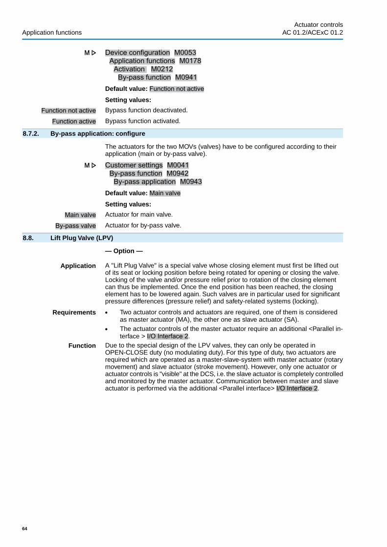
Device configuration M0053Application functions M0178Activation M0212By-pass function M0941
Default value: Function not active
Setting values:
Function not active Bypass function deactivated.
Function active Bypass function activated.
8.7.2. By-pass application: configure
The actuators for the two MOVs (valves) have to be configured according to theirapplication (main or by-pass valve).
Customer settings M0041By-pass function M0942By-pass application M0943
Default value: Main valve
Setting values:
Main valve Actuator for main valve.
By-pass valve Actuator for by-pass valve.
8.8. Lift Plug Valve (LPV)
— Option —
Application A "Lift Plug Valve" is a special valve whose closing element must first be lifted outof its seat or locking position before being rotated for opening or closing the valve.Locking of the valve and/or pressure relief prior to rotation of the closing elementcan thus be implemented. Once the end position has been reached, the closingelement has to be lowered again. Such valves are in particular used for significantpressure differences (pressure relief) and safety-related systems (locking).
Requirements ● Two actuator controls and actuators are required, one of them is consideredas master actuator (MA), the other one as slave actuator (SA).
● The actuator controls of the master actuator require an additional <Parallel in-terface > I/O Interface 2.
Function Due to the special design of the LPV valves, they can only be operated inOPEN-CLOSE duty (no modulating duty). For this type of duty, two actuators arerequired which are operated as a master-slave-system with master actuator (rotarymovement) and slave actuator (stroke movement). However, only one actuator oractuator controls is "visible" at the DCS, i.e. the slave actuator is completely controlledand monitored by the master actuator. Communication between master and slaveactuator is performed via the additional <Parallel interface> I/O Interface 2.
64
Actuator controlsApplication functions AC 01.2/ACExC 01.2

Figure 46: Schematic representation of the function of a Lift Plug Valve
The master actuator may generally only be operated in direction OPEN or CLOSEif the slave actuator is fully opened. This is ensured by a signal of the slave actuatorto the digital LPV Sync In input of the master actuator as soon as the slave actuatorhas reached end position OPEN.The slave actuator may generally only be operatedin direction CLOSE if the master actuator is in end position OPEN or CLOSED. Thisis ensured by a corresponding signal of the master actuator to the digital LPV SyncIn input of the slave actuator. However, it can always be operated in direction OPEN.
If the master actuator receives an operation command for direction OPEN or CLOSE,it will first send a command to the slave actuator for operation in direction OPEN.Once the slave actuator has reached end position OPEN and sends the feedbacksignal, the master actuator executes the requested operation command itself. Afterreaching the desired end position, it will request the slave actuator to run to endposition CLOSED.
Figure 47: Schematic representation of signals and operation commands betweenmaster and slave actuator as well as signals of the master actuator to the DCS
Example of digital input configuration
Required user level: Specialist (4)
Device configuration M0053I/O interface M0139Digital inputs M0116
Master actuator (MA) Use input DIN 7 for signal LPV system ok,
65
Actuator controls AC 01.2/ACExC 01.2 Application functions

Use input DIN 8 for signal LPV end position CL,
Use input DIN 9 for signal LPV Sync In,
Use input DIN 10 for signal LPV sel.sw.Remote:
Setting values:
Signal DIN 7 M0383 = LPV system ok (SA)Signal DIN 8 M0390 = LPV end position CLOSED (SA)Signal DIN 9 M0391 = LPV Sync InSignal DIN 10 M0392 = LPV sel. sw. REM (SA)
Slave actuator (SA) Use input DIN 1 for signal LPV Sync In,
Use input DIN 2 for signal (Run) CLOSE,
Use input DIN 3 for signal (Run) OPEN,
Setting values:
Signal DIN 1 M0117 = LPV Sync InSignal DIN 2 M0120 = CLOSESignal DIN 3 M0119 = OPEN
Information The logic for the digital inputs may be inverted. Depending on the parameter setting(e.g. Coding DIN 7 M0393), the input is either High active or Low active. Defaultsetting is High active.
Example of digital output configuration
Required user level: Specialist (4)
Device configuration M0053I/O interface M0139Digital outputs M0110
Master actuator (MA) Only the outputs used for control of the slave actuator are listed, the outputs to theDCS are preset as standard (e.g.End position CLOSED, End position OPEN, Selectorsw. REMOTE, Failure (Cfg))Use output DOUT 8 for signal LPV SA-CLOSE,
Use output DOUT 9 for signal LPV SA-OPEN,
Use output DOUT 10 for signal LPV Sync Out,
Setting values:
Signal DOUT 8 M0398 = LPV run CLOSE (SA)Signal DOUT 9 M0399 = LPV run OPEN (SA)Signal DOUT 10 M0400 = LPV Sync Out
Slave actuator (SA) Use output DOUT 1 for signal System ok,
Use output DOUT 2 for signal End position CLOSED,
Use output DOUT 3 for signal LPV Sync Out,Use output DOUT 4 for signal Selector sw. REMOTE,
Setting values:
Signal DOUT 1 M0109 = System okSignal DOUT 2 M0115 = End position CLOSEDSignal DOUT 3 M0114 = LPV Sync OutSignal DOUT 4 M0113 = Selector sw. REMOTE
Information The logic for the digital outputs may be inverted. Depending on the parameter setting(e.g. Coding DOUT 1 M0102), the input is either High active or Low active. Defaultsetting is High active.
66
Actuator controlsApplication functions AC 01.2/ACExC 01.2

8.8.1. LPV function: activate
Required user level: Specialist (4) or higher.
Device configuration M0053Application functions M0178Activation M0212LPV function M1087
Default value: Function not active
Setting values:
Function not active Function deactivated.
Function active Function activated.
8.8.2. LPV actuator type: configure
Required user level: Specialist (4) or higher.
When using the LPV function, it must be defined for each actuator controls whetherit controls the master or the slave actuator.
Customer settings M0041Lift Plug Valve M1089LPV application M1090
Default value: MA master actu./rotat.
Setting values:
MA master actu./rotat. Actuator controls/actuator act as master actuator is in charge of the rotation of theclosing element.
SA slave act./stroke Actuator controls/actuator act as slave actuator is in charge of the stroke of theclosing element.
8.8.3. Delay time of master LPV actuator: configure
Configure delay time for operation in direction OPEN
A delay time for operation in direction OPEN can be defined in end position CLOSEDof the master actuator. When reaching end position OPEN of the slave actuator, theprocedure for opening valve will be delayed by this time. The master actuator willthen run in direction OPEN.
Required user level: Specialist (4) or higher.
Customer settings M0041Lift Plug Valve M1089Delay MA direct.OPEN M1091
Default value: 02:00.0Setting ranges: 00:00,0 ... 15:00.0 min:s (minutes:seconds)
Configure delay time for operation in direction CLOSE
A delay time for operation in direction CLOSE can be defined in end position OPENof the master actuator. When reaching end position OPEN of the slave actuator, theprocedure for closing valve will be delayed by this time.The master actuator will thenrun in direction CLOSE.
Required user level: Specialist (4) or higher.
Customer settings M0041Lift Plug Valve M1089Delay MA direct.CLOSE M1092
Default value: 00:00.0Setting ranges: 00:00.0 15:00.0 min:s (minutes:seconds)
67
Actuator controls AC 01.2/ACExC 01.2 Application functions

8.8.4. Delay time of slave LPV actuator: configure
A delay time for operation in direction CLOSE of the slave actuator can be definedin end positions OPEN and CLOSED of the master actuator. When reaching endpositions OPEN or CLOSED of the master actuator, the procedure for opening orclosing valve will be delayed by this time.The slave actuator will then run in directionCLOSE.
Required user level: Specialist (4) or higher.
Customer settings M0041Lift Plug Valve M1089Delay SA direct.CLOSE M1093
Default value: 00:00,0Setting ranges: 00:00.0 ... 15:00.0 min:s (minutes:seconds)
8.9. Multiport valve function (operation to position)
— Option —
Application For valves not equipped with end stops (multi-turn) and with up to 12 ports (multiportvalves)
Characteristics The multiport valve function allows to directly access a valve port (position) of a valveequipped with up to 12 ports without stopping at any other port (position). Example:Operation from position 2 to 4 without stopping at position 3.
In the operation mode Local, the set position are approached as directly as possible,i.e. the direction of rotation (clockwise or counterclockwise) depends on the currentposition of the valve.
In operation mode Remote, up to 10 positions can either be approached with adefined direction of rotation (counterclockwise or clockwise) or as directly as possible.The actuator then operates the valve with the defined direction of rotation or asdirectly as possible to the defined valve attachment, irrespective of the actuatorposition.
Information ● The multiport valve function is only permissible in combination with an AUMAactuator and an AUMA gearbox.
● The output speed at the output drive (of the gearbox) or the valve should notexceed approx. 0.3 rpm; otherwise positioning accuracy will decrease.
Procedure for commissioning a multiport valve
1. Set/check multiport valve parameters:(generally, they are set in the factory prior to delivery)- Actuator type- Gear reduction ratio- Number of ports (positions)- Configuration of digital inputs
2. Define/check positions (of valve ports).3. Set/check signal behaviour of positions.4. Set home port (zero position).5. Approach positions.6. If required, perform/correct multiport valve parameter settings like inertia, dead
band, backlash compensation and hysteresis.
8.9.1. Multiport valve function: activate
Required user level: Specialist (4) or higher.
Device configuration M0053Application functions M0178
68
Actuator controlsApplication functions AC 01.2/ACExC 01.2

Activation M0212MPV function M1139
Default value: Function not active
Setting values:
Function not active Function deactivated.
Function active Function activated.
8.9.2. Actuator type: set/check
The actuator type is set in the factory but can be modified at a later date.
Required user level: Specialist (4) or higher.
Customer settings M0041Multiport valve M1140Actuator type M1142
Default value: Actuator type set in the factory
Setting ranges: Selection list of all AUMA actuators
8.9.3. Gear reduction ratio: set/check
The reduction ratio of the gear stage of the actuator mounted to the valve gearboxmust be set here. To facilitate adjustment, a selection table of supported gearboxesis available.
Required user level: Specialist (4) or higher.
Customer settings M0041Multiport valve M1140Reduction ratio M1143
Default values: GS50.3
Setting values:
Table 9: Selection of gearboxes supported by AUMA
Sizes GS160.3 – GS 250.3Sizes GS 50.3 – GS 125.3GS160.3GS50.3GS160.3/GZ160.3(4:1)GS63.3GS160.3/GZ160.3(8:1)GS80.3GS200.3GS100.3GS200.3/GZ200.3(4:1)GS100.3/VZ2.3GS200.3/GZ200.3(8:1)GS100.3/VZ3.3GS250.3GS100.3/VZ4.3GS250.3/GZ250.3(4:1)GS125.3GS250.3/GZ250.3(8:1)GS125.3/VZ2.3
GS125.3/VZ3.3GS125.3/VZ4.3
8.9.4. Number of ports (positions)
Number of valve ports (positions)
Required user level: Specialist (4) or higher.
Customer settings M0041Multiport valve M1140Number of ports M1141
Default value: 8Setting range: 0 to 12
69
Actuator controls AC 01.2/ACExC 01.2 Application functions

8.9.5. Home port (zero position): set
The home port is the zero position (0° or 360° of one turn) and is consequently thestarting point for all other intermediate positions.
Information Set the gear reduction ratio (parameter Reduction ratio M1143) and the actuatortype (parameter Actuator type M1142) prior to setting the home port.
Set home port 1. Position multiport valve to zero position either via manual operation (handweel)or via motor operation (via push buttons of local controls)
2. In a next step, confirm this position (with Yes) as home port via parameter MPVhome port M1162.As an alternative, the home port position can also be confirmed via a signal ata digital input. To this end, a digital input has to be available and configured.
Set home port (zero position) via parameter
Required user level: Specialist (4) or higher.
Customer settings M0041Multiport valve M1140MPV home port M1162Set?
Configuration of digital input
Required user level: Specialist (4).
Device configuration M0053I/O interface M0139
Digital inputs M0116Example Use input DIN 5 for “Set home port” signal:
Parameter: Signal DIN 5 M0122Setting value: MPV set home pos. (wiring diagram designation: Home port)
Information The logic for the digital inputs may be inverted. Depending on the parameter setting(e.g. Coding DIN 5 M0127), the input is either High active or Low active. Defaultsetting is High active.
8.9.6. Positions (of valve ports): define/check
Each position can be set to any value between 0° and 360° (one full turn of the valve).
Information Prior to setting the positions, the home port must be defined (MPV home port para-meter).
This corresponds to the zero position of the valve (0° or 360° of one full valve turnas well as 0 % or 100 % of position feedback).
The positions of the valve ports have to be set afterwards.
Customer settings M0041Multiport valve M1140MPV positions M1149
Setting ranges: 0.0 to 360.0°
Default values: 0.0° (for all positions)
If desired, positions can be preset in the factory.
Example configuration for a multiport valve comprising 8 ports: All 8 positions areevenly spread across 360°.
Position 1 = 0.0 (or 360°)Position 2 = 45.0
70
Actuator controlsApplication functions AC 01.2/ACExC 01.2

Position 3 = 90.0Position 4 = 135.0Position 5 = 180.0Position 6 = 225.0Position 7 = 270.0Position 8 = 315.0
8.9.7. Operate to position via push buttons of the local controls
To operate to a position via push buttons of the local controls, status indication S0017must be shown (refer to <Indications in the display>).
Figure 48: Status indication of multiport valve (selector switch in position OFF)
Operation in clockwise or counterclockwise direction:
When changing the selector switch to position Local control (LOCAL), the displaychanges:
Figure 49: Status indication of multiport valve (selector switch in position LOCAL)
As a consequence, the valve can be operated into clockwise or counterclockwisedirection (display shows CW or CCW)
Direct operation to a position:
When selector switch is in position 0 (OFF), the function "Direct operation to a positionvia push buttons" is activated via Details (push button ) (display shows Esc).
Figure 50: Status indication of multiport valve (selector switch in position OFF)
When changing the selector switch to position Local control (LOCAL), the displaychanges for selection of the desired position:
Figure 51: Status indication of multiport valve (selector switch in position LOCAL)
Select the desired position (P1, P2, ...) via push buttons and confirm selectionvia Ok (push button ).
→ The operation is issued as soon as push button Ok is pressed.
71
Actuator controls AC 01.2/ACExC 01.2 Application functions

SymbolSet positions (of valve ports)
(P1, P2, ...) selected position (1, 2, ...)P
No position has been selected.– – / –N/A–
Actual position valueE2
To interrupt an operation (triggered operation command):
→ Select "– – / –N/A–" during operation, and confirm via Ok (push button ). Theactuator stops in its current position.
8.9.8. Operate to position from Remote
For direct operation to position from remote, make sure that selector switch positionRemote control (REMOTE) is selected.
Operation to position via digital inputs
An input (DIN) must be configured for each position (valve port).
Configuration of digital inputs
Required user level: Specialist (4) or higher.
Device configuration M0053I/O interface M0139Digital inputs M0116
Example DIN4 input to operate to position 1 selecting the shortest path:
Parameter: Signal DIN 4 M0118 = Intermediate pos. 1
Operation behaviour for input controlSetting values for digital inputs (DIN)Operation to defined position while selecting theshortest path
Intermediate pos. 1 toIntermediate pos. 12
Operation to defined position in clockwise directionMPV: CW Position 1 toMPV: CW Position 10
Operation to defined position in counterclockwisedirection
MPV: CCW Position 1 toMPV: CCW Position 10
Actuator operation in clockwise direction (withoutstop at any position)
MPV DriveCW
Actuator operation in counterclockwise direction(without stop at any position)
MPV DriveCCW
8.9.9. Dead band
The dead band prevents operation to a new setpoint position within a specified band.
Required user level: Specialist (4) or higher.
Customer settings M0041Multiport valve M1140Reduction ratio M1143
Default value: 0.00°Setting range: 0.00 – 36.0° (degrees)
8.9.10. Backlash compensation
Adjustable backlash compensation of the overall system including valve coupling.
Required user level: Specialist (4) or higher.
Customer settings M0041Multiport valve M1140Backlash comp. M1146
Default value: 0.00°
72
Actuator controlsApplication functions AC 01.2/ACExC 01.2

Setting range: 0.00 – 36.0° (degrees)
8.9.11. Signalling behaviour of positions: set/check
Reaching of a point (valve port) can be signalled:
● via indication lights (LEDs) of the local controls or(refer to chapters <Indications> <Indication lights>)
● via output contacts(refer to chapters <Indications> <Assignment of outputs>)
Signal behaviour, this means the signal behaviour upon reaching a position, is setvia parameter Signal behaviour.
Customer settings M0041Multiport valve M1140Signal behaviour M1147
Default value: No signal
Setting values:
No signal A: Signal behaviour Off. Position is not signalled.
C________|¯¯¯¯¯¯¯¯O B: Signal is active from reaching the position up to 360°.
C¯¯¯¯¯¯¯¯¯|_______O C: Signal is active from 0° until the position is reached.
C_______|¯|_______O D: When passing the position, a pulse signal is issued. The pulse range (range +/–around the pivot point) depends on the set hysteresis.
Figure 52: Signal behaviour of positions
Information The set signal behaviour is valid for all positions.
8.9.12. Hysteresis for signalling intermediate positions: set
The hysteresis determines the tripping point.
Example Parameter Position 4 M1153 is set to 180° (50 % of the travel).
Parameter Hysteresis M1148 is set to 3.0°.
73
Actuator controls AC 01.2/ACExC 01.2 Application functions

Figure 53: Switching behaviour for signalling behaviours B, C, D and hysteresis 3.0°.
P1 Switch-on point (●)P2 Switch-off point (○)pT Pulse duration = 2 times XT + hysteresis
Required user level: AUMA (6).
Customer settings M0041Multiport valve M1140Hysteresis M1148
Default values: 0.5° for all 10 intermediate positions
Setting range: 0.0° to 5.0° (degree)
8.10. Automatic deblocking
— Option —
Requirements This function requires one of the following equipments within the actuator:
● MWG (Non-Intrusive version)● Electronic position transmitter EWG/RWGThis function CANNOT be combined with the functions listed below:
● Lift Plug Valve● By-pass function● Operation profile● If the setting range was limited for the positioner (parameter Limit setting range
M0845 = Function active)For actuator controls in SIL version, we DISADVISE using the automatic deblockingfunction.
Unexpected starting of actuator!
When using automatic deblocking with level-controlled operation command evaluation,unexpected starting of actuator into the wrong direction might occur when trying toeliminate a double-sided torque fault (torque faults in directions OPEN and CLOSEare present at the same time).
→ Use automatic deblocking only in combination with edge controlled operationcommand evaluation (parameter Com. eval. REMOTE M1709).
Characteristics In case of torque switch tripping in intermediate position (i.e. prior to reaching theend position), the actuator automatically attempts to reach the end position byoperation into the opposite direction and executing the actual operation commandonce again.
74
Actuator controlsApplication functions AC 01.2/ACExC 01.2

The torque fault signal is suppressed during automatic deblocking. Should torqueswitching trip again once automatic deblocking is complete, the actuator is switchedoff and AC controls signal a torque fault.
8.10.1. Automatic deblocking function: activate
Required user level: Specialist (4) or higher.
Device configuration M0053Application functions M0178
Activation M0212MPV function M1679Default value: Function not active
Setting values:
Function not active Function deactivated.
Function active Function activated.
8.10.2. Operation time for operation in opposite direction: set
The actuator controls remember the first seating position and operates the actuatorfor the set operation time into opposite direction.
Required user level: Specialist (4) or higher.
Customer settings M0041Automatic deblocking M1680
Oper. time opposite M1681Default value: 3 sSetting ranges: 1 ... 60 s (seconds)
8.10.3. Number of deblocking attempts: set
Required user level: Specialist (4) or higher.
Customer settings M0041Automatic deblocking M1680
Deblocking attempts M1682Default value: 3Setting ranges: 1 ... 5
8.10.4. Tolerance range: set
Tolerance range (+/-) for original torque seating position, within which a torque faultwill be signalled after unsuccessful automatic deblocking.
Required user level: Specialist (4) or higher.
Customer settings M0041Automatic deblocking M1680
Tolerance range M1683Default value: 10 %Setting ranges: 5 ... 30 % (percentage of operating time into opposite direction)
8.11. Heater system and heaters
Possible components:
● Heater system within the actuator controls● Heaters within the actuator:
- Control unit heater in switch compartment- Motor heater (within motor housing)
75
Actuator controls AC 01.2/ACExC 01.2 Application functions
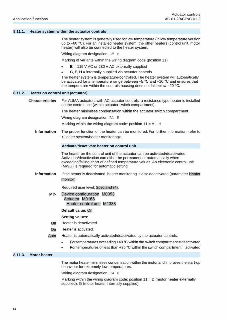
8.11.1. Heater system within the actuator controls
The heater system is generally used for low temperature (in low temperature versionup to –60 °C). For an installed heater system, the other heaters (control unit, motorheater) will also be connected to the heater system.
Wiring diagram designation: R5 H
Marking of variants within the wiring diagram code (position 11)
● B = 115 V AC or 230 V AC externally supplied● C, E, H = internally supplied via actuator controlsThe heater system is temperature-controlled. The heater system will automaticallybe activated for a temperature range between –5 °C and –10 °C and ensures thatthe temperature within the controls housing does not fall below –20 °C.
8.11.2. Heater on control unit (actuator)
Characteristics For AUMA actuators with AC actuator controls, a resistance type heater is installedon the control unit (within actuator switch compartment).
The heater minimises condensation within the actuator switch compartment.
Wiring diagram designation: R1 H
Marking within the wiring diagram code: position 11 = A – H
Information The proper function of the heater can be monitored. For further information, refer to<Heater system/heater monitoring>.
Activate/deactivate heater on control unit
The heater on the control unit of the actuator can be activated/deactivated.Activation/deactivation can either be permanent or automatically whenexceeding/falling short of defined temperature values. An electronic control unit(MWG) is required for automatic setting.
Information If the heater is deactivated, heater monitoring is also deactivated (parameter Heatermonitor)!
Required user level: Specialist (4).
Device configuration M0053Actuator M0168Heater control unit M1338
Default value: On
Setting values:
Off Heater is deactivated.
On Heater is activated.
Auto Heater is automatically activated/deactivated by the actuator controls:
● For temperatures exceeding +40 °C within the switch compartment = deactivated● For temperatures of less than +35 °C within the switch compartment = activated
8.11.3. Motor heater
The motor heater minimises condensation within the motor and improves the start-upbehaviour for extremely low temperatures.
Wiring diagram designation: R4 H
Marking within the wiring diagram code: position 11 = D (motor heater externallysupplied), G (motor heater internally supplied)
76
Actuator controlsApplication functions AC 01.2/ACExC 01.2

9. Failure functions
Definition Failure functions are started by certain events and lead to a defined action of thecontrols or the actuator. A failure operation can be started by a manual action (e.g.pressing an EMERGENCY stop button). In general, a failure operation is automaticallystarted by a fault signal from a monitoring function (e.g. loss of signal).
9.1. Reversing prevention time
Application Prevention of impermissible operation states such as: Operation command in directionOPEN, actuator still runs in direction CLOSE due to the delay time.
Characteristics The reversing prevention time (off-time between two operation commands in oppositedirection) prevents a restart for a defined interval once the motor has switched off.
Parameters and instructions for setting
Required user level: AUMA (6).
Device configuration M0053Switchgear M0173Revers. prevent. time M0174
Default value: 0.3 s seconds
Setting range: 0.1 … 30.0 s seconds
9.2. Failure behaviour on loss of signal
Characteristics The failure behaviour can be used to define AC reaction to loss of signal or a defectivesignal.
Only in operation mode Remote will the failure behaviour react to a signal loss. Inoperation modes Local or Off, there will be no reaction.
9.2.1. Failure behaviour initiation on loss of signal
Required user level: Specialist (4) or higher.
Customer settings M0041Failure behaviour M0378Signal loss beh. M0379
Default value: Good signal first
Setting values:
Good signal first The <Failure behaviour> is only initiated if the monitored signal fails (falling edge).
This setting ensures that if the signal is missing, the actuator will not start whenswitching on (Good signal first).
Immediately active The <Failure behaviour> is immediately initiated if the monitored signal is missing(is not present).
For the setting Immediately active:
The actuator can start immediately when switching on!
Risk of personal injuries or damage to the valve.
→ Ensure that the signal set under parameter Failure beh. source M0385 is presentwhen switching on.
→ Should the actuator start unexpectedly: Immediately set selector switch to pos-ition Local control (LOCAL) or 0 (OFF).
9.2.2. Failure source (failure reason) for a failure operation: set
Customer settings M0041Failure behaviour M0378Failure beh. source M0385
77
Actuator controls AC 01.2/ACExC 01.2 Failure functions

Default value: I/O interface
Setting values:
I/O interface The failure behaviour is initiated in case of loss of setpoints.
The monitoring depends on the preset setpoint range, e.g.:
● Setpoint = 4 – 20 mA, E1 lower than 3.7 mA = loss of signal● Setpoint = 10 – 20 mA, E1 lower than 9.7 mA = loss of signalFor a setpoint range of 0 – 20 mA , monitoring is not possible.
9.2.3. Failure operation (reaction of the actuator) on loss of signal
The failure operation determines which action is executed by the actuator once thefailure behaviour is initiated.
Customer settings M0041Failure behaviour M0378Failure operation M0384
Default value: STOP
Setting values:
STOP The actuator stops in the current position.
CLOSE The actuator runs to end position CLOSED.
OPEN The actuator runs to end position OPEN.
Approach position The actuator runs to the predetermined position. Conditions:
● The function <Positioner> is activated.● Parameter Failure beh. source M0385 is set to I/O interface
Execute last CMD The actuator executes the last operation command before it is stopped.
If the last operation command was a setpoint definition via analogue input (AIN 1/AIN2), the lower limit of the setpoint position is used (parameter Low limit AIN 1/Lowlimit AIN 2).The actuator is operated to the defined end position, usually end positionCLOSED.
Behaviour depending on the selector switch position:
Once the failure operation is triggered, the defined position is approached. If theactuator is then moved to another position (e.g. by manual operation), it will try toperform the set failure operation while the selector switch is in position Remotecontrol (REMOTE).
Information To prevent a new approach to the failure position during manual operation, the se-lector switch must be set to position Local control (LOCAL) or 0 (OFF) prior tooperating the handwheel.
9.2.4. Failure position: define
If the failure operation Approach position is set, the actuator moves to the failureposition indicated here.
Required access level: Specialist (4) or higher.
Customer settings M0041Failure behaviour M0378Fail.pos.OPEN CLOSE M0387Default value: 50.0 %Setting range: 0.0 ... 100.0 % (from end position OPEN to CLOSED)
9.2.5. Failure position MPV: define
This parameter is only available in multiport valve version.
78
Actuator controlsFailure functions AC 01.2/ACExC 01.2

If the Approach position failure operation is set, the actuator runs to the preset failureposition indicated here.
Required user level: Specialist (4) or higher.
Customer settings M0041Failure behaviour M0378
Failure position MPV M1172Default value: 0.0 °Setting range: 0.0 ... 360 °
9.2.6. Delay time: set
A failure operation is only performed once the delay time has expired. This preventsa short-term loss of signal, which does not have an effect on the process, from directlystarting a failure operation
Required user level: Specialist (4) or higher.
Customer settings M0041Failure behaviour M0378Delay time M0386
Default value: 3.0 sSetting range: 0.0 ... 1,800.0 s seconds
9.3. EMERGENCY behaviour
Application The EMERGENCY behaviour can be used to determine the actuator behaviour inan emergency.
Characteristics ● The function <EMERGENCY behaviour> is initiated by the EMERGENCY signal.● The actuator performs a defined EMERGENCY operation. For example, the
actuator moves to a predefined EMERGENCY position (i.e. end position OPENor end position CLOSED).
● As long as the EMERGENCY signal is present, the actuator does not respondto any other operation commands (EMERGENCY signal has top priority).
● After initiating the EMERGENCY behaviour, binary operation commands (viadigital inputs) may have to be sent again.
● Analogue operation commands (e.g. 0/4 – 20 mA) are immediately executedagain.
Condition For the function <EMERGENCY behaviour>, a digital input for the signalEMERGENCY has to be available and configured.
Configuration of digital input
Required access level: Specialist (4).
Device configuration M0053I/O interface M0139Digital inputs M0116
Example Use input DIN 4 for signal EMERGENCY:
Parameter: Signal DIN 4 M0118Setting value: EMERGENCY (wiring diagram designation: EMERGENCY)
Information The logic for the digital inputs may be inverted. Depending on the parameter setting(e.g. Coding DIN 4 M0126), the input is either High active or Low active. For safetyreasons, the EMERGENCY signal input is generally set to Low active.
79
Actuator controls AC 01.2/ACExC 01.2 Failure functions

Perform EMERGENCY operation via digital input
Switching behaviour for coding Low active:● Input EMERGENCY = low level (0 V DC or input open-circuit)
EMERGENCY operation is initiated.● Input EMERGENCY = high level (standard: +24 V DC)
No EMERGENCY operation
9.3.1. EMERGENCY behaviour: activate
Required user level: Specialist (4) or higher.
Device configuration M0053Application functions M0178Activation M0212EMERGENCY behaviour M0589
Default value: Function not active
Setting values:
Function not active Function <EMERGENCY behaviour> deactivated.
Function active Function <EMERGENCY behaviour> activated.
For activated EMERGENCY behaviour:
The actuator can start its operation due to an EMERGENCY signal.
Risk of personal injuries or damage to the valve.
→ For commissioning and maintenance work: Set selector switch to position 0(OFF). Motor operation can only be interrupted in this selector switch position.
→ Should the actuator start unexpectedly: Immediately set selector switch to pos-ition 0 (OFF).
Information EMERGENCY behaviour must be completely configured during first activation. Thismeans the setting of the following parameters must be adapted to the required actu-ator behaviour in particular: Failure reaction EMCY EMCY failure source EMCYoperation mode EMCY operation EMCY position
9.3.2. EMERGENCY failure behaviour
Required user level: Specialist (4) or higher.
Customer settings M0041EMCY behaviour M0198Failure reaction EMCY M0203
Default value: Good signal first
Setting values:
Good signal first The <EMERGENCY behaviour> is initiated as soon as the EMERGENCY signalchanges from high to low. Example: In case of a binary EMERGENCY input from+24 V DC to 0 V. This prevents the <EMERGENCY behaviour> from being initiatedimmediately once the AC is switched on and no EMERGENCY signal is present.
Immediately active The <EMERGENCY behaviour> is initiated by a low level at the EMERGENCY signal.For this setting, the EMERGENCY has to have a high level before switching on theAC; otherwise <EMERGENCY behaviour> is initiated immediately after switchingon.
80
Actuator controlsFailure functions AC 01.2/ACExC 01.2

For the setting Immediately active:
The actuator can start immediately when switching on!
Risk of personal injuries or damage to the valve.
→ Ensure that the EMERGENCY signal is present when switching on.→ Should the actuator start unexpectedly: Immediately set selector switch to pos-
ition 0 (OFF).
9.3.3. Failure source (failure reason) for an EMERGENCY operation: set
Customer settings M0041EMCY behaviour M0198EMCY failure source M0591
Default value: I/O interface
Setting values:
I/O interface The EMERGENCY signal is present as binary signal (standard: +24 V DC) at a digitalinput. If this voltage (i. e. the signal) is no longer present, the EMERGENCY behaviouris initiated.
Active interface If active interface fails, the EMERGENCY behaviour is initiated; e.g. when changingthe command source the failure source for the EMERGENCY signal also fails.
9.3.4. Operation mode for EMERGENCY behaviour
The EMERGENCY behaviour can be activated for the operation modes Remoteand/or Local
Customer settings M0041EMCY behaviour M0198EMCY operation mode M0202
Default value: Remote only
Setting values:
Remote only EMERGENCY behaviour is active in the operation modes:Remote Remote II Fieldbus
Remote and local EMERGENCY behaviour is active in the operation modes: Remote, Remote II,Fieldbus, Local, Service
Information In the operation mode Off (selector switch position 0), no emergency operation isperformed.
9.3.5. EMERGENCY operation
The EMERGENCY operation determines which action is executed by the actuatoronce the EMERGENCY behaviour is initiated.
Customer settingsEMCY behaviourEMCY operation
Default value: STOP
Setting values:
STOP The actuator stops in the current position.
CLOSE The actuator runs to end position CLOSED.
OPEN The actuator runs to end position OPEN.
Approach EMCY pos. The actuator runs to the predetermined position.
81
Actuator controls AC 01.2/ACExC 01.2 Failure functions

9.3.6. EMERGENCY position
If the EMERGENCY operation Approach EMCY pos. is set, the actuator moves tothe EMERGENCY position entered here.
Required user level: Specialist (4) or higher.
Customer settings M0041EMCY behaviour M0198EMCY position M0232Default value: 0.0 %Setting range: 0.0 … 100.0 % (from end position OPEN to CLOSED)
9.3.7. EMERGENCY position MPV
If the EMERGENCY operation Approach EMCY pos. is set, the actuator runs to theindicated EMERGENCY position of the multport valve.
Required user level: Specialist (4) or higher.
Customer settings M0041EMCY behaviour M0198
EMCY position MPV M1171Default value: 0.0 °Setting range: 0.0° ... 360.0° (degree)
9.3.8. Torque switching: by-pass
If the EMERGENCY signal initiates an EMERGENCY operation, the torque switchingcan be by-passed during this operation.
Required access level: Specialist (4) or higher.
Customer settings M0041EMCY behaviour M0198By-pass torque M0199
Default value: Off
Setting values:
Off No by-pass of the torque switching.
On The signals of the torque switching in the actuator are by-passed
9.3.9. Motor protection: by-pass
If the EMERGENCY signal initiates an EMERGENCY operation, the motor protectioncan be by-passed during this operation.
Required user level: Specialist (4) or higher.
Customer settings M0041EMCY behaviour M0198Thermal by-pass M0200
Default value: OffSetting values:
Off No by-pass of motor protection.
On The signals of the thermoswitches or the PTC thermistors of the motor winding areby-passed.
Information It is not possible to by-pass the motor protection for actuators with explosion protec-tion.
82
Actuator controlsFailure functions AC 01.2/ACExC 01.2

9.3.10. Stepping mode: by-pass
If the EMERGENCY signal initiates an EMERGENCY operation, the stepping modecan be by-passed during this operation.
Required user level: Specialist (4) or higher.
Customer settings M0041EMCY behaviour M0198By-pass timer M0201
Default value: OffSetting values:
Off No by-pass of stepping mode.
On Stepping mode is by-passed.
9.3.11. Operation profile: by-pass
If the EMERGENCY signal initiates an EMERGENCY operation, the set operationprofile (operation behaviour) can be by-passed during this operation.
Required user level: Specialist (4) or higher.
Customer settings M0041EMCY behaviour M0198By-pass operat.profile M0596
Default value: OffSetting values:
Off No by-pass of operation profile.
On The operation profile is by-passed.
9.3.12. Interlock: by-pass
If the Interlock function is activated, you may by-pass this function duringEMERGENCY operation to prevent that an enable command must be issued toperform EMERGENCY operation.
Required user level: Specialist (4) or higher.
Customer settings M0041EMCY behaviour M0198By-pass Interlock M0668
Default value: OffSetting values:
Off By-pass mode is deactivated. Interlock function is even active during EMERGENCYoperation.
On By-pass mode is activated. Interlock function is deactivated during EMERGENCYoperation.
9.3.13. Local stop: by-pass
If activated, you may by-pass Local Stop function during an EMERGENCY operationto prevent interruption of EMERGENCY operation by pressing the push button STOP.
Required user level: Specialist (4) or higher.
Customer settings M0041EMCY behaviour M0198By-pass Local STOP M0668
Default value: OffSetting values:
83
Actuator controls AC 01.2/ACExC 01.2 Failure functions

Off By-pass mode is deactivated. Local Stop function is even active during EMERGENCYoperation.
On By-pass mode is activated. Local Stop function is deactivated during EMERGENCYoperation.
9.3.14. Delay time for EMERGENCY operation
An EMERGENCY operation is only performed once the delay time has expired.Consequently, a short-term signal failure will not have an impact on the process andwill not immediately initiate an EMERGENCY operation.
Required user level: Specialist (4) or higher.
Customer settings M0041EMCY behaviour M0198Delay time M0804
Default value: 00:01.00 min : sSetting range: 00:00.0 ... 30:00.0 min : s
9.4. Enabling local controls
— Option —
Application ● Protection against unauthorised operation via local controls● Protection against unauthorised parameter setting via local controls
Characteristics The selector switch functions LOCAL and/or OFF may be enabled or disabled.
Condition For the function <Enable local controls>, a digital input for the signal Enable Localhas to be available and configured.
Configuration of digital input
Required user level: Specialist (4).
Device configuration M0053I/O interface M0139Digital inputs M0116
Example Use input DIN 5 for signal Enable Local:Parameter: Signal DIN 5 M0122Setting value: Enable Local (wiring diagram designation: Enable LOCAL)
Information The logic for the digital inputs may be inverted. Depending on the parameter setting(e.g. Coding DIN 5 M0127), the input is either High active or Low active. Defaultsetting is High active.
Enable/disable local controls via digital input
Switching behaviour for coding High active:● Input Enable Local = high level (standard: +24 V DC):
Operation via local controls enabled● Input Enable Local = low level (0 V DC or input open):
Operation via local controls disabled
9.4.1. Enabling function: activate
Required user level: Specialist (4) or higher.
Device configuration M0053Application functions M0178Activation M0212Enable LOCAL M0631
Default value: Function not active
84
Actuator controlsFailure functions AC 01.2/ACExC 01.2

Setting values:
Function not active Function <Local controls: enable from REMOTE> deactivated.
Function active Function <Local controls: enable from REMOTE> activated.
9.4.2. Enabling function behaviour
The enable behaviour determines which selector switch functions (LOCAL, OFF)require an additional enable signal.
Required user level: Specialist (4) or higher.
Customer settings M0041Local controls M0075
Enable LOCAL M0628Default value: Sel. sw. Local
Setting values:
Sel. sw. Local Disabling or enabling is only effective in operation mode LOCAL (selector switch isin position Local control). If no enable signal is present, operation via push buttonson the local controls is disabled and the display shows the following signal:Disabled.
Sel. sw. Local + Off Disabling or enabling is effective in operation modes LOCAL and OFF (selectorswitch positions Local control and 0). If no enable signal is present, operation viapush buttons on the local controls is disabled and the display shows the followingsignal: Disabled.
9.5. Priority REMOTE
— Option —
Characteristics A control signal can provide REMOTE control with priority over actuator operationvia local controls (irrespective of the selector switch position)
This function uses the same input signal as the <Enabling local controls> function.
Application No changing possibility via selector switch from LOCAL
Condition For the <Priority REMOTE> function, a digital input for the signal Enable Local hasto be available and configured.
Configuration of digital input
Required user level: Specialist (4).
Device configuration M0053I/O interface M0139Digital inputs M0116
Example Use input DIN 5 for signal Enable Local:Parameter: Signal DIN 5 M0122Setting value: Enable Local (wiring diagram designation: Enable LOCAL)
Information The logic for the digital inputs may be inverted. Depending on the parameter setting(e.g. Coding DIN 5 M0127), the input is either High active or Low active. Defaultsetting is High active.
Priority REMOTE via digital input
Switching behaviour for coding High active:● Input Enable Local = high level (standard: +24 V DC):
Operation via local controls enabled● Input Enable Local = low level (0 V DC or input open):
Priority REMOTE: Operation via local controls disabled
85
Actuator controls AC 01.2/ACExC 01.2 Failure functions

9.5.1. Priority REMOTE: activate
Required user level: Specialist (4) or higher.
Device configuration M0053Application functions M0178Activation M0212Priority REMOTE M0770
Default value: Function not active
Setting values:
Function not active <Priority REMOTE> function is deactivated.
Function active <Priority REMOTE> function is activated.
9.5.2. Priority REMOTE behaviour
This function determines which selector switch functions (LOCAL, OFF) require anadditional enable signal.
Required user level: Specialist (4) or higher.
Customer settings M0041Local controls M0075Priority REMOTE M0773
Default value: Sel. sw. Local
Setting values:
Sel. sw. Local Priority of control from REMOTE is only effective in operation mode LOCAL (selectorswitch is in position Local control). If no enable signal is present, operation via pushbuttons on the local controls is disabled, the actuator can be controlled from REMOTEand the controls indicate the symbol in the status line of the display (menu S0001).
Sel. sw. Local + Off Priority of control from REMOTE is effective in operation modes LOCAL and OFF(selector switch positions Local control and 0). If no enable signal is present,operation via push buttons on the local controls is disabled, the actuator can becontrolled from REMOTE and the controls indicate the symbol in the status lineof the display (menu S0001).
9.6. Interlock (enabling operation commands)
— Option —
Characteristics ● An operation command will only be executed if an additional release signal forthe operation command is present.
● Enabling may be activated or deactivated individually for operation commandsOPEN and CLOSE.
● Enabling can be set for the different operation modes.
Condition For the function <Interlock>, a digital input for the signal Enable CLOSE has to beavailable and configured.
Configuration of digital input
Required user level: Specialist (4).
Device configuration M0053I/O interface M0139Digital inputs M0116
Example Use input DIN 5 to enable operation commands in direction CLOSE:
Parameter: Signal DIN 5 M0122Setting value: Enable CLOSE (wiring diagram designation:Interlock CLOSE)
86
Actuator controlsFailure functions AC 01.2/ACExC 01.2

Information The logic for the digital inputs may be inverted. Depending on the parameter setting(e.g. Coding DIN 5 M0127), the input is either High active or Low active. Defaultsetting is High active.
Enable/disable commands via digital input
Switching- behaviour for coding High active:● Input Enable OPEN = low level (0 V DC or input open):
Operation command enabled.● Input Enable OPEN = high level (standard: +24 V DC):
Operation command disabled,
9.6.1. Interlock: activate
Required user level: Specialist (4) or higher.
Device configuration M0053Application functions M0178
Activation M0212Interlock M0663Default value: Function not active
Setting values:
Function not active Function <Interlock (enable operation commands)> deactivated.
Function active Function <Interlock (enable operation commands)> activated.
9.6.2. Failure source of Interlock enable signal: set
Customer settings M0041Interlock M0664
Interlock failure source M1013Default value: Active comm. source
Setting values:
Active comm. source Signals for enabling operation commands are sent via the active interface. I.e.changing the command source also changes the failure source of the enable signal.
Interface The enable signal for the operation commands must be configured as binary signal(default: +24 V DC) at a digital input (parameter: Enable OPEN/Enable CLOSE).
9.6.3. Operation mode for interlock
The additional enable signal can be activated for different operation modes.
Customer settings M0041Interlock M0664
Oper. mode Interlock M0665Default value: Off both directions
Setting values:
Off Interlock is off.
Remote Interlock is active in operation modes: Remote Remote II Fieldbus
Local Interlock is active in operation modes: Local, Service
Remote and local Interlock is active in operation modes: Remote, Remote II, Fieldbus, Local, Service
9.6.4. Interlock behaviour (running direction)
The Interlock behaviour determines which selector switch functions (LOCAL, OFF)require an additional enable signal.
Required user level: Specialist (4) or higher.
87
Actuator controls AC 01.2/ACExC 01.2 Failure functions

Customer settings M0041Interlock M0664
Running dir. Interlock M0666Default value: OPEN and CLOSE
Setting values:
OPEN The enable signal is only required for operation commands in direction OPEN.
CLOSE The enable signal is only required for operation commands in direction CLOSE.
OPEN and CLOSE The enable signal is required for operation commands in directions OPEN andCLOSE.
9.7. Local Stop
— Option —
Characteristics ● The function Local Stop can be used to stop an operation from Remote locallywith the push button STOP.
● All operation commands are interrupted.
Information After releasing push button STOP, and operation command which might still bepresent will become active immediately.
9.7.1. Behaviour
Required user level: Specialist (4) or higher.
Customer settings M0041Local controls M0075
Local STOP M0627Default value: Off
Setting values:
Off Push button STOP can only interrupt an operation in operation mode Local (selectorswitch = position Local control).
Sel.sw.Local + Remote In the operation modes Local, Remote, Remote II, EMERGENCY and Service, pushbutton STOP interrupts an operation.
Information In operation mode Disabled, an interruption is NOT possible.
9.8. EMERGENCY stop function
— Option —
Conditions An EMERGENCY stop button (latching) is either located on the electrical connectionor outside.
Characteristics ● In an emergency, the EMERGENCY stop button can be used to interrupt thepower supply of the motor control (contactors or thyristors). Possibly presentoperation commands with self-retaining will be reset
● The indication in the top row of the display shows: EMCY stop
88
Actuator controlsFailure functions AC 01.2/ACExC 01.2

Figure 54: EMERGENCY stop button on the electrical connection
Information ● The EMERGENCY stop button is intended for operation in an emergency. Formaintenance work, the mains supply of the AC has to be switched off and pro-tected against accidental switching on.
● The EMERGENCY stop button is not available for the ACExC, but only for theweatherproof versions of the AC.
Operation commands
After having unlocked the EMERGENCY stop button, a possibly active operationcommand will NOT immediately be re-activated, but only respective acknowledgementby the operator. This resets the EMERGENCY stop status.
The acknowledgement is made:
● via the RESET push button in selector switch position Local control (LOCAL).● via a digital input from Remote. Assignment: RESET
9.9. Partial Valve Stroke Test (PVST)
— Option —
Characteristics The Partial Valve Stroke Test (PVST) is used to check the function of both actuatorand actuator controls. During this test, the function of the valve is tested by meansof partial opening or closing within a defined period of time without interrupting theprocess. After successful testing, actuator controls operate the actuator to its initialposition.
If the test was not successful, actuator controls will generate the following signals:PVST fault PVST abort For monitoring the PVST, these signals must be evaluatedby a PLC.
Requirements ● Position transmitter in the actuator● Function <Positioner> activated.● If the actuator is in safe state (caused by the failure behaviour), the test will not
be performed.● The test can only be performed during OPEN - CLOSE control. For setpoint
control (modulating duty), a test cannot be performed.For the change-over, a digital input for the signal Execute PVST has to be availableand configured.
Configuration of digital input
Required user level: Specialist (4).
Device configuration M0053I/O interface M0139Digital inputs M0116
Example Use input DIN 5 for Execute PVST signal :
Parameter: Signal DIN 4 M0118
89
Actuator controls AC 01.2/ACExC 01.2 Failure functions

Setting value: Execute PVST (wiring diagram designation: ESD)
Information The logic for the digital inputs may be inverted. Depending on the parameter setting(e.g. Coding DIN 4 M0126), the input is either High active or Low active. For safetyreasons, the Execute PVST signal input is generally set to Low active.
Execute PVST via digital input
Switching behaviour for coding Low active:● Input Execute PVST = low level (0 V DC or input open)
No test● Input Execute PVST = high level (standard: +24 V DC):
Test is initiated
Execute PVST manually via push buttons of the local controls
Required user level: Specialist (4) or higher.
Device configuration M0053Service functions M0222Execute PVST M0850
The actuator is within the set stepping range. The initial position depends on thesettings of the following parameters: PVST behaviour M0853, PVST stroke M0854
Information PVST can be stopped by sending a Reset command.● local (manual), in selector switch position local operation, via push button
Reset.● From Remote, in selector switch position Remote control via a digital input.
Assignment: RESET
9.9.1. PVST: activate
Required user level: Specialist (4) or higher.
Device configuration M0053Application functions M0178Activation M0212PVST M0851
Default value: Function not active
Setting values:
Function not active <PVST> function deactivated.
Function active <PVST> function activated.
9.9.2. Operation mode for PVST
Required user level: Specialist (4) or higher.
Customer settings M0041PVST M0852PVST operation mode M0889
Default value: Stroke
Setting values:
Stroke Stroke controlled PVST; operation across defined stroke (parameter PVST stroke)within a defined time (parameter PVSTmonitoring). In this operation mode, the PVSTcan be started in any valve position (even outside the end position).
End position test Operating time controlled PVST; operation within a defined time (parameter PVSToperating time) after leaving an end position. In this operation mode, PVST can onlybe started from one of the end positions.
90
Actuator controlsFailure functions AC 01.2/ACExC 01.2

9.9.3. Behaviour for PVST: define
The test can be performed in direction OPEN or direction CLOSE.
Customer settings M0041PVST M0852PVST behaviour M0853
Default value: OPEN
Setting values:
OPEN Testing by operation in direction OPEN.
CLOSE Testing by operation in direction CLOSE.
9.9.4. Partial stroke for PVST: set
During stroke controlled PVST execution (parameter PVST operation mode M0889= Stroke), this parameter determines the partial stroke for a PVST.
Usually, the valve stroke amounts to 10 to 15 %. The amount of the partial strokedepends on process requirements and the required diagnostic coverage rate.
Customer settings M0041PVST M0852PVST stroke M0854
Default value: 10.0 %Setting range: 0.0 ... 100.0 %
9.9.5. PVST monitoring time: set
The actuator remains in the current position, if the test could not be completed withinthe pre-set time.
Customer settings M0041PVST M0852PVST monitoring M0855
Default value: 01:00.0 min:s (1 minute)
Setting range: 00:01.0 ... 50:00.0 min:s (minutes:seconds)
9.9.6. PVST operating time: set
During operating time controlled PVST execution (parameter PVST operation modeM0889 = End position test), this parameter determines the permissible PVSToperating time.
Customer settings M0041PVST M0852PVST operating time M0890
Default value: 00:02,0 min:s (2 Sekunden)
Setting range: 00:00,1 ... 15:00.0 min:s (minutes:seconds)
9.9.7. PVST reverse time: set
Waiting time during PVST prior to returning to initial position.
Customer settings M0041PVST M0852PVST reversing time M0891
Default value: 00:02.0 min:s (2 seconds)
Setting range: 00:00.1 ... 15:00.0 min:s (minutes:seconds)
91
Actuator controls AC 01.2/ACExC 01.2 Failure functions

9.9.8. PVST reminder
If this function is active, a signal is generated if no PVST was executed during thereminder period.
Activate reminder
Required user level: Specialist (4) or higher.
Customer settings M0041PVST M0852PVST reminder M0892
Default value: Function not active
Setting values:
Function not active Reminder not activated.
Function active Reminder activated.
Set reminder period
Customer settings M0041PVST M0852PVST reminder period M0893
Default value: 0 dSetting range: 0 ... 65535 d (days)
92
Actuator controlsFailure functions AC 01.2/ACExC 01.2
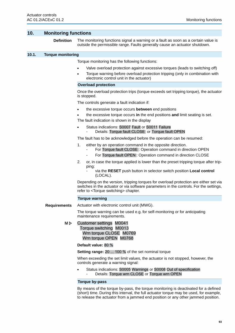
10. Monitoring functions
Definition The monitoring functions signal a warning or a fault as soon as a certain value isoutside the permissible range. Faults generally cause an actuator shutdown.
10.1. Torque monitoring
Torque monitoring has the following functions:
● Valve overload protection against excessive torques (leads to switching off)● Torque warning before overload protection tripping (only in combination with
electronic control unit in the actuator)
Overload protection
Once the overload protection trips (torque exceeds set tripping torque), the actuatoris stopped.
The controls generate a fault indication if:
● the excessive torque occurs between end positions● the excessive torque occurs in the end positions and limit seating is set.The fault indication is shown in the display
● Status indications: S0007 Fault or S0011 Failure- Details: Torque fault CLOSE or Torque fault OPEN
The fault has to be acknowledged before the operation can be resumed:
1. either by an operation command in the opposite direction.- For Torque fault CLOSE : Operation command in direction OPEN- For Torque fault OPEN : Operation command in direction CLOSE
2. or, in case the torque applied is lower than the preset tripping torque after trip-ping:- via the RESET push button in selector switch position Local control
(LOCAL).
Depending on the version, tripping torques for overload protection are either set viaswitches in the actuator or via software parameters in the controls. For the settings,refer to <Torque switching> chapter.
Torque warning
Requirements Actuator with electronic control unit (MWG).
The torque warning can be used e.g. for self-monitoring or for anticipatingmaintenance requirements.
Customer settings M0041Torque switching M0013Wrn torque CLOSE M0769Wrn torque OPEN M0768
Default value: 80 %Setting range: 20 ... 100 % of the set nominal torque
When exceeding the set limit values, the actuator is not stopped, however, thecontrols generate a warning signal:
● Status indications: S0005 Warnings or S0008 Out of specification- Details: Torque wrn CLOSE or Torque wrn OPEN
Torque by-pass
By means of the torque by-pass, the torque monitoring is deactivated for a defined(short) time. During this interval, the full actuator torque may be used, for example,to release the actuator from a jammed end position or any other jammed position.
93
Actuator controls AC 01.2/ACExC 01.2 Monitoring functions

Valve damage due to excessive torque!
→ Only apply torque by-pass with the consent of the valve manufacturer.
Customer settings M0041Torque switching M0013Torque by-pass M0092
Default value: Function not active
Setting values:
Function active The torque by-pass is activated.
Function not active The torque by-pass is deactivated.
Time interval for torque by-pass
During the time interval set here, the torque monitoring is deactivated.
Customer settings M0041Torque switching M0013Torque by-pass [s] M0205
Default value: 0.0 sSetting range: 0.0 ... 5.0 s seconds
Information If torque by-pass is activated, the interval should be longer than the set time periodfor reversing prevention time to ensure torque by-pass will also be effective in theevent of reversal of operation.
10.2. Motor protection monitoring (thermal monitoring)
In order to protect against overheating and impermissibly high temperatures at theactuator, PTC thermistors or thermoswitches are embedded in the motor winding.The thermoswitch is tripped as soon as the max. permissible winding temperaturehas been reached.
The actuator is switched off and the following signals are given:
● LED 3 (motor protection trippped) on the local controls is illuminated.● Status indication: S0007 Fault or S0011 Failure
- Details: Thermal faultThe motor has to cool down before the operation can be resumed.
Depending on the parameter setting (motor protection behaviour), the fault signal iseither automatically reset or the fault signal has to be acknowledged manually.
Manual acknowledgement can be made:
● in selector switch position Local control (LOCAL) via push button RESET.● in selector switch position Remote control (REMOTE) via a digital (I/O interface)
with the RESET command if a digital input is configured for signal.In addition, the AC cyclically (once per day) checks the motor protection monitoringfor its proper function. If this check fails, the controls generate the fault indication:IE mot. prot. monitor
Motor protection behaviour
Required user level: AUMA (6).
Device configuration M0053Actuator M0168Motor prot. mode M0169
Default values:
Non-explosion-proof actuators = Auto
94
Actuator controlsMonitoring functions AC 01.2/ACExC 01.2

Explosion-proof actuators = Reset
Setting values:
Auto Automatic reset after the motor has cooled down.
Not possible for explosion-proof version ACExC 01.2
Reset Manual reset.
Once the motor has cooled down, the fault has to be acknowledged (reset) manuallyas described above.
If required the thermal overload relay has to be reset manually. To this end, removethe cover on the back of actuator controls and operate the reset button on the thermaloverload relay.
10.3. Type of duty monitoring (motor starts and running time)
This function monitors the permissible type of duty (e.g. S2 - 15 min) of the actuator.
For this, controls monitor possible excess of
● permissible motor starts (cycles) per hour● permissible running time (on-time) per hourIf any of these values has been exceeded, the actuator will however not be stopped,but the following warning signals are issued.
● Status indications: S0005 or S0008- Details: Wrn on time starts
● Status indications: S0005 or S0008- Details: Wrn on time running
The warning signals will automatically be cleared if the permissible motor starts persecond or the permissible running time per hour are no longer reached.
The operational info logger records the number of excesses (warnings) as well asthe number of motor starts and motor running times.
Asset Management M1231Operational info M0177
Operational info M0188On time warning 1 M0325 contains total number of all on time warnings.
On time warning 2 M0326 contains maximum duration of on time warning
Example: Due to excess of defined starts/h or defined running time/h, the AC issues in total 4on time warnings: two for 5 min, once for 10 min, once for 17 min. Afterwards theoperating data counters contain the following values:
On time warning 1 M0325 = 37 min = total of all periods (5+5+10+17 min)
On time warning 2 M0326 = 17 min = longest period
Figure 55: Example
[1] Running time/h[2] Starts/h[3] On time warning
Activate on time monitoring
Required user level: Specialist (4) or higher.
Customer settings M0041On time monitoring M0355
95
Actuator controls AC 01.2/ACExC 01.2 Monitoring functions

On time monitoring M0358Default value: Function not active
Setting values:
Function not active Function <On-time monitoring> deactivated.
Function active Function <On-time monitoring> activated.
Set permissible starts/h
Customer settings M0041On time monitoring M0355Permissible starts/h M0357
Default value: 1,200 starts/h
Setting range: 1 ... 1,800 starts/h
Set permissible running time/h
Customer settings M0041On time monitoring M0355
Perm. running time/h M0356Default value: 15 min (minutes)
Setting range: 10 ... 60 min (minutes)
10.4. Operating time monitoring
This function allows the monitoring of the operating time of the actuator. If the actuatorneeds longer than the set time to move from end position OPEN to end positionCLOSED, a warning is signalled (the actuator is not stopped):
● Status indication S0005 Warnings- Details: Op. time warning
The warning indication is automatically cleared once a new operation command isexecuted.
When the actuator moves from an intermediate position to an end position, the setmonitoring time for the whole stroke is assigned in relation to the remainingstroke/travel.
Operation mode: activate
Required access level: Specialist (4) or higher.
Customer settings M0041Oper. time monitoring M0568Operation mode M0569
Default value: Off
Setting values:
Off The operating time monitoring is switched off
Manual The operating time monitoring is switched on. The permissible operation time is setvia parameter Perm.op. time, manual M0570.
Set permissible operating time manually
Required user level: Specialist (4) or higher.
Customer settings M0041Oper. time monitoring M0568Perm.op. time, manual M0570
Default value: 15:00.0 min:s (15 minutes)
96
Actuator controlsMonitoring functions AC 01.2/ACExC 01.2

Setting range: 00:00.0 ... 59:59.9 min:s (minutes:seconds)
Display operating times
Operating times can be displayed via Asset Management. Refer to <Display operatingtimes>
10.5. Reaction monitoring
The AUMATIC monitors whether the actuator moves after an operation command.
If no reaction is recorded at the output drive of the actuator within a set time, eithera warning or a fault signal is generated depending on the setting:
● Status indications: S0005 Warnings or S0008 Out of specification- Details: Wrnn no reaction
● Status indications: S0007 Fault or S0011 Failure- Details: Fault no reaction
In the event of a fault signal, the fault has to be acknowledged to be able to resumethe operation. The acknowledgement is made:
● in selector switch position Local control (LOCAL) via push button RESET.● in selector switch position Remote control (REMOTE) via a digital (I/O interface)
with the RESET command if a digital input is configured for signal.In case of operation from an intermediate position, reaction monitoring will only beperformed if the actuator is equipped with a position feedback.
Activate switching off for reaction time error
Required user level: Specialist (4) or higher.
Customer settings M0041Reaction monitoring M0632Actuator behaviour M0633
Default value: No cut-off
Setting values:
No cut-off The reaction monitoring only issues a warning.
Cut-off The reaction monitoring issues a fault signal, the actuator is stopped.
Set reaction time
Customer settings M0041Reaction monitoring M0632Reaction time M0634
Default value: 15.0 sSetting range: 15.0 ... 300.0 seconds (0 seconds up to 5 minutes)
10.6. Motion detector
— Option —
Requirements Position transmitter in the actuator.
Characteristics The motion detector checks whether the actuator moves even without operationcommand (e.g. in manual operation or if there is no self-retaining).
Controls identify motion if the actuator moves more than the pre-set travel differencewithin the predefined recording time. Controls signal: Output drive rotates
Information Parameters for motion detection have a direct impact on reaction monitoring.
10.6.1. Motion detector: activate
Required user level: Specialist (4) or higher.
97
Actuator controls AC 01.2/ACExC 01.2 Monitoring functions

Customer settings M0041Motion detector M0676Motion detector M0675
Default value: Function active
Setting values:
Function not active Monitoring is deactivated.
Function active Monitoring is activated.
10.6.2. Detection time dt
Required user level: Specialist (4) or higher.
Customer settings M0041Motion detector M0676Detect. time dt M0677Detect. time dt (MWG) M0681
Default values:
Detect. time dt (for potentiometer/EWG/RWG within actuator) = 00:05.0 min:s ( 5seconds)
Detect. time dt (MWG) (for MWG within actuator) = 00:00.5 min:s (0.5 seconds)
Setting ranges:
Detect. time dt = 00:01.0 ... 30:00.0 min:s (minutes:seconds)
Detect. time dt (MWG) = 00:00.1 ... 00:02.0 min:s (minutes:seconds)
10.6.3. Travel difference dx
Required user level: Specialist (4) or higher.
Customer settings M0041Motion detector M0676Travel diff. dx M0678Travel diff. dx (MWG) M0679
Default values:
Travel diff. dx (for potentiometer/EWG/RWG within actuator) = 1.0 %Travel diff. dx (MWG) (for MWG within actuator) = 3 (increments)
Setting ranges:
Travel diff. dx = 1.0 ... 10.0 %Travel diff. dx (MWG) = 2 ... 20 (increments)
10.6.4. Delay time
Delay time of the signal: Handwheel oper.Required user level: Specialist (4) or higher.
Customer settings M0041Motion detector M0676Delay time M0764
Default value: 6.000 s (seconds)
Setting range: 0.001 ... 65.535 s
10.7. Monitoring of electronics power supply
AC actuator controls monitor the following voltages and signals a warning (refer to<Fault signals and warnings> chapter):
● Auxiliary voltage 24 V DC, e.g for supplying the control inputs
98
Actuator controlsMonitoring functions AC 01.2/ACExC 01.2

● Voltage 24 V AC for controlling the reversing contactors, for thermoswitchesand heater within the actuator and for generating the 115 V AC auxiliary voltagefor the customer (option)
● Internal 24 V DC power supply of the electronics components (within the controlsand in the actuator)
● External 24 V DC supply of the electronics (option)
Activate monitoring of auxiliary voltage 24 V DC
Required user level: Specialist (4).
Device configuration .Monitoring functions M0645
Monitor 24 V DC cust. M0650Default value: Function not active
Setting values:
Function not active Monitoring is deactivated.
On Monitoring is activated. Should the auxiliary voltage 24 V DC for supplying the controlinputs fail, a warning will be issued.
Activate monitoring of external supply 24 V DC
Required user level: Specialist (4).
Device configuration M0053Monitoring functions M0645
Monitor 24 V DC ext. M0649Default value: Function not active
Setting values:
Function not active Monitoring is deactivated.
On Monitoring is activated. Should the external supply 24 V DC fail, a warning will beissued.
10.8. Temperature monitoring
Characteristics If the respective sensors are installed in the devices, the AUMATIC monitors differenttemperatures.
If certain temperature limits are exceeded or fallen short of, the controls either senda warning or a fault signal.
Conditions: ● for temperature within the control unit of the actuator: MWG (magnetic limit andtorque transmitter)
● For motor temperature: additionally temperature sensor (PT 100) in the motor● For gear housing temperature: additionally temperature sensor (PT 100) in the
gearing
Information Current device temperatures can also be displayed. Refer to <Display device tem-peratures>.
10.9. Heater system/heater monitoring
The heater system within the actuator controls housing and the heater on the controlunit (within the switch compartment of the actuator) can be monitored. If the monitoringis activated the following warning will be generated if the heater system or the heater(circuit = interrupted) fails:
● In the display of the local controls, status indication S0005 Warnings- Details: Internal warning Wrn heater
For further information on the heater system and the heater refer to separate <Heatersystem and heater> chapter.
99
Actuator controls AC 01.2/ACExC 01.2 Monitoring functions

Activate heater system monitoring
Heater system monitoring monitors all connected heaters for failure.
Required user level: Specialist (4).
Device configuration M0053Monitoring functions M00645Monitor heat. system M0647
Default value: Function not active
Setting values:
Function not active Heater monitoring is deactivated.
Function active Heater monitoring is activated.
Activate heater control unit monitoring
Information If a heater system is installed within the actuator controls, heater monitoring is notactivated/deactivated via this parameter, but via Monitor heat. system M0647 para-meter of the heater system.
Required user level: Specialist (4).
Device configuration M0053Actuator M0168Heater monitor M0646
Default value: Function not active
Setting values:
Function not active Heater monitoring is deactivated.
On Heater monitoring is activated. If the heater fails, a warning will be issued.
Information Monitoring can only be made once the heater is activated (parameter Heater controlunit).
Set reaction time for heater monitoring
Heater monitoring will only respond once a fault persists longer than the set monitoringtime. Short-time faults occurring for less than the set monitoring time are not signalledas warning.
Required user level: AUMA (6).
Device configuration M0053Actuator M0168Heating sys. mon. time M0859
Default value: 300.0 seconds
Setting range: 60 ... 3600 seconds (1 minute to 1 hour)
10.10. Verification of sub-assemblies
Conditions ● Actuators of the type range SA 07.2 – SA 16.2/SAR 07.2 – SAR 16.2● MWG position transmitter in actuator
Characteristics The controls verify whether sub-assemblies mounted in actuators and controlscorrespond to the desired version.
In case incorrect sub-assemblies are mounted or if sub-assemblies are missing thecontrols either send a warning or a fault signal.
For detailed information on this indication refer to <Fault signals and warnings>chapter.
100
Actuator controlsMonitoring functions AC 01.2/ACExC 01.2

10.11. Phase failure monitoring
Conditions: Phase failure monitoring is only valid for connections to 3-phase AC power supplies.For versions with 1-phase AC or DC, phase failure monitoring is not possible.
Characteristics The AUMATIC monitors phase L2. If phase L2 is missing for a certain time interval,the AUMATIC still can send and receive signals and generates a fault indication.Since the AUMATIC is supplied via phases L1 and L3, the two phases cannot bemonitored. In case L1 or L3 fails, the AUMATIC is inoperable and the actuator stops.
Information In case of phase L2 loss during motor operation, this does not necessarily lead toan immediate standstill of the actuator.The reason is that the rotating motor generatesthe missing phase itself. This leads, however, to a reduction of the motor outputtorque. If the torque is sufficient for valve operation, the missing phase L2 is onlydetected when switching off (e.g. in an end position) and the fault signal Phase faultis generated.
Configuration of the tripping time
Required user level: Specialist (4) or higher.
Device configuration M0053Phase monitoring M0170Tripping time M0172
Default value: 10.0 sSetting range: 1.0 – 300.0 s
Information Faults in supply voltage (e.g. voltage drops) do not generate a fault signal during theadjustable tripping time.
10.12. Phase sequence detection and correction of the direction of rotation
Conditions: The phase sequence detection is only valid for connections to 3-phase AC powersupplies. For versions with 1-phase AC or DC, phase sequence detection is notpossible.
Characteristics Exchanging any two phase conductors in the 3-phase mains changes the directionof phase rotation. Should the phases L1, L2 and L3 be connected in the wrongsequence, this is detected and corrected by the AUMATIC, preventing the actuatorfrom turning into the wrong direction.
Activate phase sequence detection and correction of direction of rotation
Device configuration M0053Phase monitoring M0170Adapt rotary dir. M0171
Default value: Function active
Setting values:
Function active Function <Phase sequence detection and correction of direction of rotation> isactivated.
Function not active Phase sequence detection and correction of direction of rotation is deactivated.
101
Actuator controls AC 01.2/ACExC 01.2 Monitoring functions

11. Functions: activate and enable
11.1. Activate functions
Via menu Activation M0212, functions can be switched on (activated) or off(deactivated).
Required user level for enabling/disabling: Specialist (4) or higher.
Device configuration M0053Application functions M0178Activation M0212
Information Some functions require enabling. Only enabled functions are visible and can be ac-tivated or deactivated.
Enabling requiredMenuFunctionNoM0589EMERGENCY behaviourNoM0156Timer CLOSENoM0206Timer OPENYesM0158PositionerNoM0294Operation profileYesM0741Process controllerNoM0573BluetoothYesM0631Enable LOCALYesM0770Priority REMOTEYesM0790Auto change-over I/OYesM0663InterlockYesM0851PVSTYesM0941By-pass functionYesM1087LPV functionYesM1139MPV functionNoM1136Maintenance signalsNoM1137Maintenance intervalYesM1197Limit switch. via CDTYesM1677Automatic deblockingNoM1650Split range operationYesM1679Automatic deblockingNoM1709Com. eval. REMOTE
11.2. Enable functions
Via menu Enabling M0179, optional functions can be enabled or disabled.
This menu is visible in the display from user level Specialist (4).
Device configuration M0053Application functions M0178Enabling M0179
Menu and user levelFunctionM0209 AUMA (6)PositionerM0338 AUMA (6)Process controllerM0630 AUMA (6)Enable LOCALM0771 AUMA (6)Priority REMOTEM0789 AUMA (6)Auto change-over I/OM0661 AUMA (6)InterlockM0856 AUMA (6)PVSTM0940 AUMA (6)By-pass function
102
Actuator controlsFunctions: activate and enable AC 01.2/ACExC 01.2

Menu and user levelFunctionM1088 AUMA (6)LPV functionM1138 AUMA (6)MPV functionM1198 AUMA (6)Limit switch. via CDTM1678 AUMA (6)Automatic deblocking
Information In user level Specialist (4), an additional activation password (depending on theserial number) is required for enabling the function. The activation password canonly be assigned and generated by the AUMA service.
103
Actuator controls AC 01.2/ACExC 01.2 Functions: activate and enable

12. Service functionsThe functions described here may only be changed by the AUMA service or byauthorised and trained personnel.
Menu item Service functions is only visible, if user level Specialist (4) or higher isselected.
12.1. Direction of rotation
Characteristics This function allows changing the direction of rotation for actuator with 3-phase ACmotors.
The direction of rotation indicates the direction into which the drive shaft rotatesaround its own axis. The view is on the top of the actuator. Distinction is madebetween clockwise and counterclockwise rotation.
Information ● When changing from clockwise closing to counterclockwise closing or viceversa, only the direction of rotation of the motor is changed. The change-overrequires further action:- The wiring diagram designation is marked on the AUMATIC name plate.
In case of a change, a new name plate with the new wiring diagram numberhas to be requested from AUMA.
- The wiring diagram number is stored in the electronic device ID (parameterWiring diagram actuator M0060). The ID has to be adapted to the newdesignation once the conversion is complete.
- The actuator mounted to the controls must be configured for the set direc-tion of rotation. Subsequent conversion from clockwise closing to counter-clockwise closing is possible using an AUMA conversion kit.
Parameters and instructions for setting
Setting the direction of rotation using parameters is only possible for actuators withelectronic control unit/MWG (Non-intrusive version).
Valve damage due to incorrect direction of rotation!
→ For 3-phase AC motors, the rotation direction of the actuator must match therotation direction of the valve.
Required user level: AUMA (6).
Device configuration M0053Actuator M0168Closing rotation M0176
Default value: Clockwise rotation
Setting values:
Clockwise rotation The motor is controlled with a clockwise rotating field with the following sequence:L1-U1, L2-U2, L3-U3 (clockwise closing).
Counterclockwise rot. The motor is controlled with a counterclockwise rotating field with the followingsequence: L1-U3, L2-U2, L3-U1 (counterclockwise closing).
12.2. Factory setting
The factory setting corresponds to the delivery state of the AUMATIC.
When converting the controls e.g. by the AUMA service, a new factory setting canbe generated to adapt the modified configuration.
Former factory settings can be restored.
Generate new factory setting
Required user level: Service (5) or higher.
104
Actuator controlsService functions AC 01.2/ACExC 01.2

Device configuration M0053Service functions M0222Create factory settings M0225
Generates new factory settings by accepting the current settings.
Restore factory setting
Required user level: Specialist (4) or higher.
Device configuration M0053Service functions M0222Reset factory settings M0226
Resets the current settings to factory settings.
12.3. Languages: reload
If texts are changed or if a new display language is available, the language file canbe updated from the external data carrier (SD card).
Required user level: Specialist (4) or higher.
Device configuration M0053Service functions M0222Reload languages M0227
12.4. Data export
During data export the data is saved from the device to an external data carrier (SDcard).
Export data
Comprehensive export of all data (parameters, operation data and event protocol).
Operation data is device-specific data.
Required user level: Service (5) or higher.
Device configuration M0053Service functions M0222Export all data M0223
Export parameters
Export of all parameters. No operation data is transmitted.
Required user level: Specialist (4) or higher.
Device configuration M0053Service functions M0222Export all parameters M0297
Export event report
Required user level: Specialist (4) or higher.
Device configuration M0053Service functions M0222Export event report M0298
12.5. Data import
During data import, the data is transmitted to the controls from an external datacarrier (SD card).
Import parameters
Import of all parameters. Operating data is not overwritten.
Required user level: Specialist (4) or higher.
105
Actuator controls AC 01.2/ACExC 01.2 Service functions

Device configuration M0053Service functions M0222Import all parameters M0311
12.6. Actual configuration: accept
When retrofitting controls, sub-assemblies are replaced by new sub-assemblies withdifferent functions.
Example: Replacing the PSU (different voltage).
If the controls detect a modified sub-assembly during start up, the following faultsignal is generated: Configuration error
Accept current actual configuration
Accept new actual configuration as target configuration.
Required user level: AUMA (6).
Device configuration M0053Service functions M0222Accept actual config. M0590
12.7. Firmware update
A firmware update is required in the following cases:
● Upgrade with new functions● Corrective actionsA firmware update can be performed in the following ways:
1. via Bluetooth connection using AUMA CDT software on a laptop computer orPDA
2. via an SD card (card slot in local controls)
Firmware version
The firmware version can be displayed via the following menu:
Device ID M0021Version M0062Firmware M0077
Firmware update via SD card
The menu Update firmware is only displayed if an SD card has engaged in the cardslot of the local controls.
Required access level: Service (5) or higher.
Device configuration M0053Service functions M0222Update firmware M0564
12.8. Service software AUMA CDT (Bluetooth)
AUMA CDT is a user-friendly setting and operation program for AUMA actuatorcontrols AC 01.2.
The connection between computer (PC, laptop, PDA ) and local controls is establishedwireless via Bluetooth interface.
Activate Bluetooth
Required user level: Specialist (4) or higher.
Device configuration M0053Application functions M0178Activation M0212Bluetooth M0573
106
Actuator controlsService functions AC 01.2/ACExC 01.2

Default value: Function active
Setting values:
Function not active Function deactivated.
Function active Function activated. If the connection is active, the blue LED on the local controls isilluminated.
Addresses and device tag
Required user level: Specialist (4) or higher.
Diagnostic M0022Bluetooth M0244Device tag M0423Bluetooth address M0422Bluetooth add.partner M0576
107
Actuator controls AC 01.2/ACExC 01.2 Service functions

13. DiagnosticsDiagnostics comprise information on the device and on device sub-assemblies forsupport during commissioning, maintenance or corrective action.
13.1. Electronic device ID
The electronic device ID provides information about the order data (important forenquiries with the factory).
Device ID M0021Identification M0026Version M0062
Information on device identifications can be modified with the appropriate rights (userlevel).
Table 10: Information on device identifications
Identification M0026User level re-quired for modi-fication
DescriptionIndication on display
Service (5)AUMATIC device designationDevice designation M0072Specialist (4)Device ID for identification within
the plant marking (e.g. KKS(Power Plant Classification Sys-tem)
Device tag M0070
Specialist (4)Project name of the plantProject name M0068Menu with information regarding identification of theAUMATIC
Controls M0028
Service (5)Order number of the AUMATICOrder no. controls M0055Service (5)Serial number of AUMATICSerial no. controls M0056Service (5)Wiring diagram number of AUMAT-
ICWiring diagram M0059
Service (5)Date of manufacture of controlsDate of manufacture M0063Menu with information regarding identification of theactuator
Actuator M0029
Service (5)Order number of the actuatorOrder no. actuator M0057Service (5)Works number of actuatorSerial no. actuator M0220Service (5)Wiring diagram number of actuat-
orWiring diagram actuator M0060
Table 11: Information on device version
Version M0062DescriptionIndication on displayFirmware versionFirmware M0077Language versionLanguage M0565Menu with further items for requesting the current ImageFile versions of current sub-assemblies (only visible foruser level AUMA (6))
Details Firmware M0515
Menu with further items for requesting the hardwarearticle number of the actual sub-assemblies (only visiblefor user level AUMA (6))
Hardware art. no. M0684
13.2. Diagnostic Bluetooth connection
Menu is only visible if function Bluetooth M0573 is activated.
Required user level: Specialist (4) or higher.
Diagnostic M0022Bluetooth M0244
The following states can be checked via diagnostic:
108
Actuator controlsDiagnostics AC 01.2/ACExC 01.2

SignificationMenu IDParametersInformation for actuator identification within the plant(e.g. KKS designation - Power Plant Classification sys-tem)(Can be changed for user level Specialist (4) and higher)
M0223Device tag
Bluetooth address (BD_ADDR) of controlsM0222Bluetooth addressBluetooth address (BD_ADDR) of the Bluetooth partnerM0576Bluetooth add.partner
13.3. Diagnostic Interface
Required user level: Specialist (4) or higher.
Diagnostic M0022Interface M0239
The following states can be checked via the menu:
SignificationMenu IDParametersShows configuration, coding and state of the input sig-nals.
M0245States DIN
Shows configuration and current value at analogue input1.
M0246States AIN 1
Shows configuration and current value at analogue input2.
M0583States AIN 2
Shows configuration, coding and state of the outputsignals.
M0247States DOUT
Shows configuration and current value at analogueoutput 1.
M0248States AOUT 1
Shows configuration and current value at analogueoutput 2.
M0584States AOUT 2
Status of the interfaceM0730Interface status
Diagnostics of digital inputs
For the digital inputs (DIN), both coding and signal states are indicated at the inputby means of symbols.
Table 12: Symbol explanation
Input stateSignal (command)CodeSymbolLow level = 0 V or input openNot activeHigh active
High level = Default: +24 V DCActiveHigh active
High level = Default: +24 V DCNot activeLow active
Low level = 0 V or input openActiveLow active
Figure 56: Example of DIN 4 and DIN 5
● Configuration:- DIN 4: Operation command OPEN- DIN 5: Operation command for EMERGENCY behaviour
● Coding:- DIN 4: High active (Triangle pointing in upward direction)- DIN 5: Low active (Triangle pointing in downward direction)
109
Actuator controls AC 01.2/ACExC 01.2 Diagnostics

● Signal state at input:- DIN 4: Not active (triangle not filled in)
Low level = 0 V = No operation command in direction OPEN- DIN 5: Active (triangle is black)
Low level = 0 V = EMERGENCY operation command is available
Diagnostic of digital outputs
For the digital outputs (DOUT), both coding and signal states are indicated at theoutput by means of symbols.
Table 13: Symbol explanation
State output (output contact)Signal (indication)CodeSymbolLow = 0 (output contact not operated)Not activeHigh active
High = 1 (output contact operated)ActiveHigh active
High = 1 (output contact operated)Not activeLow active
Low = 0 (output contact not operated)ActiveLow active
Figure 57: Example of DOUT 1 and DOUT 2
● Configuration:- DOUT 1: Indication: Fault has occurred.- DOUT 2: Indication: End position CLOSED reached
● Coding:- DOUT 1: Low active (Triangle pointing in downward direction)- DOUT 2: High active (Triangle pointing in upward direction)
● Signal state at output:- DOUT 1: Not active (triangle not filled in)
High level = +24 V DC = no indication (no fault available)- DOUT 2: Active (triangle is black)
High level = +24 V DC= indication (end position CLOSED reached)
13.4. Diagnostic Position transmitter potentiometer
Menu is only visible if the actuator is equipped with potentiometer.
Required user level: Observer (1) or higher.
Diagnostic M0022Position transm. potent. M0831
The following states can be checked via diagnostic:
SignificationMenu IDParametersLow limit setting of potentiometer signal range (monitor-ing the potentiometer span)
M0832Low limit Uspan
Current voltage level difference of the potentiometer.M0833Volt.level diff. potent.Raw value end position OPENM0999Raw val. pos. OPENRaw value end position CLOSEDM1001Raw val. pos. CLOSEDPotentiometer raw value /mVM1005Potent. raw value /mV
13.5. Diagnostic Position transmitter RWG
Menu is only visible if the actuator is equipped with electronic position transmitter(RWG).
110
Actuator controlsDiagnostics AC 01.2/ACExC 01.2
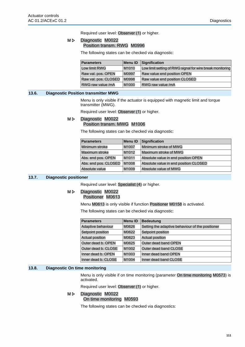
Required user level: Observer (1) or higher.
Diagnostic M0022Position transm. RWG M0996
The following states can be checked via diagnostic:
SignificationMenu IDParametersLow limit setting of RWG signal for wire breakmonitoringM1010Low limit RWGRaw value end position OPENM0997Raw val. pos. OPENRaw value end position CLOSEDM0998Raw val. pos. CLOSEDRWG raw value /mAM1000RWG raw value /mA
13.6. Diagnostic Position transmitter MWG
Menu is only visible if the actuator is equipped with magnetic limit and torquetransmitter (MWG).
Required user level: Observer (1) or higher.
Diagnostic M0022Position transm. MWG M1006
The following states can be checked via diagnostic:
SignificationMenu IDParametersMinimum stroke of MWGM1007Minimum strokeMaximum stroke of MWGM1012Maximum strokeAbsolute value in end position OPENM1011Abs. end pos. OPENAbsolute value in end position CLOSEDM1008Abs. end pos. CLOSEDAbsolute value of MWGM1009Absolute value
13.7. Diagnostic positioner
Required user level: Specialist (4) or higher.
Diagnostic M0022Positioner M0613
Menu M0613 is only visible if function Positioner M0158 is activated.
The following states can be checked via diagnostic:
BedeutungMenu IDParametersSetting the adaptive behaviour of the positionerM0626Adaptive behaviourSetpoint positionM0622Setpoint positionActual positionM0623Actual positionOuter dead band OPENM0625Outer dead b. OPENOuter dead band CLOSEM1002Outer dead b. CLOSEInner dead band OPENM1003Inner dead b. OPENInner dead band CLOSEM1004Inner dead b. CLOSE
13.8. Diagnostic On time monitoring
Menu is only visible if on time monitoring (parameter On time monitoring M0573) isactivated.
Required user level: Observer (1) or higher.
Diagnostic M0022On time monitoring M0593
The following states can be checked via diagnostics:
111
Actuator controls AC 01.2/ACExC 01.2 Diagnostics

SignificationMenu IDParametersCurrent on time/hM0594On time/hCurrent starts/hM0595Starts/h
13.9. Diagnostic Process controller
Required user level: Specialist (4) or higher.
Diagnostic M0022Process controller M0883
Menu M0883 is only visible if function Process controller M0741 is activated.
The following states can be checked via diagnostic:
SignificationMenu IDParametersProcess setpoint of PID controllerM0884Process setpointActual process value of PID controllerM0885Actual process valueCalculated setpoint position for subordinate controllerM0886Op. com. PID contr.
13.10. Diagnostic FQM (fail safe)
The menu will only be visible if a fail safe unit (FQM) is connected to the actuator.
Required user level: Observer (1) or higher.
Diagnostic M0022FO cables M0638
The following states can be checked via diagnostic:
SignificationMenu IDParameters"FQM FS ready" active means that the FQM unit isready to perform a fail safe operation
M1725FQM FS ready
"FQM FS diag. result" active means that the diagnosticresult of winding and blinker contact is indicated asfaulty.
M1726FQM FS diag. result
FQM (fail safe) is in end position corresponding to thefail safe position (depending on the configuration, thiscan be OPEN or CLOSED)
M1727FQM fail safe end.pos.
- "FQM FS-PosOk" active means, that constant forcespring and toggle lever switch are both operation (thesolenoid switch is being controlled).
M1728FQM FS-PosOk
Fail safe function of FQM (fail safe) is requested. (ESDrequested).
M1729FQM request
"FQM timeout tension" active means, that the windingprocedure was not completed within the permissibleinitialisation time of 2.5 minutes.
M1730FQM timeout tension
13.11. Simulation (inspection and test function)
The service personnel or the commissioning engineer can use this simulation functionto simulate the operation and failure behaviour of the actuator or the AUMATIC tocheck the interface to the DCS and the correct behaviour of the DCS.
13.11.1. Actuator signals
By simulating the actuator signals, the signal behaviour of the AUMATIC to the DCScan be tested, for example, without having to connect the actuator.
Required user level: Service (5) or higher.
Diagnostic M0022Simulation M0023Actuator signals M0024
112
Actuator controlsDiagnostics AC 01.2/ACExC 01.2

Simulation values:
End position OPEN End position OPEN reached.
End position CLOSED End position CLOSED reached.
Torque fault OPEN Torque in direction OPEN reached.
Torque fault CLOSE Torque in direction CLOSE reached.
Thermal fault Motor protection tripped (thermal fault)
The simulation is activated and deactivated by push button Ok.
A loop on the display indicates that the simulation is active.
13.11.2. Interface signals
By simulating the interface signals, the signal behaviour of the AUMATIC to the DCScan be tested, for example, without having to connect the actuator.
Required access level: Specialist (4) or higher.
Diagnostic M0022Simulation M0023Signals DOUT M0025Signals AOUT 1 M0413Signals AOUT 2 M0585
Signals for simulating digital outputs:
Only the assigned outputs are displayed.
Numbers 1, 2, 3, ... indicate the digital output.
Example: 1 FaultIndication Fault is assigned to digital output 1 (parameter Signal DOUT 1 M0109).
Simulation is activated and deactivated by push button Ok.
Triangles indicate the activation:
Triangle pointing in upward direction: Output is coded high active.
High active (voltage is present, e.g. + 24 V DC)
High active (voltage is not present)
Triangle pointing in downward direction: Output is coded low active.
Low active (voltage is not present)
Low active (voltage is present, e.g. + 24 V DC)
Signals for simulating analogue outputs:
Signals AOUT 1 Simulation of output signal Actual position, setting range: 0 ... 20 mA
Signals AOUT 2 Simulation of output signal Torque, setting range: 0 ... 20 mA
113
Actuator controls AC 01.2/ACExC 01.2 Diagnostics

14. Plant Asset ManagementThe <Asset Management> function provides information (operational data, signals,reports and characteristics), which can be used within an Asset Management Systembut also generally for support during commissioning, maintenance or correctiveaction.
14.1. Operating data
Operating data provides details e.g. about the running time, the number of starts,number of torque faults etc.
The analysis of this data provides valuable information regarding the optimization ofboth actuator and valve.When using this information purposefully, actuator and valvewill be carefully operated, e.g. through appropriate parameter setting. In case offaults, the logging of operating data allows for quick fault diagnostic.
View the operating data
Two counters are available, a lifetime counter and a resettable counter.
Asset Management M1231Operational info M0177
Operational info total M0183Operational info M0188Description of the indications:
Operational info total = Lifetime counter
Operational info = Counter can be reset to 0
Table 14: Operating data
DescriptionIndication on displayMotor running timeMotor running timeNumber of motor starts (starts)Motor startsNumber of thermal faults (motor protection)No. thermal faultsNumber of torque faults in direction CLOSETorque fault CLOSENumber of torque faults in direction OPENTorque fault OPENNumber of limit switch trippings in direction CLOSELimit trip CLOSEDNumber of limit switch trippings in direction OPENLimit trip OPENNumber of torque switch trippings in direction CLOSETorque trip CLOSENumber of torque switch trippings in direction OPENTorque trip OPENTotal of all time intervals during which a start/run warn-ing was signalled.
On time warning 1
Max. time interval during which a start/run warning wassignalled.
On time warning 2
Total of AUMATIC system startsNo. system startsMaximum temperature of the controlsMax. tem. controlsMinimum temperature of the controlsMin. temp. controlsMaximum temperature of the MWGMax. temp. MWGMinimum temperature of the MWGMin. temp. MWGMaximum vibration of actuatorMax. vibrationOperating hours counter: Number of hours during whichcontrols are supplied with power
Operating hours
Reset operating data
Required user level: Specialist (4) or higher.
Asset Management M1231Operational info M0177
Reset operation. info M0197
114
Actuator controlsPlant Asset Management AC 01.2/ACExC 01.2

The entries in the operating data logging can be reset (deleted) via this menu.
14.2. Event report
The event report records system events and status signals. The event record canbe exported to the external SD card or read via AUMA CDT software. This allowsconclusions on previous actuator and valve operations, for example.
Information Since the events are recorded with a time-stamp, date and time (parameter Dateand time M0221) should be properly set.
Event filter for system events
The AUMATIC records system events such as operation commands or modificationson the parameter settings. A filter is used to define the system events to be recordedin the event report.
Required user level: AUMA (6).
Asset Management M1231Event report M0195
System event filter M0334An event is recorded (i.e. filter is active) if a black dot is placed behind the valuedisplayed.
Events which can be recorded:
Commands All operation commands recognised as valid and executed are recorded. Thecommand source of the operation command is also recorded.
Parameterization All modifications of parameter settings are also recorded. Both former and new valueare recorded.
Enable processes The enabling of a function is recorded.
System events All important system events are recorded. These include: System start, change ofdate, downloads, modifications of the event filter, resetting of operating data andswitching on the mains voltage.
Event filter for status indications
The AUMATIC records status indications such as faults, errors, warnings or Actuatoris in end position CLOSED/OPEN. A filter is used to define the status indications tobe recorded in the event report.
Required user level: AUMA (6).
Asset Management M1231Event report M0195
Event filter for Events M0333An event is recorded (i.e. filter is active) if a black dot is placed behind the valuedisplayed.
Events which can be recorded:
The events which can be selected here are described in the <Faults and warnings>chapter.
File size of event report
The file size of the event report can be modified to record more or less events asdesired. If the file is full, the oldest events will be overwritten so that the latest andcurrent events are recorded.
Required user level: AUMA (6).
Asset Management M1231Event report M0195
File size M0330
115
Actuator controls AC 01.2/ACExC 01.2 Plant Asset Management

Default value: 548 [kByte]
Setting range: 1 ... 1,024 [kByte]
With the maximum setting range of 1,024 kbyte, at least 20,000 events can be stored.
Information Some events are stored in a sector which cannot be overwritten. This includes, forexample, modifications of the parameter setting, enabling of functions and certainspecial functions.
Number of events in the buffer
The events are first stored into an internal RAM. From this buffer, they are writtento the event report after the set report cycle. The number of events in the buffer canbe set here.
Information In case of power failure, the events in the buffer will be lost.
Required user level: AUMA (6).
Asset Management M1231Event report M0195
Buffer size M0332Default value: 50 [events]
Setting range: 10 ... 100 [events]
Save interval
The event report is updated and saved at a defined cycle. This cycle (save interval)can be reduced or extended
Required user level: AUMA (6).
Asset Management M1231Event report M0195
Save interval M0331Default value: 50,000Setting range: 1 000 ... 65 535 [ms]
14.3. Characteristics
14.3.1. Torque-travel characteristic
Conditions ● Actuators with electronic control unit● Actuator controls AC 01.2 (non-intrusive version) from firmware version 02.03.01
Characteristics Representation of torque requirement across complete travel (resolution of 0.1 %)During each travel, the controls continuously record the torques applied.
Application When comparing two characteristics (current characteristic with archivedcharacteristic), the wear within the valve or the actuator can be assessed.
Display torque-travel characteristics
Asset Management M1231Characteristics M0313
Torque-travel M1229Characteristics M05463 characteristics with two diagrams each (direction OPEN and direction CLOSE) aredisplayed while the arrow indicates the operation direction diagram.
Each characteristic has a designation (e.g. _REF 1_), which can be changed.
Use push buttons Up ▲ Down ▼ to change between characteristics.
116
Actuator controlsPlant Asset Management AC 01.2/ACExC 01.2

Figure 58: Example of torque-time characteristic
– – – Set tripping torque- - - - Min. adjustable tripping torque
Diagram for direction CLOSEDiagram for direction OPEN
The displayed characteristics are records which were previously saved.
The following further information is saved with the characteristic (can be requestedvia push button Details)
● Saving date: Time of last torque measurement● Starting date: Time of first torque measurement● Scaling:Y-axis (torque)● Tripping torque: Set torque in direction OPEN/CLOSE● Min tripping torque Min. adjustable tripping torque● Max. value: Max. measured torque value● Mean value: Calculated mean value
Characteristics recording procedure
1. Reset characteristics (clear buffer)2. Change characteristic designation3. Record characteristic: Perform operation (e.g. CLOSE-OPEN-CLOSE)4. Save characteristic
Reset characteristic
This parameter is used to reset the data in the buffer (RAM).
Required user level: Specialist (4) or higher.
Asset Management M1231Characteristics M0313
Torque-travel M1229Reset characteristic M0656After resetting the buffer, new characteristics can be recorded and saved.
Change characteristic designation
Each of the three characteristics can be named with an additional 20 characters.
Required user level: Specialist (4) or higher.
Asset Management M1231Characteristics M0313
Torque-travel M1229Tag torque-position 1 M0658Tag torque-position 2 M0659Tag torque-position 3 M0660
Record characteristic: Perform operation (e.g. CLOSE-OPEN-CLOSE)
Set selector switch to position Local control (LOCAL) or Remote control (REMOTE)to record the characteristic.
117
Actuator controls AC 01.2/ACExC 01.2 Plant Asset Management

Save characteristics
3 characteristics can be saved.
Each characteristic consists of two charts (direction OPEN and direction CLOSE).
When saving, data is transferred from the buffer (RAM) to the read-only memory(ROM).
Required user level: Specialist (4) or higher.
Asset Management M1231Characteristics M0313
Torque-travel M1229Save characteristic 1 M0652Save characteristic 2 M0653Save characteristic 3 M0654
14.3.2. Position-time characteristic
Conditions ● Actuator of the type range SA 07.2 – SA 16.2/SAR 07.2 – SAR 16.2● MWG position transmitter in actuator
Characteristics During recording, the current position, for modulating actuators also the setpointposition, within an adjustable time interval (between 1 second and 1 hour).
Application By assessing the position-time characteristics, the control behaviour can be assessedor insights on the use of the actuator can be gained.
Display position-time characteristics
Asset Management M1231Characteristics M0313
Position-time M0806Each characteristic has a designation:
ACTUAL-POSITION = actual position
NOMINAL-POSITION = setpoint position (modulating actuators only)
Use push buttons Up ▲ Down ▼ to change between characteristics.
Figure 59: Example of position-time characteristic
– – – 50 % (position between OPEN = 100 % and CLOSED = 0 %)
The following further information is saved with the characteristic (can be requestedvia push button Details)
● Saving date: Time of last position measurement● Starting date: Time of first position measurement● Scaling:Y-axis (position)
Set resolution (time interval)
Actuator controls records 10,000 measured values Set resolution of e.g. approx. 1second (parameter Interval position-time = 1 [s] ) results in a recording time of 2.7hours (10 000 seconds). Once this value has been exceeded, the former positionswill be overwritten (ring buffer)
Required user level: Specialist (4) or higher.
Asset Management M1231
118
Actuator controlsPlant Asset Management AC 01.2/ACExC 01.2

Characteristics M0313Interval position-time M0805Default value: 10 [s]
Setting values: 1 ... 3600 [s]
14.3.3. Temperature-time characteristic
Characteristics Up to four temperature-time characteristics can be recorded unless the devices arefitted with suitable sensors.
Conditions ● For recording the temperature within the control unit:MWG (magnetic limit and torque transmitter)
● For recording the temperature within the motor:additionally temperature sensor (PT 100) in the motor
● For recording the temperature within the gear housing:additionally temperature sensor (PT 100) in the gearing
Application Evaluation of the temperature-time characteristics allows to gain knowledge aboutthe service conditions (ambient temperatures) of the actuator.
Display temperature-time characteristic
Asset Management M1231Characteristics M0313
Temperature-time M0714Up to four characteristics are shown in the display.
CONTROLS TEMPERATURE = temperature within the control unit
MWG TEMPERATURE = MWG temperature
MOTOR TEMPERATURE = temperature within the motor
GEAR TEMPERATURE = within the gear housing
Use push buttons Up ▲ Down ▼ to change between available characteristics.
Figure 60: Example of temperature-time (within the control unit)
- - - 0° line¦ Recording interrupted e.g. due to power failure
AC display shows temperature evolution during one week. AUMA CDT softwarereads out the evolution during an entire year.
The following further information is saved with the characteristic (can be requestedvia push button Details)
● Saving date: Time of last temperature measurement● Starting date: Time of first temperature measurement● Scaling:Y-axis (temperature)● Min. value: Minimum measured value● Max. value: Maximum measured value
14.4. Histograms
14.4.1. Motor running time-position (histogram)
Conditions ● Actuators of the type range SA 07.2 – SA 16.2/SAR 07.2 – SAR 16.2
119
Actuator controls AC 01.2/ACExC 01.2 Plant Asset Management

Characteristics The entire travel (from 0 – 100 %) is divided into 20 segments for recording the motorrunning time.When passing a segment, the counter, shown as bar graph, increments.The histogram is cyclically saved once a minute, in case a change has occurred.
Application The motor running time position histogram shows the travel range within which theactuator is predominantly operated. This allows to draw conclusions for the sizingof the valve.
Display motor running time-position
Asset Management M1231Histograms M0712
Motor run.time-position M0713Figure 61: Example of a motor running time position histogram
The following detailed information is saved with the histogram (may be called up viapush buttons Details)
● Starting date:; Date of first running time measurement● Saving date:; Date of last running time measurement● Scaling:Y-axis (motor running time)
14.4.2. Motor running time-temperature (histogram)
Conditions ● MWG position transmitter in actuator● Temperature sensor in the motor (option)
Characteristics The motor temperature is divided into the following segments:
< –20°C to –10°C, > –10°C to 0°C, > 0°C to 10°C, ..., 120°C to 130°C, > 130°C to140°C, > 140°C.
During each operation, the counter of the segment corresponding to the currentmotor temperature will be incremented. The result is shown in a bar chart. Thehistogram is cyclically saved once a minute, in case a change has occurred.
Application The histogram indicates the ambient conditions (temperatures) at which the actuatormotor was predominantly operated.
Display motor running time-temperature
Asset Management M1231Histograms M0712
Motor run.time-temp. M0715Figure 62: Example of motor running time - motor temperature histogram
The following further information is saved with the histogram (can be requested viapush button Details)
● Starting date: Date of first running time measurement● Saving date: Date of last running time measurement● Scaling:Y-axis (motor running time)
120
Actuator controlsPlant Asset Management AC 01.2/ACExC 01.2

14.4.3. Acceleration-frequency (histogram)
Conditions MWG position transmitter in actuator
Characteristics The histogram show the percentage distribution of exceeded acceleration. Exceedingof the acceleration limits preset in the factory is recorded in ten different frequencyranges with 20 Hz each (0 – 20 Hz, ..., 180 – 200 Hz).
Application The histogram indicates the frequency range within which the actuator was exposedto vibration for example (e.g. vibration with the pipeline). Impermissibly high orpersisting vibration can destroy components of the actuator.
Display acceleration-frequency
Asset Management M1231Histograms M0712
Acceleration-frequency M0716Figure 63: Example of acceleration-frequency histogram
The following further information is saved with the histogram (can be requested viapush button Details)
● Starting date: Date of first measurement● Saving date: Date of last measurement● Scaling:Y-axis (acceleration)
14.4.4. Motor running time-torque (histogram)
Conditions MWG position transmitter in actuator
Characteristics The torque scale is divided into the following segments for both directions(OPEN/CLOSE):
from 0 – 30 %
from 30 – 110 % (8 segments with a width of 10 % each)
more than 110 %
During each operation, the counter of the segment corresponding to the currentlyrequired torque will be incremented.The result is shown in a bar chart.The histogramis cyclically saved once a minute, in case a change has occurred.
Application The motor running time-torque histogram indicates the actuator load during servicelife.
Display motor running time-torque
Asset Management M1231Histograms M0712
Motor run.time-torque M0830Figure 64: Example of motor running time-torque histogram
The following further information is saved with the histogram (can be requested viapush button Details)
121
Actuator controls AC 01.2/ACExC 01.2 Plant Asset Management

● Starting date:.● Saving date:.● Scaling:.
14.5. Maintenance (information and signals)
Characteristics AC actuator controls monitor various parameters set in the factory which have animpact on the wear of the actuator. Once one of these parameters exceeds adetermined limit, actuator controls generate a signal:
● Status indication: S0005 Warnings (AUMA category)- Details: Maintenance required
● Status indication: S0010 Maintenance required (NAMUR category)- Details: shows the parameter(s) for which the limit was exceeded, causing
the Maintenance required signal.
Apart from the parameter monitoring preset in the factory (MT lifetimemechanics/O-rings/lubricant/contactors), a fixed maintenance interval can additionallybe configured, triggering the same signal when exceeding the configured time.
The current maintenance status of the monitored parameters is represented in a barchart.
Once maintenance is complete, the parameter initiating maintenance must be resetto zero.
Application Maintenance on demand, i.e. the function can be used to perform maintenancedepending on the intensity and load of the actuator.
Activate maintenance signals
Required user level: Specialist (4) or higher.
Device configuration M0053Application functions M0178
Activation M0212Maintenance signals M1136Default value: Function not active
Setting values:
Function not active <Maintenance signals> function deactivated.
Function active <Maintenance signals> function activated.
Activate <Maintenance interval> function
Required user level: Specialist (4) or higher.
Device configuration M0053Application functions M0178
Activation M0212Maintenance interval M1137Default value: Function not active
Setting values:
Function not active <Maintenance interval> function deactivated.
Function active <Maintenance interval> function activated.
Display maintenance information
Maintenance signals M1231Maintenance M1644
Maintenance informat. M1037
122
Actuator controlsPlant Asset Management AC 01.2/ACExC 01.2

Figure 65: Example of bar chart
The bar charts indicates the current consumption of the following lifetime accounts:
Lifetime mechanics
Lifetime seals (O-rings)
Lifetime lubricants
Lifetime contactors
Maintenance interval (adjustable)
Once a bar reaches the threshold (- - - ), maintenance will be required.
Reset parameter
Once maintenance is complete, the parameter initiating the maintenance must bereset.
Starting from Maintenance informat. M1037 indication, you can change via Edit tothe reset mode.
Required user level: Specialist (4) or higher.
Device configuration M0053Application functions M0178
Activation M0212Figure 66:
Use push buttons Up ▲ Down ▼ to select the desired parameter. The arrow belowthe symbols shows the selected parameter. Pressing push button Reset resets thelifetime account of the selected parameter to zero.
Set maintenance interval
Parameters for setting a defined maintenance interval. Once the set time has elapsed,a maintenance signal is issued.
Required user level: Specialist (4) or higher.
Maintenance signals M1231Maintenance M1644
Maintenance interval M1233Default value: 10 years
Setting range: 1 month... 10 years
View/set mechanics setting values
The lifetime of the mechanics depends on the number of starts of the actuator. If anMWG is installed in the actuator, the number of completed turns including torquepresent will also be accounted for.
123
Actuator controls AC 01.2/ACExC 01.2 Plant Asset Management

Required user level: Service (5) or higher.
Maintenance signals M1231Maintenance M1644
Limit starts OPEN M1645Limit starts CLOSE M1646Limit turns OPEN M1647Limit turns CLOSE M1648
14.6. Operating times: display
Characteristics The actuator controls automatically determine the operating time for an operationbetween two end positions. For both directions (from OPEN to CLOSE and fromCLOSE to OPEN), the last determined value is saved within a parameter.
Application Operating time measurement indicated how an actuator installed in plant or acombination of actuator/gearbox/valve behave with regard to inertia without performingan operation and measuring the time manually.
Display measured operating times
Asset Management M1231Operating time M1232
Operating time CLOSE M1234Operating time OPEN M1235Indications:
Operating time CLOSE Indicates the measured operating time for the last operation in direction CLOSE
Operating time OPEN Indicates the measured operating time for the last operation in direction OPEN
14.7. Device temperatures: display
Required user level: Specialist (4) or higher.
Asset Management M1231Device status M0592
Device temperatures M0524Indications:
Temp. controls Indication of current temperature in controls housing
Temp. control unit Indication of current temperature in control unit of the actuator (actuator housing)
124
Actuator controlsPlant Asset Management AC 01.2/ACExC 01.2

15. Corrective action
15.1. Primary fuses
The AUMATIC has to be opened to replace the primary fuses. For detailedinformation, refer to operation instructions for actuator.
15.2. Fault indications and warning indications
Faults interrupt or prevent the electrical actuator operation. In the event of a fault,the display backlight is red.
Warnings have no influence on the electrical actuator operation. They only servefor information purposes.
Collective signals include further indications which can be displayed via the Details push button.
Table 15: Faults and warnings via status indications in the display
RemedyDescription/causeIndication on displayFor a description of the status texts, refer to<Status texts in Menu S0001>.
Instead of the valve position, a status text isdisplayed.
S0001
For indicated value > 0: Press push button Details.For details, refer to <Warnings and Out ofspecification> table.
Collective signal 02:Indicates the number of active warnings.
S0005Warnings
For indicated value > 0: Press push button Details.For details, refer to <Not ready REMOTE andFunction check> table.
Collective signal 04:Indicates the number of active signals.
S0006Not ready REMOTE
For indicated value > 0: Press push button Details to display a list of detailed indications.For details, refer to <Faults and Failure> table.
Collective signal 03:Indicates the number of active faults.The actuator cannot be operated.
S0007Fault
For indicated value > 0: Press push button Details.For details, refer to <Warnings and Out ofspecification> table.
Collective signal 07:Indication according to NAMUR recommenda-tion NE 107Actuator is operated outside the normal oper-ation conditions.
S0008Out of specification
For indicated value > 0: Press push button Details.For details, refer to <Not ready REMOTE andFunction check> table.
Collective signal 08:Indication according to NAMUR recommenda-tion NE 107The actuator is being worked on; output sig-nals are temporarily invalid.
S0009Function check
For indicated value > 0: Press push button Details to display a list of detailed indications.
Collective signal 09:Indication according to NAMUR recommenda-tion NE 107Recommendation to perform maintenance.
S0010Maintenance required
For indicated value > 0: Press push button Details to display a list of detailed indications.For details, refer to <Faults and Failure> table.
Collective signal 10:Indication according to NAMUR recommenda-tion NE 107Actuator function failure, output signals areinvalid
S0011Failure
125
Actuator controls AC 01.2/ACExC 01.2 Corrective action

Table 16: Warnings and Out of specification
RemedyDescription/causeIndication on display
Press push button Details to display a listof individual indications.For a description of the individual signals referto <Individual signals> table/ Config. warning(collective signal 06).
Collective signal 06:Possible cause:Configuration setting is incorrect.The device can still be operated with restric-tions.
Config. warning
Press push button Details to display a listof individual indications.For a description of the individual signals referto <Individual signals> table/ Internal warning(collective signal 15).
Collective signal 15:Device warningsThe device can still be operated with restric-tions.
Internal warning
Check 24 V DC voltage supply.The external 24 V DC voltage supply of thecontrols has exceeded the power supply limits.
24 V DC external
● Check modulating behaviour of actuator.
● Check parameter Perm. running time/hM0356, re-set if required.
Warning on time max. running time/h ex-ceeded
Wrn on time running
● Check modulating behaviour of actuator.
● Check parameter Permissible starts/hM0357, re-set if required.
Warning on time max. number of motor starts(starts) exceeded
Wrn on time starts
Verify signals:● Setpoint E1
● Actual value E2
● Actual process value E4
The failure behaviour is active since all re-quired setpoints and actual values are incor-rect.
Failure behav. active
Check wiring.Warning: Loss of signal analogue input 1Wrn input AIN 1Check wiring.Warning: Loss of signal analogue input 2Wrn input AIN 2Check setpoint signal.Warning: Loss of signal of actuator setpoint
positionPossible causes:Input signal for setpoint = 0 (signal loss)
Wrn setpoint position
The warning indications are automaticallycleared once a new operation command isexecuted.● Check valve.
● Check parameter Perm.op. time, manualM0570.
The set time (parameter Perm.op. time,manual M0570) has been exceeded. Thepreset operating time is exceeded for a com-plete travel from end position OPEN to endposition CLOSED.
Op. time warning
Measure/reduce ambient temperature.Temperature within controls housing too highWrn controls temp.Check actuator sizing, correct accordingly.Temperature within motor winding too highWrn motor temp.Check actuator sizing, correct accordingly.Temperature within actuator gear housing too
highWrn gearbox temp.
Set time.Real time clock has not yet been set.Time not setReplace button cell.Voltage of the RTC button cell is too low.RTC voltageCheck actuator (PVST settings).Partial Valve Stroke Test (PVST) could not be
successfully completed.PVST fault
Perform RESET or restart PVST.Partial Valve Stroke Test (PVST) was abortedor could not be started.
PVST abort
● Check movement at actuator.
● Check parameter Reaction time M0634.
No actuator reaction to operation commandswithin the set reaction time.
Wrnn no reaction
Check/repair FO cables.Optical receiving signal (channel 1) incorrect(no or insufficient Rx receive level) or RS-485format error (incorrect bit(s))
Wrn FOC
Check/repair FO cables.Warning: FO cable system reserve reached(critical or permissible Rx receive level)
Wrn FO cable budget
126
Actuator controlsCorrective action AC 01.2/ACExC 01.2

RemedyDescription/causeIndication on displayFit FO cable connection.Warning FO cable connection is not available.Wrn FOC connectionCheck parameter Wrn torque OPEN M0768,re-set if required.
Limit value for torque warning in directionOPEN exceeded.
Torque wrn OPEN
Check parameter Wrn torque CLOSEM0769,re-set if required.
Limit value for torque warning in directionCLOSE exceeded.
Torque wrn CLOSE
Table 17: Faults and Failure
RemedyDescription/causeIndication on display
Press push button Details to display a listof individual indications.For a description of the individual signals referto <Individual signals> table/ Configurationerror (collective signal 11).
Collective signal 11:Configuration error has occurred.
Configuration error
Press push button Details to display a listof individual indications.For a description of the individual signals referto <Individual signals> table/ Config. errorREMOTE (collective signal 22).
Collective signal 22:Configuration error has occurred.
Config. error REMOTE
AUMA servicePress push button Details to display a listof individual indications.For a description of the individual signals referto <Individual signals> table/ Internal error(collective signal 14).
Collective signal 14:Internal error has occurred.
Internal error
Perform one of the following measures:● Issue operation command in direction
OPEN.
● Set selector switch to position Local con-trol (LOCAL) and reset fault indication viapush button RESET.
Torque fault in direction CLOSETorque fault CLOSE
Perform one of the following measures:● Issue operation command in direction
CLOSE.
● Set selector switch to position Local con-trol (LOCAL) and reset fault indication viapush button RESET.
Torque fault in direction OPENTorque fault OPEN
Test/connect phases.● When connecting to a 3-ph AC system andwith internal 24 V DC supply of the elec-tronics: Phase 2 is missing.
● When connecting to a 3-ph or 1-ph ACsystem and with external 24 V DC supplyof the electronics: One of the phases L1,L2 or L3 is missing.
Phase fault
Correct the sequence of the phase conductorsL1, L2 and L3 by exchanging two phases.
The phase conductors L1, L2 and L3 areconnected in the wrong sequence.Only applicable if connected to a 3-ph ACsystem.
Incorrect phase seq
127
Actuator controls AC 01.2/ACExC 01.2 Corrective action

RemedyDescription/causeIndication on display● Check mains voltage.
● Check parameter Tripping time M0172,extend time frame if required.
Due to insufficient mains quality, the controlscannot detect the phase sequence (sequenceof phase conductors L1, L2 and L3) within thepre-set time frame provided for monitoring.
Mains quality
● Cool down, wait.
● If the fault indication display persists aftercooling down:- Set selector switch to position Local
control (LOCAL) and reset fault indic-ation via push button RESET.
● Check fuses.
Motor protection trippedThermal fault
Check movement at actuator.No actuator reaction to operation commandswithin the set reaction time.
Fault no reaction
Table 18: Not ready REMOTE and Function check (collective signal 04)
RemedyDescription/causeIndication on display● Check operation commands (reset/clear
all operation commands and send oneoperation command only).).
● Set parameter Positioner to Function act-ive.
● Check setpoint.
Press push button Details to display a listof individual indications.For details, refer to <Individual indications>table.
Collective signal 13:Possible causes:● Several operation commands (e.g. OPEN
and CLOSE simultaneously, or OPEN andSETPOINT operation simultaneously)
● A setpoint is present and the positioner isnot active
● For fieldbus: Setpoint exceeds 100.0 %
Wrong oper. cmd
Set selector switch to position REMOTE.Selector switch is not in position REMOTE.Sel. sw. not REMOTEExit service software.Operation via service interface (Bluetooth) and
service software AUMA CDT.Service active
Check setting and status of function <Localcontrols enable>.
Actuator is in operation mode Disabled.Disabled
● Enable EMERGENCY stop switch.
● Reset EMERGENCY stop state by meansof Reset command.
The EMERGENCY stop switch has been op-erated. The motor control power supply (con-tactors or thyristors) is disconnected.
EMCY stop active
● Detect cause for EMERGENCY signal.
● Verify failure source.
● Apply +24 V DC at EMERGENCY input.
Operation mode EMERGENCY is active(EMERGENCY signal was sent).0 V are applied at the EMERGENCY input.
EMCY behav. active
Check I/O interface.The actuator is controlled via the I/O interface(parallel).
I/O interface
Start motor operation.Manual operation is activated.Handwheel activeCheck interlock signal.An interlock is active.InterlockCheck states of main and by-pass valve.By-pass function is interlocked.Interlock by-passWait until PVST function is complete.Partial Valve Stroke Test (PVST) is active.PVST active
Table 19: Individual indications
RemedyDescription/causeIndication on displayConfig. warning (Collective signal 06)
Configure analogue inputs AIN 1 or AIN 2,refer to <Input for setpoint position>
No setpoint source configured although anoperation to a setpoint position is to be per-formed.
Wrn Setpoint Source
Check positioner setting.The inner dead band is larger than the outerdeadband (the outer dead band is adapted tothe inner dead band).
Wrn Dead bands
Verify torque switching setting.The set tripping torque for direction CLOSE isoutside the permissible setting range.
Torque config. CLOSE
128
Actuator controlsCorrective action AC 01.2/ACExC 01.2

RemedyDescription/causeIndication on displayVerify torque switching setting.The set tripping torque for direction OPEN is
outside the permissible setting range.Torque config. OPEN
Reconfigure digital input.Signal assignment for the indicated digital in-put (DIN 1 – DIN 10) is incorrect.
DIN 1 configuration –DIN 10 configuration
Check configuration.Configuration of EMERGENCY behaviour isincorrect
Configuration EMCY
Check configuration.Configuration of operation profile is incorrect.Config. operat. profileCheck configuration.FO configuration is incorrectFO configurationCheck configuration.Configuration of the heater monitoring is incor-
rect.Heat.monitor.config.
Check configuration.Configuration of the failure behaviour is incor-rect.
Fail.beh. config.
Check configuration.Configuration of PID controller is incorrectConfig. PID controller
Configuration error (Collective signal 11)
Check hardware equipment/article numberMCM.
Available version of the of 'MCM' (Motor Con-trol and Monitoring) electronics sub-assemblydoes not correspond to target configuration.
IE MCM
Check hardware equipment/article numberPSO.
Available version of the 'PSO' (Power SupplyOptions) electronics sub-assembly does notcorrespond to the target configuration
IE PSO
Check hardware equipment/article numberposition transmitter.
Internal error of position transmitter configura-tion (for actual position recording)
IE config. pos. transm.
Check position transmitter parameters.Available configuration does not correspondto the target configuration.
IE parameter config.
Hydraulics fault (Collective signal 12)
Check oil level.Oil level too lowOil levelCheck hydraulic system.Oil leakage occurredOil leakageCheck hydraulic system.Permissible running time of the electric motor
for hydraulic pump exceeded.Motor running time
Check hydraulic system.Excessive pressure risePressure riseTest/connect phases.● When connecting to a 3-ph AC system and
with internal 24 V DC supply of the elec-tronics: Phase 2 is missing.
● When connecting to a 3-ph or 1-ph ACsystem and with external 24 V DC supplyof the electronics: One of the phases L1,L2 or L3 is missing.
Phase fault
Correct the sequence of the phase conductorsL1, L2 and L3 by exchanging two phases.
The phase conductors L1, L2 and L3 areconnected in the wrong sequence.Only applicable if connected to a 3-ph ACsystem.
Incorrect phase seq
● Cool down, wait.
● If the fault indication display persists aftercooling down:- Set selector switch to position Local
control (LOCAL) and reset fault indic-ation via push button RESET.
● Check fuses.
Motor protection trippedThermal fault
Wrong oper. cmd (Collective signal 13)
Correct operation command, i.e. delete andset anew.
An incorrect operation command is availableat I/O interface REMOTE1.
Incorr. cmd REMOTE1
Correct operation command, i.e. delete andset anew.
An incorrect operation command is availableat I/O interface REMOTE2.
Incorr. cmd REMOTE2
129
Actuator controls AC 01.2/ACExC 01.2 Corrective action

RemedyDescription/causeIndication on displayCorrect operation command.An incorrect operation command is available
at the fieldbus interface.Command fieldbus
Verify availability of function (ActivationM0212 parameter)
Operation commands to setpoint positions arenot available (function disabled)
Setpoint pos. disabled
Internal error (Collective signal 14)
Check motor protection monitoring.Motor protetction monitoring is defectiveIE mot. prot. monitorReplace selector switch.Internal error selector switch defectiveIE selector switchCheck power supply.Internal error of phase monitoringIE phase monitoring● Check power supply (level and wiring).
● Check power supply unit.
Internal error:The internal 24 V AC voltage supply of thecontrols has exceeded the power supply limits.The 24 V AC voltage supply is used to controlthe reversing contactors, to assess the ther-moswitches, to supply the internal actuatorheater and, as an option, to generate the 115V AC supply for the customer.
IE 24 V AC
Check switchgear control.Internal error output defective (switchgearcontrol)
IE output defective
Check actuator.Internal error position transmitter (for actualposition recording)
IE position transmitter
Check logic.Internal error of 'Logic' electronics sub-as-sembly
IE logic
Check fieldbus interface.Internal error of 'Fieldbus' electronics sub-as-sembly
IE fieldbus
Check MWG.Internal error of 'MWG' (Magnetic Limit andTorque Transmitter) electronics sub-assembly
IE MWG
Check local controls.Internal error of 'LC' (Local Controls) electron-ics sub-assembly
IE LC
Check MWG.Internal error: Calibration of Hall sensor 1 – 5of the MWG is incorrect.
IE Hall 1 calibration –IE Hall 5 calibration
Check MWG.Calibration of MWG is incorrectIE MWG calibrationCheck device configuration.Internal error, conflict of versionsIE versionCheck device configuration.Internal error EEPROMIE EEPROMCheck device configuration.Internal error parameter (error during paramet-
er initialisation)IE parameter
Check device configuration.Internal error file accessIE file accessCheck device configuration.Error when accessing replacement parametersIE reserve backupCheck device configuration.Internal error upon process data registrationIE registrationCheck device configuration.Internal error upon function block startupIE startup FBCheck device configuration.Internal error upon electronics sub-assembly
startupIE startup sub-assy
Check device configuration.Error in the execution of LC firmwareIE LC exceptionCheck device configuration.Error in the execution of logic firmwareIE logic exceptionCheck device configuration.Error in the execution of MWG firmwareIE MWG exceptionCheck device configuration.Error in the execution of fieldbus interface
firmwareIE bus exception
Check device configuration.Error when recording the end positions usingthe MWG
IE MWG end positions
Internal warning (Collective signal 15)
Check heater.Collective signal 15 (control unit)Wrn heaterCheck 24 V DC inputs (DIN).The 24 V DC customer auxiliary supply to
control the digital inputs has failed.24 V DC customer
130
Actuator controlsCorrective action AC 01.2/ACExC 01.2

RemedyDescription/causeIndication on displayCheck internal 24 V DC voltage supply.The internal 24 V DC power supply of the
controls used to provide the electronics com-ponents (sub-assemblies within the AC 01.2controls and in the actuator) has exceededthe power supply limits .
24 V DC internal
Reboot AUMATIC.Internal warning: Replacement parametersare used as no valid parameters are available(Remedy: Reboot controls/actuator)
Wrn res. data in use
Operate actuator fully in end positions OPENand CLOSED.
Actuator position feedback has not yet beenreferenced to the end positions.
Wrn ref.actual position
Verify primary reduction gearing settingswithin the actuator.
The current signal range of the position feed-back is outside the permissible range.
Wrn range act.pos.
Check position feedback.Loss of signal of the actuator position feed-back signal
Wrn sign.loss act.pos.
Check system configuration.Wrn event mark (internal system warning)Wrn event markCheck system configuration.Wrn Tm mark (internal system warning)Wrn Tm mark
Hydraulics warning (Collective signal 17)
Check hydraulic systemPressure of hydraulic accumulator lower thanthe minimum value of the set accumulatorpressure.
Operat. pressure min
Check hydraulic system.Permissible number of starts of the hydraulicpump has been exceeded.
Pump starts
Check hydraulic system.Configuration of the accumulator pressure isincorrect.
Oper. press. config.
Config. error REMOTE (Collective signal 22)● Check parameter I/O interfaceM0139.The
setting must correspond to the wiring dia-gram.
● Check wiring.
● Check I/O interface.
Available version of 'I/O interface' electronicssub-assembly does not correspond to the tar-get configuration.
IE I/O interface
Check configuration.Configuration for function of Remote interfaceis incorrect.
IE remote interface
Check configuration.Configuration of Remote interface function isfaulty.
IE remote Prm Config
131
Actuator controls AC 01.2/ACExC 01.2 Corrective action

Table 20: Status texts in menu S0001
RemedyDescription/causeIndication on displayCheck or replace hardware.Hardware is either defective or not available:
● for potentiometer, RWG, EWG = signalloss
● for MWG = calibration active or Hall sensordefective
Sensor failure
Set end positions and perform reference oper-ation.
For potentiometer, RWG, EWG: end positionsnot set
Not referenced
Calibration activeCalibrationSet valid stroke.Outside the value range
● for potentiometer = insufficient strokebetween the set end positions
● for RWG, EWG = end position OPEN =end position CLOSED
● for MWG = excessive stroke between theset end positions
Out of range
Invalid commandInvalid commandSubstitute valueReplacement valueSub-assembly failurePCB failure
132
Actuator controlsCorrective action AC 01.2/ACExC 01.2
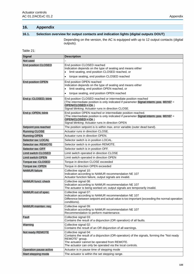
16. Appendix
16.1. Selection overview for output contacts and indication lights (digital outputs DOUT)
Depending on the version, the AC is equipped with up to 12 output contacts (digitaloutputs).
Table 21:
DescriptionSignal–Not usedEnd position CLOSED reachedIndication depends on the type of seating and means either● limit seating, end position CLOSED reached, or
● torque seating, end position CLOSED reached
End position CLOSED
End position OPEN reachedIndication depends on the type of seating and means either● limit seating, end position OPEN reached, or
● torque seating, end position OPEN reached
End position OPEN
End position CLOSED reached or intermediate position reached(The intermediate position is only indicated if parameter Signal interm. pos. M0167 =OPEN/CLOSED = On.)Signal blinking: Actuator runs in direction CLOSE.
End p. CLOSED, blink
End position OPEN reached or intermediate position reached.(The intermediate position is only indicated if parameter Signal interm. pos. M0167 =OPEN/CLOSED = On.)Signal blinking: Actuator runs in direction OPEN
End p. OPEN, blink
The position setpoint is is within max. error variable (outer dead band).Setpoint pos.reachedActuator runs in direction CLOSE.Running CLOSEActuator runs in direction OPEN.Running OPENSelector switch is in position LOCAL.Selector sw. LOCALSelector switch is in position REMOTE.Selector sw. REMOTESelector switch is in position OFF.Selector sw. OFFLimit switch operated in direction CLOSELimit switch CLOSEDLimit switch operated in direction OPENLimit switch OPENTorque in direction CLOSE exceededTorque sw. CLOSEDTorque in direction OPEN exceededTorque sw. OPENCollective signal 10:Indication according to NAMUR recommendation NE 107Actuator function failure, output signals are invalid.
NAMUR failure
Collective signal 08:Indication according to NAMUR recommendation NE 107The actuator is being worked on; output signals are temporarily invalid.
NAMUR funct. check
Collective signal 07:Indication according to NAMUR recommendation NE 107Difference between setpoint and actual value is too important (exceeding the normal operationconditions).
NAMUR out of spec.
Collective signal 09:Indication according to NAMUR recommendation NE 107Recommendation to perform maintenance.
NAMUR mainten. req.
Collective signal 03:Contains the result of a disjunction (OR operation) of all faults.
Fault
Collective signal 02:Contains the result of an OR disjunction of all warnings.
Warning
Collective signal 04:Contains the result of a disjunction (OR-operation) of the signals, forming the "Not readyREMOTE" group.The actuator cannot be operated from REMOTE.The actuator can only be operated via the local controls.
Not ready REMOTE
Actuator is in pause time of stepping modeOperation pause activeThe actuator is within the set stepping range.Start stepping mode
133
Actuator controls AC 01.2/ACExC 01.2 Appendix

DescriptionSignalActuator is running (output drive is moving)Hard wired collective signal consisting of:● Running LOCAL● Running REMOTE● Handwheel oper.
Actuator running
Output drive rotates due to operation command from LOCAL.Running LOCALOutput drive rotates due to operation command from REMOTE.Running REMOTEOutput drive rotates without electric operation command.Handwheel oper.The actuator is in an intermediate position e.g. neither in end position OPEN nor in end pos-ition CLOSED.
In intermediate pos.
Intermediate position 1 reachedIntermediate pos. 1Intermediate position 2 reachedIntermediate pos. 2Intermediate position 3 reachedIntermediate pos. 3Intermediate position 4 reachedIntermediate pos. 4Intermediate position 5 reachedIntermediate pos. 5Intermediate position 6 reachedIntermediate pos. 6Intermediate position 7 reachedIntermediate pos. 7Intermediate position 8 reachedIntermediate pos. 8A high signal (+24 V DC) is present at digital input 1.Input DIN 1A high signal (+24 V DC) is present at digital input 2.Input DIN 2A high signal (+24 V DC) is present at digital input 3.Input DIN 3A high signal (+24 V DC) is present at digital input 4.Input DIN 4A high signal (+24 V DC) is present at digital input 5.Input DIN 5A high signal (+24 V DC) is present at digital input 6.Input DIN 6Operation mode EMERGENCY stop is active (EMERGENCY stop button has been pressed).EMCY stop activeTorque fault in direction CLOSETorque fault CLOSETorque fault in direction OPENTorque fault OPENTorque fault in directions CLOSE or OPENTorque faultMotor protection trippedThermal faultOne phase missingPhase faultManual operation is active (handwheel is engaged); optional signal.Handwheel activePartial Valve Stroke Test (PVST) is active.PVST activePartial Valve Stroke Test (PVST) could not be successfully completed.PVST faultPartial Valve Stroke Test (PVST) was aborted or could not be started. Remedy: PerformRESET or restart PVST.
PVST abort
This signal can be configured (parameter Failure (configurable) M0879) and comprises acombination of the following signals which can also be configured:● Fault (Cfg) M0880● Warnings (Cfg) M0881● Not ready REMOTE (Cfg) M0882
Failure (configurable)
Function Interlock is active for operation mode REMOTE.Interlock RemoteFunction Interlock is active for operation mode Local.Interlock LocalInterlock OPEN is active (enable signal for operation commands in direction OPEN available).Interlock OPENInterlock CLOSED is active (enable signal for operation commands in direction CLOSEavailable).
Interlock CLOSE
The operation mode Interlock is active.Interlock<By-pass function> enable for operation commands of main or by-pass valves is active.Bypass Sync OutOperation command executed without enable signal Bypass Sync Out.Interlock by-passSafe ESD function (Emergency Shut Down) is active.Safe ESDSafe STOP function is active.Safe StopA SIL fault has occurred (collective signal).SIL faultA SIL function is active. Collective signal of both states, Safe ESD or Safe STOP.SIL function activeThe actuator is switched on and no fault is presentSystem ok
134
Actuator controlsAppendix AC 01.2/ACExC 01.2

DescriptionSignalTorque wrn OPENTorque wrn CLOSE
LPV (Lift Plug Valve) synchronisation signal. Master or slave actuator are in an end position.LPV Sync OutOperation command in direction OPEN from the master actuator to the slave actuator (SA).LPV SA-OPENOperation command in direction CLOSE from the master actuator to the slave actuator (SA).LPV SA-CLOSE(PVST) Partial Valve Stroke Test should be executedPVST requiredFQM (fail safe) readyFQM FS readyThe fail safe function of the FQM (Fail safe) is active.FQM requestFQM has reached end position OPEN at the output drive side.FQM end pos. openFQM has reached end position CLOSED at the output drive side.FQM end pos. closed
16.2. Selection overview of binary signals for digital inputs (DIN)
Depending on the version, the AC is equipped with up to 10 digital inputs.
The inputs are designed for binary signals (standard input level: +24 V DC) and canbe used, for example, to receive operation commands OPEN, STOP, CLOSE, tocontrol intermediate positions or for the EMERGENCY signal.
Configuration of digital inputs
Required user level: Specialist (4).
Device configuration M0053I/O interface M0139Digital inputs M0116
Table 22:
DescriptionSignalInput not assignedNot usedChange-over between OPEN - CLOSE control and setpoint controlMODEOperation command OPENOPENOperation command CLOSECLOSEOperation command STOPSTOPReset fault signalRESETChange-over between fieldbus interface and parallel interfaceI/O interfaceOperation command OPEN/CLOSE for two-wire controlOPEN / CLOSEOperation mode for EMERGENCY behaviourEMERGENCYOperation command: Run to intermediate position 1.Intermediate pos. 1Operation command: Run to intermediate position 2.Intermediate pos. 2Operation command: Run to intermediate position 3.Intermediate pos. 3Operation command: Run to intermediate position 4.Intermediate pos. 4Operation command: Run to intermediate position 5.Intermediate pos. 5Operation command: Run to intermediate position 6.Intermediate pos. 6Operation command: Run to intermediate position 7.Intermediate pos. 7Operation command: Run to intermediate position 8.Intermediate pos. 8Operation command: Run to intermediate position 9.Intermediate pos. 9Operation command: Run to intermediate position 10.Intermediate pos. 10Operation command: Run to intermediate position 11.Intermediate pos. 11Operation command: Run to intermediate position 12.Intermediate pos. 12Clockwise approach of position 1MPV: CW Position 1Counterclockwise approach of position 1MPV: CCW Position 1Clockwise approach of position 2MPV: CW Position 2Counterclockwise approach of position 2MPV: CCW Position 2Clockwise approach of position 3MPV: CW Position 3Counterclockwise approach of position 3MPV: CCW Position 3
135
Actuator controls AC 01.2/ACExC 01.2 Appendix

DescriptionSignalClockwise approach of position 4MPV: CW Position 4Counterclockwise approach of position 4MPV: CCW Position 4Clockwise actuator operationMPV DriveCWCounterclockwise actuator operationMPV DriveCCWSignal for controlling output contactInput DIN 1Signal for controlling output contactInput DIN 2Signal for controlling output contactInput DIN 3Signal for controlling output contactInput DIN 4Enables the selector switch function (LOCAL/OFF) on the local controlsEnable LocalInterlock: Enables operation command in direction OPENEnable OPENInterlock: Enables operation command in direction CLOSEEnable CLOSEInternal PID setpointPID internal setpoint 2Activation of operation mode Remote IIRemote2_activeOperation command OPEN in operation mode Remote IIRemote2_OPENOperation command CLOSE in operation mode Remote IIRemote_2_CLOSEOperation command STOP in operation mode Remote IIRemote2_STOPPVST is executedExecute PVSTEnable signal for <By-pass function>Bypass Sync InEnable signal for LPV function (synchronisation)LPV Sync InLPV slave actuator has reached end position CLOSEDLPV end position CLSelector switch of LPV slave actuator is in position REMOTELPV sel.sw.RemoteLPV slave actuator is ready for operationLPV system okChange-over of process controller setpoint source between fieldbus interface and I/O interfacePID setpoint I/OChange-over of process controller actual value source between fieldbus interface and I/Ointerface
PID act. value I/O
136
Actuator controlsAppendix AC 01.2/ACExC 01.2

Index
AAcceleration (histogram) 121Acceleration-frequency (histo-gram)
121
Activate/deactivate heater 76Activate functions 102Actual configuration 106Actual value - indication ondisplay
21
Actual value source - processcontroller
60
Actuator controls heater sys-tem
76
Actuator controls terminalplan
10
Actuator operation at the localcontrols
13
Actuator operation from re-mote
14
Actuator terminal plan 10Actuator type (MPV) 69Adaptive behaviour 50Ambient temperature 10Analogue output 1 29Analogue output 1 adjustment 30Analogue output 1 signalrange
30
Analogue output 2 30Analogue output 2 adjustment 31Analogue output 2 signalrange
30
Analogue outputs 29Analogue signals 29Appendix 133Application functions 46Automatic deblocking 74
BBacklash compensation(MPV)
72
Basic settings 37Binary input signals 135Bluetooth 106Bluetooth diagnostic 108By-pass function 62
CCDT 106 , 106Change-over between OPEN- CLOSE control and setpointcontrol
53
Characteristics 116 , 116 , 118 , 119Closing fully/opening fully 52Commissioning 8Commissioning (indicationson display)
19
Configurable signals 27Contrast 45Control 10 , 11 , 33Controller behaviour (processcontroller)
56
Control voltage 11Correction of the direction ofrotation
101
Corrective action 125Cycles 95
DData export 105Data import 105Data Matrix code 11Date 42Date format 42Deactivate heater monitoringwithin actuator controls
100
Dead band 51 , 51Dead band (MPV) 72Dead time 52Delay time 79Delay time <EMERGENCYoperation>
84
Device temperatures 124Device type 10Diagnostic Interface 109Diagnostics 108Digital inputs 135 , 135Digital inputs (diagnostics) 109Digital outputs 27Digital outputs (diagnostics) 109Direct display via ID 15Direction of rotation 101 , 104Direction of rotation: 104Directives 8Display (indications) 19Display formats 42Display operating time 124Down time 101
137
Actuator controls AC 01.2/ACExC 01.2 Index

EElectronic device ID 108Electronics monitoring powersupply
98
EMERGENCY behaviour 79EMERGENCY operation 79 , 81EMERGENGY stop 35Enable functions 102Enable operation commands 86Enabling local controls 84Enclosure protection 10End position seating 37End position tolerance 52Enforce REMOTE control 85Error - indication on display 19Error variable 51Event report 115
FFactory setting 104Fail safe (diagnostic) 112Failure behaviour 77Failure functions 77Failure - indication on display 25Failure operation 77Failure position 78Failure source (EMERGENCYoperation)
81
Failure source (failure opera-tion)
77
Failure source (Interlock) 87Fault - indication on display 23Fault signal - configurable 27Firmware update 106Firmware version 106FQM (diagnostics) 112Frequency (histogram) 121Function check - indication ondisplay
24
Functions: activate/enable 102Fuses 125
GGear reduction ratio 69
HHeater 99Heater in switch compartment 76Heater monitoring 99Heater monitoring time 100Heater on control unit 76Heater system 99Heater system monitoring 99Histogram 119 , 120 , 121 , 121Histograms 119Home port 70
IIdentification 10Indication light colour 26Indication lights 25Indications 19Indications on display 19Input current 11Input signal 11Inspection certificate 10Interface (diagnostics) 109Interlock: 86Interlock: by-pass 83Interlock behaviour 87Intermediate position indica-tion via LEDs
25
Intermediate positions 46Internal process setpoint 58Intrusive 12Inverse operation 58
LLanguage in the display 17LEDs (indication lights) 25Lift Plug Valve 64Limit seating 37Limit setting range 53Limit switching 40Local actuator operation 13Local control 13Local controls 13Local setting 14Local Stop 88Local stop: by-pass 83Loss of process setpoint 58Loss of signal 77 , 78Loss of signal process set-point
58
LPV 64
138
Actuator controlsIndex AC 01.2/ACExC 01.2

MMain menu 15Mains voltage 10Maintenance 8Maintenance required - indic-ation on display
24
Maintenance signals 122Menu navigation 14MODE 53Monitoring functions 93Motion detector 97Motor heater 76Motor protection. by-pass 82Motor protection behaviour 94Motor protection monitoring 94 , 94Motor running time positionhistogram
119
Motor running time-temperat-ure (histogram)
120
Motor running time-torque(histogram)
121
Motor starts 95Multiport valve function 68Multiport valve positions – in-dication on display
22
MWG (diagnostic) 111
NName plate 10Non-Intrusive 12Not ready REMOTE - indica-tion on display
23
Number format 43 , 43Number of ports (positions) 69
OOff time 49 , 61On time 61 , 95On time monitoring (dia-gnostics)
111
OPEN - CLOSE control (Re-mote OPEN - CLOSE)
53
Operating data 114Operation 8 , 13 , 32Operation commands - indic-ations on display
21
Operation profile 48Operation profile: by-pass 83Operation time monitoring 96Order number 10 , 10Out of specification - indica-tion on display
24
Output contacts 27Output signals 27Overload protection 93Overrun 51
PPartial Valve Stroke Test 89Password 16Password change 17Password entry 16Permissible operation time 96Permissible starts/h 96Phase failure monitoring 101Phase sequence detection 101Plant Asset Management 114Positioner 50Positioner (diagnostic) 111Positioner - indication on dis-play
22
Positions (pivot points) 46Positions – indication on dis-play
22
Position-time characteristic 118Position transmitter (diagnost-ic)
110
Position unit 43Potentiometer (diagnostic) 110Power class 10Power class for switchgear 11Primary fuses 125Priority REMOTE 85Process controller 55Process controller (dia-gnostics)
112
Process factor unit 44Process setpoint – loss 58Production, year 11Proportional amplification Kp 59Protective measures 8Push-to-run operation local 32Push-to-run operation Re-mote
33
PVST 89
QQualification of staff 8
RRate time Td 59Reaction monitoring 97Reaction time 97Reaction time, permissible 97Reaction time of heater mon-itoring
100
Remote actuator operation 14Reset time Tn 59Reversing prevention time 77Running time 95Running time (motor) 119 , 120 , 121RWG (diagnostic) 110
139
Actuator controls AC 01.2/ACExC 01.2 Index

SSafety instructions 8Safety instructions/warnings 8Selection overview for outputcontacts and indication lights
133
Selector switch functions 84Self-retaining local 32Self-retaining Remote 33Serial number 10 , 11Service 35Service functions 104Setpoint - indication on dis-play
22
Setpoint source - processcontroller
57
Signal behaviour (multiportvalve)
73
Signal loss 78Signal output units (AIN) 45Signals 27Signals (analogue) 29Signals - configurable 27Simulation 112Size 10Sollwertansteuerung (FernSOLL)
53
Split Range operation 54Standards 8Start of stepping mode 61Status menu 15Status signals 27Status signals - configurable 27Stepping mode 60Stepping mode: by-pass 83Stop step 61Support App 11 , 11Switching off for reaction timeerror
97
TTarget configuration 106Temperature (motor) 120Temperature indication 124Temperature monitoring 99Temperature-time character-istic
119
Temperature unit 43Thermal monitoring 94Time 42Torque (histogram) 121Torque by-pass 93 , 93Torque - indication on display 21Torque monitoring 93Torque seating 37Torque switching 38 , 39Torque switching: by-pass 82Torque-travel characteristic 116Torque unit 43Torque warning 93Two-wire control 49Type (device type) 10Type designation 10Type of seating for end posi-tions
37
UUser level 16
VValve position - indication ondisplay
20
Verification of sub-assemblies 100
WWarnings - indication on dis-play
23
Wiring diagram 10Working value units (AIN) 45
YYear of production 11
140
Actuator controlsIndex AC 01.2/ACExC 01.2

Parameter index
00/4 mA (initial value) 31
220 mA (final value) 3124 V DC customer 13024 V DC external 12624 V DC internal 131
AAbs. end pos. CLOSED 111Abs. end pos. OPEN 111Absolute value 111Accept actual config. 106Activation 44 , 44 , 45 , 45Actual position 29 , 111Actual process value 112Actuator behaviour 97Actuator type 69Adapt rotary dir. 101Adjustment AOUT 1 30Adjustment AOUT 2 31
BBacklash comp. 72Bluetooth add.partner 107 , 109Bluetooth address 107 , 109Buffer size 116By-pass application 64By-pass Interlock 83By-pass Local STOP 83By-pass operat.profile 83By-pass timer 83By-pass torque 82
CCalibration 132Change passwords 17Closing rotation 104Coding DOUT 1 27Colour ind.light 1 26Colour ind.light 2 26Colour ind.light 3 26Colour ind.light 4 26Colour ind.light 5 26Command fieldbus 130Config. error REMOTE 127 , 127 , 131Config. operat. profile 129Config. PID controller 129Config. warning 126 , 126 , 128Configuration EMCY 129Configuration error 127 , 127 , 129Create factory settings 105
DDate and time 42Dead band CLOSE 51Dead band OPEN 51Deblocking attempts 75Delay MA direct.CLOSE 67Delay MA direct.OPEN 67Delay SA direct.CLOSE 68Detect. time dt 98Detect. time dt (MWG) 98Device ID 108Device tag 107 , 109DIN 1 configuration 129Disabled 128
EEMCY behav. active 128EMCY failure source 81EMCY operation 81EMCY operation mode 81EMCY position 82EMCY position MPV 82EMCY stop active 128End position CLOSED 37End position OPEN 37End stepping CLOSE 61End stepping OPEN 61Event filter for Events 115Export all data 105Export all parameters 105Export event report 105
FFail.beh. config. 129Fail.pos.OPEN CLOSE 78Failure 125Failure (configurable) 28Failure beh. source 77Failure behav. active 126Failure position MPV 79Failure reaction EMCY 80Fault 125Fault (Cfg) 28Fault no reaction 128File size 115Firmware 106FO cables 112FO configuration 129FQM fail safe end.pos. 112FQM FS diag. result 112FQM FS-PosOk 112FQM FS ready 112FQM request 112FQM timeout tension 112Function check 125
141
Actuator controls AC 01.2/ACExC 01.2 Parameter index

HHandwheel active 128Heat.monitor.config. 129Heater control unit 76Heater monitor 100Heating sys. mon. time 100High limit AIN 1 54High limit target value 55Hydraulics fault 129Hydraulics warning 131Hysteresis 48 , 74Hysteresis 1 48
II/O interface 128IE 24 V AC 130IE bus exception 130IE config. pos. transm. 129IE EEPROM 130IE fieldbus 130IE file access 130IE Hall 1 calibration 130IE Hall 5 calibration 130IE I/O interface 131IE LC 130IE LC exception 130IE logic 130IE logic exception 130IE MCM 129IE mot. prot. monitor 130IE MWG 130IE MWG calibration 130IE MWG end positions 130IE MWG exception 130IE output defective 130IE parameter 130IE parameter config. 129IE phase monitoring 130IE position transmitter 130IE PSO 129IE registration 130IE remote interface 131IE remote Prm Config 131IE reserve backup 130IE selector switch 130IE startup FB 130IE startup sub-assy 130IE version 130Import all parameters 106Incorr. cmd REMOTE1 129Incorr. cmd REMOTE2 129Incorrect phase seq 127 , 129Indicat. light 5 (right) 25Indication light 1 (left) 25Indication light 2 25Indication light 3 25Indication light 4 25Inner dead b. CLOSE 111Inner dead b. OPEN 111Input AIN 1 29Input AIN 2 29Input of setpoint position 54Interface 109Interface status 109Interlock 87 , 128Interlock by-pass 128Interlock failure source 87Internal error 127 , 127 , 130Internal warning 126 , 126 , 130Interval position-time 119Invalid command 132
142
Actuator controlsParameter index AC 01.2/ACExC 01.2

LLanguage 17Limit CLOSE 53Limit OPEN 53Limit starts CLOSE 124Limit starts OPEN 124Limit turns CLOSE 124Limit turns OPEN 124Local STOP 88Low limit AIN 1 54Low limit RWG 111Low limit target value 55Low limit Uspan 110LPV application 67LPV function 67
MMains quality 128Maintenance interval 122 , 123Maintenance required 125Max. value at 100.0 % 44 , 44 , 45 , 45Maximum stroke 111Minimum stroke 111Modulating behaviour 57Monitor 24 V DC cust. 99Monitor 24 V DC ext. 99Monitor heat. system 100Motor running time 129MPV function 69 , 75MPV home port 70
NNot ready REMOTE 125Not ready REMOTE (Cfg) 28Not referenced 132Number of ports 69
OOff time 1 49Off time CLOSE 61Off time OPEN 62Off times 49Oil leakage 129Oil level 129On time/h 112On time CLOSE 61On time monitoring 96 , 111On time OPEN 62On time warning 1 95On time warning 2 95Op. com. PID contr. 112Op. time warning 126Oper. mode Interlock 87Oper. press. config. 131Oper. time monitoring 96 , 96Oper. time opposite 75Operat. pressure min 131Operating time 124Operational info 114 , 114 , 114Operational info total 114Operation behaviour 48Operation behaviour 1 48Operation mode 96Outer dead b. CLOSE 111Outer dead b. OPEN 111Outer dead band 52Out of range 132Out of specification 125
143
Actuator controls AC 01.2/ACExC 01.2 Parameter index

PPCB failure 132Perm.op. time, manual 96Perm. running time/h 96Phase fault 127 , 129Phase monitoring 101Pivot point 1 46Position 44 , 44Positioner hyst. CLOSE 52Positioner hyst. OPEN 52Position-time 118Position transm. MWG 111Position transm. potent. 110Position transm. RWG 111Potent. raw value /mV 110Pressure rise 129Process factor 44 , 44Process setpoint 112Pump starts 131PVST abort 126PVST active 128PVST behaviour 91PVST fault 126PVST monitoring 91PVST operating time 91PVST operation mode 90PVST reminder 92PVST reminder period 92PVST reversing time 91PVST stroke 91
RRaw val. pos. CLOSED 110 , 111Raw val. pos. OPEN 110 , 111Reduction ratio 69 , 72Reload languages 105Replacement value 132Reset characteristic 117Reset factory settings 105Reset operation. info 114Revers. prevent. time 77RTC voltage 126Running dir. Interlock 88RWG raw value /mA 111
SSave interval 116Scaling 44 , 44 , 45 , 45Sel. sw. not REMOTE 128Self-retaining 33Self-retaining Local 32Self-retaining Remote II 33Sensor failure 132Service active 128Set end pos.CLOSED? 40Set end pos. OPEN? 40Setpoint pos. disabled 130Setpoint position 111Setpoint position - input 54Signal AIN 1 54Signal AIN 2 54Signal AOUT 1 29Signal AOUT 2 30Signal behaviour 46 , 73Signal behaviour 1 46Signal DOUT 1 27 , 113Signal interm. pos. 25Signal loss beh. 77Signal outputs (AIN) 45 , 45Signal range AOUT1 30Signal range AOUT2 30Speed target value 30Split range operation 55Starts/h 112Start stepping CLOSE 61Start stepping OPEN 61States AIN 1 109States AIN 2 109States AOUT 1 109States AOUT 2 109States DIN 109States DOUT 109Step mode CLOSE 61Step mode OPEN 61Switchgear 77System event filter 115
144
Actuator controlsParameter index AC 01.2/ACExC 01.2

TTemperature-time 119Thermal by-pass 82Thermal fault 128 , 129Time format 43Time not set 126Timer CLOSE 61Timer OPEN 61Tolerance CLOSE 52Tolerance OPEN 52Tolerance range 75Torque 29Torque by-pass [s] 94Torque config. CLOSE 128Torque config. OPEN 129Torque fault CLOSE 127Torque fault OPEN 127Torque-travel 116 , 117 , 117 , 118Torque wrn CLOSE 127Torque wrn OPEN 127Travel diff. dx 98Travel diff. dx (MWG) 98Tripping time 101Trip torque CLOSE 39Trip torque OPEN 39Type of seating 37
UUnit 44 , 44 , 45 , 45Units 44 , 44 , 44 , 44
, 45 , 45 , 45 ,45
Update firmware 106
VVersion 108Volt.level diff. potent. 110
WWarnings 125Warnings (Cfg) 28Working values (AIN) 45 , 45Wrn controls temp. 126Wrn Dead bands 128Wrn event mark 131Wrn FOC 126Wrn FO cable budget 126Wrn FOC connection 127Wrn gearbox temp. 126Wrn heater 130Wrn input AIN 1 126Wrn input AIN 2 126Wrn motor temp. 126Wrnn no reaction 126Wrn on time running 126Wrn on time starts 126Wrn range act.pos. 131Wrn ref.actual position 131Wrn res. data in use 131Wrn setpoint position 126Wrn Setpoint Source 128Wrn sign.loss act.pos. 131Wrn Tm mark 131Wrn torque CLOSE 93Wrn torque OPEN 93Wrong oper. cmd 128 , 129
145
Actuator controls AC 01.2/ACExC 01.2 Parameter index

Europe
AUMA Riester GmbH & Co. KG
Location MuellheimDE 79373 MuellheimTel +49 7631 809 - [email protected]
Location Ostfildern-NellingenDE 73747 OstfildernTel +49 711 34803 - [email protected]
Service-Center BayernDE 85386 EchingTel +49 81 65 9017- [email protected]
Service-Center KölnDE 50858 KölnTel +49 2234 2037 - [email protected]
Service Center MagdeburgDE 39167 NiederndodelebenTel +49 39204 759 - [email protected]
AUMA-Armaturenantriebe Ges.m.b.H.AT 2512 TribuswinkelTel +43 2252 [email protected]
AUMA BENELUX B.V. B. A.BE 8800 RoeselareTel +32 51 24 24 [email protected]
ProStream Group Ltd.BG 1632 SofiaTel +359 2 [email protected]
OOO “Dunkan-Privod”BY 220004 MinskTel +375 29 [email protected]
AUMA (Schweiz) AGCH 8965 BerikonTel +41 566 [email protected]
AUMA Servopohony spol. s.r.o.CZ 250 01 Brandýs n.L.-St.BoleslavTel +420 326 396 [email protected]
GRØNBECH & SØNNER A/SDK 2450 København SVTel +45 33 26 63 [email protected]
IBEROPLAN S.A.ES 28027 MadridTel +34 91 [email protected]
AUMA Finland OyFI 02230 EspooTel +358 9 5840 [email protected]
AUMA France S.A.R.L.FR 95157 Taverny CedexTel +33 1 [email protected]
AUMA ACTUATORS Ltd.GB Clevedon, North Somerset BS21 6THTel +44 1275 [email protected]
D. G. Bellos & Co. O.E.GR 13673 Acharnai, AthensTel +30 210 [email protected]
APIS CENTAR d. o. o.HR 10437 BestovjeTel +385 1 6531 [email protected]
Fabo Kereskedelmi és Szolgáltató Kft.HU 8800 NagykanizsaTel +36 93/[email protected]
Falkinn HFIS 108 ReykjavikTel +00354 540 [email protected]
AUMA ITALIANA S.r.l. a socio unicoIT 20023 Cerro Maggiore (MI)Tel +39 0331 [email protected]
AUMA BENELUX B.V.LU Leiden (NL)Tel +31 71 581 40 [email protected]
NB Engineering ServicesMT ZBR 08 ZabbarTel + 356 2169 [email protected]
AUMA BENELUX B.V.NL 2314 XT LeidenTel +31 71 581 40 [email protected]
SIGUM A. S.NO 1338 SandvikaTel +47 [email protected]
AUMA Polska Sp. z o.o.PL 41-219 SosnowiecTel +48 32 783 52 [email protected]
AUMA-LUSA Representative Office, Lda.PT 2730-033 BarcarenaTel +351 211 307 [email protected]
SAUTECHRO 011783 BucurestiTel +40 372 [email protected]
OOO PRIWODY AUMARU 141402 Khimki, Moscow regionTel +7 495 221 64 [email protected]
OOO PRIWODY AUMARU 125362 MoscowTel +7 495 787 78 [email protected]
ERICHS ARMATUR ABSE 20039 MalmöTel +46 40 [email protected]
ELSO-b, s.r.o.SK 94901 NitraTel +421 905/[email protected]
Auma Endüstri Kontrol Sistemleri LimitedSirketiTR 06810 AnkaraTel +90 312 217 32 [email protected]
AUMA Technology Automations LtdUA 02099 KievTel +38 044 [email protected]
Africa
Solution Technique Contrôle CommandeDZ Bir Mourad Rais, AlgiersTel +213 21 56 42 09/[email protected]
A.T.E.C.EG CairoTel +20 2 23599680 - [email protected]
SAMIREGMA 203000 CasablancaTel +212 5 22 40 09 [email protected]
MANZ INCORPORATED LTD.NG Port HarcourtTel [email protected]
146
AUMA worldwide

AUMA South Africa (Pty) Ltd.ZA 1560 SpringsTel +27 11 [email protected]
America
AUMA Argentina Rep.OfficeAR Buenos AiresTel +54 11 4737 [email protected]
AUMA Automação do Brazil ltda.BR Sao PauloTel +55 11 [email protected]
TROY-ONTOR Inc.CA L4N 8X1 Barrie, OntarioTel +1 705 [email protected]
AUMA Chile Representative OfficeCL 7870163 SantiagoTel +56 2 2821 [email protected]
B & C Biosciences Ltda.CO Bogotá D.C.Tel +57 1 349 [email protected]
AUMA Región Andina & CentroaméricaEC QuitoTel +593 2 245 [email protected]
Corsusa International S.A.C.PE Miraflores - LimaTel +511444-1200 / 0044 / [email protected]
Control Technologies LimitedTT Marabella,Trinidad, W.I.Tel + 1 868 658 1744/5011www.ctltech.com
AUMA ACTUATORS INC.US PA 15317 CanonsburgTel +1 724-743-AUMA (2862)[email protected]
SuplibarcaVE Maracaibo, Estado, ZuliaTel +58 261 7 555 [email protected]
Asia
AUMA Actuators UAE Support OfficeAE 287 Abu DhabiTel +971 [email protected]
AUMA Actuators Middle EastBH 152 68 SalmabadTel +97 3 [email protected]
Mikuni (B) Sdn. Bhd.BN KA1189 Kuala BelaitTel + 673 3331269 / [email protected]
AUMA Actuators (China) Co., Ltd.CN 215499 TaicangTel +86 512 3302 [email protected]
PERFECT CONTROLS Ltd.HK Tsuen Wan, KowloonTel +852 2493 [email protected]
PT. Carakamas Inti AlamID 11460 JakartaTel +62 [email protected]
AUMA INDIA PRIVATE LIMITED.IN 560 058 BangaloreTel +91 80 2839 [email protected]
ITG - Iranians Torque GeneratorIR 13998-34411 [email protected]
Trans-Jordan Electro Mechanical SuppliesJO 11133 AmmanTel +962 - 6 - [email protected]
AUMA JAPAN Co., Ltd.JP 211-0016 Kawasaki-shi, KanagawaTel +81-(0)[email protected]
DW Controls Co., Ltd.KR 153-702 Gasan-dong, GeumChun-Gu,,SeoulTel +82 2 2624 [email protected]
Al-Arfaj Engineering Co WLLKW 22004 SalmiyahTel [email protected]
TOO “Armaturny Center”KZ 060005 AtyrauTel +7 7122 454 [email protected]
Network EngineeringLB 4501 7401 JBEIL, BeirutTel +961 9 [email protected]
AUMA Malaysia OfficeMY 70300 Seremban, Negeri SembilanTel +606 633 [email protected]
Mustafa Sultan Science & Industry Co LLCOM RuwiTel +968 24 [email protected]
FLOWTORK TECHNOLOGIESCORPORATIONPH 1550 Mandaluyong CityTel +63 2 532 [email protected]
M & C Group of CompaniesPK 54000 Cavalry Ground, Lahore CanttTel +92 42 3665 0542, +92 42 3668 [email protected]
Petrogulf W.L.LQA DohaTel +974 [email protected]
AUMA Saudi Arabia Support OfficeSA 31952 Al KhobarTel + 966 5 5359 [email protected]
AUMA ACTUATORS (Singapore) Pte Ltd.SG 569551 SingaporeTel +65 6 [email protected]
NETWORK ENGINEERINGSY Homs+963 31 231 [email protected]
Sunny Valves and Intertrade Corp. Ltd.TH 10120 Yannawa, BangkokTel +66 2 [email protected]
Top Advance Enterprises Ltd.TW Jhonghe City,Taipei Hsien (235)Tel +886 2 2225 [email protected]
AUMA Vietnam Hanoi ROVN Hanoi+84 4 [email protected]
Australia
BARRON GJM Pty. Ltd.AU NSW 1570 ArtarmonTel +61 2 8437 [email protected]
147
AUMA worldwide

AUMA Riester GmbH & Co. KG
P.O. Box 1362DE 79373 MuellheimTel +49 7631 809 - 0Fax +49 7631 809 - [email protected]
Y004.735/003/en/1.15
For detailed information on AUMA products, refer to the Internet: www.auma.com