actuator controls aumatic ac 01.1/acexc 01 · devicenet → foundation fieldbus ... actuator...
TRANSCRIPT

Control
Parallel
Profibus DP
Modbus
DeviceNet
→ Foundation Fieldbus
Actuator controls
AUMATIC AC 01.1/ACExC 01.1
Operation and settingManual

Read operation instructions first.● Observe safety instructions.
Purpose of the document:
This document contains information for the commissioning, operation and maintenance staff. It is intended tosupport local device operation and setting modifications.
Reference documents:● Operation instructions (Assembly, operation, commissioning) for actuator.● Manual (Device integration Fieldbus) AUMATIC AC 01.1/ACExC 01.1 Foundation Fieldbus
Reference documents can be downloaded from the Internet (www.auma.com) or ordered directly from AUMA(refer to <Addresses>).
Table of contents Page
61. Safety instructions.................................................................................................................61.1. Basic information on safety61.2. Range of application71.3. Warnings and notes71.4. References and symbols
92. Identification...........................................................................................................................92.1. Name plate92.2. Short description
113. Operation................................................................................................................................113.1. Local operation123.2. Operation from REMOTE123.3. Menu navigation via push buttons (for settings and indications)133.3.1 Short overview: Functions of the push buttons133.3.2 Structural design and navigation143.4. Password entry143.5. Password change153.6. Operation and setting via AUMA programming software COM-AC163.6.1 Setting operation via COM-AC
174. Indications..............................................................................................................................174.1. Language change in the display174.2. Status indications in the display174.2.1 Status indication S0/S6 - operation184.2.2 Status indication S4 - torque184.2.3 Torque indication: edit194.3. Electronic name plate194.3.1 Enable viewing194.3.2 Electronic name plate: view204.4. Indication lights/LEDs214.4.1 Configuration of signals: view/edit214.4.2 Blinking behaviour of indication lights/LEDs: view/edit
235. Signals.....................................................................................................................................235.1. Signals via fieldbus235.1.1 Configuration of customisable (user-definable) signals235.2. Feedback signals via output contacts (binary)
2
Actuator controlsTable of contents AUMATIC AC 01.1/ACExC 01.1 Foundation Fieldbus

235.2.1 Configuration for output contacts 1 to 5: view/edit255.2.2 Configuration for alarm contacts (collective fault signal): view/edit265.2.3 Output contacts 1 to 5: use as running indication (blinker)275.3. Feedback signals (analogue)275.3.1 Position transmitter/actual position source (E2): view275.3.2 Source of the torque signal E6: view285.3.3 Feedback signals (configuration) via analogue output 1: view295.3.4 Signal range at the analogue output 1: view/edit295.3.5 Feedback signals (configuration) via analogue output 2: view305.3.6 Signal range at the analogue output 2: view/edit
316. Operation ...............................................................................................................................316.1. Operation mode OFF316.2. Operation mode LOCAL316.2.1 Push-to-run operation or self-retaining: set for the operation mode LOCAL326.3. Operation mode REMOTE336.3.1 Push-to-run operation or self-retaining: set for operation mode REMOTE336.4. Operation mode EMERGENCY346.4.1 Operation mode: activate for EMERGENCY operation346.4.2 EMERGENCY operation: enable/disable/signal behaviour definition356.4.3 Actuator behaviour definition in case of an emergency operation356.4.4 EMERGENCY position definition366.4.5 Motor protection and/or torque switching by-pass366.5. Failure behaviour on loss of signal376.5.1 Failure behaviour enable/disable376.5.2 Source for initiation (failure source): set for failure operation386.5.3 Actuator reaction (failure position): setting on loss of signal386.5.4 Preset position: define396.5.5 Failure delay time setting
407. Functions and settings..........................................................................................................407.1. Type of seating: check/edit for end positions407.2. Torque switching: check/set417.3. Limit switching: set427.4. Intermediate positions427.4.1 Display indication: enable view437.4.2 Intermediate positions: activate/deactivate437.4.3 Intermediate position definition437.4.4 Operation behaviour = actuator behaviour definition447.4.5 Signalling of intermediate positions: set457.5. Intermediate positions with multiport valve function457.5.1 Check: Multiport valve function available?467.5.2 Positioner: activate (Check: Positioner available?)467.5.3 Display indication: enable view467.5.4 Intermediate positions activate/deactivate477.5.5 Intermediate position definition477.5.6 Operation behaviour = actuator behaviour definition477.5.7 Intermediate positions: set the signalling477.5.8 Intermediate positions in LOCAL: direct approach without stopping487.6. Positioner (SETPOINT MODE operation mode)497.6.1 Positioner: activate (Check: Positioner available?)
3
Actuator controlsAUMATIC AC 01.1/ACExC 01.1 Foundation Fieldbus Table of contents

497.6.2 Adaptive behaviour: activate/deactivate507.6.3 Overrun (inner dead band): manual setting517.6.4 Max. error variable (outer dead band): manual setting517.6.5 Dead time: set517.6.6 Closing fully/opening fully (end position tolerance for setpoint E1)527.6.7 Change-over between OPEN - CLOSE control and setpoint control527.6.8 Source of setpoint E1: view537.6.9 Input range of setpoint E1: view/edit547.7. Stepping mode557.7.1 Display indication: enable view567.7.2 Stepping mode: enable/disable567.7.3 Stepping range setting (start and end of stepping mode).577.7.4 ON and OFF times: set577.8. Release function of local controls577.8.1 Selector switch functions: enable/disable587.9. EMERGENCY stop function587.9.1 Description of the functions597.9.2 Feedback signals on the display597.9.3 Feedback signals setting via output contacts607.9.4 Feedback signal setting via LEDs607.10. Foundation Fieldbus interface607.11. Additional bus inputs607.11.1 Signal assignment for operation commands637.12. Combination of fieldbus/standard interface647.13. Equal control via fieldbus and parallel inputs657.14. Partial Valve Stroke Test (PVST)667.14.1 PVST: activate667.14.2 Travel difference:set
678. Monitoring and safety functions...........................................................................................678.1. Torque monitoring678.2. Motor protection (thermal monitoring)698.3. Monitoring of the max. number of starts per hour and max. running time per hour708.4. Operating time monitoring718.5. Reaction monitoring728.6. Phase failure monitoring
749. Corrective action....................................................................................................................749.1. Fault indications and warning indications749.1.1 Status indication S0 - faults and warnings749.1.2 Status indication S1 - faults759.1.3 Status indication S2 - warnings769.1.4 Status indication S3 - causes for not ready remote779.2. Diagnostic779.2.1 Operating data logging779.2.1.1 Display indication: enable view779.2.1.2 Operating data: view789.2.2 Diagnostic indications (D) via the display889.3. Troubleshooting
4
Actuator controlsTable of contents AUMATIC AC 01.1/ACExC 01.1 Foundation Fieldbus

8910. Index........................................................................................................................................
9111. Parameter index.....................................................................................................................
93Addresses...............................................................................................................................
5
Actuator controlsAUMATIC AC 01.1/ACExC 01.1 Foundation Fieldbus Table of contents

1. Safety instructions
1.1 Basic information on safety
Standards/directives AUMA products are designed and manufactured in compliance with recognisedstandards and directives. This is certified in a Declaration of Incorporation and a ECDeclaration of Conformity.
The end user or the contractor must ensure that all legal requirements, directives,guidelines, national regulations and recommendations with respect to assembly,electrical connection, commissioning and operation are met at the place of installation.
They include among others:
● Standards and directives such as: EN 60079 “Electrical apparatus for explosivegas atmospheres" –- Part 14: Electrical installations in hazardous areas (other than mines).- Part 17: Inspection and maintenance of electrical installations in hazardous
areas (other than mines).
● Applicable configuration guidelines for fieldbus applications.They include among others applicable configuration guidelines for fieldbusapplications.
Safety instructions/war-nings
All personnel working with this device must be familiar with the safety and warninginstructions in this manual and observe the instructions given. Safety instructionsand warning signs on the device must be observed to avoid personal injury or propertydamage.
Qualification of staff Assembly, electrical connection, commissioning, operation, and maintenance mustbe carried out exclusively by suitably qualified personnel having been authorised bythe end user or contractor of the plant only.
Prior to working on this product, the staff must have thoroughly read and understoodthese instructions and, furthermore, know and observe officially recognised rulesregarding occupational health and safety.
Work performed in potentially explosive atmospheres is subject to special regulationswhich have to be observed. The end user or contractor of the plant are responsiblefor respect and control of these regulations, standards, and laws.
Commissioning Prior to commissioning, it is important to check that all settings meet the requirementsof the application. Incorrect settings might present a danger to the application, e.g.cause damage to the valve or the installation. The manufacturer will not be heldliable for any consequential damage. Such risk lies entirely with the user.
Operation Prerequisites for safe and smooth operation:
● Correct transport, proper storage, mounting and installation, as well as carefulcommissioning.
● Only operate the device if it is in perfect condition while observing these instruc-tions.
● Immediately report any faults and damage and allow for corrective measures.● Observe recognised rules for occupational health and safety.● Observe the national regulations.
Protective measures The end user or the contractor are responsible for implementing required protectivemeasures on site, such as enclosures, barriers, or personal protective equipmentfor the staff.
Maintenance Any device modification requires the consent of the manufacturer.
1.2 Range of application
AUMA actuator controls are exclusively designed for the operation of AUMA actuators.
Other applications require explicit (written) confirmation by the manufacturer. Thefollowing applications are not permitted, e.g.:
6
Actuator controlsSafety instructions AUMATIC AC 01.1/ACExC 01.1 Foundation Fieldbus

● motor control● pump controlNo liability can be assumed for inappropriate or unintended use.
Observance of these operation instructions is considered as part of the device'sdesignated use.
1.3 Warnings and notes
The following warnings draw special attention to safety-relevant procedures in theseoperation instructions, each marked by the appropriate signal word (DANGER,WARNING, CAUTION, NOTICE).
Indicates an imminently hazardous situation with a high level of risk. Failureto observe this warning could result in death or serious injury.
Indicates a potentially hazardous situation with a medium level of risk. Failureto observe this warning could result in death or serious injury.
Indicates a potentially hazardous situation with a low level of risk. Failure toobserve this warning may result in minor or moderate injury. May also be usedwith property damage.
Potentially hazardous situation. Failure to observe this warning may result inproperty damage. Is not used for personal injury.
Arrangement and typographic structure of the warnings
Type of hazard and respective source!
Potential consequence(s) in case of non-observance (option)
→ Measures to avoid the danger→ Further measure(s)
Safety alert symbol warns of a potential personal injury hazard.
The signal word (here: DANGER) indicates the level of hazard.
1.4 References and symbols
The following references and symbols are used in these instructions:
Information The term Information preceding the text indicates important notes and information.
Symbol for CLOSED (valve closed)
Symbol for OPEN (valve open)
Important information before the next step. This symbol indicates what is requiredfor the next step or what has to be prepared or observed.
Via the menu to parameter
Describes the path within the menu to the parameter. By using the push buttons ofthe local controls you may quickly find the desired parameter in the display.
Step by step
Provides a detailed description of each step for setting/viewing the parameter.
Description of the parameter settings/indications
Describes the setting/viewing possibilities of a parameter.
7
Actuator controlsAUMATIC AC 01.1/ACExC 01.1 Foundation Fieldbus Safety instructions

< > Reference to other sections
Terms in brackets shown above refer to other sections of the document which providefurther information on this topic.These terms are either listed in the index, a headingor in the table of contents and may quickly be found.
8
Actuator controlsSafety instructions AUMATIC AC 01.1/ACExC 01.1 Foundation Fieldbus

2. Identification
2.1 Name plate
Each device is equipped with a name plate.
Figure 1: Arrangement of name plate
[1] Controls name plate
Data for identification Figure 2: Controls name plate
[1] Type and size of the controls[2] Commission number[3] Wiring diagram[4] Control
Type and size These instructions apply to the following devices:
Types: AC/ACExC = AUMATIC actuator controls
Size: 01.1
Versions: Intrusive and Non-Intrusive
Commission number An order-specific commission number is assigned to each device. This commissionnumber can be used to directly download the wiring diagram, inspection records andfurther information regarding the device from the Internet: http://www.auma.com.
Wiring diagram The 7th position in the ACP wiring diagram indicates the type of feedback signalsfrom the actuator:
M = MWG, Non-Intrusive version (refer to short description).
P = Potentiometer
R = RWG (electronic position transmitter)
Control FF-H1 = Control via Foundation Fieldbus H1 interface.
2.2 Short description
Actuator controls The AUMATIC actuator controls are used to operate AUMA actuators and are suppliedready for use. The controls may be mounted directly to the actuator or separatelyon a wall bracket.
The functions of the AUMATIC controls include standard valve control in OPEN -CLOSE duty, positioning, process control, logging of operating data, diagnosticfunctions right through control via fieldbus.
9
Actuator controlsAUMATIC AC 01.1/ACExC 01.1 Foundation Fieldbus Identification

Local controls/COM-AC Operation, setting, and display can be performed on site directly at the controls oralternatively from REMOTE via a fieldbus interface.
On site it is possible to
● Operate the actuator via the local controls (push buttons and display) and per-form settings (contents of these instructions).
● Read in or out data or modify and save settings via the COM-AC software (op-tion), using a computer (laptop or PC). Depending on the version, the connec-tion between computer and AUMATIC can be made with cable (infra-red inter-face) or without cable (Bluetooth interface) (not included in these instructions).
Intrusive - Non-Intrusive ● Intrusive version (control unit: electromechanical):Limit and torque setting is performed via switches in the actuator.
● Non-Intrusive version (control unit: electronic):Limit and torque setting is performed via the controls, actuator and controlshousings do not have to be opened. For this purpose, the actuator is equippedwith an MWG (magnetic limit and torque transmitter), also supplying analoguetorque feedback signals/torque indication and analogue position feedback si-gnals/position indication.
10
Actuator controlsIdentification AUMATIC AC 01.1/ACExC 01.1 Foundation Fieldbus

3. Operation
3.1 Local operation
The local operation of the actuator is performed using the push buttons of the localcontrols.
Figure 3: Local controls
[1] Push button OPEN[2] Push button STOP[3] Push button CLOSE[4] Push button Reset[5] Selector switch[6] Indication lights/LEDs
Hot surfaces, e.g. possibly caused by high ambient temperatures or strongdirect sunlight!
Danger of burns
→ Check surface temperature and wear protective gloves, if required.
→ Set selector switch [5] to position Local control (LOCAL).
➥ The actuator can now be operated using the push buttons [1 – 3].
- Run actuator in direction OPEN: Press push button OPEN [1].- Stop actuator: Press push button STOP [2].- Run actuator in direction CLOSE: Press push button CLOSE [3].
Information The OPEN - CLOSE operation commands can be given either in push-to-run opera-tion mode or in self-retaining mode. For further operation, please refer to < Push-to-run operation or self-retaining: set for operation mode LOCAL >.
11
Actuator controlsAUMATIC AC 01.1/ACExC 01.1 Foundation Fieldbus Operation

3.2 Operation from REMOTE
→ Set selector switch to Remote control (REMOTE).
➥ Now, the actuator can be remote-controlled via fieldbus.
Information For actuators equipped with a positioner, it is possible to select between open-closecontrol (Remote OPEN-CLOSE) and setpoint control (Remote SETPOINT). Forfurther information, please refer to <Selection between open-close control and setpointcontrol>.
3.3 Menu navigation via push buttons (for settings and indications)
The push buttons of the local controls are used to view, edit, and show variousindications on the display.
Figure 6: Local controls
[1] Push button [2] Push button [3] Push button [4] Push button C[5] Selector switch[6] Display
→ Set selector switch [5] to position 0 (OFF).
➥ Now, settings and indications can be performed via the push buttons [1 – 4].
12
Actuator controlsOperation AUMATIC AC 01.1/ACExC 01.1 Foundation Fieldbus

3.3.1 Short overview: Functions of the push buttons
FunctionsPush but-tons
Scrolling within a group(The triangles in the display show which direction of scrolling is possible)
Change values
Enter figures from 0 to 9
Confirm the selection to go to a new menu/subgroup
Cancel processCReturn to previous display: press briefly
Change to another group (S, M, D):● hold down for approx. 3 seconds until group M0 is displayed.
● hold down for longer than 3 seconds until group D0 is displayed (thereby,group M is skipped).
3.3.2 Structural design and navigation
The indications on the display are divided into 3 groups:
● Group S = Status indications● Group M = Menu (settings)● Group D = Diagnostic indicationsThe active group is displayed in the top right corner of the display.
Change from group S to group M:
1. Press push button C and hold it down for approx. 3 seconds until group M0appears.
Change from group S to group D:
2. Press push button C and hold it down until group D0 is displayed.
➥ (Thereby, group M is skipped.)
Return from group M or group D to group S:
3. Briefly press C .
Scrolling within a group:
4. Press or .
➥ The triangles in the top left corner of the display indicate which direction ofscrolling (within one group) is possible.
13
Actuator controlsAUMATIC AC 01.1/ACExC 01.1 Foundation Fieldbus Operation

3.4 Password entry
In the menu (group M), the settings are password protected. To change theparameters, a password must be entered first. The following default password is setin the factory: 0000.
After selecting EDIT, the following is displayed:
ENTER PASSWORD0 * * *
:EDIT :OK C:ESC
Step by step:
1. Select figures 0 to 9: Press .2. Move to the next position: Press .3. Repeat steps 1 and 2 for all four digits.4. To cancel a process: Press C.
Information If no input is received over a longer period of time (approx. 10 min.), the controlsautomatically return to status indication S0.
3.5 Password change
The following default password is set in the factory: 0000.
Via the menu to parameter
MAIN MENU (M0) SETTINGS (M1) CHANGE PASSWORD (MID)
Step by step:
1. Set selector switch to position 0 (OFF).
2. Press C and hold it down for approx. 3 seconds.
➥ Display indicates:
MAIN MENU M0
LANGUAGE/CONTRAST SETTINGS OPERATIONAL DATA
3. Press .
➥ Display indicates:
MAIN MENU M1LANGUAGE/CONTRAST
SETTINGS OPERATIONAL DATA
14
Actuator controlsOperation AUMATIC AC 01.1/ACExC 01.1 Foundation Fieldbus

4. Press .
➥ Display indicates:
SETTINGS M10
SET LIMIT SWITCHES SEATING MODE TORQUE
5. Select CHANGE PASSWORD (M1D) using .
➥ Display indicates:
SETTINGS M1D POSITIONER ENABLED INTERMED. POSITION
CHANGE PASSWORD
6. Press .
➥ Display indicates:
CHANGE PASSWORD M1D0 PASSWORD
0000
:EDIT C:ESC
7. Enter password.
3.6 Operation and setting via AUMA programming software COM-AC
Data from the actuator can easily be imported, exported and settings changed andsaved using the AUMA programming software COM-AC (option) in combination witha computer.
Depending on the version, the connection between computer and AUMATIC can bemade with cable (infra-red interface) or without cable (Bluetooth interface). (Notincluded in these instructions.)
Figure 11: Local controls
[1] Infra-red interface[2] Bluetooth interface (option)[3] Bluetooth LED
15
Actuator controlsAUMATIC AC 01.1/ACExC 01.1 Foundation Fieldbus Operation

3.6.1 Setting operation via COM-AC
The COM-AC software can transmit operation commands OPEN, STOP, CLOSE tothe actuator.
Via the menu to parameter
MAIN MENU (M0) SETTINGS (M01) COM-AC CONTROL (M1P0) LOCAL CLIENT (M1P10)
EDIT M1P10LOCAL CLIENT
REMOTE AND LOCAL
:EDIT :OK C:ESC
Default value: REMOTE AND LOCAL
Description of the parameter settings:
REMOTE AND LOCALThe actuator can be operated in selector switch position LOCAL CONTROL orREMOTE CONTROL via the COM-AC with the OPEN, STOP, CLOSE commands.
LOCAL ONLYThe actuator can be operated in selector switch position LOCAL CONTROL via theCOM-AC with the OPEN, STOP, CLOSE commands. No operation control is possiblein selector switch position REMOTE CONTROL.
16
Actuator controlsOperation AUMATIC AC 01.1/ACExC 01.1 Foundation Fieldbus

4. Indications
4.1 Language change in the display
Via the menu to parameter:
MAIN MENU (M0) LANGUAGE/CONTRAS (M00) LANGUAGE (M010)
EDIT M010LANGUAGEENGLISH
:EDIT :OK C:ESC
Default value: ENGLISH
Setting range: ENGLISH, GERMAN, MAGYAR, POLSKI, TUERKCE,PORTUGUESE, ITALIAN, SPANISH, FRENCH
4.2 Status indications in the display
The status indications in the display locally indicate the current operation states aswell as faults and warnings.
This section describes the indications for the operation states. Faults and warningsare described in the <Fault indications and warning indications> chapter.
4.2.1 Status indication S0/S6 - operation
Information For actuators equipped with process controllers, status indication S6 is displayedinstead of status indication S0 in selector switch position REMOTE. The descriptionbelow applies to both indications (S0 and S6).
Operation mode display Line 1 indicates the current operation mode (LOCAL MODE, OFF, REMOTE MODE,…).
LOCAL MODE S0OPEN
E2 100 %RUNNING OPEN
Operation command/set-point display
Line 2 indicates currently incoming operation commands (OPEN, STOP, CLOSE)or the setpoints E1 or E7 (for actuators equipped with positioner/process controller)in % of the total travel.
LOCAL MODE S0OPEN
E2 100 %RUNNING OPEN
Valve position display Line 3 indicates the valve position in % of the travel. This indication is only availableif the actuator is equipped with a position transmitter.
LOCAL MODE S0OPEN
E2 100 %RUNNING OPEN
0 % = Actuator is in end position CLOSED
17
Actuator controlsAUMATIC AC 01.1/ACExC 01.1 Foundation Fieldbus Indications

100 % = Actuator is in end position OPEN
End position/running in-dication
Line 4 indicates the current actuator status.
LOCAL MODE S0OPEN
E2 100 %RUNNING OPEN
Description of indications in line 4:
RUNNING OPENActuator runs logically OPEN (remains set during operation pauses).
RUNNING CLOSEActuator runs logically CLOSE (remains set during operation pauses).
OPEN POSITIONEnd position OPEN reached.
CLOSED POSITIONEnd position CLOSED reached.
SETPOINT POSITIONSetpoint (modulating actuators only).
4.2.2 Status indication S4 - torque
The indication is only available if the actuator is equipped with an MWG (magneticlimit and torque transmitter).
A deflection to the left side indicates torque in direction CLOSE.
A deflection to the right side indicates torque in direction OPEN.
TORQUE S4TORQUE 50 %
Example: SA 07.5 with 20 – 60 Nm.
100 % corresponds to 60 Nm of nominal torque.
50 % corresponds to 30 Nm of nominal torque.
Information It is possible to change the unit displayed (%, Nm or Lbs/ft.). For further information,please refer to chapter <Torque indication: edit>.
4.2.3 Torque indication: edit
The torque value can be displayed in percent, Newtonmeter (Nm) or in Lbs/ft.
Via the menu to parameter:
MAIN MENU (M0) SETTINGS (M1) LOCAL CONTROLS (M13) TORQUE INDICATION (M1317)
EDIT M1317TORQUE INDICATION
NEWTONMETER
:EDIT ↵:OK C:ESC
18
Actuator controlsIndications AUMATIC AC 01.1/ACExC 01.1 Foundation Fieldbus

Description of the parameter settings:
PERCENTIndication of the nominal torque in percent
NEWTONMETERIndication in Nm
LBS.FT.Indication in Lbs/ft.
4.3 Electronic name plate
The electronic name plate provides information about the order data (important forenquiries with the factory)
4.3.1 Enable viewing
The EL. NAME PLATE setting must be set to VIEW ENABLED:
Via the menu to parameter:
MAIN MENU (M0) CONFIGURATION (M4) SPECIAL FUNCTIONS (M40) EL. NAME PLATE (M4013)
EDIT M4013EL. NAME PLATEVIEW ENABLED
:EDIT :OK C:ESC
Description of the parameter settings:
VIEW NOT ENABLEDThe electronic name plate is not shown in the display.
VIEW ENABLEDThe electronic name plate is shown in the display.
4.3.2 Electronic name plate: view
Via the menu to parameter:
MAIN MENU (M0) EL. NAME PLATE (M3) ORDER DATA (M30) PRODUCT DATA (M31) PROJECT DATA (M32) SERVICE DATA (M33)
EL. NAME PLATE (M30)
ORDER DATA PRODUCT DATA PROJECT DATA
Description of the displays:
Order data (M30)set in the factoryCOMMISS NO.AUMATICset in the factoryCOMMISS NO. ACTUATORset in the factoryKKS NO.customisableVALVE NO.customisablePLANT NO.
19
Actuator controlsAUMATIC AC 01.1/ACExC 01.1 Foundation Fieldbus Indications

Product data (M31)set in the factoryPRODUCT TYPEset in the factoryWORKS NO. ACTUATORset in the factoryWORKS NO. AUMATICSoftware version of the logic, set in the factoryLOG SFTWR. VER.Hardware version of the logic, set in the factoryLOGIC HRDWR. VER.set in the factoryDATE OF FINAL TESTset in the factoryWIRING DIAGRAMset in the factoryTERMINAL PLAN
Project and user specific data are freely definable and can be entered by the user:
Project data (M32)customisable (fields for customer input)PROJECT NAMEcustomisable (fields for customer input)CUSTOMER FIELD 1customisable (fields for customer input)CUSTOMER FIELD 2
Service information such as the AUMA service phone number and the AUMA Internetaddress can be indicated here:
Service data (M33)set in the factorySERVICE PHONEwww.auma.com, set in the factoryINTERNET ADDRESScan only be changed by service technicianSERVICE TEXT 1can only be changed by service technicianSERVICE TEXT 2
4.4 Indication lights/LEDs
The indication lights/LEDs locally display the different operation states as opticalsignals. The signals can be freely assigned.
Figure 12: Indication lights/LEDs on local controls
[1] Marking with symbols (standard)[2] Marking with figures (option)
Table 1: Meaning of signals
Meaning of signalBehaviour (default)Indication lightActuator is in end position CLOSEDilluminatedLED 1 ( )Running indication: Actuator runs in directionCLOSE
blinking
Torque fault CLOSEilluminatedLED 2 (T)
Motor protection trippedilluminatedLED 3 (Th)
Torque fault OPENilluminatedLED 4 (T)
Actuator is in end position OPENilluminatedLED 5 ( )Running indication: Actuator runs in directionOPEN
blinking
Bluetooth connection availableilluminatedLED 6 (BT) (option)
Information The behaviour (blinking/illuminated) can be changed via the BLINKER (M1311)parameter.
20
Actuator controlsIndications AUMATIC AC 01.1/ACExC 01.1 Foundation Fieldbus

4.4.1 Configuration of signals: view/edit
Via the menu to parameter:
MAIN MENU (M0) SETTINGS (M1) LOCAL CONTROLS (M13) LED 1 (LEFT HAND) (M1312) LED 2 (M1313) LED 3 (M1314) LED 4 (M1315) LED 1 (RIGHT HAND) (M1316)
EDIT M1312LED 1 (LEFT HAND)CLOSING BLINK
:EDIT :OK C:ESC
Default values:LED 1 (LEFT HAND) = CLOSING BLINKLED 2 =TORQUE FAULT (CLOSE)LED 3 = THERMO FAULTLED 4 = TORQUE FAULT (OPEN)LED 5 (RIGHT HAND) + OPENING BLINK
Information The LEDs can be assigned the same signals as the output contacts.The descriptionof this signals can be found in the <Configuration for output contacts 1 to 5: view/edit>chapter.
4.4.2 Blinking behaviour of indication lights/LEDs: view/edit
Via the menu to parameter:
MAIN MENU (M0) SETTINGS (M1) LOCAL CONTROLS (M13) BLINKER (M1311)
EDIT M1311BLINKER
OFF IN MIDPOSITION
:EDIT :OK C:ESC
Default value: OFF IN MIDPOSITION
Description of the displays:
OFFBlinker is switched off.
LIT IN MIDPOSITION
Actuator is in end position CLOSEDilluminatedLED 1 only (yellow)
Actuator runs in direction CLOSE (running indi-cation)
blinkingLED 1 (yellow)
Actuator is in end position OPENilluminatedLED 5 only (green)
Actuator runs in direction OPEN (running indi-cation)
blinkingLED 5 (green)
Actuator is in an intermediate positionilluminatedLED 1 (yellow) and LED 5(green)
OFF IN MIDPOSITION
21
Actuator controlsAUMATIC AC 01.1/ACExC 01.1 Foundation Fieldbus Indications

Actuator is in end position CLOSEDilluminatedLED 1 (yellow)
Actuator is running in direction CLOSE (runningindication)
blinking
Actuator is in end position OPENilluminatedLED 5 (green)
Actuator runs in direction OPEN (running indi-cation)
blinking
Information The BLINKER parameter also influences the blinking behaviour of output contacts1 to 5 if they are used as a running indication.
22
Actuator controlsIndications AUMATIC AC 01.1/ACExC 01.1 Foundation Fieldbus

5. Signals
5.1 Signals via fieldbus
Feedback signals via fieldbus can be configured.
The configuration is only defined via the transducer blocks of the discrete inputfunction blocks.
Information The DD (Device Description) can be downloaded at www.auma.com.
5.1.1 Configuration of customisable (user-definable) signals
The AUMATIC contains 3 function blocks (DIFB) allowing the user to configure 8signals each out of the predefined set of signals. Configuration is exclusively definedvia a Foundation Fieldbus configuration software. For further information refer toManual (Device integration Fieldbus) Foundation Fieldbus.
5.2 Feedback signals via output contacts (binary)
— (Option) —
Feedback signals via output contacts are only available if a parallel interface isprovided in addition to the fieldbus interface.
For information regarding the parallel control, refer to chapter <Combination offieldbus/standard interface>.
The output contacts can be used to indicate operation modes of the actuator or thecontrols as binary signals. The signals can be freely assigned. Example:
Output contact open = no thermal fault
Output contact closed = thermal fault in actuator
The output contacts are denominated in the wiring diagram as follows:
● Output contacts 1 to 5: DOUT1 to DOUT5● Alarm contacts: NC fault/NO ready
5.2.1 Configuration for output contacts 1 to 5: view/edit
Information Fault signals can be issued via the ALARM CONTACT parameter, other signals viathe output contacts 1 to 5 described in this chapter.
Via the menu to parameter:
MAIN MENU (M0) SETTINGS (M1) I/O 1 (M14) OUTPUT CONTACT 1 (M1412) OUTPUT CONTACT 2 (M1413) OUTPUT CONTACT 3 (M1414) OUTPUT CONTACT 4 (M1415) OUTPUT CONTACT 5 (M1416)
EDIT M1412 OUTPUT CONTACT 1CLOSED POSITION
:EDIT :OK C:ESC
Default values:
OUTPUT CONTACT 1 = OPEN POSITIONOUTPUT CONTACT 2 = CLOSED POSITIONOUTPUT CONTACT 3 = REMOTE SW. POSITIONOUTPUT CONTACT 4 = TORQUE FAULT (CLOSE)OUTPUT CONTACT 5 = TORQUE FAULT (OPEN)
23
Actuator controlsAUMATIC AC 01.1/ACExC 01.1 Foundation Fieldbus Signals

Description of the parameter settings:
Table 2: Adjustable signals for output contacts 1 – 5
DescriptionSignal/indication on the displayNo signalsNOT USEDSignals LSC (WSR) or LSC (WSR) and TSC (DSR)(depending on type of seating)
CLOSED POSITION
Signals LSO (WOEL) or LSO (WOEL) and TSO (DOEL)(depending on type of seating)
OPEN POSITION
Actuator runs logically CLOSERUNNING CLOSEActuator runs logically OPENRUNNING OPENActuator runs from LOCAL, REMOTE or manual opera-tion (without positioner only LOCAL or REMOTE opera-tion is indicated).
ACTUATOR MOVING
Limit switch CLOSE operatedLSC (WSR)Limit switch OPEN operatedLSOTorque switch CLOSE operatedTSCTorque switch OPEN operatedTSOMotor protection has tripped (reset may be necessary)THERMAL FAULTTorque fault in direction CLOSE occurredTORQUE FAULT (CLOSE)Torque fault in direction OPEN occurredTORQUE FAULT (OPEN)Torque fault CLOSE or OPEN (combined signal)TORQUE FAULT (GEN.)Setpoint signal is by 0.3 mA lower than the lowest setvalue
SETPOINT E1 LOSS
Actual position signal is by 0.3 mA lower than the lowestset value
FEEDBACK E2 LOSS
not availableSPEED E3 LOSSTorque signal is by 0.3 mA lower than the lowest setvalue
TORQUE E6 LOSS
The programmed max. operating time for an OPEN-CLOSE operation has been exceeded
WARNING OPER. TIME
The max. number of starts/h or max. running time/h hasbeen exceeded.
WARNING STARTS/RUN
Selector switch in position LOCALLOCAL SW. POSITIONSelector switch in position REMOTEREMOTE SW. POSITIONSelector switch in position OFFOFF SW. POSITIONOperation mode OPEN - CLOSE activeREMOTE MODEOperation mode SETPOINT MODEREMOTE SETPOINTSignalling the intermediate positions 1 to 4. Signal be-haviour according to parameters POS.1 CONTROLto POS.4 CONTROL
INTERMED. POS. 1INTERMED. POS. 2INTERMED. POS. 3INTERMED. POS. 4
Programmed stepping range (“START STEP/STOPSTEP) has been entered.
STEPPING MODE
Signal is blinking for operation in direction CLOSE. Si-gnal is active in end position CLOSED.
CLOSING BLINK
Signal is blinking for operation in direction OPEN. Signalis active in end position OPEN.
OPENING BLINK
Collective signal, includes: internal fault, torque fault,phase failure, thermal fault and configuration error (referto <Fault indications and warning indications>)
FAULT IND.
Collective signal, includes: Operating time warning,warning starts/run, internal feedback, internal warningsand loss of signal (refer to <Fault indications and war-ning indications>)
WARNING IND.
Collective signal, includes: Ready, selector switch notREMOTE (refer to <Fault indications and warning indi-cations>)
NOT READY IND.
24
Actuator controlsSignals AUMATIC AC 01.1/ACExC 01.1 Foundation Fieldbus

DescriptionSignal/indication on the displayActuator is in nominal positionSETPOINT POSITIONOne phase is missingLOSS OF PHASESignal loss of the parallel interface analogue input 2I/O ANLOG IN2 LOSSSignal loss of the parallel interface analogue input 1I/O ANLOG IN1 LOSSSignalling the intermediate positions 5 to 8. Signal be-haviour according to POS.5 CONTROL to POS.8CONTROL
INTERMED. POS. 5INTERMED. POS. 6INTERMED. POS. 7INTERMED. POS. 8
The EMERGENCY-STOP button (option) has beenoperated.
EMCY STOP BUTTON
Actuator in intermediate positionIN INTERMEDIATE POSITI-ON
5.2.2 Configuration for alarm contacts (collective fault signal): view/edit
Via the menu to parameter:
MAIN MENU (M0) SETTINGS (M1) I/O 1 (M14) ALARM CONTACT (M1411)
EDIT M1411 ALARM CONTACTFAULT GROUP 3
:EDIT :OK C:ESC
Default value: FAULT GROUP 3
Information Faults interrupt or prevent the electrical operation of the actuator.
Description of the parameter settings:
Table 3: Adjustable signals for indications via alarm contact
Signals (collective fault signal)Value● FAULT IND.● NOT READY IND.
FAULT GROUP 1
● FAULT without torque fault
● NOT READY IND.FAULT GROUP 2
● FAULT IND.FAULT GROUP 3
● FAULT without torque faultFAULT GROUP 4
● FAULT IND.● NOT READY IND.● WARNING IND.
FAULT GROUP 5
● FAULT without thermal fault
● NOT READY IND.FAULT GROUP 6
● FAULT without torque fault + without thermal fault
● NOT READY IND.FAULT GROUP 7
25
Actuator controlsAUMATIC AC 01.1/ACExC 01.1 Foundation Fieldbus Signals

Signals (collective fault signal)Value● FAULT without thermal faultFAULT GROUP 8
● FAULT without torque fault + without thermal faultFAULT GROUP 9
● FAULT without thermal fault
● NOT READY IND.● WARNING IND.
FAULT GROUP 10
5.2.3 Output contacts 1 to 5: use as running indication (blinker)
Via the menu to parameter:
MAIN MENU (M0) SETTINGS (M1) I/O 1 (M14) OUTPUT CONTACT 1 (M1412) OUTPUT CONTACT 2 (M1413) OUTPUT CONTACT 3 (M1414) OUTPUT CONTACT 4 (M1415) OUTPUT CONTACT 5 (M1416)
EDIT M1412 OUTPUT CONTACT 1CLOSING BLINK
:EDIT :OK C:ESC
Description of the parameter settings:
CLOSING BLINKSignal is active in end position CLOSED.
Signal is blinking for operation in direction CLOSE (depending on the BLINKERparameter).
OPENING BLINKSignal is active in end position OPEN.
Signal is blinking for operation in direction OPEN (depending on the BLINKERparameter).
Information The output contacts/LEDs of the local controls can also be used to indicate whetherthe actuator is operated and if yes, into which direction.
Signal behaviour for BLINKER setting
Via the menu to parameter:
MAIN MENU (M0) SETTINGS (M1) LOCAL CONTROLS (M13) BLINKER (M1311)
EDIT M1311 BLINKER
OFF IN MIDPOSITION
:EDIT :OK C:ESC
Default value: OFF IN MIDPOSITION
Description of the parameter settings:
OFFSignal is active in end position. Blinker (running indication) is switched off.
LIT IN MIDPOSITION
26
Actuator controlsSignals AUMATIC AC 01.1/ACExC 01.1 Foundation Fieldbus

Signal is active in end position and blinking during operation in direction of the endposition. The signal remains active in intermediate position.
OFF IN MIDPOSITIONSignal is active in end position and blinking during operation in direction of the endposition. The signal is off in intermediate position.
Information The BLINKER parameter also influences the blinking behaviour of the indicationlights/LEDs on the local controls.
5.3 Feedback signals (analogue)
— (Option) —
Depending on the actuator equipment, travel and/or torque of the actuator can berecorded and issued as continuous values, e.g. 4 to 20 mA.
Requirements ● In addition to the fieldbus interface, the AUMATIC is equipped with a parallelinterface.
● The actuator is equipped with a position transmitter (potentiometer, RWG orMWG).
5.3.1 Position transmitter/actual position source (E2): view
The valve position can be transmitted as a continuous signal by various positiontransmitters: The type of position transmitter/feedback source (E2) installed in theactuator is indicated here. This value is set in the factory and can only be changedby the AUMA service.
Via the menu to parameter:
MAIN MENU (M0) CONFIGURATION (M4) SETUP (M41) FEEDBACK E2 (M4101)
VIEW FEEDBACK E2
POT.C:ESC
Default value: POT. (for Non-Intrusive: MWG)
Description of the parameter settings:
The following actual position sources (E2) are available:
NONEThere is no position transmitter available in the actuator.
POT.There is a potentiometer installed in the actuator.
0–20mAThere is an RWG installed in the actuator. The position feedback signal amounts to0 – 20 mA.
4–20mAThere is an RWG installed in the actuator. The position feedback signal amounts to4 – 20 mA.
MWGThere is an MWG (magnetic limit and torque transmitter) installed in the actuator.
5.3.2 Source of the torque signal E6: view
This value is set in the factory and can only be changed by the AUMA service.
Via the menu to parameter:
MAIN MENU (M0)
27
Actuator controlsAUMATIC AC 01.1/ACExC 01.1 Foundation Fieldbus Signals

CONFIGURATION (M4) SETUP (M41) TORQUE E6 (M4103)
VIEW TORQUE E6
MWGC:ESC
Default value: depending on actuator
Description of the parameter settings:
The following actual position sources (E2) are available:
NONEThere is no electronic torque monitoring available.
LOGIC ANALOG IN1The torque signal is transmitted from an external sensor via the logic board to theanalogue input 1.
MWGThe torque signal is generated using the MWG installed in the actuator.
5.3.3 Feedback signals (configuration) via analogue output 1: view
Configuration of analogue output 1 (of the I/O).
Designation in the wiring diagram: ANOUT1.
This value is set in the factory and can only be changed by the AUMA service.
Via the menu to parameter:
MAIN MENU (M0) CONFIGURATION (M4) SETUP (M41) I/O1 ANALOG OUT1 (M410A)
VIEW I/O1 ANALOG OUT1
FEEDBACK E2C:ESC
Default value: FEEDBACK E2
Description of the parameter settings:
NOT USEDAnalogue output 1 is not used.
FEEDBACK E2Position feedback (analogue output 1 assigned to actual position signal).
If the actuator is equipped with a position transmitter (potentiometer, RWG or MWG),an analogue position feedback (galvanically isolated) is available as a 0/4 – 20 mAsignal at the electrical connection (see wiring diagram).
An adjustment to the end positions or the defined travel is not required. An automaticadjustment is done via the end positions (LSC (WSR) and LSO (WOEL)).
For torque seating, the end positions OPEN and CLOSED of the limit switchingshould be set as close as possible to the end positions of the valve to minimise thedeviation of the feedback.
TORQUE E6Analogue torque feedback signal (analogue output 1 assigned to torque signal).
If a magnetic limit and torque transmitter (MWG) is installed, an analogue torquefeedback (galvanically isolated) is available as a 0/4 – 20 mA signal at the electrical
28
Actuator controlsSignals AUMATIC AC 01.1/ACExC 01.1 Foundation Fieldbus

connection (refer to wiring diagram). The zero point is in the centre of the selectedoutput range (at 10 mA or 12 mA). The torque in direction CLOSE is indicated with0 – 10 mA or 4 – 12 mA, the torque in direction OPEN with 10 – 20 mA or 12 – 20mA. For 100 % of the nominal output torque, 0 or 4 mA are indicated in directionCLOSE, and 20 mA are indicated in direction OPEN.
Figure 13: Torque indication E6
–100 %= maximum nominal torque in end position CLOSED reached+100 %= maximum nominal torque in end position OPEN reached
5.3.4 Signal range at the analogue output 1: view/edit
Belegung Analogausgang 1 (des parallelen Interface).
Designation in the wiring diagram: ANOUT1.
This value is set in the factory and can only be changed by the AUMA service.
Via the menu to parameter:
MAIN MENU (M0) CONFIGURATION (M4) SETUP (M41) I/O1 ANLOG OUT1 TYPE (M411B)
EDIT M411B I/O1 ANLOG OUT1 TYPE
0–20mA
:EDIT :OK C:ESC
Default value: 0–20mA
Description of the parameter settings:
0–20mAAnalogue output 1 generates a 0 – 20 mA signal.
4–20mAAnalogue output 1 generates a 4 – 20 mA signal.
20-0mAAnalogue output 1 generates a 20 – 0 mA signal.
20-4mAAnalogue output 1 generates a 20 – 4 mA signal.
5.3.5 Feedback signals (configuration) via analogue output 2: view
Configuration of analogue output 2 (of the I/O).
Designation in the wiring diagram: ANOUT2.
This value is set in the factory and can only be changed by the AUMA service.
Via the menu to parameter:
MAIN MENU (M0) CONFIGURATION (M4) SETUP (M41) I/O1 ANALOG OUT2 (M410C)
29
Actuator controlsAUMATIC AC 01.1/ACExC 01.1 Foundation Fieldbus Signals

VIEW I/O1 ANALOG OUT2
TORQUE E2C:ESC
Default value: TORQUE E2
Description of the parameter settings:
NOT USEDAnalogue output 2 is not used.
FEEDBACK E2Position feedback (analogue output 2 assigned to actual position signal).
For a description, refer to <Feedback signals (configuration) via analogue output 2:view> chapter.
TORQUE E6Analogue torque feedback signal (analogue output 2 assigned to torque signal).
For a description, refer to <Feedback signals (configuration) via analogue output 2:view> chapter.
5.3.6 Signal range at the analogue output 2: view/edit
Configuration of analogue output 2 (of the I/O).
Designation in the wiring diagram: ANOUT2.
This value is set in the factory and can only be changed by the AUMA service.
Via the menu to parameter:
MAIN MENU (M0) CONFIGURATION (M4) SETUP (M41) I/O1 ANLOG OUT2 TYPE (M411D)
EDIT M411D I/O1 ANLOG OUT2 TYPE
0–20mA
:EDIT :OK C:ESC
Default value: 0–20mA
Description of the parameter settings:
0–20mAAnalogue output 2 generates a 0 – 20 mA signal.
4–20mAAnalogue output 2 generates a 4 – 20 mA signal.
20-0mAAnalogue output 2 generates a 20 – 0 mA signal.
20-4mAAnalogue output 2 generates a 20 – 4 mA signal.
30
Actuator controlsSignals AUMATIC AC 01.1/ACExC 01.1 Foundation Fieldbus

6. OperationDifferent operation modes (states) are available:
The current operation mode is indicated in the first line of the display:
LOCAL MODE S0OPEN
E2 100 %RUNNING OPEN
6.1 Operation mode OFF
Selector switch = position 0 (OFF).
Display indicates:
OFF S0
Description:● No local control possible.● No remote control possible.● No remote control possible. No EMERGENCY operation possible.● The controls remain fully operative as far as signalling is concerned (controls’
power supply is maintained).● Push buttons ↵, C may be used to set parameters and indications via the
display.
6.2 Operation mode LOCAL
Selector switch = position Local control (LOCAL).
Display indicates:
LOCAL MODE S0
Description:● The actuator can be controlled via OPEN, STOP, CLOSE push buttons of the
local controls.● Faults and warnings without automatic reset can be confirmed with the push
button Reset.
6.2.1 Push-to-run operation or self-retaining: set for the operation mode LOCAL
Via the menu to parameter:
MAIN MENU (M0)
31
Actuator controlsAUMATIC AC 01.1/ACExC 01.1 Foundation Fieldbus Operation

SETTINGS (M1) LOCAL CONTROLS (M13) MAINTAINED LOCAL (M1310)
EDIT M1310 MAINTAINED LOCAL
OPEN + CLOSE (STOP)
:EDIT :OK C:ESC
Default value: OPEN + CLOSE (STOP)
Description of the parameter settings:
OFFPush-to-run operation enabled, self-retaining disabled:
Actuator only runs in directions OPEN or CLOSE while an operation command isbeing received. The actuator stops if the operation command is cancelled.
OPENIn direction OPEN = self-retaining (in direction CLOSE= push-to-run operation):
After an operation command in direction OPEN, the actuator continues to run, evenif the operation command is cancelled (self-retaining).The actuator is either stoppedby the STOP command or if end position OPEN or an intermediate position OPENhas been reached.
CLOSEIn direction CLOSE = self-retaining (in direction OPEN = push-to-run operation):
After an operation command in direction CLOSE, the actuator continues to run, evenif the operation command is cancelled (self-retaining).The actuator is either stoppedby the STOP command or if end position CLOSED or an intermediate positionCLOSED has been reached.
OPEN + CLOSE (STOP)In directions OPEN and CLOSE = self-retaining:
After an operation command, the actuator continues to run in directions OPEN orCLOSE, even if the operation command is cancelled (self-retaining). The actuatoris either stopped by the STOP command or if an end position or intermediate positionhas been reached.
OPEN + CLOSE (NO STOP)In directions OPEN and CLOSE = self-retaining without STOP:
Direct reversal of operation direction without STOP command is possible.
6.3 Operation mode REMOTE
Selector switch = position Remote control (REMOTE).
Display indicates:
REMOTE MODE S0
Description:
The actuator is controlled by external REMOTE commands OPEN - STOP - CLOSE.
Information If SETPOINT MODE is displayed, a positioner (option) is available. In this case,selection can be made between REMOTE MODE and SETPOINT MODE.
32
Actuator controlsOperation AUMATIC AC 01.1/ACExC 01.1 Foundation Fieldbus
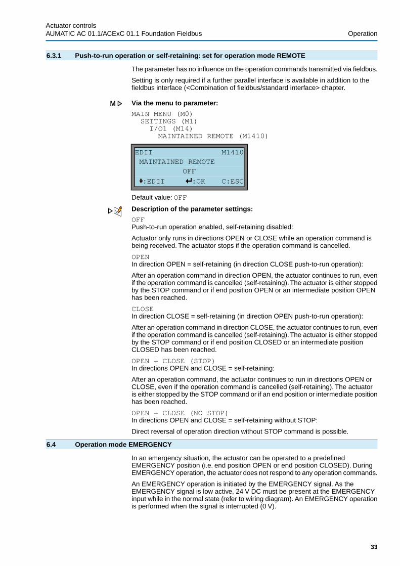
6.3.1 Push-to-run operation or self-retaining: set for operation mode REMOTE
The parameter has no influence on the operation commands transmitted via fieldbus.
Setting is only required if a further parallel interface is available in addition to thefieldbus interface (<Combination of fieldbus/standard interface> chapter.
Via the menu to parameter:
MAIN MENU (M0) SETTINGS (M1) I/O1 (M14) MAINTAINED REMOTE (M1410)
EDIT M1410 MAINTAINED REMOTE
OFF
:EDIT :OK C:ESC
Default value: OFF
Description of the parameter settings:
OFFPush-to-run operation enabled, self-retaining disabled:
Actuator only runs in directions OPEN or CLOSE while an operation command isbeing received. The actuator stops if the operation command is cancelled.
OPENIn direction OPEN = self-retaining (in direction CLOSE push-to-run operation):
After an operation command in direction OPEN, the actuator continues to run, evenif the operation command is cancelled (self-retaining).The actuator is either stoppedby the STOP command or if end position OPEN or an intermediate position OPENhas been reached.
CLOSEIn direction CLOSE = self-retaining (in direction OPEN push-to-run operation):
After an operation command in direction CLOSE, the actuator continues to run, evenif the operation command is cancelled (self-retaining).The actuator is either stoppedby the STOP command or if end position CLOSED or an intermediate positionCLOSED has been reached.
OPEN + CLOSE (STOP)In directions OPEN and CLOSE = self-retaining:
After an operation command, the actuator continues to run in directions OPEN orCLOSE, even if the operation command is cancelled (self-retaining). The actuatoris either stopped by the STOP command or if an end position or intermediate positionhas been reached.
OPEN + CLOSE (NO STOP)In directions OPEN and CLOSE = self-retaining without STOP:
Direct reversal of operation direction without STOP command is possible.
6.4 Operation mode EMERGENCY
In an emergency situation, the actuator can be operated to a predefinedEMERGENCY position (i.e. end position OPEN or end position CLOSED). DuringEMERGENCY operation, the actuator does not respond to any operation commands.
An EMERGENCY operation is initiated by the EMERGENCY signal. As theEMERGENCY signal is low active, 24 V DC must be present at the EMERGENCYinput while in the normal state (refer to wiring diagram). An EMERGENCY operationis performed when the signal is interrupted (0 V).
33
Actuator controlsAUMATIC AC 01.1/ACExC 01.1 Foundation Fieldbus Operation

After initiating an EMERGENCY operation (the EMERGENCY input is again suppliedwith 24 V DC), operation commands OPEN, STOP, CLOSE must be deleted andissued anew.
Analogue operation commands (e.g. 0/4 – 20 mA) or operation commands via fieldbusare immediately executed again.
Information Prerequisites for this function:● in addition to the fieldbus interface, the AUMATIC is equipped with a further
parallel interface. Refer to <Combination of fieldbus/standard interface> chapter.● the AUMATIC is equipped with additional control inputs. Refer to <Additional
bus inputs>.
6.4.1 Operation mode: activate for EMERGENCY operation
Via the menu to parameter:
MAIN MENU (M0) SETTINGS (M1) EMERGENCY BEHAVIOUR (M16) EMERG.SEL.SW.POS. (M1612)
EDIT M1612 EMERG.SEL.SW.POS
REMOTE ONLY
:EDIT :OK C:ESC
Default value: REMOTE ONLY
Description of the parameter settings:
REMOTE ONLYEmergency operation only possible in selector switch position REMOTE.
REMOTE AND LOCALEmergency operation possible in selector switch position REMOTE and LOCAL.
Information No emergency operation is performed when the selector switch is in position OFF.
6.4.2 EMERGENCY operation: enable/disable/signal behaviour definition
Via the menu to parameter:
MAIN MENU (M0) SETTINGS (M1) EMERGENCY BEHAVIOUR (M16) EMERGENCY BEHAVIOUR (M1610)
EDIT M1610 EMERGENCY BEHAVIOUR
OFF
:EDIT :OK C:ESC
Default value: OFF
Description of the parameter settings:
OFFEmergency operation is disabled.
GOOD SIGNAL FIRSTAn EMERGENCY operation is only triggered when the EMERGENCY signal at theEMERGENCY input drops from 24 V to 0 V, i.e. provided that a 24 V signal waspreviously connected to the EMERGENCY input.
ACTIVE IMMEDIATE
34
Actuator controlsOperation AUMATIC AC 01.1/ACExC 01.1 Foundation Fieldbus

An EMERGENCY operation is only initiated if 0 V are connected to the EMERGENCYsignal input. For "Active immediately", an EMERGENCY operation is initiatedimmediately after the actuator is switched on, when 0 V are connected to theEMERGENCY input.
Risk of immediate actuator operation when switching on!
Risk of personal injuries or damage to the valve
→ Ensure that the EMERGENCY signal is present when switching on.→ If the actuator starts unexpectedly: immediately turn selector switch to position
0 (OFF).
6.4.3 Actuator behaviour definition in case of an emergency operation
Via the menu to parameter:
MAIN MENU (M0) SETTINGS (M1) EMERGENCY BEHAVIOUR (M16) EMERGENCY POSITION (M1611)
EDIT M1611 EMERGENCY POSITION
FAIL AS IS
:EDIT :OK C:ESC
Default value: FAIL AS IS
Description of the parameter settings:
FAIL AS ISThe actuator stops in the current position.
FAIL CLOSEThe actuator runs to end position CLOSED.
FAIL OPENThe actuator runs to end position OPEN.
FAIL TO PRESETThe actuator runs to the predetermined position.
6.4.4 EMERGENCY position definition
If the EMERGENCY operation action FAIL TO PRESET (EMERGENCY POSITIONparameter) is set, the actuator runs to the EMERGENCY position stated here.
Via the menu to parameter:
MAIN MENU (M0) SETTINGS (M1) EMERGENCY BEHAVIOUR (M16) PRESET POSITION (M1614)
EDIT M1614 PRESET POSITION
0.0 %
:EDIT :OK C:ESC
Default value: 0.0 %
Setting range: from 0.0 % to 100.0 % (from OPEN to CLOSED)
35
Actuator controlsAUMATIC AC 01.1/ACExC 01.1 Foundation Fieldbus Operation

6.4.5 Motor protection and/or torque switching by-pass
During EMERGENCY operation, the motor protection and/or torque switching canbe by-passed.
This value is set in the factory and can only be changed by authorised AUMA staff.
Via the menu to parameter:
MAIN MENU (M0) SETTINGS (M1) EMERGENCY BEHAVIOUR (M16) EMERGENCY BY-PASS (M1603)
EDIT M1603 EMERGENCY BY-PASS
NONE
:EDIT :OK C:ESC
Default value: NONE
Description of the parameter settings:
NONENo by-pass of motor protection.
THERMOThe signals of the thermoswitches or the PTC thermistors of the motor winding areby-passed.
TORQUEThe signals of the torque switching in the actuator (TSC (DSR)/TSO (DOEL)) areby-passed
THERMAL AND TORQUEThe signals of the thermoswitches or PTC thermistors and the signals of the torqueswitching are by-passed.
Information It is not possible to by-pass the motor protection for actuators with explosion protec-tion.
6.5 Failure behaviour on loss of signal
Fault state behaviour on loss of bus communication
The fault state behaviour determines the actuator reaction to loss of buscommunication.
To activate the failure behaviour on loss of bus communication, the fault statebehaviour of the Foundation Fieldbus function block (AOFB or DOFB) has to beconfigured.The fault state behaviour is configured via Foundation Fieldbus by meansof a configuration software.
For further information, please refer to the Manual (Device integration fieldbus).
Failure behaviour in case of analogue signal loss (option)
Failure behaviour determines the actuator behaviour on loss of an analogue 4 – 20mA setpoint signal.
Conditions:
● In addition to the Foundation Fieldbus interface, the AUMATIC is equipped witha further parallel interface. Refer to <Combination of fieldbus/standard interface>chapter.
● The AUMATIC is equipped with additional control inputs. Refer to <Combinationof fieldbus/standard interface> chapter.
If the failure mode is enabled, the display indicates:
36
Actuator controlsOperation AUMATIC AC 01.1/ACExC 01.1 Foundation Fieldbus

FAILURE MODE S0
6.5.1 Failure behaviour enable/disable
Via the menu to parameter:
MAIN MENU (M0) SETTINGS (M1) FAILURE BEHAVIOUR (M15) FAILURE BEHAVIOUR (M1510)
EDIT M1510 FAILURE BEHAVIOUR
OFF
:EDIT :OK C:ESC
Default value: OFF
Description of the parameter settings:
OFFFailure behaviour is disabled.
GOOD SIGNAL FIRSTA failure operation is only initiated when no wire break is recognised after switchingon, but wire break is recognised later through loss of signal.
With this setting, it is ensured that the actuator does not perform a preset failureaction (failure position) when switched on without connected signal.
FAIL IMMEDIATEThe failure behaviour is initiated in case of signal loss.
Risk of immediate actuator operation when switching on!
Risk of personal injuries or damage to the valve
→ Set selector switch to position LOCAL or OFF when switching on.→ Only switch on actuator when mounted.→ Make sure that the signal set in FAILURE SOURCE parameter is available
when switching the actuator on.
6.5.2 Source for initiation (failure source): set for failure operation
Via the menu to parameter:
MAIN MENU (M0) SETTINGS (M1) FAILURE BEHAVIOUR (M15) FAILURE SOURCE (M1514)
EDIT M1514 FAILURE SOURCE
E1 OR E2 FEEDBACK
:EDIT :OK C:ESC
Default value: E1 OR E2 FEEDBACK
Description of the parameter settings:
SETPOINT E1
37
Actuator controlsAUMATIC AC 01.1/ACExC 01.1 Foundation Fieldbus Operation

In case of loss of setpoint E1, the failure behaviour is triggered..
The monitoring depends on the preset setpoint range, e.g.:
● E1 = 4 – 20 mA, E1 lower than 3.7 mA = loss of signal● E1 = 10 – 20 mA, E1 lower than 9.7 mA = loss of signalMonitoring of E1 = 0 – 20 mA is not possible
E1 OR E2 FEEDBACKIn case of loss of setpoint E1 or feedback E2, the failure behaviour is triggered.
The following is monitored:
● Potentiometer in the actuator: Cable break is detected● For actuators with electronic position transmitter RWG 4 – 20 mA: E2 lower
than 3.7 mA = loss of signal● For actuators with MWG: Communication faults and MWG internal faults are
recognisedE1, E2, E4 FEEDBACKIn case of loss of setpoint E1 or feedback E2 or process variable E4, the failurebehaviour is triggered.
6.5.3 Actuator reaction (failure position): setting on loss of signal
Via the menu to parameter:
MAIN MENU (M0) SETTINGS (M1) FAILURE BEHAVIOUR (M15) FAILURE POSITION (M1512)
EDIT M1512 FAILURE POSITION
OFF
:EDIT :OK C:ESC
Default value: FAIL AS IS
Description of the parameter settings:
FAIL AS ISThe actuator stops in the current position.
FAIL CLOSEThe actuator runs to end position CLOSED.
FAIL OPENThe actuator runs to end position OPEN.
FAIL TO PRESETThe actuator runs to the predetermined position.
Behaviour depending on the selector switch position:
If the actuator is in failure mode, the set failure position is approached via a failureoperation. If the actuator is then moved to another position (e.g. by manual operation),it will try to perform the set failure action while the selector switch is in positionREMOTE.
Information To prevent a new approach to the failure position during manual operation, the se-lector switch (local controls) must be switched to position LOCAL or OFF beforeoperating the handwheel.
6.5.4 Preset position: define
Via the menu to parameter:
MAIN MENU (M0) SETTINGS (M1)
38
Actuator controlsOperation AUMATIC AC 01.1/ACExC 01.1 Foundation Fieldbus

FAILURE BEHAVIOUR (M15) PRESET POSITION (M1513)
EDIT M1513 PRESET POSITION
0.0 %
:EDIT ↵:OK C:ESC
Default value: 0.0 %
Setting range: from0.0 % to 100,0 % (from OPEN to CLOSED)
6.5.5 Failure delay time setting
Via the menu to parameter:
MAIN MENU (M0) SETTINGS (M1) Failure behaviour (M15) DELAY TIME (M1511)
EDIT M1513 DELAY TIME
3.0 s
:EDIT ↵:OK C:ESC
Default value: 3.0 s
Setting range: from 0.0 to 1 200.0 seconds (20 minutes)
39
Actuator controlsAUMATIC AC 01.1/ACExC 01.1 Foundation Fieldbus Operation

7. Functions and settings
7.1 Type of seating: check/edit for end positions
Valve damage due to incorrect setting!
→ The type of seating must suit the valve.→ Only change the setting with the consent of the valve manufacturer.
Limit seating The limit switching is set in such a way that the actuator switches off at the desiredswitching points. The torque switching acts as overload protection for the valve.
Torque seating The torque switching is set to the desired tripping torque. After reaching the trippingtorque, the actuator is switching off.
The limit switching is used for signalling and must be set to trip shortly before reachingthe set tripping torque. If this is not the case, one of the following fault signals isdisplayed: TSO FAULTS or TSC FAULTS (menu S1).
Via the menu to parameter:
MAIN MENU (M0) SETTINGS (M1) SEATING MODE (M11) OPEN POSITION (M11_0) CLOSED POSITION (M11_1)
EDIT M1110OPEN POSITION
LIMIT
:EDIT :OK C:ESC
EDIT M1111CLOSED POSITION
LIMIT
:EDIT :OK C:ESC
Default value: LIMIT
7.2 Torque switching: check/set
This setting is only possible for the non-intrusive version
The torque switching acts as overload protection over full travel and is active evenif actuator is set to limit seating in end positions.
Information The torque switches may also trip during manual operation.
Valve damage due to excessive tripping torque limit setting!
→ The tripping torque must suit the valve.→ Only change the setting with the consent of the valve manufacturer.
Via the menu to parameter:
MAIN MENU (M0) SETTINGS (M1) TORQUE (M12) OPENING (M12_0) CLOSING (M12_1)
40
Actuator controlsFunctions and settings AUMATIC AC 01.1/ACExC 01.1 Foundation Fieldbus

EDIT M1210OPENING100%
:EDIT :OK C:ESC
EDIT M1211DREHMOMENT ZU
100%
:EDIT :OK C:ESC
Default value: according to order data
Setting range: according to torque setting range, refer to actuator name plate
Information The value can be displayed in percent, Newtonmeter (Nm), or in Lbs/ft. To displayin percent: 100 % equals the max. torque indicated on the name plate of the actuator.Example: SA 07.5 with 20 – 60 Nm: 100 % = 60 Nm (33 % = 20 Nm).
Information The following fault signals are issued if the torque setting performed has been reachedin mid-travel:
● Status indication S0: Operation mode OFF/LOCAL = FAULT IND.● Status indication S0/S6: Operation mode REMOTE = FAULT IND.● Status indication S1: TORQUE FAULT (OPEN) or TORQUE FAULT
(CLOSE) (torque fault)● The Foundation Fieldbus APVB transducer block signals a fault via XD_ERROR
(General Error, 17 (0x11)) and XD_ERROR_EXT (Torque fault OPEN,0x00000001 or Torque fault CLOSE, 0x00000002), thus generating an operationmode change of the DOFB or AOFB to the IMan status.
The fault has to be acknowledged before the operation can be resumed. Theacknowledgement is made:
1. either by an operation command in the opposite direction.- For TORQUE FAULT (CLOSE): Operation command in direction OPEN- For TORQUE FAULT (OPEN): Operation command in direction CLOSE
2. or, in case the torque applied is lower than the preset tripping torque:- via the push button Reset in selector switch position LOCAL.- or via the Foundation Fieldbus APPLICATION_RESET parameter of the
APVB transducer block (index 784).
7.3 Limit switching: set
This setting is only possible for the non-intrusive version.
Via the menu to parameter:
MAIN MENU (M0) SETTINGS (M1) SET LIMIT SWITCHES (M10) CLOSED POSITION (M100) OPEN POSITION (M101)
SET LIMIT SWITC M100
CLOSED POSITION63.3 %
:EDIT :OK C:ESC
41
Actuator controlsAUMATIC AC 01.1/ACExC 01.1 Foundation Fieldbus Functions and settings

SET LIMIT SWITC M101
OPEN POSITION63.3 %
:EDIT :OK C:ESC
Information For end position setting, turn selector switch to LOCAL position and move the actuatorinto the end position, either via manual or motor operation (using the push buttons).Then turn the selector switch back to OFF position and accept end position.
Valve damage due to direct approaching of mechanical end stop during motoroperation!
→ During motor operation, interrupt travel before reaching the mechanical valve/ge-arbox end stop (press push button STOP).
Information If an end position cannot be set: Check the type of control unit in actuator.
7.4 Intermediate positions
— Option —
Up to 8 intermediate positions can be defined for the AUMATIC.
Condition The actuator is either equipped with:
● an MWG (for Non-Intrusive version), or● a potentiometer (5 Ω) or● an RWGIn these versions, the positioning of the intermediate positions is made via softwareparameters.
Selection of the intermediate positions can be made either via push buttons fromLOCAL or via the fieldbus interface from REMOTE with the standard commandsOPEN and CLOSE. The actuator stops when reaching the intermediate position.The operation command has to be cleared by means of the STOP command andissued again to resume operation to the next intermediate position.
Information If the intermediate positions are to be approached directly (without stop), the multiportvalve function is available as an option. Refer to <Intermediate positions with multiportvalve function> chapter.
7.4.1 Display indication: enable view
The INTERMED. POSITION parameter must be set to VIEW ENABLED to carryout settings in the intermediate positions.
Via the menu to parameter:
MAIN MENU (M0) CONFIGURATION (M4) SPECIAL FUNCTIONS (M40) INTERMED. POSITION (M4015)
EDIT M4015INTERMED. POSITIONVIEW NOT ENABLED
:EDIT :OK C:ESC
Default value: VIEW NOT ENABLED
42
Actuator controlsFunctions and settings AUMATIC AC 01.1/ACExC 01.1 Foundation Fieldbus

Description of the parameter settings:
VIEW NOT ENABLEDThe parameters for the intermediate positions are not indicated in the display.
VIEW ENABLEDThe parameters for the intermediate positions are indicated in the display.
7.4.2 Intermediate positions: activate/deactivate
Each intermediate position (POS.1 to POS.8) may individually beactvated/deactivated.
Via the menu to parameter:
MAIN MENU (M0) SETTINGS (M1) INTERMED. POSITION (M1C) POS.1: AKTIVIERUNG (M1C12)
EDIT M1C12POS.1: SELECTOR SW.
OFF
:EDIT :OK C:ESC
Default value: OFF
Description of the parameter settings:
OFFIntermediate position switched off.
REMOTE ONLYIntermediate position only active in operation mode REMOTE.
LOCAL ONLYIntermediate position only active in operation mode LOCAL.
REMOTE AND LOCALIntermediate position active in operation modes REMOTE and LOCAL.
7.4.3 Intermediate position definition
Each intermediate position (POS.1 to POS.8) can be set to any value between 0% and 100 % of the travel.
Via the menu to parameter:
MAIN MENU (M0) SETTINGS (M1) INTERMED. POSITION (M1C) POS.1 (M1C10)
EDIT M1C10POS.10.0 %
:EDIT :OK C:ESC
Default value: 0.0 %
Setting range: 0.0 % to 100.0 % of the travel (from OPEN to CLOSED)
7.4.4 Operation behaviour = actuator behaviour definition
The reaction of the actuator upon reaching an intermediate position can beprogrammed via POS.1 BEHAVIOUR bis POS.8 BEHAVIOUR
43
Actuator controlsAUMATIC AC 01.1/ACExC 01.1 Foundation Fieldbus Functions and settings

Via the menu to parameter:
MAIN MENU (M0) SETTINGS (M1) INTERMED. POSITION (M1C) POS.1 BEHAVIOUR (M1C11)
EDIT M1C11POS.1 BEHAVIOUR
NO STOP
:EDIT :OK C:ESC
Default value: NO STOP
Description of the parameter settings:
NO STOPNo intermediate stop, actuator continues the operation.
STOP OPENING DIR.Actuator stops during operation in direction OPEN upon having reached theintermediate position. Actuator only runs after a new operation command is issued.
This function is not active in the operation mode SETPOINT MODE.
STOP CLOSING DIR.Der Antrieb bleibt bei Fahrt in Richtung ZU beim Erreichen der Zwischenstellungstehen. Actuator only runs after a new operation command is issued.
This function is not active in the operation mode SETPOINT MODE.
STOP BOTH DIR.Actuator stops after reaching the intermediate position. Actuator only runs after anew operation command is issued.
This function is not active in the operation mode SETPOINT MODE.
7.4.5 Signalling of intermediate positions: set
The reaching of an intermediate position can be signalled:
● via bus (see separate instructions)● via indication lights (LEDs) of the local controls or● via output contactsThe signal behaviour of the individual intermediate positions is set via the POS.1-4CONTROL parameters:
Via the menu to parameter:
MAIN MENU (M0) SETTINGS (M1) INTERMED. POSITION (M1C) POS.1: SIGNAL (M1C13)
EDIT M1C13POS.1: CONTROL
NOT USED
:EDIT :OK C:ESC
Default value: NOT USED
Description of the parameter settings:
NOT USEDNo signal.
C_ _ _ POS¯ ¯ ¯OSignal active from reaching of the intermediate position to end position OPEN.
44
Actuator controlsFunctions and settings AUMATIC AC 01.1/ACExC 01.1 Foundation Fieldbus

C¯ ¯ ¯POS_ _ _ OSignal active from reaching of the intermediate position to end position CLOSED..
C_ _ _ POS_ _ _ OImpulse signal issued when going through intermediate position
Figure 17: Signal behaviour of intermediate positions
1 Active signal2 Signal not activatedPOS Intermediate positionA NOT USEDB C_ _ _ POS¯ ¯ ¯OC C¯ ¯ ¯POS_ _ _ OD C_ _ _ POS_ _ _ O
Further feedback signals which can be used together with the multiport valve function(option):
Description of the parameter settings:
SETPOINT POSITIONAs each intermediate position is processed as a setpoint, the SETPOINT REACHEDsignal is issued after reaching any intermediate position.
ACTUATOR MOVINGIs signalled as long as the actuator is still running to the intermediate position andno intermediate position signal has been issued yet.
7.5 Intermediate positions with multiport valve function
— Option —
Tthe multiport valve function allows the selection of the eight intermediate positionseither directly from LOCAL (via push buttons) or from REMOTE (via special fieldbuscommands). Hereby the selected intermediate position is approached directly,without stopping in another intermediate position.
In this case, the actuator continues running until the selected intermediate positionhas been reached. Example: Operation from position 5 to 7 without stopping atposition 6. This function is available with operation commands from LOCAL via thepush buttons or from REMOTE via a fieldbus interface.
Limitation: When equipped with a parallel interface, the direct selection function is only availablein local operation, since the number of control cables is not sufficient for the selectionof a specific intermediate position.
7.5.1 Check: Multiport valve function available?
The multiport valve is available if the POS. DIRECTRUNNING (M400B)parameter is displayed in the SPECIAL FUNCTIONS (M40) menu.
45
Actuator controlsAUMATIC AC 01.1/ACExC 01.1 Foundation Fieldbus Functions and settings
Via the menu to parameter:
MAIN MENU (M0) CONFIGURATION (M4) SPECIAL FUNCTIONS (M40) POS DIRECTRUNNING (M400B)
VIEWPOS DIRECT RUNNINGFUNCTION ACTIVE
C:ESC
Default value: FUNCTION NOT ACTIVE
Description of the parameter settings:
FUNCTION NOT ACTIVEMultiport valve function off = selection of the respective subsequent intermediateposition via OPEN - CLOSE commands
FUNCTION ACTIVEMultiport valve function on = direct selection of intermediate positions possible fromboth REMOTE and LOCAL.
Information The function is either activated or deactivated via the EDIT menu. This value is setin the factory and can only be changed by the AUMA service.
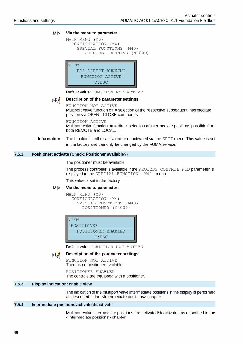
7.5.2 Positioner: activate (Check: Positioner available?)
The positioner must be available.
The process controller is available if the PROCESS CONTROL PID parameter isdisplayed in the SPECIAL FUNCTION (M40) menu.
This value is set in the factory.
Via the menu to parameter:
MAIN MENU (M0) CONFIGURATION (M4) SPECIAL FUNCTIONS (M40) POSITIONER (M4000)
VIEW POSITIONER
POSITIONER ENABLEDC:ESC
Default value: FUNCTION NOT ACTIVE
Description of the parameter settings:
FUNCTION NOT ACTIVEThere is no positioner available.
POSITIONER ENABLEDThe controls are equipped with a positioner.
7.5.3 Display indication: enable view
The indication of the multiport valve intermediate positions in the display is performedas described in the <Intermediate positions> chapter.
7.5.4 Intermediate positions activate/deactivate
Multiport valve intermediate positions are activated/deactivated as described in the<Intermediate positions> chapter.
46
Actuator controlsFunctions and settings AUMATIC AC 01.1/ACExC 01.1 Foundation Fieldbus

7.5.5 Intermediate position definition
Each of the 8 intermediate positions must be programmed. For direct selection ofthe intermediate positions from either LOCAL or REMOTE, it is sufficient to definethe position (POS.1-8 parameter) of each intermediate position.
Via the menu to parameter:
MAIN MENU (M0) SETTINGS (M1) INTERMED. POSITION (M1C) POS.1 (M1C10)
EDIT M1C10POS.10.0 %
:EDIT :OK C:ESC
Setting ranges: 0.0 % to 100.0 % of the travel (from OPEN to CLOSED)
Typically all 8 outputs of the valve are distributed evenly over 360°, therefore theselector switch CLOSE should be set to output 1 and the selector switch OPEN tooutput 8. Afterwards the positions of the intermediate positions can be set:
Intermediate position 1: POS. 1 = 0.0 % (output 1)
Intermediate position 2: POS. 2 = 14.3 % (output 2)
Intermediate position 3: POS. 3 = 28.6 % (output 3)
Intermediate position 4: POS. 4 = 42.9 % (output 4)
Intermediate position 5: POS. 5 = 57.1 % (output 5)
Intermediate position 6: POS. 6 = 71.4 % (output 6)
Intermediate position 7: POS. 7 = 85.7 % (output 7)
Intermediate position 8: POS. 8 = 100.0 % (output 8)
7.5.6 Operation behaviour = actuator behaviour definition
The operation behaviour setting of the multiport valve intermediate positions isperformed as described in the <Intermediate positions> chapter.
7.5.7 Intermediate positions: set the signalling
The signal behaviour setting of the multiport valve intermediate positions is performedas described in the <Intermediate positions> chapter.
The reaching of an intermediate position can be signalled:
● via bus (see separate instructions)● via indication lights (LEDs) of the local controls or● via output contactsIn addition to the "Intermediate position" signal, the following signals can be used incombination with the multiport valve function:
SETPOINT POSITIONAs each intermediate position is processed as a setpoint, theSETPOINT REACHEDis issued after reaching any intermediate position.
ACTUATOR MOVINGIs signalled as long as the actuator is still running to the intermediate position andno intermediate position signal has been issued yet.
7.5.8 Intermediate positions in LOCAL: direct approach without stopping
Via the menu to parameter:
MAIN MENU (M0)
47
Actuator controlsAUMATIC AC 01.1/ACExC 01.1 Foundation Fieldbus Functions and settings

RUNNING TO POS5 (M5) POS. NUMBER (M50)
Now enter desired intermediate position.
→ Set selector switch to position Local control (I).
Actuator runs to selected intermediate position
Indication an display during operation:
RUN TO INTERM.POS
P5 60 %
E2 67 %RUNNING CLOSE
P5 = Selected intermediate position
E2 = Position feedback
Indication in display after reaching intermediate position:
RUN TO INTERM.POS
P5 60 %
E2 60 %SETPOINT POSITION
To approach a new intermediate position:
1. Set selector switch to position OFF (0)
2. Enter desired intermediate position.
3. Set selector switch to position Local control (I).
Actuator runs to desired intermediate position.
7.6 Positioner (SETPOINT MODE operation mode)
The positioner records setpoint position E1 and actual position value E2 and comparesboth. Depending on the detected deviation, the actuator motor then runs in directionsOPEN or CLOSE.
The positioner is only active in operation mode REMOTE (selector switch = positionRemote control).
If the positioner is active, the display shows:
REMOTE SETPOINT S0
E1 60 %
E2 60 %SETPOINT POSITION
48
Actuator controlsFunctions and settings AUMATIC AC 01.1/ACExC 01.1 Foundation Fieldbus

Information If the display shows REMOTE MODE, the actuator is set to open-close duty and nomodulation is performed. In this case, you have to change-over to modulating dutyfirst, refer to <Change-over between open-close duty and modulating duty> chapter.If the display shows S6 instead of S0 and E7 instead of E1, then the positioner isactivated. Refer to <Process controller> chapter.
7.6.1 Positioner: activate (Check: Positioner available?)
The positioner must be available.
The process controller is available if the PROCESS CONTROL PID parameter isdisplayed in the SPECIAL FUNCTION (M40) menu.
This value is set in the factory.
Via the menu to parameter:
MAIN MENU (M0) CONFIGURATION (M4) SPECIAL FUNCTIONS (M40) POSITIONER (M4000)
VIEW POSITIONER
POSITIONER ENABLEDC:ESC
Default value: FUNCTION NOT ACTIVE
Description of the parameter settings:
FUNCTION NOT ACTIVEThere is no positioner available.
POSITIONER ENABLEDThe controls are equipped with a positioner.
7.6.2 Adaptive behaviour: activate/deactivate
As standard, the adaptive positioning is activated, i.e. overrun and max. error variableare automatically defined by the positioner.
If the setting is to be made manually, the ADAPTIVE BEHAVIOUR parameter mustbe in position OFF.
Via the menu to parameter:
MAIN MENU (M0) CONFIGURATION (M4) SPECIAL FUNCTIONS (M40) ADAPTIVE BEHAVIOUR (M4011)
EDIT M4011ADAPTIVE BEHAVIOUR
ON
:EDIT :OK C:ESC
Default value: ON
Description of the parameter settings:
OFFAdaptive behaviour deactivated.
ONAdaptive behaviour activated.
49
Actuator controlsAUMATIC AC 01.1/ACExC 01.1 Foundation Fieldbus Functions and settings

Figure 21: Positioner control behaviour
E1 SetpointE2 Actual valueP1 Switch-on pointP2 Switch-off point in direction OPENP3 Setpoint reachedT1 Outer dead bandT2 Max. error variableT3 Inner dead bandT4 Overrun
7.6.3 Overrun (inner dead band): manual setting
The inner dead band determines the switch-off point of the actuator and thereforeinfluences the overrun.
The inner dead band may be set individually for the directions OPEN and CLOSE.
Manual setting is only possible, if the adaptive behaviour (ADAPTIVE BEHAVIOURparameter) is deactivated.
Via the menu to parameter:
MAIN MENU (M0) SETTINGS (M1) POSITIONER (M119) OPENING DEADBAND (M1913) CLOSING DEADBAND (M1914)
Example of dead band OPEN
EDIT M1913OPENING DEADBAND
0.5 %
:EDIT :OK C:ESC
Default values: 0.5 % (for dead band OPEN and CLOSE)
Setting ranges: 0.0 % to 9.9 % (for dead band OPEN and CLOSE)
50
Actuator controlsFunctions and settings AUMATIC AC 01.1/ACExC 01.1 Foundation Fieldbus

Information ● Inner dead bands may not be set wider than outer dead bands.● Inner dead bands may not be set too narrow as this may cause unnecessary
switching procedures (premature wear) or oscillation of the actuator.
.
7.6.4 Max. error variable (outer dead band): manual setting
The outer dead band determines the switching-on point of the actuator.
The motor switches on when the actual value (input signal E2) or a setpoint changeexceeds the max. error variable determined by the max. error variable.
Manual setting is only possible, if the adaptive behaviour (ADAPTIVEBEHAVIOURparameter) is switched off.
Via the menu to parameter:
MAIN MENU (M0) SETTINGS (M1) POSITIONER (M119) OUTER DEADBAND (M1915)
EDIT M1915OUTER DEADBAND
1.0 %
:EDIT :OK C:ESC
Default value: 1.0 %
Setting range: 0.1 % to 9.9 %
7.6.5 Dead time: set
The dead time prevents the operation to a new setpoint position within apredetermined time.
Via the menu to parameter:
MAIN MENU (M0) SETTINGS (M1) POSITIONER (M119) DEAD TIME (M1910)
EDIT M1915DEAD TIME (T-OFF)
0.5 s
:EDIT :OK C:ESC
Default value: 0.5 s
Setting range: 0.0 % to 60.0 % seconds
Information It must be ensured via the controls that the max. permissible number of starts of theactuator is not exceeded. This can be achieved by setting the dead time to a suffi-ciently high value.
7.6.6 Closing fully/opening fully (end position tolerance for setpoint E1)
If the end positions cannot be reached due to inaccurate analogue setpoint signals(0/4 mA or 20 mA), a tolerance for the setpoint within the end position range can beset. If the tolerance is exceeded or not reached, the actuator continues the operationuntil the full end position has been reached. This ensures that the actuator opensand closes fully.
51
Actuator controlsAUMATIC AC 01.1/ACExC 01.1 Foundation Fieldbus Functions and settings

Information The tolerance ranges are not effective if the operation commands are transferred tothe actuator as fieldbus telegrams. In this case the actuator runs completely CLOSEas soon as it receives the setpoint 0 % and completely OPEN as soon as it receivesthe setpoint 100.0 %.
Via the menu to parameter:
MAIN MENU (M0) SETTINGS (M1) POSITIONER (M119) FULL OPEN ADJUST (M1911) FULL CLOSE ADJUST (M1912)
Example of Full OPEN Adjust:
EDIT M1911FULL OPEN ADJUST
100 %
:EDIT :OK C:ESC
Default value: FULL OPEN ADJUST = 100 %
Default value: FULL CLOSE ADJUST = 0 %
Setting ranges: FULL OPEN ADJUST = 95 % to 100 % of the travel
Setting ranges: FULL CLOSE ADJUST = 0 % to 50 % of the travel
7.6.7 Change-over between OPEN - CLOSE control and setpoint control
Selection between OPEN - CLOSE control and setpoint control is defined by theappropriate function blocks:
● OPEN - CLOSE control: Use Discrete Output Function Block (DOFB).● Setpoint control: Use Analog Output Function Block (AOFB).
Information These two function blocks may not be used simultaneously.
The following versions also allow a change-over between OPEN-CLOSE control andSETPOINT control via the MODE input (refer to wiring diagram):
● Iin addition to the fieldbus interface, the AUMATIC is equipped with a furtherparallel interface (refer to <Combination of fieldbus/standard interface> chapter).
● The AUMATIC is equipped with additional control inputs (refer <Additional inputsfor bus> chapter )
MODE input: +24 V DC = REMOTE MODE = OPEN -CLOSE control, i.e. control isexecuted via digital commands OPEN - STOP - CLOSE
MODE input: 0 V (or input open) = REMOTE SETPOINT = setpoint control, i.e. thecontrol is executed via an analogue signal (e.g. 0/4 – 20 mA).
7.6.8 Source of setpoint E1: view
This value is set in the factory and can only be changed by the AUMA service.
Via the menu to parameter:
MAIN MENU (M0) CONFIGURATION (M4) SETUP (M41) SETPOINT E1 (M4100)
VIEW SETPOINT E1
FOUNDATION FIELDBUSC:ESC
52
Actuator controlsFunctions and settings AUMATIC AC 01.1/ACExC 01.1 Foundation Fieldbus

Default value: FOUNDATION FIELDBUS
Description of the parameter settings:
NONEThere is no setpoint source available.
LOGIC ANALOG IN1For AUMA service only (the setpoint E1 is transmitted from external via the analogueinput 1 directly to the logic board.
I/O1 ANALOG IN1The setpoint E1 is transmitted via the I/O board interface, analogue input 1.
I/O1 ANALOG IN2The setpoint E1 is transmitted via the I/O board interface, analogue input 2.
FOUNDATION FIELDBUSThe setpoint E1 is transmitted via the Foundation Fieldbus interface board.
FF1 ANALOG IN1The setpoint E1 is transmitted via the Foundation Fieldbus interface board, analogueinput 1.
FF1 ANALOG IN2The setpoint E1 is transmitted via the Foundation Fieldbus interface board, analogueinput 2.
7.6.9 Input range of setpoint E1: view/edit
The parameters of this setting depend on the pre-set setpoint source, SETPOINTE1 (M4100) parameter.
Initial and end value via the Foundation Fieldbus interface
In Foundation Fieldbus standard version, the setpoint E1 is transmitted via the AOfunction block.
Initial and end value via I/O interface
For the following versions, setpoint E1 can be transmitted via an analogue inputinstead of the fieldbus (channel 1 or channel 2).
1. In addition to the fieldbus interface, the AUMATIC is equipped with a furtherparallel interface (refer to <Combination of fieldbus/standard interface> chapter).
2. The AUMATIC is equipped with additional control inputs (refer <Additional inputsfor bus> chapter).
The input range amounts to 0/4 – 20 mA. It is possible to modify the input range viathe display for both versions:
Version 1, setpoint source of parallel interface, analogue input 1:
Via the menu to parameter:
MAIN MENU (M0) CONFIGURATION (M4) SETUP (M41) I/O1 ANLOG IN1 START (M410H) I/O1 ANLOG IN1 END (M410I)
Example of show initial value:
VIEWI/O ANLOG IN1 START
0.0 mAC:ESC
Default value: I/O ANLOG IN1 START = 0 mA
Default value: I/O ANLOG IN1 END = 20 mA
Setting ranges: I/O ANLOG IN1 START = 0 to 20 mA
53
Actuator controlsAUMATIC AC 01.1/ACExC 01.1 Foundation Fieldbus Functions and settings

Version 2, setpoint source of Foundation Fieldbus interface, analogue input1:
Via the menu to parameter:
MAIN MENU (M0) SETTINGS (M1) FF-INTERFACE 1 (M1M) FF ANLOG IN1 START (M4M00) FF ANLOG IN1 END (M4M01)
Example of show initial value:
VIEWFF ANLOG IN1 START
0.0 mAC:ESC
Default value: FF ANLOG IN1 START = 0 mA
Default value: FF ANLOG IN1 END = 20 mA
Setting ranges:FF ANLOG IN1 START = 0 to 20 mA (initial value and end value)
Information If the measuring values are 0.3 mA below the initial value a wire break is indicatedas a warning.
7.7 Stepping mode
— Option —
With stepping mode, the operating time can be increased for the entire or any portionof the valve travel.
54
Actuator controlsFunctions and settings AUMATIC AC 01.1/ACExC 01.1 Foundation Fieldbus

Figure 22: Stepping mode
[1] Stepping range OPEN[2] Stepping range CLOSEP1 Start of stepping modeP2 End of stepping modet1 Operating time for normal operationt2 Operating time for stepping modet3 Running timet4 Off time
Information Stepping mode is only possible if a position transmitter (potentiometer, RWG, orMWG) is installed in the actuator.
7.7.1 Display indication: enable view
To perform settings for stepping mode via the display, the Stepping modeparameter must be in position View enabled.
Via the menu to parameter:
MAIN MENU (M0) CONFIGURATION (M4) SPECIAL FUNCTIONS (M40) TAKTBETRIEB (M4014)
EDIT M4014STEPPING MODE
VIEW NOT ENABLED
:EDIT :OK C:ESC
Default value: VIEW NOT ENABLED
Description of the parameter settings:
VIEW NOT ENABLEDThe parameters for the stepping mode are not indicated in the display.
VIEW ENABLEDThe parameters for the stepping mode are indicated in the display.
55
Actuator controlsAUMATIC AC 01.1/ACExC 01.1 Foundation Fieldbus Functions and settings

7.7.2 Stepping mode: enable/disable
Stepping mode can be individually activated for the directions OPEN and CLOSE.
Via the menu to parameter:
MAIN MENU (M0) SETTINGS (M1) STEPPING MODE (M17) DIRECTION OPEN (M170) DIRECTION CLOSE (M1715)
EDIT M1710DIRECTION OPEN
OFF
:EDIT :OK C:ESC
Default value: OFF (both directions)
Description of the parameter settings:
OFFStepping mode is switched off.
REMOTE ONLYStepping mode only possible in operation mode REMOTE.
LOCAL ONLYStepping mode only possible in operation mode LOCAL.
REMOTE AND LOCALStepping mode possible in operation modes REMOTE and LOCAL.
7.7.3 Stepping range setting (start and end of stepping mode).
For both directions the stepping range (start and end of stepping mode) can be setseparately.
Via the menu to parameter:
Example of Start Step OPEN display:MAIN MENU (M0) SETTINGS (M1) STEPPING MODE (M17) START STEP OPEN (M1713) STOP STEP OPEN (M1714) START STEP CLOSE (M1718) STOP STEP CLOSE (M1719)
Example of Initial value OPEN display:
EDIT M1713START STEP OPEN
0.0 %
:EDIT :OK C:ESC
Default values:
START STEP OPEN = 0.0 %
STOP STEP OPEN = 100.0 %
START STEP CLOSE = 100.0 %
STOP STEP CLOSE = 0.0 %
Setting ranges:
START STEP OPEN = 0.0 % to 99.9 %
56
Actuator controlsFunctions and settings AUMATIC AC 01.1/ACExC 01.1 Foundation Fieldbus

STOP STEP OPEN = 0.1 % to 100.0 %
START STEP CLOSE = 0.1 % to 100.0 %
STOP STEP CLOSE = 0.0 % to 99.9 %
7.7.4 ON and OFF times: set
On or off times can be set individually for directions OPEN and CLOSE.
Via the menu to parameter:
Example of Start Step OPEN display:MAIN MENU (M0) SETTINGS (M1) STEPPING MODE (M17) ON TIME OPEN (M1711) ON TIME OPEN (M1712) OFF TIME CLOSE (M1716) OFF TIME CLOSE (M1717)
Example of On time OPEN display
EDIT M17111ON TIME OPEN
10.0 s
:EDIT :OK C:ESC
Default values:
ON TIME OPEN = 10.0 s
OFF TIME OPEN = 50.0 s
ON TIME CLOSE = 10.0 s
OFF TIME CLOSE = 50.0 s
Setting ranges:
ON TIME OPEN = 1.0 to 300.0 seconds
OFF TIME OPEN = 1.0 to 300.0 seconds
OFF TIME CLOSE = 1.0 to 300.0 seconds
ON TIME CLOSE = 1.0 to 300.0 seconds
7.8 Release function of local controls
— Option —
The selector switch functions on the local controls (LOCAL, OFF, and REMOTE)may be either enabled or disabled.
7.8.1 Selector switch functions: enable/disable
This value is set in the factory and can only be changed by the AUMA service.
Via the menu to parameter:
MAIN MENU (M0) CONFIGURATION (M4) SETUP (M41) ENABLE LOCAL MODE (M410W)
VIEW ENABLE LOCAL MODE
NOT ACTIVEC:ESC
57
Actuator controlsAUMATIC AC 01.1/ACExC 01.1 Foundation Fieldbus Functions and settings

Description of the parameter settings:
Default value: NOT ACTIVE
NOT ACTIVEAll selector switch functions are enabled.
FOUNDATION FIELDBUSThis setting is only permissible if there is an selector switch on the local controls.
The selector switch function is enabled via the ENABLE_LOCAL_CONTROLSFoundation Fieldbus parameter of the APVB transducer block (index 785). Theselector switch functions LOCAL, OFF, and REMOTE may be enabled or disabledeither separately or combined. Refer to Manual (Device integration Fieldbus)Foundation Fieldbus.
The following fault signals are emitted if one out of the three selector switch positionsis not enabled while the Foundation Fieldbus communication is active.
● Status indication S0: RESTRICTED.● Status indication S0: RESTRICTED.The Foundation Fieldbus APVB transducer
block signals a fault via XD_ERROR (General Error, 17 (0x11)) and XD_ER-ROR_EXT (Not ready Indication, 0x00000010), thus generating an operationmode change of the DOFB or AOFB to the IMan status.
If the communication via Foundation Fieldbus is not available, all three selectorswitch positions are enabled.
I/OThe push buttons are used to disable or enable the actuator operation via the digitalRELEASE input (see wiring diagram). This setting is only permissible if there is anselector switch on the local controls (SELECTOR SWITCH = AVAILABLEparameter).
● Disabling operation via push buttons:No signal at the RELEASE input (the status indication S0 in the display shows“RESTRICTED").
● Enabling operation via push buttons:Apply + 24 V DC signal at the RELEASE input.
7.9 EMERGENCY stop function
— Option —
The AUMATIC can also be equipped with an EMERGENCY stop button. Whenengaged, this EMERGENCY stop interrupts the 24 V AC control voltage of thecontactors.
Information The EMERGENCY stop push button is not available for the ACExC, but only for theweatherproof versions of the AUMATIC.
7.9.1 Description of the functions
As soon as this EMERGENCY STOP button is operated, several steps are performedwithin the AUMATIC:
58
Actuator controlsFunctions and settings AUMATIC AC 01.1/ACExC 01.1 Foundation Fieldbus

● The 24 V AC control voltage of the AUMATIC contactors is interrupted.● Switching off the operation command and cancelling a possibly set self-retaining.● Option: The operation status of the EMERGENCY STOP button is indicated by
activating an output contact.● Option: The operation status of the EMERGENCY STOP button is indicated by
an indication light (LED) lighting up on the local controls.● Message in the display of the diagnosis indication S3: NOT READY IND.
with the entry EMCY STOP ACTIVE.● Message in the display of the status indication S0: OPERATION STATUS
EMCY STOP.● The Foundation Fieldbus APVB transducer block signals a fault via XD_ERROR
(General Error, 17 (0x11)) and XD_ERROR_EXT (Not ready Indication,0x00000010), thus generating an operation mode change of the DOFB or AOFBto the IMan status.
After having unlocked the EMERGENCY stop button, a possibly active operationcommand will NOT immediately be re-activated, but only after respectiveacknowledgement by the operator. This resets the EMERGENCY STOP status.
The acknowledgement is made:
● via the push button Reset in selector switch position LOCAL.● via the push button Reset in selector switch position LOCAL or via Foundation
Fieldbus APPLICATION_RESET parameter of the APVB Transducer Block(Index 784).
After this, operation commands as well as emergency and failure operations willimmediately be performed.
7.9.2 Feedback signals on the display
Status indication S0 shows:
EMERGENCY STOP S0
Status indication S3 shows:
NOT READY IND. S3EMCY STOP ACTIVE
Description of the indications:
EMCY STOP/EMCY STOP ACTIVEThe EMERGENCY stop button has been operated and has put the AUMATIC intothe EMERGENCY stop status. This status can only be cancelled by unlocking theEMERGENCY stop button and issuing a subsequent RESET command.
7.9.3 Feedback signals setting via output contacts
Via the menu to parameter:
MAIN MENU (M0) SETTINGS (M1) I/O 1 (M14) OUTPUT CONTACT 1 - 5
Example of output contact 1
59
Actuator controlsAUMATIC AC 01.1/ACExC 01.1 Foundation Fieldbus Functions and settings

EDIT M1412OUTPUT CONTACT 1EMCY STOP BUTTON
:EDIT :OK C:ESC
Setting values:
EMCY STOP BUTTONThe selected output contact is activated, after the EMERGENCY stop button wasoperated.
This signal can be cancelled by unlocking the EMERGENCY stop button.
7.9.4 Feedback signal setting via LEDs
Via the menu to parameter:
MAIN MENU (M0) SETTINGS (M1) LOCAL CONTROLS (M13) LED 1 - 4
Example of LED 2:
EDIT M1313LED 2
EMCY STOP BUTTON
:EDIT :OK C:ESC
Setting values:
EMCY STOP BUTTONThe selected LED is illuminated after the EMERGENCY STOP button was operated.
This signal can be cancelled by unlocking the EMERGENCY STOP button.
7.10 Foundation Fieldbus interface
All Foundation Fieldbus interface settings (including the device address assignment)are made via the Foundation Fieldbus. For this reason, the local operation (via thedisplay) of the AUMATIC does not supply any Foundation Fieldbus relevantparameter.
In the menu only those parameters used for setting both analogue inputs are available.These parameters only affect the local behaviour of the analogue inputs (e.g. whenused as local analogue setpoint input). Irrespective of these parameter settings, thesignal behaviour via Foundation Fieldbus is exclusively configured using the AIFB1or AIFB2 function blocks.
Via the menu to the fieldbus parameters:
MAIN MENU (M0) SETTINGS (M1) FF-INTERFACE 1 (M1M)
7.11 Additional bus inputs
— Option —
Parallel control via external inputs is possible for an AUMATIC with fieldbus interface.
Four binary 24 V DC inputs and two analogue 0/4 – 20 mA inputs are available.
Irrespective of the signal assignment of these inputs, the fieldbus communicationwith the DCS will remain intact.
7.11.1 Signal assignment for operation commands
Via the menu to parameter:
MAIN MENU (M0)
60
Actuator controlsFunctions and settings AUMATIC AC 01.1/ACExC 01.1 Foundation Fieldbus
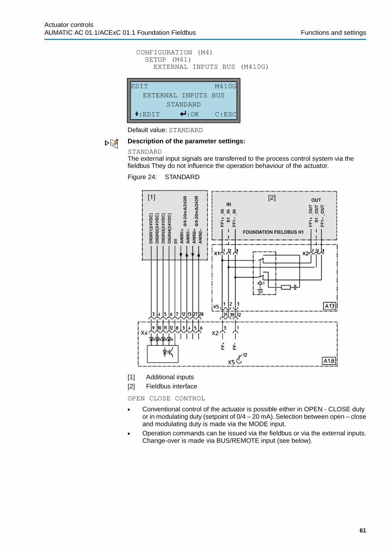
CONFIGURATION (M4) SETUP (M41) EXTERNAL INPUTS BUS (M410G)
EDIT M410GEXTERNAL INPUTS BUS
STANDARD
:EDIT :OK C:ESC
Default value: STANDARD
Description of the parameter settings:
STANDARDThe external input signals are transferred to the process control system via thefieldbus They do not influence the operation behaviour of the actuator.
Figure 24: STANDARD
[1] Additional inputs[2] Fieldbus interface
OPEN CLOSE CONTROL
● Conventional control of the actuator is possible either in OPEN - CLOSE dutyor in modulating duty (setpoint of 0/4 – 20 mA). Selection between open – closeand modulating duty is made via the MODE input.
● Operation commands can be issued via the fieldbus or via the external inputs.Change-over is made via BUS/REMOTE input (see below).
61
Actuator controlsAUMATIC AC 01.1/ACExC 01.1 Foundation Fieldbus Functions and settings

Figure 25: OPEN CLOSE CONTROL
[1] Additional inputs[2] Fieldbus interface
OPEN CLOSE ESD
● Actuator control is possible in open-close duty (OPEN – CLOSE - EMERGENCY)only. Modulating duty is not possible.
● Operation commands can be issued via the fieldbus or via the external inputs.Change-over is made via BUS/REMOTE input (see below).
● Operation commands are made in push-to-run operation only.● If a voltage of 0 V is present at EMERGENCY input, the actuator performs the
programmed EMERGENCY operation irrespective of the BUS/REMOTE input.
Figure 26: OPEN CLOSE ESD
[1] Additional inputs[2] Fieldbus interface
OPEN CLOSE STOP
● Actuator control is possible in open-close duty (OPEN – CLOSE - STOP) only.Modulating duty is not possible.
● Operation commands can be issued via the fieldbus or via the external inputs.Change-over is made via BUS/REMOTE input (see below).
● Operation commands are made in self-retaining only.
62
Actuator controlsFunctions and settings AUMATIC AC 01.1/ACExC 01.1 Foundation Fieldbus

Figure 27: OPEN CLOSE STOP
[1] Additional inputs[2] Fieldbus interface
Information In the event of loss of bus communication, the additional inputs do not automaticallytake over!
Information Please refer to the Manual (Fieldbus device integration) for details on fieldbus feed-back signals.
Switching between operation commands via fieldbus and external inputs
● Apply 0 V DC (input open) at BUS/REMOTE input: Controls react to fieldbussignals only.
● Apply + 24 V DC at BUS/REMOTE input. The controls react to additional inputsignals only: MODE, CLOSE,OPEN, STOP,EMERGENCY, ANIN1 (the availableexternal inputs depend on the parameter setting).
Information For the version <Equal control via fieldbus and parallel inputs>, change-over is onlypossible it the SELECT BUS <-> IO (M401F) parameter ist set to INPUTBUS/EXTERN.
7.12 Combination of fieldbus/standard interface
— Option —
The actuator controls is equipped with both a fieldbus interface and a parallelinterface, if the I/O stack 2parameter status shows I/O.
Via the menu to parameter:
MAIN MENU (M0) CONFIGURATION (M4) SETUP (M41) I/O STACK 2 (M410Q)
VIEW I/O STACK 2 I/O
C:ESC
63
Actuator controlsAUMATIC AC 01.1/ACExC 01.1 Foundation Fieldbus Functions and settings

Figure 28: Wiring diagram extract showing both fieldbus interface and parallel in-terface
[1] Fieldbus interface[2] Parallel interface
Switch between operation commands via fieldbus and parallel inputs
● Apply 0 V DC (input open) at BUS/REMOTE input: Controls react to fieldbussignals only.
● Apply +24 V DC (optional 115 V AC) at BUS/REMOTE input.The controls reactto additional input signals only. MODE; CLOSE, OPEN, STOP, EMERGENCY,ANIN1+, ANIN1–.
Information If a voltage of 0 V is present at EMERGENCY input, the actuator performs the pro-grammed EMERGENCY operation (refer to page ), irrespective of the BUS/REMOTEinput.
Information In the event of loss of bus communication, the additional inputs do not automaticallytake over!
Information Please refer to the Manual (Fieldbus device integration) for details on fieldbus feed-back signals.
Information For the version <Equal control via fieldbus and parallel inputs>, change-over is onlypossible it the SELECT BUS <-> IO (M401F) parameter ist set to INPUTBUS/EXTERN.
7.13 Equal control via fieldbus and parallel inputs
— Option —
Condition <Additional inputs> or additional <Parallel interface>.
Use the SELECT BUS <-> I/O parameter for setting equal control of operationcommands via fieldbus and operation commands via parallel inputs.
This value is set in the factory and can only be changed by the AUMA service.
Via the menu to parameter:
MAIN MENU (M0) CONFIGURATION (M4) SPECIAL FUNCTIONS (M40) SELECT BUS <-> IO (M401F)
64
Actuator controlsFunctions and settings AUMATIC AC 01.1/ACExC 01.1 Foundation Fieldbus

EDIT M401F SELECT BUS <-> IO
AUTO
:EDIT ↵:OK C:ESC
Default value: INPUT BUS/EXTERN
Description of the parameter settings:
INPUT BUS/EXTERNThe controls either respond to operation commands from fieldbus or to operationcommands present at the parallel inputs.The change-over of the control is executedvia BUS/REMOTE input (0 V DC = fieldbus; 24 V DC = parallel inputs)
AUTOThe operation command source, which has sent the last operation command, isactive. Whether the operation command was received via parallel input or fieldbusdoes not make any difference. An operation command is a command that initiatesa movement, i.e. Run OPEN, Run CLOSE.
On loss of the bus communication, the fieldbus interface is selected as operationcommand source if there is no operation command received via parallel input. Aparameter based failure operation may then be performed.
7.14 Partial Valve Stroke Test (PVST)
— Option —
Requirements ● <Additional inputs> or additional <Parallel interface>.● Position transmitter in actuator● Function <Positioner> activated.
Features and behaviour
Normal operation The Partial Valve Stroke Test (PVST) is used to check the function of both actuatorand controls. During this test, the function of the valve is tested by means of partialopening or closing within a defined period of time without interrupting the process.After successful test, controls operate the actuator to its initial position.
The test can only be performed during OPEN - CLOSE control. For setpoint control(modulating duty), a test cannot be performed.
The test cannot be started via fieldbus. The operation command to be initiated forthe Partial Valve Stroke Test is triggered via a binary signal at digital input XK3.
● Input XK3: +24 V DC (low-high edge) = test is started● Input XK3: 0 V (or input open) = test not possible
in case of a failure Basically the following applies:
If one of the faults below is present before the test actually starts, a PVST cannotbe executed.
If one of the following faults occurs during the test, the PVST will be aborted.
Faults● Status indication S0 FAULT IND., triggered by the following faults:
- Thermal fault (motor protection)- Torque fault- Internal error
● Status indication S0 NOT READY, triggered by an EMERGENCY operation.● Status indication S0 FAILURE MODE, triggered e.g. due to loss of bus com-
munication.
Information The successful completion of the PVST has to be completed externally by evaluationof the feedback signals (e.g. by the user or the DCS.)
65
Actuator controlsAUMATIC AC 01.1/ACExC 01.1 Foundation Fieldbus Functions and settings

7.14.1 PVST: activate
This value is set in the factory and can only be changed by the AUMA service.
Via the menu to parameter:
MAIN MENU (M0) CONFIGURATION (M4) SPECIAL FUNCTIONS (M40) PVST FUNCTION (M401E)
EDIT M401E PVST FUNCTION
FUNCTION NOT ACTIVE
:EDIT :OK C:ESC
Default value: FUNCTION NOT ACTIVE
Description of the parameter settings:
FUNCTION NOT ACTIVEPVST function switched off.
FUNCTION ACTIVEPVST function switched on.
7.14.2 Travel difference:set
The parameter determines the partial valve stroke to be executed during the PartialValve Stroke Test.
Via the menu to parameter:
MAIN MENU (M0) CONFIGURATION (M4) SETUP (M41) PVST STROKE (M411r)
EDIT M411r PVST STROKE
10.0%
:EDIT :OK C:ESC
66
Actuator controlsFunctions and settings AUMATIC AC 01.1/ACExC 01.1 Foundation Fieldbus

8. Monitoring and safety functions
8.1 Torque monitoring
The torque monitoring serves as overload protection over the whole travel.
Depending on the version, the required tripping torques are either set via the torqueswitching in the actuator or via the OPENING and CLOSING parameters(Non-Intrusive version).
If the set torques are reached in mid-travel, the actuator will be stopped and thefollowing fault signals will be sent:
● Status indication S0: Operation mode OFF/LOCAL = FAULT IND.● Status indication S0/S6: Operation mode REMOTE = FAULT IND.● Status indication S1: TORQUE FAULT (OPEN) or TORQUE FAULT
(CLOSE) (torque fault)● The Foundation Fieldbus APVB transducer block signals a fault via XD_ERROR
(General Error, 17 (0x11)) and XD_ERROR_EXT (Torque fault OPEN,0x00000001 or Torque fault CLOSE, 0x00000002), thus generating an operationmode change of the DOFB or AOFB to the IMan status.
The fault has to be acknowledged before the operation can be resumed. Theacknowledgement is made:
1. either by an operation command in the opposite direction.- For TORQUE FAULT (CLOSE): Operation command in direction OPEN- For TORQUE FAULT (OPEN): Operation command in direction CLOSE
2. or, in case the torque applied is lower than the preset tripping torque:- via the push button Reset in selector switch position LOCAL.- or via the Foundation Fieldbus APPLICATION_RESET parameter of the
APVB transducer block (index 784).
Set torque by-pass
Valve damage due to excessive torque!
→ Only apply torque by-pass with the consent of the valve manufacturer.
Via the menu to parameter:
MAIN MENU (M0) SETTINGS (M1) TORQUE (M12) BY-PASS DURATION (M1212)
EDIT M1212BY-PASS DURATION
0.0 s
:EDIT :OK C:ESC
Default value: 0.0 s
Setting range: 0.0 to 50.0 seconds
8.2 Motor protection (thermal monitoring)
In order to protect against overheating and impermissibly high surface temperaturesat the actuator, PTC thermistors or thermoswitches are embedded in the motorwinding. The thermoswitch is tripped as soon as the max. permissible windingtemperature has been reached.
The actuator is switched off and the following signals are given:
● LED 3 (thermal fault) on the local controls is illuminated.● Status indication S0: Operation mode OFF/LOCAL = FLT + NR
67
Actuator controlsAUMATIC AC 01.1/ACExC 01.1 Foundation Fieldbus Monitoring and safety functions

● Status indication S0/S6: Operation mode REMOTE = FAULT IND.● The Foundation Fieldbus APVB transducer block signals a fault via XD_ERROR
(General Error, 17 (0x11) and XD_ERROR_EXT (Thermal fault, 0x00000200),thus generating an operation mode change of the DOFB or AOFB to the IManstatus.
The motor has to cool down before the operation can be resumed.
Depending on the parameter setting, the fault signal is either automatically reset orthe fault signal has to be acknowledged.
The acknowledgement is made:
● via push button Reset in selector switch position LOCAL.● via push button Reset in selector switch position LOCAL or via Foundation
Fieldbus APPLICATION_RESET parameter of the APVB Transducer Block(Index 784).
View motor protection
This value is set in the factory.
Via the menu to parameter:
MAIN MENU (M0) CONFIGURATION (M4) SETUP (M41) MOTOR PROTECTION (M4108)
VIEW MOTOR PROTECTION
THERMAL CONT. (AUTO)
C:ESC
Default values:
Non Ex actuators = THERMAL CONT. (AUTO)
Ex actuators: = THERMISTOR (RESET)
Description of the parameter settings:
THERMAL CONT. (AUTO)Automatic reset after the motor has cooled down.
Not possible for explosion-proof version ACExC 01.1
THERMAL CONT. (RESET)Manual reset.
The acknowledgement is made:
● via push button Reset in selector switch position LOCAL.● or via the Foundation Fieldbus APPLICATION_RESET parameter of the APVB
transducer block (index 784).If required the thermal overload relay has to be reset manually. To this end, removethe cover on the back of the AUMATIC and operate the Reset button on the thermaloverload relay.
THERMISTOR (RESET)Manual reset.
The acknowledgement is made:
● via push button Reset in selector switch position LOCAL.● or via the Foundation Fieldbus APPLICATION_RESET parameter of the APVB
transducer block (index 784).THERMISTOR (AUTO)
68
Actuator controlsMonitoring and safety functions AUMATIC AC 01.1/ACExC 01.1 Foundation Fieldbus

Automatic reset after the motor has cooled down. Not possible for explosion-proofversion ACExC 01.1.
8.3 Monitoring of the max. number of starts per hour and max. running time per hour
The AUMATIC monitors any exceeding of
● the maximum number of starts (motor starts) per hour● the maximum running time (on-time) per hour.If any of these values has been exceeded, the actuator will however not be stopped,but the following warning signals are sent:
● Status indication S0: Operation mode OFF/LOCAL = WRN + NR● Status indication S0/S6: Operation mode REMOTE = WARNING IND.● Status indicationS2:ED WARNINGThe warning signals will automatically be cleared if the number of starts per secondand the set max. running time per hour are no longer reached.
An exceeding is also logged in the operating data counters WRN.STARTS/RUN1and WRN.STARTS/RUN2 .
WRN.STARTS/RUN1 contains the total of all on time warnings.
WRN.STARTS/RUN2 contains the max. time duration of a starts/running timewarning.
Example:
Due to excess of defined starts/h or defined running time/h, the AC issues in total 3on time warnings: two for 20 min, once for 15 min, once for 22 min. Afterwards theoperating data counters contain the following values:
WRN.STARTS/RUN1 = 57 min. total of all time sections (20+15+22 min)
WRN.STARTS/RUN2 = 22 min. = longest time section
Switch on/off the monitoring of the max. number of starts and the max. runningtime
To be able to view settings or to perform modifications, the MONITORING parametermust be set to FUNCTION ACTIVE.
Information This parameter is used to activate/deactivate the running time monitoring (MAX.RUNTIME parameter).
Via the menu to parameter:
MAIN MENU (M0) CONFIGURATION (M4) SPECIAL FUNCTIONS (MM40) MONITOR TRIGGERS (M4016)
EDIT M4016MONITOR TRIGGERSFUNCTION ACTIVE
:EDIT :OK C:ESC
Default value: FUNCTION ACTIVE
Description of the parameter settings:
FUNCTION NOT ACTIVEMAX STARTS/HOUR and MAX DUTY CYCLE parameters are not displayed.
FUNCTION ACTIVEMAX STARTS/HOUR and MAX DUTY CYCLE parameters are displayed.
69
Actuator controlsAUMATIC AC 01.1/ACExC 01.1 Foundation Fieldbus Monitoring and safety functions

Set the max. permissible number of starts
Via the menu to parameter:
MAIN MENU (M0) SETTINGS (M1) MONITOR TRIGGERS (M18) MAX. STARTS/HOUR (M1810)
EDIT M1810MAX. STARTS/HOUR
1200
:EDIT :OK C:ESC
Default value: 1200
Setting range: 0 to 1,800 starts (motor starts)
Set the max. permissible running time
Via the menu to parameter:
MAIN MENU (M0) SETTINGS (M1) MONITOR TRIGGERS (M18) MAX. DUTY CYCLE (M1811)
EDIT M1811MAX. DUTY CYCLE
15 MIN
:EDIT :OK C:ESC
Default value: 15 MIN
Setting range: 0 to 1,800 starts (motor starts)
Description of the parameter settings:
15 MINThe max. permissible running time (on-time) per hour amounts to 15 min.
24 MINThe max. permissible running time (on-time) per hour amounts to 24 min.
30 MINThe max. permissible running time (on-time) per hour amounts to 30 min.
8.4 Operating time monitoring
This function allows the monitoring of the operating time of the actuator. If the actuatorneeds longer than the set time (MAX. RUN TIME parameter) to move from endposition OPEN to end position CLOSED, the following warning signals are given (theactuator is not stopped):
● Status indication S0: Operation mode OFF/LOCAL = WRN + NR● Status indication S0/S6: Operation mode REMOTE = WARNING IND.● Status indication S2:: WARNING OPER. TIMEThe warning signals are automatically cleared when a new operation command isexecuted.
When the actuator moves from an intermediate position to an end position, the setmonitoring time for the whole stroke is assigned in relation to the remainingstroke/travel.
70
Actuator controlsMonitoring and safety functions AUMATIC AC 01.1/ACExC 01.1 Foundation Fieldbus

Switch operating time monitoring on/off
Information This parameter is also used to activate/deactivate the monitoring of the max. numberof starts per hour and the max. running time per hour.
Via the menu to parameter:
MAIN MENU (M0) CONFIGURATION (M4) SPECIAL FUNCTIONS MONITOR TRIGGERS (M4016)
EDIT M4016MONITOR TRIGGERSFUNCTION ACTIVE
:EDIT :OK C:ESC
Default value: FUNCTION ACTIVE
Description of the parameter settings:
FUNCTION NOT ACTIVEThe operating time monitoring is deactivated.
FUNCTION ACTIVEThe operating time monitoring is activated.
Set the max. permissible operating time
Via the menu to parameter:
MAIN MENU (M0) SETTINGS (M1) MONITOR TRIGGERS (M18) MAX. RUN TIME (M1812)
EDIT M1812MAX. RUN TIME
900 s
:EDIT :OK C:ESC
Default value: 900 s
Setting range: 4 to 36,000 seconds (4 seconds to 10 hours)
8.5 Reaction monitoring
The AUMATIC controls monitor the actuator reaction via the control unit of theactuator.
If no reaction is recorded at the output drive of the actuator within a set time(REACTION TIME parameter), the actuator is switched off and the following faultsignals are given:
● Status indication S0: Operation mode OFF/LOCAL = FLT + NR● Status indication S0/S6: Operation mode REMOTE = FAULT IND.● Status indication S1: INTERNAL ERROR● Diagnostic indication D2: NO REACTION● The Foundation Fieldbus APVB transducer block signals a fault via XD_ERROR
(Electronics Failure, 0x14) and XD_ERROR_EXT (Internal electronics error,0x00040000), thus generating an operation mode change of the DOFB or AOFBto the IMan status.
The fault has to be acknowledged. The acknowledgement is made:
● via the push button Reset in selector switch position LOCAL.
71
Actuator controlsAUMATIC AC 01.1/ACExC 01.1 Foundation Fieldbus Monitoring and safety functions

● or via the Foundation Fieldbus APPLICATION_RESET parameter of the APVBtransducer block (index 784).
In case of operation from an intermediate position, reaction monitoring will only beperformed if the actuator is equipped with position feedback function.
Switch reaction monitoring on/off
This value is set in the factory and may not be changed.
Via the menu to parameter:
MAIN MENU (M0) CONFIGURATION (M4) SPECIAL FUNCTIONS (M40) REACTION MONITORING (M4018)
EDIT M4018 REACTION MONITORING FUNCTION NOT ACTIVE
:EDIT :OK C:ESC
Default value: FUNCTION NOT ACTIVE
Description of the parameter settings:
FUNCTION NOT ACTIVEThe reaction monitoring is deactivated.
FUNCTION ACTIVEThe reaction monitoring is activated.
Set reaction time
Via the menu to parameter:
MAIN MENU (M0) SETTINGS (M1) REACTION MONITORING (M1H) REACTION TIME (M1H10)
EDIT M1812MAX. RUN TIME
900 s
:EDIT :OK C:ESC
Default value: 7 s
Setting range: 1.0 to 15.0 seconds
8.6 Phase failure monitoring
Requirements The phase failure monitoring is only valid for connections to 3-phase AC powersupplies. For versions with 1-phase AC or DC, phase sequence detection is notpossible.
Characteristics The AUMATIC monitors phase L2. If phase L2 is missing for a certain time interval,the AUMATIC still can send and receive signals and generates a fault indication.Since the AUMATIC is supplied via phases L1 and L3, the two phases cannot bemonitored. In case L1 or L3 fails, the AUMATIC is inoperable and the actuator stops.
72
Actuator controlsMonitoring and safety functions AUMATIC AC 01.1/ACExC 01.1 Foundation Fieldbus

Information In case of phase L2 loss during motor operation, this does not necessarily lead toan immediate standstill of the actuator.The reason is that the rotating motor generatesthe missing phase itself. This leads, however, to a reduction of the motor outputtorque. If the applied torque is sufficient for valve operation, the missing phase L2is only detected when switching off (e.g. in an end position) and the fault signalPHASE FAILURE is generated as a consequence.
The Foundation Fieldbus APVB transducer block signals a fault via XD_ERROR(General Error, 17 (0x11)) and XD_ERROR_EXT (Loss of phase, 0x00000100), thusgenerating an operation mode change of the DOFB or AOFB to the IMan status.
Enable/disable phase failure monitoring
Via the menu to parameter:
MAIN MENU (M0) SETTINGS (M1) PHASE MONITORING (M10)
EDIT M4018 PHASE MONITORING
10.0 s
:EDIT :OK C:ESC
Default value: 10.0 s
Setting range: 0.0 to 30.0 seconds
Information Faults in supply voltage (e.g. voltage drops) do not generate a fault signal during theperiod adjustable for this parameter.
73
Actuator controlsAUMATIC AC 01.1/ACExC 01.1 Foundation Fieldbus Monitoring and safety functions

9. Corrective action
9.1 Fault indications and warning indications
Faults interrupt or prevent the electrical actuator operation.
Warnings have no influence on the electrical actuator operation. They only servefor information purposes.
Fault and warning indications are shown in the display.
9.1.1 Status indication S0 - faults and warnings
Line 4 of status indication S0 displays faults and warnings.
LOCAL MODE S0OPEN
E2 100 %FAULT IND.
Table 4: Description of the fault indications
RemedyDescriptionSignal
For further information, press and go tostatus indication S1.
A fault has occurred.FAULT IND.
For further information, press and go tostatus indication S2.
A warning has occurred.WARNING IND.
For further information, press and go tostatus indication S1 (faults) or S2 (warnings).
Faults as well as warnings have occurred.FAULT + WARNING
For further information, press and go tostatus indication S3 (cause for fault indicati-ons).
The actuator cannot be operated from REMO-TE. The actuator can only be operated viathe local controls.
NOT READY IND.
For further information, press and go tostatus indication S1 or S3.
Faults and the NOT READY IND. signalhave occurred.
FLT + NR
For further information, press and go tostatus indication S2 or S3.
Warnings and the NOT READY IND. si-gnal have occurred.
WRN + NR
For further information, press and go tostatus indications S1 to S3.
Faults, warnings, and the NOT READYIND. signal have occurred.
FLT + WRN + NR
9.1.2 Status indication S1 - faults
Faults are indicated within the status indication S1:
FAULT IND. S1NO FAULT
74
Actuator controlsCorrective action AUMATIC AC 01.1/ACExC 01.1 Foundation Fieldbus

Table 5: Description of the fault indications
RemedyDescriptionSignalNo fault has occurred.NO FAULT
For further information:1. Go to group D0: Press C and hold it
down until diagnostic indication D0 isdisplayed.
2. Go to diagnostic indication D2: Press twice.
Internal fault has occurred.INTERNAL FAULT
Operation command in direction OPEN.Torque fault in direction CLOSE.TORQUE FAULT (CLOSE)Set selector switch to position Local control(LOCAL) and reset fault indication via pushbutton Reset.Or:Perform reset command via fieldbus.
Operation command in direction CLOSE.Torque fault in direction OPEN.TORQUE FAULT (OPEN)Set selector switch to position Local control(LOCAL) and reset fault indication via pushbutton Reset.Or:Perform reset command via fieldbus.
Test/connect phases.One phase is missing.LOSS OF PHASECool down, wait.Motor protection tripped.THERMAL FAULTIf the fault indication display persists aftercooling down:Set selector switch to position Local control(LOCAL) or reset fault indication via pushbutton Reset.Or:Perform reset command via fieldbus.
Check fuse F4.
For further information:1. Go to group D0: Press C and hold it
down until diagnostic indication D0 isdisplayed.
2. Go to diagnostic indication D4: Press 4 x.
The controls configuration is incorrect.CONFIGURATION FAULT
9.1.3 Status indication S2 - warnings
Faults are indicated within the status indication S2:
WARNING IND. S2NO WARNINGS
Table 6: Description of the warnings
RemedyDescriptionSignalNo warnings have occurred.NO WARNINGS
Set the operating time (MONITOR TRIG-GERS parameter) in accordance with theactual operating time.
Preset running time for a travel between endposition OPEN and end position CLOSEDhas been exceeded.
WARNING OPER. TIME
Check tripping behaviour of end positionswitches.
Verify actuator mechanics.
75
Actuator controlsAUMATIC AC 01.1/ACExC 01.1 Foundation Fieldbus Corrective action

RemedyDescriptionSignalCheck modulating behaviour.Preset values for max. starts/h or max. run-
ning time/h have been exceeded.WARNING STARTS/RUN
Increase dead time.
Reduce number of setpoint changes.
Operate actuator into both end positions(OPEN and CLOSED).
Position transmitter (potentiometer or RWG)is not standardised.
INTERNAL FEEDBACK
For further information:1. Go to group D0: Press C and hold it
down until diagnostic indication D0 isdisplayed.
2. Go to diagnostic indication D3: Press 3 times.
Internal warnings have occurred.INTERNAL WARNING
Check position transmitter signal.1. Go to group D0: Press C and hold it
down until diagnostic indication D0 isdisplayed.
2. Go to diagnostic indication D7, D8 orD9: Press either 7, 8 or 9 times.
Signal loss of position transmitterFEEDBACK E2 LOSS
Check position transmitter wiring.
Check POSITION E2 parameter. Thesetting must correspond to the wiring dia-gram.
Check wiring.Signal loss of setpointSETPOINT E1 LOSSCheck wiring.Signal loss of torque sourceTORQUE E6 LOSSCheck wiring.Signal loss of the analogue input 1 of the
parallel interface (only for fieldbus/standardinterface combinations)
I/O ANLOG IN1 LOSS
Check wiring.Signal loss of the analogue input 2 of theparallel interface (only for fieldbus/standardinterface combinations)
I/O ANLOG IN2 LOSS
Check wiring.Signal loss of actual process value E4 (onlyif PID controller is available and active)
P-FEEDBACK E4 LOSS
Check wiring.Signal loss of FO cable (for bus with FO looptopology only)
FIBER OPTIC LOSS
Check wiring.Signal loss of analogue input 1ANALOG IN1 BUS1 LOSSCheck wiring.Signal loss of analogue input 2ANALOG IN2 BUS1 LOSS
9.1.4 Status indication S3 - causes for not ready remote
The causes for the NOT READY IND. fault signals (from status indication S0) aredisplayed within status indication S3.
NOT READY IND. S3READY
76
Actuator controlsCorrective action AUMATIC AC 01.1/ACExC 01.1 Foundation Fieldbus

Table 7: Description of the fault indications
DescriptionSignalActuator can be operated from REMOTE.READYActuator cannot be operated from REMOTE as the selector switch is in position LOCALor OFF.
NOT REMOTE
Indicates that inadmissible operation commands have been received via FoundationFieldbus.
WRONG COMMAND
The EMERGENCY operation mode is active.EMERGENCY MODEFor combination fieldbus/standard interface function:Operation via parallel interface.
EXTERNAL CONTROLS
The EMERGENCY STOP button has been operated.EMCY STOP ACTIVEActuator locked (only set for special applications e.g. for by-pass function).ACTUATOR LOCKED
9.2 Diagnostic
9.2.1 Operating data logging
Operating data provides details e.g. about the running time, the number of starts,number of torque faults etc.
The analysis of this data provides valuable information regarding the optimization ofboth actuator and valve.When using this information purposefully, actuator and valvewill be carefully operated, e.g. through appropriate parameter setting. In case offaults, the logging of operating data allows for quick fault diagnostic.
9.2.1.1 Display indication: enable view
The operational data configuration must be set to VIEW ENABLED:
Via the menu to parameter:
MAIN MENU (M0) CONFIGURATION (M4) SPECIAL FUNCTIONS (M40) OPERATIONAL DATA (M4012)
EDIT M4012OPERATIONAL DATA
VIEW ENABLED
:EDIT :OK C:ESC
Default value: VIEW ENABLED
Description of the parameter settings:
VIEW NOT ENABLEDThe operational data is not indicated in the display.
VIEW ENABLEDThe operational data is indicated in the display.
9.2.1.2 Operating data: view
Via the menu to parameter:
MAIN MENU (M0)OPERATIONAL DATA (M2)
OPERATIONAL DATA M200
TOTAL MOTOR RUNTIME MOTOR RUN TIME TOTAL STARTS
77
Actuator controlsAUMATIC AC 01.1/ACExC 01.1 Foundation Fieldbus Corrective action

Various data is monitored by the AUMATIC and saved to a non-volatile memory(EEPROM). Two counters are provided, one of them is erasable. The recorded datacan be read and deleted via the display. The access right for deletion is passwordprotected.
Description of the indications:
The following applies:
TOTAL = Motor running time in the complete lifetime
without TOTAL = counter can be reset to 0.
MOTOR RUN TIMEMotor running time
STARTSNumber of starts (motor starts)
TSC STOPSNumber of torque switch stops in direction CLOSE
LSC STOPSNumber of limit switch stops in direction CLOSE
TSO STOPSNumber of torque switch trippings in direction OPEN
LSO STOPSNumber of limit switch trippings in direction OPEN
TORQUE FAULT (CLOSE)Number of torque faults in direction CLOSE
TORQUE FAULT (OPEN)Number of torque faults in direction OPEN
THERMAL FAULTNumber of thermal faults (motor protection)
WRN.STARTS/RUN1Total of all time sections during which a start/run warning was signalled.
WRN.STARTS/RUN2Max.period during which an ED warning was signalled.
NO. POWER ONNumber of all system starts.
9.2.2 Diagnostic indications (D) via the display
The information contained in the diagnostic indications is only provided for the AUMAservice and for enquiries in the factory.
Change from status indications (group S) to diagnostic indications (group D):
→ Press C push button and hold it down until the group DO appears (menu M ishereby skipped).
Return to status indications:
→ Press push-button C briefly once.
Wiring of the end position inputs (D0)
ENDPOS. INPUTS D0 PULL DOWN INPUTS
Description of the parameter settings:
PULL DOWN INPUTS
78
Actuator controlsCorrective action AUMATIC AC 01.1/ACExC 01.1 Foundation Fieldbus

Pull Down resistors are used for the inputs of the end position signals (limit andtorque switches) on the logic board.
PULL UP INPUTSPull Up resistors are used for the inputs of the end position signals (limit and torqueswitches) on the logic.
Actuator signals (D1)
ACTUATOR SIGNALS D1 NO SIGNALS
Description of the displays:
NO SIGNALSNo actuator signals set.
TSCTorque signal CLOSED in actuator tripped (not stored)
TSO (DOEL)Torque signal OPEN in actuator tripped (not stored)
LSC (WSR)Limit switching CLOSED in actuator tripped.
LSO (WOEL)Limit switching OPEN in actuator tripped.
THERMAL FAULTMotor protection tripped. Remedy:
● Wait for cool-down; the signal is then either cancelled automatically or if not,bring selector switch to position Local and operate push button Reset.
● Check fuse F4.
Internal faults (D2)
INTERNAL FAULTS D2 NO INTERNAL FAULT
Description of the displays:
NO INTERNAL FAULTNo internal fault has occurred.
THERMISTORA fault in the TMS tripping device was detected during start-up. Remedy: Checkwiring diagram and MOTOR PROTECTION (M4108). Check TMS tripping device.
SELECTOR SWITCHThe selector switch recognition is defective (no Hall sensor is tripped or more thanone Hall sensor is tripped). Remedy: Check local control board, check mechanicalattachment of the local controls in the housing.
OUTPUT TRANSISTORThe output of the operation commands to the relay board is defective, remedy: Checklogic board and relay board.
I/O1 CANNo communication to parallel interface available. Remedy: Setting of I/O STACK1 (M4106) must be in accordance with the wiring diagram, check wiring, checkparallel interface.
79
Actuator controlsAUMATIC AC 01.1/ACExC 01.1 Foundation Fieldbus Corrective action

PHASE DETECTIONThe phase sequence detection on the power supply is defective. Remedy: Checkphase sequence detection, check wiring.
24V DC FAULTThe internal 24 V supply of the AUMATIC is not within the supply voltage limits.Remedy: Check supply voltage, check power supply unit, check wiring of theAUMATIC voltage supply.
LOGIC CANThe logic cannot establish any communication.
NO REACTIONFault signal of the reaction monitoring
MWG CANNo communication to MWG available. Remedy: The I/O STACK 1 (M4106)setting must be in accordance with the wiring diagram; check wiring, check MWG.
MWG DEFECTIVEThe internal diagnostics of the MWG have detected a fault. Remedy:Replace/reconfigure MWG.
LOCAL CONTROL FAULTHardware fault of the local controls.
Internal warnings (D3)
INTERNAL WARNING D3 NO INTERNAL WARNING
Description of the warnings:
NO INTERNAL WARNINGNo internal warnings have occurred
NO FACTORY PARAMSNo valid factory settings available.
Configuration faults (D4)
CONFIGURATION ERROR D4 NO FAULT
Description of the displays:
NO FAULTAUMATIC has been correctly configured.
ENDPOS. INPUTSThe LIMIT/TORQUE-SWITCH parameter setting does not correspond to theENDPOS. INPUTS parameter configuration (can only be modified by AUMAservice).
NO SWITCHING OFFThe LIMIT/TORQUE-SWITCH parameter setting does not correspond to theCONTROL UNIT parameter configuration (can only be modified by AUMA service).
E1-IN NOT EXISTINGThe SETPOINT E1 parameter setting does not correspond to the I/O STACK1 (M4106) parameter configuration (can only be modified by AUMA service).
80
Actuator controlsCorrective action AUMATIC AC 01.1/ACExC 01.1 Foundation Fieldbus

Hardware version of the logic (D5)
LOGIC HRDWR. VER. D5
Description of the displays:
Indicates hardware version of the logic.
Software version of the logic (D6)
LOG SFTWR. VER. D6
Description of the displays:
Indicates software version of the logic.
Potentiometer values (D7)
POT. VALUE D7
Description of the displays:
Voltage values are displayed here if a potentiometer is installed:
● Line 2: Value in end position CLOSED● Line 3: Current value● Line 4: Value in end position OPEN
RWG value (D8)
RWG VALUE D8
Description of the displays:
Current values are displayed here if an RWG is installed:
● Line 2: Value in end position CLOSED● Line 3: Current value● Line 4: Value in end position OPEN
81
Actuator controlsAUMATIC AC 01.1/ACExC 01.1 Foundation Fieldbus Corrective action

MWG value (D9)
MWG VALUE D9
Description of the displays:
Raw values are displayed if an MWG is installed.
● Line 2: Value in end position CLOSED● Line 3: Current value● Line 4: Value in end position OPEN
MWG hardware version (DA)
MWG HRDW.VER. DA
Description of the displays:
The hardware version of the MWG is displayed if an MWG is installed.
MWG software version (DB)
MWG SFTWR.VER. DB
Description of the displays:
The software version of the MWG is displayed if an MWG is installed.
Positioner (DF)
POSITIONER ENABLED DF
Description of the displays:
Indicates determined values of the adaptive positioner.
● Line 2:Iinner dead band CLOSE● Line 3: Outer dead band● Line 4: Outer dead band CLOSE
82
Actuator controlsCorrective action AUMATIC AC 01.1/ACExC 01.1 Foundation Fieldbus

E1 value (DJ)
E1 VALUE DJ
Description of the displays:
Shows setpoint E1 in mA (only for standard I/O interface)
Internal faults 2 (DQ)
INTERNAL FAULT 2 DQ
Description of the displays:
RAM FAILURERAM of the logic defective. Remedy: Replace logic.
EEPROM FAILUREEEPROM of the logic defective. Remedy: Check logic, if necessary exchangeEEPROM.
FF CANNo communication to the Foundation Fieldbus interface available. Remedy: I/OSTACK1 (M4106) parameter must agree with the wiring diagram. Check wiring.Check I/O interface.
MWG status (Dd)
MWG STATUS Dd MWG OK
Description of the displays:
MWG OKMWG is working, no faults.
HALLSENSOR ERRORRemedy: Exchange MWG.
E2PROM ERRORRemedy: Exchange MWG.
NOT CALIBRATEDRemedy: Re-calibrate MWG (can only be performed in the factory).
NO POSITION REFEREN.Remedy: Re-calibrate MWG (can only be performed in the factory).
TORQUE SYSTEM FAULTRemedy: Exchange MWG.
NO ENDPOSITIONSRemedy: Re-set limit end positions (can only be performed in the factory).
NO TORQUE LIMITSRemedy: Re-set torque pivot points (can only be performed in the factory).
83
Actuator controlsAUMATIC AC 01.1/ACExC 01.1 Foundation Fieldbus Corrective action

FF HRDWR.VER. (De)
FF HRDWR.VER. Df
Description of the displays:
Indicates hardware version of the Foundation Fieldbus interface.
FF software version (Df)
FF SFTWR. VER. Df
Description of the displays:
Indicates software version of the Foundation Fieldbus interface.
FF device ID (Dg)
FF-DEVICE_ID Dg 0A01FF01F8-AUMA-AC01 -0304MA56018
Description of the displays:
The device ID is a worldwide unambiguous device identification. It serves the purposeof recognising a Foundation Fieldbus device by means of the fieldbus and, therefore,cannot be modified. The device ID comprises 32 characters and consists of themanufacturer ID (0x0A01FF), the device type (0x01F8), the text -AUMA-AC01-, aswell as the AUMATIC works number.
FF PD Tag (Dh)
FF-PD TAG Dh AUMATIC————-AC01 -0304MA56018
Description of the displays:
The PD Tag (Physical Device Tag) is the physical device name.The PD tag comprises32 characters and consists of the text AUMATIC - - - - - - - -AC01- and the worksnumber as default, when leaving the factory. The PD tag serves the purpose ofdevice identification within a plant and, therefore, the user may adapt the identificationvia Foundation Fieldbus as required.
84
Actuator controlsCorrective action AUMATIC AC 01.1/ACExC 01.1 Foundation Fieldbus

FF node address (Di)
FF-NODEADRESS Di FF NODEADRESS: 18/0x12
Station mode: BASIC MACROCYCLE 32000
Description of the indications:
NODEADRESSThe current device address as decimal and hexadecimal value.
Station mode: BASIC, when configuring the AUMATIC as Basic Device.
: LM, when configuring the AUMATIC as Link Master Device.
: LAS, if the AUMATIC has been configured as Link Master device and is workingas LAS (Link Active Scheduler).
MACROCYCLEThe preset macro cycle of the Foundation Fieldbus (unit 1/32 ms).
FF bus status (Dj)
FF BUS STATUS Dj DATA EX BUS ACTIVE
Description of the indications:
DATA EXIndicates active actuator controls via the Foundation Fieldbus interface; for this, theAPVB transducer block must be activated in AUTO and the DOFB or AOFB withinthe AUMATIC must be included in the FF scheduling. Thus, Data Ex signals anoperable local Foundation Fieldbus application within the AUMATIC.
BUS ACTIVEIndicates, that besides the AUMATIC, further Foundation Fieldbus devices areconnected to the same bus. This indicates correct wiring.
To ensure perfect function in combination with other devices, both DATA EX andBUS ACTIVE must be set.
FF schedule list Dk
FF-SCHEDULELIST Dk AO DO PID DI AI 1 1 1 123 1234 Y N Y NYN YNYN
Description of the displays:
The FF schedule list comprises the AUMATIC function blocks which can be calledup within the AUMATIC due to a function block application configured by the userand loaded into the AUMATIC.
The transducer blocks pertaining to the function blocks are not shown, as they aredirectly called up by the used function blocks; the same is valid for the resource blocknot being shown, as it will be automatically called up within the AUMATIC. Thecharacter below the function block number indicates, whether the respective function
85
Actuator controlsAUMATIC AC 01.1/ACExC 01.1 Foundation Fieldbus Corrective action

block is being called up within the AUMATIC or included in the FF Scheduling Y ornot N.
FF mode block Dl
FF-MODE_BLK Dl A O P R A 1 A 3 D 2 @ A C A A A A A A A C A C A A A A A O O
Description of the indications:
This display shows the target and actual operation modes of all function blocks calledup within the AUMATIC.The pertaining transducer block is shown with each functionblock (exceptions: resource block and PID function block).
Only those function blocks are shown being called up in the AUMATIC.
Figure 29: Function blocks and transducer blocks
[1] Target operation mode[2] Actual operation mode[3] Function block or transducer block
The following identifications are used for the target and actual operation modes ofthe function blocks:
Remote OutputROutRRemote CascadeRCaseRCascadeCasCAutomaticAutoAManualManMLocal OverrideLOLInitialisation ManualIManIOut of ServiceOOSOAutomatic and CascadeAutor+Cas@
This way, the states of all function blocks can be shown on one display page.
FF APVB XD Error (Dm)
FF-AVP_XDERROR Dm XD_ERR = 0X00 XDERREXT=0X0000000
Description of the displays:
Actuator problems or fault signals are signalled back to the function blocks via thetransducer blocks.The faults occurred are shown in the transducer blocks by means
86
Actuator controlsCorrective action AUMATIC AC 01.1/ACExC 01.1 Foundation Fieldbus

of the variables XD-ERROR and XD-ERROR_EXTENDED. The most importantactuator fault signals are combined via the APVB and transferred to the DOFB orAOFB, which will in turn take on a safe operation status. The contents of these twovariables are shown on the FF-APFB_XDERROR diagnostic page. For furtherreferences regarding the interpretation of the error codes shown, please refer to the“Manual (Device integration Fieldbus) AUMATIC AC 01.1/ACExC 01.1 FoundationFieldbus". Any existing error is simultaneously shown via the hitherto existing statusand diagnostic displays of the AUMATIC.
FF Live List (Dn)
FF-LIVE-LIST Dn 18, 21, 28
Description of the displays:
This diagnostic displays lists the first 15 device addresses comprised within theFoundation Fieldbus system. The comma after the last displayed device addressindicates that further participants are available.
It is only possible to dress the live list, if the AUMATIC is operated as Link MasterDevice (LM); otherwise the following is displayed:BASIC MODE, NO LIVE_LIST.
Bluetooth hardware version (D14)
BT-OSS-HW-VERSI D14
Description of the displays:
Indicates hardware version of the Bluetooth local controls.
Bluetooth software version (D15)
BT-OSS-SW-VERSI D15
Description of the displays:
Indicates software version of the Bluetooth local controls.
Bluetooth Status (D16)
BLUETOOTH STAT D16
Description of the indications:
BLUETOOTH READYBluetooth connection available.
BLUET. NOT READY
87
Actuator controlsAUMATIC AC 01.1/ACExC 01.1 Foundation Fieldbus Corrective action

No Bluetooth connection available.
9.3 Troubleshooting
1. Problems with position feedback/indication E2 (from actuator).→ Check POSITION E2 parameter:
Value must correspond to the installed position transmitter.→ Check I/O1 ANALOG OUT1 (M4110A) parameter:
Value must correspond to wiring diagram.→ Check I/O1 ANLOG OUT1 TYPE (M4110B) parameter:
Value must correspond to desired feedback.→ Verify fieldbus configuration.→ Check diagnostic indications D7 or D8 (depending on the type of posi-
tion transmitter installed in the actuator):The value in the upper line is the raw value in the end position CLOSED,the value in the bottom line is the raw value in the end position OPENwhile the value in the middle line is the current position transmitter rawvalue (it must change evenly throughout the complete stroke when theoutput drive shaft is turning).
→ For torque seating:Set limit end position as close as possible to torque seating.
→ Check galvanically isolated 24 V DC supply of the position feedback.
2. Display hardly readable or illegible.→ Check AUMATIC 24 V voltage supply (e.g. when switching on, all LEDs
of the local controls must briefly light up, if necessary, check fuses).→ Change LCD contrast (for green display only). For this, change LCD
CONTRAST (M011) parameter (the higher the value the darker thedisplay).
3. Actuator does not run.→ Check motor voltage supply.→ Check AUMATIC 24 V voltage supply (e.g. when switching on, all LEDs
of the local controls must briefly light up, if necessary, check fuses).→ Check fault signals (status indication S1 or diagnostic indication D2).
Actuator cannot be operated when fault signals have occurred.
4. Actuator does only operate from local.→ Check setting of I/O STACK1 (M4106).
The setting must correspond to wiring diagram.→ Check NOT READY IND. (status indication S3) indication.
5. Actuator is not switched off by limit seating in direction CLOSE or OPEN.
→ Set actuator to limit seating:→ Set parameter CLOSED POSITION (M1111) to LIMIT.→ Set parameter OPEN POSITION (M1110) to LIMIT.
88
Actuator controlsCorrective action AUMATIC AC 01.1/ACExC 01.1 Foundation Fieldbus

Index
AActivating the EMERGENCYoperation
34 , 34
Actual position source 27Actuator operation from remo-te
12
Additional bus inputs 60Alarm contact - configuration 25Analogue output 1 feedbacksignals
28
Analogue output 1 signal ran-ge
29
Analogue output 2 feedbacksignals
29
Analogue output 2 signal ran-ge
30
BBlinker transmitter 21 , 26Bluetooth interface 16
CCOM-AC 15COM-AC software 15Change control 63 , 64 , 64Change operation commandsource
63 , 64 , 64
Change-over between OPEN- CLOSE control and setpointcontrol
52
Closing fully/opening fully 51Collective fault signal 25Combination of fieldbus/stan-dard interface
63
Commission number 9Commissioning 6Control 9Corrective action 74
DDead band (inner) 50Dead band (outer) 51Dead time 51Delay time: 39Diagnostic 77Diagnostic indications 78Directives 6Display (indications) 17Down time 72
EEMERGENCY operation - re-action
35
EMERGENGY stop 58Electronic name plate 19Enable local controls 57End position tolerance 51End position(s) reached dis-play
18
End positions 40Error variable 51
FFailure behaviour 36 , 37Failure operation 36Failure position 38Fault indications and warningindications
74
Fault state behaviour 36Feedback signals (analogue) 27Foundation Fieldbus interface 60Functions and settings 40
IIdentification 9Indication lights 20Indications 17Infra-red interface 16Inspection record 9Intermediate positions 42 , 45Intrusive 10
LLEDs 20Language in the display 17Limit switching 41Local control 11Local controls 11Loss of signal 36
MMaintenance 6Max. permissible operating ti-me
71
Menu navigation via pushbuttons
12
Monitoring function 67Motor protection 67Motor protection: by-pass 36Multi port valve function 45
NName plate 9Non-Intrusive 10Number of starts 69Number of starts, max. permis-sible
70
89
Actuator controlsAUMATIC AC 01.1/ACExC 01.1 Foundation Fieldbus Index

OOPEN - CLOSE control (Re-mote OPEN - CLOSE)
52
Off time 57Operating data logging 77Operating time monitoring 70Operation 6 , 11 , 31Operation command/setpointdisplay
17
Operation mode display 17Output contacts 1 to 5 - confi-guration
23
Overrun 50
PPVST 65Partial Valve Stroke Test 65Password change 14Password entry 14Phase failure monitoring 72Position transmitter 27Preset position 38Programming software COM-AC
15
Protective measures 6Push buttons 13Push-to-run operation LOCAL 31Push-to-run operation REMO-TE
33
QQualification of staff 6
RReaction monitoring 71Reaction time 72Remote actuator operation 12Running indication 20 , 26Running indication (in display) 18Running time 57 , 69Running time, max. permissi-ble
70
SS0/S6 - operation 17S4 - torque 18Safety function 67Safety instructions 6Safety instructions/warnings 6Self-retaining LOCAL 31Self-retaining REMOTE 33Setpoint E1 – input range 53Setpoint control (RemoteSETPOINT):
52
Signal assignment 60Signals 23Signals for operation comman-ds
60
Source for initiation (failureoperation)
37
Standards 6Status indications (in the dis-play)
17
Stepping mode 54Stepping range 56
TThermal monitoring 67Torque by-pass 67 , 67Torque feedback signal 28Torque indication 18 , 18Torque monitoring 67Torque signal E6 27Torque switching 40Torque switching: by-pass 36Tripping torque 40Troubleshooting 88Type and size 9Type of seating 40
VValve position display 17
90
Actuator controlsIndex AUMATIC AC 01.1/ACExC 01.1 Foundation Fieldbus

Parameter index
AACTUATOR SIGNALS 79ADAPTIVE BEHAVIOUR 49ALARM CONTACT 25
BBLINKER 21BLUETOOTH STAT 87BT-OSS-HW-VERSI 87BT-OSS-SW-VERSI 87BY-PASS DURATION 67
CCHANGE PASSWORD 14CLOSED POSITION 40 , 41CLOSING STOP BAND 50CONFIGURATION ERROR 80
DD0 - ENDPOS. INPUTS 78D1 - ACTUATOR SIGNALS 79D14 - BT-OSS-HW-VERSI 87D15 - BT-OSS-SW-VERSI 87D16 - BLUETOOTH STAT 87D2 - INTERNAL FAULTS 79D3 - INTERNAL WARNING 80D4 - CONFIGURATION ER-ROR
80
D5 - LOGIC HRDWR. VER. 81D6 - LOG SFTWR. VER. 81D7 - POT. VALUE 81D8 - RWG VALUE 81D9 - MWG VALUE 82DA - MWG HRDW.VER. 82DA - MWG SFTWR.VER. 82DEAD TIME (T-OFF) 51DELAY TIME 39DF - POSITIONER ENABLED 82DIRECTION CLOSE 56DIRECTION OPEN 56DJ - E1 VALUE 83DQ - INTERNAL FAULT 2 83DREHMOMENT ZU 41Dd - MWG STATUS 83De - FF HRDWR.VER. 84Df - FF SFTWR. VER. 84Dg - FF-DEVICE_ID 84Dh - FF-PD TAG 84Di - FF-NODEADRESS 85Dj - FF BUS STATUS 85Dk - FF-SCHEDULE LIST 85Dl - FF-MODE_BLK 86Dm - FF-AVP_XDERROR 86Dn - FF-LIVE-LIST 87
EE1 VALUE 83EL. NAME PLATE 19EMERG.SEL.SW.POS 34EMERGENCY BEHAVIOUR 34 , 34EMERGENCY POSITION 35 , 36ENDPOS. INPUTS 78EXTERNAL INPUTS BUS 61Enable LOCAL MODE 57
FFAILURE BEHAVIOUR 37FAILURE POSITION 38FAILURE SOURCE 37FEEDBACK E2 27FF ANLOG IN1 END 54FF ANLOG IN1 START 54FF BUS STATUS 85FF HRDWR.VER. 84FF SFTWR. VER. 84FF-AVP_XDERROR 86FF-DEVICE_ID 84FF-LIVE-LIST 87FF-MODE_BLK 86FF-NODEADRESS 85FF-PD TAG 84FF-SCHEDULE LIST 85FULL CLOSE ADJUST 52FULL OPEN ADJUST 52
II/O ANLOG IN1 END 53I/O ANLOG IN1 START 53I/O STACK 2 63I/O1 ANALOG OUT1 28 , 29I/O1 ANLOG OUT1 TYPE 29I/O1 ANLOG OUT2 TYPE 30INTERMED. POSITION 42INTERNAL FAULT 2 83INTERNAL FAULTS 79INTERNAL WARNING 80
LLANGUAGE 17LED 1 (LEFT HAND) 21LED 2 21LED 3 21LED 4 21LED 5 (RIGHT HAND) 21LOCAL CLIENT 16LOG SFTWR. VER. 81LOGIC HRDWR. VER. 81
91
Actuator controlsAUMATIC AC 01.1/ACExC 01.1 Foundation Fieldbus Parameter index

MMAINTAINED LOCAL 32MAINTAINED REMOTE 33MAX. DUTY CYCLE 70MAX. RUN TIME 71MAX. STARTS/HOUR 70MONITOR TRIGGERS 69 , 71MOTOR PROTECTION 68MWG HRDW.VER. 82MWG HRDWR.VER. 82MWG STATUS 83MWG VALUE 82
OOFF TIME CLOSE 57 , 57ON TIME OPEN 57 , 57OPEN POSITION 40 , 41OPENING 41OPENING STOP BAND 50OPERATIONAL DATA 77 , 77ORDER DATA 19OUTER DEADBAND 51OUTPUT CONTACT 1 23OUTPUT CONTACT 2 23OUTPUT CONTACT 3 23OUTPUT CONTACT 4 23OUTPUT CONTACT 5 23
PPHASE MONITORING 73POS DIRECT RUNNING 46POS.1 43POS.1 SELECTOR SW. 44POS.1: CONTROL 44POS.1: SELECTOR SW. 43POSITIONER 46 , 49POSITIONER ENABLED 82POT. VALUE 81PRESET POSITION 35 , 39PRODUCT DATA 19PROJECT DATA 19PVST STROKE 66
RREACTION MONITORING 72REACTION TIME 72RWG VALUE 81
SSERVICE DATA 19SETPOINT E1 52START STEP CLOSE 56START STEP OPEN 56STEPPING MODE 55STOP STEP CLOSE 56STOP STEP OPEN 56
TTORQUE E6 28TORQUE INDICATION 18
PVST FUNCTION 66 SELECT BUS <-> IO 64
92
Actuator controlsParameter index AUMATIC AC 01.1/ACExC 01.1 Foundation Fieldbus

Europe
AUMA Riester GmbH & Co. KG
Plant MüllheimDE 79373 MüllheimTel +49 7631 809 - 0Fax +49 7631 809 - [email protected]
Plant Ostfildern - NellingenDE 73747 OstfildernTel +49 711 34803 - 0Fax +49 711 34803 - [email protected]
Service-Center KölnDE 50858 KölnTel +49 2234 2037 - 900Fax +49 2234 2037 - [email protected]
Service-Center MagdeburgDE 39167 NiederndodelebenTel +49 39204 759 - 0Fax +49 39204 759 - [email protected]
Service-Center BayernDE 85386 EchingTel +49 81 65 9017- 0Fax +49 81 65 9017- [email protected]
AUMA Armaturenantriebe GmbHAT 2512 TribuswinkelTel +43 2252 82540Fax +43 2252 [email protected]
AUMA (Schweiz) AGCH 8965 BerikonTel +41 566 400945Fax +41 566 [email protected]
AUMA Servopohony spol. s.r.o.CZ 250 01 Brandýs n.L.-St.BoleslavTel +420 326 396 993Fax +420 326 303 [email protected]
OY AUMATOR ABFI 02230 EspooTel +358 9 5840 22Fax +358 9 5840 [email protected]
AUMA France S.A.R.L.FR 95157 Taverny CedexTel +33 1 39327272Fax +33 1 [email protected]
AUMA ACTUATORS Ltd.UK Clevedon, North Somerset BS21 6THTel +44 1275 871141Fax +44 1275 [email protected]
AUMA ITALIANA S.r.l. a socio unicoIT 20023 Cerro Maggiore (MI)Tel +39 0331 51351Fax +39 0331 [email protected]
AUMA BENELUX B.V.NL 2314 XT LeidenTel +31 71 581 40 40Fax +31 71 581 40 [email protected]
AUMA Polska Sp. z o.o.PL 41-219 SosnowiecTel +48 32 783 52 00Fax +48 32 783 52 [email protected]
OOO Priwody AUMARU 124365 Moscow a/ya 11Tel +7 495 221 64 28Fax +7 495 221 64 [email protected]
ERICHS ARMATUR ABSE 20039 MalmöTel +46 40 311550Fax +46 40 [email protected]
GRØNBECH & SØNNER A/SDK 2450 København SVTel+45 33 26 63 00Fax+45 33 26 63 [email protected]
IBEROPLAN S.A.ES 28027 MadridTel+34 91 3717130Fax+34 91 [email protected]
D. G. Bellos & Co. O.E.GR 13671 Acharnai AthensTel+30 210 2409485Fax+30 210 [email protected]
SIGURD SØRUM ASNO 1300 SandvikaTel+47 67572600Fax+47 [email protected]
INDUSTRAPT 2710-297 SintraTel+351 2 1910 95 00Fax+351 2 1910 95 [email protected]
Auma Endüstri Kontrol Sistemleri Limited irketiTR 06810 AnkaraTel+90 312 217 32 88Fax+90 312 217 33 [email protected]
AUMA Technology utomations Ltd.UA 02099 KiyivTel+38 044 586-53-03Fax+38 044 [email protected]
Africa
AUMA South Africa (Pty) Ltd.ZA 1560 SpringsTel +27 11 3632880Fax +27 11 [email protected]
A.T.E.C.EG CairoTel +20 2 23599680 - 23590861Fax +20 2 [email protected]
CMR Contrôle Maintenance RégulationTN 1002 TunisTel +216 71 903 577Fax +216 71 903 [email protected]
MANZ INCORPORATED LTD.NG Port HarcourtTel +234-84-462741Fax [email protected]
America
AUMA ACTUATORS INC.US PA 15317 CanonsburgTel +1 724-743-AUMA (2862)Fax +1 [email protected]
AUMA Argentina Representative OfficeAR 1609 BoulogneTel/Fax +54 232 246 [email protected]
AUMA Automação do Brasil Ltda.BR São PauloTel +55 11 [email protected]
AUMA Chile Representative OfficeCL 9500414 BuinTel +56 2 821 4108Fax +56 2 281 [email protected]
TROY-ONTOR Inc.CA L4N 8X1 Barrie OntarioTel +1 705 721-8246Fax +1 705 [email protected]
93
AUMA worldwide

Ferrostaal de Colombia Ltda.CO Bogotá D.C.Tel +57 1 401 1300Fax+57 1 416 [email protected]
PROCONTIC Procesos y ControlAutomáticoEC QuitoTel +593 2 292 0431Fax +593 2 292 [email protected]
Corsusa International S.A.C.PE Miraflores - LimaTel +511444-1200 / 0044 / 2321Fax [email protected]
PASSCO Inc.PR 00936-4153 San JuanTel +18 09 78 77 20 87 85Fax +18 09 78 77 31 72 [email protected]
SuplibarcaVE Maracaibo Estado, ZuliaTel +58 261 7 555 667Fax +58 261 7 532 [email protected]
Asia
AUMA Actuators (Tianjin) Co., Ltd.CN 300457 TianjinTel +86 22 6625 1310Fax +86 22 6625 [email protected]
AUMA INDIA PRIVATE LIMITEDIN 560 058 BangaloreTel +91 80 2839 4656Fax +91 80 2839 [email protected]
AUMA JAPAN Co., Ltd.JP 211–0016 Nakaharaku, Kawasaki-shiKanagawaTel +81 44 863 8371Fax +81 44 863 [email protected]
AUMA ACTUATORS (Singapore) Pte Ltd.SG 569551 SingaporeTel +65 6 4818750Fax +65 6 [email protected]
AUMA Actuators Middle East W.L.L.AE 15268 Salmabad 704Tel +973 17877377Fax +973 [email protected]
PERFECT CONTROLS Ltd.HK Tsuen Wan, KowloonTel +852 2493 7726Fax +852 2416 [email protected]
DW Controls Co., Ltd.KR 153-702 SeoulTel +82 2 2624 3400Fax +82 2 2624 [email protected]
Sunny Valves and Intertrade Corp. Ltd.TH 10120 Yannawa BangkokTel +66 2 2400656Fax +66 2 [email protected]/
Top Advance Enterprises Ltd.TW Jhonghe City Taipei Hsien (235)Tel +886 2 2225 1718Fax +886 2 8228 [email protected]
Australia
BARRON GJM Pty. Ltd.AU NSW 1570 ArtarmonTel +61 294361088Fax +61 [email protected]
94
AUMA worldwide

95
AUMA worldwide

AUMA Riester GmbH & Co. KGP.O.Box 1362D 79373 MuellheimTel +49 7631 809 - 0Fax +49 7631 809 - [email protected]
Y004.513/003/en/4.12
For detailed information on AUMA products refer to the Internet: www.auma.com