acrow slim-max soldier system - whitepages safety. outstanding service. formwork product technical...
TRANSCRIPT
Genuine Safety. Outstanding Service.
FORMWORK PRODUCTTECHNICAL GUIDE
Acrow Slim-Max Soldier SystemGeneral Technical and Application Manual
1 Photographs/illustrations shown within this brochure are intended as expressing the diversity and possible applications of the product and as such must not be used as assembly instructions.
2 In line with Acrow Formwork & Scaffolding Pty Ltd's commitment to continuous product development and improvement, the information contained in this brochure may be changed without notice.
3 Every effort has been made to give appropriate guidelines for the use of this product, however, Acrow Formwork & Scaffolding Pty Ltd accepts no responsibility for any loss or damage suffered by any person acting or refraining from action as a result of this information.
Should the users require any further information or guidance, they are encouraged to contact their local Acrow Formwork & Scaffolding Pty Ltd outlet.
ACROW SLIM-MAX SOLDIER Formwork SystemD
iscla
imer
2
ImportantThe erection and application instructions contained in this manual are the
recommended methods to be used for Acrow Slim-Max products.
The technical function related instructions must be accurately followed to obtain the
correct performance of the product. Any deviation from the recommended usage will
require a separate design and/or verification by Acrow’s Engineering department.
The safe use and application of the Acrow Slim-Max Soldier must be in accordance
with Australian Standard AS 3610 Formwork for Concrete, Occupational Health
& Safety regulations, approved industry codes of practice and relevant regulatory
authority requirements.
The illustrations in these assembly configurations are minimum guidelines only.
The combined use of the Acrow Slim-Max Soldier with equipment from other suppliers
may entail performance problems and therefore requires a design check and/or
verification by Acrow Engineering or suitably qualified and experienced engineer.
Safe Work Methods Statements and Hazard Identification/Risk Assessments for the
erection and dismantling of the Acrow Slim-Max Soldier are available from Acrow
branches.
Site specific Hazard and Risk assessments may need to be generated for specific
projects.
Safety WarningThis warning is to draw the users attention to possible musculoskeletal injury as a result
of manual handling during assembly and dismantling of Acrow Slim-Max Soldiers.
It is recommended that users of the Acrow Slim-Max Soldier employ and implement
appropriate procedures and control measures to eliminate or control any risk of
musculoskeletal injury while manually handling Acrow Slim-Max Soldier.
Refer to Code of Practice on manual handling published by your local WorkCover
Authority or other approved and recognised guidelines for correct and appropriate
manual handling procedures.
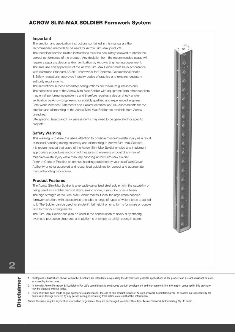
Product FeaturesThe Acrow Slim-Max Soldier is a versatile galvanised steel soldier with the capability of
being used as a soldier, vertical shore, raking shore, turnbuckle or as a beam.
The high strength of the Slim-Max Soldier makes it ideal for large crane handled
formwork shutters with accessories to enable a range of types of walers to be attached
to it. The Soldier can be used for single lift, full height or jump forms for single or double
face formwork arrangements.
The Slim-Max Soldier can also be used in the construction of heavy duty shoring,
overhead protection structures and platforms or simply as a high strength beam.
Product Description Code No. Mass kg (nom.)
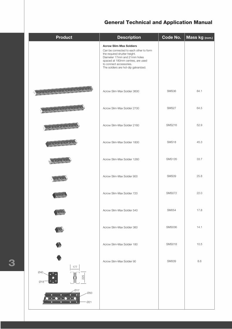
Acrow Slim-Max Soldiers
Can be connected to each other to form the required shutter height. Diameter 17mm and 21mm holes spaced at 180mm centres, are used to connect accessories.The soldiers are hot-dip galvanized.
Acrow Slim-Max Soldier 3600
Acrow Slim-Max Soldier 2700
Acrow Slim-Max Soldier 2160
Acrow Slim-Max Soldier 1800
Acrow Slim-Max Soldier 1260
Acrow Slim-Max Soldier 900
Acrow Slim-Max Soldier 720
Acrow Slim-Max Soldier 540
Acrow Slim-Max Soldier 360
Acrow Slim-Max Soldier 180
Acrow Slim-Max Soldier 90
SMS36
SMS27
SMS216
SMS18
SMS126
SMS09
SMS072
SM054
SMS036
SMS018
SM009
84.1
64.5
52.9
45.3
33.7
25.8
22.0
17.8
14.1
10.5
8.6
General Technical and Application Manual
3Ø40
177
225
Ø18
Ø50
Ø21
Ø17
ACROW SLIM-MAX SOLDIER Formwork System
Product Description Code No. Mass kg (nom.)
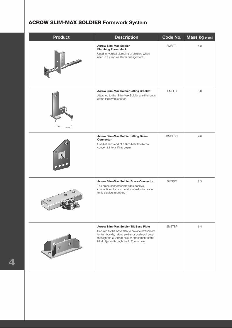
Acrow Slim-Max Soldier Plumbing Thrust Jack
Used for vertical plumbing of soldiers when used in a jump wall form arrangement.
Acrow Slim-Max Soldier Lifting Bracket
Attached to the Slim-Max Soldier at either ends of the formwork shutter.
Acrow Slim-Max Soldier Lifting Beam Connector
Used at each end of a Slim-Max Soldier to convert it into a lifting beam.
Acrow Slim-Max Soldier Brace Connector
The brace connector provides positive connection of a horizontal scaffold tube brace to tie soldiers together.
Acrow Slim-Max Soldier Tilt Base Plate
Secured to the base slab to provide attachment for turnbuckle, raking soldier or push-pull prop through the Ø 21mm hole or attachment of the RH/LH jacks through the Ø 26mm hole.
SMSPTJ
SMSLB
SMSLBC
SMSBC
SMSTBP
6.8
5.0
9.0
2.3
6.4
4
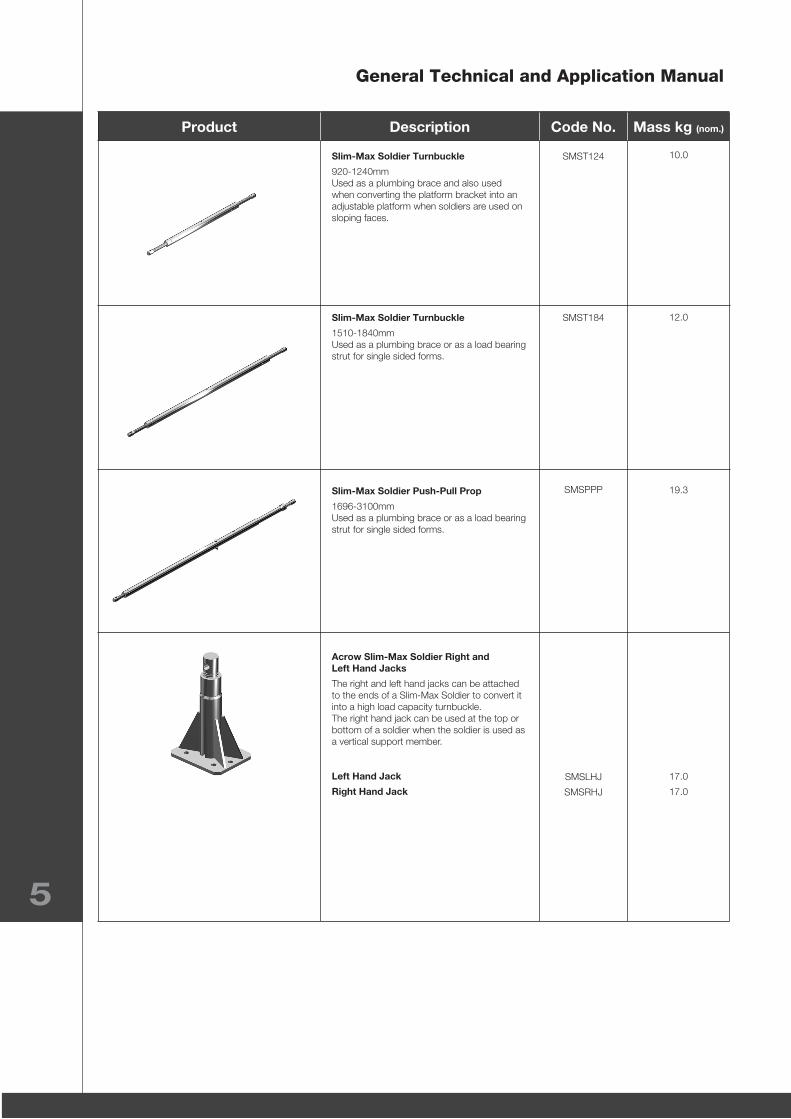
Product Description Code No. Mass kg (nom.)
Slim-Max Soldier Turnbuckle
920-1240mmUsed as a plumbing brace and also used when converting the platform bracket into an adjustable platform when soldiers are used on sloping faces.
Slim-Max Soldier Turnbuckle
1510-1840mmUsed as a plumbing brace or as a load bearing strut for single sided forms.
Slim-Max Soldier Push-Pull Prop
1696-3100mmUsed as a plumbing brace or as a load bearing strut for single sided forms.
Acrow Slim-Max Soldier Right and Left Hand Jacks
The right and left hand jacks can be attached to the ends of a Slim-Max Soldier to convert it into a high load capacity turnbuckle.The right hand jack can be used at the top or bottom of a soldier when the soldier is used as a vertical support member.
Left Hand Jack
Right Hand Jack
SMST124
SMST184
SMSPPP
SMSLHJ
SMSRHJ
10.0
12.0
19.3
17.0
17.0
General Technical and Application Manual
5
ACROW SLIM-MAX SOLDIER Formwork System
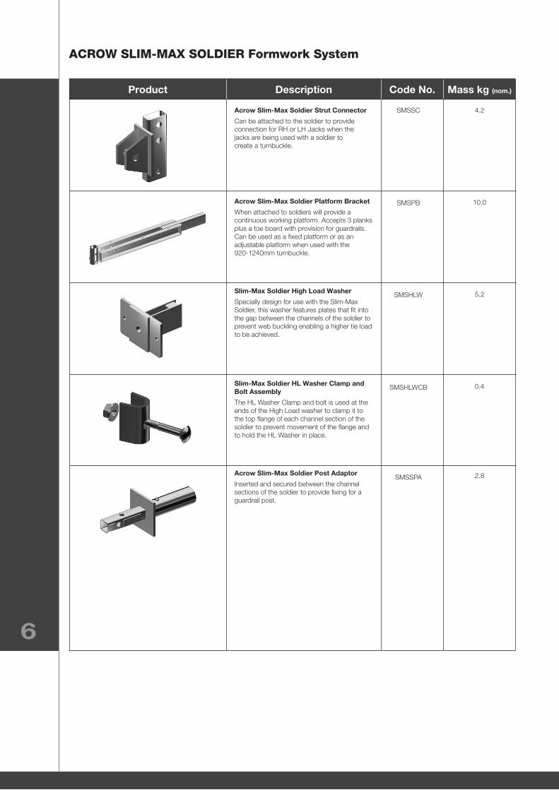
Product Description Code No. Mass kg (nom.)
Acrow Slim-Max Soldier Strut Connector
Can be attached to the soldier to provide connection for RH or LH Jacks when the jacks are being used with a soldier to create a turnbuckle.
Acrow Slim-Max Soldier Platform Bracket
When attached to soldiers will provide a continuous working platform. Accepts 3 planks plus a toe board with provision for guardrails.Can be used as a fixed platform or as an adjustable platform when used with the 920-1240mm turnbuckle.
Slim-Max Soldier High Load Washer
Specially design for use with the Slim-Max Soldier, this washer features plates that fit into the gap between the channels of the soldier to prevent web buckling enabling a higher tie load to be achieved.
Slim-Max Soldier HL Washer Clamp and Bolt Assembly
The HL Washer Clamp and bolt is used at the ends of the High Load washer to clamp it to the top flange of each channel section of the soldier to prevent movement of the flange and to hold the HL Washer in place.
Acrow Slim-Max Soldier Post Adaptor
Inserted and secured between the channel sections of the soldier to provide fixing for a guardrail post.
SMSSC
SMSPB
SMSHLW
SMSHLWCB
SMSSPA
4.2
10.0
5.2
0.4
2.8
6
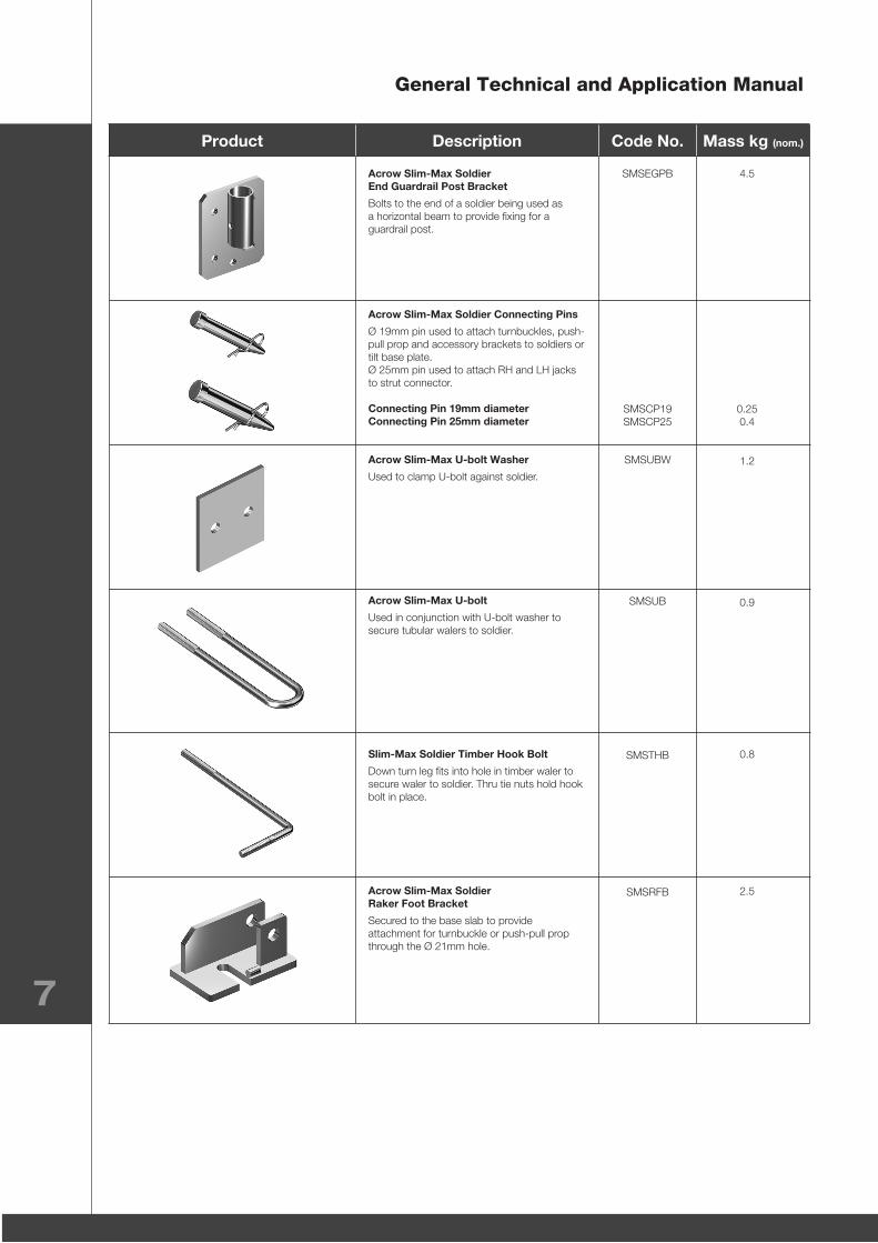
Product Description Code No. Mass kg (nom.)
Acrow Slim-Max Soldier End Guardrail Post Bracket
Bolts to the end of a soldier being used as a horizontal beam to provide fixing for a guardrail post.
Acrow Slim-Max Soldier Connecting Pins
Ø 19mm pin used to attach turnbuckles, push-pull prop and accessory brackets to soldiers or tilt base plate.Ø 25mm pin used to attach RH and LH jacks to strut connector.
Connecting Pin 19mm diameter Connecting Pin 25mm diameter
Acrow Slim-Max U-bolt Washer
Used to clamp U-bolt against soldier.
Acrow Slim-Max U-bolt
Used in conjunction with U-bolt washer to secure tubular walers to soldier.
Slim-Max Soldier Timber Hook Bolt
Down turn leg fits into hole in timber waler to secure waler to soldier. Thru tie nuts hold hook bolt in place.
Acrow Slim-Max Soldier Raker Foot Bracket
Secured to the base slab to provide attachment for turnbuckle or push-pull prop through the Ø 21mm hole.
SMSEGPB
SMSCP19 SMSCP25
SMSUBW
SMSUB
SMSTHB
SMSRFB
4.5
0.25 0.4
1.2
0.9
0.8
2.5
General Technical and Application Manual
7
ACROW SLIM-MAX SOLDIER Formwork System
8
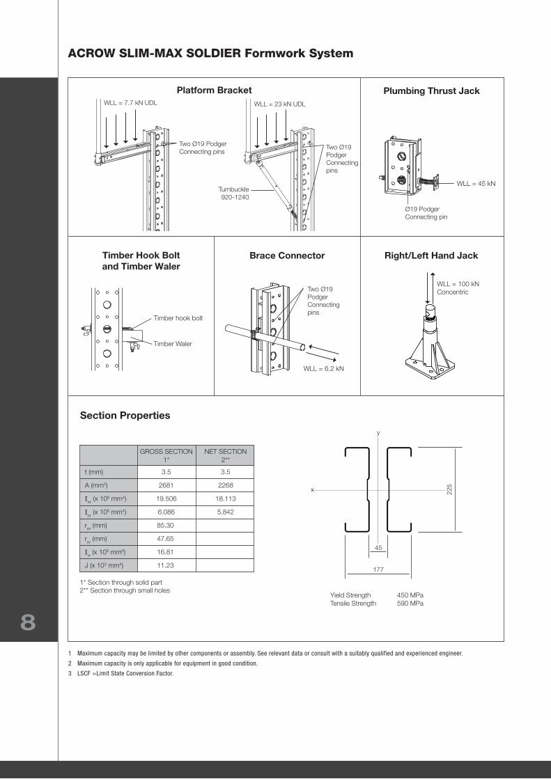
Right/Left Hand Jack
Plumbing Thrust Jack
Timber Hook Bolt and Timber Waler
Platform Bracket
Brace Connector
Section Properties
1 Maximum capacity may be limited by other components or assembly. See relevant data or consult with a suitably qualified and experienced engineer.
2 Maximum capacity is only applicable for equipment in good condition.
3 LSCF =Limit State Conversion Factor.
Yield Strength 450 MPaTensile Strength 590 MPa
GROSS SECTION NET SECTION 1* 2**
t (mm) 3.5 3.5
A (mm2) 2681 2268
Ixx (x 106 mm4) 19.506 18.113
Iyy (x 106 mm4) 6.086 5.842
rxx (mm) 85.30
ryy (mm) 47.65
Iw (x 109 mm6) 16.81
J (x 103 mm4) 11.23
1* Section through solid part2** Section through small holes
WLL = 45 kN
WLL = 6.2 kN
Ø19 Podger Connecting pin
Two Ø19 Podger Connecting pins
Two Ø19 Podger Connecting pins
Turnbuckle 920-1240
WLL = 7.7 kN UDL WLL = 23 kN UDL
Two Ø19 Podger Connecting pins
Timber hook bolt
Timber Waler
WLL = 100 kNConcentric
45
y
x
177
225
General Technical and Application Manual
9
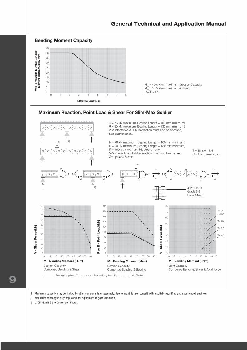
Bending Moment Capacity
1 Maximum capacity may be limited by other components or assembly. See relevant data or consult with a suitably qualified and experienced engineer.
2 Maximum capacity is only applicable for equipment in good condition.
3 LSCF =Limit State Conversion Factor.
M - Bending Moment (kNm)
Section CapacityCombined Bending & Shear
M - Bending Moment (kNm)
Section CapacityCombined Bending & Bearing
M - Bending Moment (kNm)
Joint CapacityCombined Bending, Shear & Axial Force
V -
She
ar F
orc
e (k
N)
P o
r R
- P
oin
t Lo
ad (k
N)
V -
She
ar F
orc
e (k
N)
Maximum Reaction, Point Load & Shear For Slim-Max Soldier
R = 76 kN maximum (Bearing Length = 100 mm minimum)R = 80 kN maximum (Bearing Length = 130 mm minimum)V-M interaction & R-M interaction must also be checked, See graphs below.
P = 76 kN maximum (Bearing Length = 100 mm minimum)P = 80 kN maximum (Bearing Length = 130 mm minimum)P = 160 kN maximum (HL Washer only)V-M interaction & P-M interaction must also be checked, See graphs below.
T = Tension, kNC = Compression, kN
4 M16 x 50 Grade 8.8 Bolts & Nuts
Mxx = 40.0 kNm maximum, Section CapacityMyy = 15.5 kNm maximum @ JointLSCF =1.5
R
R
P
PV
V V VV V
V TT
CC
M M M M M M
0 1 2 3 4 5 6 7 8
Effective Length, m
Max
Per
mis
sib
le M
emb
er B
end
ing
M
om
ent
abo
ut X
X a
xis,
kN
m
45
40
35
30
25
20
15
10
5
0
0 5 10 15 20 25 30 35 40
100
90
80
70
60
50
40
30
20
10
00 5 10 15 20 25 30 35 40 0 2 4 6 8 10 12 14 16 18
180
160
140
120
100
80
60
40
20
0
80
70
60
50
40
30
20
10
0
T= 0C 40
T=10
T= 20
T= 40
^
Bearing Length = 100 Bearing Length = 130 HL Washer
ACROW SLIM-MAX SOLDIER Formwork System
10
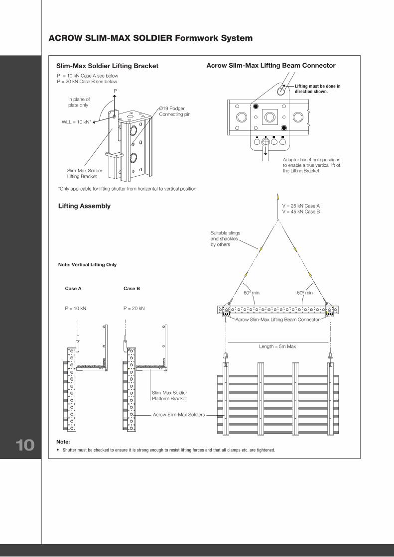
Acrow Slim-Max Lifting Beam Connector
Lifting must be done in direction shown.
Slim-Max Soldier Lifting Bracket
Lifting Assembly
P = 10 kN Case A see belowP = 20 kN Case B see below
Ø19 Podger Connecting pin
In plane of plate only
P
WLL = 10 kN*
Slim-Max SoldierLifting Bracket
*Only applicable for lifting shutter from horizontal to vertical position.
Adaptor has 4 hole positions to enable a true vertical lift of the Lifting Bracket
Slim-Max SoldierPlatform Bracket
P = 10 kN
Case A
Note: Vertical Lifting Only
P = 20 kN
Case B
Acrow Slim-Max Soldiers
Note:
• Shutter must be checked to ensure it is strong enough to resist lifting forces and that all clamps etc. are tightened.
Length = 5m Max
Acrow Slim-Max Lifting Beam Connector
Suitable slingsand shacklesby others
V = 25 kN Case AV = 45 kN Case B
600 min 600 min
General Technical and Application Manual
11
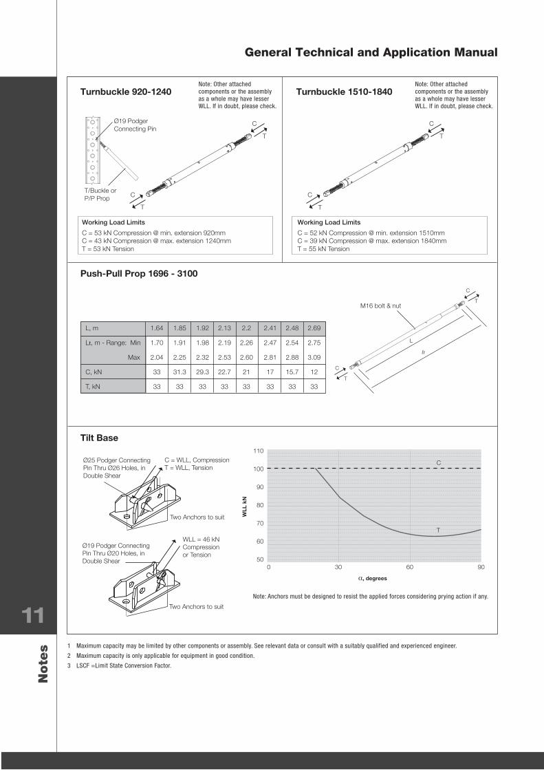
Push-Pull Prop 1696 - 3100
Tilt Base
M16 bolt & nut
1 Maximum capacity may be limited by other components or assembly. See relevant data or consult with a suitably qualified and experienced engineer.
2 Maximum capacity is only applicable for equipment in good condition.
3 LSCF =Limit State Conversion Factor.
Note
s
Turnbuckle 920-1240 Turnbuckle 1510-1840
Working Load Limits
C = 53 kN Compression @ min. extension 920mmC = 43 kN Compression @ max. extension 1240mmT = 53 kN Tension
Working Load Limits
C = 52 kN Compression @ min. extension 1510mmC = 39 kN Compression @ max. extension 1840mmT = 55 kN Tension
Note: Other attached components or the assembly as a whole may have lesser WLL. If in doubt, please check.
Note: Other attached components or the assembly as a whole may have lesser WLL. If in doubt, please check.
Note: Anchors must be designed to resist the applied forces considering prying action if any.
Ø19 Podger Connecting Pin
T/Buckle or P/P Prop
T
T
C
C
T
T
C
C
lt
L
T
T
C
C
L, m 1.64 1.85 1.92 2.13 2.2 2.41 2.48 2.69
Lt, m - Range: Min 1.70 1.91 1.98 2.19 2.26 2.47 2.54 2.75
Max 2.04 2.25 2.32 2.53 2.60 2.81 2.88 3.09
C, kN 33 31.3 29.3 22.7 21 17 15.7 12
T, kN 33 33 33 33 33 33 33 33
Two Anchors to suit
WLL = 46 kN Compression or Tension
Ø19 Podger Connecting Pin Thru Ø20 Holes, in Double Shear
Two Anchors to suit
Ø25 Podger Connecting Pin Thru Ø26 Holes, in Double Shear
C = WLL, CompressionT = WLL, Tension
0 30 60 90
110
100
90
80
70
60
50
C
T
α, degrees
WLL
kN

ACROW SLIM-MAX SOLDIER Formwork System
12
Slim-Max Raker Foot Bracket
Soldier Pin Holes Strut Connector
Anchor to suit.
Ø19 Podger Connecting Pin Thru Ø21 Holes, in Double Shear
C = WLL, CompressionT = WLL, Tension
Note: Anchors must be designed to resist the applied forces considering prying action.
1 WLL = Working Load Limit, applies to maximum capacity of specified component in application as shown and not assembly as a whole. If in doubt please ask.
2 Maximum capacity may be limited by other components or assembly. See relevant data or consult with a suitably qualified and experienced engineer.
3 Maximum capacity is only applicable for equipment in good condition.
4. Limit State Conversion Factor = 1.5.Note
s
WLL = 54 kN
Ø16 Podger Connecting Pin Thru Ø17 Holes in Double Shear
WLL = 66 kN
Ø19 Podger Connecting Pin Thru Ø21 Holes in Double Shear
Strut Connector
Ø25 Podger Connecting Pin Thru Ø27 Holes
C = WLL, CompressionT = WLL, Tension
C
T
α
x
2-Ø19 Podger Connecting Pins Thru Ø21 Holes
A = distance between pins
C
α
T
0 15 30 45 60 75
60
50
40
30
20
10
0
C
T
WLL
kN
α, degrees
0 30 60 90
120
110
100
90
80
70
60
50
α, degrees
Tension, A = 180
Tension, A = 120
Compression, A = 180
Compression, A = 120WLL
kN
A = Distance between pins. Refer above.
1
2
3
4
3
41
2
General Technical and Application Manual
13
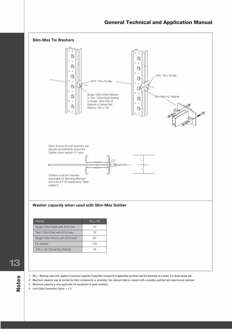
Slim-Max Tie Washers
Washer capacity when used with Slim-Max Soldier
1 WLL = Working Load Limit, applies to maximum capacity of specified component in application as shown and not assembly as a whole. If in doubt please ask.
2 Maximum capacity may be limited by other components or assembly. See relevant data or consult with a suitably qualified and experienced engineer.
3 Maximum capacity is only applicable for equipment in good condition.
4. Limit State Conversion Factor = 1.5.Note
s
Ø20 Thru Tie Bar
Slim-Max HL Washer
Ø15 Thru Tie Bar
Single 125x100x8 Washer or Twin 125x100x8 Washer or Single 130x130x12 Washer or Swivel Nut Washer 120 x 120
Note: Ensure tie and washer/s are placed symmetrically about the Soldier cross section Y-Y axis.
Soldiers must be checked separately for Bending Moment and V-M & P-M interactions. Refer pages 9.
Washer WLL, kN
Single 125x100x8 with Ø18 hole 50
Twin 125x100x8 with Ø18 hole 76
Single 130x130x12 with Ø18 hole 80
HL washer 160
120 x 120 Swivel Nut Washer 78
==
ACROW SLIM-MAX SOLDIER Formwork System
14
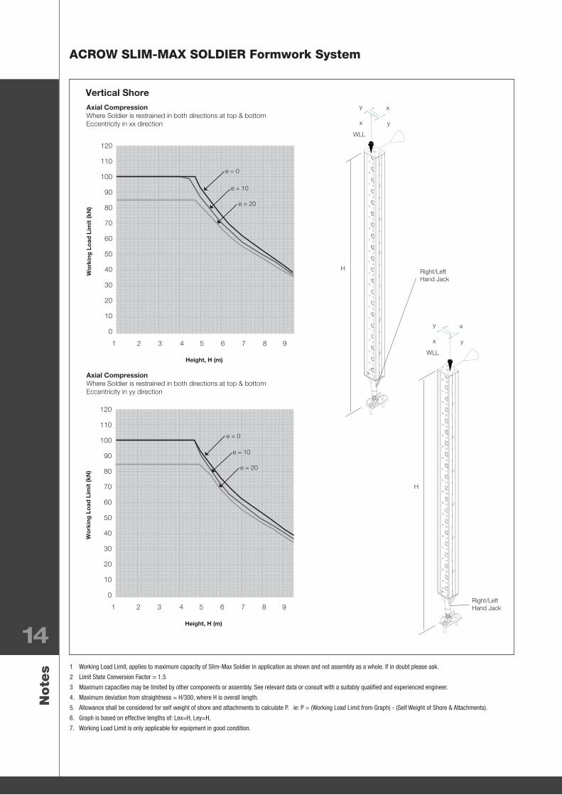
Vertical Shore
1 Working Load Limit, applies to maximum capacity of Slim-Max Soldier in application as shown and not assembly as a whole. If in doubt please ask.
2 Limit State Conversion Factor = 1.5
3 Maximum capacities may be limited by other components or assembly. See relevant data or consult with a suitably qualified and experienced engineer.
4. Maximum deviation from straightness = H/300, where H is overall length.
5. Allowance shall be considered for self weight of shore and attachments to calculate P. ie: P = (Working Load Limit from Graph) - (Self Weight of Shore & Attachments).
6. Graph is based on effective lengths of: Lex=H, Ley=H,
7. Working Load Limit is only applicable for equipment in good condition.
Note
s
Right/Left Hand Jack
WLL
x
x
y
y
H
Right/Left Hand Jack
WLL
x
x
y
y
H
120
110
100
90
80
70
60
50
40
30
20
10
0
1 2 3 4 5 6 7 8 9
Wo
rkin
g L
oad
Lim
it (k
N)
Height, H (m)
120
110
100
90
80
70
60
50
40
30
20
10
0
1 2 3 4 5 6 7 8 9
Wo
rkin
g L
oad
Lim
it (k
N)
Height, H (m)
Axial CompressionWhere Soldier is restrained in both directions at top & bottom Eccentricity in xx direction
Axial CompressionWhere Soldier is restrained in both directions at top & bottom Eccentricity in yy direction
e = 0
e = 0
e = 10
e = 10
e = 20
e = 20
General Technical and Application Manual
15
P
Right/Left Hand Jack
L
P
α
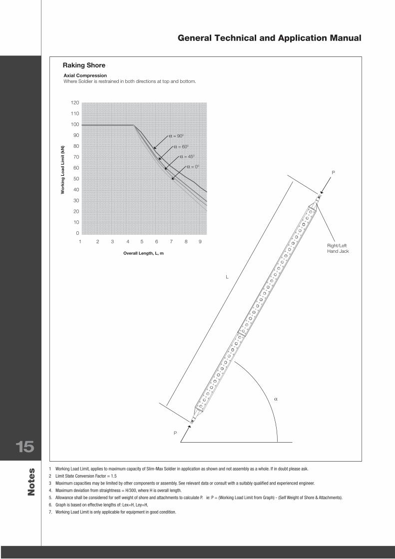
Raking Shore
1 Working Load Limit, applies to maximum capacity of Slim-Max Soldier in application as shown and not assembly as a whole. If in doubt please ask.
2 Limit State Conversion Factor = 1.5
3 Maximum capacities may be limited by other components or assembly. See relevant data or consult with a suitably qualified and experienced engineer.
4. Maximum deviation from straightness = H/300, where H is overall length.
5. Allowance shall be considered for self weight of shore and attachments to calculate P. ie: P = (Working Load Limit from Graph) - (Self Weight of Shore & Attachments).
6. Graph is based on effective lengths of: Lex=H, Ley=H,
7. Working Load Limit is only applicable for equipment in good condition.
Note
s
120
110
100
90
80
70
60
50
40
30
20
10
0
1 2 3 4 5 6 7 8 9
Wo
rkin
g L
oad
Lim
it (k
N)
Overall Length, L, m
Axial CompressionWhere Soldier is restrained in both directions at top and bottom.
α = 900
α = 600
α = 450
α = 00
Formwork
Scaffolding
Industrial & Mining Scaffolding
Phone: 1300 138 362or contact your business development manager.www.acrow.com.au
Contact
Up
dated
Octob
er 2012