acejedi’s “dammit grogu does something” mod
TRANSCRIPT

Neither creator nor writer receive any compensation for the recommendations to any products linked in this document. Neither creator nor writer are affiliated with Amazon, Disney or Hasbro.
AceJedi’s “DAMMIT GROGU DOES SOMETHING” Mod
WARNING, THIS DOCUMENT IS FOR INFORMATIONAL PURPOSES ONLY
IMPORTANT, READ ALL INSTRUCTIONS CAREFULLY, FAILURE TO DO SO MAY CAUSE PERSONAL
INJURY OR DAMAGE TO PRODUCT AND/OR PROPERTY. CREATERS ARE FREE AND CLEAR OF ALL
IMPLIED OR NOT LIABLE FOR ANY DAMAGE TO PERSONAL ELECTRONICS FROM THIS
MODIFICATION. ANY MODIFICATION DONE MIGHT VOID YOUR FACTORY WARRANTY.
AGAIN, THIS DOCUMENT IS FOR INFORMATIONAL PURPOSES ONLY
SKILL LEVEL - ADVANCED
Neither creator nor writer receive any compensation for the recommendations to any products linked in this document. Neither creator nor writer are affiliated with Amazon, Disney or Hasbro.
PARTS NEEDED PRIOR TO INSTALLATION:
1. Star Wars – The Mandalorian The Child Hasbro 7.2” Animatronic Toy
2. AceJedi Lit Grogu Necklace (Optional)
a. (2 Qty) 5v small colored LED’s
b. 22-gauge wire 18”
c. 5-pin Stern style lightboard connector
3. AceJedi Custom Wiring Kit. (Optional)
a. SUBALIGU 5pcs 12V Photoresistor Sensor Relay Module Car Light Automatic
Control Switch with Cable
b. EBOOT 20 AWG JST Plug Connector 2 Pin Male Female Plug Connector Cable
Wire for LED Lamp Strip RC Toys Battery, 10 Pairs
c. XFFCSEC 10pcs 5x20mm Fuse Holder Inline Screw Type With 18 AWG wire +
150pcs Quick Blow Glass Tube Fuse Assorted Kit Amp 250V
0.1A,0.2A,0.5A,1A,2A,3A,5A,8A,10A,15A,5x20mm, 0.5A,1A,5A,10A,15A,6x30mm
d. 650pcs Heat Shrink Tubing Black innhom Heat Shrink Tube Wire Shrink Wrap UL
Approved Ratio 2:1 Electrical Cable Wire Kit Set Long Lasting Insulation
Protection, Safe and Easy, Eco-Friendly Material
e. AIRIC Female Spade Connector 16-14 Gauge 100PCS Nylon Fully Insulated
Female Wire Quick Disconnects Spade Terminal Connectors Blue
f. Kuject 240Pcs T Tap Wire Connectors, 24-10 AWG Quick Splice Electric Wire
Terminals, Self-Stripping Insulated Male Quick Disconnect Spade Terminals
Assortment Kit with Case
g. Molex (2-Circuits) Male & Female Receptacle Plug, w/Terminal sockets w/18-24
AWG Standard .062" Pins, Pitch 3.68mm (Pack of 6 Set)
h. TUOFENG 22 awg Solid Wire-Solid Wire Kit-6 Different Colored 30 Feet spools
22 Gauge Jumper Wire- Hook up Wire Kit
i. 6 Pin female connector for Stern cabinet node 12v
j. 3M Double sided tape (black)
k. Hem adhesive
4. Rear Grogu Backboard Mounting kit (only available in the AceJedi Custom Wiring Kit)
5. Relay Driver Bracket and Stand-offs Kit (only available in the AceJedi Custom Wiring Kit)
TOOLS NEEDED FOR BUILD:
1. Dremel Tool with cutting wheel and fine sanding tip
2. ¼” nut driver
3. Small Phillips screwdriver
4. Wire strippers / crimpers
5. Soldering Iron (not required with the AceJedi Custom Wiring Kit)
6. Solder and Flux (not required with the AceJedi Custom Wiring Kit)
7. Molex Crimps (not required with the AceJedi Custom Wiring Kit)
8. Zip ties (not required with the AceJedi Custom Wiring Kit)

Neither creator nor writer receive any compensation for the recommendations to any products linked in this document. Neither creator nor writer are affiliated with Amazon, Disney or Hasbro.
9. Hot Glue Gun (not required with the AceJedi Custom Wiring Kit)
10. Black Sharpie
11. Small tape measure
INSTALLATION INSTRUCTIONS:
Congratulations, THIS IS THE WAY. Let’s get started
1. Grogu Body Disassembly.
a. Take apart the Hasbro Toy Grogu starting with the feet. (screws not needed)
b. Remove the three AA batteries
c. Remove Grogu’s Cape and put it aside for later use.
d. Remove 6 screws on the back of Grogu. (we will only use 4 screws)
e. Remove the back piece (careful his right arm will fall out when removed)
f. Pull out battery tray from the bottom and unscrew the on/off switch from the
battery tray.
g. Cut the red and the black wire at the battery tray (not used)
h. Carefully remove left arm by unlocking green center pin on arm shaft from small
gray drive pin. Take notice of the keyed configuration, it is removed and
installed only one way.
i. Remove 2 screws, speaker and speaker bracket (not needed)
j. Remove 1 screw on each side of the gray drive pin. This frees the head from the
clam shell body. (screws needed, place the head to the side)
2. Grogu Body Modification
a. Use a Sharpie to draw a black line on the inside of the chest piece.
b. Use a Dremel tool to cut the chest piece in half. Do not cut off the lower posts.
There should be 6 posts after the cut is made. This is critical to mount and
stabilize Grogu while he is moving.
Neither creator nor writer receive any compensation for the recommendations to any products linked in this document. Neither creator nor writer are affiliated with Amazon, Disney or Hasbro.
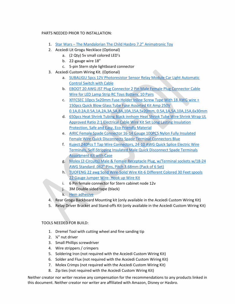
c. Use a sharpie to draw a black line on the inside of the back piece.
d. Use a Dremel tool to cut the back in half. There should be 4 receiving posts after
the cut is made. These four posts will connect to the top 4 posts on the chest
piece.

Neither creator nor writer receive any compensation for the recommendations to any products linked in this document. Neither creator nor writer are affiliated with Amazon, Disney or Hasbro.
3. Grogu Head Disassembly
a. Remove the two screws on the back of Grogu’s head
b. Removing Grogu’s Rear Skull can be a little tricky.
i. Turn his head upside down and place your right hand over his face with
your right thumb on top of his head. (Don’t touch white nylon assembly)
ii. Place your left hand on the back of his head wth your left thumb on top
of his head. (Don’t touch white nylon assembly)
iii. Pull the neck apart outward leaving your thumbs on Grogu’s head and it
will pop open.
c. Take a break. Get a Drink. Use the restroom. Eat.
d. Removing Grogu’s ears. (Start with right ear)
i. Place Grogu face down in your left hand so you’re looking at the back of
his head.
ii. GENTLY lift the bottom of the ear off the green post until it loosens.
iii. GENTLY wiggle the top of the ear off the green post.
iv. GENTLY pull the ear to the right away from the head exposing the gray
shaft.
v. Perform steps i. -iv. To remove the left ear. It should look like the
pictures below when complete.
Neither creator nor writer receive any compensation for the recommendations to any products linked in this document. Neither creator nor writer are affiliated with Amazon, Disney or Hasbro.
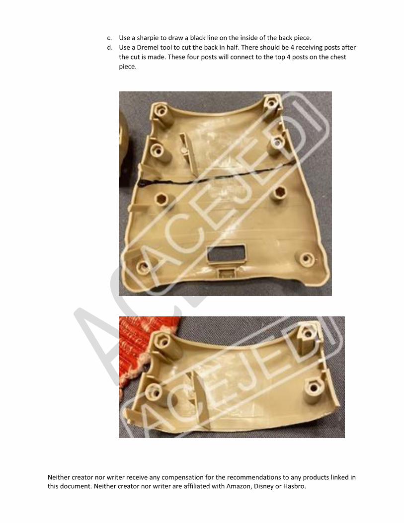
4. Remove the 2 screws on the very top back of the head.
5. GENTLY remove Grogu’s Face off of the white assembly.
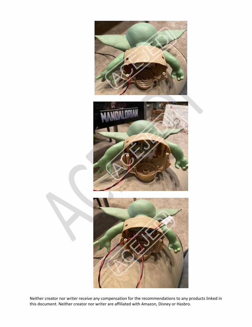
6. Next, we will remove the circuit board and all wiring except for the motor and two wires
on the top of Grogu’s head. Refer to the pictures below.

Neither creator nor writer receive any compensation for the recommendations to any products linked in this document. Neither creator nor writer are affiliated with Amazon, Disney or Hasbro.
7. Use two tap wire connectors to tie onto the black and red wire coming off Groku’s head.
(included in AceJedi’s Custom Wiring Kit, if you have this skip steps 9, 10 and 12)
8. Cut a red and black wire anywhere from 24”-36”
9. Attach 1 female spade connector to one end of each wire.
10. Plug the spade connecters into the tap wire connectors.
11. Add a 2 pin molex connector to the other end of the wires. This completes Grogu’s
wiring.
12. Reassemble the head in reverse starting at step #5 and ending at step #3. Route the
wiring through the original guide clips down through the neck staying clear of the
moving parts.
Neither creator nor writer receive any compensation for the recommendations to any products linked in this document. Neither creator nor writer are affiliated with Amazon, Disney or Hasbro.
Neither creator nor writer receive any compensation for the recommendations to any products linked in this document. Neither creator nor writer are affiliated with Amazon, Disney or Hasbro.
Neither creator nor writer receive any compensation for the recommendations to any products linked in this document. Neither creator nor writer are affiliated with Amazon, Disney or Hasbro.
13. Grogu’s head and body are now complete. Time to take another break. You’re almost
done.
14. Remove old Grogu from pinball playfield by removing (2 Qty) screws with a ¼” nut driver
on the back panel of the playfield (you will need to remove glass and pull playfield out
to the standoffs).
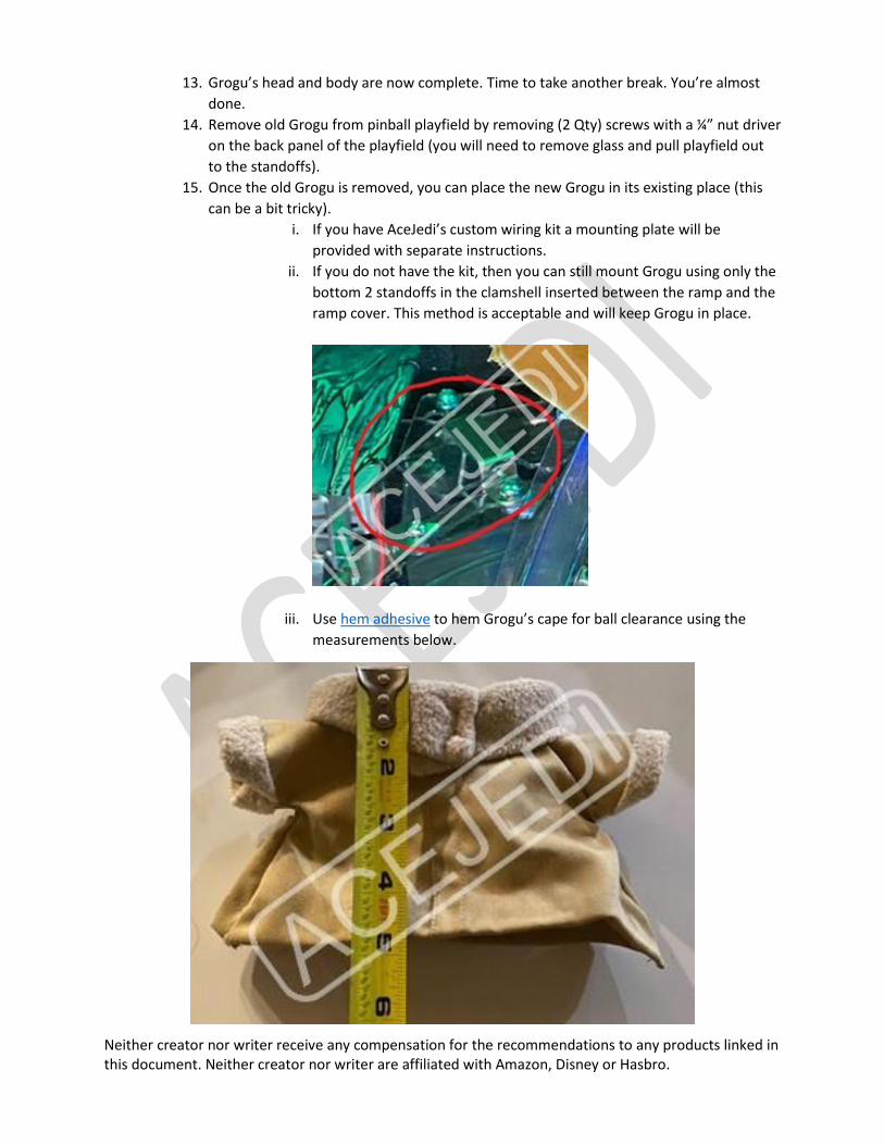
15. Once the old Grogu is removed, you can place the new Grogu in its existing place (this
can be a bit tricky).
i. If you have AceJedi’s custom wiring kit a mounting plate will be
provided with separate instructions.
ii. If you do not have the kit, then you can still mount Grogu using only the
bottom 2 standoffs in the clamshell inserted between the ramp and the
ramp cover. This method is acceptable and will keep Grogu in place.
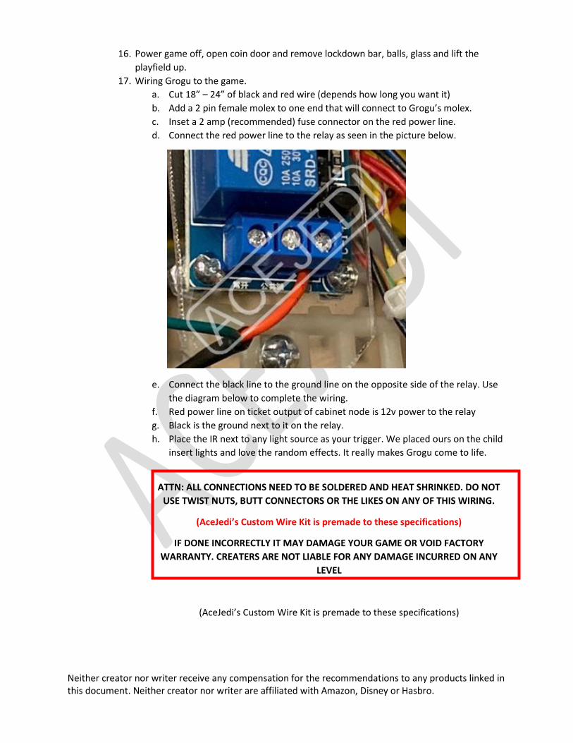
iii. Use hem adhesive to hem Grogu’s cape for ball clearance using the
measurements below.
Neither creator nor writer receive any compensation for the recommendations to any products linked in this document. Neither creator nor writer are affiliated with Amazon, Disney or Hasbro.
16. Power game off, open coin door and remove lockdown bar, balls, glass and lift the
playfield up.
17. Wiring Grogu to the game.
a. Cut 18” – 24” of black and red wire (depends how long you want it)
b. Add a 2 pin female molex to one end that will connect to Grogu’s molex.
c. Inset a 2 amp (recommended) fuse connector on the red power line.
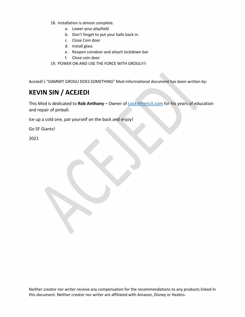
d. Connect the red power line to the relay as seen in the picture below.
e. Connect the black line to the ground line on the opposite side of the relay. Use
the diagram below to complete the wiring.
f. Red power line on ticket output of cabinet node is 12v power to the relay
g. Black is the ground next to it on the relay.
h. Place the IR next to any light source as your trigger. We placed ours on the child
insert lights and love the random effects. It really makes Grogu come to life.
ATTN: ALL CONNECTIONS NEED TO BE SOLDERED AND HEAT SHRINKED. DO NOT
USE TWIST NUTS, BUTT CONNECTORS OR THE LIKES ON ANY OF THIS WIRING.
(AceJedi’s Custom Wire Kit is premade to these specifications)
IF DONE INCORRECTLY IT MAY DAMAGE YOUR GAME OR VOID FACTORY
WARRANTY. CREATERS ARE NOT LIABLE FOR ANY DAMAGE INCURRED ON ANY
LEVEL
(AceJedi’s Custom Wire Kit is premade to these specifications)

Neither creator nor writer receive any compensation for the recommendations to any products linked in this document. Neither creator nor writer are affiliated with Amazon, Disney or Hasbro.
Neither creator nor writer receive any compensation for the recommendations to any products linked in this document. Neither creator nor writer are affiliated with Amazon, Disney or Hasbro.
18. Installation is almost complete.
a. Lower your playfield
b. Don’t forget to put your balls back in.
c. Close Coin door
d. Install glass
e. Reopen coindoor and attach lockdown bar
f. Close coin door
19. POWER ON AND USE THE FORCE WITH GROGU!!!
AceJedi’s “DAMMIT GROGU DOES SOMETHING” Mod informational document has been written by:
KEVIN SIN / ACEJEDI
This Mod is dedicated to Rob Anthony – Owner of LockWhenLit.com for his years of education
and repair of pinball.
Ice up a cold one, pat yourself on the back and enjoy!
Go SF Giants!
2021