abc ngineering final report - university of texas at san...
TRANSCRIPT

ME 4813 SENIOR DESIGN 2
ABC Ngineering
Final Report
Date Submitted: 07 December 2016
Time: 1700 hours
By:
Noel Cantu
James Crisler
Bianca Dumlao
Aspen Meineke
In Partial Fulfillment for the Requirements of Senior Design 2
University of Texas at San Antonio Department of Mechanical Engineering.

Abstract
When NASA sends rovers to Mars, traditional tires are unreliable due to the sharp and rugged
terrain of the planet. This is why it is important to study alternative methods of transportation
such as rimless wheels. Rimless wheels combine the ease and energy efficiency of a normal
wheel with the flexibility of legged locomotion. The purpose of the Roadrunner Robot 2 (RR2) is
to design a rimless wheeled robot capable of achieving a speed of 5 miles per hour and a turning
radius of 5 feet. A differential drive system was used with 10 spokes on each wheel to increase
the stability. Arduino Mega 2560, Xbee shield and Xbee antennas with a Zigbee protocol were
used to remotely control the robot. In testing the RR2 was able to achieve a minimum speed of 5
miles per hour while traveling straight. The RR2 was able to complete a 5-foot turning radius
and could be controlled from a distance of 50 feet. ABC Ngineering worked under the
mentorship of Dr. Pranav Bhounsule to design, analyze, build, and test the RR2 to further
research for the Robotics and Motions Laboratory at The University of Texas at San Antonio.

Table of Contents
Acronyms ......................................................................................................................................... i
1.0 Introduction ............................................................................................................................... 1
1.1 Importance of Proposed Research ................................................................................ 1
1.2 Rimmed Wheels ............................................................................................................ 2
1.3 Legged Locomotion ...................................................................................................... 2
1.4 Rimless Wheels ............................................................................................................. 2
1.5 Previous Research on Rimless Wheel Robots .............................................................. 3
2.0 Purpose ...................................................................................................................................... 3
3.0 Objectives ................................................................................................................................. 3
4.0 Engineering Design Specifications ........................................................................................... 4
4.1 Identification of Functional Requirements ................................................................... 4
4.2 Physical Specifications ................................................................................................. 4
4.3 Performance Specifications .......................................................................................... 5
5.0 Concepts and Selection ............................................................................................................. 6
5.1 Concept 1 – Independently Actuated Legs ................................................................... 6
5.2 Concept 2 – Steering Rack ............................................................................................ 8
5.3 Concept 3 – Varying Wheel Radius ........................................................................... 10
5.4 Final Concept Selection Method ................................................................................. 12
6.0 Final Design ............................................................................................................................ 13
6.1 Key Features ............................................................................................................... 13
6.2 Estimated Performance ............................................................................................... 17
6.3 Material Selection and Justification ............................................................................ 17
6.4 Assemblies and Parts .................................................................................................. 18
7.0 Prototype Fabrication .............................................................................................................. 19
7.1 Fabrication Methods ................................................................................................... 19
7.2 Prototype Fabrication Drawings ................................................................................. 19
7.3 Bill of Materials .......................................................................................................... 19

8.0 Prototype Tests ........................................................................................................................ 21
8.1 Test Plan Summary ..................................................................................................... 21
8.2 Test Setup ................................................................................................................... 21
8.3 Test Results ................................................................................................................. 22
9.0 Project Management ............................................................................................................... 24
9.1 Schedule ...................................................................................................................... 24
9.2 Financial Performance ................................................................................................ 29
10.0 Project Conclusions .............................................................................................................. 30
References ..................................................................................................................................... 31
Appendix A – Theory of Operations Manual .............................................................................. A1
Appendix B – Test Plan ................................................................................................................ B1
Appendix C – Test Report ............................................................................................................ C1
Appendix D – Design Drawings .................................................................................................. D1
Appendix E - Calculations ............................................................................................................ E1
List of Figures
Figure 1. Roadrunner Robot 1 ........................................................................................................ 1
Figure 2. Rimless Wheel [5] ........................................................................................................... 3
Figure 3. Concept 1 – Independently Actuated Legs ..................................................................... 6
Figure 4. Exploded View of Concept 1- Independently Actuated Legs ......................................... 7
Figure 5. Concept 2 - Steering Rack ............................................................................................... 8
Figure 6. Isometric View of Concept 3 – Varying Wheel Radius ................................................ 10
Figure 7: Exploded View of Concept 3 – Varying Wheel Radius ................................................ 11
Figure 8. Electrical System ........................................................................................................... 15
Figure 9. Software Diagram .......................................................................................................... 16
Figure 10. Roadrunner Robot 2 - Top Assembly .......................................................................... 18
Figure 11. Work Breakdown Schedule 1 ...................................................................................... 26
Figure 12. Work Breakdown Schedule 2 ...................................................................................... 26

Figure 13. Work Breakdown Schedule 3 ...................................................................................... 27
Figure 14. Work Breakdown Schedule 4 ...................................................................................... 27
Figure 15. Work Breakdown Schedule 5 ...................................................................................... 28
Figure 16. Work Breakdown Schedule 6 ...................................................................................... 28
Figure 17. Work Breakdown Schedule 7 ...................................................................................... 29
Figure 18. Work Breakdown Schedule 8 ...................................................................................... 29
Figure 19. Project Labor Cost ....................................................................................................... 29
Figure 20. Spoke Effectiveness .................................................................................................... E6
List of Tables
Table 1. Pugh Chart ...................................................................................................................... 12
Table 2. Bill of Materials .............................................................................................................. 19
Table 3: Compliance Matrix ......................................................................................................... 21
Table 4. Test T-1 Data .................................................................................................................. 22
Table 5. Test T-2 Data ................................................................................................................. 22
Table 6. Test T-3 Data ................................................................................................................. 22
Table 7. Test T-4 Data .................................................................................................................. 23
Table 8. Test T-5 Data ................................................................................................................. 23
Table 9. Test T-6 Data ................................................................................................................. 23
Table 10. Test T-7 Data ............................................................................................................... 23
Table 11. Moment of Inertia ......................................................................................................... E4
Table 12. Angular Velocity .......................................................................................................... E5
List of Equations
Equation 1. Concept 1 Turning Radius Calculations .................................................................... E1
Equation 2. Concept 2 Turning Radius Calculations .................................................................... E1
Equation 3. Concept 3 Turning Radius Calculations .................................................................... E2
Equation 4. Speed Calculations .................................................................................................... E2
Equations 5 and 6. Mass Moment of Inertia ................................................................................. E3
Equation 7. Angular Velocity ....................................................................................................... E3

Equation 8. Rotational Energy ...................................................................................................... E3
Equation 9. Estimated Battery Usage Calculations ...................................................................... E3
Equation 10. Schedule Variance ................................................................................................... E6
Equation 11. Cost Variance .......................................................................................................... E6
Equation 12. Schedule Performance Index ................................................................................... E7
Equation 13. Cost Performance Index .......................................................................................... E7
Equation 14. Cost Schedule Index ................................................................................................ E7

i
Acronyms
RR2 Roadrunner Robot 2
ESC Electronic Speed Control
ft Length/distance (feet)
in Length/distance (inches)
lbs Weight (pounds)
mph Linear speed (miles per hour)
rpm Angular speed (revolutions per minute)
IMU Inertial Measurement Unit
3D 3 Dimensional

1
1.0 Introduction
1.1 Importance of Proposed Research
Currently, the NASA Curiosity Rover is on Mars and there have been issues with the tires, due to
the rough terrain of the planet. Since Mars has sharp rocks like spikes, the tires can be “dented,
punctured and even torn,” which can cause damage to the rover [4]. This is why it is important to
study alternative methods of transportation, such as rimless wheels, which can travel over rocks
instead of going through them. The idea for this project is a continuation from a previous senior
design project that was completed at The University of Texas at San Antonio in Spring 2015.
The previous project was called the Roadrunner Robot 1 (RR1) and was designed by the team,
Force Over Area. The RR1 is a legged robot that achieves locomotion using a rimless wheel
design. ABC Ngineering will be designing the Roadrunner Robot 2, which will be a continuation
of the project done by Force Over Area.
Figure 1. Roadrunner Robot 1
The goal of this project is to further the research of rimless wheels, before this robot is able to be
utilized for other purposes. Possible applications of this robot include locomotion over rough
terrain such as a rover on land, lunar, or Martian surfaces.

2
1.2 Rimmed Wheels
Wheeled locomotion has been used for thousands of years for transportation. Rimmed Wheeled
locomotion is the preferred method of most transportation because of its simplicity, efficiency
and reliability. These traits has allowed for advancements of modern technology. Wheels reduce
the amount of friction caused when moving an object across a surface. This allows objects to be
moved using less energy. One of the deficiencies of a rimmed wheel is its ability to maneuver
over rough and uneven terrain.
1.3 Legged Locomotion
Legged locomotion combines the biology of a human walking with robotics and is the interaction
between the legs of the system and the environment [7]. When humans walk they show great
control over their movements and have the mobility to adjust moment when encountering an
obstacle in its path or adjust to irregular terrain. This method of movement shows great control
of movement, dexterity and stability [6]. However, it is still unknown how humans accomplish
this, which is why the study of legged locomotion is so imperative. Legged locomotion is used
for movement over rough or uneven terrain, which is quite difficult for traditional rigid robots.
1.4 Rimless Wheels
The rimless spoked wheel resembles legged locomotion and mimics the mechanical features of a
human walking such as foot collisions, falling-and-catching, and inverted pendulum behavior
when the spoke comes in contact with the ground [2]. The rimless wheel has a hub, which is
surrounded by spokes with a fixed angle between them. By being able to control the dynamic
motion of the robot, this could lead to a significant decrease in the energy required by the
system, which would increase the rimless wheels efficiency [1].

3
Figure 2. Rimless Wheel [5]
1.5 Previous Research on Rimless Wheel Robots
The previous design of this robot, the RR1, was capable of linear locomotion at a maximum
speed of 4.09 miles per hour. This design included two rimless wheels, 8 spokes on each wheel,
and a spring in each spoke to absorb the energy from the inelastic collision with the ground.
Rimless wheel robots are designed as rovers for rough terrain. Rovers often have wheels without
smooth, circular perimeters. The added capability of legged locomotion allows the rover to
facilitate traction and move about uneven surfaces [5].
2.0 Purpose
The purpose of the Roadrunner Robot 2 (RR2) is to design a rimless wheeled robot capable of
achieving a speed of 5 miles per hour and a turning radius of 5 feet. This robot will be used in the
Robotics and Motions Lab to further research focusing on legged locomotion.
3.0 Objectives
The objective of this project is to build and test a rimless wheeled robot capable of the desired
speed and turning radius. This will be fulfilled by turning in reports that will contain the detailed
design and drawings, analysis and calculations, fabrication plan, testing plan, and cost analysis to
ensure that the robot meets the specifications. Presentations will also be given, which will be
supplemented by PowerPoint slides and a poster.

4
4.0 Engineering Design Specifications
The specifications, below, were defined by our sponsor and mentor, Dr. Pranav Bhounsule. The
dimensions set were based on keeping the robot portable and able to be transported by the
average human.
4.1 Identification of Functional Requirements
The rimless wheeled robot must be able to achieve a speed of 5 miles per hour and a turning
radius of 5 feet. The structure of the robot must be strong enough to withstand the impact forces
absorbed at this speed. The robot must be able to be controlled by a remote control up to a
distance of 50 feet.
4.2 Physical Specifications
4.2.1 Dimensions
The dimensions of the robot will allow for portability and easy transportation. The robot
must be able to fit in the trunk of a car without being disassembled.
4.2.1.1 Radius
The radius of the robot’s wheel must not exceed 2 feet. The radius will be
measured from the center of the wheel hub to the outer radial edge of the wheel.
4.2.1.2 Width
The width of the robot must not exceed 1.5 feet. The width will be measured from
outer edge of each wheel hub.
4.2.2 Weight
The weight of the robot, including all its components, should not exceed 20 pounds.
4.2.3 Number of legs
The robot must consist of at least 3 legs per wheel.
4.2.4 Material
The material must be able to withstand the impact forces while the robot is operating.
4.2.5 Soldering
Soldering may be necessary to install electrical components.

5
4.3 Performance Specifications
4.3.1 Motor
The motor must be capable of producing a speed of 5 miles per hour.
4.3.2 Microcontroller
The microcontroller will be used to receive commands from the robot operator through
radio frequency. It will output speed and control commands to the motors through the
ESC (electronic speed controller).
4.3.2.1 Memory
The memory of the microcontroller must be large enough to store programs
needed to control the robot. It must have the necessary capacity to hold programs,
power the motor through current control, communicate between the remote
controller and the receiver, and record performance information on the robot.
4.3.2.2 Power Limitations
The microcontroller must be able to withstand voltages provided to it from all
other components.
4.3.3 Remote Control
The remote control must communicate with the robot from a distance exceeding 50 feet.
The remote control must have sufficient capabilities to stop the motor, increase motor
speed, decrease motor speed, and control turning operations.
4.3.4 Power Supply
A rechargeable battery will be used to power the robot.
4.3.5 Spring System
The legs of the robot must be able to absorb the forces from impact when hitting the
ground to minimize energy loss.
4.3.6 Turning
The robot must be able to turn at a radius of 5 feet. The radius will be measured from the
origin of the turn to the outer hub.
4.3.7 Speed
The robot must be able to travel straight at 5 miles per hour for 100 feet.

6
5.0 Concepts and Selection
5.1 Concept 1 – Independently Actuated Legs
5.1.1 Introduction
Differential drive is when the two wheels are controlled by different motors to allow for them to
operate at different speeds and it used for lighter robots. By having wheel speeds that are
independently controlled one wheel can be slowed down and the second wheel can increase in
speed allowing for the faster wheel to turn around the slower one. The proposed design is shown
in the figure below.
Figure 3. Concept 1 – Independently Actuated Legs

7
Figure 4. Exploded View of Concept 1- Independently Actuated Legs
5.1.2 Functionality
The two motors would be connected to an electronic speed controller, which would control the
speed of each wheel. A wireless transceiver module would be used in the robot and the wireless
remote controller to send data to each other. Each motor will be controlled with its own joystick
on the remote control. Moving the joystick up and down will get the wheels to move forward or
backwards. By increasing the speed of one of the motors and decreasing the speed of the second
this will allow for the robot to turn.
5.1.3 Specifications
This method must allow the robot to have a turning radius of 5 feet and a minimum speed of 5
mph.
5.1.4 Strengths
The method of differential drive has high mobility due to its pivot rotation and ability to turn in a
small space. It also can make a turning radius of 5 ft. and a speed of 5 mph, as shown in the
calculations in Appendix E. This design has an estimated cost of $1,209, which is $791 below
the budget of $2,000.

8
5.1.5 Weaknesses
With each motor being on a different axel, it may be difficult to keep each wheel out of phase
with each other to create the running effect. The additional spokes causes a slight increase in
cost, but is still within the budget.
5.1.6 Conclusion
In this concept design, turning the RR2 would be managed by spinning the wheels are different
speeds. It would satisfy the specified turning radius of 5 feet, and could even have a turning
radius as small as 0 feet, if the wheels were spun in opposite directions.
5.2 Concept 2 – Steering Rack
5.2.1 Introduction
Concept 2 will use a steering rack and a differential in the torso to achieve the 5-foot turning
radius. The basic idea of making something turn starts with the velocity traveled by one side is
faster than that of the other side. One of the ways this can be achieved is by using a steering
knuckle and a steering rack design and an open differential. The steering rack acts as a linear
actuator that controls the angle in relation to the forward direction. The modern steering rack was
created by Arthur Bishop in the 1970s. Open differentials allow each side of an axle to spin at
different rates based on their traction. In order for the robot to achieve this concept of open
differential, improving the design to RR1 to a one wheel drive setup would allow for the wheels
to spin at different velocities.
Figure 5. Concept 2 - Steering Rack

9
5.2.2 Functionality
A steering rack is a mechanical device that uses a rack and pinion mechanism to turn a device. A
rack is a rod that has gear teeth on it and it is connected to a spindle/ knuckle, which connects to
the hubs. A pinion is gear that will turn on the gear teeth of the rack and move the rack left or
right. The pinion will be turned using a motor and will be controlled by an Arduino. To allow the
robot to turn while still connected to one axle, a differential will need to be used to allow one
wheel to spin at a slower speed around a turn. The differential will be placed in the torso and will
connect the two axle shafts of each wheel to the motor. For increased stability a tail will be
added to the torso. The tail will increase stability of the torso by not allowing it to flip over.
5.2.3 Specifications
The knuckle must be able to turn the wheel to allow for a 5 foot turning radius.
5.2.4 Strengths
This design would allow for variable angle of turning radius. This concept is low in complexity
and relative cost. It also meets all of the functional and performance specifications. This concept
can make a turning radius of 5 feet and a speed of 5 mph, as shown in the calculations in
Appendix E. This design has an estimated cost of $1,193, which is $807 below the budget of
$2,000.
5.2.5 Weakness
The drive train would be weakened, now that both sides are not connected. The change in the
drivetrain will affect the rotational pattern of the spokes and the energy loss as the spokes hit the
ground. The spokes of the wheels will no longer make contact with the ground at a recurring
pattern causing the robot to be unstable. This design would require a redesign of the torso to
allow for turning and knuckle attachment. It would require additional electronic controls to be
created for the linear actuator motor for steering. This design overall has increased complexity in
design and manufacturing, due to the differential and the tail.

10
5.2.6 Conclusion
The steering knuckle will control the angle of one of the wheel causing the robot to turn. The
wheel that is able to turn will no longer be attached to the drive axle and will be able to spin
freely.
5.3 Concept 3 – Varying Wheel Radius
5.3.1 Introduction
In this concept linear stepper motors will be built into the legs of each wheel assembly. The
linear stepper motors will allow the feet of the legs to contract and extend in order to vary the
diameter of the wheels. In doing so this will allow the Roadrunner Robot 2 to turn accordingly.
In Figure 6 shown below, the RR2 Has one wheel fully extended and the other fully contracted
showing the variation in wheel radius.
Figure 6. Isometric View of Concept 3 – Varying Wheel Radius

11
Figure 7: Exploded View of Concept 3 – Varying Wheel Radius
5.3.2 Specifications
To achieve a turn radius of 5 feet the ratio of small wheel diameter to large wheel diameter must
be less than 0.7. The larger wheel in this concept has roughly a diameter of 27 inches and the
smaller wheel has a diameter of 18.4 inches. These dimensions allow the RR2 to obtain a turning
radius of approximately 4.7 feet. The RR2 will use the same motor as in the other concepts and
will be able to achieve a speed of 5 miles per hour.
5.3.3 Strengths
Linear stepper motors are very precise and accurate in controlling position of the threaded shaft.
They require practically no maintenance. The design also utilizes the energy efficient concept of
the rimless wheel. It will allow the RR2 to achieve its specified turning radius. The stepper
motors would be easily replaced if needed. This design concept can make a turning radius of 5
feet and a speed of 5 miles per hour, as shown in the calculations in Appendix E.1 and E.2. This
design has an estimated cost of $1,390, which is $610 below the budget of $2,000.
5.3.4 Weakness
The shaft of the motor will have to move freely in and out of the leg when the wheel extends and
contracts. This limits the minimum leg size, which affects the turning radius of the RR2. The
motor will have to withstand the weight of the RR2 and also the impact forces it is exposed to
while the legs “run” when the wheels turn. Another weakness of this concept is that the stepper

12
motors have to be wired to a controller. So the wires don’t tangle the controller will have to be
mounted to the hub and rotate with the leg.
5.3.5 Conclusion
Since the linear stepper motors can vary the diameter of the wheels within the desired range to
achieve a turn radius of 5 feet, this concept is sufficient for the purpose of the RR2.
5.4 Final Concept Selection Method
Stuart Pugh invented the Pugh chart. This decision-matrix is utilized in choosing the best design
by ranking multiple options in a set [3]. Criteria for select components of the robot are rated on a
scale from 1-5, 5 being the most important and 1 being the least important. A Pugh Chart was
done for selection on cost, speed, manufacturability, and ability to meet the turning radius. This
method for selecting the best concept aided in comparing the best options for the robot within the
desired specifications stated above. Stated below is the selection of the final design for the robot.
Although the highest rank for each criteria may not be chosen, the best option was selected with
consideration to the other components of the robot.
Table 1. Pugh Chart
Weight Robot Design
Selection Criteria 1-5 Concept 1: Independently Actuated Legs
Concept 2: Steering
Rack
Concept 3: Contracting
Legs
Cost 5 3 3 2
Speed 4 3 3 3
Manufacturability 3 3 2 3
Ability to meet turning radius
5 5 3 5
Total 57 48 47

13
With a budget of $2000, it was important to consider the cost of each concept. Concept 1 was
given a rank of 3, with an estimated cost of $1,195. Concept 2 was given a rank of 3, with an
estimated cost of $1,193. Concept 3 was given a rank of 1, with an estimated cost of $1,390.
Speed calculated (Appendix E). All concepts were calculated to meet the 5 miles per hour speed
requirement.
Manufacturability was rated based on ease of assembly. Concepts 1 and 3 were ranked a 3 for
reasonable assembly and Concept 2 was ranked a 2 for a more difficult assembly.
The turning radius was calculated using (Appendix E). All concepts were calculated to meet the
5-foot turning radius. Concept 2 was ranked a 3 for ability to meet the 5-foot turning radius.
Concepts 1 and 3 were ranked a 5 for ability to meet a turning radius smaller than 5 feet.
The rankings for each concept were multiplied by the weight of the criteria. The concept design
chosen for the Roadrunner Robot 2 was Concept 1: Independently Actuated Legs. All criteria
were met with the highest total in rankings.
6.0 Final Design
6.1 Key Features
The key features established in the final design of the RR2 include its operation and
functionality, mechanical systems, electrical systems, control systems, and the software used.
These key features will be further discussed in the following sections.
6.1.1 Operation and Functionality
Control of the robot will originate at the remote controller. The remote controller will use an
Arduino Mega board to interpret programmed commands given by pressing the buttons on the
remote control. The Arduino Mega will use an Xbee Shield with a Zigbee component to send the
commands to the Xbee shield with an additional Zigbee component located on the RR2. The
Xbee Shields with Zigbee component are used to send and receive signals from the two Arduino
boards. They send the signals over a personal network, which is provided by the Zigbee Module.

14
Once the commands given by the user are received by the RR2, the Arduino Mega will then
convert the signal and set the desired speed of the motors. The Arduino Mega will use two
electronic speed controllers to control the voltage applied to each motor, in doing so the robot
will meet its desired speed and or turns.
6.1.2 Mechanical Components
The torso of the robot will house all the electrical components. Inside the torso, the motors will
be mounted. Each motor will be connected to a gear on an axle for each wheel, using a belt and a
sprocket on the motors. The Gears will be attached to the axle using a screw that is threaded into
a slot in the axles. Each axle will be held in place by two needle roller bearings. On the outside
of the torso, the hubs will be attached to the axles. Each hub will have 10 legs attached to
them. Each leg will have a spring attached to the outer end of the leg.
The Roadrunner Robot 1 design had a few key issues and FOA Engineering recommended they
be noted. The first issue was the belt that was used would slip on the gear under high force. For
Roadrunner Robot 2, two belts will be used to reduce the stress caused on the belts. The second
main issue the Roadrunner Robot 1 had was the hub would break at the connection of the legs. In
order to solve this issue, the Roadrunner Robot 2 will have a hub made out of aluminum.
The legs of the robot are designed to reduce the energy lost by the impact made with the
ground. To improve the energy efficiency, springs were added to each of the legs. Based on slot
design of the legs, the maximum deflection of the spring allowed is 1 inch. This led to the spring
rate to be 15 pounds per inch. Based on what was available a spring of overall length of 2.5
inches and spring rate of 15 lbs/in was chosen.
A differential drive system will be used to add turning capabilities the robot. The differential
drive system will allow each rimless wheel to turn independently of each other. Turning the
wheels at different speed will force the robot to change directions towards the slower turning
wheel. The greater the difference in speeds of each wheel, the smaller the turn radius would be.

15
6.1.3 Electrical Systems
6.1.3.1 Introduction
The Roadrunner Robot 2 will house all of its electrical components in the torso of the robot,
located in between the two wheels. The electronics will include but is not limited to: a motor,
Arduino Mega Controller, Xbee Shield, Zigbee Module, batteries, and Electronic Speed
Controller (ESC). The electronics will be used to send a command via remote control to the
Arduino board to ultimately control the robot's speed and turning capabilities.
6.1.3.2 Functional Requirements
Control of the robot will originate at the remote controller. The remote controller will use an
Arduino Leonardo board to interpret programmed commands given by pressing the buttons on
the remote control. The Arduino Leonardo will use an Xbee Shield with a Zigbee component to
send the commands to the Xbee shield with an additional Zigbee component located on the RR2.
The Xbee Shields with Zigbee component are used to send and receive signals from the two
Arduino boards. They send the signals over a personal network, which is provided by the Zigbee
Module. Once the commands given by the user are received by the RR2, the Arduino Mega will
then convert the signal and set the desired speed of the motors. The Arduino Mega will use two
electronic speed controllers to control the voltage applied to each motor, in doing so the robot
will meet its desired speed and or turns.
Figure 8. Electrical System

16
6.1.4 Controls Systems
The remote control is a wireless gamepad that is based on Arduino. The remote control has an
Arduino Leonardo, which the Xbee module is connected to, as shown in the figure below. The
Arduino Leonardo acts as a boot loader and holds the data and software for the Xbee. The remote
control has 2 joysticks, one reset button and 16 programmable buttons. The button controls are
discussed in the Theory of Operations Manual (Appendix A). It needs an input voltage of 7-12V
and is powered by 3 “AAA” batteries.
6.1.5 Software
The program that the robot will be operated by will be as shown, in the software diagram below.
The robot will not move until a command is executed on the remote control. If the command is
not received the robot will not move and the user will select a command again. Once the robot
receives the command, it is to move forward until an obstacle is returned or needs to turn.
Figure 9. Software Diagram

17
6.2 Estimated Performance
6.2.1 Form Features
To determine the number of legs that would result in the most efficient robot, analysis was done
to find the energy lost after one step. Equation 5 and Equation 6 (Appendix E) were used to find
the Mass Moment of Inertia. Assuming the radius of each leg to be 0.375 inches, density of
0.0376 lbm/in3, and 10 inches long. The values for moment of inertia can be found in Table 11
(Appendix E). Using the mass moment of inertia of different number of spoke and assuming an
initial velocity before each step, Equation 7 (Appendix E) was used to find the angular velocity
after each step. The values were shown in Table 12 (Appendix E), which also shows the
rotational energy before and after the step using Equation 8 (Appendix E).
Increasing the number of legs, decreases the energy lost, but at the cost of adding more material
and weight. Table 2 (Appendix E) displays the percent of energy that remains after each step. It
also shows the ratio of the energy remaining to the mass of the legs. This ratio is important
because the higher the ratio of energy remaining to the mass, the more cost effective the design
will be. This is also illustrated graphically in Figure 20 (Appendix E).
6.2.2 Estimated Life
Two 3s LiPo batteries were used to power the motors to the robot. By dividing the capacity of
the batteries with the constant current drawn from them the time the batteries will last can be
calculated. Each charge of the batteries will last 25 minutes (Equation 9, Appendix E).
6.3 Material Selection and Justification
The material section on the RR2 was selected on availability, cost, effectiveness and
performance. The hubs were chosen to be made out of aluminum due to its shape and its ability
to be machined. The driveshaft was chosen to be made out of steel due to the high bending and
shear stresses. The legs and torso were constructed out of ABS plastic, due to the availability to
be 3D printed and cost effectiveness.

18
6.4 Assemblies and Parts
The RR2 has 9 fabricated parts. All design drawings for these 9 parts and the 7 assemblies can be
found in Appendix D. There are 2 motor shelves are adjustable shelves that hold the 2 motors
inside of the box. The box is made up of 3 parts: the back wall, sides, and lid. The back wall is
detachable from the sides for easy assembly and the lid is able to slide on at the front of the box.
There are 2 axles, one for each rimless wheel so they are able to move independently. The legs
consist of 2 pieces: the tube and rod. This design allows for the use of a compression spring in
each leg. There are 2 hubs, each with 10 pegs that connect to the legs.
Assembling the RR2 can be broken down into several smaller subassemblies. The hubs and legs
have their own subassemblies before assembling together to form the rimless wheel. The motor,
microcontroller, data acquisition, and body have their own subassemblies before assembling
together to form the torso of the robot. The top assembly can be seen below.
Figure 10. Roadrunner Robot 2 - Top Assembly

19
7.0 Prototype Fabrication
7.1 Fabrication Methods
7.1.1 Machine Shop
The hubs, pegs, and axles were fabricated at the UTSA Machine Shop and were created based
off of the design drawings created using SolidWorks. A mill and lathe were used to create these
parts.
7.1.2 3D Printing
The parts for the legs and torso were fabricated using a 3D printer at UTSA and were created
based off of the designs created using SolidWorks. The 3D printer prints according to the Stereo
Lithography file from SolidWorks. The completed part is then run through a chemical bath to
remove any supports.
7.2 Prototype Fabrication Drawings
All part and assembly drawings can be seen in Appendix D. These parts were designed using
Computer-Aided Design software SolidWorks. Each part drawing consists of dimensions,
tolerances, and any necessary geometric characteristics that need to be considered during
fabrication. For any metal parts, a slip fit is needed. These parts are sized 0.002” apart. 3D
printed parts are sized 0.02”-0.03” apart depending on the assembly. Each assembly drawing
consists of a Bill of Materials table referencing each part name, part number, and quantity of
each part that is included in this assembly.
7.3 Bill of Materials
Table 2. Bill of Materials
Item
No. Component
Description/Identification
No. Vendor Qty.
Price/
Unit Cost
1 Remote Control SKU: DFR0182 Robot Shop 1 $59.90 -
2 Arduino Mega 2560 SKU: 20-011-910 Amazon 2 $18.90 $37.80
3 Arduino Zigbee Shield SKU:20-011-902 Sainsmart 2 $9.79 $19.58
4 Arduino Zigbee Module WRL: 11215 SparkFun 2 $24.95 $49.90
5 Motor and Electronic
Speed Control KXSS0501 Horizon Hobby 2 $74.99 $149.98
6 #6-32 Thread, 1" Length 92314A153 (1 pack of 50) McMaster-Carr 1 $9.21 $9.21
7 #6 Screw Size Washer 96659A102 (1 pack of 100) McMaster-Carr 1 $3.44 $3.44

20
8 #6-32 Thread Hex Nut 90101A007 (1 pack of 100) McMaster-Carr 1 $7.87 $7.87
9 #4-40 Thread, 1" Length 92314A115 (1 pack of 50) McMaster-Carr 1 $8.12 $8.12
10 #4 Screw Size Nylon
Bushing 94639A664 (1 pack of 100) McMaster-Carr 1 $10.09 $10.09
11 #4 Screw Size Washer 96659A101 (1 pack of 100) McMaster-Carr 1 $2.96 $2.96
12 #4-40 Thread Hex Nut 90101A004 (1 pack of 50) McMaster-Carr 1 $4.12 $4.12
13 Spring 9657K421 (4 packs of 6
springs) McMaster-Carr 4 $7.08 $28.32
14 Needle Roller Bearing SCE812 New Egg 4 $4.86 $19.44
15 Pinion Gear A 6Z23-080DF0916 SDP/SI 2 $10.19 $20.38
16 Spur Gear A 6A23-010DF0904 SDP/SI 2 $13.55 $27.10
17 Belts A 6R23M087090 SDP/SI 2 $8.04 $16.08
18 3s LiPo Battery EFLB30003S30 Horizon Hobby 2 $39.99 $79.98
19 Battery Charger EFLC3016 Horizon Hobby 1 $31.49 $31.49
20 EC3 Device Charge Lead EFLAEC312 Horizon Hobby 1 $6.99 $6.99
21 9V Battery 19350 Amazon 1 $21.99 $21.99
22 9V Adapter 19383 Local 1 $3.95 $3.95
23 Hub 6061-T6 Aluminum Disc Local 2 $13.88 $27.76
24 Pegs 6061-T6 Aluminum Disc Local 1 $9.61 $9.61
25 Rubber Leg Tips SKU: 762 099 Local 20 $0.46 $9.20
26 Axle 1/2" plain steel round rod 36"
long Local 1 $5.77 $5.77
27 Velcro 3 ft Local 3 $2.97 $8.91
29 Jumper Wire Kit Local 1 $8.95 $8.95
28 IMU SEN-10724 Digi Key 1 $49.95 $49.95
30 Sparkfun Open Log DEV-13712 SparkFun 1 $14.95 $14.95
31 Wheel encoder Kit ROB-12629 SparkFun 2 $12.95 $25.90
32 MicroSD Card with
Adapter- 8GB COM-11609 SparkFun 1 $13.95 $13.95
33 Arduino Pro 328 -
3.3V/8MHz DEV-10914 SparkFun 1 $9.95 $9.95
34 Polymer Lithium Ion
Battery - 2000mAh PRT-08483 SparkFun 1 $12.95 $12.95
35 FTDI Basic Breakout- 3.3
V DEV-09873 ROHS SparkFun 1 $14.95 $14.95
36 Axle Stopper 54032 Amazon 1 $8.27 $13.95
Total: $785.54
Total
Budget: $2,000.00
Amount
Left: $1,214.46

21
8.0 Prototype Tests
8.1 Test Plan Summary
The main areas of focus for testing on the RR2 are going to be its performance specifications.
Although there will be other tests conducted, the specifications of turning radius and speed will
be the team's main concern. Other specifications that will be tested include but are not limited to;
weight, dimensions, power supply, electronics configuration, and the controls.
Table 3: Compliance Matrix
Item Number
Feature Tested Specification Testing
Procedure
Compliance Status (Pass/Fail)
1 Dimensions, radius, width
1.2.1
1.2.1.1
1.2.1.2
Test T-1 Pass
2 Weight 1.2.2 Test T-2 Pass
3 Number of legs 1.2.3 Visual Pass
4 Material 1.2.4 Visual Pass
5 Soldering 1.2.5 Visual Pass
6 Speed 2.1
2.7 Test T-3 Pass
7 Microcontroller 2.2 Visual Pass
8 Microcontroller 2.2.1 Test T-4 Pass
9 Microcontroller 2.2.2 Test T-5 Pass
10 Remote Control 2.3 Test T-6 Pass
11 Power Supply 2.4 Visual Pass
12 Spring 2.5 Visual Pass
13 Turn Radius 2.6 Test T-7 Pass
8.2 Test Setup
The setup and material of the test that were performed on RR2 are essential to the data collection
and accuracy of the results. Testing was conducted inside the Main Building of the UTSA Main
Campus. It is imperative to test indoors in order to have a controlled environment and to avoid

22
interference with the microcontroller. The floor of the main building is 12”x12” tile and they are
grouted 8 millimeter. This allows for a smooth and nearly seamless test floor. The test facility
will have to be a minimum of 100 feet long in order to meet one of the test requirements.
Painter’s tape, a stopwatch and a measuring tape will all be required to set up the test facility.
A computer is needed for the encoder, microcontroller, and to record data. The encoder and IMU
have an SD Card (Secure Digital Card) to store the collected data, which will be viewed on the
computer. Components of the microcontroller require coding on the Arduino software.
8.3 Test Results
Table 4. Test T-1 Data
Dimension Measurement
Radius of rimless wheel 10 in
Width of robot 1 ft, 0.5 in
Pass/Fail Pass
Table 5. Test T-2 Data
Dimension Measurement
Weight of RR2 13.2 lbs
Pass/Fail Pass
Table 6. Test T-3 Data
Test Run Measurement
Test Run 1 4.6 mph
Test Run 2 3.8 mph
Test Run 3 5.6 mph
Test Run 4 6.1 mph
Test Run 5 5.9 mph
Pass/Fail Pass

23
Table 7. Test T-4 Data
Test Run Memory
Test Run 1 9.7 kB
Pass/Fail Pass
Table 8. Test T-5 Data
Test Run Measurement
Test Run 1 8.4 V
Pass/Fail Pass
Table 9. Test T-6 Data
Movement Pass/Fail
Stop Pass
Increase Speed Pass
Decrease Speed Pass
Turn Pass
Pass/Fail Pass
Table 10. Test T-7 Data
Test Run Measurement
Test Run 1 1.6 ft
Test Run 2 2.3 ft
Test Run 3 2.1 ft
Pass/Fail Pass

24
9.0 Project Management
9.1 Schedule
Senior Design 1 and II were planned using a Gantt chart on Microsoft Projects. Senior Design 1
consisted of 4 assignments, 9 work packages, a midterm presentation, a final presentation,
project binder, and a final project report.
Assignment 1 consisted of identifying and summarizing 25 unique senior design projects. After
summaries were made, two projects were chosen and modified to fit the senior design curriculum
at UTSA. Then the student was required to write a unique project proposal. Assignment 2
required the preliminary teams to design, analyze, build, and test a rubber band powered car. The
car was to be made of straws, Styrofoam, Popsicle sticks and a rubber band. Once the car was
complete the group was to write a technical report about the project. Assignment 3 required each
student to create a Gantt chart for all of their classes for the spring 2016 semester. Assignment 4
required each student to describe the expectations for the members of their permanent senior
design group.
Work Package 1 was about team formation. Each team identified a team name and logo, goals,
criteria for member selection, and a signed statement committing each member to the team goals.
Work Package 2 required each team to identify a design problem. A purpose and objective was
to be presented along with preliminary specifications and functional requirements. The team was
required to identify the project mentor and mentor’s qualifications. 25 summarized patents were
relating to the project were required in the appendices. Work Package 3 required each team to
define detailed project specifications and functional requirements. The team was to select three
potential solutions to the problem and present a selected concept with backing selection
methodologies. Work Package 4 required each team to provide detailed analyses of the selected
design concept. Work Package 5 required each team to provide fabrications plans for their
project and an estimated cost. Work Package 6 required each team to provide test plans to
demonstrate that the project specifications were achieved. Work Package 7 required each team to
provide a detailed Gantt chart of Senior Design I and II summarizing all assignments. Work
Package 8 required each team to provide a detailed outline of the final project report along with

25
profile sheets for each section. Work package 9 required each team to present detailed project
labor and material cost.
The midterm presentation summarized everything in Senior Design I from the beginning through
Work Package 6. The goal was to present the team's project, concept designs, selected concept,
and supporting analyses and selection methodologies. The final presentation summarized current
status of design project during Senior Design I and summer plans to maintain on schedule to
meet deadlines in Senior Design II. The final project poster required each team to display a
standalone poster that describes the team’s project to the viewer.
During summer break, the team plans to finalize design specifications and dimensions, and to
start preparing drawings for Senior Design II.
Senior Design II will consist of the build and test aspects of senior design. The schedule is based
off of the main parts of Senior Design II, which include a Detailed Design Drawing Package
with a Software/Electronic Plan, a fully developed Test Plan, Fabrication, Testing, Critical
Design Reviews, and reports.
The Detailed Design Drawing Package will include engineering drawings of all parts of the
project with dimensions, tolerances, material selection, and material finish. The
Software/Electrical package will include the analyses of the software used for the project.
The Test Plan will include details of the tests required for the project, descriptions for the tests,
the environments in which the tests will occur, and analyses and reporting.
The Fabrication Plan will include all materials required for purchase for the project and assembly
of the project in order to start testing. Once the project is complete testing can be started to
ensure the project meets its required specifications.
The Critical Design Reviews, the final poster, and final binder report will present and showcase
the team's work for Senior Design I and II.

26
Figure 11. Work Breakdown Schedule 1
Figure 12. Work Breakdown Schedule 2

27
Figure 13. Work Breakdown Schedule 3
Figure 14. Work Breakdown Schedule 4

28
Figure 15. Work Breakdown Schedule 5
Figure 16. Work Breakdown Schedule 6

29
Figure 17. Work Breakdown Schedule 7
Figure 18. Work Breakdown Schedule 8
9.2 Financial Performance
Figure 19. Project Labor Cost

30
The BCWS was calculated by adding the cost of every task scheduled and was estimated to be
$384,952.48. The BCWP was calculated by adding the cost of every planned task from week 1 to
week 48 and was estimated to be $412,745.20. The ACWP was calculated by adding the cost for
the actual time spent on each task from the week 1 to week 48 and was estimated to be
$383,855.00. The project schedule variance (SV) [Equation 10, Appendix E] was estimated to be
$27,792.72. This positive variance means that the project is ahead of schedule. The project cost
variance (CV) [Equation 11, Appendix E] was estimated to be $28,890.59. This positive variance
means that the project is under budget. Other performance metrics to keep track of the project’s
progress include the schedule performance index (SPI), the cost performance index (CPI), and
the cost schedule index (CSI). The SPI (Equation 12, Appendix E) was estimated to be 1.07. The
SPI being greater than 1 means that the project is ahead of schedule. The CPI (Equation 13,
Appendix E) was estimated to be 1.38. The CPI being greater than 1 means that the project is
under budget. The CSI (Equation 14, Appendix E) was estimated to be 1.15. This number being
close to 1 means that the project is able to recover to stay on track.
The total cost for all materials was $785.54. With a $2000 budget, there is $1,214.46 left over.
10.0 Project Conclusions
In testing the RR2 was able to achieve a minimum speed of 5 miles per hour while traveling
straight. The RR2 was able to complete a 5-foot turning radius and could be controlled from a
distance of 50 feet. ABC Ngineering worked under the mentorship of Dr. Pranav Bhounsule to
design, analyze, build, and test the RR2 to further research for the Robotics and Motions
Laboratory at The University of Texas at San Antonio.

31
References
[1] Coleman, Michael J. "Dynamics And Stability Of A Rimless Spoked Wheel: A Simple 2D
System With Impacts." Dynamical Systems: An International Journal 25.2 (2010):
215-238. Computer Source. Web.
[2] Lucas, G.W. "A Tutorial and Elementary Trajectory Model for the Differential Steering
System of Robot Wheel Actuators." A Tutorial and Elementary Trajectory Model for The
Differential Steering System. 2001. Web.
[3] "Pugh Matrix Step by Step." Decision-making-confidence.com. Decision Making
Confidence, n.d. Web.
[4] Pyle, Rod. "Rough Road Ahead: Rocky Mars Terrain Challenges Curiosity Rover."
Space.com. N.p., 25 July 2014. Web.
[5] Shankar, Krishna, and Joel W. Burdock. Motion Planning and Control for a Tethered,
Rimless Wheel Differential Drive Vehicle. Rep. N.p.: California Institute of Technology,
2013. Print.
[6] Surya Nurzaman. "Bio-Inspired Motor Control." Lecture 2: Legged Locomotion. ETH
Zurich, 25 Sept. 2012. Web.
[7] "Tekin - T8 GEN2 1/8 Brushless Motors." Tekin - T8 GEN2 1/8 Brushless Motors. N.p., n.d.
Web.
[8] Xiao, John, Siegwart, and Nourbakhsh. Robot Locomotion and Kinematics. Rep. N.p.: n.p.,
2005. Print.
A1
Appendix A – Theory of Operations Manual
1.0 Product Description
1.1 Importance of Product
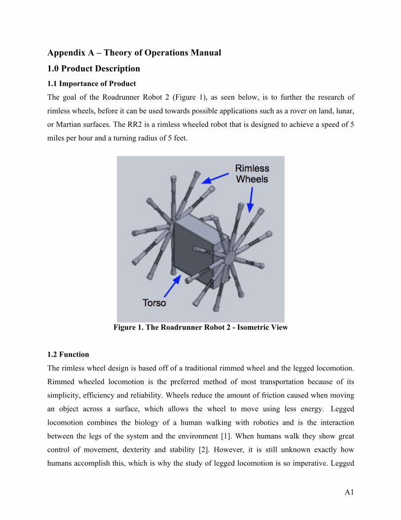
The goal of the Roadrunner Robot 2 (Figure 1), as seen below, is to further the research of
rimless wheels, before it can be used towards possible applications such as a rover on land, lunar,
or Martian surfaces. The RR2 is a rimless wheeled robot that is designed to achieve a speed of 5
miles per hour and a turning radius of 5 feet.
Figure 1. The Roadrunner Robot 2 - Isometric View
1.2 Function
The rimless wheel design is based off of a traditional rimmed wheel and the legged locomotion.
Rimmed wheeled locomotion is the preferred method of most transportation because of its
simplicity, efficiency and reliability. Wheels reduce the amount of friction caused when moving
an object across a surface, which allows the wheel to move using less energy. Legged
locomotion combines the biology of a human walking with robotics and is the interaction
between the legs of the system and the environment [1]. When humans walk they show great
control of movement, dexterity and stability [2]. However, it is still unknown exactly how
humans accomplish this, which is why the study of legged locomotion is so imperative. Legged

A2
locomotion is used for movement over rough or uneven terrain, which is quite difficult for
traditional rigid robots. The rimless, spoked wheel combines the speed of a traditional rimmed
wheel with the mobility of legged locomotion. The rimless wheel has a hub, which is surrounded
by spokes with a fixed angle between them. By being able to control the dynamic motion of the
robot, this could lead to a significant decrease in the energy required by the system, which would
increase the rimless wheel’s efficiency [3].
1.3 Functional and Physical Specifications
The RR2 is able achieve a speed of 5 miles per hour and a turning radius of 5 feet and can be
controlled by using the remote control up to a distance of 50 feet. The remote control has
sufficient capabilities to stop the motor, increase motor speed, decrease motor speed, and control
turning operations. The microcontroller will receive commands from the robot operator through
Zigbee Mesh network, which uses IEEE standard 802.15.4. It will output speed and control
commands to the motors through the ESC (electronic speed controller). The robot does not
exceed 20 pounds, the radius of the wheel is 10” and the width is 1 foot.
2.0 Theory of Operation
2.1 Mechanical
The Lithium polymer batteries contain potential energy that is used to power the motors. The
motors transfer the Potential energy into kinetic energy and turn a shaft. The shaft spins the
drivetrain, hubs and legs to allow the RR2 to move. The motion of the RR2 will depend on
which direction each motor is spun and at what rate it is spun. As each leg makes contact with
the ground, some of that energy is lost which decreases the amount of possible motion. Each leg
of the Road Runner Robot 2 will be assembled with a spring attached to the lower half of each
leg. With the addition of a spring, some of energy that was previously lost will be stored in the
form of potential energy as the weight of the robot compresses the spring. As the leg is rotated
and the spring begins to decompress, the energy will be released as kinetic energy and push the
robot forward. This design will increase the energy efficiency of the robot.

A3
Figure 2. Mass Spring Free Body Diagram [6]
Figure 3. Rimless Wheel Free Body Diagram
2.2 Electronics
2.2.1 Introduction
The RR2 is driven by two Kinexsis 4000 Kv brushless motors. Each motor is controlled by a
Kinexsis electronic speed controller (ESC), which receives input from the Arduino Mega
through the PWM pins. The ESCs use battery eliminator circuits (BECs) to supply the motors
power up to 6V at a current of 3A. Figure 4, illustrates the configuration of all electronic
components. Each component will be discussed in the following sections.

A4
Figure 4. Circuit Diagram of Electrical System
2.2.2 Motors
Two Kinexsis 1/10 scale 4000 Kv motors, as shown in Figure 5, below, will drive the robot.
Figure 6 shows the drive shaft and is what will transfer power from the motor through the gears
to the rimless wheels.
Figure 5. Kinexis 4000 Kv Motor [7]

A5
Figure 6. Motor Drive Shaft [7]
On the opposite side of the motor there are three connecting wires to connect the motor to the
corresponding ESCs. Figure 7 shows wires A, B, and C, which will connect to ports A, B, and C
on the ESCs.
Figure 7. Motor Connecting Wires [7]
2.2.3 Electronic Speed Controllers (ESCs)
The power provided to the motors will be controlled by the electronic speed controllers (ESCs).
The Motors and ESCs will use up to 11.1 volts and it will be supplied to the ESCs by two
separate 3s LiPo batteries. Figure 8 below shows an ESC. The ESCs vary the power to the motor
by varying the switching rate of a network of field effect transistors, or FETs. An Arduino Mega

A6
will be used to send the user’s controls to the ESCs and in turn the motors. On each ESC the
three wires color-coded blue, yellow, and orange are wires A, B, and C that connect the motors
to the ESCs. On the same side there is a red and black wire, which will connect to the Arduino
board via a PWM pin to send commands to the ESCs. On the opposite side there are two wires, a
red and a black, which will connect to a 3s LiPo battery’s positive and negative connection
terminals.
Figure 8. Kinexis Motor and ESC [8]
2.2.4 Arduino Mega 2560
The Arduino is a microcontroller that has 54 Digital I/O Pins, which 14 of can be used as PWM
outputs, as shown below in Figure 9. The Arduino Mega is used in the RR2 to provide input
from the remote control to the motors to either increase, decrease speed or have a speed of 0
mph. The ESC is connected to the Arduino Mega through the PWM pins. The Xbee shield is
connected to the Analog (A0-A5) and the Digital (0-7) on the Arduino. A 9V battery will power
the Arduino, since the recommended input voltage is 7-12 V. It has a USB connection, which
allows the program to be downloaded from the computer to the Arduino.

A7
Figure 9. Arduino Mega 2560 Pin Out [8]
2.2.5 Xbee Shield and Xbee Wireless Transmitter
The Xbee Shield mates with the Arduino Mega and extend the capabilities of the
microcontroller, which allows the Xbee wireless transmitter to transmit data to the Arduino. The
model of the Xbee wireless transmitter is the Xbee 1mW Trace Antenna - Series 1 mates to the
Xbee shield as seen in Figure 10.
Figure 10. Xbee Shield Mated with Xbee Wireless Transmitter [11]
The Xbee wireless transmitter can transmit data up to 100 feet indoors and operates within the
ISM 2.4 GHz frequency. [9]. The Xbee components are capable of transmitting data to another
Xbee
Shield
Xbee
transmitter

A8
Xbee and receiving data from one as well. The Xbee component a falls under the IEEE 802.15.4
which is a standard for low-rate wireless personal area networks and end device connectivity
which includes the Zigbee network that the Xbee uses [10]. The minimum pin connections are
shown below. Pin 1 is VCC; with a power supply of 3.3 V. Pin 10 is GND, which is the ground.
Pin 3 is DIN, which is data in when that blinks it means that data is being transmitted. Pin 2 is
DOUT, which is the data that is being received from another Xbee.
Figure 11. Pin Out of Xbee Transmitter [9]
2.2.6 Remote Control
The remote control is a wireless gamepad that is based on Arduino. The remote control has an
Arduino Leonardo, which the Xbee module is connected to, as shown in the figure below. The
Arduino Leonardo acts as a boot loader and holds the data and software for the Xbee. The remote
control has 2 joysticks, one reset button and 16 programmable buttons. The button controls are
discussed in the Operation Manual. It needs an input voltage of 7-12V and is powered by 3
“AAA” batteries.
Figure 12. Pin Out for Remote Control [12]

A9
2.3 Data Acquisition
There will be two different types of sensors used for data collection on the RR2. First is the IMU
or Inertial Measurement Unit, which calculates orientation, position and velocity. This will be
connected to the following pins on the Arduino Pro VCC to 3.3V, ground, SDA and SCL for
data transmission. The second are the encoders that will be attached on each axis to measure the
speed of the wheels and was requested by the customer. These encoders will each be connected
to ground and the Digital PWM pins on the Arduino Pro. The Arduino Pro will be connected to a
battery of 5V. The Arduino Pro will in turn be connected to the data logger, which will output
the data to an SD card.
2.4 Software Diagram
The program that the robot will be operated by will be as shown, in the software diagram
below. The robot will not move until a command is executed on the remote control. If the
command is not received the robot will not move and the user will select a command again. Once
the robot receives the command, it is to move forward until an obstacle is returned or needs to
turn. The remote control commands are discussed in the Operating Instructions.

A10
Figure 13. Software Diagram
3.0 Operating and Setup Instructions
Important Note: The legs of the RR2 can navigate most floors. However, we strongly
recommend you use the RR2 in indoors only. Never use RR2 near stairs. Do not use near water.
Setup Instructions
1. Place the RR2 on the floor in an indoor environment
2. Make sure two legs for each wheel are touching the ground (one leg is obstructed by the
box) and the robot is in standstill position, as shown below.

A11
Figure 14. RR2 Standstill Position
Powering Up RR2
1. Slide the lid out of the container.
2. Remove lid from RR2
Figure 15. Lid Removal

A12
1. Make sure one battery labeled as “3S” is connected to each ESC.
Figure 16. Battery Connected to ESC Wires [13]
2. Push switch UP into the on position for each ESC.
Figure 17. Switch connected to ESC in OFF Position[14]
3. Make sure the 9V battery is connected to the Arduino. The orange LED should flash on
and off when the board is receiving power, as shown circled below.

A13
Figure 18. Showing ON LED on Arduino Mega
4. Slide the lid back onto robot, as shown in Figure 19.
Figure 19. Sliding Lid
5. RR2 is on and ready for use. Once the robot is powered up, the robot is always on until
you power off and disconnect the robot.

A14
Powering off
6. Slide the lid off the box, as shown in Figure 15 in the powering on instructions.
7. Push switch for both ESC’s into the down position, as shown in Figure 17.
8. Unplug the “3S” batteries from each ESC.
9. Unplug the 9V battery for the Arduino
10. Make sure no lights are blinking in the box. If so return to steps 2-4.
11. Slide the lid back on the box, as shown in step Figure 19.
Remote Control Usage
1. Flip the switch located on the back of the remote to power up the remote
Figure 20. Remote Control Power Switch
2. The “Mode” light on the remote will light up so you know the remote is turned on.

A15
Figure 21. Showing the Mode light on Remote Control
Powering Remote Control Off
1. Push the power button to the right in the off position
2. Make sure the “Mode” light is not lit up on the remote to make sure that it is turned off.
Remote Control Commands
Figure 22. Remote Control Commands

A16
Section 4.0 Troubleshooting Instructions
Table 1 contains the most common issues that may occur while using the RR2 and ways to fix
those issues.
Table 1. Issues and Mitigation
Issue Mitigation
When ON button is pressed on remote control nothing happens
• Make sure that there is power going to Arduino and Remote control
• Be sure all batteries are charged • Be sure all wires are connected • Check the Zigbee in the remote control to
ensure all connections are secure
Data is not being collected from OpenLog or wheel encoder
• Check wires connecting the Open log to the Arduino
• Check for power to Arduino • These LEDs can be very useful for debugging.
Wheel doesn’t move when forward movement is inputted
• Turn robot off and then back on • Check motors power to ensure a good
connection • Check batteries are charged • Check for loose wiring
Loss of wireless control of robot • Ensure range of wireless transmitter is not exceeded.
• May be due to interferences- try operating in a different location.
Leg falls off while operating • Inspect for any damages to leg • Do not re-attach if damaged • Re-attach leg and ensure the fastener is
tightened if leg is undamaged

A17
References [1] Xiao, John, Siegwart, and Nourbakhsh. Robot Locomotion and Kinematics. Rep. N.p.: n.p., 2005. Print. [2] Surya Nurzaman. "Bio-Inspired Motor Control." Lecture 2: Legged Locomotion. ETH Zurich, 25 Sept. 2012. Web. [3] Coleman, Michael J. "Dynamics And Stability Of A Rimless Spoked Wheel: A Simple 2D System With Impacts." Dynamical Systems: An International Journal 25.2 (2010): 215-238. Computer Source. Web. [4] "IEEE 802.15 WPAN™ Task Group 4 (TG4)." IEEE 802.15.4. IEEE, n.d. Web. 20 Sept.
2016.
[5] Hugh, Jack “Dynamic System Modeling and Contols” reative Commons Attribution-Noncommercial-Share Alike 3.0 United States License. Web [6] "Kinexsis 1/10 4-pole Brushless Motor 4000kv R/c Buggy Truck Kxss1002."Terapeak. N.p., n.d. Web. 20 Sept. 2016. [7] "1/10 4-Pole 4000Kv ESC/Motor Combo | HorizonHobby." 1/10 4-Pole 4000Kv ESC/Motor
Combo | HorizonHobby. N.p., n.d. Web. 20 Sept. 2016. [8] "Arduino Circuit Schematics Using Eagle CAD Software." Merry Music. N.p., n.d. Web. 20
Sept. 2016.
[9] "XBEE Module Manual." SparkFun. SparkFun, n.d. Web.
[11] "Arduino XBee Shield." Liquidware :. N.p., n.d. Web. 20 Sept. 2016.
[12] "Www.robotshop.com." N.p., n.d. Web. 20 Sept. 2016.
[13] Brian Schneider / Brian Is the Manager, Webmaster, & Social Media Guru for Roger's
Hobby Center. He's Been in the Hobby Industry over a Decade, Teaching People the Essentials
of the R/C World. He's Written a Number of Helpful Guides, including A Guide to LiPo
Batteries. "Dynamite Tazer Programming Guide." Roger's Hobby Center. N.p., n.d. Web. 20
Sept. 2016.

B1
Appendix B – Test Plan
1.0 Introduction
The purpose of this test plan is to demonstrate the locomotion of a rimless wheeled robot.
Evaluating the RR2 will focus on speed and turning abilities, however other testing procedures
will be conducted to verify that the robot performs according to the specifications stated in
Appendix A.
2.0 Scope
Included in this plan are the testing procedures, facilities, and materials necessary to evaluate the
RR2.
3.0 Features To Be Tested
The main areas of focus for testing on the RR2 are going to be its performance specifications.
Although there will be other tests conducted, the specifications of turning radius and speed will
be the team's main concern. Other specifications that will be tested include but are not limited to;
weight, dimensions, power supply, electronics configuration, and the controls.

B2
Table 1. Compliance Matrix
Item
Number Feature Tested Specification
Testing
Procedure Compliance Status
(Pass/Fail)
1 Dimensions, radius,
width
1.2.1 1.2.1.1 1.2.1.2
Test T-1
2 Weight 1.2.2 Test T-2
3 Number of legs 1.2.3 Visual
4 Material 1.2.4 Visual
5 Soldering 1.2.5 Visual
6 Speed 2.1 2.7
Test T-3
7 Microcontroller 2.2 Visual
8 Microcontroller 2.2.1 Test T-4
9 Microcontroller 2.2.2 Test T-5
10 Remote Control 2.3 Test T-6
11 Power Supply 2.4 Visual
12 Spring 2.5 Visual
13 Turn Radius 2.6 Test T-7
4.0 Test Facility
Testing will be conducted inside the Main Building of the UTSA Main Campus. It is imperative
to test indoors in order to have a controlled environment and to avoid interference with the
microcontroller. The floor of the main building is 12” x 12” tile and they are grouted 8
millimeters. This allows for a smooth and nearly seamless test floor. The test facility will have to
be a minimum of 100 feet long in order to meet one of the test requirements. Painter’s tape, a
stopwatch and a measuring tape will all be required to set up the test facility.

B3
A computer is needed for the encoder, microcontroller, and to record data. The encoder and IMU
have an SD Card (Secure Digital Card) to store the collected data, which will be viewed on the
computer. Components of the microcontroller require coding on the Arduino software.
5.0 Testing
5.1 Visual Verification
Items listed in Table 1 as having a visual testing procedure require no equipment or data
analysis. A “pass” will be issued if the feature is existent on the robot.
5.2 Test Procedures
Test T-1
Method: Physical test.
Evaluated Specifications: 1.2.1
1.2.1.1
1.2.1.2
Purpose/Scope: The purpose of this test to verify that the dimensions of the RR2
meet the specifications.
Items Under Test: The whole robot and rimless wheel.
Precautions: Ensure that all electrical systems are powered off.
Special
Conditions/Limitations:
Test must be witnessed by all team members.
Equipment/Facilities: Tape measure.
Data Recording: Data will be recorded in Table 2.
Acceptance Criteria: The radius of the rimless wheel should not exceed 2 feet. The
width of the robot should not exceed 1.5 feet.

B4
Procedure: Using the tape measure, measure the radius of the rimless wheel
and the overall width of the robot.
Troubleshooting: None.
Post-Test Activities: None.
Table 2. Test T-1 Data
Dimension Measurement (ft)
Radius of rimless wheel
Width of robot
Pass/Fail
Test T-2
Method: Physical test.
Evaluated Specifications: 1.2.2
Purpose/Scope: The purpose of this test to verify that the weight of the RR2
meets the specifications.
Items Under Test: The whole robot, including all electrical components, which are
housed in the torso.
Precautions: Ensure that all electrical systems are powered off.
Special
Conditions/Limitations:
Test must be witnessed by all team members.
Equipment/Facilities: Weight Scale.
Data Recording: Data will be recorded in Table 3.

B5
Acceptance Criteria: The weight of the robot should not exceed 20 pounds.
Procedure: Place the RR2 on the scale and record the weight.
Troubleshooting: None.
Post-Test Activities: None.
Table 3. Test T-2 Data
Measurement (lbs)
Weight of RR2
Pass/Fail
Test T-3
Method: Mechanical test and analysis.
Evaluated
Specifications:
2.1
2.7
Purpose/Scope: The purpose of this test is to measure the speed of the RR2 and verify
that it meets the specifications.
Items Under Test: The entire robot and its components.
Precautions: Ensure the test area has enough space, is in a still position before
starting, and be gentle with the controls to avoid damage and injury.
Special
Conditions/Limitations:
Test must be witnessed by all team members. After each test run, the
encoder data will need to be collected from the microcontroller.
Equipment/Facilities: The RR2 will be tested indoors on flat tile without grout spacing. A
computer, data cord, tape measure, and tape are required.

B6
Data Recording: Data will be recorded in Table 4. An encoder will be attached to the
axle and record the number of revolutions over a period of time.
Using Equation 1, calculations will be made to convert the recorded
angular speed (rpm) into linear speed (mph).
Acceptance Criteria: The RR2 must travel at a speed of 5 mph for a distance of 100 feet.
Procedure: Using the tape measure and tape, mark the starting line and the finish
line 100 feet away. Place the RR2 at the start line. Make a test run
and start the stopwatch when the RR2 begins to move. Stop the
stopwatch when the RR2 reaches the finish line. Use the computer
and data cord to load the collected data from the encoder.
Troubleshooting: Verify correct wiring, make sure electrical components are not
overheating, and ensure the battery has enough power.
Post-Test Activities: After the final test run, all power need to be switched off, batteries
need to be unplugged, and all electronics inside the torso will need
time to cool to room temperature before transporting.
Table 4. Test T-3 Data
Test Run Measurement (mph)
Test Run 1
Test Run 2
Test Run 3
Test Run 4
Test Run 5
Pass/Fail

B7
Test T-4
Method: Electrical Test and Analysis
Evaluated
Specifications:
2.2.1
Purpose/Scope: The purpose of this test is to measure the flash memory on the
Arduino Mega to make sure it does not go above the maximum 256
KB.
Items Under Test: Arduino Mega 2560.
Precautions: Ensure that there is no water in the testing area.
Special
Conditions/Limitations:
Test must be witnessed by all team members.
Equipment/Facilities: Must be tested indoors with a computer with Arduino software, the
Arduino Mega 2560 and USB Cable type A/B.
Data Recording: Data will be recorded in Table 5.
Acceptance Criteria: The flash memory must not exceed 256 KB.
Procedure: Compile the program for the robot using the Arduino Software.
Check the bottom of the Arduino program window and it will show
“Binary Sketch Size”. Report this number in the table below.
Troubleshooting: Make sure electrical components are not overheating and check for
errors when compiling the program
Post-Test Activities: After the test the Arduino needs to be unplugged from the computer
and the battery disconnected from the Arduino.

B8
Table 5. Test T-4 Data
Pass/Fail
Test Run 1
Pass/Fail
Test T-5
Method: Electrical Test and Analysis
Evaluated
Specifications:
2.2.2
Purpose/Scope: The purpose of this test is to measure make sure the Arduino works
and the correct voltages are being applied to the various pins.
Items Under Test: 9 Battery.
Precautions: Ensure that there is no water in the testing area.
Special
Conditions/Limitations:
Test must be witnessed by all team members.
Equipment/Facilities: Digital Multimeter.
Data Recording: Data will be recorded in Table 6.
Acceptance Criteria: The voltage should be between 7V-12V
Procedure: Adjust the Digital Multimeter to DC Voltage. Connect the black
probe to the negative side of the battery and the red probe to the
positive side of the battery.
Troubleshooting: Make sure electrical components are not overheating.

B9
Post-Test Activities: Turn off all power.
Table 6. Test T-5 Data
Pass/Fail
Test Run 1
Pass/Fail
Test T-6
Method: Electrical test.
Evaluated
Specifications:
2.3
Purpose/Scope: The purpose of this test is verify that the remote control is able to
successfully communicate to the microcontroller.
Items Under Test: Remote control and RR2 including, but not limited to, Zigbee module
and motor.
Precautions: Ensure the test area has enough space, is in a still position before
starting, and be gentle with the controls to avoid damage and injury.
Special
Conditions/Limitations:
Test must be witnessed by all team members
Equipment/Facilities: The RR2 will be tested indoors on flat tile without grout spacing.
Tape measure and tape is required.
Data Recording: Data will be recorded in Table 5.
Acceptance Criteria: The remote control must successfully communicate with the RR2
from a distance of at least 50 feet.

B10
Procedure: Using the tape measure and tape, set the RR2 at a distance of 50 feet
from the remote control. First turn on the remote control and robot.
Press the appropriate buttons to perform the following movements:
stop, increase speed, decrease speed, and turn. This test will be
repeated for distances of 60 feet, 70 feet, 80 feet, 90 feet and 100 feet.
Troubleshooting: Verify correct wiring, make sure electrical components are not
overheating, and ensure the battery has enough power.
Post-Test Activities: After the final test, all power need to be switched off, batteries need
to be unplugged, and all electronics inside the torso will need time to
cool to room temperature before transporting.
Table 7. Test T-6 Data
Movement Pass/Fail
Stop
Increase Speed
Decrease Speed
Turn
Pass/Fail
Test T-7
Method: Mechanical test and analysis.
Evaluated Specifications: 2.6
Purpose/Scope: The purpose of this test is to measure the turning radius of the RR2
and verify that it meets the specifications.

B11
Items Under Test: The entire robot and its components.
Precautions: Ensure the test area has enough space, is in a still position before
starting, and be gentle with the controls to avoid damage and injury.
Special
Conditions/Limitations:
Test must be witnessed by all team members.
Equipment/Facilities: The robot will be tested indoors on flat tile without grout spacing.
Tape measure and tape are required.
Data Recording: Data will be recorded in Table 6.
Acceptance Criteria: The RR2 must make a complete turn within the 5 foot radius circle.
Procedure: Using the tape measure and tape, mark a five foot circle on the floor.
Position the outer edge of the robot on the tape line. Run the robot to
make a turn.
Troubleshooting: Verify correct wiring, make sure electrical components are not
overheating, and ensure the battery has enough power.
Post-Test Activities: After the final test, all power need to be switched off, batteries need
to be unplugged, and all electronics inside the torso will need time
to cool to room temperature before transporting.
Table 8. Test T-7 Data
Movement Pass/Fail
Test Run 1
Test Run 2
Test Run 3
Pass/Fail

B12
6.0 Data Analysis
6.1 Speed
The ratio of distance over time will calculate the speed of the robot. The speed will also be
calculated by the encoder inside the robot. The encoder will consist of a sensor and a gear. The
sensor detects the gear teeth and reports it as changes in voltage. The changes of voltage are
graphed as a function of time. With the graph you can use the equation below to calculate speed.
Equation 1. Speed
2�(# �� ������)(������ �� �����)
(����� # �� ����ℎ)(���� �� ℎ����)= ���
6.2 Turning Radius
The turning radius is the smallest circular turn one is able to achieve, measured from the origin
of the circle to the outer edge of the RR2. To calculate turn radius, the vehicle would start a
defined position and would turn one direction as much as it could. The vehicle would turn in a
circle and come back to the spot it started. If you track the measure the radius of the vehicle’s
path, this will be the turning radius.
Figure 1. Turning Radius
6.3 Voltage Test
The voltage drop among each component can be calculated by analyzing the closed loops on the
circuit schematic. Each electrical component has a specified voltage requirement. Measured
values of the voltage drop on each component will be recorded and compared to the components
specifications.

B13
7.0 Schedule
A detailed timeline for the testing period is included below in Figure 2. Testing will conclude on
November 4, 2016. The breakdown of the testing process is as follows:
1. Test Plan (34 days)
2. Fabrication and assembly (32 days)
3. Testing (12 days)
4. Data analysis and reporting (12 days)
Figure 2. Gantt Chart
8.0 Program Risks and Mitigation
There are two risks to consider in the fabrication process and one risk in performance. The first
risk is the possibility of acquiring materials late. This can be remedied by starting assembly on
available parts and testing on individual components during this idle time. The second risk is the
possibility of the 3D printed parts not printing correctly. It is recommended to print a single part
to check for accuracy before printing multiple duplicate parts. The last risk is associated with the

B14
remote control not communicating properly with the microcontroller. To avoid damaging the
robot or personal injury, it is encouraged to ensure the performance of these components before
assembling them to the RR2.
9.0 Communications
Communications on testing progress and all aspects of the project are available during bi-weekly
meetings. The primary contact for ABC Ngineering is Aspen Meineke, Project Manager (210-
954-4723)

C1
Appendix C – Test Report
1.0 Introduction
The purpose of this test plan is to demonstrate the locomotion of a rimless wheeled robot.
Evaluating the RR2 will focus on speed and turning abilities, however other testing procedures
will be conducted to verify that the robot performs according to the specifications stated in
Appendix A.
2.0 Scope
Included in this plan are the testing procedures, facilities, and materials necessary to evaluate the
RR2.
3.0 Features To Be Tested
The main areas of focus for testing on the RR2 are going to be its performance specifications.
Although there will be other tests conducted, the specifications of turning radius and speed will
be the team's main concern. Other specifications that will be tested include but are not limited to;
weight, dimensions, power supply, electronics configuration, and the controls.

C2
Table 1. Compliance Matrix
Item
Number Feature Tested Specification
Testing
Procedure Compliance Status
(Pass/Fail)
1 Dimensions, radius,
width
1.2.1 1.2.1.1 1.2.1.2
Test T-1 Pass
2 Weight 1.2.2 Test T-2 Pass
3 Number of legs 1.2.3 Visual Pass
4 Material 1.2.4 Visual Pass
5 Soldering 1.2.5 Visual Pass
6 Speed 2.1 2.7
Test T-3 Pass
7 Microcontroller 2.2 Visual Pass
8 Microcontroller 2.2.1 Test T-4 Pass
9 Microcontroller 2.2.2 Test T-5 Pass
10 Remote Control 2.3 Test T-6 Pass
11 Power Supply 2.4 Visual Pass
12 Spring 2.5 Visual Pass
13 Turn Radius 2.6 Test T-7 Pass

C3
Table 2. Test Matrix
Test Type Description
T-1 Quality Verify the dimensions of the RR2
T-2 Quality Verify the weight of the RR2
T-3 Performance Measure speed of the RR2 when going straight
T-4 Performance Measure the flash memory of the microcontroller
T-5 Performance,
Quality Measure the power limitations of the microcontroller
T-6 Performance,
Safety Verify that the remote control is able to stop, increase speed, decrease speed, and turn the RR2
T-7 Performance Measure the turning radius
4.0 Test Facility
Testing will be conducted inside the Main Building of the UTSA Main Campus. It is imperative
to test indoors in order to have a controlled environment and to avoid interference with the
microcontroller. The floor of the main building is 12” x 12” tile and they are grouted 8
millimeters. This allows for a smooth and nearly seamless test floor. The test facility will have to
be a minimum of 100 feet long in order to meet one of the test requirements. Painters tape, a
stopwatch and a measuring tape will all be required to set up the test facility.
A computer is needed for the encoder, microcontroller, and to record data. The encoder and IMU
have an SD Card (Secure Digital Card) to store the collected data, which will be viewed on the
computer. Components of the microcontroller require coding on the Arduino software.
5.0 Testing
5.1 Visual Verification
Items listed in Table 1 as having a visual testing procedure require no equipment or data
analysis. A “pass” will be issued if the feature is existent on the robot.

C4
5.2 Test Procedures
Test T-1
Method: Physical test.
Evaluated Specifications: 1.2.1
1.2.1.1
1.2.1.2
Purpose/Scope: The purpose of this test to verify that the dimensions of the RR2
meet the specifications.
Items Under Test: The whole robot and rimless wheel.
Precautions: Ensure that all electrical systems are powered off.
Special
Conditions/Limitations:
Test must be witnessed by all team members.
Equipment/Facilities: Tape measure.
Data Recording: Data will be recorded in Table 2.
Acceptance Criteria: The radius of the rimless wheel should not exceed 2 feet. The
width of the robot should not exceed 1.5 feet.
Procedure: Using the tape measure, measure the radius of the rimless wheel
and the overall width of the robot.
Troubleshooting: None.
Post-Test Activities: None.

C5
Test T-2
Method: Physical test.
Evaluated Specifications: 1.2.2
Purpose/Scope: The purpose of this test to verify that the weight of the RR2 meets
the specifications.
Items Under Test: The whole robot, including all electrical components, which are
housed in the torso.
Precautions: Ensure that all electrical systems are powered off.
Special
Conditions/Limitations:
Test must be witnessed by all team members.
Equipment/Facilities: Weight Scale.
Data Recording: Data will be recorded in Table 3.
Acceptance Criteria: The weight of the robot should not exceed 20 pounds.
Procedure: Place the RR2 on the scale and record the weight.
Troubleshooting: None.
Post-Test Activities: None.
Test T-3
Method: Mechanical test and analysis.
Evaluated Specifications: 2.1
2.7
Purpose/Scope: The purpose of this test is to measure the speed of the RR2 and

C6
verify that it meets the specifications.
Items Under Test: The entire robot and its components.
Precautions: Ensure the test area has enough space, is in a still position before
starting, and be gentle with the controls to avoid damage and injury.
Special
Conditions/Limitations:
Test must be witnessed by all team members. After each test run, the
encoder data will need to be collected from the microcontroller.
Equipment/Facilities: The RR2 will be tested indoors on flat tile without grout spacing. A
computer, data cord, tape measure, and tape are required.
Data Recording: Data will be recorded in Table 4. An encoder will be attached to the
axle and record the number of revolutions over a period of time.
Using Equation 1, calculations will be made to convert the recorded
angular speed (rpm) into linear speed (mph).
Acceptance Criteria: The RR2 must travel at a speed of 5 mph for a distance of 100 feet.
Procedure: Using the tape measure and tape, mark the starting line and the finish
line 100 feet away. Place the RR2 at the start line. Make a test run
and start the stopwatch when the RR2 begins to move. Stop the
stopwatch when the RR2 reaches the finish line. Use the computer
and data cord to load the collected data from the encoder.
Troubleshooting: Verify correct wiring, make sure electrical components are not
overheating, and ensure the battery has enough power.
Post-Test Activities: After the final test run, all power need to be switched off, batteries
need to be unplugged, and all electronics inside the torso will need
time to cool to room temperature before transporting.
Test T-4
Method: Electrical Test and Analysis

C7
Evaluated Specifications: 2.2.1
Purpose/Scope: The purpose of this test is to measure the flash
memory on the Arduino Mega to make sure it does
not go above the maximum 256 KB.
Items Under Test: Arduino Mega 2560.
Precautions: Ensure that there is no water in the testing area.
Special
Conditions/Limitations:
Test must be witnessed by all team members.
Equipment/Facilities: Must be tested indoors with a computer with
Arduino software, the Arduino Mega 2560 and
USB Cable type A/B.
Data Recording: Data will be recorded in Table 5.
Acceptance Criteria: The flash memory must not exceed 256 KB.
Procedure: Compile the program for the robot using the
Arduino Software. Check the bottom of the
Arduino program window and it will show “Binary
Sketch Size”. Report this number in the table
below.
Troubleshooting: Make sure electrical components are not
overheating and check for errors when compiling
the program
Post-Test Activities: After the test the Arduino needs to be unplugged
from the computer and the battery disconnected
from the Arduino.

C8
Test T-5
Method: Electrical Test and Analysis
Evaluated
Specifications:
2.2.2
Purpose/Scope: The purpose of this test is to measure make sure the Arduino works
and the correct voltages are being applied to the various pins.
Items Under Test: 9 Battery.
Precautions: Ensure that there is no water in the testing area.
Special
Conditions/Limitations:
Test must be witnessed by all team members.
Equipment/Facilities: Digital Multimeter.
Data Recording: Data will be recorded in Table 6.
Acceptance Criteria: The voltage should be between 7V-12V
Procedure: Adjust the Digital Multimeter to DC Voltage. Connect the black
probe to the negative side of the battery and the red probe to the
positive side of the battery.
Troubleshooting: Make sure electrical components are not overheating.
Post-Test Activities: Turn off all power.
Test T-6
Method: Electrical test.
Evaluated
Specifications:
2.3

C9
Purpose/Scope: The purpose of this test is verify that the remote control is able to
successfully communicate to the microcontroller.
Items Under Test: Remote control and RR2 including, but not limited to, Zigbee module
and motor.
Precautions: Ensure the test area has enough space, is in a still position before
starting, and be gentle with the controls to avoid damage and injury.
Special
Conditions/Limitations:
Test must be witnessed by all team members
Equipment/Facilities: The RR2 will be tested indoors on flat tile without grout spacing.
Tape measure and tape is required.
Data Recording: Data will be recorded in Table 5.
Acceptance Criteria: The remote control must successfully communicate with the RR2
from a distance of at least 50 feet.
Procedure: Using the tape measure and tape, set the RR2 at a distance of 50 feet
from the remote control. First turn on the remote control and robot.
Press the appropriate buttons to perform the following movements:
stop, increase speed, decrease speed, and turn. This test will be
repeated for distances of 60 feet, 70 feet, 80 feet, 90 feet and 100 feet.
Troubleshooting: Verify correct wiring, make sure electrical components are not
overheating, and ensure the battery has enough power.
Post-Test Activities: After the final test, all power need to be switched off, batteries need to
be unplugged, and all electronics inside the torso will need time to
cool to room temperature before transporting.

C10
Test T-7
Method: Mechanical test and analysis.
Evaluated Specifications: 2.6
Purpose/Scope: The purpose of this test is to measure the turning radius of the RR2
and verify that it meets the specifications.
Items Under Test: The entire robot and its components.
Precautions: Ensure the test area has enough space, is in a still position before
starting, and be gentle with the controls to avoid damage and injury.
Special
Conditions/Limitations:
Test must be witnessed by all team members.
Equipment/Facilities: The robot will be tested indoors on flat tile without grout spacing.
Tape measure and tape are required.
Data Recording: Data will be recorded in Table 6.
Acceptance Criteria: The RR2 must make a complete turn within the 5 foot radius circle.
Procedure: Using the tape measure and tape, mark a five foot circle on the floor.
Position the outer edge of the robot on the tape line. Run the robot to
make a turn.
Troubleshooting: Verify correct wiring, make sure electrical components are not
overheating, and ensure the battery has enough power.
Post-Test Activities: After the final test, all power need to be switched off, batteries need
to be unplugged, and all electronics inside the torso will need time
to cool to room temperature before transporting.

C11
6.0 Data Analysis
6.1 Speed
The ratio of distance over time will calculate the speed of the robot. The speed will also be
calculated by the encoder inside the robot. The encoder will consist of a sensor and a gear. The
sensor detects the gear teeth and reports it as changes in voltage. The changes of voltage are
graphed as a function of time. With the graph you can use the equation below to calculate speed.
Equation 1. Speed
2�(# �� ������)(������ �� �����)
(����� # �� ����ℎ)(���� �� ℎ����)= ���
6.2 Turning Radius
The turning radius is the smallest circular turn one is able to achieve, measured from the origin
of the circle to the outer edge of the RR2. To calculate turn radius, the vehicle would start a
defined position and would turn one direction as much as it could. The vehicle would turn in a
circle and come back to the spot it started. If you track the measure the radius of the vehicle’s
path, this will be the turning radius.
Figure 1. Turning Radius
6.3 Voltage Test
The voltage drop among each component can be calculated by analyzing the closed loops on the
circuit schematic. Each electrical component has a specified voltage requirement. Measured
values of the voltage drop on each component will be recorded and compared to the components
specifications.

C12
7.0 Results
Results are either pass or fail based on the acceptance criteria for each procedure.
Table 3. Test T-1 Data
Dimension Measurement
Radius of rimless wheel 10 in
Width of robot 1 ft, 0.5 in
Pass/Fail Pass
Table 4. Test T-2 Data
Measurement
Weight of RR2 13.2 lbs
Pass/Fail Pass
Table 5. Test T-3 Data
Test Run Measurement
Test Run 1 4.6 mph
Test Run 2 3.8 mph
Test Run 3 5.6 mph
Test Run 4 6.1 mph
Test Run 5 5.9 mph
Pass/Fail Pass
Table 6. Test T-4 Data
Memory
Test Run 1 9.7 kB
Pass/Fail Pass

C13
Table 7. Test T-5 Data
Measurement
Test Run 1 8.4 V
Pass/Fail Pass
Table 8. Test T-6 Data
Movement Pass/Fail
Stop Pass
Increase Speed Pass
Decrease Speed Pass
Turn Pass
Pass/Fail Pass
Table 9. Test T-7 Data
Movement Measurement
Test Run 1 1.6 ft
Test Run 2 2.3 ft
Test Run 3 2.1 ft
Pass/Fail Pass
8.0 Schedule
A timeline for the testing period is included below in Figure 2. The testing portion of this project
concluded on November 15, 2016.

C14
Figure 2. Gantt Chart
9.0 Conclusions and Recommendations
The Roadrunner Robot 2 passed all specifications. ABC Ngineering will keep working to
achieve more consistent results.
10.0 Communications
Communications on the testing program and all aspects of the project are available during bi-
weekly meetings. The primary contact for ABC Ngineering is Aspen Meineke, Project Manager
(210-954-4723).

D1
Appendix D – Design Drawings
Figure 1. Roadrunner Robot 2

D2
Figure 2. Body Subassembly

D3
Figure 3. Motor Subassembly

D4
Figure 4. Microcontroller Subassembly

D5
Figure 5. Rimless Wheel Subassembly

D6
Figure 6. Leg Subassembly

D7
Figure 7. Hub Subassembly

D8
Figure 8. Motor Shelf

D9
Figure 9. Box Back Wall

D10
Figure 10. Box Sides

D11
Figure 11. Lid

D12
Figure 12. Axle

D13
Figure 13. Leg Tube

D14
Figure 14. Leg Rod

D15
Figure 15. Hub

D16
Figure 16. Peg

E1
Appendix E - Calculations
Calculations
Equation 1. Concept 1 Turning Radius Calculations
Equation 2. Concept 2 Turning Radius Calculations

E2
Equation 3. Concept 3 Turning Radius Calculations
Equation 4. Speed Calculations
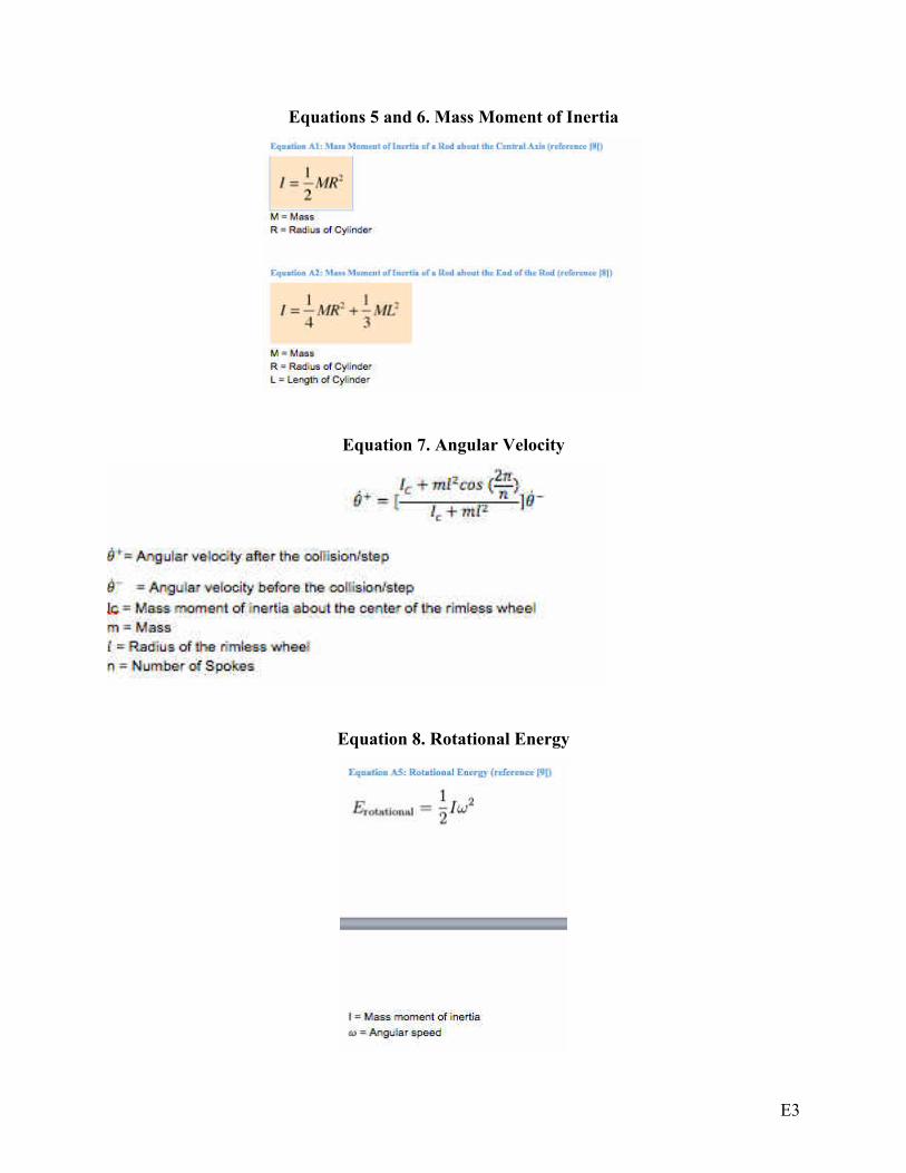
E3
Equations 5 and 6. Mass Moment of Inertia
Equation 7. Angular Velocity
Equation 8. Rotational Energy

E4
Equation 9. Estimated Battery Usage Calculations
Estimated Time = Battery Capacity (Ah) / Current Used (A)
Battery Capacity = 3000 mAh
Current Used 7A
Estimated Time = 3/7 (h) = approximately 25 minutes
Table 11. Moment of Inertia
Moment of Inertia(lbm*in^2)
Rod about central axis 0.028
Rod about its end 11.828
3 spokes per side 30.750
4 spokes per side 37.058
5 spokes per side 43.365
6 spokes per side 49.673
7 spokes per side 55.980
8 spokes per side 62.288
9 spokes per side 68.595
10 spokes per side 74.903
11 spokes per side 81.210
12 spokes per side 87.518
13 spokes per side 93.825
14 spokes per side 100.133
15 spokes per side 106.440
16 spokes per side 112.748
17 spokes per side 119.055
18 spokes per side 125.363
19 spokes per side 131.670
20 spokes per side 137.978

E5
Table 12. Angular Velocity
#
Spokes
Inital
Angular
Velocity
(rad/sec)
Mass
(lbm)
Radius
of Rim
(in)
Mass
Moment of
Inertia
About
Center of
Wheel
(lbm*in^2)
Final
Angular
Velocity
(rad/sec)
Inital
Energy
(in-lb)
Final
Energy
(in-lb)
Energy
Lost
(in-lb)
Percent of
Energy
Remaining
Percent Energy
Remaining/Mass
(1/lb)
3 7.333 0.9214 10 30.7500 -0.9142 2.1414 0.0333 2.1081 1.55% 0.0169
4 7.333 1.1104 10 37.0575 1.8349 2.5806 0.1616 2.4190 6.26% 0.0564
5 7.333 1.2994 10 43.3650 3.5339 3.0199 0.7013 2.3185 23.22% 0.1787
6 7.333 1.4884 10 49.6725 4.5839 3.4591 1.3517 2.1074 39.08% 0.2625
7 7.333 1.6774 10 55.9800 5.2629 3.8983 2.0080 1.8903 51.51% 0.3071
8 7.333 1.8664 10 62.2875 5.7226 4.3376 2.6417 1.6959 60.90% 0.3263
9 7.333 2.0554 10 68.5950 6.0467 4.7768 3.2480 1.5289 67.99% 0.3308
10 7.333 2.2444 10 74.9025 6.2830 5.2161 3.8292 1.3869 73.41% 0.3271
11 7.333 2.4334 10 81.2100 6.4602 5.6553 4.3892 1.2661 77.61% 0.3189
12 7.333 2.6224 10 87.5175 6.5964 6.0945 4.9316 1.1629 80.92% 0.3086
13 7.333 2.8114 10 93.8250 6.7032 6.5338 5.4597 1.0741 83.56% 0.2972
14 7.333 3.0004 10 100.1325 6.7885 6.9730 5.9760 0.9971 85.70% 0.2856
15 7.333 3.1894 10 106.4400 6.8577 7.4123 6.4825 0.9298 87.46% 0.2742
16 7.333 3.3784 10 112.7475 6.9145 7.8515 6.9809 0.8706 88.91% 0.2632
17 7.333 3.5674 10 119.0550 6.9617 8.2908 7.4725 0.8183 90.13% 0.2527
18 7.333 3.7564 10 125.3625 7.0014 8.7300 7.9584 0.7716 91.16% 0.2427
19 7.333 3.9454 10 131.6700 7.0351 9.1692 8.4394 0.7299 92.04% 0.2333
20 7.333 4.1344 10 137.9775 7.0639 9.6085 8.9162 0.6923 92.80% 0.2244

E6
Figure 20. Spoke Effectiveness
Project Cost Analysis
Equation 10. Schedule Variance
�� = ���� − ����
Where SV = Schedule Variance
BCWP = Budgeted Cost of Work Produced
BCWS = Budgeted Cost of Work Scheduled
Equation 11. Cost Variance
�� = ���� − ����
Where CV = Cost Variance
BCWP = Budgeted Cost of Work Produced
ACWP = Actual Cost of Work Produced

E7
Equation 12. Schedule Performance Index
��� =����
����
Where SPI = Schedule Performance Index
BCWP = Budgeted Cost of Work Produced
BCWS = Budgeted Cost of Work Scheduled
Equation 13. Cost Performance Index
��� =����
����
Where CPI = Cost Performance Index
BCWP = Budgeted Cost of Work Produced
ACWP = Actual Cost of Work Produced
Equation 14. Cost Schedule Index
��� = ��� ⋅ ���
Where CSI = Cost Schedule Index
SPI = Schedule Performance Index
CPI = Cost Performance Index