abb i-bus knx application unit logic abl/s 2.1 product … · 3.4.4 project selection menu ... the...
TRANSCRIPT
ABB i-bus® KNX Application Unit Logic ABL/S 2.1 Product Manual


ABL/S, Application Unit Logic
© 2010 ABB STOTZ-KONTAKT GmbH 1
ABB i-bus KNX
Contents Page
1 General 4
1.1 Product and functional overview...........................................................5
2 Device technology 6
2.1 Technical data.......................................................................................6 2.2 Circuit diagram......................................................................................7 2.3 Dimension drawing ...............................................................................8 2.4 Assembly and installation .....................................................................8
3 Commissioning 10
3.1 Overview.............................................................................................10 3.2 Import of the application program in the ETS3...................................11 3.3 Verifying the installation outside of the ETS3.....................................16 3.4 User interface......................................................................................17 3.4.1 ABB – Logic Time 254EA/2..............................................................17 3.4.2 Title bar ............................................................................................17 3.4.3 Menu bar ..........................................................................................17 3.4.4 Project selection menu.....................................................................18 3.4.4.1 Save...............................................................................................18 3.4.4.2 Print ...............................................................................................18 3.4.4.3 Print preview..................................................................................18 3.4.4.4 Page setup.....................................................................................18 3.4.4.5 Exit .................................................................................................18 3.4.5 Edit selection menu..........................................................................19 3.4.5.1 Undo ..............................................................................................19 3.4.5.2 Redo ..............................................................................................19 3.4.5.3 Copy ..............................................................................................20 3.4.5.4 Paste..............................................................................................20 3.4.5.5 Import from Logic Time 200EA/1.4 device ....................................21 3.4.5.6 Import from an older application program .....................................23 3.4.5.7 Import from Logic Time 254EA device ..........................................24 3.4.5.8 Initialization ....................................................................................25 3.4.6 View selection menu ........................................................................26 3.4.6.1 Grid ................................................................................................26 3.4.6.2 Goto worksheet..............................................................................27 3.4.6.3 Refresh ..........................................................................................27 3.4.6.4 Dock toolbox ..................................................................................28 3.4.7 Help selection menu.........................................................................28 3.4.7.1 Help index F1.................................................................................28 3.4.7.2 About .............................................................................................28 3.4.8 Toolbar .............................................................................................29 3.4.8.1 Save...............................................................................................29 3.4.8.2 Undo last action.............................................................................29 3.4.8.3 Redo last action.............................................................................29 3.4.8.4 Copy ..............................................................................................30 3.4.8.5 Paste..............................................................................................30 3.4.8.6 Delete the selected element or link ...............................................31 3.4.8.7 Delete all objects and links ............................................................31 3.4.8.8 Define toolbar pin on position ........................................................32 3.4.8.9 Display help themes ......................................................................32
ABL/S, Application Unit Logic
© 2010 ABB STOTZ-KONTAKT GmbH 2
ABB i-bus KNX
3.4.8.10 Exit .................................................................................................32 3.4.8.11 Hotkey selection ............................................................................33 3.4.9 Toolbar .............................................................................................34 3.4.9.1 Input...............................................................................................34 3.4.9.2 Output ............................................................................................35 3.4.9.3 AND gate .......................................................................................35 3.4.9.4 OR gate .........................................................................................35 3.4.9.5 One hot gate ..................................................................................35 3.4.9.6 Gate ...............................................................................................36 3.4.9.7 Bidirectional gate ...........................................................................36 3.4.9.8 Timer..............................................................................................36 3.4.9.9 Staircase light ................................................................................36 3.4.9.10 Comparator....................................................................................37 3.4.9.11 Worksheet......................................................................................37 3.5 Working in the worksheet ...................................................................38 3.5.1 Assigning new elements ..................................................................38 3.5.2 Copying of elements ........................................................................39 3.5.3 Pasting of elements..........................................................................39 3.5.4 Selection of elements.......................................................................40 3.5.5 Multiple selection of elements ..........................................................40 3.5.6 Moving elements in the worksheet...................................................41 3.5.7 Linking functions ..............................................................................42 3.5.8 Deleting links ....................................................................................43 3.5.9 Displaying links.................................................................................44 3.6 Functions ............................................................................................45 3.6.1 Inputs and outputs............................................................................45 3.6.1.1 Input...............................................................................................45 3.6.1.2 Output ............................................................................................52 3.6.1.3 Edit communication object.............................................................57 3.6.1.4 Link with group addresses.............................................................61 3.6.2 AND gate..........................................................................................63 3.6.2.1 Creating and deleting inputs..........................................................65 3.6.3 OR gate ............................................................................................68 3.6.3.1 Creating and deleting inputs..........................................................70 3.6.4 One hot gate.....................................................................................73 3.6.4.1 Creating and deleting inputs..........................................................75 3.6.5 Unidirectional gate ...........................................................................78 3.6.6 Bidirectional Gate.............................................................................82 3.6.7 Timer ................................................................................................84 3.6.8 Staircaselight....................................................................................96 3.6.9 Comparator ....................................................................................100 3.6.10 Worksheet ......................................................................................106 3.7 Communication object ......................................................................108 3.7.1 Input ...............................................................................................108 3.7.2 Output.............................................................................................109 3.7.3 Input and output .............................................................................110
4 Planning and application 111
4.1 Help...................................................................................................111 4.2 Transient intermediate states (Glitches)...........................................112 4.2.1 Criteria for the occurrence of glitches ............................................113 4.2.2 Criteria for the non-occurrence of glitches .....................................114 4.3 Reaction time....................................................................................115 4.4 Reaction on bus voltage failure ........................................................115 4.5 Behaviour after voltage recovery......................................................116 4.5.1 Cold start ........................................................................................116 4.5.2 Warm start and bus reset...............................................................116
ABL/S, Application Unit Logic
© 2010 ABB STOTZ-KONTAKT GmbH 3
ABB i-bus KNX
Appendix VII
A.1 Scope of delivery ............................................................................... VII A.2 Directory of drawings ........................................................................ VIII A.3 Directory of tables................................................................................ X A.4 Index ................................................................................................... XI A.5 Ordering information .......................................................................... XII A.6 Notes................................................................................................. XIII

General
© 2010 ABB STOTZ-KONTAKT GmbH 4
ABB i-bus KNX
1 General
In modern buildings with ABB i-bus® KNX, logical and complex operations are becoming increasingly important, e.g. logic gates, gates, timing modules and comparators, which are required in the building system technology, can be defined and logically linked to each other.
With these basic elements, it is possible to implement logic control, logic operations, interlocks, fault signals, telegram multiplication and a range of further functions which are required in daily practice. Further applications, e.g. memory or sequence control can also be implemented using a combination of logical elements.
Working with logic functions differs in several points from working with a programmable logic controller (PLC) or a hard-wired programmed controller.
The applications described beforehand can be parameterised using the Application Unit Logic.
This manual provides you with detailed technical information relating to the Application Unit Logic, installation, programming and explains the Application Unit Logic using examples.
This manual is divided into the following sections:
Chapter 1 General
Chapter 2 Device technology
Chapter 3 Commissioning
Chapter 4 Planning and application
Appendix

General
© 2010 ABB STOTZ-KONTAKT GmbH 5
ABB i-bus KNX
1.1 Product and functional overview
The Application Unit Logic ABL/S 2.1 is a rail mounted device for insertion in the distribution board. The connection to the bus is implemented via a bus connection terminal on the front of the device. The assignment of the physical address as well as the parameter settings is carried out with ETS3 from version V1.0 onwards.
The device is powered via the ABB i-bus® and does not require an additional power supply.
The processing is implemented in the application program Logic Time 254 EA/2.
The device features comprehensive and clearly arranged functionality and permits usage in the most differing fields of application. The following list provides and overview:
254 inputs and outputs
50 logical functions
o AND
o OR
o One hot)
50 unidirectional and bidirectional gates
30 timers with
o ON delay
o OFF delay
o Pulse duration
o Staircase lighting function
10 comparators
200 worksheets
250 flags
Device technology
© 2010 ABB STOTZ-KONTAKT GmbH 6
ABB i-bus KNX
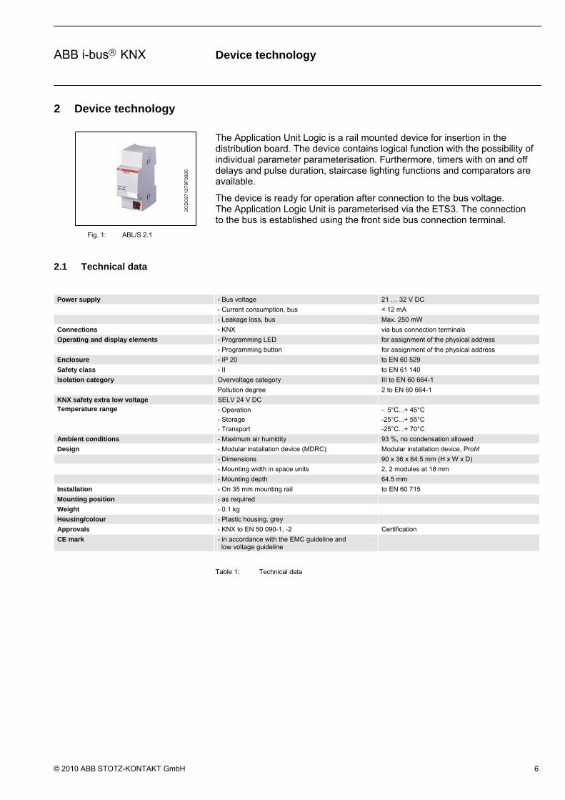
2 Device technology
The Application Unit Logic is a rail mounted device for insertion in the distribution board. The device contains logical function with the possibility of individual parameter parameterisation. Furthermore, timers with on and off delays and pulse duration, staircase lighting functions and comparators are available.
The device is ready for operation after connection to the bus voltage. The Application Logic Unit is parameterised via the ETS3. The connection to the bus is established using the front side bus connection terminal.
Fig. 1: ABL/S 2.1
2.1 Technical data
Power supply - Bus voltage 21 … 32 V DC
- Current consumption, bus < 12 mA
- Leakage loss, bus Max. 250 mW
Connections - KNX via bus connection terminals
Operating and display elements - Programming LED for assignment of the physical address
- Programming button for assignment of the physical address
Enclosure - IP 20 to EN 60 529
Safety class - II to EN 61 140
Isolation category Overvoltage category III to EN 60 664-1
Pollution degree 2 to EN 60 664-1
KNX safety extra low voltage SELV 24 V DC Temperature range - Operation
- Storage
- Transport
- 5°C...+ 45°C
-25°C...+ 55°C
-25°C...+ 70°C
Ambient conditions - Maximum air humidity 93 %, no condensation allowed
Design - Modular installation device (MDRC) Modular installation device, ProM
- Dimensions 90 x 36 x 64.5 mm (H x W x D)
- Mounting width in space units 2, 2 modules at 18 mm
- Mounting depth 64.5 mm
Installation - On 35 mm mounting rail to EN 60 715
Mounting position - as required
Weight - 0.1 kg
Housing/colour - Plastic housing, grey
Approvals - KNX to EN 50 090-1, -2 Certification
CE mark - in accordance with the EMC guideline and low voltage guideline
Table 1: Technical data
2
CD
C07
127
9F00
05

Device technology
© 2010 ABB STOTZ-KONTAKT GmbH 7
ABB i-bus KNX
Application program Max. number of
communication objects
Max. number of
group addresses
Max. number of
associations
Logic Time 254EA/2 254 254 254
Table 2: Application program
Note: ETS3 is required for programming. A “.VD3” type file must be imported. The application program is available in the ETS3 at ABB/controller/controller.
2.2 Circuit diagram
2CDC 072 053 F0005
Fig. 2: Circuit diagram
1 Label carrier
2 Programming button
3 Programming LED
4 Bus connection terminal
Device technology
© 2010 ABB STOTZ-KONTAKT GmbH 8
ABB i-bus KNX
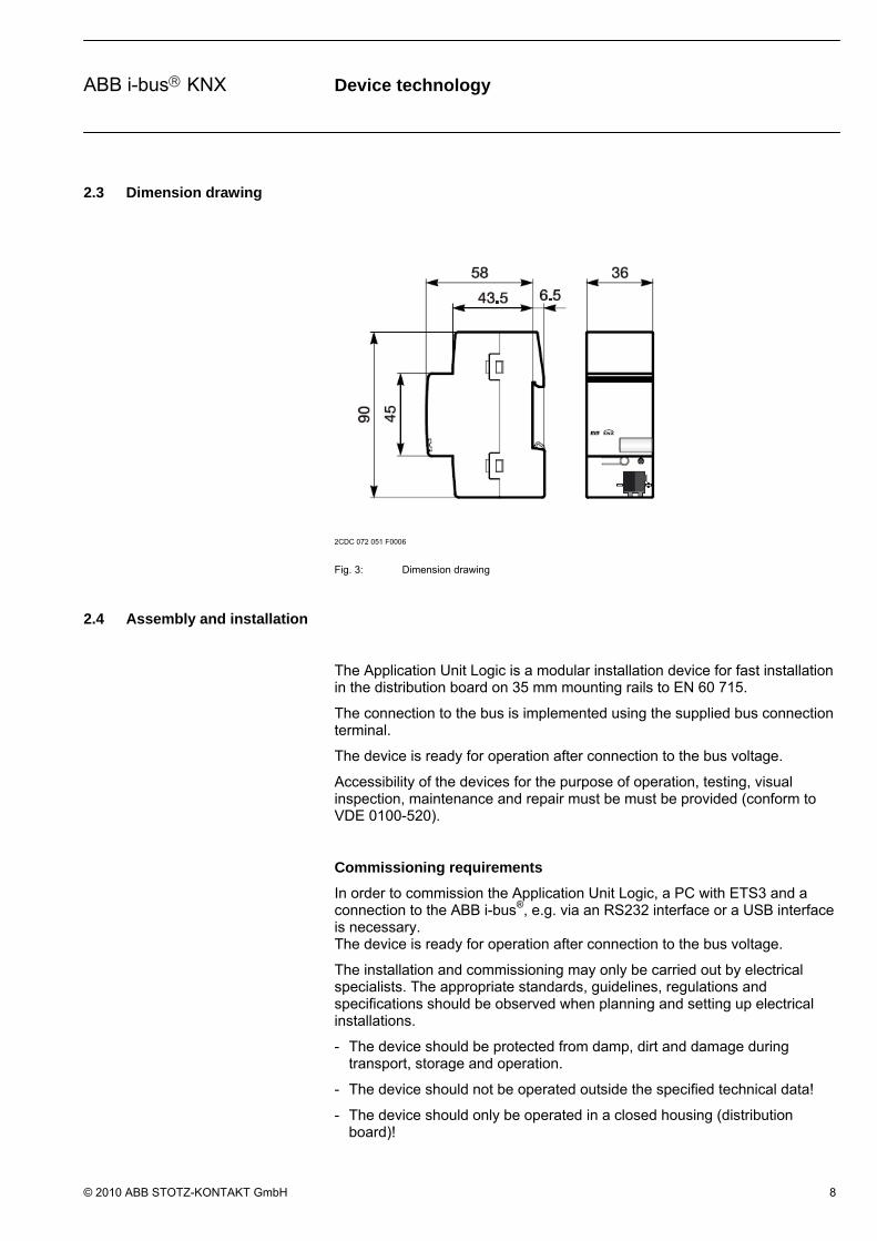
2.3 Dimension drawing
2CDC 072 051 F0006
Fig. 3: Dimension drawing
2.4 Assembly and installation
The Application Unit Logic is a modular installation device for fast installation in the distribution board on 35 mm mounting rails to EN 60 715.
The connection to the bus is implemented using the supplied bus connection terminal.
The device is ready for operation after connection to the bus voltage.
Accessibility of the devices for the purpose of operation, testing, visual inspection, maintenance and repair must be must be provided (conform to VDE 0100-520).
Commissioning requirements
In order to commission the Application Unit Logic, a PC with ETS3 and a connection to the ABB i-bus®, e.g. via an RS232 interface or a USB interface is necessary. The device is ready for operation after connection to the bus voltage.
The installation and commissioning may only be carried out by electrical specialists. The appropriate standards, guidelines, regulations and specifications should be observed when planning and setting up electrical installations.
- The device should be protected from damp, dirt and damage during transport, storage and operation.
- The device should not be operated outside the specified technical data!
- The device should only be operated in a closed housing (distribution board)!

Device technology
© 2010 ABB STOTZ-KONTAKT GmbH 9
ABB i-bus KNX
Supplied state
The Application Unit Logic is supplied with the physical address 15.15.255. The application program is pre-installed. Hence, only group addresses and parameters must be loaded during commissioning. The entire application can be reloaded if required. A longer downtime may result if the application program is changed or after a discharge.
Download behaviour
Due to the complexity of the device, the download bar can take up to 1.5 minutes to appear and will depend on the PC that is used.
Assignment of the physical address
The assignment and programming of the physical address is carried out in the ETS.
Cleaning
If devices become dirty, they can be cleaned using a dry cloth. Should a dry cloth not remove the dirt, they can be cleaned using a slightly damp cloth and soap solution. Corrosive materials or solutions should never be used.
Maintenance
The device is maintenance-free. No repairs should be carried out by unauthorised personnel if damage occurs (e.g. during transport or storage). The warranty expires if the device is opened.

Commissioning
© 2010 ABB STOTZ-KONTAKT GmbH 10
ABB i-bus KNX
3 Commissioning
3.1 Overview
For the Application Unit Logic, the application program “Logic Time 254 EA/2” is available. Programming requires ETS3. A maximum of 254 communication objects, 254 group addresses and 254 associations can be linked.
The following functions are available:
Inputs/outputs These correspond to the communication objects in the ETS3. A maximum of 254 are available.
Logical elements There are 50 AND, OR, one hot gates available.
Gates Can inhibit or enable the transfer of values. There are 50 unidirectional and bidirectional gates in total.
Timers For input / output delay and pulse duration. Also available are the staircase lighting elements. 30 in total are available.
Comparators Compares two input values with one another after an adjustable comparator operator. Up to 10 comparators can be used
Markers Markers are displayed where connection lines cross one another. A maximum of 250 are available.
Worksheets
The logic functions are engineered on the worksheets. A worksheet is a text field. It describes a part of the graphical parameterisation and is implemented in the form of jump labels. A maximum of 200 are available.
Table 3: Functions of the application program

Commissioning
© 2010 ABB STOTZ-KONTAKT GmbH 11
ABB i-bus KNX
3.2 Import of the application program in the ETS3
The Application Unit Logic is imported via the Import function into the ETS3. Thereafter the product database is automatically imported and the project data is updated.
Note: The application program for the Application Unit Logic is installed on the computer.
Add the Application Unit Logic in the ETS3 via the function Add device.
Thereafter, the dialog ABB Logic Time 254 EA Setup – Welcome to… becomes visible.
Fig. 4: Import of the application program Logic Time 254 EA Part 1
You access the following dialog via Next >. This accepts and acknowledges all instructions.
< Back
Is not active as there was not a previous installation page.
Next >
If you click on the Next > button, the next installation page is accessed. All of the information on the screen is acknowledged.
Cancel
If you click on the Cancel button, the installation process is ended.

Commissioning
© 2010 ABB STOTZ-KONTAKT GmbH 12
ABB i-bus KNX
Fig. 5: Import of the application program Logic Time 254 EA Part 2
In the User Information dialog, the general user information is requested.
Full Name
Enter the user name here.
Organization
Enter the organization/company name here.
Anyone who uses this computer
By choosing Anyone who uses this computer, all users of the computer are granted the right to use the application program.
Only for me (Full Name)
By choosing Only for me (Full Name), only the entered user on the PC is allowed to use the application program.
< Back
If you click on the <Back button, the next installation page is accessed.
Next >
If you click on the Next > button, the next installation page is accessed. All of the information on the screen is acknowledged.
Cancel
If you click on the Cancel button, the installation process is ended.
Commissioning
© 2010 ABB STOTZ-KONTAKT GmbH 13
ABB i-bus KNX
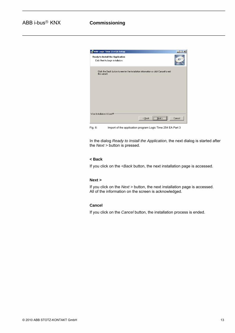
Fig. 6: Import of the application program Logic Time 254 EA Part 3
In the dialog Ready to Install the Application, the next dialog is started after the Next > button is pressed.
< Back
If you click on the <Back button, the next installation page is accessed.
Next >
If you click on the Next > button, the next installation page is accessed. All of the information on the screen is acknowledged.
Cancel
If you click on the Cancel button, the installation process is ended.

Commissioning
© 2010 ABB STOTZ-KONTAKT GmbH 14
ABB i-bus KNX
Fig. 7: Import of the application program Logic Time 254 EA Part 4
The application is installed in the Updating System dialog.
Cancel
If you click on the Cancel button, the installation process is ended.

Commissioning
© 2010 ABB STOTZ-KONTAKT GmbH 15
ABB i-bus KNX
Fig. 8: Import of the application program Logic Time 254 EA Part 5
The last dialog ABB Logic Time Plugin… confirms successful installation.
Finish
By pressing on the Finish button, the installation of the application program is ended and you return automatically to ETS3.
Commissioning
© 2010 ABB STOTZ-KONTAKT GmbH 16
ABB i-bus KNX
3.3 Verifying the installation outside of the ETS3
ABB_LT02
In the directory C:\Program Files\Common Files\EIBA sc\Baggage\2\ the ABB_LT02 folder must exist.
Note: If the ABB_LTO2 folder is deleted for some reason, it is automatically reinstalled the next time the product is accessed in the ETS3.
ABB Logic Time Plugin
At Start > Settings > Control Panel > Software the ABB Logic Time 254 EA must exist.
Note: If the ABB Logic Time Plugin folder is deleted for some reason, it is automatically reinstalled the next time the product is accessed in the ETS3.

Commissioning
© 2010 ABB STOTZ-KONTAKT GmbH 17
ABB i-bus KNX
3.4 User interface
The user interface of the application program Logic Time 254EA/2 is activated in the following manner:
- Select the device with the right mouse button of the Edit parameter… context menu.
- Double click on the device and then on the Parameter parameter.
3.4.1 ABB – Logic Time 254EA/2
Fig. 9: “Logic Time 254 IO/2” user interface
3.4.2 Title bar
Fig. 10: “Title bar” user interface
On the title bar, the name of the application program, the physical address, the type and the name or the device or the description of the user appear.
3.4.3 Menu bar
Fig. 11: “Menu bar” user interface
In the menu bar, the selection menu Project, Edit, View and Help are contained.

Commissioning
© 2010 ABB STOTZ-KONTAKT GmbH 18
ABB i-bus KNX
3.4.4 Project selection menu
Fig. 12: “Project selection menu” user interface
Some menu points are context-dependent and are only used for certain configurations. Only activated menu points are displayed with a grey background.
3.4.4.1 Save
By selection of the Save menu point, the parameter data is saved in the ETS3 database.
Hotkey: Ctrl+S
3.4.4.2 Print
By selection of the Print menu point, parameter settings can be printed in graphic and text form.
Note: The complete project data is printed out in text form
3.4.4.3 Print preview
By selection of the Print preview menu point, the parameterisation, which is to be printed, is displayed in graphic or text format on the monitor.
3.4.4.4 Page setup
By selection on the Page setup menu point, the page layout options can be set.
3.4.4.5 Exit By selection of the Exit menu point, you can close the application program and return to the Properties dialog window of the ETS3. You will be requested to save the data if necessary.
Hotkey: Ctrl+X
Commissioning
© 2010 ABB STOTZ-KONTAKT GmbH 19
ABB i-bus KNX
3.4.5 Edit selection menu
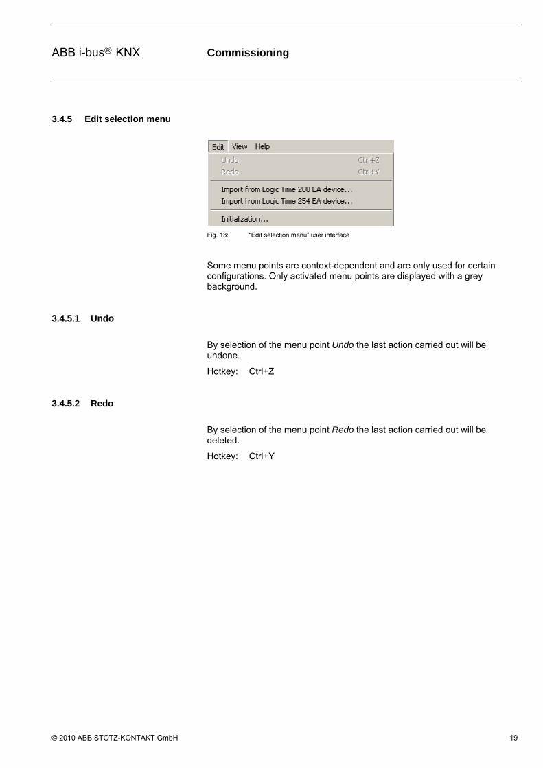
Fig. 13: “Edit selection menu” user interface
Some menu points are context-dependent and are only used for certain configurations. Only activated menu points are displayed with a grey background.
3.4.5.1 Undo
By selection of the menu point Undo the last action carried out will be undone.
Hotkey: Ctrl+Z
3.4.5.2 Redo
By selection of the menu point Redo the last action carried out will be deleted.
Hotkey: Ctrl+Y

Commissioning
© 2010 ABB STOTZ-KONTAKT GmbH 20
ABB i-bus KNX
3.4.5.3 Copy
By selecting the menu item Copy, the elements or groups of elements that are currently marked in the parameter editor are copied into the invisible clipboard. The links within the copied elements are also copied. Group addresses are not accepted.
Note: Only references to the marked elements are stored in the clipboard. The actual copy process for the elements only occurs with Paste.
Hotkey: Ctrl+C
Marked elements can be copied using the symbols (icons) in the toolbar (see chapter Toolbar) as well as using the context menu.
The context menu appears when the right mouse button is pressed in the parameter editor. The functions are context-dependent and are only activated with certain configurations. Non-activated menu items are shown in gray.
Fig. 14: Context menu Copy - Paste
After selecting Copy, the marked elements are copied into the invisible clipboard.
3.4.5.4 Paste
By selection of the menu item Paste, the current content of the clipboard is pasted into the parameter editor. The pasted copy is as close as possible to the original and useful. The links within the copied elements are also copied. Group addresses are not accepted. The copies are pasted slightly inclined below the original in the parameter editor. The newly pasted elements are marked automatically and accepted instead of the old elements in the clipboard. This assures continuous numbering of the elements in the clipboard.
Note: All elements automatically receive continuous numbering, e.g. the first input = E1 or the first AND gate = 1. When pasted, copied elements are assigned with the next highest number, e.g. with inputs = E2, with renewed paste = E3 etc. or with AND gates = 2, with renewed paste = 3, etc.
Hotkey: Ctrl+V
Marked elements can be pasted using the symbols (icons) in the toolbar (see chapter Toolbar) as well as using the context menu.
Commissioning
© 2010 ABB STOTZ-KONTAKT GmbH 21
ABB i-bus KNX
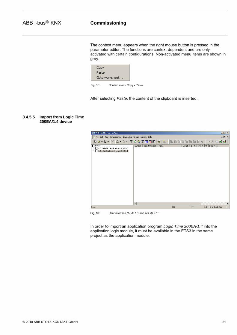
The context menu appears when the right mouse button is pressed in the parameter editor. The functions are context-dependent and are only activated with certain configurations. Non-activated menu items are shown in gray.
Fig. 15: Context menu Copy - Paste
After selecting Paste, the content of the clipboard is inserted.
3.4.5.5 Import from Logic Time 200EA/1.4 device
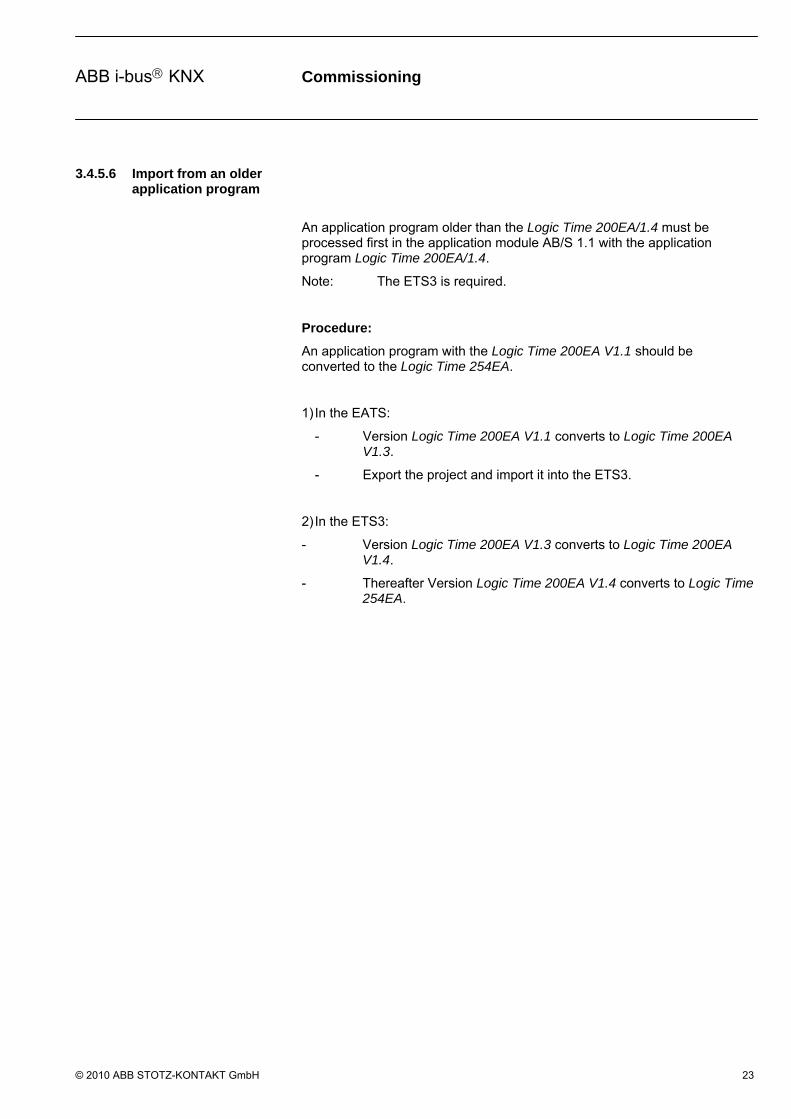
Fig. 16: User interface “AB/S 1.1 and ABL/S 2.1”
In order to import an application program Logic Time 200EA/1.4 into the application logic module, it must be available in the ETS3 in the same project as the application module.

Commissioning
© 2010 ABB STOTZ-KONTAKT GmbH 22
ABB i-bus KNX
Fig. 17: User interface “Import from Logic Time 200 EA/1.4” device
Thereafter, open the ABL/S and under Edit, add the Import from Logic Time 200 EA device.
Fig. 18: User interface “Import Logic Time 200 EA/1.4 configuration”
Device with “Logic Time 200 EA/1.4”
Only select the application program to be imported from the selection list.
Copy Associations
If the checkbox is set under Copy Associations, the entire information, e.g. group addresses of the application program, is copied into the new application program.
Import buttons
The settings are copied and the parameter window closes via the button.
Cancel button
The function is interrupted and the parameter window closes via the button.
Commissioning
© 2010 ABB STOTZ-KONTAKT GmbH 23
ABB i-bus KNX
3.4.5.6 Import from an older application program
An application program older than the Logic Time 200EA/1.4 must be processed first in the application module AB/S 1.1 with the application program Logic Time 200EA/1.4.
Note: The ETS3 is required.
Procedure:
An application program with the Logic Time 200EA V1.1 should be converted to the Logic Time 254EA.
1) In the EATS:
- Version Logic Time 200EA V1.1 converts to Logic Time 200EA V1.3.
- Export the project and import it into the ETS3.
2) In the ETS3:
- Version Logic Time 200EA V1.3 converts to Logic Time 200EA V1.4.
- Thereafter Version Logic Time 200EA V1.4 converts to Logic Time 254EA.

Commissioning
© 2010 ABB STOTZ-KONTAKT GmbH 24
ABB i-bus KNX
3.4.5.7 Import from Logic Time 254EA device
Fig. 19: User interface “Import from Logic Time 254 EA - successful”
By selection of the menu point Import from Logic Time 254 EA device..., an existing application program which has been created in the application module can be imported into the current application module logic.
Select a source device from the list below:
The data is copied to the target device from this source device.
Copy configuration into target device:
This parameter is inactive. The target device is shown here.
Copy associations
If the checkbox is set under Copy associations, the group addresses are also linked.
Start button
The settings are copied and the parameter window closes via the button.
Commissioning
© 2010 ABB STOTZ-KONTAKT GmbH 25
ABB i-bus KNX
3.4.5.8 Initialization
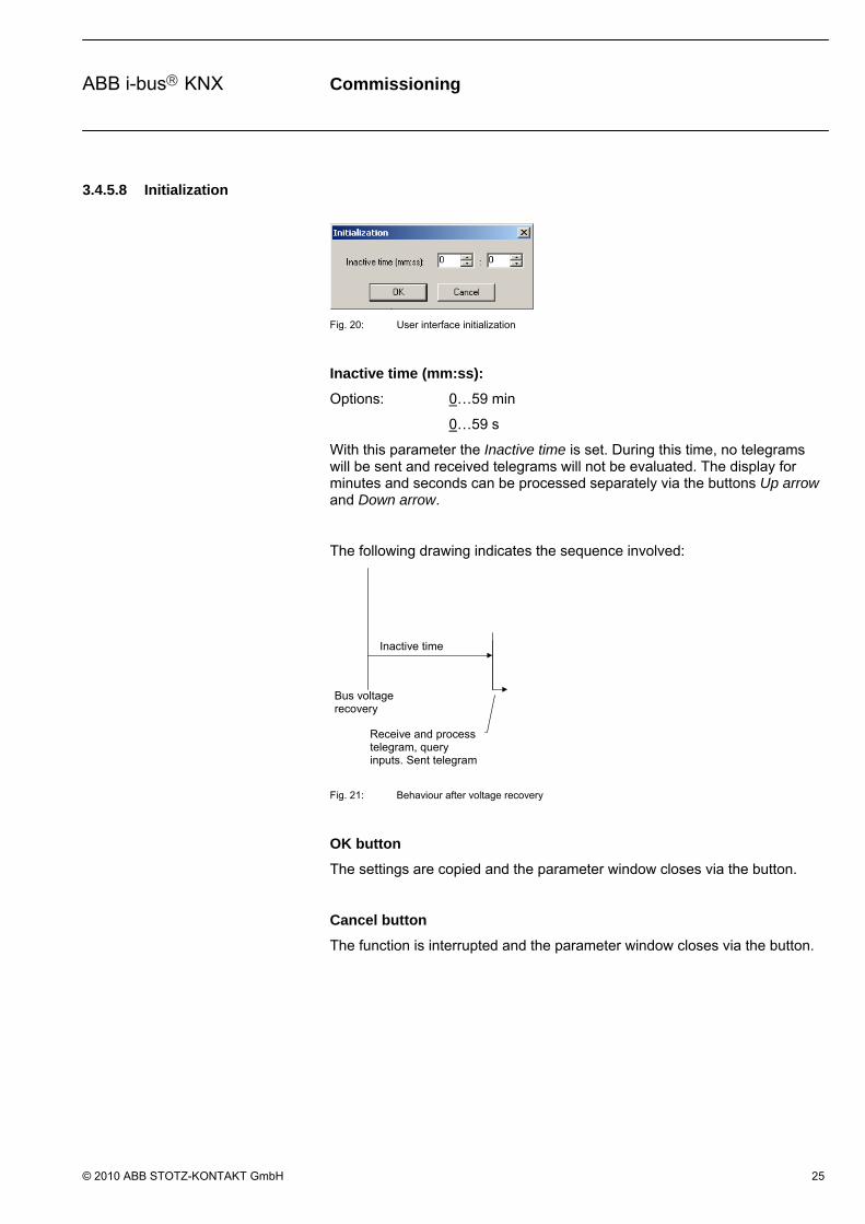
Fig. 20: User interface initialization
Inactive time (mm:ss):
Options: 0…59 min
0…59 s
With this parameter the Inactive time is set. During this time, no telegrams will be sent and received telegrams will not be evaluated. The display for minutes and seconds can be processed separately via the buttons Up arrow and Down arrow.
The following drawing indicates the sequence involved:
Bus voltage recovery
Inactive time
Receive and process telegram, query inputs. Sent telegram
Fig. 21: Behaviour after voltage recovery
OK button
The settings are copied and the parameter window closes via the button.
Cancel button
The function is interrupted and the parameter window closes via the button.
Commissioning
© 2010 ABB STOTZ-KONTAKT GmbH 26
ABB i-bus KNX
3.4.6 View selection menu
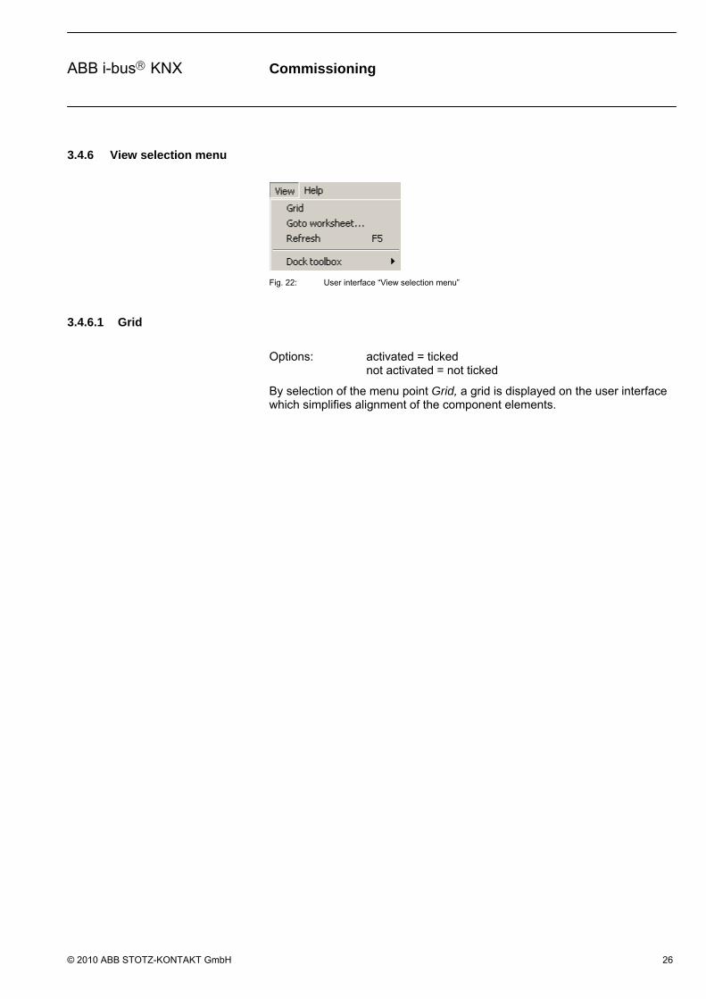
Fig. 22: User interface “View selection menu”
3.4.6.1 Grid
Options: activated = ticked not activated = not ticked
By selection of the menu point Grid, a grid is displayed on the user interface which simplifies alignment of the component elements.

Commissioning
© 2010 ABB STOTZ-KONTAKT GmbH 27
ABB i-bus KNX
3.4.6.2 Goto worksheet
Fig. 23: User interface “Goto worksheet…”
By selection of the menu point Goto worksheet..., a dialog window for selection of a worksheet opens.
More complex parameterisation and a smaller monitor size can quickly lead to a very unclear view of the graphic parameterisation. Worksheet management is used in order to effectively design this. It describes a part of the graphical parameterisation and is implemented in the form of jump labels.
Goto button
The button is used to jump to the selected worksheet and the parameter window closes.
Cancel button
The function is interrupted and the parameter window closes via the button.
3.4.6.3 Refresh
By selection of the Refresh menu point, a graphic representation can be reloaded and displayed.
Hotkey: F5

Commissioning
© 2010 ABB STOTZ-KONTAKT GmbH 28
ABB i-bus KNX
3.4.6.4 Dock toolbox
Fig. 24: User interface “Dock toolbox”
Options: activated = ticked not activated = not ticked
By selection of the menu point Dock toolbox on, the user can individually select if the toolbar is displayed at the top, left, right or bottom of the parameter window.
3.4.7 Help selection menu
Fig. 25: User interface “Help selection menu”
3.4.7.1 Help index F1
By selection of the menu point Help index..., the manual is displayed in PDF format.
Hotkey: F1
3.4.7.2 About
Fig. 26: User interface “About…”
By selection of the menu point About..., information concerning the application program and the manufacturer of the device are displayed.
OK button
The parameter window is closed via the button.
Commissioning
© 2010 ABB STOTZ-KONTAKT GmbH 29
ABB i-bus KNX
3.4.8 Toolbar
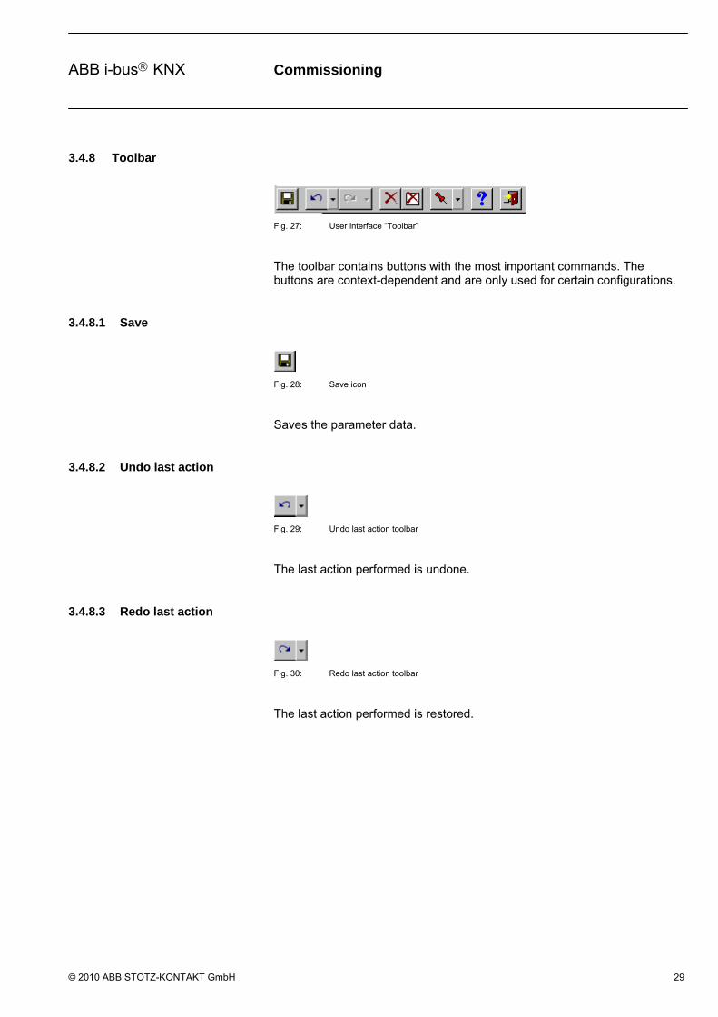
Fig. 27: User interface “Toolbar”
The toolbar contains buttons with the most important commands. The buttons are context-dependent and are only used for certain configurations.
3.4.8.1 Save
Fig. 28: Save icon
Saves the parameter data.
3.4.8.2 Undo last action
Fig. 29: Undo last action toolbar
The last action performed is undone.
3.4.8.3 Redo last action
Fig. 30: Redo last action toolbar
The last action performed is restored.

Commissioning
© 2010 ABB STOTZ-KONTAKT GmbH 30
ABB i-bus KNX
3.4.8.4 Copy
Fig. 31: Symbol - Copy (inactive)
If an element is not marked, the Copy symbol is inactive.
Fig. 32: Symbol - Copy (active)
The Copy symbol is active after at least one element has been marked.
By actuating the symbol item Copy, the elements or groups of elements that are currently marked in the parameter editor are copied into the invisible clipboard. The links within the copied elements are also copied. Group addresses are not accepted.
Note: Only references to the marked elements are stored in the clipboard. The actual copy process for the elements only occurs with Paste.
Hotkey: Ctrl+C
Marked elements can also be edited using the selection menu Edit (see Edit selection menu) and copied using the context menu.
The context menu appears when the right mouse button is pressed in the parameter editor. The functions are context-dependent and are only activated with certain configurations. Non-activated menu items are shown in gray.
Fig. 33: Context menu Copy - Paste
After selecting Copy, the marked elements are copied into the invisible clipboard.
3.4.8.5 Paste
Fig. 34: Symbol - Paste (inactive)
If the clipboard is empty, the Paste symbol is inactive.
Fig. 35: Symbol - Paste (active)
The Paste symbol is active if at least one element is located in the clipboard.
By actuating the symbol Paste, the current content of the clipboard is pasted into the parameter editor. The pasted copy is as close as possible to the original and useful. The links within the copied elements are also copied. Group addresses are not accepted.
The copies are pasted slightly inclined below the original in the parameter

Commissioning
© 2010 ABB STOTZ-KONTAKT GmbH 31
ABB i-bus KNX
editor. The newly pasted elements are marked automatically and accepted instead of the old elements in the clipboard. This assures continuous numbering of the elements in the clipboard.
Note: All elements automatically receive continuous numbering, e.g. the first input = E1. During a paste the copied elements receive the next highest number, e.g. for inputs = E2, with a renewed paste = E3 etc. or for AND gates = 2, with renewed paste = 3, etc.
Marked elements can also be edited using the selection menu Edit (see Edit selection menu) and pasted using the context menu.
The context menu appears when the right mouse button is pressed in the parameter editor. The functions are context-dependent and are only activated with certain configurations. Non-activated menu items are shown in gray.
Fig. 36: Context menu Copy - Paste
After selecting Paste, the content of the clipboard is inserted.
3.4.8.6 Delete the selected element or link
Fig. 37: Delete the selected element or link icon
Deletes the selected objects or a selected link.
3.4.8.7 Delete all objects and links
Fig. 38: Delete all objects and links icon
Deletes all objects and links.
Commissioning
© 2010 ABB STOTZ-KONTAKT GmbH 32
ABB i-bus KNX
3.4.8.8 Define toolbar pin on position
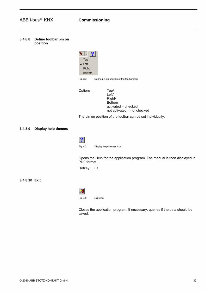
Fig. 39: Define pin on position of the toolbar icon
Options: Top/ Left/ Right/ Bottom activated = checked not activated = not checked
The pin on position of the toolbar can be set individually.
3.4.8.9 Display help themes
Fig. 40: Display help themes icon
Opens the Help for the application program. The manual is then displayed in PDF format.
Hotkey: F1
3.4.8.10 Exit
Fig. 41: Exit icon
Closes the application program. If necessary, queries if the data should be saved.
Commissioning
© 2010 ABB STOTZ-KONTAKT GmbH 33
ABB i-bus KNX
3.4.8.11 Hotkey selection
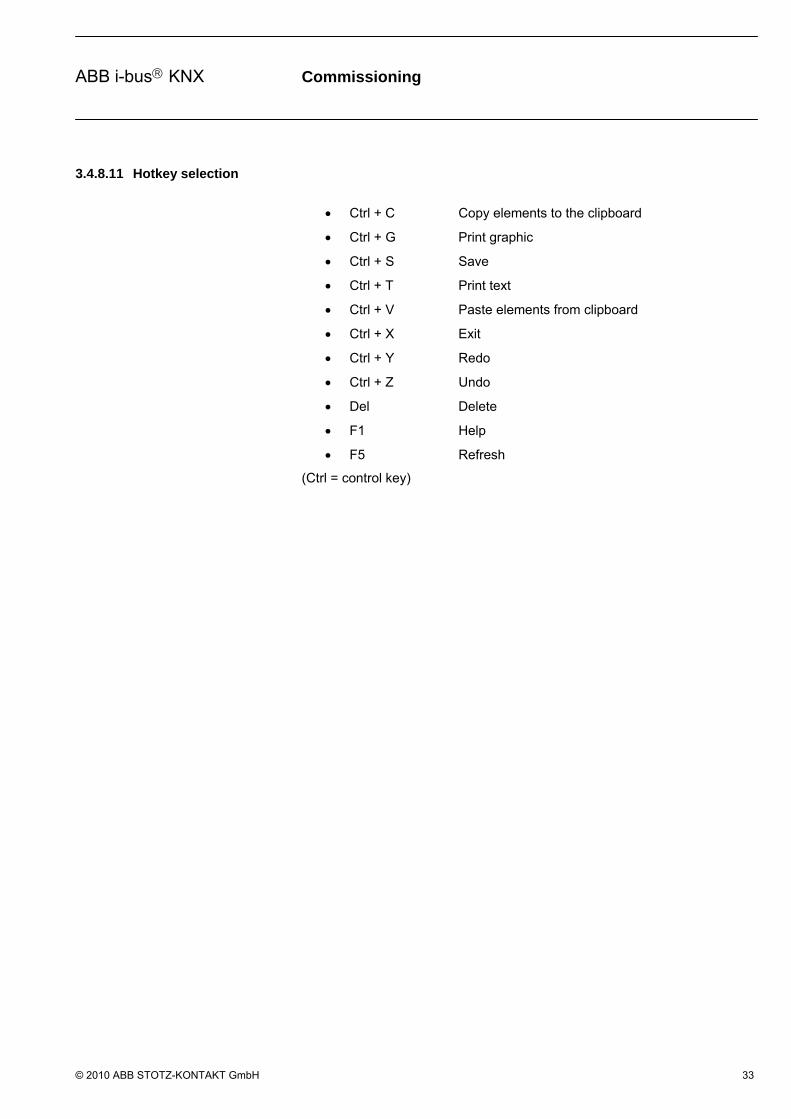
Ctrl + C Copy elements to the clipboard
Ctrl + G Print graphic
Ctrl + S Save
Ctrl + T Print text
Ctrl + V Paste elements from clipboard
Ctrl + X Exit
Ctrl + Y Redo
Ctrl + Z Undo
Del Delete
F1 Help
F5 Refresh
(Ctrl = control key)

Commissioning
© 2010 ABB STOTZ-KONTAKT GmbH 34
ABB i-bus KNX
3.4.9 Toolbar
Fig. 42: Toolbar
The toolbar contains inputs, outputs, logical elements as well as the function worksheet.
Note: The logic in the ABL/S 2.1 operates according to the dynamic principle, i.e. should a new telegram be received, all results of the elements dependent on the telegram are recalculated and the outputs are updated if they cannot be parameterised.
3.4.9.1 Input
Fig. 43: Input
Corresponds with the communication objects in the ETS3 and can be linked to the logical elements. 254 communication objects are available for inputs and outputs. The communication object type can assume different forms.
Commissioning
© 2010 ABB STOTZ-KONTAKT GmbH 35
ABB i-bus KNX
3.4.9.2 Output
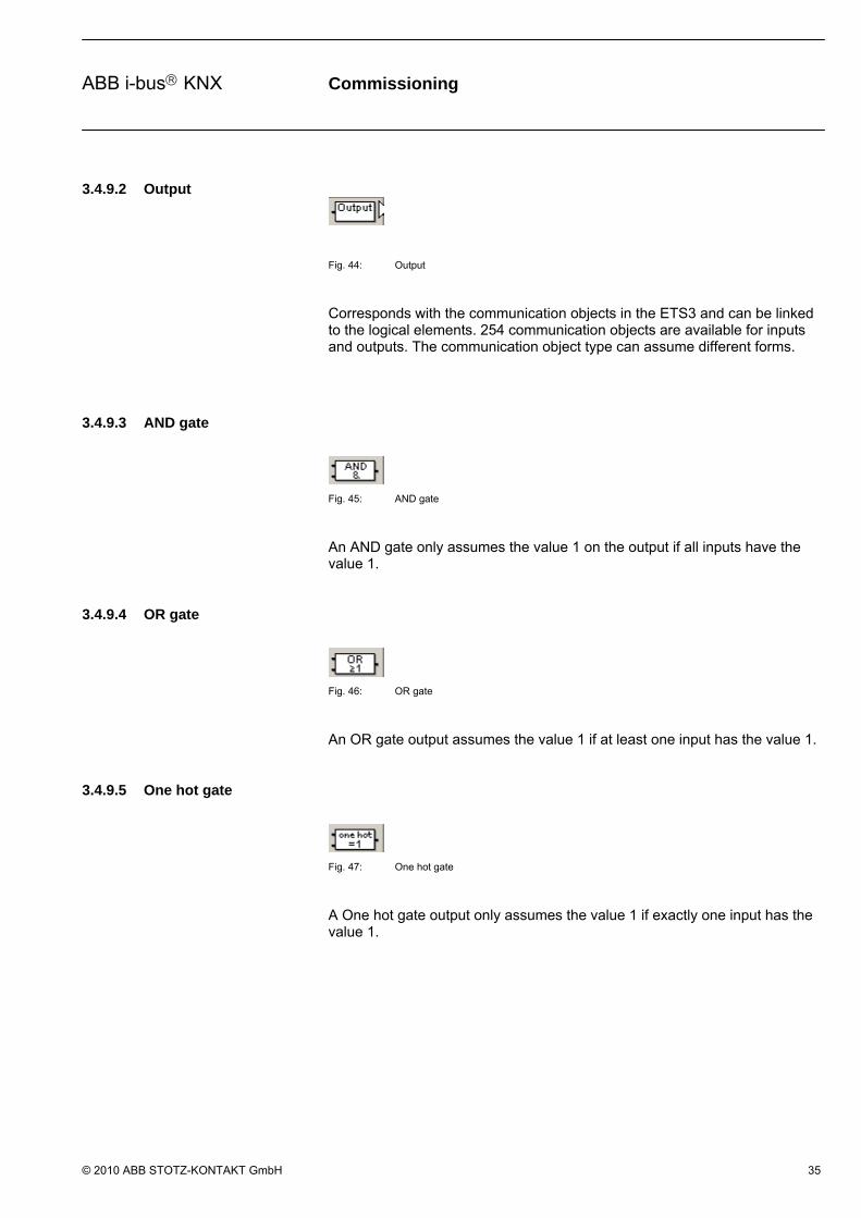
Fig. 44: Output
Corresponds with the communication objects in the ETS3 and can be linked to the logical elements. 254 communication objects are available for inputs and outputs. The communication object type can assume different forms.
3.4.9.3 AND gate
Fig. 45: AND gate
An AND gate only assumes the value 1 on the output if all inputs have the value 1.
3.4.9.4 OR gate
Fig. 46: OR gate
An OR gate output assumes the value 1 if at least one input has the value 1.
3.4.9.5 One hot gate
Fig. 47: One hot gate
A One hot gate output only assumes the value 1 if exactly one input has the value 1.

Commissioning
© 2010 ABB STOTZ-KONTAKT GmbH 36
ABB i-bus KNX
3.4.9.6 Gate
Fig. 48: Gate
A Gate has one input, one output and one control input. If an event occurs at the input and the gate is enabled, it can transfer the value at the input to the output. If the gate is disabled, there is no reaction.
3.4.9.7 Bidirectional gate
Fig. 49: Bidirectional gate
The Bidirectional gate features an input and an output, as well as a control input. The enabled gate can transfer a communication object value in both directions.
3.4.9.8 Timer
Fig. 50: Timer
A Timer has an input and an output. The input also has another filter. If an event occurs at the input, the timer can transfer the value at the input to the output with a time delay.
3.4.9.9 Staircase light
Fig. 51: Staircase light
The Staircaselight function consists of an input, which is simultaneously an output. The input and output signal is reset after the adjustable time has timed out. If there is a new input signal within the time, the output signal remains at the existing value and the time is restarted.

Commissioning
© 2010 ABB STOTZ-KONTAKT GmbH 37
ABB i-bus KNX
3.4.9.10 Comparator
Fig. 52: Comparator
A Comparator comprises of two inputs, an output and an overflow output. It compares two input values with one another after an adjustable comparator operation. If the comparative condition is fulfilled, the output sends a 1, if it is not fulfilled it sends a 0.
If the value range is exceeded during a comparison, a fault is indicated on the overflow output.
3.4.9.11 Worksheet
Fig. 53: Worksheet
A Worksheet is a text field. It describes a part of the graphical parameterisation and is implemented in the form of jump labels.

Commissioning
© 2010 ABB STOTZ-KONTAKT GmbH 38
ABB i-bus KNX
3.5 Working in the worksheet
The design of the logic functions is carried out in the worksheet and implemented in a graphic function chart based on DIN 40900.
The engineering design proceeds as follows:
- Place the input - Implement the logic function - Place the output - Establish the connections - Edit the parameters of the individual elements
3.5.1 Assigning new elements
Fig. 54: Assigning new elements
With the help of the toolbar, on the left of the new elements, e.g. inputs, outputs and logical functions can be created. The corresponding element is selected with the left mouse button in the toolbar and placed with the pressed button on the worksheet. Several elements of the selected type can be added if the Ctrl key is held pressed during insertion.
Note: In order to align the elements, the grid can be displayed on the View menu. Furthermore, the set print area should be observed when placing elements by calling up the Print preview and Graphic preview.

Commissioning
© 2010 ABB STOTZ-KONTAKT GmbH 39
ABB i-bus KNX
3.5.2 Copying of elements Elements can be copied into the invisible clipboard via the selection menu Edit, using a hotkey or via the context menu.
By selecting the menu item Copy in the Edit selection menu, the elements or groups of elements that are currently marked in the parameter editor are copied into the invisible clipboard. The links within the copied elements are also copied. Group addresses are not accepted.
Note: Only references to the marked elements are stored in the clipboard. The actual copy process for the elements only occurs with Paste.
Fig. 55: Symbol - Copy (active)
If an element is not marked, the Copy symbol is inactive. The Copy symbol is active after at least one element has been marked.
By pressing the symbol Copy, the marked elements are copied into the invisible clipboard.
Hotkey: Ctrl+C
The context menu appears when the right mouse button is pressed in the parameter editor. The functions are context-dependent and are only activated with certain configurations. Non-activated menu items are shown in gray.
Fig. 56: Context menu Copy - Paste
After selecting Copy, the marked elements are copied into the invisible clipboard.
3.5.3 Pasting of elements The content of the clipboard can be pasted using the selection menu Edit, symbols in the toolbar, hotkey or via the context menu in the parameter editor.
By selecting the menu item Paste in the Edit menu, the current content of the clipboard is pasted into the parameter editor. The pasted copy is as close as possible to the original and useful. The links within the copied elements are also copied. Group addresses are not accepted. The copies are pasted slightly inclined below the original in the parameter editor. The newly pasted elements are marked automatically and accepted instead of the old elements in the clipboard. This assures continuous numbering of the elements in the clipboard.
Note: All elements automatically receive continuous numbering, e.g. the first input = E1 or the first AND gate = 1. When pasted, copied elements are assigned with the next highest number, e.g. with inputs = E2, with renewed paste = E3 etc. or with AND gates = 2, with renewed paste = 3, etc.

Commissioning
© 2010 ABB STOTZ-KONTAKT GmbH 40
ABB i-bus KNX
Fig. 57: Symbol - Paste (active)
If the clipboard is empty, the Paste symbol is inactive. The Paste symbol is active if at least one element is located in the clipboard.
Hotkey: Ctrl+V
The context menu appears when the right mouse button is pressed in the parameter editor. The functions are context-dependent and are only activated with certain configurations. Non-activated menu items are shown in gray.
Fig. 58: Context menu Copy - Paste
After selecting Paste, the content of the clipboard is inserted.
3.5.4 Selection of elements
The element can be selected in order to move or delete it. This is done by clicking on the element with the left mouse button. This is also the case when selecting a line of association.
3.5.5 Multiple selection of elements
Several elements can be selected at once, e.g. for moving or deleting. The elements are selected using the mouse. Press the left mouse button and drag out a rectangle, keeping the button pressed down. Or keep the Ctrl button pressed and click on each of the required elements with the left mouse button. Thus, several elements situated next to one another can be marked. The selected elements are then displayed in colour.

Commissioning
© 2010 ABB STOTZ-KONTAKT GmbH 41
ABB i-bus KNX
3.5.6 Moving elements in the worksheet
The visible area of the worksheet can be moved using the scrollbars on the right hand side and at the bottom of the window. Elements can also be moved to a position outside the visible area. Select the corresponding element with the left mouse button and move the mouse pointer in the required direction keeping the button pressed down. The visible area of the worksheet moves if the limits of the visible area are crossed over. If necessary, the worksheet is enlarged.
Note: The set print area should be observed when placing elements by calling up the Print preview and Graphic preview.
Commissioning
© 2010 ABB STOTZ-KONTAKT GmbH 42
ABB i-bus KNX
3.5.7 Linking functions
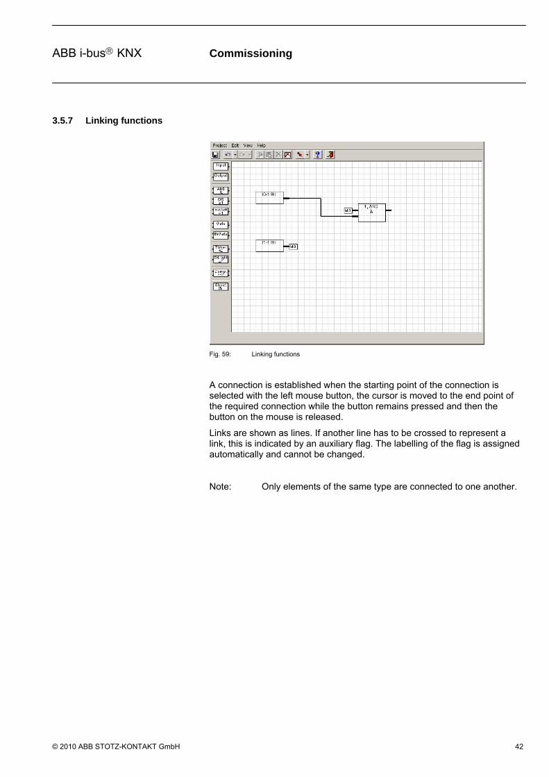
Fig. 59: Linking functions
A connection is established when the starting point of the connection is selected with the left mouse button, the cursor is moved to the end point of the required connection while the button remains pressed and then the button on the mouse is released.
Links are shown as lines. If another line has to be crossed to represent a link, this is indicated by an auxiliary flag. The labelling of the flag is assigned automatically and cannot be changed.
Note: Only elements of the same type are connected to one another.

Commissioning
© 2010 ABB STOTZ-KONTAKT GmbH 43
ABB i-bus KNX
The parameter window Link to Interface becomes active with the following procedure:
- Select the element and open the context menu with the right mouse button. Then select the command Link to Interface ….
Fig. 60: Parameter window “Link to interface”
In order to simplify the creation of links for larger projects, e.g. if elements which are not all in the same visual area are to be linked, it is possible to link an element using the command Link to Interface.
OK button
The settings are copied and the parameter window closes via the button.
Cancel button
The function is interrupted and the parameter window closes via the button.
3.5.8 Deleting links
Links are deleted:
- By selecting the link and pressing the Del button
- By selecting the connection, pressing the right mouse button and selecting the Delete command.
Note: Once inputs, outputs and functions have been changed in the worksheet, the links are automatically updated.
Commissioning
© 2010 ABB STOTZ-KONTAKT GmbH 44
ABB i-bus KNX
3.5.9 Displaying links
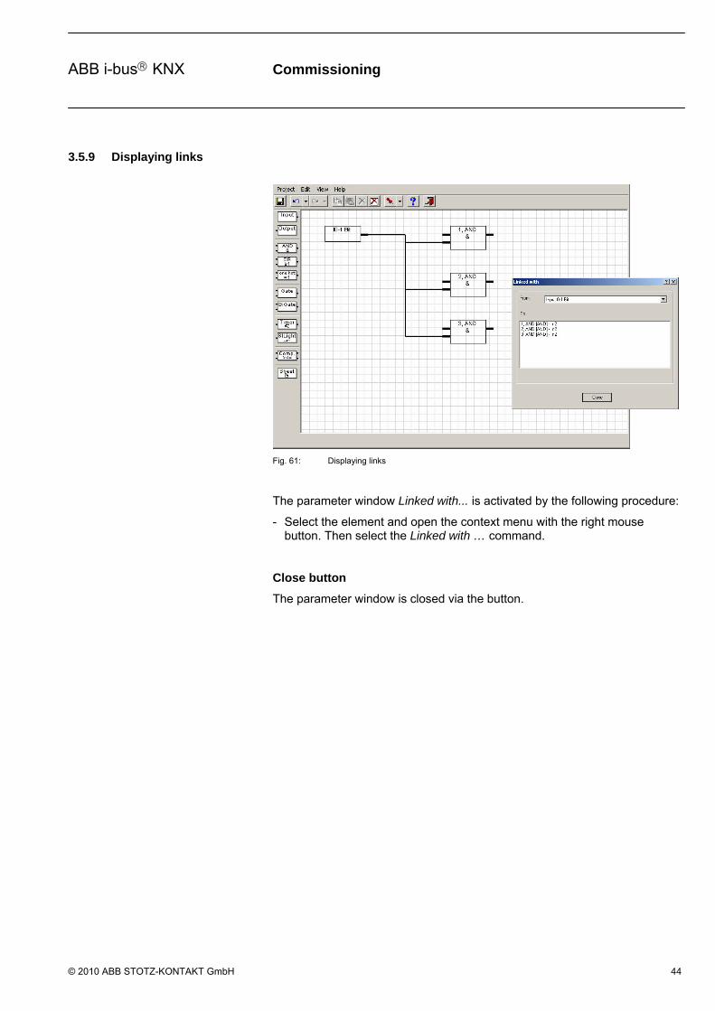
Fig. 61: Displaying links
The parameter window Linked with... is activated by the following procedure:
- Select the element and open the context menu with the right mouse button. Then select the Linked with … command.
Close button
The parameter window is closed via the button.

Commissioning
© 2010 ABB STOTZ-KONTAKT GmbH 45
ABB i-bus KNX
3.6 Functions
Note: The standard settings for the options are underlined, e.g. option: yes/no.
3.6.1 Inputs and outputs
The inputs and outputs in the application program correspond with the communication objects in the ETS3. They are visible in the ETS3 and can be processed there.
3.6.1.1 Input
Fig. 62: Input
The connection for the input is on the right of the element.
Note: In the event of a bus voltage failure, the values of the input objects are stored for at least an hour. With a bus voltage failure that is longer than one hour in duration, the values of the input objects are lost. A check is therefore made in the ABL/S 2.1 on bus voltage recovery before processing the values of the input objects, to determine whether data loss has occurred in the meantime.
Commissioning
© 2010 ABB STOTZ-KONTAKT GmbH 46
ABB i-bus KNX
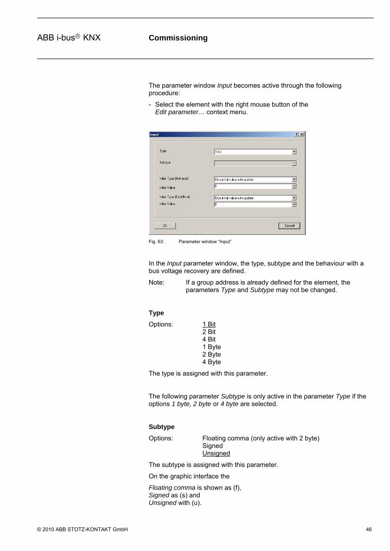
The parameter window Input becomes active through the following procedure:
- Select the element with the right mouse button of the Edit parameter… context menu.
Fig. 63: Parameter window “Input”
In the Input parameter window, the type, subtype and the behaviour with a bus voltage recovery are defined.
Note: If a group address is already defined for the element, the parameters Type and Subtype may not be changed.
Type
Options: 1 Bit 2 Bit 4 Bit 1 Byte 2 Byte 4 Byte
The type is assigned with this parameter.
The following parameter Subtype is only active in the parameter Type if the options 1 byte, 2 byte or 4 byte are selected.
Subtype
Options: Floating comma (only active with 2 byte) Signed Unsigned
The subtype is assigned with this parameter.
On the graphic interface the
Floating comma is shown as (f), Signed as (s) and Unsigned with (u).
Commissioning
© 2010 ABB STOTZ-KONTAKT GmbH 47
ABB i-bus KNX
Initial Type (Hot boot)
Options: Use value before bus voltage dropped without update Use initial value without update Use value before bus voltage dropped with update Use initial value with update Ask bus for value
Under …with update… should be understood as a telegram with preset value simulated on the input. Thereafter, the calculation of the input via the linked function to the output occurs.
The behaviour of the parameter can be compared with a device warm start.
What is a Hot boot?
If the saved values are still available, the Application Unit Logic leads to a so-called Hot boot at bus voltage recovery, i.e. it can still operate with the saved data, but can still use the predefined data or read the relevant data for them from other bus devices.
Without update… can be understood to mean that the input assumes the value before the reset or the preset value. With the next event (telegram) to any input, which is associated with this function, the function is calculated with this value.
The following parameter Initial Value is only active, if in the parameter Initial Type (Hot boot), the options Use initial value without update or Use initial value with update have been selected.
Initial Value
Different settings are possible in the options depending on the Type and Subtype, which have been selected.
Options: 1 Bit = 0/1 2 Bit = 0…3 4 Bit = 0…15
1 Byte Unsigned = 0…255 1 Byte Signed = -128…0…127
2 Byte Floating point 2 Byte Unsigned = 0…65.535 2 Byte Signed = -32.768…0…32.767
4 Byte Unsigned = 0…4.294.967.295 4 Byte Signed = -2.147.483.648…0…2.147.483.647
Commissioning
© 2010 ABB STOTZ-KONTAKT GmbH 48
ABB i-bus KNX
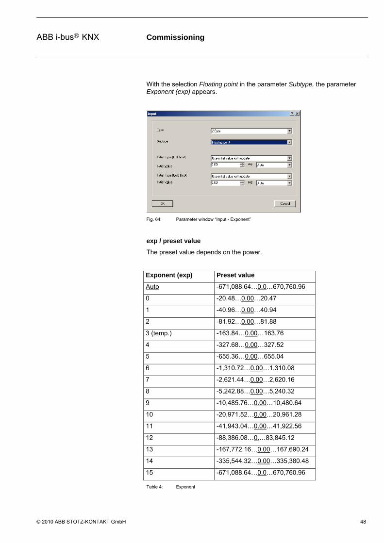
With the selection Floating point in the parameter Subtype, the parameter Exponent (exp) appears.
Fig. 64: Parameter window “Input - Exponent”
exp / preset value
The preset value depends on the power.
Exponent (exp) Preset value
Auto -671,088.64…0.0…670,760.96
0 -20.48…0.00…20.47
1 -40.96…0.00…40.94
2 -81.92…0.00…81.88
3 (temp.) -163.84…0.00…163.76
4 -327.68…0.00…327.52
5 -655.36…0.00…655.04
6 -1,310.72…0.00…1,310.08
7 -2,621.44…0.00…2,620.16
8 -5,242.88…0.00…5,240.32
9 -10,485.76…0.00…10,480.64
10 -20,971.52…0.00…20,961.28
11 -41,943.04…0.00…41,922.56
12 -88,386.08…0.…83,845.12
13 -167,772.16…0.00…167,690.24
14 -335,544.32…0.00…335,380.48
15 -671,088.64…0.0…670,760.96
Table 4: Exponent

Commissioning
© 2010 ABB STOTZ-KONTAKT GmbH 49
ABB i-bus KNX
Initial Type (Cold boot)
Options: Use initial value without update Use initial value with update Ask bus for value
Under …with update… should be understood as a telegram with preset value simulated on the input. Thereafter, the calculation of the input via the linked function to the output occurs.
The behaviour of the parameter can be compared with a device cold start.
What is a Cold Boot?
In case of a data loss, the Application Unit Logic undertakes a so-called Cold Boot with bus voltage recovery, i.e. it can no longer access saved data and must operate either with predefined data or must read the data relevant for itself from other bus devices.
Without update… can be understood to mean that the input assumes the value before the reset or the preset value. With the next event (telegram) to any input, which is associated with this function, the function is calculated with this value.
The following parameter Initial Value is only active if in the parameter Initial Type (Cold boot) the options Use initial value without update or Use initial value with update have been selected.
Initial Value
Different settings are possible in the options depending on the Type and Subtype which have been selected.
Options: 1 Bit = 0/1 2 Bit = 0…3 4 Bit = 0…15
1 Byte Unsigned = 0…255 1 Byte Signed = -128…0…127
2 Byte Floating point 2 Byte Unsigned = 0…65.535 2 Byte Signed = -32.768…0…32.767
4 Byte Unsigned = 0…4.294.967.295 4 Byte Signed = -2.147.483.648…0…2.147.483.647

Commissioning
© 2010 ABB STOTZ-KONTAKT GmbH 50
ABB i-bus KNX
With the selection Floating point in the parameter Subtype, the parameter Exponent (exp) appears.
Fig. 65: Parameter window “Input - Exponent”
exp / preset value
The preset value depends on the power.
Exponent (exp) Preset value
Auto -671,088.64…0.0…670,760.96
0 -20.48…0.00…20.47
1 -40.96…0.00…40.94
2 -81.92…0.00…81.88
3 (temp.) -163.84…0.00…163.76
4 -327.68…0.00…327.52
5 -655.36…0.00…655.04
6 -1,310.72…0.00…1,310.08
7 -2,621.44…0.00…2,620.16
8 -5,242.88…0.00…5,240.32
9 -10,485.76…0.00…10,480.64
10 -20,971.52…0.00…20,961.28
11 -41,943.04…0.00…41,922.56
12 -88,386.08…0.…83,845.12
13 -167,772.16…0.00…167,690.24
14 -335,544.32…0.00…335,380.48
15 -671,088.64…0.0…670,760.96
Table 5: Exponent

Commissioning
© 2010 ABB STOTZ-KONTAKT GmbH 51
ABB i-bus KNX
OK button
The settings are copied and the parameter window closes via the button.
Cancel button
The function is interrupted and the parameter window closes via the button.

Commissioning
© 2010 ABB STOTZ-KONTAKT GmbH 52
ABB i-bus KNX
3.6.1.2 Output
Fig. 66: Output
The connection for the output is on the left of the element.

Commissioning
© 2010 ABB STOTZ-KONTAKT GmbH 53
ABB i-bus KNX
The parameter window Output becomes active through the following procedure:
- Select the element with the right mouse button of the Edit parameter… context menu.
Fig. 67: Parameter window “Output”
In the Output parameter window, the type, subtype and sending of the output are defined.
Note: If a group address is already defined for the element, the parameters Type and Subtype may not be changed.
Type
Options: 1 Bit 2 Bit 4 Bit 1 Byte 2 Byte 4 Byte
The type is assigned with this parameter.

Commissioning
© 2010 ABB STOTZ-KONTAKT GmbH 54
ABB i-bus KNX
The following parameter Subtype is only active in the parameter Type if the options 1 byte, 2 byte or 4 byte are selected.
Subtype
Options: Floating point (only active with 2 byte) Signed Unsigned
The subtype is assigned with this parameter. In the graphic interface the Floating point is signified as (f), with Signed as (s) and Unsigned with (u).
1 Byte Unsigned = 0…255 1 Byte Signed = -128…127…
2 Byte Floating point, see table below 2 Byte Unsigned = 0…65.535 2 Byte Signed = -32.768…32.767…
4 Byte Unsigned = 0…4.294.967.295 4 Byte Signed = -2.147.483.648…2.147.483.647…
The output object type can appear as follows.
Exponent (exp) Object value
Auto -671,088.64…0.0…670,760.96
0 -20.48…0.00…20.47
1 -40.96…0.00…40.94
2 -81.92…0.00…81.88
3 (temp.) -163.84…0.00…163.76
4 -327.68…0.00…327.52
5 -655.36…0.00…655.04
6 -1,310.72…0.00…1,310.08
7 -2,621.44…0.00…2,620.16
8 -5,242.88…0.00…5,240.32
9 -10,485.76…0.00…10,480.64
10 -20,971.52…0.00…20,961.28
11 -41,943.04…0.00…41,922.56
12 -88,386.08…0.…83,845.12
13 -167,772.16…0.00…167,690.24
14 -335,544.32…0.00…335,380.48
15 -671,088.64…0.0…670,760.96
Table 6: Exponent
Commissioning
© 2010 ABB STOTZ-KONTAKT GmbH 55
ABB i-bus KNX
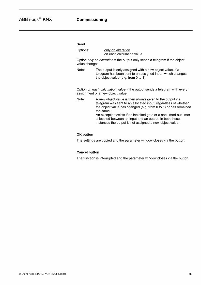
Send
Options: only on alteration on each calculation value
Option only on alteration = the output only sends a telegram if the object value changes.
Note: The output is only assigned with a new object value, if a telegram has been sent to an assigned input, which changes the object value (e.g. from 0 to 1).
Option on each calculation value = the output sends a telegram with every assignment of a new object value.
Note: A new object value is then always given to the output if a telegram was sent to an allocated input, regardless of whether the object value has changed (e.g. from 0 to 1) or has remained the same. An exception exists if an inhibited gate or a non timed-out timer is located between an input and an output. In both these instances the output is not assigned a new object value.
OK button
The settings are copied and the parameter window closes via the button.
Cancel button
The function is interrupted and the parameter window closes via the button.
Commissioning
© 2010 ABB STOTZ-KONTAKT GmbH 56
ABB i-bus KNX
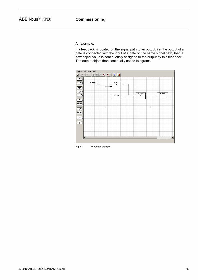
An example:
If a feedback is located on the signal path to an output, i.e. the output of a gate is connected with the input of a gate on the same signal path, then a new object value is continuously assigned to the output by this feedback. The output object then continually sends telegrams.
Fig. 68: Feedback example

Commissioning
© 2010 ABB STOTZ-KONTAKT GmbH 57
ABB i-bus KNX
3.6.1.3 Edit communication object
The parameter window Edit Object... is activated by the following procedure:
- By a double click on the input or output object.
- Select the input or output object and open Edit in the context menu with the right mouse button.
Fig. 69: Parameter window “Edit Object”
Name
Options: Input Object X/ Output Object X
Here the display indicates if it is an input object or an output object. At the same time, the number of the communication object is represented.
Function
Is empty
Type
Options: 1 Bit/ 2 Bit/ 4 Bit/ 1 Byte/ 2 Byte/ 4 Byte
Here the bit or byte type concerned is represented.

Commissioning
© 2010 ABB STOTZ-KONTAKT GmbH 58
ABB i-bus KNX
Priority
Options: Auto Normal Alarm
The Priority can be set to the following values:
Option Auto = low priority for time uncritical functions
Option Normal = normal priority for manually actuated functions
Option Alarm = high priority for time-critical functions
Flag Communication, Write, Update, Read and Transmit
Options: activated = ticked not activated = not ticked
The flags are set by activating the corresponding checkbox.
Function Abbreviation Selection Explanation
Communication C Set A normal communication connection is established between the communication objects and the bus.
Communication C Not set Telegrams are acknowledged, but the communication object will not be changed.
Write S Set The communication object value can be modified via the bus.
Write S Not set The communication object value cannot be modified via the bus.
Update A Set Value response telegrams are interpreted as a write command, the value of the communication object is updated.
Update A Not set Value response telegrams are not interpreted as a write command, the value of the communication object is not updated.
Read R Set The communication object value can be read via the bus.
Read R Not set The communication object value cannot be read via the bus.
Transmit T Set If (with the sensor) the communication object value is changed, a corresponding telegram is sent.
Transmit T Not set The communications object only sends a response telegram with a read request.
Table 7: Communication flags
Commissioning
© 2010 ABB STOTZ-KONTAKT GmbH 59
ABB i-bus KNX
Associated group addresses
The table is divided into Send, Maingroup, Middlegroup, Subgroup and Address.
Send
Option yes/no
Maingroup
The name of the main group is displayed here.
Middlegroup
The name of the middle group is displayed here.
Subgroup
The name of the lower group is displayed here.
Address
The group address is displayed here.
Set sending button
With this button a group address is marked as sent.
Note: The button becomes active as soon as a group address has been assigned.
Delete Association button
The assignment (link) between the group address and the communication object is deleted using this button
Note: The button becomes active as soon as a group address has been assigned.
OK button
The settings are copied and the parameter window closes via the button.
Cancel button
The function is interrupted and the parameter window closes via the button.

Commissioning
© 2010 ABB STOTZ-KONTAKT GmbH 60
ABB i-bus KNX
Standard button
Using this button, all flags are reset to the following standard settings.
C* W* R* T* U*
Input X X X
Output X X X
One output staircase light
X X X X
One output bidirectional gate
X X X X
Table 8: Standard settings of the flags
* C = communication W = write R = read T = transmit U = update
Note: The standard flags should be changed in a special case.
Parameter button
Via this button, you can access the parameter window input or output.
Commissioning
© 2010 ABB STOTZ-KONTAKT GmbH 61
ABB i-bus KNX
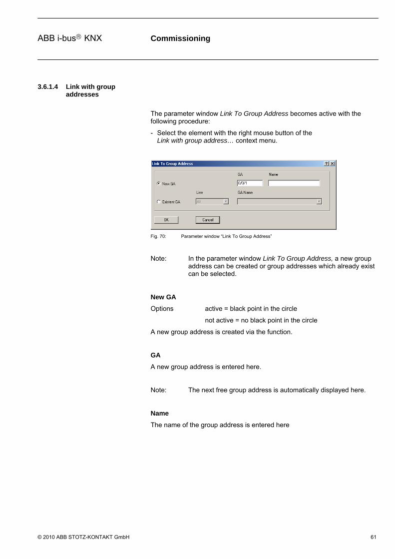
3.6.1.4 Link with group addresses
The parameter window Link To Group Address becomes active with the following procedure:
- Select the element with the right mouse button of the Link with group address… context menu.
Fig. 70: Parameter window “Link To Group Address”
Note: In the parameter window Link To Group Address, a new group address can be created or group addresses which already exist can be selected.
New GA
Options active = black point in the circle
not active = no black point in the circle
A new group address is created via the function.
GA
A new group address is entered here.
Note: The next free group address is automatically displayed here.
Name
The name of the group address is entered here

Commissioning
© 2010 ABB STOTZ-KONTAKT GmbH 62
ABB i-bus KNX
Existent GA
Options active = black point in the circle
not active = no black point in the circle
An existing group address is assigned via this function.
Line
Options: All Unused
The selection of existing group addresses can be sorted according to All, Line or Unused. If All is selected, all the existing group addresses are available for selection.
Note: After selection of links between input and output objects with the right mouse button, the assigned group addresses can be deleted under the Edit Object menu point.
OK button
The settings are copied and the parameter window closes via the button.
Cancel button
The function is interrupted and the parameter window closes via the button.
Commissioning
© 2010 ABB STOTZ-KONTAKT GmbH 63
ABB i-bus KNX
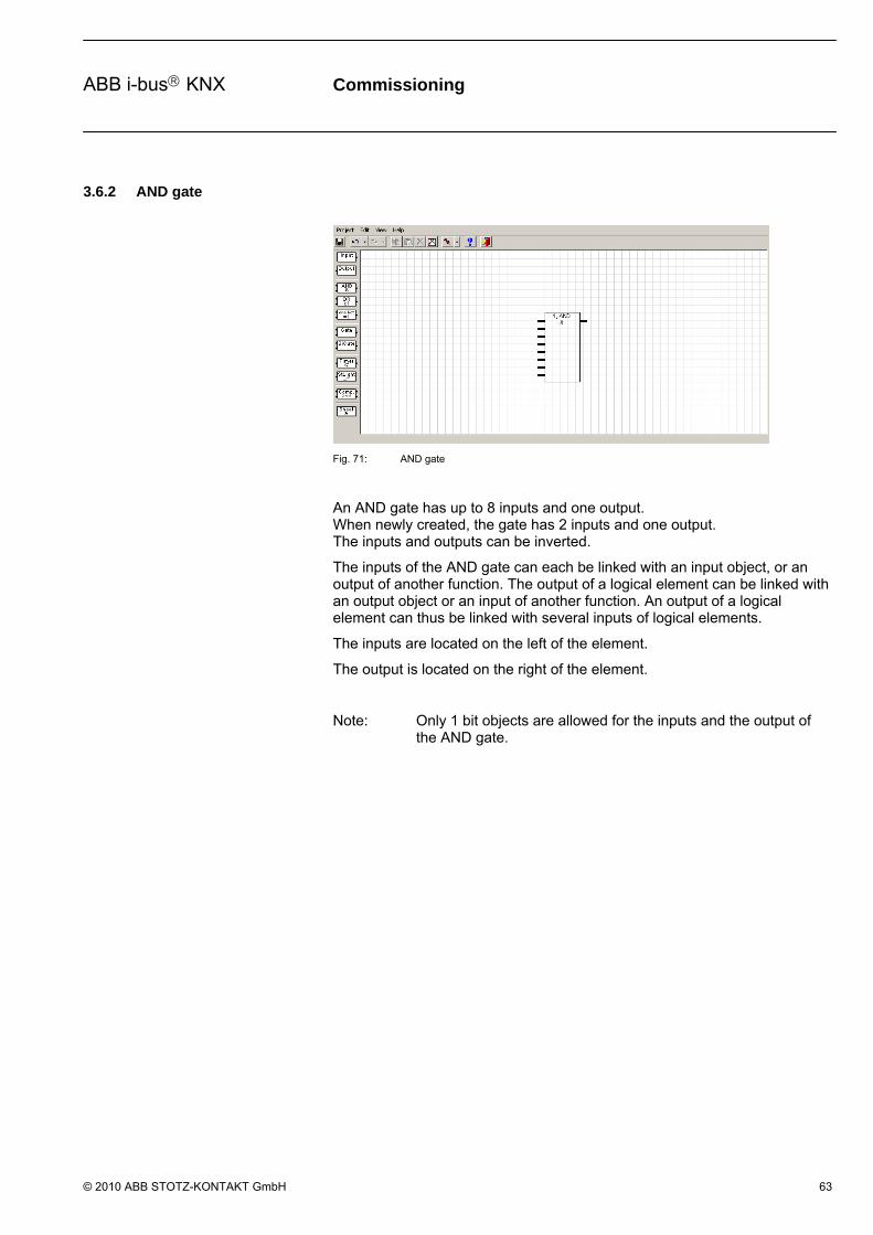
3.6.2 AND gate
Fig. 71: AND gate
An AND gate has up to 8 inputs and one output. When newly created, the gate has 2 inputs and one output. The inputs and outputs can be inverted.
The inputs of the AND gate can each be linked with an input object, or an output of another function. The output of a logical element can be linked with an output object or an input of another function. An output of a logical element can thus be linked with several inputs of logical elements.
The inputs are located on the left of the element.
The output is located on the right of the element.
Note: Only 1 bit objects are allowed for the inputs and the output of the AND gate.
Commissioning
© 2010 ABB STOTZ-KONTAKT GmbH 64
ABB i-bus KNX
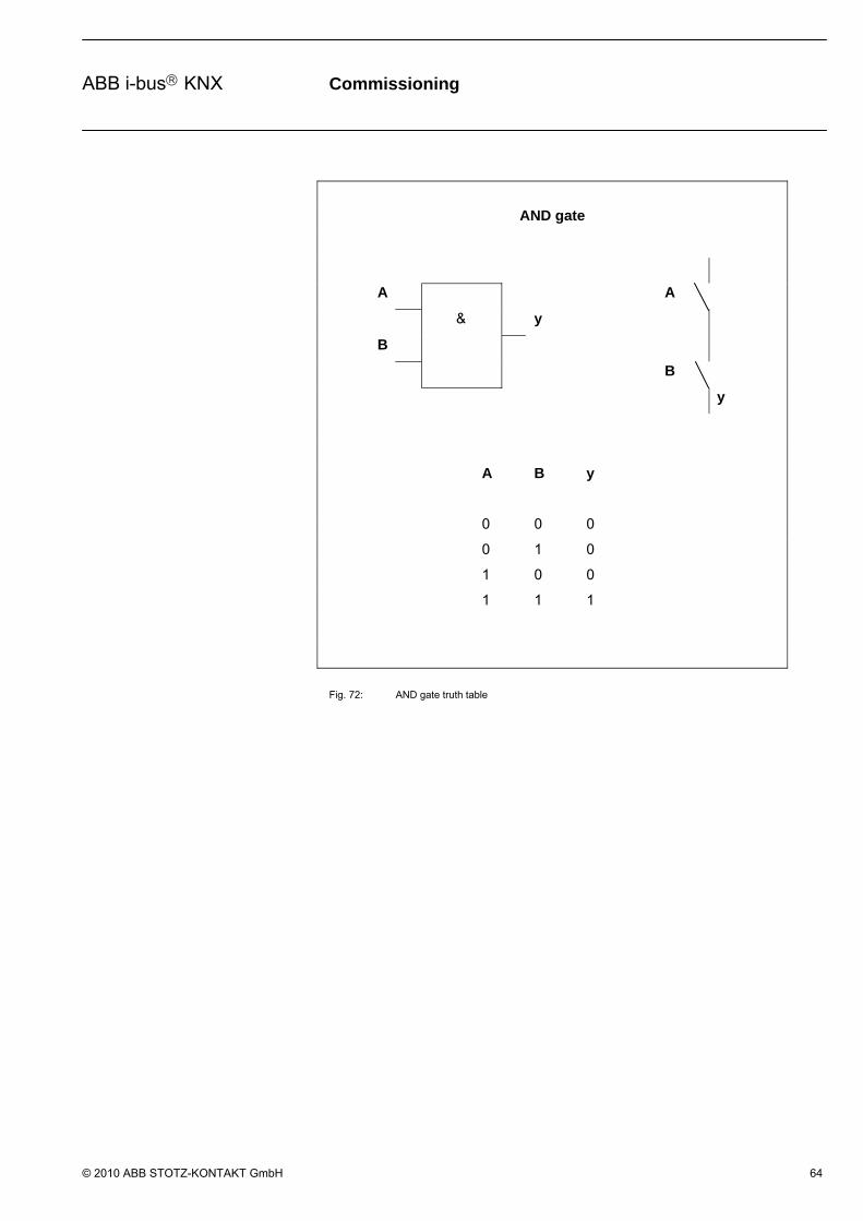
AND gate
A A
& y
B
B
y
A B y
0 0 0
0 1 0
1 0 0
1 1 1
Fig. 72: AND gate truth table

Commissioning
© 2010 ABB STOTZ-KONTAKT GmbH 65
ABB i-bus KNX
3.6.2.1 Creating and deleting inputs
The parameter window Logic element becomes active through the following procedure:
- By a double click on the AND gate.
- Select the element and open the Parameter context menu with the right mouse button.
Fig. 73: Parameter window “AND”“
Name
Options: AND
The name can be chosen as required. A maximum of 36 characters can be used.
Number
Options: 1…50
The number is successive. It can be freely assigned if it is not being used by another element.
Type
Options: AND/ OR/ one hot
The type can be chosen as required.
On the graphic interface the
AND displayed as an &,
the OR as a >=1 and
the one hot as =1.

Commissioning
© 2010 ABB STOTZ-KONTAKT GmbH 66
ABB i-bus KNX
Inputs
In the columns, the successive numbers display of an input is linked or an input is negated (inverted).
The meaning of the individual column is as follows:
No.
Options: 1…8
The number is automatically assigned; it indicates the corresponding number of the input.
Linked
Options: no text/ linked
On this column, you display if an input is linked or not.
Negated
Options: no text/ negated
On this column, you display if an input is negated or not.
New button
Further inputs can be added via the button.
Note: If inputs are added, the previous associations are preserved. A maximum of 8 inputs can be created.
Delete button
An input can be deleted via the button.
Note: The Delete button is only active if the input is not linked. If the number of inputs is reduced, only those inputs that have no associations are deleted.
Commissioning
© 2010 ABB STOTZ-KONTAKT GmbH 67
ABB i-bus KNX
Negate button
An input can be negated via the button. In the graphic user interface, a negated input is signified by a circle.
Note: An output must be linked in order to negate it. The negation of a linked input can be set or deleted directly in the graphical user environment by a double click with the left mouse button on the respective unit.
Negate output
Options activated = ticked not activated = not ticked
The output can be negated by activating the checkbox. In the graphic user interface, a negated output is signified by a circle.
Note: An output must be linked in order to negate it. The negation of a linked output can be set or deleted directly in the graphical user environment by a double click with the left mouse button on the respective output.
OK button
The settings are copied and the parameter window closes via the button.
Cancel button
The function is interrupted and the parameter window closes via the button.

Commissioning
© 2010 ABB STOTZ-KONTAKT GmbH 68
ABB i-bus KNX
3.6.3 OR gate
Fig. 74: OR gate
An OR gate has up to 8 inputs and one output. When newly created, the gates have 2 inputs and one output. The inputs and outputs can be negated (inverted).
The inputs of the OR gate can each be linked with an input object, or an output of another function. The output of a logical element can be linked with an output object or an input of another function. An output of a logical element can thus be linked with several inputs of logical elements.
The inputs are located on the left of the element.
The output is located on the right of the element.
Note: Only 1 bit objects are allowed for the inputs and the output of the OR gate.
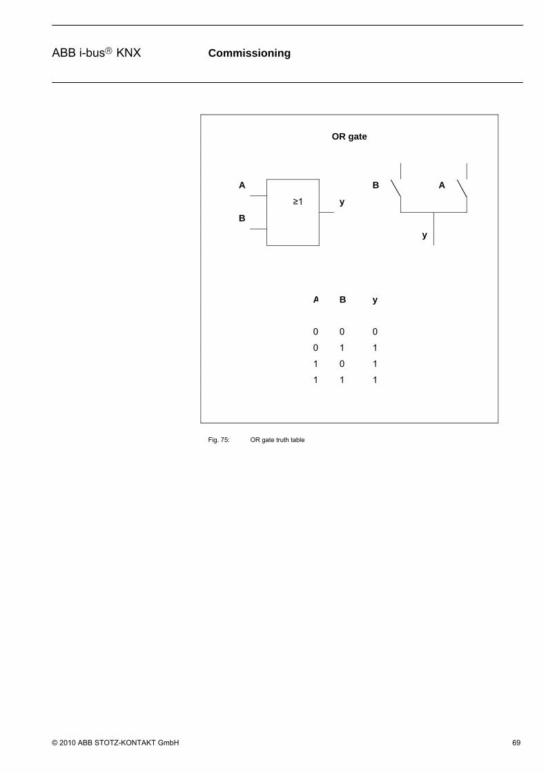
Commissioning
© 2010 ABB STOTZ-KONTAKT GmbH 69
ABB i-bus KNX
OR gate
A B A
≥1 y
B
y
A B y
0 0 0
0 1 1
1 0 1
1 1 1
Fig. 75: OR gate truth table
Commissioning
© 2010 ABB STOTZ-KONTAKT GmbH 70
ABB i-bus KNX
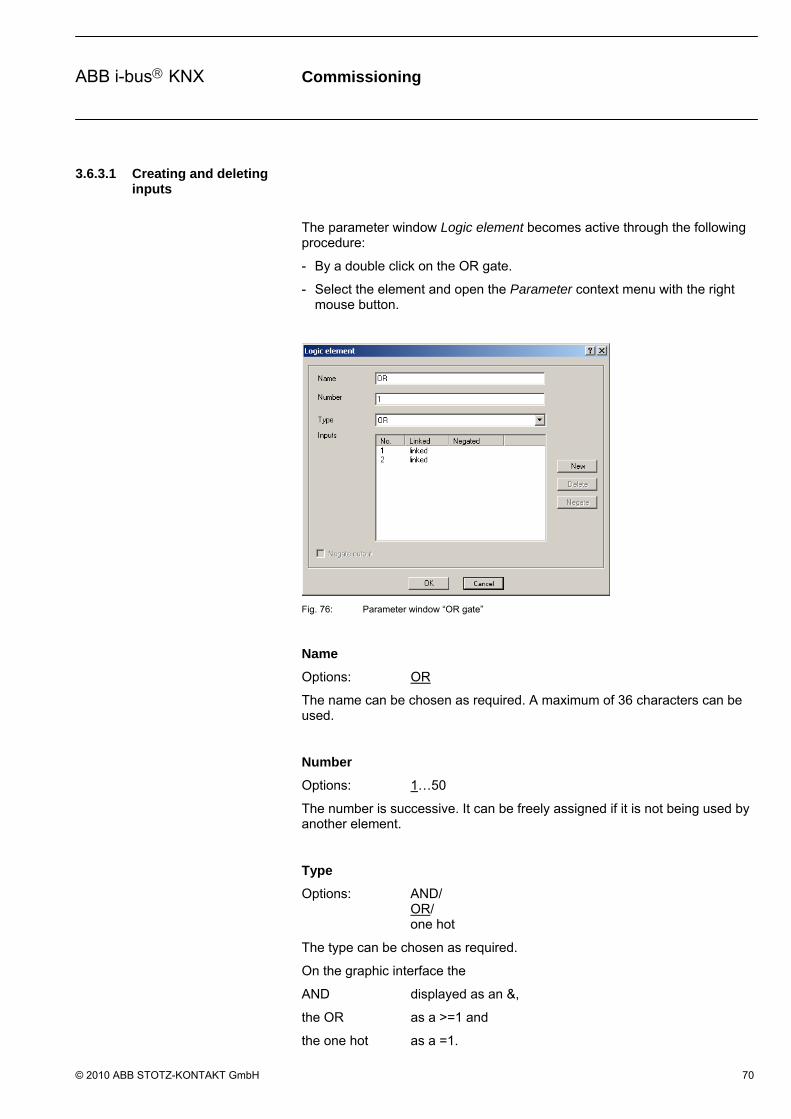
3.6.3.1 Creating and deleting inputs
The parameter window Logic element becomes active through the following procedure:
- By a double click on the OR gate.
- Select the element and open the Parameter context menu with the right mouse button.
Fig. 76: Parameter window “OR gate”
Name
Options: OR
The name can be chosen as required. A maximum of 36 characters can be used.
Number
Options: 1…50
The number is successive. It can be freely assigned if it is not being used by another element.
Type
Options: AND/ OR/ one hot
The type can be chosen as required.
On the graphic interface the
AND displayed as an &,
the OR as a >=1 and
the one hot as a =1.
Commissioning
© 2010 ABB STOTZ-KONTAKT GmbH 71
ABB i-bus KNX
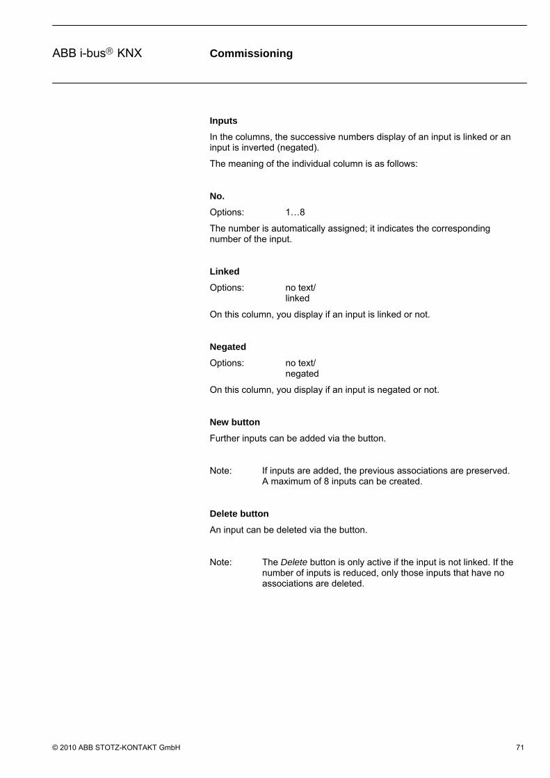
Inputs
In the columns, the successive numbers display of an input is linked or an input is inverted (negated).
The meaning of the individual column is as follows:
No.
Options: 1…8
The number is automatically assigned; it indicates the corresponding number of the input.
Linked
Options: no text/ linked
On this column, you display if an input is linked or not.
Negated
Options: no text/ negated
On this column, you display if an input is negated or not.
New button
Further inputs can be added via the button.
Note: If inputs are added, the previous associations are preserved. A maximum of 8 inputs can be created.
Delete button
An input can be deleted via the button.
Note: The Delete button is only active if the input is not linked. If the number of inputs is reduced, only those inputs that have no associations are deleted.

Commissioning
© 2010 ABB STOTZ-KONTAKT GmbH 72
ABB i-bus KNX
Negate button
An input can be negated via the button. In the graphic user interface, a negated input is signified by a circle.
Note: An output must be linked in order to negate it. The negation of a linked input can be set or deleted directly in the graphical user environment by a double click with the left mouse button on the respective unit.
Negate output
Options activated = ticked not activated = not ticked
The output can be negated by activating the checkbox. In the graphic user interface, a negated output is signified by a circle.
Note: An output must be linked in order to negate it. The negation of a linked output can be set or deleted directly in the graphical user environment by a double click with the left mouse button on the respective output.
OK button
The settings are copied and the parameter window closes via the button.
Cancel button
The function is interrupted and the parameter window closes via the button.

Commissioning
© 2010 ABB STOTZ-KONTAKT GmbH 73
ABB i-bus KNX
3.6.4 One hot gate
Fig. 77: One hot gate
A one hot gate has up to 8 inputs and one output. When newly created, the gate has 2 inputs and one output. The inputs and outputs can be negated (inverted).
The input of the one hot gate can each be linked with an input object, or an output of another function. The output of a logical element is linked with an output object or an input of another function. An output of a logical element can thus be linked with several inputs of logical elements.
The inputs are located on the left of the element.
The output is located on the right of the element.
Note: Only 1 bit objects are allowed for the inputs and the output of the one hot gate.

Commissioning
© 2010 ABB STOTZ-KONTAKT GmbH 74
ABB i-bus KNX
One Hot
A A(0) A(1)
=1 y
B
B(1) B(0)
y
A B y
0 0 0
0 1 1
1 0 1
1 1 0
Fig. 78: One hot – truth table 2 inputs
With 3 inputs or more, the truth table appears as follows:
A B C y
0 0 0 0
0 0 1 1
0 1 0 1
0 1 1 0
1 0 0 1
1 0 1 0
1 1 0 0
1 1 1 0
Fig. 79: One hot – truth table 3 inputs

Commissioning
© 2010 ABB STOTZ-KONTAKT GmbH 75
ABB i-bus KNX
3.6.4.1 Creating and deleting inputs
The parameter window Logic element becomes active through the following procedure:
- By a double click on the one hot gate
- Select the element and open the Parameter context menu with the right mouse button.
Fig. 80: Parameter window One hot gate
Name
Options: one hot
The name can be chosen as required. A maximum of 36 characters can be used.
Number
Options: 1…50
The number is successive. It can be freely assigned if it is not being used by another element.
Type
Options: AND/ OR/ one hot
The type can be chosen as required.
On the graphic interface the
AND displayed as an &,
the OR as a >=1 and
the one hot as a =1.

Commissioning
© 2010 ABB STOTZ-KONTAKT GmbH 76
ABB i-bus KNX
Inputs
In the columns, the successive numbers display of an input is linked or an input is inverted (negated).
The meaning of the individual column is as follows:
No.
Options: 1…8
The number is automatically assigned; it indicates the corresponding number of the input.
Linked
Options: no text/ linked
On this column, you display if an input is linked or not.
Negated
Options: no text/ negated
On this column, you display if an input is negated or not.
New button
Further inputs can be added via the button.
Note: If inputs are added, the previous associations are preserved. A maximum of 8 inputs can be created.
Delete button
An input can be deleted via the button.
Note: The Delete button is only active if the input is not linked. If the number of inputs is reduced, only those inputs that have no associations are deleted.

Commissioning
© 2010 ABB STOTZ-KONTAKT GmbH 77
ABB i-bus KNX
Negate button
An input can be negated via the button. In the graphic user interface, a negated input is signified by a circle.
Note: An output must be linked in order to negate it. The negation of a linked input can be set or deleted directly in the graphical user environment by a double click with the left mouse button on the respective unit.
Negate output
Options activated = ticked not activated = not ticked
The output can be negated by activating the checkbox. In the graphic user interface, a negated output is signified by a circle.
Note: An output must be linked in order to negate it. The negation of a linked output can be set or deleted directly in the graphical user environment by a double click with the left mouse button on the respective output.
OK button
The settings are copied and the parameter window closes via the button.
Cancel button
The function is interrupted and the parameter window closes via the button.
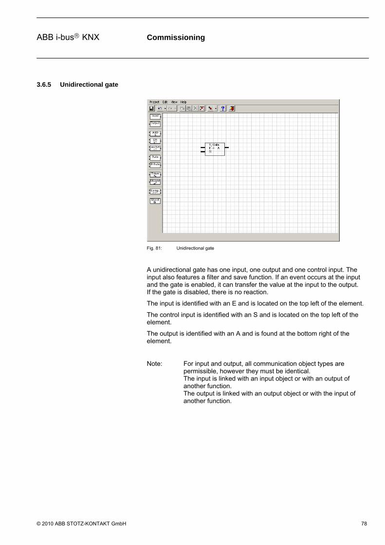
Commissioning
© 2010 ABB STOTZ-KONTAKT GmbH 78
ABB i-bus KNX
3.6.5 Unidirectional gate
Fig. 81: Unidirectional gate
A unidirectional gate has one input, one output and one control input. The input also features a filter and save function. If an event occurs at the input and the gate is enabled, it can transfer the value at the input to the output. If the gate is disabled, there is no reaction.
The input is identified with an E and is located on the top left of the element.
The control input is identified with an S and is located on the top left of the element.
The output is identified with an A and is found at the bottom right of the element.
Note: For input and output, all communication object types are permissible, however they must be identical. The input is linked with an input object or with an output of another function. The output is linked with an output object or with the input of another function.

Commissioning
© 2010 ABB STOTZ-KONTAKT GmbH 79
ABB i-bus KNX
The parameter window Gate becomes active through the following procedure:
- By a double click on the element.
- By opening of the context window with the right mouse button and the Edit parameter... command.
Fig. 82: Parameter window “Bidirectional gate”
Name
Options: Gate
The name can be chosen as required. A maximum of 36 characters can be used.
Number
Options: 1…50
The number is successive. It can be freely assigned if it is not being used by another element.
Control Input
Options: release with IN/ release with OUT
On the graphic user interface, the option release with OUT is identified by a circle. The option release with IN is not marked. The control input is marked with an S.
Note: In order to set the control input it must be connected. The control input can be connected with an input object or the output of another function, only 1 bit objects are permissible.

Commissioning
© 2010 ABB STOTZ-KONTAKT GmbH 80
ABB i-bus KNX
Negate output
Options activated = ticked not activated = not ticked
The output can be negated by activating the checkbox. In the graphic user interface, a negated output is signified by a circle.
Note: An output must be linked in order to negate it. The negation of a linked output can be set or deleted directly in the graphical user environment by a double click with the left mouse button on the respective output.
Filter
Options: none/ passthrough object value 0/ passthrough object value 1
On the graphic user interface, the option none is represented by a dash, the option passthrough object value 0 by F1 and the option passthrough object value 1 by F0.
Option none (-) = no filter function active.
Option passthrough object value 0 = communication objects with value 0 are filtered out.
Option passthrough object value 1 = communication objects with value 1 are filtered out.
Note: The filter can only be activated if the input is assigned to a 1 bit object. The filter function affects the input.
Where is the filter function located in the process chain?
The filter function is situated before the gate, i.e. the input signal initially goes through a filter and then through a gate function.

Commissioning
© 2010 ABB STOTZ-KONTAKT GmbH 81
ABB i-bus KNX
Additional function
Options: none/ Save during blocking phase/ Save value with send trigger
If none is selected, the first received communication object received after the gate is enabled is transferred on to the output of the gate. In the graphic user interface, the option none is identified by a dash.
If Save is selected during the blocking phase, then the communication object value which was last present on the input before enable is transferred onto the output. On the graphic user interface, the option Save during blocking phase is identified by an S.
If you select Save value with send trigger, the gate output sends with every enable command on the control input, even if the gate is already enabled and the communication object value on the input has not changed. On the graphic user interface, the option Save value with send trigger is identified by a T.
Note: In order for this function to be effective, the assigned output must be parameterised accordingly (output sends with every new assignment of a new object value).
OK button
The settings are copied and the parameter window closes via the button.
Cancel button
The function is interrupted and the parameter window closes via the button.

Commissioning
© 2010 ABB STOTZ-KONTAKT GmbH 82
ABB i-bus KNX
3.6.6 Bidirectional gate
Fig. 83: Bidirectional Gate
The bidirectional gate features an input and an output, as well as a control input. No filtering is possible with a bidirectional gate. The enabled gate can transfer a communication object value in both directions. If an input or output object is linked with an input or output of the bidirectional gate, this automatically becomes an input and output.
The input and output are identified with the designation EA and can for found at the top left and top right on the element.
The control input is identified with a C and is located on the top left of the element.
Note: All communication object types are permissible for input and output, however, they must be identical. The input can only be linked to an input/output object. Not to an output or another function. The output can only be linked to an input/output object. Not to an input or another function.
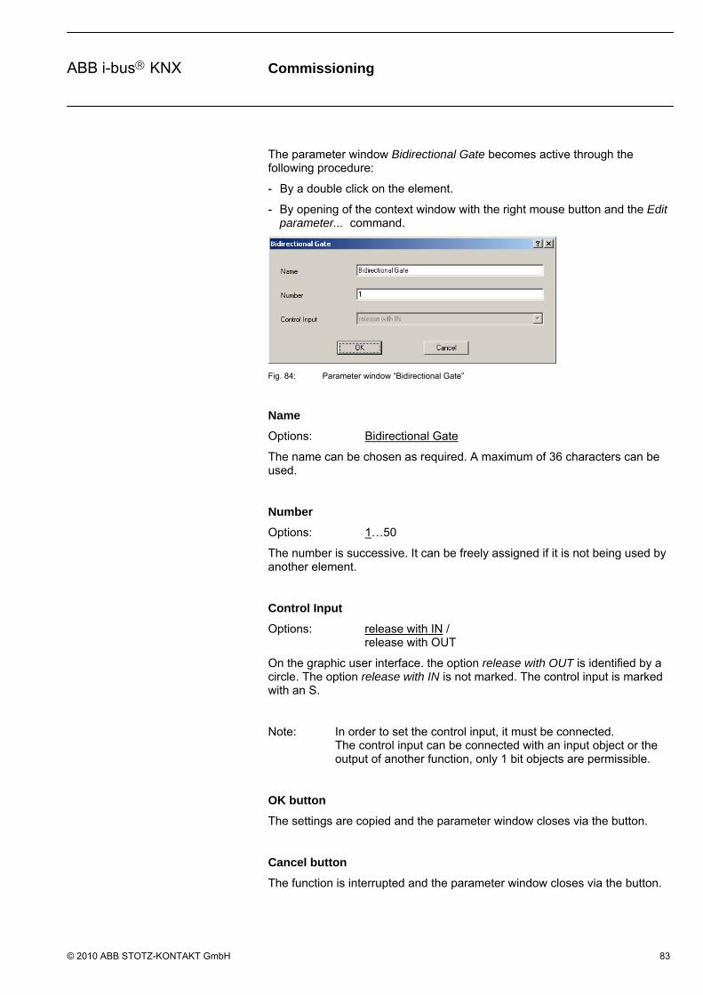
Commissioning
© 2010 ABB STOTZ-KONTAKT GmbH 83
ABB i-bus KNX
The parameter window Bidirectional Gate becomes active through the following procedure:
- By a double click on the element.
- By opening of the context window with the right mouse button and the Edit parameter... command.
Fig. 84: Parameter window “Bidirectional Gate”
Name
Options: Bidirectional Gate
The name can be chosen as required. A maximum of 36 characters can be used.
Number
Options: 1…50
The number is successive. It can be freely assigned if it is not being used by another element.
Control Input
Options: release with IN / release with OUT
On the graphic user interface. the option release with OUT is identified by a circle. The option release with IN is not marked. The control input is marked with an S.
Note: In order to set the control input, it must be connected. The control input can be connected with an input object or the output of another function, only 1 bit objects are permissible.
OK button
The settings are copied and the parameter window closes via the button.
Cancel button
The function is interrupted and the parameter window closes via the button.

Commissioning
© 2010 ABB STOTZ-KONTAKT GmbH 84
ABB i-bus KNX
3.6.7 Timer
Fig. 85: Timer
A timer has an input and an output. The input also has another filter. If an event occurs at the input, the timer can transfer the value at the input to the output with a time delay.
The input of the timer is located on the left of the element.
The output of the timer is located on the right of the element.
Note: The switch on/off telegrams can be re-triggered!

Commissioning
© 2010 ABB STOTZ-KONTAKT GmbH 85
ABB i-bus KNX
What is the initial state?
With bus voltage recovery, all ongoing delays and pulse duration's are stopped. The timer waits for the result on an input.
Note: The timer is connected with an input object or the output of another function; only 1 bit objects are permissible. The output is linked with an output object or with the input of another function.
With bus voltage recovery after a bus voltage failure, the timer immediately assumes the output state, unless a time has been sent in the menu point Initialisation in the menu bar under Edit. In this case, the element will wait for the set time until the output state of the timer is restored.
If, for example, an ON delay is set at the timer and telegrams with the value "1" are sent to the assigned input with a shorter interval than the delay time, then the beginning of the delay is restarted with each new telegram, i.e. the timer operation can never elapse.
If a telegram, which has been filtered out due to the settings arrives at the input of a timer, and if the assigned output has been set so that it sends a telegram each time a new object value is calculated, then the output does not send a telegram in this case. An "effective" filter can thus also be compared with a disabled gate or a timer operation that has not elapsed.

Commissioning
© 2010 ABB STOTZ-KONTAKT GmbH 86
ABB i-bus KNX
The parameter window Timer is opened through the following procedure:
- By a double click on the element.
- By opening of the context window with the right mouse button and the Edit parameter... command.
Fig. 86: Parameter window "Timer"
Name
Options: Timer
The name can be chosen as required. A maximum of 36 characters can be used.
Number
Options: 1…30
The number is successive. It can be freely assigned if it is not being used by another element.
Commissioning
© 2010 ABB STOTZ-KONTAKT GmbH 87
ABB i-bus KNX
Filter
Options: none/ passthrough object value 0/ passthrough object value 1
On the graphic user interface. the option none is represented by a dash, the option passthrough object value 0 by F1 and the option passthrough object value 1 by F0.
Option none (-) = no filter function active.
Option passthrough object value 0 = communication objects with value 0 are filtered out.
Option passthrough object value 1 = communication objects with value 1 are filtered out.
Note: The filter can only be activated if the input is assigned to a 1 bit object. The filter function affects the input.
Where is the filter function located in the process chain?
The filter function is situated before the timer, i.e. the input signals initially go through a filter and then through a time function.
Negated output
Options activated = ticked not activated = not ticked
The output can be negated by activating the checkbox. In the graphic user interface, a negated output is signified by a circle.
Note: An output must be linked in order to negate it. The negation of a linked output can be set or deleted directly in the graphical user environment by a double click with the left mouse button on the respective output.
Delay switch on (te)
Options: Hours 0…18/ Minutes 0…59/ Seconds 0…59
The maximum adjustable on delay is 18:12:15.
On the graphic user interface, the Delay switch on is identified by a te.
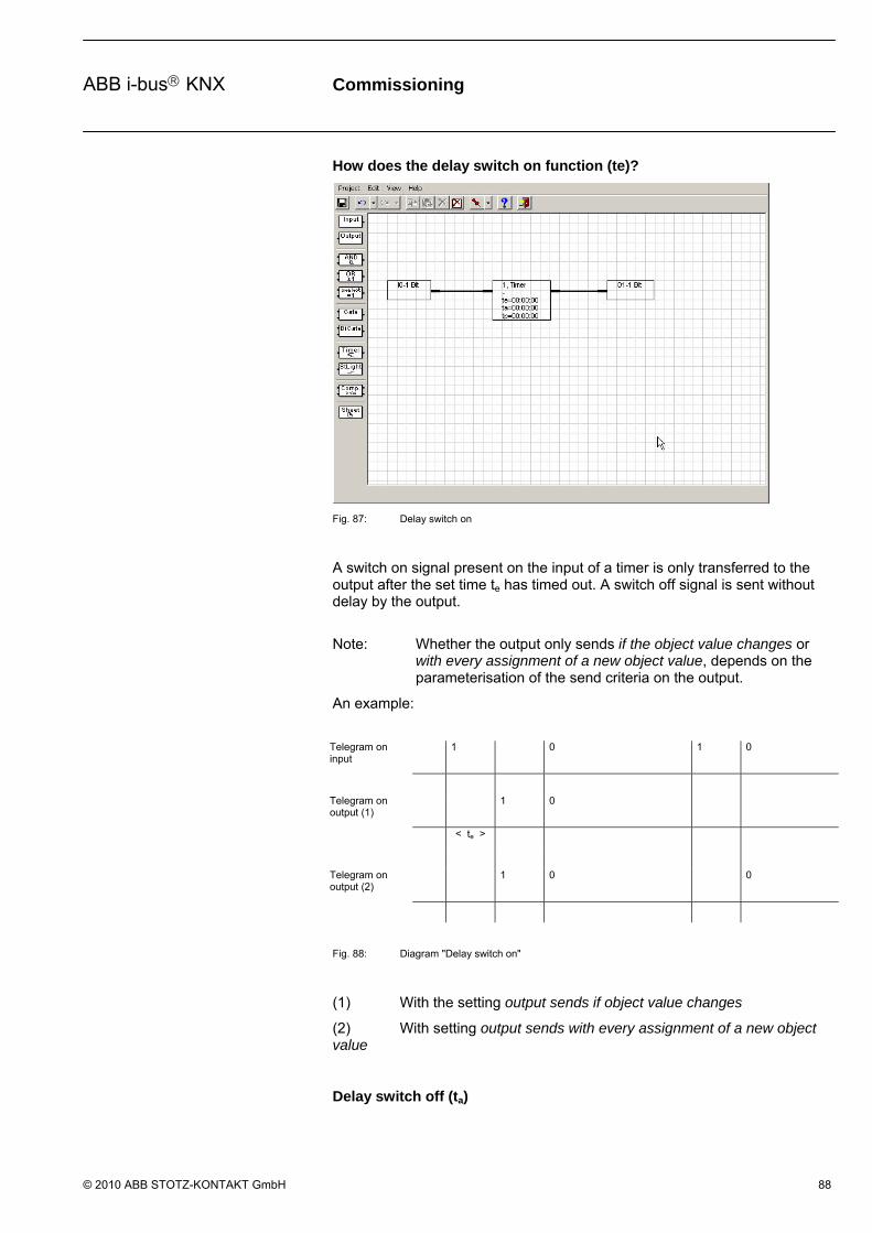
Commissioning
© 2010 ABB STOTZ-KONTAKT GmbH 88
ABB i-bus KNX
How does the delay switch on function (te)?
Fig. 87: Delay switch on
A switch on signal present on the input of a timer is only transferred to the output after the set time te has timed out. A switch off signal is sent without delay by the output.
Note: Whether the output only sends if the object value changes or with every assignment of a new object value, depends on the parameterisation of the send criteria on the output.
An example:
Telegram on input
1 0 1 0
Telegram on output (1)
1 0
< te >
Telegram on output (2)
1 0 0
Fig. 88: Diagram "Delay switch on"
(1) With the setting output sends if object value changes
(2) With setting output sends with every assignment of a new object value
Delay switch off (ta)

Commissioning
© 2010 ABB STOTZ-KONTAKT GmbH 89
ABB i-bus KNX
Options: Hours 0…18/ Minutes 0…59/ Seconds 0…59
The maximum adjustable off delay is 18:12:15.
On the graphic user interface, the Delay switch off is identified by a ta.
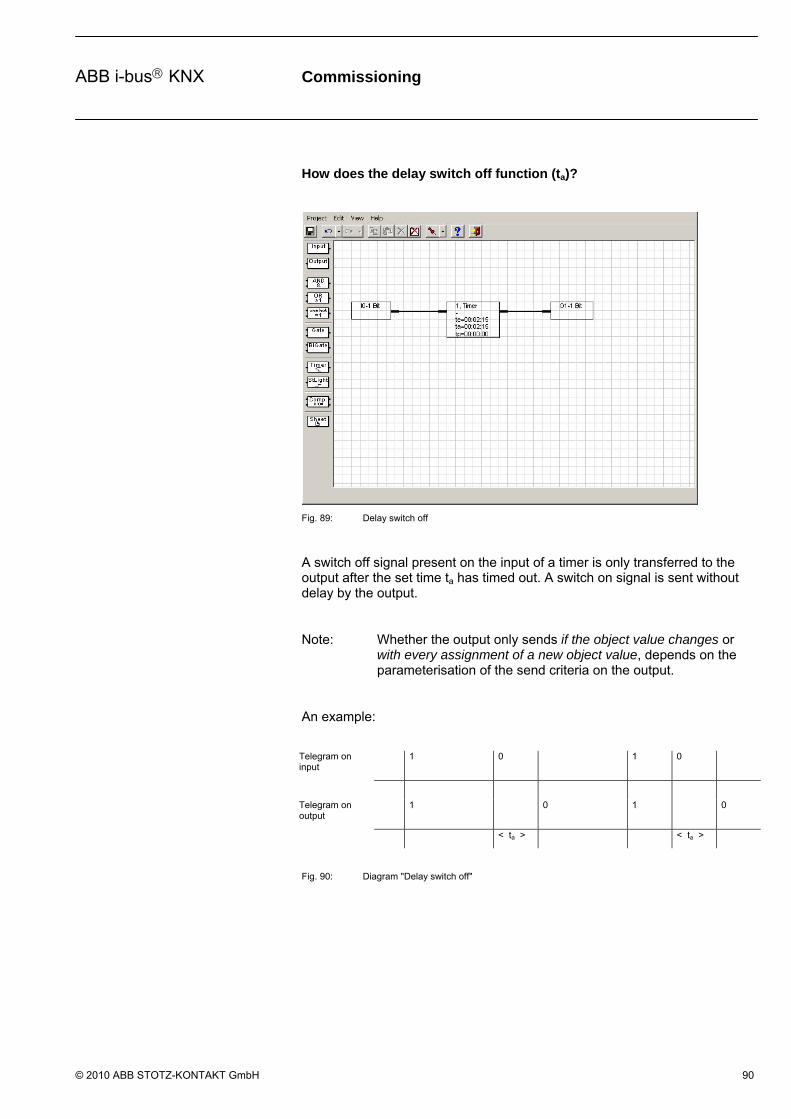
Commissioning
© 2010 ABB STOTZ-KONTAKT GmbH 90
ABB i-bus KNX
How does the delay switch off function (ta)?
Fig. 89: Delay switch off
A switch off signal present on the input of a timer is only transferred to the output after the set time ta has timed out. A switch on signal is sent without delay by the output.
Note: Whether the output only sends if the object value changes or with every assignment of a new object value, depends on the parameterisation of the send criteria on the output.
An example:
Telegram on input
1 0 1 0
Telegram on output
1 0 1 0
< ta > < ta >
Fig. 90: Diagram "Delay switch off"

Commissioning
© 2010 ABB STOTZ-KONTAKT GmbH 91
ABB i-bus KNX
How does the delay switch on and off (te and ta) function?
Fig. 91: Delay switch on and off
A switch on signal present on the input of a timer is only transferred to the output after the set time te has timed out. A switch off signal present on the input of a timer is only transferred to the output after the set time ta has timed out.
Note: Wheterh the output only sends if the object value changes or with every assignment of a new object value, depends on the parameterisation of the send criteria on the output.
An example.
Telegram on input
1 0 1 0
Telegram on output
1 0 0
< ta > < ta >
< te > < te >
Fig. 92: Diagram “Delay switch on and off”
Commissioning
© 2010 ABB STOTZ-KONTAKT GmbH 92
ABB i-bus KNX
Pulse duration (tp)
Options: Hours 0…18/ Minutes 0…59/ Seconds 0…59
The maximum adjustable pulse duration is 18:12:15.
On the graphic user interface, the pulse duration is designated by a tp.
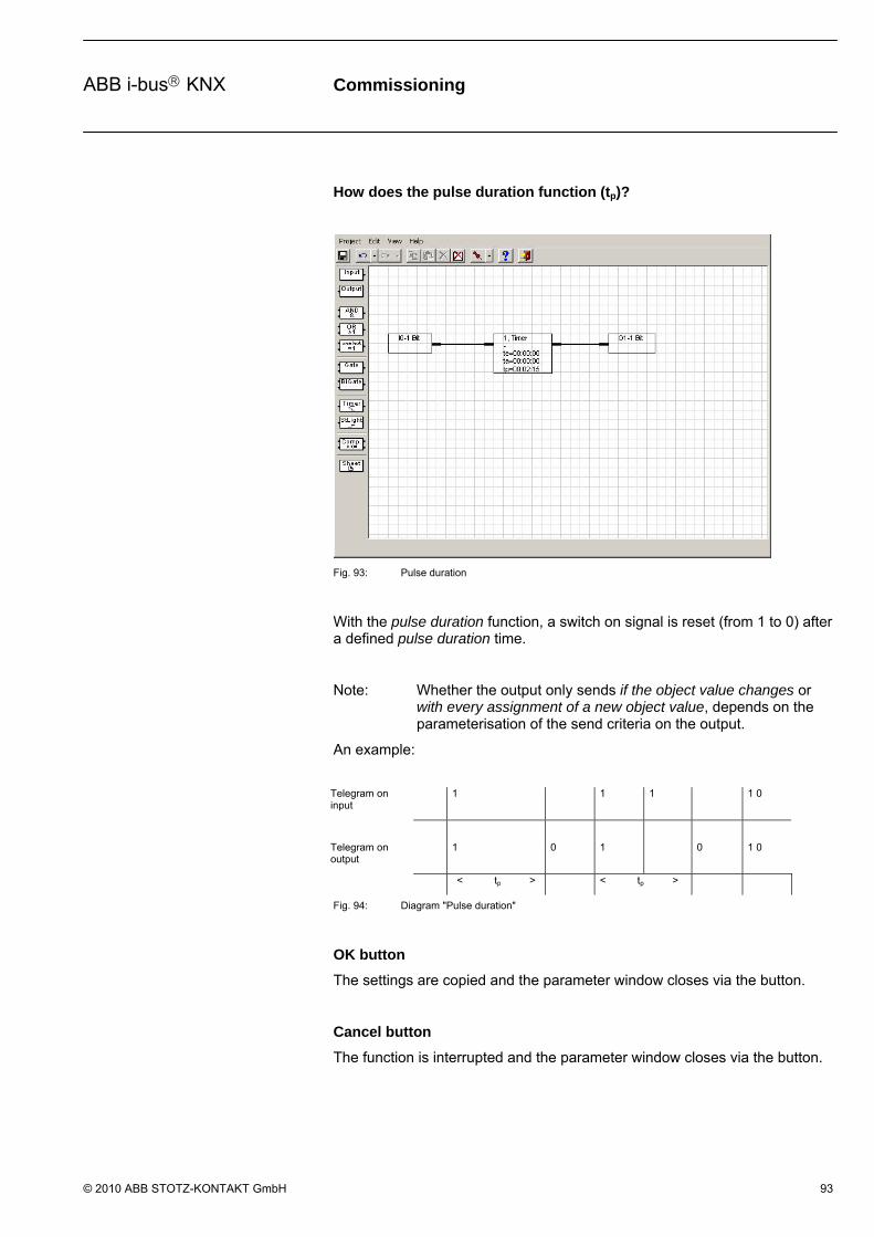
Commissioning
© 2010 ABB STOTZ-KONTAKT GmbH 93
ABB i-bus KNX
How does the pulse duration function (tp)?
Fig. 93: Pulse duration
With the pulse duration function, a switch on signal is reset (from 1 to 0) after a defined pulse duration time.
Note: Whether the output only sends if the object value changes or with every assignment of a new object value, depends on the parameterisation of the send criteria on the output.
An example:
Telegram on input
1 1 1 1 0
Telegram on output
1 0 1 0 1 0
< tp > < tp >
Fig. 94: Diagram "Pulse duration"
OK button
The settings are copied and the parameter window closes via the button.
Cancel button
The function is interrupted and the parameter window closes via the button.

Commissioning
© 2010 ABB STOTZ-KONTAKT GmbH 94
ABB i-bus KNX
How does the switch on delay and pulse duration function (te and tp)?
Fig. 95: Switch on delay and pulse duration
A switch on signal present on the input of a timer is only transferred to the output after the set time te has timed out. After the pulse duration has timed out, the switch on signal is reset (from 1 to 0).
If a new switch on signal is received within the pulse duration time, the set pulse duration remains unchanged and is not extended.
Note: Whether the output only sends if the object value changes or with every assignment of a new object value, depends on the parameterisation of the send criteria on the output.
An example:
Telegram on input
1 1 1 1 1
Telegram on output
1 0 0 1 0
< te > < tp > < te > < tp > < te >
Fig. 96: Diagram "Switch on delay and pulse duration"

Commissioning
© 2010 ABB STOTZ-KONTAKT GmbH 95
ABB i-bus KNX
OK button
The settings are copied and the parameter window closes via the button.
Cancel button
The function is interrupted and the parameter window closes via the button.

Commissioning
© 2010 ABB STOTZ-KONTAKT GmbH 96
ABB i-bus KNX
3.6.8 Staircaselight
Fig. 97: Staircaselight
The Staircaselight function consists of an input which is simultaneously an output.
The input and output of the Staircaselight can be found on the left of the element.
Note: The Staircaselight is linked to an input object, only 1 bit objects are permissible.
In the event of a bus voltage failure, the stairlight function immediately reverts to its initial state i.e. the outputs go to zero signal regardless of the signals applied at the input or the time that has already elapsed.
The behaviour described beforehand is dependent on the linked input and its parameters.

Commissioning
© 2010 ABB STOTZ-KONTAKT GmbH 97
ABB i-bus KNX
How does the Staircaselight function operate?
Fig. 98: Staircase lighting function
With the Staircaselight function, the input signal (which is simultaneously the output signal) is reset after the autoreset time t is reset (e.g. from 1 to 0). If there is a new input signal within the autoreset time, the output signal remains at the existing value and the autoreset time is restarted.
An example:
Telegram on input
1 1 1
Telegram on output
1 0 1 1 0
< t > < t >
< t >
Fig. 99: Diagram "Staircaselight function"
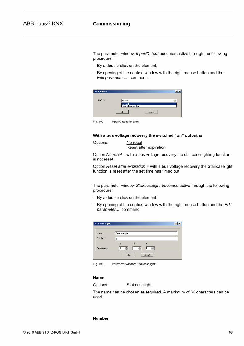
Commissioning
© 2010 ABB STOTZ-KONTAKT GmbH 98
ABB i-bus KNX
The parameter window Input/Output becomes active through the following procedure:
- By a double click on the element,
- By opening of the context window with the right mouse button and the Edit parameter... command.
Fig. 100: Input/Output function
With a bus voltage recovery the switched “on” output is
Options: No reset Reset after expiration
Option No reset = with a bus voltage recovery the staircase lighting function is not reset.
Option Reset after expiration = with a bus voltage recovery the Staircaselight function is reset after the set time has timed out.
The parameter window Staircaselight becomes active through the following procedure:
- By a double click on the element
- By opening of the context window with the right mouse button and the Edit parameter... command.
Fig. 101: Parameter window "Staircaselight"
Name
Options: Staircaselight
The name can be chosen as required. A maximum of 36 characters can be used.
Number

Commissioning
© 2010 ABB STOTZ-KONTAKT GmbH 99
ABB i-bus KNX
Options: 1…30
The number is successive. It can be freely assigned if it is not being used by another element.
Autoreset (t)
Options: Hours 0…18/ Minutes 0…59/ Seconds 0…59
The maximum adjustable autoreset duration is 18:12:15.
On the graphic user interface, the autoreset time is designated by a t.
OK button
The settings are copied and the parameter window closes via the button.
Cancel button
The function is interrupted and the parameter window closes via the button.

Commissioning
© 2010 ABB STOTZ-KONTAKT GmbH 100
ABB i-bus KNX
3.6.9 Comparator
Fig. 102: Comparator
A Comparator consists of two inputs, an output and an overflow output (Err output). It compares two input values with one another after an adjustable comparator operator. If the comparative condition is fulfilled, the output sends a 1, if it is not fulfilled it sends a 0.
Usually input 1 is used for measured values and input 2 for reference values. If the value range is exceeded during a comparison, a fault is indicated on the overflow output (Err output).
The inputs of the comparator are identified with E1 and E2 and are located on the left of the element.
The outputs of the comparator are identified with A and Err and are located on the right of the element.
Note: The two input values must be from the same data type, e.g. 1 byte, 2 byte or 4 byte.
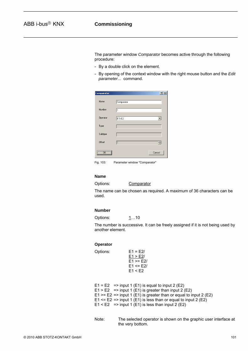
Commissioning
© 2010 ABB STOTZ-KONTAKT GmbH 101
ABB i-bus KNX
The parameter window Comparator becomes active through the following procedure:
- By a double click on the element.
- By opening of the context window with the right mouse button and the Edit parameter... command.
Fig. 103: Parameter window "Comparator"
Name
Options: Comparator
The name can be chosen as required. A maximum of 36 characters can be used.
Number
Options: 1…10
The number is successive. It can be freely assigned if it is not being used by another element.
Operator
Options: E1 = E2/ E1 > E2/ E1 >= E2/ E1 <= E2/ E1 < E2
E1 = E2 => input 1 (E1) is equal to input 2 (E2) E1 > E2 => input 1 (E1) is greater than input 2 (E2) E1 >= E2 => input 1 (E1) is greater than or equal to input 2 (E2) E1 <= E2 => input 1 (E1) is less than or equal to input 2 (E2) E1 < E2 => input 1 (E1) is less than input 2 (E2)
Note: The selected operator is shown on the graphic user interface at the very bottom.

Commissioning
© 2010 ABB STOTZ-KONTAKT GmbH 102
ABB i-bus KNX
Both parameters Type and Subtype remain inactive. Type and subtype in the comparator are oriented according to the input object types.
Type
Options: 1 Byte 2 Byte 4 Byte
The type of input object is displayed in the parameter.
Note: The selected type is shown on the graphic user interface at the very bottom.
Subtype
Options: Floating point Signed Unsigned
The subtype of input object is displayed in the parameter.
The following data types are possible:
1 Byte Unsigned = 0…255 1 Byte Signed = -128…127…
2 Byte Floating point = see table below 2 Byte Unsigned = 0…65.535 2 Byte Signed = -32.768…32.767…
4 Byte Unsigned = 0…4.294.967.295 4 Byte Signed = -2.147.483.648…2.147.483.647…
Offset
Options: 0…255 with 1 Byte Unsigned -128…0…127 with 1 Byte Signed, 0 (see table) with 2 Byte Floating point 0…65.535 with 2 Bytes Unsigned -32.768…0…32.767 with 2 Bytes Signed 0…4.294.967.295 with 4 Bytes Unsigned -2.147.483.648…0… 2.147.483.647 with 4 Bytes Signed
The function Offset functions as soon as an input of the comparator is linked.
For certain applications, e.g. room temperature control, it is necessary to apply an Offset according to the following formula:
Value on E2 + offset = input value

Commissioning
© 2010 ABB STOTZ-KONTAKT GmbH 103
ABB i-bus KNX
If an input is linked to a 2 byte floating point value, the additional parameter power (exp.) appears.
Fig. 104: Parameter window “Comparator - Exponent”
exp
The adjustable Offset depends on the exponent (exp).
Exponent (exp) Offset value
Auto -671,088.64…0.0…670,760.96
0 -20.48…0.00…20.47
1 -40.96…0.00…40.94
2 -81.92…0.00…81.88
3 (temp.) -163.84…0.00…163.76
4 -327.68…0.00…327.52
5 -655.36…0.00…655.04
6 -1,310.72…0.00…1,310.08
7 -2,621.44…0.00…2,620.16
8 -5,242.88…0.00…5,240.32
9 -10,485.76…0.00…10,480.64
10 -20,971.52…0.00…20,961.28
11 -41,943.04…0.00…41,922.56
12 -88,386.08…0.…83,845.12
13 -167,772.16…0.00…167,690.24
14 -335,544.32…0.00…335,380.48
15 -671,088.64…0.0…670,760.96
Table 9: Exponent

Commissioning
© 2010 ABB STOTZ-KONTAKT GmbH 104
ABB i-bus KNX
OK button
The settings are copied and the parameter window closes via the button.
Cancel button
The function is interrupted and the parameter window closes via the button.
Commissioning
© 2010 ABB STOTZ-KONTAKT GmbH 105
ABB i-bus KNX
How does the Err output function?
Err output
If during the calculation of the input value by the Offset a value range is exceeded, a fault message in the form of a 1 is sent by the overflow output (Err output).
For certain application cases, e.g. room temperature control, it is necessary to apply an Offset according to the following formula:
Value on E2 + offset = input value
Note: The offset is added exclusively to the input value E2.
If the calculated input value exceeds the set value range, the Overflow output (Err output) sends an error message.
Example: Max. value range, e.g. 2 byte unsigned (0…65.535) input value on E2 = 65,535 plus an offset of 1 results in the value range being exceeded, i.e. the Err output sends an ON telegram.
Note: Both inputs of the comparator must be linked, otherwise it will not function.

Commissioning
© 2010 ABB STOTZ-KONTAKT GmbH 106
ABB i-bus KNX
3.6.10 Worksheet
Fig. 105: Display of worksheets
More complex parameterisation and a smaller the monitor size can quickly lead to a very unclear view of the graphic parameterisation. Worksheet management is used in order to effectively design this. It describes a part of the graphical parameterisation and is implemented in the form of jump labels.
Note: Worksheets can be applied, edited and deleted.
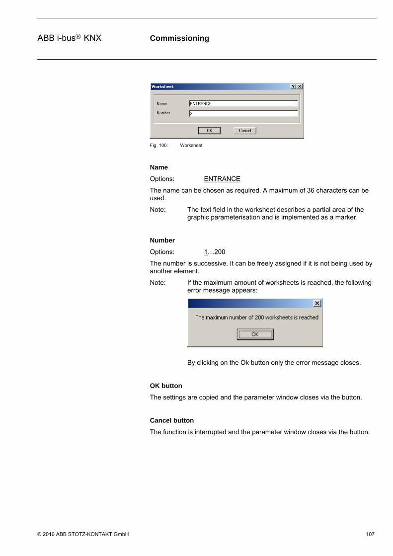
Commissioning
© 2010 ABB STOTZ-KONTAKT GmbH 107
ABB i-bus KNX
Fig. 106: Worksheet
Name
Options: ENTRANCE
The name can be chosen as required. A maximum of 36 characters can be used.
Note: The text field in the worksheet describes a partial area of the graphic parameterisation and is implemented as a marker.
Number
Options: 1…200
The number is successive. It can be freely assigned if it is not being used by another element.
Note: If the maximum amount of worksheets is reached, the following error message appears:
By clicking on the Ok button only the error message closes.
OK button
The settings are copied and the parameter window closes via the button.
Cancel button
The function is interrupted and the parameter window closes via the button.
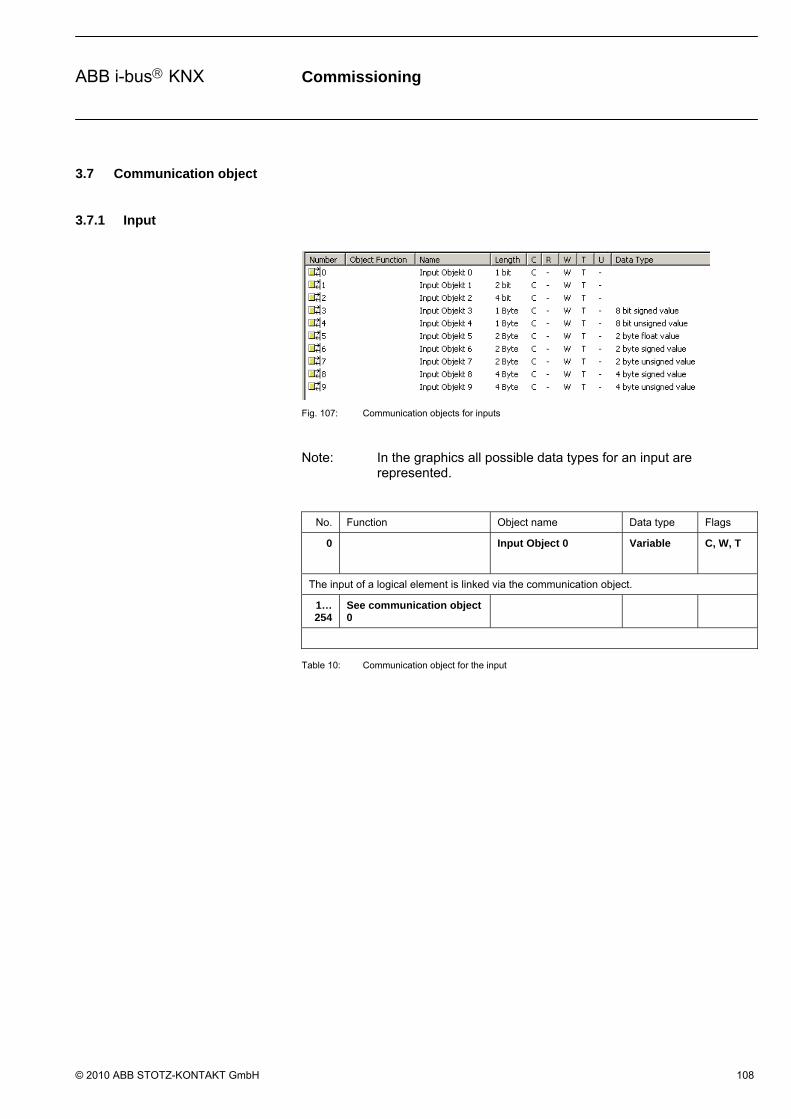
Commissioning
© 2010 ABB STOTZ-KONTAKT GmbH 108
ABB i-bus KNX
3.7 Communication object
3.7.1 Input
Fig. 107: Communication objects for inputs
Note: In the graphics all possible data types for an input are represented.
No. Function Object name Data type Flags
0 Input Object 0 Variable
C, W, T
The input of a logical element is linked via the communication object.
1…254
See communication object 0
Table 10: Communication object for the input
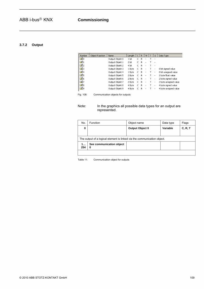
Commissioning
© 2010 ABB STOTZ-KONTAKT GmbH 109
ABB i-bus KNX
3.7.2 Output
Fig. 108: Communication objects for outputs
Note: In the graphics all possible data types for an output are represented.
No. Function Object name Data type Flags
0 Output Object 0 Variable
C, R, T
The output of a logical element is linked via the communication object.
1…254
See communication object 0
Table 11: Communication object for outputs

Commissioning
© 2010 ABB STOTZ-KONTAKT GmbH 110
ABB i-bus KNX
3.7.3 Input and output
Fig. 109: Communication objects for input and output
No. Function Object name Data type Flags
0 Input/Output Object 0 1 bit
C, R, W, T
Via the communication object, the input and output of a logical element, staircase lighting are linked.
1…254
See communication object 0
Table 12: Communication object for input and output
Planning and application
© 2010 ABB STOTZ-KONTAKT GmbH 111
ABB i-bus KNX
4 Planning and application
In this section, you will find some tips for practical use of the Application Unit Logic time.
4.1 Help
Help provides the necessary information for parameterisation of the application program Logic Time 254 EA/2.
Help is accessed as follows:
- Press the Help button in the dialog window,
- In the Worksheet, press the right mouse button to select Help,
- Press F1 on the keyboard or
- Press the Help button in the toolbar.
You can best work with the application program and its help as follows:
First of all, start the ETS3 and open the project which you require. Minimise the ETS3 main window and push it to the top right.
After the start of the application program, minimise the window and move it to the right edge of the screen so that about a third of the screen width remains free. Now call up Help and minimise and position the window that opens in the free area on the left of the monitor.
Now you can see the corresponding help page for every processing step on the left hand side if you access Help to obtain information. You can obtain further explanations about these terms by clicking on the green marked and underlined terms. You can return to the original Help page with Back.

Planning and application
© 2010 ABB STOTZ-KONTAKT GmbH 112
ABB i-bus KNX
4.2 Transient intermediate states (Glitches)
From hard-wired programmed controls it is well known that internal propagation times of the gates can cause the occurrence of transients, i.e. temporary transient states. These so-called glitches do not become apparent as they only last a few milliseconds, and normally all memory devices and outputs have a delay of a few milliseconds.
Transient states can also occur on the ABL/S 2.1. This becomes noticeable, for example, when several telegrams are sent successively from a stable output state on the bus until a stable output state is re-established.
These glitches only become noticeable as the bus device that should react to these telegrams also reacts.
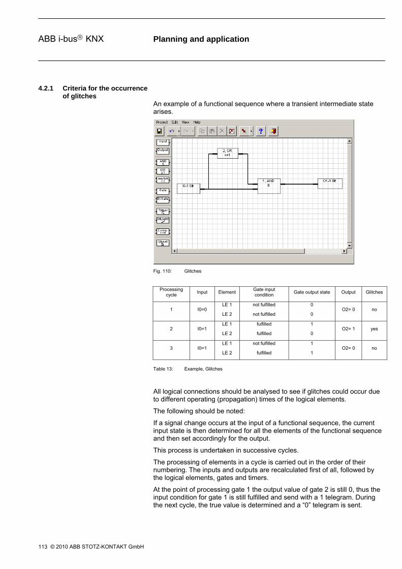
Planning and application
© 2010 ABB STOTZ-KONTAKT GmbH 113
ABB i-bus KNX
4.2.1 Criteria for the occurrence of glitches
An example of a functional sequence where a transient intermediate state arises.
Fig. 110: Glitches
Table 13: Example, Glitches
All logical connections should be analysed to see if glitches could occur due to different operating (propagation) times of the logical elements.
The following should be noted:
If a signal change occurs at the input of a functional sequence, the current input state is then determined for all the elements of the functional sequence and then set accordingly for the output.
This process is undertaken in successive cycles.
The processing of elements in a cycle is carried out in the order of their numbering. The inputs and outputs are recalculated first of all, followed by the logical elements, gates and timers.
At the point of processing gate 1 the output value of gate 2 is still 0, thus the input condition for gate 1 is still fulfilled and send with a 1 telegram. During the next cycle, the true value is determined and a “0” telegram is sent.
Processing cycle
Input Element Gate input condition
Gate output state Output Glitches
1 I0=0 LE 1
LE 2
not fulfilled
not fulfilled
0
0 O2= 0 no
2 I0=1 LE 1
LE 2
fulfilled
fulfilled
1
0 O2= 1 yes
3 I0=1 LE 1
LE 2
not fulfilled
fulfilled
1
1 O2= 0 no
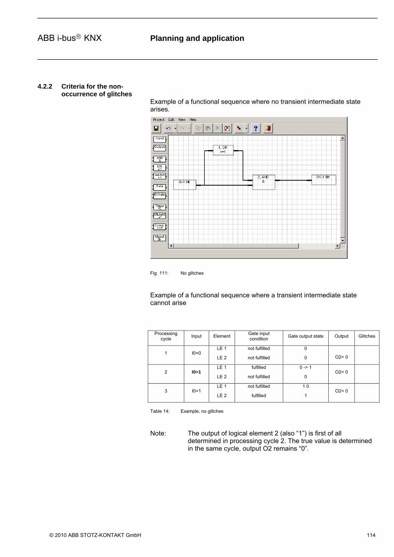
Planning and application
© 2010 ABB STOTZ-KONTAKT GmbH 114
ABB i-bus KNX
4.2.2 Criteria for the non-occurrence of glitches
Example of a functional sequence where no transient intermediate state arises.
Fig. 111: No glitches
Example of a functional sequence where a transient intermediate state cannot arise
Table 14: Example, no glitches
Note: The output of logical element 2 (also “1”) is first of all determined in processing cycle 2. The true value is determined in the same cycle, output O2 remains “0”.
Processing cycle
Input Element Gate input condition
Gate output state Output Glitches
1 I0=0 LE 1
LE 2
not fulfilled
not fulfilled
0
0 O2= 0
2 I0=1 LE 1
LE 2
fulfilled
not fulfilled
0 -> 1
0 O2= 0
3 I0=1 LE 1
LE 2
not fulfilled
fulfilled
1 0
1 O2= 0

Planning and application
© 2010 ABB STOTZ-KONTAKT GmbH 115
ABB i-bus KNX
4.3 Reaction time
The application program Logic Time 254 EA/2 of the application unit ABL/S 2.1, processes the logical functions sequentially, similar to a PLC.
The state of the input and outputs is then determined in one processing cycle. Finally, the elements are processed internally according to the parameters that have been assigned
The processing of elements in a cycle is carried out in the order of their numbering. The logical elements are calculated first of all, followed by the gates and then the timers.
Finally, the newly calculated states are sent.
The timer for a processing cycle – for processing the elements in ascending numerical order – is typically 100 ms.
4.4 Reaction on bus voltage failure
With a bus voltage failure, the Application Unit Logic saves the communication object values of the inputs and outputs for at least one hour. If the bus voltage failure lasts considerably longer than an hour, the stored communication object values are lost.
Safe states after a bus voltage failure can be achieved by the selection of the behaviour after bus recovery parameter setting.
Planning and application
© 2010 ABB STOTZ-KONTAKT GmbH 116
ABB i-bus KNX
4.5 Behaviour after voltage recovery
In order to avoid unwanted operational performance after a bus voltage failure, particularly in larger installations, the installation of an uninterruptible power supply (UPS) should be undertaken for the bus voltage and for the interrogation voltage of the contacts.
4.5.1 Cold start
Start behaviour:
- The inactive waiting period times out. - All RAM data is deleted. - The communication objects are initialised in accordance with the parameters After bus voltage recovery …with data loss and preset value. - If inputs are to be queried, they are queried every second. - All logic functions are processed.
4.5.2 Warm start and bus reset
Start behaviour:
- The inactive waiting period times out. - Gate states and all timer states are deleted. - The communication objects are initialised in accordance with the parameters After bus voltage recovery …without data loss and preset value. - If inputs are to be queried, they are queried every second. - All logic functions are processed.

Appendix
© 2010 ABB STOTZ-KONTAKT GmbH VII
ABB i-bus KNX
Appendix
A.1 Scope of delivery
The Application Unit Logic is supplied with the following parts. Please check the items received using the following list.
– 1 pc. ABL/S 2.1, Application Unit Logic, MDRC
– 1 pc. Installation and operating instructions
– 1 pc. Bus connection terminal (red/black)
Appendix
© 2010 ABB STOTZ-KONTAKT GmbH VIII
ABB i-bus KNX
A.2 Directory of drawings
Fig. 1: ABL/S 2.1 .........................................................................................................................6 Fig. 2: Circuit diagram .................................................................................................................7 Fig. 3: Dimension drawing ...........................................................................................................8 Fig. 4: Import of the application program Logic Time 254 EA Part 1.........................................11 Fig. 5: Import of the application program Logic Time 254 EA Part 2.........................................12 Fig. 6: Import of the application program Logic Time 254 EA Part 3.........................................13 Fig. 7: Import of the application program Logic Time 254 EA Part 4.........................................14 Fig. 8: Import of the application program Logic Time 254 EA Part 5.........................................15 Fig. 9: “Logic Time 254 IO/2” user interface..............................................................................17 Fig. 10: “Title bar” user interface .................................................................................................17 Fig. 11: “Menu bar” user interface ...............................................................................................17 Fig. 12: “Project selection menu” user interface..........................................................................18 Fig. 13: “Edit selection menu” user interface...............................................................................19 Fig. 14: Context menu Copy - Paste ...........................................................................................20 Fig. 15: Context menu Copy - Paste ...........................................................................................21 Fig. 16: User interface “AB/S 1.1 and ABL/S 2.1” .......................................................................21 Fig. 17: User interface “Import from Logic Time 200 EA/1.4” device ..........................................22 Fig. 18: User interface “Import Logic Time 200 EA/1.4 configuration” ........................................22 Fig. 19: User interface “Import from Logic Time 254 EA - successful” ........................................24 Fig. 20: User interface initialization..............................................................................................25 Fig. 21: Behaviour after voltage recovery....................................................................................25 Fig. 22: User interface “View selection menu”.............................................................................26 Fig. 23: User interface “Goto worksheet…”.................................................................................27 Fig. 24: User interface “Dock toolbox” .........................................................................................28 Fig. 25: User interface “Help selection menu” .............................................................................28 Fig. 26: User interface “About…”.................................................................................................28 Fig. 27: User interface “Toolbar”..................................................................................................29 Fig. 28: Save icon........................................................................................................................29 Fig. 29: Undo last action toolbar..................................................................................................29 Fig. 30: Redo last action toolbar..................................................................................................29 Fig. 31: Symbol - Copy (inactive) ................................................................................................30 Fig. 32: Symbol - Copy (active) ...................................................................................................30 Fig. 33: Context menu Copy - Paste ...........................................................................................30 Fig. 34: Symbol - Paste (inactive)................................................................................................30 Fig. 35: Symbol - Paste (active) ..................................................................................................30 Fig. 36: Context menu Copy - Paste ...........................................................................................31 Fig. 37: Delete the selected element or link icon.........................................................................31 Fig. 38: Delete all objects and links icon .....................................................................................31 Fig. 39: Define pin on position of the toolbar icon .......................................................................32 Fig. 40: Display help themes icon................................................................................................32 Fig. 41: Exit icon ..........................................................................................................................32 Fig. 42: Toolbar ...........................................................................................................................34 Fig. 43: Input................................................................................................................................34 Fig. 44: Output.............................................................................................................................35 Fig. 45: AND gate ........................................................................................................................35 Fig. 46: OR gate ..........................................................................................................................35 Fig. 47: One hot gate...................................................................................................................35 Fig. 48: Gate................................................................................................................................36 Fig. 49: Bidirectional gate ............................................................................................................36 Fig. 50: Timer ..............................................................................................................................36 Fig. 51: Staircase light .................................................................................................................36 Fig. 52: Comparator.....................................................................................................................37 Fig. 53: Worksheet ......................................................................................................................37 Fig. 54: Assigning new elements.................................................................................................38 Fig. 55: Symbol - Copy (active) ...................................................................................................39 Fig. 56: Context menu Copy - Paste ...........................................................................................39 Fig. 57: Symbol - Paste (active) ..................................................................................................40 Fig. 58: Context menu Copy - Paste ...........................................................................................40 Fig. 59: Linking functions.............................................................................................................42 Fig. 60: Parameter window “Link to interface” .............................................................................43 Fig. 61: Displaying links...............................................................................................................44 Fig. 62: Input................................................................................................................................45 Fig. 63: Parameter window “Input” ..............................................................................................46 Fig. 64: Parameter window “Input - Exponent” ............................................................................48 Fig. 65: Parameter window “Input - Exponent” ............................................................................50 Fig. 66: Output.............................................................................................................................52 Fig. 67: Parameter window “Output”............................................................................................53 Fig. 68: Feedback example .........................................................................................................56 Fig. 69: Parameter window “Edit Object”.....................................................................................57 Fig. 70: Parameter window “Link To Group Address” .................................................................61
Appendix
© 2010 ABB STOTZ-KONTAKT GmbH IX
ABB i-bus KNX
Fig. 71: AND gate ........................................................................................................................63 Fig. 72: AND gate truth table .......................................................................................................64 Fig. 73: Parameter window “AND”“..............................................................................................65 Fig. 74: OR gate ..........................................................................................................................68 Fig. 75: OR gate truth table .........................................................................................................69 Fig. 76: Parameter window “OR gate” .........................................................................................70 Fig. 77: One hot gate...................................................................................................................73 Fig. 78: One hot – truth table 2 inputs .........................................................................................74 Fig. 79: One hot – truth table 3 inputs .........................................................................................74 Fig. 80: Parameter window One hot gate ....................................................................................75 Fig. 81: Unidirectional gate..........................................................................................................78 Fig. 82: Parameter window “Bidirectional gate”...........................................................................79 Fig. 83: Bidirectional Gate ...........................................................................................................82 Fig. 84: Parameter window “Bidirectional Gate” ..........................................................................83 Fig. 85: Timer ..............................................................................................................................84 Fig. 86: Parameter window "Timer" .............................................................................................86 Fig. 87: Delay switch on ..............................................................................................................88 Fig. 88: Diagram "Delay switch on" .............................................................................................88 Fig. 89: Delay switch off ..............................................................................................................90 Fig. 90: Diagram "Delay switch off" .............................................................................................90 Fig. 91: Delay switch on and off ..................................................................................................91 Fig. 92: Diagram “Delay switch on and off” .................................................................................91 Fig. 93: Pulse duration.................................................................................................................93 Fig. 94: Diagram "Pulse duration" ...............................................................................................93 Fig. 95: Switch on delay and pulse duration................................................................................94 Fig. 96: Diagram "Switch on delay and pulse duration"...............................................................94 Fig. 97: Staircaselight ..................................................................................................................96 Fig. 98: Staircase lighting function...............................................................................................97 Fig. 99: Diagram "Staircaselight function" ...................................................................................97 Fig. 100: Input/Output function ......................................................................................................98 Fig. 101: Parameter window "Staircaselight".................................................................................98 Fig. 102: Comparator...................................................................................................................100 Fig. 103: Parameter window "Comparator" .................................................................................101 Fig. 104: Parameter window “Comparator - Exponent” ...............................................................103 Fig. 105: Display of worksheets...................................................................................................106 Fig. 106: Worksheet ....................................................................................................................107 Fig. 107: Communication objects for inputs ................................................................................108 Fig. 108: Communication objects for outputs ..............................................................................109 Fig. 109: Communication objects for input and output ................................................................110 Fig. 110: Glitches.........................................................................................................................113 Fig. 111: No glitches....................................................................................................................114
Appendix
© 2010 ABB STOTZ-KONTAKT GmbH X
ABB i-bus KNX
A.3 Directory of tables
Table 1: Technical data ..................................................................................................................6 Table 2: Application program..........................................................................................................7 Table 3: Functions of the application program .............................................................................10 Table 4: Exponent ........................................................................................................................48 Table 5: Exponent ........................................................................................................................50 Table 6: Exponent ........................................................................................................................54 Table 7: Communication flags ......................................................................................................58 Table 8: Standard settings of the flags .........................................................................................60 Table 9: Exponent ......................................................................................................................103 Table 10: Communication object for the input ..............................................................................108 Table 11: Communication object for outputs ................................................................................109 Table 12: Communication object for input and output ..................................................................110 Table 13: Example, Glitches.........................................................................................................113 Table 14: Example, no glitches ....................................................................................................114 Table 15: Ordering details Application Unit Logic, MDRC............................................................. XII
Appendix
© 2010 ABB STOTZ-KONTAKT GmbH XI
ABB i-bus KNX
A.4 Index
Additional function, 81 AND, 5, 10, 63, 64, 65, 70, 75 AND gate, 35, 63 Assignment of the physical address, 5, 6, 9 Bus voltage, 6, 8 Cleaning, 9 Cold start, 49 Commissioning requirements, 8 Communication, 58, 60 Comparators, 4, 5, 6, 10, 37, 101, 102, 103, 104 Control input, 36, 78, 79, 81, 82, 83 Copy, 20, 21, 30, 31, 39, 40 Copying, 39 Current consumption, bus, 6 Download behaviour, 9 Edit, 17, 19, 22, 30, 31, 57, 85 Exit, 18, 32, 33 Feedback, 56 Filter function, 80, 87 Flag, 58 Flags, 58, 60, 109, 110, 111 Gate, 36, 55, 60, 78, 79, 81, 82, 83, 85 Gates, 4, 5, 10, 114, 116 Glitches, 113, 114, 115 Grid, 26, 38 Group address, 9, 59, 60, 61 Help, 17, 28, 32, 33, 38, 41, 112 Hotkey, 18, 19, 20, 27, 28, 30, 32, 33, 39, 40 Import, 11, 12, 13, 14, 15, 21, 22, 23, 24 Initialisation, 25, 85 Input, 34, 35, 36, 45, 46, 48, 50, 55, 56, 60, 63, 66,
67, 68, 71, 72, 73, 76, 77, 78, 80, 81, 82, 84, 85, 87, 88, 90, 91, 93, 95, 97, 98, 101, 102, 103, 104, 109, 114, 115
Intermediate states, 113 Leakage loss, bus, 6 Linking, 42, 43, 44
Maintenance, 9 Menu bar, 17, 85 OFF delay, 5, 6, 10, 89, 90, 91 ON delay, 5, 85, 87, 88 One hot, 5, 10, 35, 65, 70, 73, 74, 75 OR, 5, 10, 65, 68, 69, 70, 75 OR gate, 35, 68 Output, 35, 36, 37, 43, 52, 53, 55, 56, 60, 63, 67, 68,
72, 73, 77, 78, 79, 80, 81, 82, 83, 84, 85, 87, 88, 90, 91, 93, 95, 97, 98, 101, 106, 110, 111, 114, 115
Page setup, 18 Paste, 20, 21, 30, 31, 39, 40 Power supply, 6 Print, 18 Print preview, 18 priority, 58 Programming, 4, 7, 9, 10 Project, 17, 18, 21, 112 Pulse duration, 5, 6, 10, 85, 92, 93, 95 Read, 58, 60 Redo, 19, 33 Refresh, 27, 33 Save, 18, 29, 32, 33, 81 Staircase lighting, 36, 60, 97, 98, 100 Staircase lighting function, 5 Supplied state, 9 Timer, 36, 55, 84, 85, 86 Timers, 4, 5, 6, 10, 85, 114, 116 Title bar, 17 Toolbar, 20, 28, 29, 32, 34, 38, 112 Transmit, 58, 60 Undo, 19, 33 Update, 58, 60 View, 17, 26, 38 Worksheet, 10, 27, 34, 37, 38, 41, 43, 107, 108, 112 Write, 58, 60

Appendix
© 2010 ABB STOTZ-KONTAKT GmbH XII
ABB i-bus KNX
A.5 Ordering information
Short description Designation Order No. bbn 40 16779 EAN
Price group
Unit weight 1 pc. [kg]
Pack unit [Pcs]
ABL/S 2.1 Application Unit Logic, MDRC 2CDG 110 072 R0011 652 64 3 26 0.1 1
Table 15: Ordering details Application Unit Logic, MDRC
Appendix
© 2010 ABB STOTZ-KONTAKT GmbH XIII
ABB i-bus KNX
A.6 Notes

Appendix
© 2010 ABB STOTZ-KONTAKT GmbH XIV
ABB i-bus KNX

Contact
Note: We reserve the right to make technical changes or modify the contents of this document without prior notice. With regard to purchase orders, the agreed particulars shall prevail. ABB AG does not accept any responsibility whatsoever for potential errors or possible lack of information in this document. We reserve all rights in this document and in the subject matter and illustrations contained therein. Any reproduction, disclosure to third parties or utilization of its contents - in whole or in parts - is forbidden without prior written consent of ABB AG. Copyright© 2010 ABB All rights reserved
Ord
er N
um
ber
2CD
C 5
09 0
30
D02
04 (
08/1
0)
www.abb.com/knx