abaqus/cae heat transfer tutorial -...
TRANSCRIPT
ME 455/555 Intro to Finite Element Analysis Fall ‘16 Abaqus/CAE Heat Transfer Tutorial
©2016 Hormoz Zareh 1 Portland State University, Mechanical Engineering
Abaqus/CAEHeatTransferTutorial
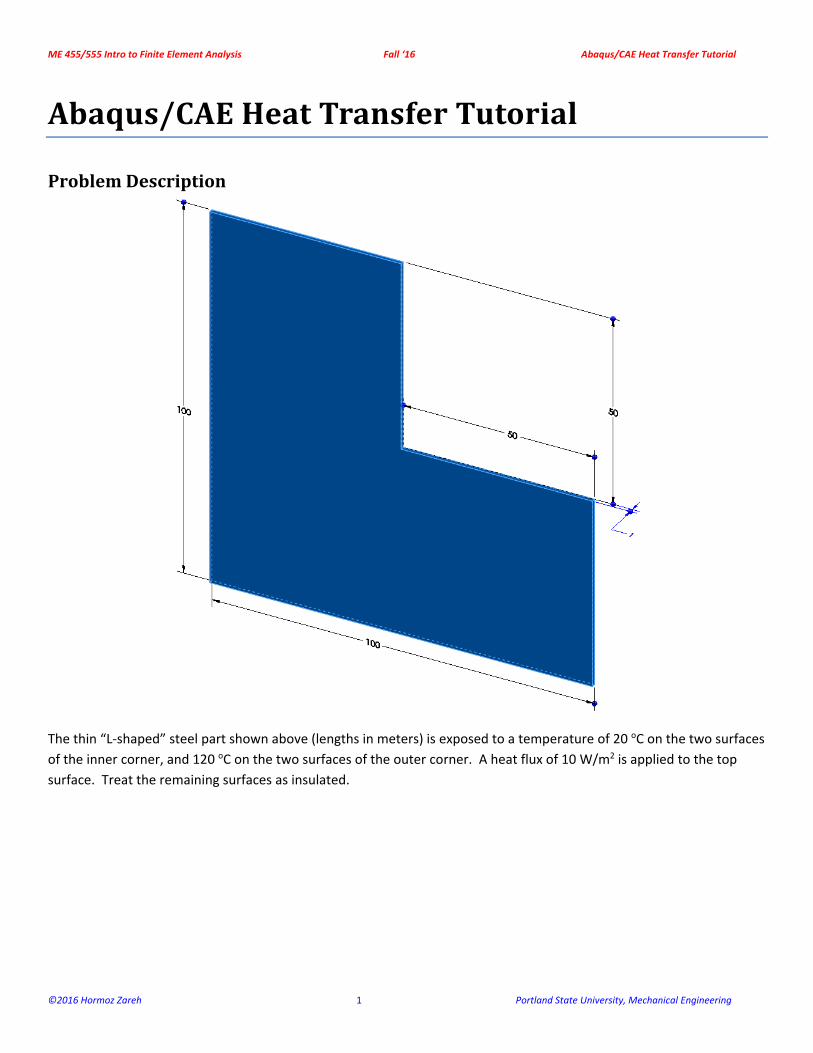
ProblemDescription
The thin “L‐shaped” steel part shown above (lengths in meters) is exposed to a temperature of 20 oC on the two surfaces
of the inner corner, and 120 oC on the two surfaces of the outer corner. A heat flux of 10 W/m2 is applied to the top
surface. Treat the remaining surfaces as insulated.
ME 455/555 Intro to Finite Element Analysis Fall ‘16 Abaqus/CAE Heat Transfer Tutorial
©2016 Hormoz Zareh 2 Portland State University, Mechanical Engineering
AnalysisSteps1. Start Abaqus and choose to create a new model database
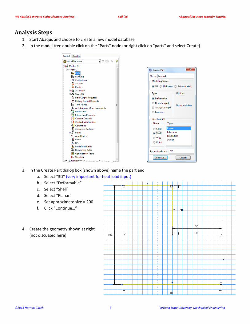
2. In the model tree double click on the “Parts” node (or right click on “parts” and select Create)
3. In the Create Part dialog box (shown above) name the part and
a. Select “3D” (very important for heat load input)
b. Select “Deformable”
c. Select “Shell”
d. Select “Planar”
e. Set approximate size = 200
f. Click “Continue…”
4. Create the geometry shown at right
(not discussed here)
ME 455/555 Intro to Finite Element Analysis Fall ‘16 Abaqus/CAE Heat Transfer Tutorial
©2016 Hormoz Zareh 3 Portland State University, Mechanical Engineering
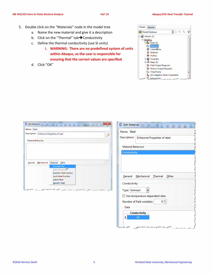
5. Double click on the “Materials” node in the model tree
a. Name the new material and give it a description
b. Click on the “Thermal” tabConductivity
c. Define the thermal conductivity (use SI units)
i. WARNING: There are no predefined system of units
within Abaqus, so the user is responsible for
ensuring that the correct values are specified
d. Click “OK”
ME 455/555 Intro to Finite Element Analysis Fall ‘16 Abaqus/CAE Heat Transfer Tutorial
©2016 Hormoz Zareh 4 Portland State University, Mechanical Engineering
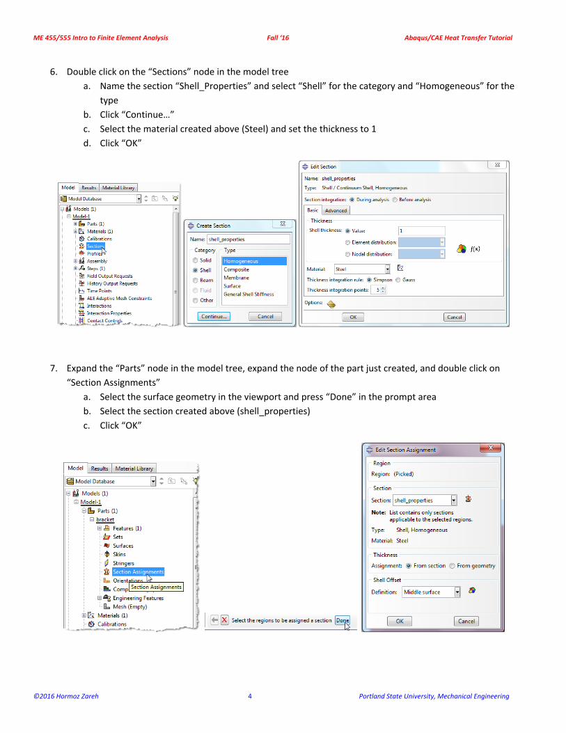
6. Double click on the “Sections” node in the model tree
a. Name the section “Shell_Properties” and select “Shell” for the category and “Homogeneous” for the
type
b. Click “Continue…”
c. Select the material created above (Steel) and set the thickness to 1
d. Click “OK”
7. Expand the “Parts” node in the model tree, expand the node of the part just created, and double click on
“Section Assignments”
a. Select the surface geometry in the viewport and press “Done” in the prompt area
b. Select the section created above (shell_properties)
c. Click “OK”
ME 455/555 Intro to Finite Element Analysis Fall ‘16 Abaqus/CAE Heat Transfer Tutorial
©2016 Hormoz Zareh 5 Portland State University, Mechanical Engineering
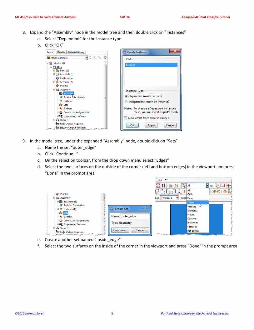
8. Expand the “Assembly” node in the model tree and then double click on “Instances”
a. Select “Dependent” for the instance type
b. Click “OK”
9. In the model tree, under the expanded “Assembly” node, double click on “Sets”
a. Name the set “outer_edge”
b. Click “Continue…”
c. On the selection toolbar, from the drop down menu select “Edges”
d. Select the two surfaces on the outside of the corner (left and bottom edges) in the viewport and press
“Done” in the prompt area
e. Create another set named “inside_edge”
f. Select the two surfaces on the inside of the corner in the viewport and press “Done” in the prompt area
ME 455/555 Intro to Finite Element Analysis Fall ‘16 Abaqus/CAE Heat Transfer Tutorial
©2016 Hormoz Zareh 6 Portland State University, Mechanical Engineering
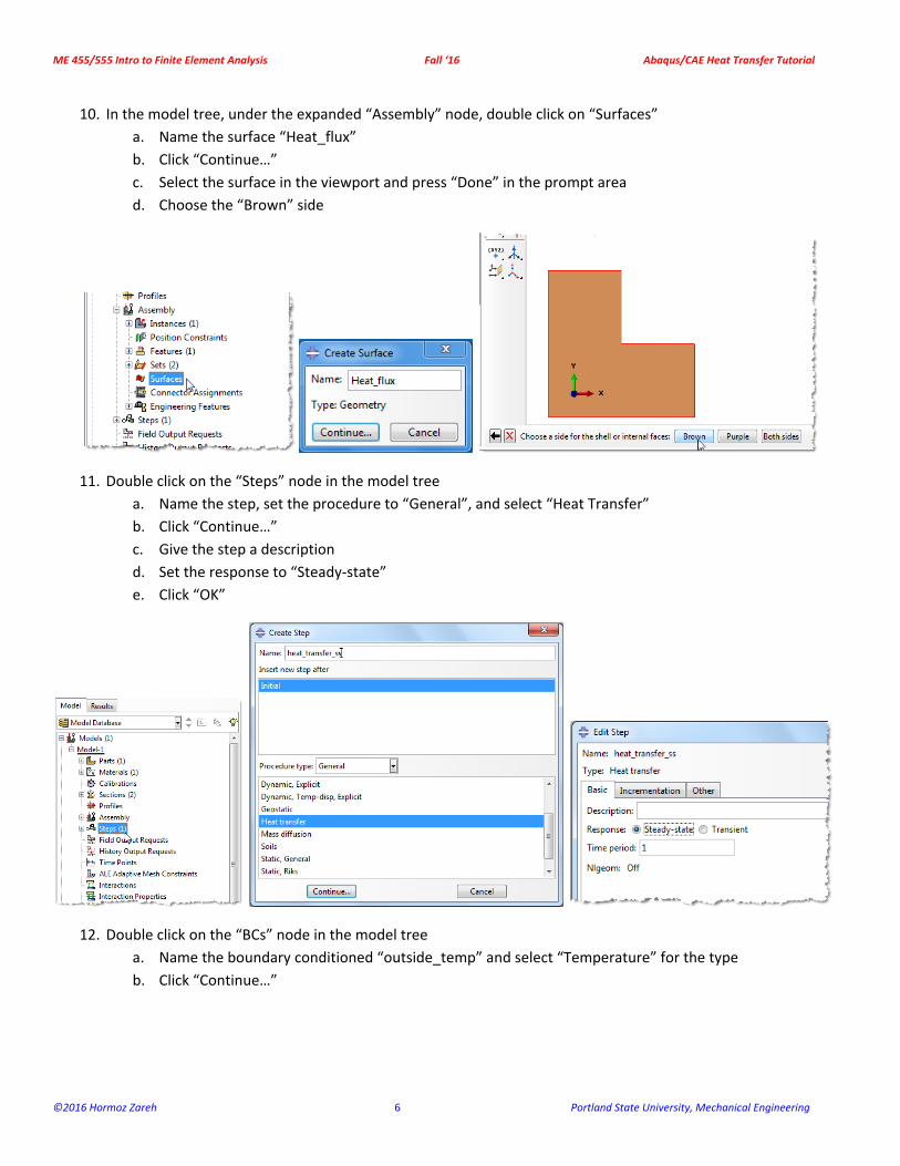
10. In the model tree, under the expanded “Assembly” node, double click on “Surfaces”
a. Name the surface “Heat_flux”
b. Click “Continue…”
c. Select the surface in the viewport and press “Done” in the prompt area
d. Choose the “Brown” side
11. Double click on the “Steps” node in the model tree
a. Name the step, set the procedure to “General”, and select “Heat Transfer”
b. Click “Continue…”
c. Give the step a description
d. Set the response to “Steady‐state”
e. Click “OK”
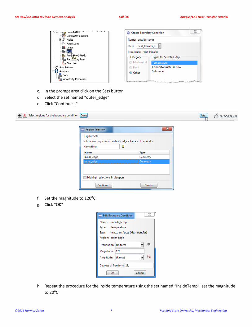
12. Double click on the “BCs” node in the model tree
a. Name the boundary conditioned “outside_temp” and select “Temperature” for the type
b. Click “Continue…”
ME 455/555 Intro to Finite Element Analysis Fall ‘16 Abaqus/CAE Heat Transfer Tutorial
©2016 Hormoz Zareh 7 Portland State University, Mechanical Engineering
c. In the prompt area click on the Sets button
d. Select the set named “outer_edge”
e. Click “Continue…”
f. Set the magnitude to 120⁰C
g. Click “OK”
h. Repeat the procedure for the inside temperature using the set named “InsideTemp”, set the magnitude
to 20⁰C
ME 455/555 Intro to Finite Element Analysis Fall ‘16 Abaqus/CAE Heat Transfer Tutorial
©2016 Hormoz Zareh 8 Portland State University, Mechanical Engineering
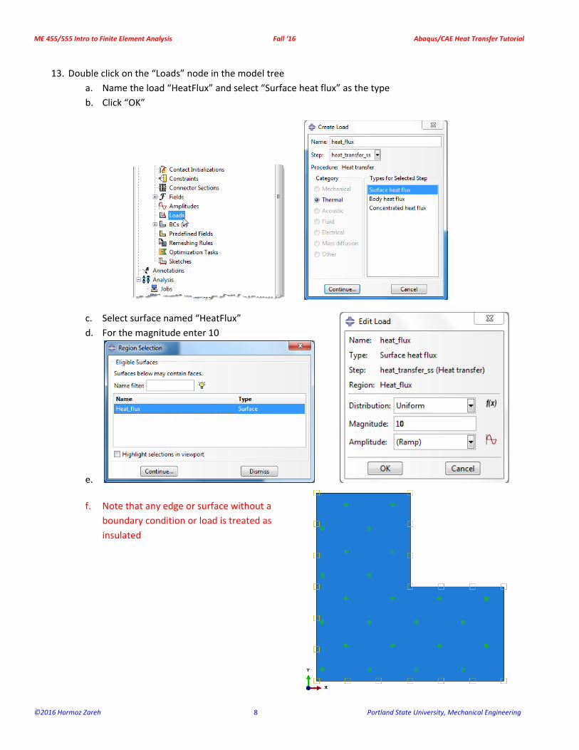
13. Double click on the “Loads” node in the model tree
a. Name the load “HeatFlux” and select “Surface heat flux” as the type
b. Click “OK”
c. Select surface named “HeatFlux”
d. For the magnitude enter 10
e.
f. Note that any edge or surface without a
boundary condition or load is treated as
insulated
ME 455/555 Intro to Finite Element Analysis Fall ‘16 Abaqus/CAE Heat Transfer Tutorial
©2016 Hormoz Zareh 9 Portland State University, Mechanical Engineering
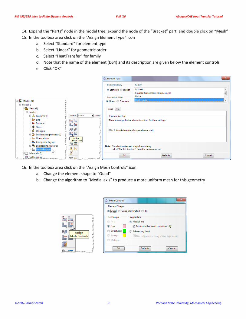
14. Expand the “Parts” node in the model tree, expand the node of the “Bracket” part, and double click on “Mesh”
15. In the toolbox area click on the “Assign Element Type” icon
a. Select “Standard” for element type
b. Select “Linear” for geometric order
c. Select “HeatTransfer” for family
d. Note that the name of the element (DS4) and its description are given below the element controls
e. Click “OK”
16. In the toolbox area click on the “Assign Mesh Controls” icon
a. Change the element shape to “Quad”
b. Change the algorithm to “Medial axis” to produce a more uniform mesh for this geometry
ME 455/555 Intro to Finite Element Analysis Fall ‘16 Abaqus/CAE Heat Transfer Tutorial
©2016 Hormoz Zareh 10 Portland State University, Mechanical Engineering
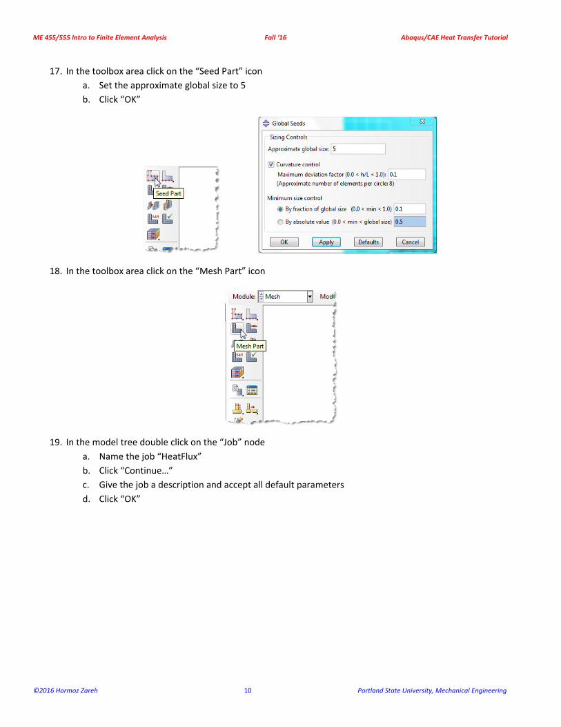
17. In the toolbox area click on the “Seed Part” icon
a. Set the approximate global size to 5
b. Click “OK”
18. In the toolbox area click on the “Mesh Part” icon
19. In the model tree double click on the “Job” node
a. Name the job “HeatFlux”
b. Click “Continue…”
c. Give the job a description and accept all default parameters
d. Click “OK”
ME 455/555 Intro to Finite Element Analysis Fall ‘16 Abaqus/CAE Heat Transfer Tutorial
©2016 Hormoz Zareh 11 Portland State University, Mechanical Engineering
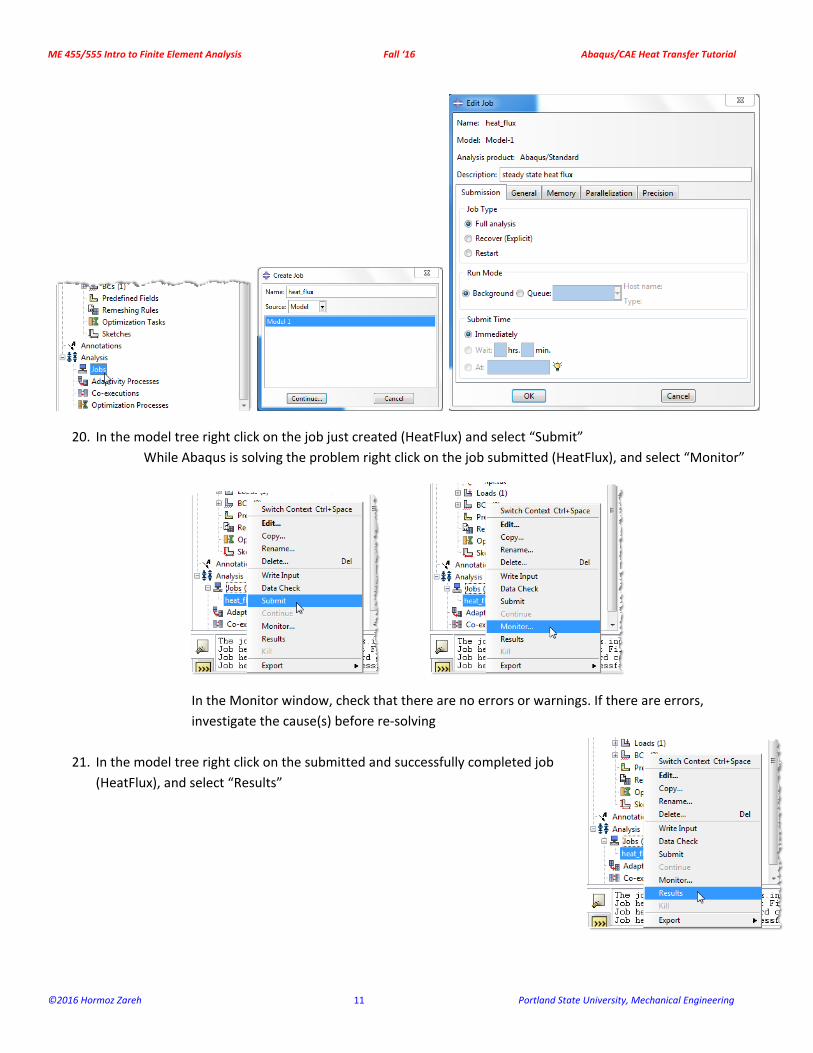
20. In the model tree right click on the job just created (HeatFlux) and select “Submit”
While Abaqus is solving the problem right click on the job submitted (HeatFlux), and select “Monitor”
In the Monitor window, check that there are no errors or warnings. If there are errors,
investigate the cause(s) before re‐solving
21. In the model tree right click on the submitted and successfully completed job
(HeatFlux), and select “Results”
ME 455/555 Intro to Finite Element Analysis Fall ‘16 Abaqus/CAE Heat Transfer Tutorial
©2016 Hormoz Zareh 12 Portland State University, Mechanical Engineering
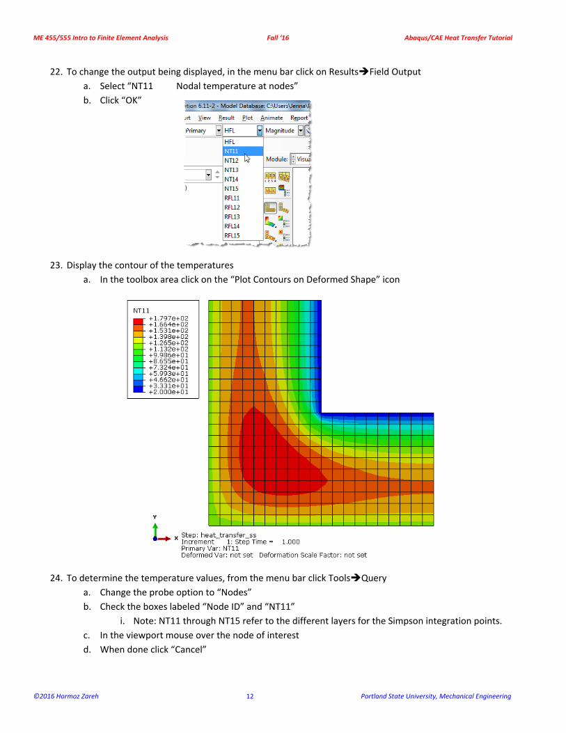
22. To change the output being displayed, in the menu bar click on ResultsField Output
a. Select “NT11 Nodal temperature at nodes”
b. Click “OK”
23. Display the contour of the temperatures
a. In the toolbox area click on the “Plot Contours on Deformed Shape” icon
24. To determine the temperature values, from the menu bar click ToolsQuery
a. Change the probe option to “Nodes”
b. Check the boxes labeled “Node ID” and “NT11”
i. Note: NT11 through NT15 refer to the different layers for the Simpson integration points.
c. In the viewport mouse over the node of interest
d. When done click “Cancel”