a03 ce journal wk 6 pdf
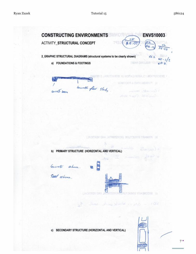
DESCRIPTION
ÂTRANSCRIPT

A03: Studio Journal Constructing Environments
Ryan Zuzek
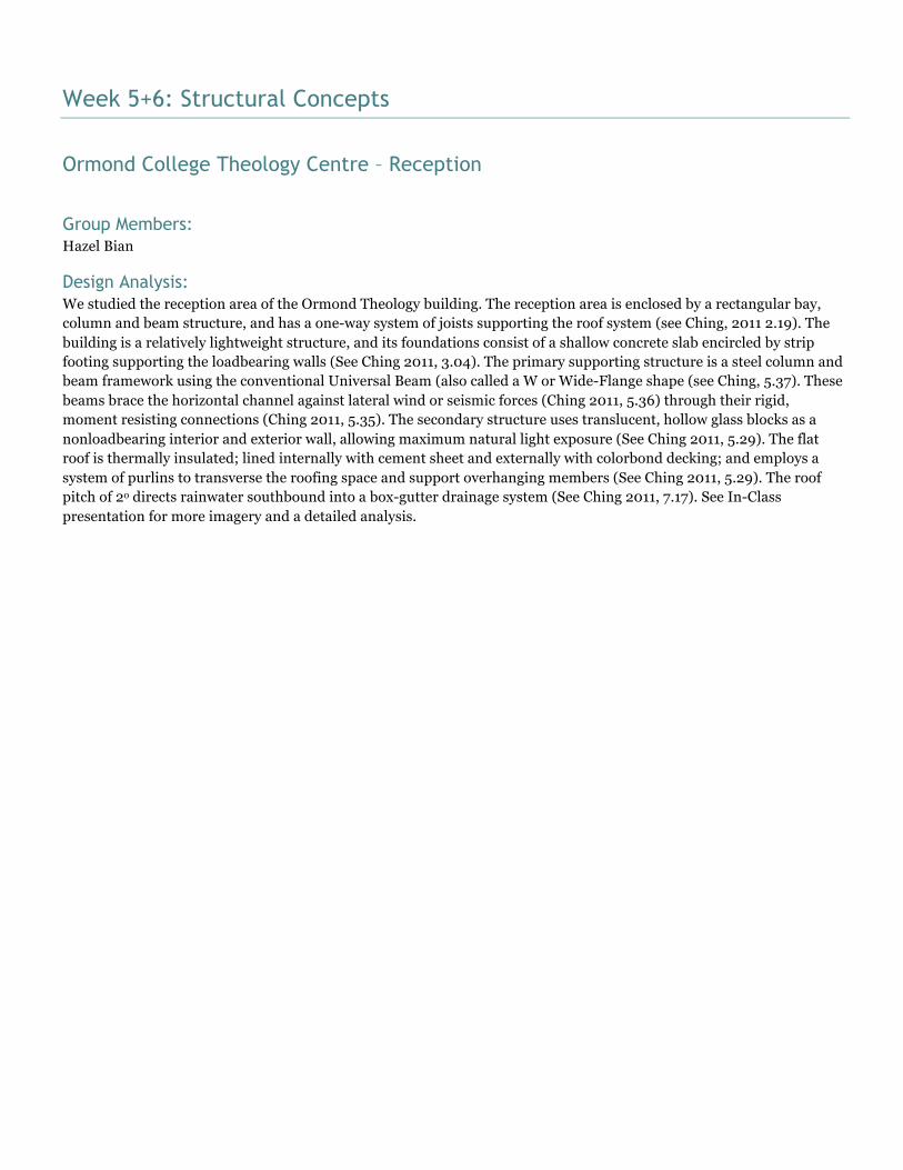
Week 5+6: Structural Concepts
Ormond College Theology Centre – Reception
Group Members: Hazel Bian
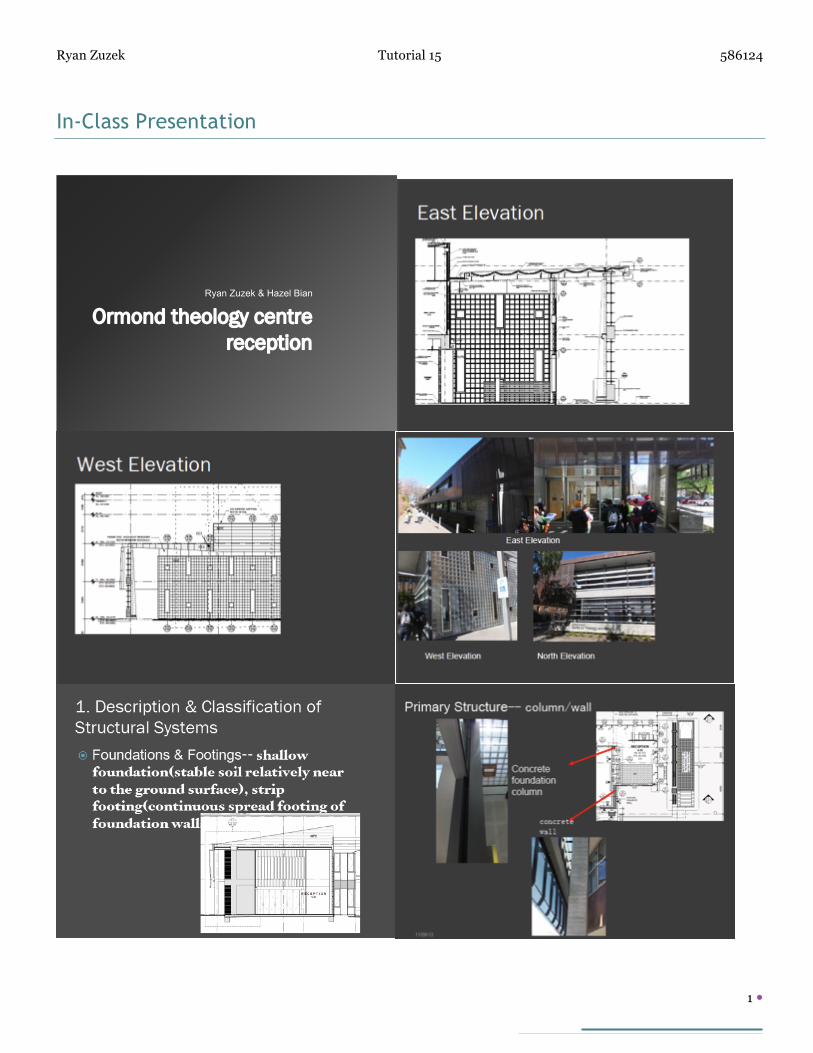
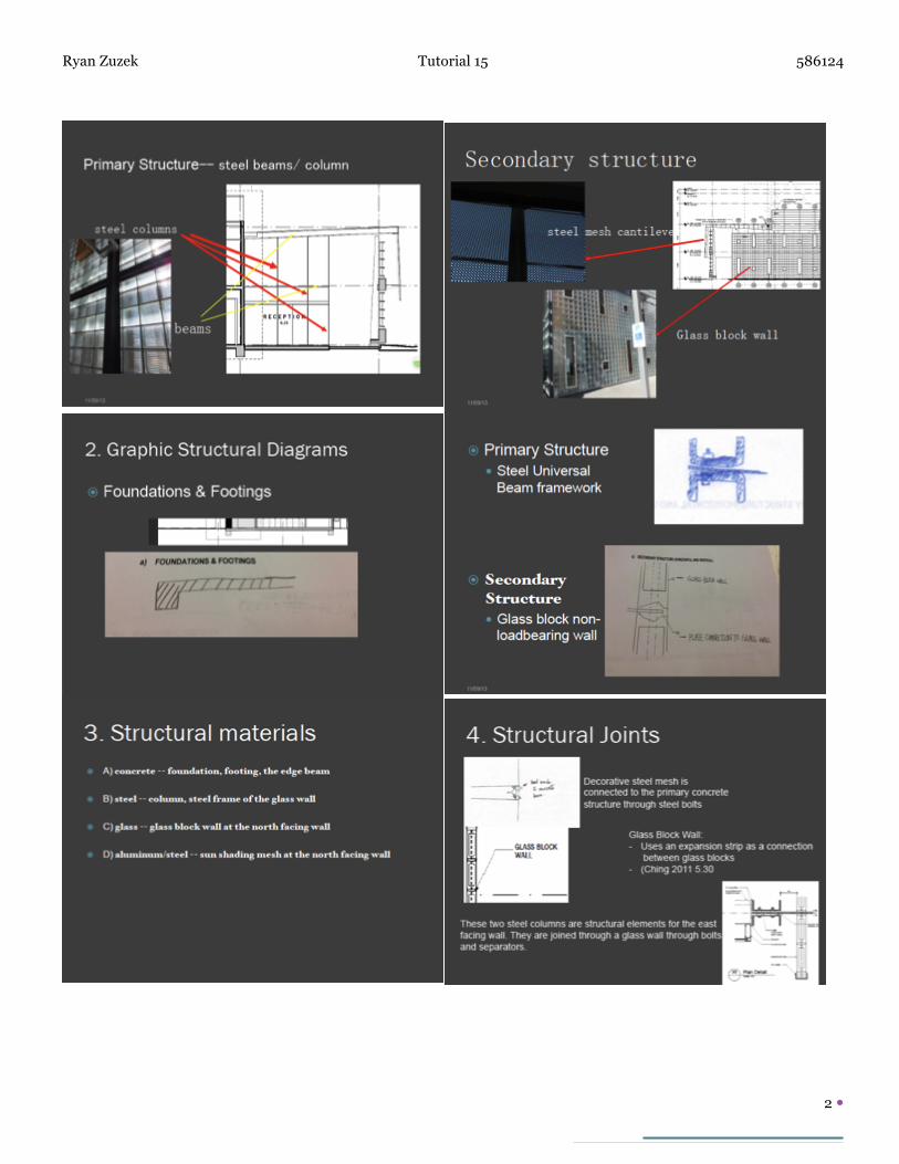
Design Analysis: We studied the reception area of the Ormond Theology building. The reception area is enclosed by a rectangular bay, column and beam structure, and has a one-way system of joists supporting the roof system (see Ching, 2011 2.19). The building is a relatively lightweight structure, and its foundations consist of a shallow concrete slab encircled by strip footing supporting the loadbearing walls (See Ching 2011, 3.04). The primary supporting structure is a steel column and beam framework using the conventional Universal Beam (also called a W or Wide-Flange shape (see Ching, 5.37). These beams brace the horizontal channel against lateral wind or seismic forces (Ching 2011, 5.36) through their rigid, moment resisting connections (Ching 2011, 5.35). The secondary structure uses translucent, hollow glass blocks as a nonloadbearing interior and exterior wall, allowing maximum natural light exposure (See Ching 2011, 5.29). The flat roof is thermally insulated; lined internally with cement sheet and externally with colorbond decking; and employs a system of purlins to transverse the roofing space and support overhanging members (See Ching 2011, 5.29). The roof pitch of 2o directs rainwater southbound into a box-gutter drainage system (See Ching 2011, 7.17). See In-Class presentation for more imagery and a detailed analysis.
Ryan Zuzek Tutorial 15 586124
1
In-Class Presentation
Ormond theology centre reception
Ryan Zuzek & Hazel Bian
Ryan Zuzek Tutorial 15 586124
2
Ryan Zuzek Tutorial 15 586124
3
Ryan Zuzek Tutorial 15 586124
4
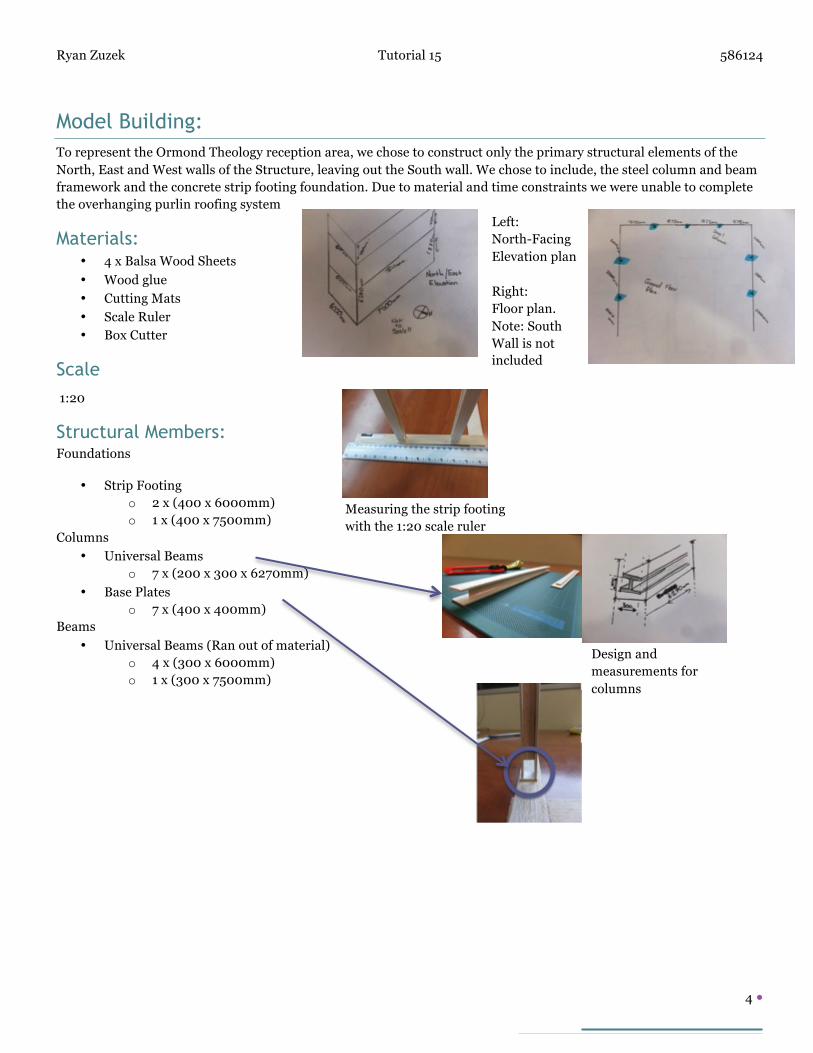
Model Building: To represent the Ormond Theology reception area, we chose to construct only the primary structural elements of the North, East and West walls of the Structure, leaving out the South wall. We chose to include, the steel column and beam framework and the concrete strip footing foundation. Due to material and time constraints we were unable to complete the overhanging purlin roofing system
Materials: • 4 x Balsa Wood Sheets
• Wood glue
• Cutting Mats
• Scale Ruler • Box Cutter
Scale 1:20
Structural Members: Foundations
• Strip Footing o 2 x (400 x 6000mm) o 1 x (400 x 7500mm)
Columns
• Universal Beams o 7 x (200 x 300 x 6270mm)
• Base Plates o 7 x (400 x 400mm)
Beams
• Universal Beams (Ran out of material) o 4 x (300 x 6000mm) o 1 x (300 x 7500mm)
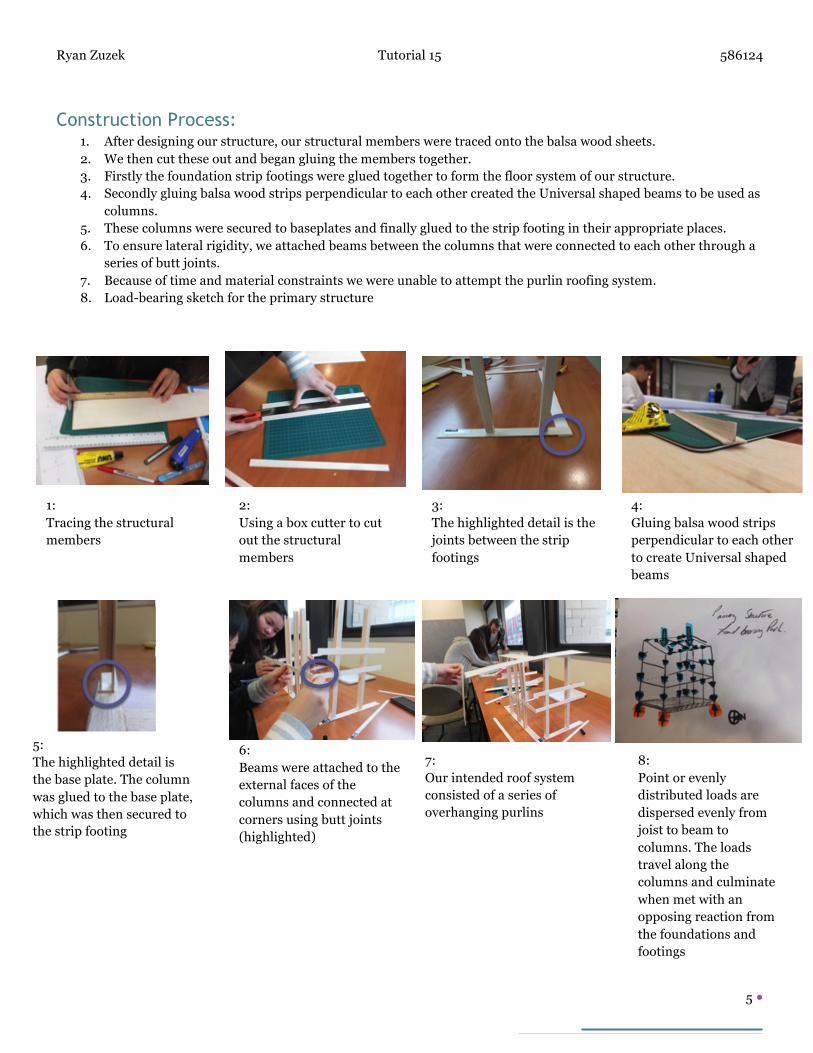
Measuring the strip footing with the 1:20 scale ruler
Left: North-Facing Elevation plan Right: Floor plan. Note: South Wall is not included
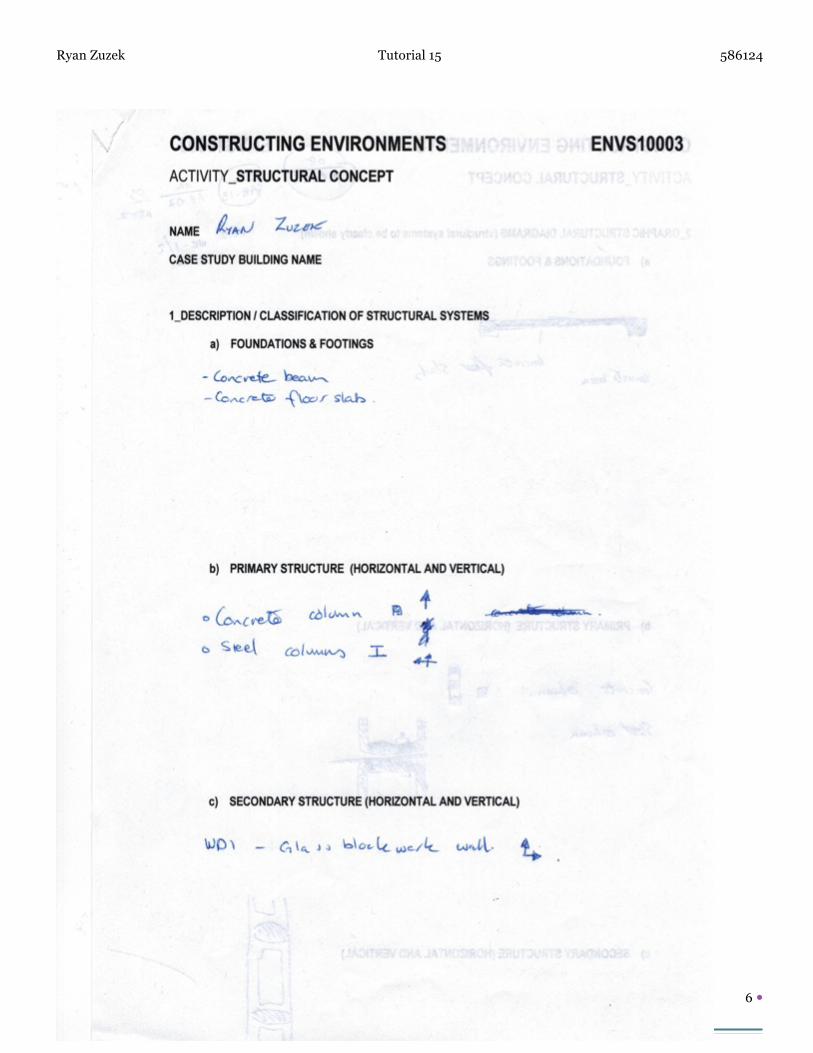
Design and measurements for columns
Ryan Zuzek Tutorial 15 586124
5
Construction Process: 1. After designing our structure, our structural members were traced onto the balsa wood sheets. 2. We then cut these out and began gluing the members together. 3. Firstly the foundation strip footings were glued together to form the floor system of our structure. 4. Secondly gluing balsa wood strips perpendicular to each other created the Universal shaped beams to be used as
columns. 5. These columns were secured to baseplates and finally glued to the strip footing in their appropriate places. 6. To ensure lateral rigidity, we attached beams between the columns that were connected to each other through a
series of butt joints. 7. Because of time and material constraints we were unable to attempt the purlin roofing system. 8. Load-bearing sketch for the primary structure
1: Tracing the structural members
2: Using a box cutter to cut out the structural members
3: The highlighted detail is the joints between the strip footings
4: Gluing balsa wood strips perpendicular to each other to create Universal shaped beams
5: The highlighted detail is the base plate. The column was glued to the base plate, which was then secured to the strip footing
6: Beams were attached to the external faces of the columns and connected at corners using butt joints (highlighted)
7: Our intended roof system consisted of a series of overhanging purlins
8: Point or evenly distributed loads are dispersed evenly from joist to beam to columns. The loads travel along the columns and culminate when met with an opposing reaction from the foundations and footings
Ryan Zuzek Tutorial 15 586124
6
Ryan Zuzek Tutorial 15 586124
7
Ryan Zuzek Tutorial 15 586124
8
Ryan Zuzek Tutorial 15 586124
9
Ryan Zuzek Tutorial 15 586124
10
Ryan Zuzek Tutorial 15 586124
11