a wideband dual-antenna receiver for wireless recording
TRANSCRIPT

A Wideband Dual-Antenna Receiver for WirelessRecording From Animals Behaving in LargeArenasSeung Bae Lee, Georgia Institute of TechnologyMing Yin, Brown UniversityJoseph Manns, Emory UniversityMaysam Ghovanloo, Georgia Institute of Technology
Journal Title: IEEE Transactions on Biomedical EngineeringVolume: Volume 60, Number 7Publisher: Institute of Electrical and Electronics Engineers (IEEE) | 2013-07,Pages 1993-2004Type of Work: Article | Post-print: After Peer ReviewPublisher DOI: 10.1109/TBME.2013.2247603Permanent URL: http://pid.emory.edu/ark:/25593/gj7g7
Final published version:http://ieeexplore.ieee.org/xpl/articleDetails.jsp?arnumber=6463438
Copyright information:© 2013 IEEE
Accessed March 23, 2022 9:11 PM EDT
A Wideband Dual-Antenna Receiver for Wireless RecordingFrom Animals Behaving in Large Arenas
Seung Bae Lee [Student Member, IEEE],GT-Bionics Laboratory, School of Electrical and Computer Engineering, Georgia Institute ofTechnology, Atlanta, GA 30308 USA
Ming Yin [Member, IEEE],School of Engineering, Brown University, Providence, RI 02912 USA
Joseph R. Manns, andDepartment of Psychology, Emory University, Atlanta, GA 30322 USA
Maysam Ghovanloo [Senior Member, IEEE]GT-Bionics Laboratory, School of Electrical and Computer Engineering, Georgia Institute ofTechnology, Atlanta, GA 30308 USASeung Bae Lee: [email protected]; Ming Yin: [email protected]; Joseph R. Manns: [email protected]; MaysamGhovanloo: [email protected]
AbstractA low-noise wideband receiver (Rx) is presented for a multichannel wireless implantable neuralrecording (WINeR) system that utilizes time-division multiplexing of pulse width modulated(PWM) samples. The WINeR-6 Rx consists of four parts: 1) RF front end; 2) signal conditioning;3) analog output (AO); and 4) field-programmable gate array (FPGA) back end. The RF front endreceives RF-modulated neural signals in the 403–490 MHz band with a wide bandwidth of 18MHz. The frequency-shift keying (FSK) PWM demodulator in the FPGA is a time-to-digitalconverter with 304 ps resolution, which converts the analog pulse width information to 16-bitdigital samples. Automated frequency tracking has been implemented in the Rx to lock onto thefree-running voltage-controlled oscillator in the transmitter (Tx). Two antennas and two parallelRF paths are used to increase the wireless coverage area. BCI-2000 graphical user interface hasbeen adopted and modified to acquire, visualize, and record the recovered neural signals in realtime. The AO module picks three demultiplexed channels and converts them into analog signalsfor direct observation on an oscilloscope. One of these signals is further amplified to generate anaudio output, offering users the ability to listen to ongoing neural activity. Bench-top testing of theRx performance with a 32-channel WINeR-6 Tx showed that the input referred noise of the entiresystem at a Tx–Rx distance of 1.5 m was 4.58 μVrms with 8-bit resolution at 640 kSps. In an invivo experiment, location-specific receptive fields of hippocampal place cells were mapped duringa behavioral experiment in which a rat completed 40 laps in a large circular track. Results werecompared against those acquired from the same animal and the same set of electrodes by acommercial hardwired recording system to validate the wirelessly recorded signals.
© 2013 IEEE
Correspondence to: Maysam Ghovanloo, [email protected].
Color versions of one or more of the figures in this paper are available online at http://ieeexplore.ieee.org.
NIH Public AccessAuthor ManuscriptIEEE Trans Biomed Eng. Author manuscript; available in PMC 2014 July 01.
Published in final edited form as:IEEE Trans Biomed Eng. 2013 July ; 60(7): 1993–2004. doi:10.1109/TBME.2013.2247603.
NIH
-PA Author Manuscript
NIH
-PA Author Manuscript
NIH
-PA Author Manuscript
Index TermsBehavioral neuroscience; in vivo; neural prosthesis; neural recording; pulse width modulation(PWM); wideband receiver
I. IntroductionEmerging technologies in bioelectronics, particularly those related to neuroprostheticdevices, have the potential to significantly improve patients’ quality of life. Equallyimportant are the tools that allow neuroscientists to conduct basic science experiments inneurophysiology research on animal models to understand the underlying principles behindoperation of the nervous system, its maladies, and possible therapies, such as deep brainstimulation, for which has shown significant clinical outcomes in treatment of Parkinson’sdisease, tremor, and other movement disorders [1]–[3]. Another example iselectrophysiological research to explore how the circuitry of the hippocampus supportsmemory [4]. Diseases that target the hippocampus, such as dementia and Alzheimer’s, arerapidly growing in the aging industrial societies and understanding fundamentals of thehealthy hippocampal memory system will be crucial for finding the causes and potentialremedies for such memory disorders.
A key objective has been increasing the number of simultaneously recorded channels whileminimizing damage to the neural tissue, degradation in the quality of the recorded neuralsignals, or biasing the natural animal behavior [5]–[12]. A related goal has been to designand develop high channel count wireless neural recording systems with potential clinicalapplications, such as brain–computer interfacing (BCI) for people with high level disabilitiesand amputees [13]–[15].
The majority of the research on wireless neural recording has so far been focused on thehigh density recording front ends and transmitting (Tx) side of the system, where the mainchallenges are miniaturization, low power consumption, and low noise to the extent that theTx side can eventually be implanted in the animal or human body. However, in a completewireless data acquisition system, additional components including antennas across thewireless link, external receiver (Rx), computer interface, postprocessing, data storage, andgraphical user interface (GUI) should all support the Tx unit for the entire system to operatesmoothly without losing information that is important for further processing of the neuralsignals.
Some of the major challenges in designing the Rx side are bandwidth, sensitivity, coverageof the experimental arena without leaving blind spots, and continuous streaming of theacquired data to the computer without any signal loss. In some early designs, analog sampleswere amplified, filtered, and directly fed into a voltage-controlled oscillator (VCO) on theTx side to be frequency modulated (FM) after time-division multiplexing (TDM) [6]. On theRx side, commercial FM receivers, such as the WinRadio (Melbourne, Australia) wereemployed. However, due to bandwidth limitation (~150 kHz) on the Rx side, such systemssuffered considerable crosstalk between channels, which also limited the number ofchannels to less than 10. Increasing the Rx bandwidth can alleviate these problems, asdemonstrated in a 32-ch wireless neural recording system by Triangle BioSystems, Inc.(Durham, NC, USA), which operates at 3.2 GHz using a custom-designed Rx with 300 MHzbandwidth [16]. Another advantage of increasing the carrier frequency is reducing the sizeof the optimal antennas. However, such frequencies are not useful for implantable devicesdue to significant absorption of high-frequency electromagnetic fields in the tissue [17].
Lee et al. Page 2
IEEE Trans Biomed Eng. Author manuscript; available in PMC 2014 July 01.
NIH
-PA Author Manuscript
NIH
-PA Author Manuscript
NIH
-PA Author Manuscript
Because of the previous limitations, most recent wireless neural recording systems have on-chip analog-to-digital converters (ADCs) on the Tx side followed by amplitude-shift keying(ASK), ON-/OFF-shift keying (OOK), frequency-shift keying (FSK), or phase-shift keyingto transmit digital samples in the industrial-scientific-medical (ISM) band. The Hermes-Dsystem, for instance, utilized an FSK scheme along with a 24-Mb/s custom-designedtransceiver [18]. Rizk et al. used a commercial ASK/OOK transceiver at 1 Mb/s from RFMonolithics (Dallas, TX, USA) for their 96-ch system [19], while Cheney et al. used acommercial 2.4-GHz FSK transceiver at 1 Mb/s from Nordic Semiconductor (Trondheim,Norway) for their 16-ch system [20]. High data rate digital systems require frequencystabilization components, such as crystals and phase-locked loops (PLL), to reduce thephase noise and ensure proper synchronization between Tx and Rx, which can increase thesize and power consumption of the Tx. Conversely, systems with lower data rates, encounterissues related to a limited number of channels, a low sampling rate per channel (which is notsuitable for single-unit recording), or challenges associated with extensive data reduction onthe Tx side [11], [21].
Using ultrawideband (UWB) transceivers is quite attractive due to their high data rate, lowmultipath interference, low power consumption, and relatively simple circuitry on the Txside. Chae et al. developed a 128-ch neural recording system operating at 3–5 GHz band[22]. They reported a maximum data rate of 90 Mb/s; however, neither separation betweenTx–Rx nor coverage of the experimental space was reported. Greenwald et al. alsodeveloped a 16-ch neural monitoring system with a controllable pulse rate between 90 and270 MHz band [23]. They also illustrated the functionality of the system in vivo. However, 1Mb/s of data rate is insufficient for neural recording systems with high channel count. AUWB transceiver was developed by Neuralynx (Bozeman, MT, USA) for another 128-chsystem, which offered 100 Mb/s of data rate supporting up to 18-bit resolution and 32 kSpsfor all channels [24]. However, the architecture of the Rx was not disclosed, and it is nolonger available. In general, although UWB transceivers offer many advantages, thisapproach is prone to interference from other RF sources. Also, due to the widespreadspectrum of the carrier-less short pulses, a long synchronization time is required to achievelossless signal acquisition and tracking on the Rx side. Moreover, complex signal processingmethods are necessary to recover data in noisy environments [25].
Increasing the Tx–Rx distance for full coverage of the experimental arena regardless of theTx position or orientation is a key requirement. Due to size limitations placed on powersources on the Tx side, this goal should ideally be achieved by consuming the least amountof power in the Tx RF block. The Tx antenna radiation pattern and its matching circuit alsoplay a significant role. Here, the challenge is designing the most efficient andomnidirectional antenna within the limited Tx dimensions. The signal-to-noise ratio (SNR)on the Rx side may rapidly degrade to undetectable levels even at short distances if there areblind spots within the experimental arena due to multipath or high directionality of the Tx orRx antennas. Robustness of the wireless link becomes even more important in systems withhigh channel count, in which low bit error rates are needed at tens of megabit per second.Constant movements of the Tx as the subject moves around the cage, resulting in the Txantenna loading variations, and the absence of frequency stabilization components on the Txare among other challenges.
Another key challenge that is often overlooked is the continuous, high throughput datatransfer from the Rx to the computer for further processing, display, and storage in real time.For example, a 32-channel system with at least 20 kSps per channel and 16 bits/sampleproduces 10 Mb/s of raw data. The computer interfacing hardware and software should bedesigned to continuously acquire and store such data volumes in real time without any dataloss or noticeable delay.
Lee et al. Page 3
IEEE Trans Biomed Eng. Author manuscript; available in PMC 2014 July 01.
NIH
-PA Author Manuscript
NIH
-PA Author Manuscript
NIH
-PA Author Manuscript

In the summary, these are the main requirements in designing the Rx side of wireless neuralrecording systems.
1. Compensating for size and power constraints on the Tx side, which prevent the useof complex frequency stabilization.
2. Wide bandwidth to support multiple channels without losing important neuralsignal information throughout the system.
3. Reliable coverage over the entire experimental arena without blind spots tocompensate for movements of the Tx.
4. Robustness against interference from other RF sources.
The following two sections describe how the Tx and Rx in the sixth generation of ourwireless integrated neural recording (WINeR-6) architecture address the aforementionedchallenges. Section IV shows the bench-top measurement results. Section V covers thebehavioral in vivo testing results on a rat animal model, followed by the concluding remarks.
II. WINeR-6 Transmitter ArchitectureThe WINeR-6 architecture is based on time-division multiplexing of pulse width modulated(TDM-PWM) signals [26]–[28]. It consists of a 32-channel wireless neural recording systemon a chip on the Tx side and a custom-designed Rx, shown on the left and right sides of Fig.1, respectively. The overall design strategy has been to reduce the complexity of the Tx unit,where size and power are extremely limited, at the cost of adding to the complexity of theRx unit.
Following amplification and filtering of the neural signals by an array of 32 low-noiseamplifiers (LNA), the outputs are combined with four monitoring signals, including half ofthe rectifier output voltage VREC/2, bandgap reference VG, a temperature-dependent voltageVT, and VSS, to be fed into the PWM block. The PWM block consists of 36 rail-to-railcomparators that compare analog inputs with a triangular waveform, similar to the analogportion of a single-slope ADC, to generate 36 PWM signals, as described in [26]–[29]. Inthis step that is known as analog-to-time conversion (ATC), the information stored in theanalog samples is converted to pulse width, and the pulses are multiplexed by a circular shiftregister (CSR). The TDM-PWM signal is a pseudodigital waveform with binary levels.Thus, it is more robust against interference compared to analog signals, and it can be easilytransmitted after a binary RF modulation. Hence, in this architecture, there is no need todigitize the samples on the Tx side, which can be a power- and area-consuming process athigh sampling rates. Moreover, wireless transmission of a high rate serial data bit stream attens of megabit per second requires more accurate timing and synchronization between theTx and Rx compared to a series of TDM-PWM pulses, which width can be preciselymeasured by a timer on the Rx side to recover the digitized data, in a step known as time-to-digital conversion (TDC) [30].
To save power, the CSR turns ON each channel only for a short period before and duringsampling. The comparator for each channel is also enabled only when that channel is beingsampled. During each comparison, WINeR-6 chip is entirely quiet with no digital transitionanywhere on the chip, reducing the substrate noise, pulse jitter, and dynamic powerdissipation. The monitoring signals provide a unique and fairly stable pattern that can beused to indicate the beginning of each TDM-PWM frame on the Rx side, which is necessaryfor demultiplexing of 36 samples. Following TDM, there is a PWM masking block, whichlimits the minimum width of the high and low TDS-PWM pulses to ensure their accuraterecovery on the Rx side.
Lee et al. Page 4
IEEE Trans Biomed Eng. Author manuscript; available in PMC 2014 July 01.
NIH
-PA Author Manuscript
NIH
-PA Author Manuscript
NIH
-PA Author Manuscript

The trimmed TDM-PWM signal drives a free-running hybrid VCO with an off-chipinductor, to be upconverted to a 428/441 MHz FSK signal. The FSK-TDM-PWM signal isthen 11.4 dB amplified by a class-C RF power amplifier and transmitted by a loop antennawith 18 MHz bandwidth.
A more detailed description of the WINeR-6 Tx can be found in [27].
III. WINeR-6 Receiver and Computer InterfaceResolution of the TDM-PWM-based WINeR-6 system is determined by the accuracy of therecovered pulse width. Higher Rx bandwidth corresponds with sharper pulse edges andlower pulse width error [28]. Thus, the WINeR-6 Rx needs high enough bandwidth toreceive the FSK-TDM-PWM signal while providing an adequate resolution of more than 8bits. Most commercially available ISM-band FSK receivers only provide up to 600 kHzbandwidth [31], which is far below what is required for a neural recording system with datavolume in the order of 10 Mb/s. Hence, we implemented a custom-designed Rx with 18MHz bandwidth using commercially available off-the-shelf (COTS) components.
The WINeR-6 Rx block diagram, shown in Fig. 1(b), has four major modules in addition tothe antennas: RF front end, analog signal conditioning, field-programmable gate array(FPGA) including USB 2.0 interface, and digital-to-analog converter (DAC).
A. Yagi–Uda AntennaLike other implantable medical devices, WINeR-6 Tx has a limited power budget for RFtransmission to keep its overall power consumption down. At the same time, it was desiredto provide coverage over large experimental arenas in the order of 2 × 2 m2 without anyblind spots. This specification required high Rx front-end sensitivity and high-gain Rxantennas. A Yagi–Uda antenna satisfies these requirements while offering wide bandwidth.Relatively high directivity of the Yagi–Uda antenna was mitigated by the inclusion of twoantennas in each WINeR-6 Rx. We designed a three-element Yagi–Uda antenna based on[32], as shown in Fig. 2.
B. RF Front EndIn order to increase the wireless coverage of the experimental arena and eliminate blindspots, the Rx was equipped with two identical RF front ends, each with its own antenna. Asshown in Fig. 1, the FSK-TDM-PWM signal from the Tx was picked up by each antenna,and amplified/filtered independently through its parallel RF front end. Each path has an RFpower detector (ADL5513), and depending on the strength of the received RF signal fromeach path, an RF switch connects the stronger one to the mixer. Depending on the size of theexperimental arena, the wireless coverage can potentially be extended even further byincreasing the number of antennas and parallel RF front-end paths.
Each RF front end consists of an RF-LNA (MAX2640) with a gain and noise figure of 15.1and 0.7 dB at 400 MHz, respectively, followed by a gain stage (BGA2712) that provides anadditional 24 dB amplification. The RF front end can provide up to 1.5 GHz bandwidth,while two passive third-order Cheby-shev bandpass filters with 403–490 MHz bandwidthare placed before and after the gain stage to provide selectivity around the Tx signal andlimit the out-of-band noise. The RF front end thus provides 45 dB gain and 87 MHzbandwidth.
Lee et al. Page 5
IEEE Trans Biomed Eng. Author manuscript; available in PMC 2014 July 01.
NIH
-PA Author Manuscript
NIH
-PA Author Manuscript
NIH
-PA Author Manuscript

C. Analog Signal ConditioningThe amplified and filtered FSK signal is fed into a mixer, which is a 50 MHz to 1 GHzquadrature demodulator with 75 MHz bandwidth (AD8348). The mixer has a built-invariable gain amplifier (VGA) that provides −18.5 to +25.5 dB programmable gain. TheVGA output drives two (I and Q) double-balanced Gilbert cell down-conversion mixers,which down convert the RF signal to 43.5/56.5 MHz IF band. The IF-TDM-PWM signal isthen further filtered and amplified in the baseband. To create a tunable local oscillator (LO)for the down converter, we have utilized a 720–1750 MHz VCO (V585ME41-LF) from Z-Comm (San Diego, CA, USA). The LO frequency is divided by two inside the mixer,resulting in its ability to receive RF frequencies in 360–875 MHz range.
IF amplifiers and filters improve the SNR by eliminating the out-of-band interference.AD4899-1 amplifier was chosen for this block because of its 300 MHz unity gainbandwidth, ultralow distortion, and low noise. Three instances of this amplifier have beenimplemented with a total IF gain of 46 dB. In order to reject all adjacent channels’interference, a bandpass filter (KR2850) from KR Electronics (Avenel, NJ, USA) has beenincluded between the second and the third amplifiers. The filter has an 18 MHz bandwidthfrom 41–59 MHz and a 1 dB pass-band ripple.
The amplified and filtered IF-FSK signal is fed into a logarithmic limiting IF amplifier(AD8309) and a high speed comparator (TLV3501) with 4.5 ns delay. This stage recoversthe rail-to-rail baseband FSK-TDM-PWM signal, which is then fed into an FPGA to be FMdemodulated in the digital domain to recover the TDM-PWM signal.
D. FPGA ModuleWe used a COTS FPGA module, called Xylo-EM [33], which includes an Altera FPGA(EP2C5T144C8), 2 MB of synchronous dynamic random access memory (SDRAM) for databuffering, and the USB interface circuitry.
1) FSK Demodulation via TDC—A TDC in the FPGA demodulates the down-convertedIF-FSK signal in the digital domain. The FPGA-based TDC block diagram is shown in Fig.3. The IF-FSK signal is used as the clock signal for the 8-bit encoder and D-type flip–flopsin the delay chain. A unit gate delay τ is the average time required for a rising or fallingedge to propagate through a four-input AND gate. As a falling edge of the IF-FSKpropagates through the chain of AND gates, the following rising edge saves a snapshot ofthe AND gate outputs in the rising edge-trigged D flip–flop register. Since the duration of alogic low is different in two FSK cycles at two different frequencies, the contents of the Dflip–flop register at every rising edge of the IF-FSK can determine the period of that FSKhalf-cycle, ΔT. The 8-bit encoder then converts the contents of the D flip–flop register to an8-bit value, C1[7:0] = ΔT/τ. The measured FSK pulse widths are accumulated in twoseparate registers, PWH and PWL, after comparing C1 with a programmable threshold valuethat discriminates between the two periods in the IF-FSK. The two frequencies in the IF-FSK are 43.5 and 56.5 MHz, which correspond to ΔT of 11.5 and 8.8 ns, respectively.Considering τ = 304 ps in this FPGA, ΔT/τ yields 38 and 29 delay cells for the low- andhigh-frequency half-cycles, respectively. To distinguish between these values, their average,34, was used for as the FSK period threshold.
Although the absolute values of PWH and PWL vary with the instantaneous changes in thetriangular waveform, the TDM-PWM duty cycle is relatively more stable and changesmainly with amplitude of the analog sample [28]. Thus, C2[14:0] was calculated inside theFPGA from PWH/(PWH + PWL) of the recovered TDM-PWM signal as a normalized valuewithin 0 and 1 that is proportional to the analog sample. C2 passes through a noise filtering
Lee et al. Page 6
IEEE Trans Biomed Eng. Author manuscript; available in PMC 2014 July 01.
NIH
-PA Author Manuscript
NIH
-PA Author Manuscript
NIH
-PA Author Manuscript

block, which removes the pulse widths that are too small or too large to eliminate sharpglitches. The demultiplexing block that follows is designed to detect the marker createdfrom four monitoring signals (VREC/2, VBG, VT, and VSS), which indicates the beginning ofeach TDM-PWM pulse frame. The pulse width following the monitoring signals is thesample taken from the first neural recording channel. In order to mark this channel for theBCI-2000, running on the computer, the demultiplexing block adds a flag to C3[14:0] as itsmost significant bit (MSB) such that the MSB of the 16 bits digitized output, C4[15:0],would be “1” for the first channel and “0” for all other channels.
2) Automatic Frequency Tracking (AFT)—Frequency stabilization components, suchas PLL or crystals, were not used in the WINeR-6 Tx to reduce its size and powerconsumption [27]. As a result, the Tx carrier frequency varies with temperature, supplyvoltage, and to a lesser extent antenna loading variations. To compensate for thesevariations, digital AFT function was implemented in the Rx. Following TDC, the AFT blockaverages 500 IF-FSK periods, which are available from C1[7:0]. The AFT tries to match thelow-pass-filtered carrier period from TDC with a programmable reference period bychanging the LO control voltage via a DAC. The AFT changes the LO frequency until thedown-converted IF-FSK spectrum is centered at 50 MHz.
3) Continuous High-Throughput USB Interface—A USB 2.0 interface delivers acontinuous stream of digitized neural data from WINeR-6 Rx to the computer in real time. Ahigh-speed EZ-USB chip (Cy7C68013A) was chosen for its high throughput,programmability, reliability, and ease of use. The data rate in the 32-ch WINeR-6 system isin the order of 10 Mb/s for 640 kSps. When USB operates in the burst mode, the delaysbetween successive USB data packets in the computer are quite unpredictable, varying from100 μs to a few ms. To ensure continuous real-time recording without data loss, we haveused a 2 MB SDRAM between the TDC and the USB interface blocks to buffer theincoming data. The EZ-USB chip is set to operate in the slave-FIFO mode, controlled by amaster module implemented in the Altera FPGA. The USB control module in the FPGAmanages data transfers between the SDRAM and USB. It writes the 16-bit data created inthe TDC module into the SDRAM at the falling edge of every TDM-PWM pulse. In thismodule, the EZ-USB reads a 16-bit sample from the SDRAM into its internal 2056 ByteFIFO. Meanwhile, the EZ-USB chip continuously checks its own FIFO state, and when it isfull, commits the data to the computer.
E. DAC ModuleTo assist users with visualizing and determining the quality of the incoming neural signalsand to be compatible with some commercial hardwired neural recording back ends,WINeR-6 Rx includes a four-channel 16-bit DAC (AD5664R), which operates at 71.1 kSps.The clock, data, and enable signals for the DAC are generated by the same FPGA, whichalso allows users to select 3 out of 32 digitized and demultiplexed neural recording channelsas inputs to the DAC. The DAC converts them into three analog signals that can be accessedindependently through SMA connectors. In addition, one of these three analog signals canbe selected and used to drive a 1-W audio amplifier with dc volume control (TDA7052A).The output of the audio amplifier drives an 8 Ω speaker, allowing users to identify the spikeactivity by how tit sounds. The first channel of the DAC is used in the AFC block, describedin Section III-D.3.
F. GUIBCI-2000, an open-source piece of software for BCI research applications, displays thereceived neural signals on the GUI and saves them on the computer hard disk in real time[34]. It consists of four modules that communicate within each other, as shown in Fig. 4(a).
Lee et al. Page 7
IEEE Trans Biomed Eng. Author manuscript; available in PMC 2014 July 01.
NIH
-PA Author Manuscript
NIH
-PA Author Manuscript
NIH
-PA Author Manuscript

The “source” module receives data from the data acquisition device (WINeR-6 Rx), saves it,and sends it to the signal processing module. The “application” module is responsible forvisualization on the computer screen. We have modified the source module to continuouslyreceive the neural data from WINeR-6 Rx through the USB port.
Fig. 4(b) shows the flowchart for data acquisition algorithm in the source module, whichperforms two important tasks. First, it detects the marker that indicates sampled data for thefirst channel and time-division demultiplexes the rest of the incoming data accordingly.While the program is running, the module waits for a predefined amount of data to arrive bysaving it in a temporary memory space before arranging the samples. Second, the sourcemodule applies a simple postprocessing algorithm to compensate for some of the nonlinearcharacteristics of the ATC process on the Tx side. The triangular waveform generator(TWG) block in particular has nonlinear characteristics that can degrade the quality of theTDM-PWM signal. In a one-time calibration process, the nonlinear characteristics of theTWG block in each WINeR-6 ASIC can be measured and stored in the BCI-2000 to beapplied to the incoming data from that ASIC before further signal processing.
The source module also receives a state vector from the “application” module and saves it ina file in *.dat format together with the organized raw data. The signal processing module isresponsible for a wide range of functions from various filters to spike detection,classification, and information extraction, desired by the user, which are out of the scope ofthis paper. It will pass on anything that needs to be visualized on the GUI to the applicationmodule, which also visualizes the received neural signals on the computer screen, andgenerates the state vector to be fed back to the source module. In this way, the BCI-2000software shows neural signals on the computer screen and saves them on the hard disk inreal time.
IV. Bench-Top Measurement ResultsThe RF, analog, and DAC modules of WINeR-6 Rx were implemented on separate custom-designed printed circuit boards for electromagnetic isolation and shielding, as shown in Fig.5. They are carefully fitted in a 17.9 × 17.5 × 7.6 cm3 aluminum enclosure along with theCOTS FPGA module and SMA interconnects. The WINeR-6 Rx consumes 80 and 290 mAfrom −5 and 5 V supplies, respectively. The FPGA module is powered from the USB port. Ithas on-board 3.3 and 5 V regulators, which also power the DAC module.
A. AntennasThe WINeR-6 Rx was bench-top tested along with the three-element Yagi–Uda antennas,designed based on specifications in Fig. 2. Fig. 6(a) shows the measured return loss of theantennas. Considering the effect of baluns, the 10 dB return loss of the fabricated antennasshows 54 MHz bandwidth, over the 424–478 MHz frequency range.
A loop antenna (3.5 × 2 cm2) was designed for the WINeR-6 Tx, as shown in the lower rightpanel in Fig. 5 [35]. The vertical and horizontal radiation patterns of the WINeR-6 Tx areshown in Fig. 6(b), which were measured in an outdoor open space to minimize externalinterference. The WINeR-6 Tx was placed in the center of the measurement area, and thereceived signal strength from the Yagi–Uda Rx antenna was measured at 1 m distance fromthe Tx. The Tx was manually rotated clockwise from 0° to 360° with 10° increments. Fig.6(b) shows that the WINeR-6 Tx antenna has maximum signal variation of 25 dB.
Lee et al. Page 8
IEEE Trans Biomed Eng. Author manuscript; available in PMC 2014 July 01.
NIH
-PA Author Manuscript
NIH
-PA Author Manuscript
NIH
-PA Author Manuscript
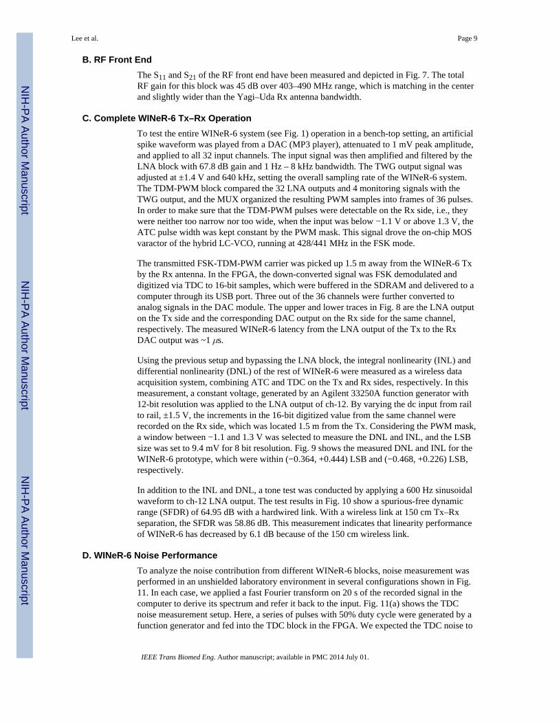
B. RF Front EndThe S11 and S21 of the RF front end have been measured and depicted in Fig. 7. The totalRF gain for this block was 45 dB over 403–490 MHz range, which is matching in the centerand slightly wider than the Yagi–Uda Rx antenna bandwidth.
C. Complete WINeR-6 Tx–Rx OperationTo test the entire WINeR-6 system (see Fig. 1) operation in a bench-top setting, an artificialspike waveform was played from a DAC (MP3 player), attenuated to 1 mV peak amplitude,and applied to all 32 input channels. The input signal was then amplified and filtered by theLNA block with 67.8 dB gain and 1 Hz – 8 kHz bandwidth. The TWG output signal wasadjusted at ±1.4 V and 640 kHz, setting the overall sampling rate of the WINeR-6 system.The TDM-PWM block compared the 32 LNA outputs and 4 monitoring signals with theTWG output, and the MUX organized the resulting PWM samples into frames of 36 pulses.In order to make sure that the TDM-PWM pulses were detectable on the Rx side, i.e., theywere neither too narrow nor too wide, when the input was below −1.1 V or above 1.3 V, theATC pulse width was kept constant by the PWM mask. This signal drove the on-chip MOSvaractor of the hybrid LC-VCO, running at 428/441 MHz in the FSK mode.
The transmitted FSK-TDM-PWM carrier was picked up 1.5 m away from the WINeR-6 Txby the Rx antenna. In the FPGA, the down-converted signal was FSK demodulated anddigitized via TDC to 16-bit samples, which were buffered in the SDRAM and delivered to acomputer through its USB port. Three out of the 36 channels were further converted toanalog signals in the DAC module. The upper and lower traces in Fig. 8 are the LNA outputon the Tx side and the corresponding DAC output on the Rx side for the same channel,respectively. The measured WINeR-6 latency from the LNA output of the Tx to the RxDAC output was ~1 μs.
Using the previous setup and bypassing the LNA block, the integral nonlinearity (INL) anddifferential nonlinearity (DNL) of the rest of WINeR-6 were measured as a wireless dataacquisition system, combining ATC and TDC on the Tx and Rx sides, respectively. In thismeasurement, a constant voltage, generated by an Agilent 33250A function generator with12-bit resolution was applied to the LNA output of ch-12. By varying the dc input from railto rail, ±1.5 V, the increments in the 16-bit digitized value from the same channel wererecorded on the Rx side, which was located 1.5 m from the Tx. Considering the PWM mask,a window between −1.1 and 1.3 V was selected to measure the DNL and INL, and the LSBsize was set to 9.4 mV for 8 bit resolution. Fig. 9 shows the measured DNL and INL for theWINeR-6 prototype, which were within (−0.364, +0.444) LSB and (−0.468, +0.226) LSB,respectively.
In addition to the INL and DNL, a tone test was conducted by applying a 600 Hz sinusoidalwaveform to ch-12 LNA output. The test results in Fig. 10 show a spurious-free dynamicrange (SFDR) of 64.95 dB with a hardwired link. With a wireless link at 150 cm Tx–Rxseparation, the SFDR was 58.86 dB. This measurement indicates that linearity performanceof WINeR-6 has decreased by 6.1 dB because of the 150 cm wireless link.
D. WINeR-6 Noise PerformanceTo analyze the noise contribution from different WINeR-6 blocks, noise measurement wasperformed in an unshielded laboratory environment in several configurations shown in Fig.11. In each case, we applied a fast Fourier transform on 20 s of the recorded signal in thecomputer to derive its spectrum and refer it back to the input. Fig. 11(a) shows the TDCnoise measurement setup. Here, a series of pulses with 50% duty cycle were generated by afunction generator and fed into the TDC block in the FPGA. We expected the TDC noise to
Lee et al. Page 9
IEEE Trans Biomed Eng. Author manuscript; available in PMC 2014 July 01.
NIH
-PA Author Manuscript
NIH
-PA Author Manuscript
NIH
-PA Author Manuscript
be very small, but it should be noted that the measurement included the function generatorphase noise as well, which was considered negligible. In Fig. 11(b), the LNA outputs areforced to ground to cancel the LNA noise. Noise of the wireless link has also been bypassedby directly connecting the TDM-PWM signal from Tx to the TDC input on the Rx sidethrough a high-speed digital isolator (ISO721). The setup in Fig. 11(c) is similar to the onein Fig. 11(b) except for the fact that the LNA noise has been included by grounding theLNA inputs. Finally, Fig. 11(d) shows the noise measurement setup for the entire WINeR-6system. In all noise measurements, the LNA bandwidth was set to 200 Hz to 8 kHz, whilethe input referred noise was integrated over a wider range from 1 Hz to 10 kHz.
Using the setup in Fig. 11(d) (i.e. the entire system), we swept the Tx–Rx distance from 30to 210 cm to observe the effect of Tx–Rx separation on the noise of the wireless link withoutshielding. The input referred noise amplitudes for these measurements are shown in Figs. 12and 13. According to these graphs and our theoretical analysis in [28], the noise from thewireless Rx is obviously the dominant noise source for the current 32-ch WINeR-6 systemprototype, especially at large Tx–Rx separation. At the nominal Tx–Rx distance of 1.5 m,the effective number of bits is 8 bits considering the INL and DNL measurements in Fig. 9.In addition, the measured Rx sensitivity was −65 dBm. Table I summarizes the keymeasured specifications of the entire WINeR-6 system.
V. In Vivo Experimental ResultsTo further evaluate the performance of the WINeR-6 system, we compared its overallperformance to that of a commercial hardwired system, based on NSpike [36], in ameaningful behavioral neuroscience experiment, in which action potentials were recordedfrom hippocampal pyramidal neurons of a rat as it completed laps on a relatively largecircular track (~1 m2). The subject was a 15-month-old male Long-Evans rat, weighingapproximately 550 g. This set of experiments was conducted with approvals from theInstitutional Animal Care and Use Committees at the Georgia Institute of Technology andEmory University.
The rat was implanted with a chronic recording assembly that contained 32 tetrodes (bundleof four electrodes) targeted at the dorsal hippocampus. Further details can be found in [37]and [38]. The electrodes were connected to four 36-pin male Nanoconnectors fromOmnetics (Minneapolis, MN, USA). In each of the four connectors, four lateral pins wereused for grounding and reference, and the other 32 were connected to 8 out of 32 tetrodes.The WINeR-6 analog front-end bandwidth for this experiment was set to 400 Hz–8 kHzwith a total gain of 8000 for recording single-neuron action potentials, similar to the settingsfor the NSpike system. The experiment was carried out in a circular track with an outerdiameter of 91.4 cm and width of 7.6 cm, as shown in Fig. 14, which was setup in a smallshielded cubicle. During the test, the rat completed two sessions of 40 laps each, in whichvideo and neural data were recorded with both systems. The rat was rewarded forcompleting each lap with a small piece of chocolate.
To provide sufficient wireless coverage, four antennas from two WINeR-6 receivers weremounted on stands made of PVC pipes, and positioned roughly at 3, 6, 9, and 12 o’clockslightly above the circular track in order not to miss any neural signal during the experimentdue to fading. The two WINeR-6 Rxs and associated computers were placed outside thecubicle.
Fig. 15 shows the operating diagram of the dual-Rx solution. When two receivers record thesame neural signals from a single WINeR-6 Tx, the data need to be synchronized byindicating the same marker signals in both recorded data streams. For this purpose, apredefined marker was generated in the master FPGA when a push button was pressed. This
Lee et al. Page 10
IEEE Trans Biomed Eng. Author manuscript; available in PMC 2014 July 01.
NIH
-PA Author Manuscript
NIH
-PA Author Manuscript
NIH
-PA Author Manuscript
marker signal was then transferred to the master BCI-2000, and easily distinguished fromthe digitized neural signals. A similar marker signal was generated in the slave FPGA at thesame time and sent to the slave BCI-2000. Fig. 16 shows a snapshot of 32 neural recordingchannels which was shown in real time on one of the two BCI-2000 GUIs. A similarWINeR-6 configuration could be used to simultaneously record neural signals from multipleanimal subjects in the same experimental arena in a socially relevant context, provided thattheir Tx–Rx pairs were tuned at different center frequencies.
The exact same experiment was repeated with the same animal and the same electrodepositions using the hardwired NSpike system, for which sampling rate, gain, and bandwidthwere adjusted to be very close to that of the WINeR-6 system. A video camera was mountedabove the track to record the rat position in synchrony with the neural recording. The videoframes were synchronized with the neural data from WINeR-6 by flashing the LED, shownin Fig. 15, as an optical cue.
After completion of the data recording phase, spike classification was conducted on bothwireless and hardwired datasets using the Offline Sorter software from Plexon (Dallas, TX,USA) in order to isolate activity from individual neurons. Fig. 17(a) and (b) shows spikewaveforms across four channels (wires) of the same tetrode, activity from what was thoughtto be the same pyramidal neuron recorded during the WINeR-6 (wireless) and NSpike(hardwired) sessions, respectively. After classifying putative single neurons, the spike firinglocation for the best isolated units were marked on the circular track by synchronizing thetiming of the spiking activity with the rat location on the recorded video data.
Many pyramidal neurons in the dorsal rat hippocampus, termed place cells, show location-specific activity, and the location at which the greatest firing rate of an individual neuronoccurs is often referred to as its place field [39]. Fig. 18 shows a place field plot for a place-cell recorded during both recording sessions. Brighter colors indicate a higher firing rate,and gray colors show the overlapping trajectories of the rat as it completed laps on thecircular track. Based on the similar spatial selectivity of the place fields in both plots andsimilar firing rates, the results suggest that the WINeR-6 wirelessly recorded data are similarto that of the hardwired recording setup (gold standard) in an experiment with a rat freelybehaving in a 1-m2 arena. The results illustrate the feasibility of the WINeR-6 system as asubstitute for hardwired systems in behavioral neuroscience experiments. The lower SNR ofthe WINeR-6 system, which is also noticeable in Fig. 17 classified single- neuronwaveforms, has resulted in lower concentration of the place cell firing around the peak inFig. 18.
VI. ConclusionWe have presented a complete high performance multichannel WINeR system withemphasis on the Rx side. WINeR-6 architecture offers 18 MHz RF bandwidth and high datathroughput all the way from the neural tissue to the computer for real-time electrical, visual,and acoustic representation of 32 simultaneously recorded channels. A significant feature ofthe WINeR-6 system, which has been demonstrated in a real behavioral neuroscienceexperiment on an awake freely behaving small animal subject (rat), is its ability to providewireless coverage over a large experimental arena (>1 m2) without losing data or leavingany blind spots, while keeping the Tx power consumption, the SNR, and resolution of theentire system at a reasonable level. Utilization of the TDM-PWM method to simplify the Tx,multiple custom-designed high gain antennas, automatic Tx carrier frequency tracking, high-resolution FPGA-based FSK demodulation, and TDC are some of the techniques that havesignificantly improved WINeR-6 performance compared to systems with similar complexityand power consumption. We are now working to further improve the WINeR system
Lee et al. Page 11
IEEE Trans Biomed Eng. Author manuscript; available in PMC 2014 July 01.
NIH
-PA Author Manuscript
NIH
-PA Author Manuscript
NIH
-PA Author Manuscript

resolution, noise performance, and power consumption to be wirelessly powered inside asmart experimental arena, known as the EnerCage [27], [40].
AcknowledgmentsThis work was supported in part by the National Institute of Health, NINDS Grant 1R01NS062031-01A1, and theNational Science Foundation under Award ECCS-824199.
The authors would like to thank F. Getaneh in the Manns lab and several members of the GT-Bionics lab for theirassistance with the animal experiments.
References1. Breit S, Schulz JB, Benabid AL. Deep brain stimulation. Cell Tissue Res. Aug.2004 318:275–288.
[PubMed: 15322914]
2. Holtzheimer PE, Mayberg HS. Deep brain stimulation for psychiatric disorders. Ann Rev Neurosci.2011; 34:289–307. [PubMed: 21692660]
3. Wichmann T, Delong MR. Deep brain stimulation for neurologic and neuropsychiatric disorders.Neuron. Oct; 2006 52(1):197–204. [PubMed: 17015236]
4. Manns JR, Eichenbaum H. Evolution of declarative memory. Hippocampus. Sep; 2006 16(9):795–808. [PubMed: 16881079]
5. Johannessen EA, Wang L, Cui L, Tang TB, Ahmadian M, Astaras A, Reid SWJ, Yam PS, MurrayAF, Flynn BW, Beaumont SP, Cumming DRS, Cooper JM. Implementation of multichannel sensorsfor remote biomedical measurements in a microsystems format. IEEE Trans Biomed Eng. Mar;2004 51(3):525–535. [PubMed: 15000383]
6. Mohseni P, Najafi K, Eliades SJ, Wang X. Wireless multichannel biopotential recording using anintegrated FM telemetry circuit. IEEE Trans Neural Syst Rehabil Eng. Sep; 2005 13(3):263–271.[PubMed: 16200750]
7. Sawan M, Hu Y, Coulombe J. Wireless smart implants dedicated to multichannel monitoring andmicrostimulation. IEEE Circuits Syst Mag. 2005; 5(1):21–39.
8. Harrison RR, Watkins PT, Kier RJ, Lovejoy RO, Black DJ, Greger B, Solzbacher F. A low-powerintegrated circuit for a wireless 100-electrode neural recording system. IEEE J Solid-State Circuits.Jan; 2007 42(1):123–133.
9. Sodagar AM, Wise KD, Najafi K. A fully integrated mixed-signal neural processor for implantablemultichannel cortical recording. IEEE Trans Biomed Eng. Jun; 2007 54(6):1075–1088. [PubMed:17554826]
10. Peng CC, Zhiming X, Bashirullah R. Toward energy efficient neural interface. IEEE Trans BiomedEng. Nov; 2009 56(11):2697–2700. [PubMed: 19709960]
11. Farshchi S, Pesterev A, Nuyujukian P, Guenterberg E, Mody I, Judy JW. Embedded neuralrecording with tinyOS-based wireless-enabled processor modules. IEEE Trans Neural SystRehabil Eng. Apr; 2010 18(2):134–141. [PubMed: 20071270]
12. Gosselin B. Recent advances in neural recording microsystems. Sensors. Apr.2011 11:4572–4597.[PubMed: 22163863]
13. Nurmikko AV, Donoghue JP, Hochberg LR, Patterson WR, Song YK, Bull CW, Borton DA,Laiwalla F, Park S, Yin M, Aceros J. Listening to brain microcircuits for interfacing with externalworld—Progress in wireless implantable microelectronic neuroengineering devices. Proc IEEE.Mar; 2010 98(3):375–388.
14. Lebedev MA, Nicolelis MAL. Brain–machine interfaces: Past, present and future. TrendsNeurosci. Jul; 2006 29(9):536–546. [PubMed: 16859758]
15. Hochberg LR, Donoghue JP. Sensors for brain computer interfaces. IEEE Eng Med Biol Mag. Sep;2006 25(5):32–38. [PubMed: 17020197]
16. Fan D, Rich D, Holtzman T, Ruther P, Dalley JW, Lopez A, Rossi MA, Barter JW, Salas-Meza D,Herwik S, Holzhammer T, Morizio J, Yin HH. A wireless multichannel recording system forfreely behaving mice and rats. PLoS ONE Neurosci. Jul.2011 6(7)10.1371/journal.pone.0022033
Lee et al. Page 12
IEEE Trans Biomed Eng. Author manuscript; available in PMC 2014 July 01.
NIH
-PA Author Manuscript
NIH
-PA Author Manuscript
NIH
-PA Author Manuscript

17. Poon AY, O’Driscoll S, Meng TH. Optimal frequency for wireless power transmission intodispersive tissue. IEEE Trans Antennas Propag. May; 2010 58(5):1739–1750.
18. Miranda H, Gilja V, Chestek CA, Shenoy KV, Meng TH. HermesD: A high-rate long-rangewireless transmission system for simultaneous multichannel neural recording applications. IEEETrans Biomed Circuits Syst. Jun; 2010 4(3):181–191. [PubMed: 23853342]
19. Rizk M, Obeid I, Callender SH, Wolf PD. A single-chip signal processing and telemetry engine foran implantable 96-channel neural data acquisition system. J Neural Eng. Jun.2007 4:309–21.[PubMed: 17873433]
20. Cheney D, Goh A, Xu J, Gugel K, Harris JG, Sanchez JC, Principe JC. Wireless, in vivo neuralrecording using a custom integrated bioamplifier and the pico system,” in. Proc 3rd IEEE Int EngMed Biol Soc Conf Neural Eng. Mar.2007 :19–22.
21. Zhang F, Aghagolzadeh M, Oweiss K. A fully implantable, programmable and multimodalneuroprocessor for wireless, cortically controlled brain-machine interface applications. J SignalProcess Syst. Mar.2012 69:351–361. [PubMed: 23050029]
22. Chae M, Yang Z, Yuce MR, Hoang L, Liu W. A 128-channel 6 mW wireless neural recording ICwith spike feature extraction and UWB transmitter. IEEE Trans Neural Syst Rehabil Eng. Aug;2009 17(4):312–321. [PubMed: 19435684]
23. Greenwald E, Mollazadeh M, Hu C, Tang W, Culurciello E, Thakor NV. A VLSI neuralmonitoring system with ultra-wideband telemetry for awake behaving subjects. IEEE TransBiomed Circuits Syst. Apr; 2011 5(2):112–119. [PubMed: 23851199]
24. Neuralynx Corp; Bozeman, MT, USA: [Online]. Available: http://www.neuralynx.com
25. Mercier PP, Bhardwaj M, Daly DC, Chandrakasan AP. A low-voltage energy-sampling IR-UWBdigital baseband employing quadratic correlation. IEEE J Solid-State Circuits. Jun; 2010 45(6):1209–1219.
26. Yin M, Ghovanloo M. A low-noise clockless simultaneous 32-channel wireless neural recordingsystem with adjustable resolution. Analog Integrated Circuits and Signal Process. Mar; 201166(3):417–431.
27. Lee SB, Lee H, Kiani M, Jow U, Ghovanloo M. An inductively powered scalable 32-channelwireless neural recording system-on-a-chip for neuroscience applications. IEEE Trans BiomedCircuits Syst. Dec; 2010 4(6):360–371. [PubMed: 23850753]
28. Yin M, Ghovanloo M. Using pulse width modulation for wireless transmission of neural signals inmultichannel neural recording systems. IEEE Trans Neural Syst Rehabil Eng. Aug; 2009 17(4):354–363. [PubMed: 19497823]
29. Baker, RJ. CMOS Circuit Design, Layout, and Simulation. 3. Hoboken, NJ, USA: Wiley; 2010.
30. Kalisz J, Szplet R, Poniecki A. Field programmable gate array based time-to-digital converter with200-ps resolution. IEEE Trans Instrum Meas. Feb; 1997 46(1):51–55.
31. Analog Devices, ADF7025, High Performance ISM-Band Transceiver IC. [Online]. Available:http://www.analog.com/static/imported-files/data_sheets/ADF7025.pdf
32. Milligan, TA. Modern Antenna Design. 2. Hoboken, NJ, USA: Wiley; 2005.
33. FX2 FPGA & ARM Boards, KNJN LLC. [Online]. Available: http://www.knjn.com/FPGA-FX2.html
34. BCI-2000 Homepage. [Online]. Available: http://www.bci2000.org
35. Nordic Semiconductor, nAN900—05 nRF9E5 RF and Antenna Layout. [Online]. Available: http://www.nordicsemi.com/eng/content/download/2449/29496/file/nAN900-05_nRF9E5_RF_and_antenna_layout_rev2_1.pdf
36. NSpike. [Online]. Available: http://nspike.sourceforge.net/
37. Komorowski RW, Manns JR, Eichenbaum H. Robust conjunctive item-place coding byhippocampal neurons parallels learning what happens where. J Neurosci. Aug; 2009 29(31):9918–9929. [PubMed: 19657042]
38. Manns JR, Eichenbaum H. A cognitive map for object memory in the hippocampus. LearningMemory. Sep; 2009 16(10):616–624. [PubMed: 19794187]
39. O’Keefe J. Place units in the hippocampus of the freely moving rat. Exp Neurol. Apr; 1976 51(1):78–109. [PubMed: 1261644]
Lee et al. Page 13
IEEE Trans Biomed Eng. Author manuscript; available in PMC 2014 July 01.
NIH
-PA Author Manuscript
NIH
-PA Author Manuscript
NIH
-PA Author Manuscript

40. Jow U, Kiani M, Huo X, Ghovanloo M. Towards a smart experimental arena for long-termelectrophysiology experiments. IEEE Trans Biomed Circuits Syst. Oct; 2012 6(5):414–423.[PubMed: 23853228]
Biographies
Seung Bae Lee (S′08) received the B.S. degree in electrical engineering from HanyangUniversity, Seoul, Korea, in 2007 and the M.S. degree in electrical and computerengineering from the Georgia Institute of Technology, Atlanta, GA, USA, in 2010. He iscurrently working toward the Ph.D. degree at the Georgia Institute of Technology.
He came to Georgia Tech in August 2007 and joined GT-Bionics Laboratory in May 2008.His current research interest includes an ultralow power RF receiver for biomedical andwearable applications as well as a wireless neural recording system.
Ming Yin (S′06–M′10) received the B.S. and M.S. degrees in electronics engineering fromTsinghua University, Beijing, China, and the Ph.D. degree in electrical engineering fromNorth Carolina State University, Raleigh, NC, USA.
He is currently a Postdoctoral Fellow at Brown University, Providence, RI, USA, workingon a wireless neural recording system. His research interests include low noise, low poweranalog/mixed circuit design for wireless biomedical applications.
Joseph R. Manns received the Ph.D. degree in psychology from the University ofCalifornia, San Diego, San Diego, CA, USA, in 2002.
Lee et al. Page 14
IEEE Trans Biomed Eng. Author manuscript; available in PMC 2014 July 01.
NIH
-PA Author Manuscript
NIH
-PA Author Manuscript
NIH
-PA Author Manuscript
After completing a postdoctoral fellowship at Boston University in 2007, he joined thefaculty at Emory University, Atlanta, GA, USA, where he is currently an Assistant Professorin the Department of Psychology.
Dr. Manns received the postdoctoral Ruth L. Kirschstein National Research Service Award(2003–2006) and the Pathway to Independence Award (K99/R00; 2006–2011) by theNational Institutes of Health.
Maysam Ghovanloo (S′00–M′04–SM′10) was born in Tehran, Iran, in 1973. He receivedthe B.S. degree in electrical engineering from the University of Tehran, Tehran, in 1994, theM.S. degree in biomedical engineering from the Amirkabir University of Technology,Tehran, in 1997, and the M.S. and Ph.D. degrees in electrical engineering from theUniversity of Michigan, Ann Arbor, MI, USA, in 2003 and 2004, respectively.
From 2004 to 2007, he was an Assistant Professor in the Department of Electrical andComputer Engineering, North Carolina State University, Raleigh, NC, USA. In June 2007,he joined the faculty of Georgia Institute of Technology, Atlanta, GA, USA, where he iscurrently an Associate Professor and the Founding Director of the GT-Bionics Laboratory atthe School of Electrical and Computer Engineering. He has authored or coauthored morethan 100 peer-reviewed conference and journal publications.
Dr. Ghovanloo is an Associate Editor of the IEEE Transactions on Biomedical Engineering,IEEE Transactions on Biomedical Circuits and Systems, and a member of the Imagers,MEMS, Medical, and Displays subcommittee at the International Solid-State CircuitsConference. He also served on the editorial board for the IEEE Transactions on Circuits andSystems, PART-II from 2007 to 2011. He received the 2010 CAREER Award from theNational Science Foundation. He received the Tommy Nobis Barrier Breaker Award forInnovation and the Distinguished Young Scholar Award from the Association of Professorsand Scholars of Iranian Heritage. He has organized several special sessions and was amember of Technical Review Committees for major conferences in the areas of circuits,systems, sensors, and biomedical engineering. He is a member of the Tau Beta Pi, AAAS,Sigma Xi, IEEE Solid-State Circuits Society, IEEE Circuits and Systems Society, and IEEEEngineering in Medicine and Biology Society.
Lee et al. Page 15
IEEE Trans Biomed Eng. Author manuscript; available in PMC 2014 July 01.
NIH
-PA Author Manuscript
NIH
-PA Author Manuscript
NIH
-PA Author Manuscript
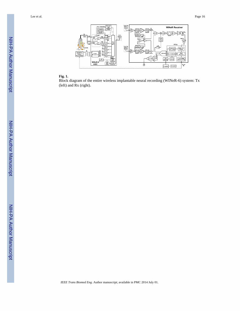
Fig. 1.Block diagram of the entire wireless implantable neural recording (WINeR-6) system: Tx(left) and Rx (right).
Lee et al. Page 16
IEEE Trans Biomed Eng. Author manuscript; available in PMC 2014 July 01.
NIH
-PA Author Manuscript
NIH
-PA Author Manuscript
NIH
-PA Author Manuscript

Fig. 2.Three-element Yagi–Uda dipole antenna designed for 433 MHz carrier.
Lee et al. Page 17
IEEE Trans Biomed Eng. Author manuscript; available in PMC 2014 July 01.
NIH
-PA Author Manuscript
NIH
-PA Author Manuscript
NIH
-PA Author Manuscript
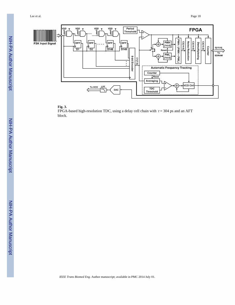
Fig. 3.FPGA-based high-resolution TDC, using a delay cell chain with τ = 304 ps and an AFTblock.
Lee et al. Page 18
IEEE Trans Biomed Eng. Author manuscript; available in PMC 2014 July 01.
NIH
-PA Author Manuscript
NIH
-PA Author Manuscript
NIH
-PA Author Manuscript

Fig. 4.(a) Core modules and their interactions in the BCI-2000. (b) Data acquisition flowchart ofthe “Source” module.
Lee et al. Page 19
IEEE Trans Biomed Eng. Author manuscript; available in PMC 2014 July 01.
NIH
-PA Author Manuscript
NIH
-PA Author Manuscript
NIH
-PA Author Manuscript
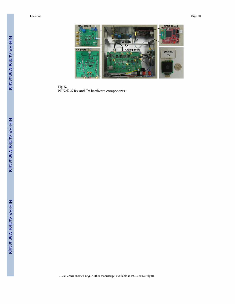
Fig. 5.WINeR-6 Rx and Tx hardware components.
Lee et al. Page 20
IEEE Trans Biomed Eng. Author manuscript; available in PMC 2014 July 01.
NIH
-PA Author Manuscript
NIH
-PA Author Manuscript
NIH
-PA Author Manuscript
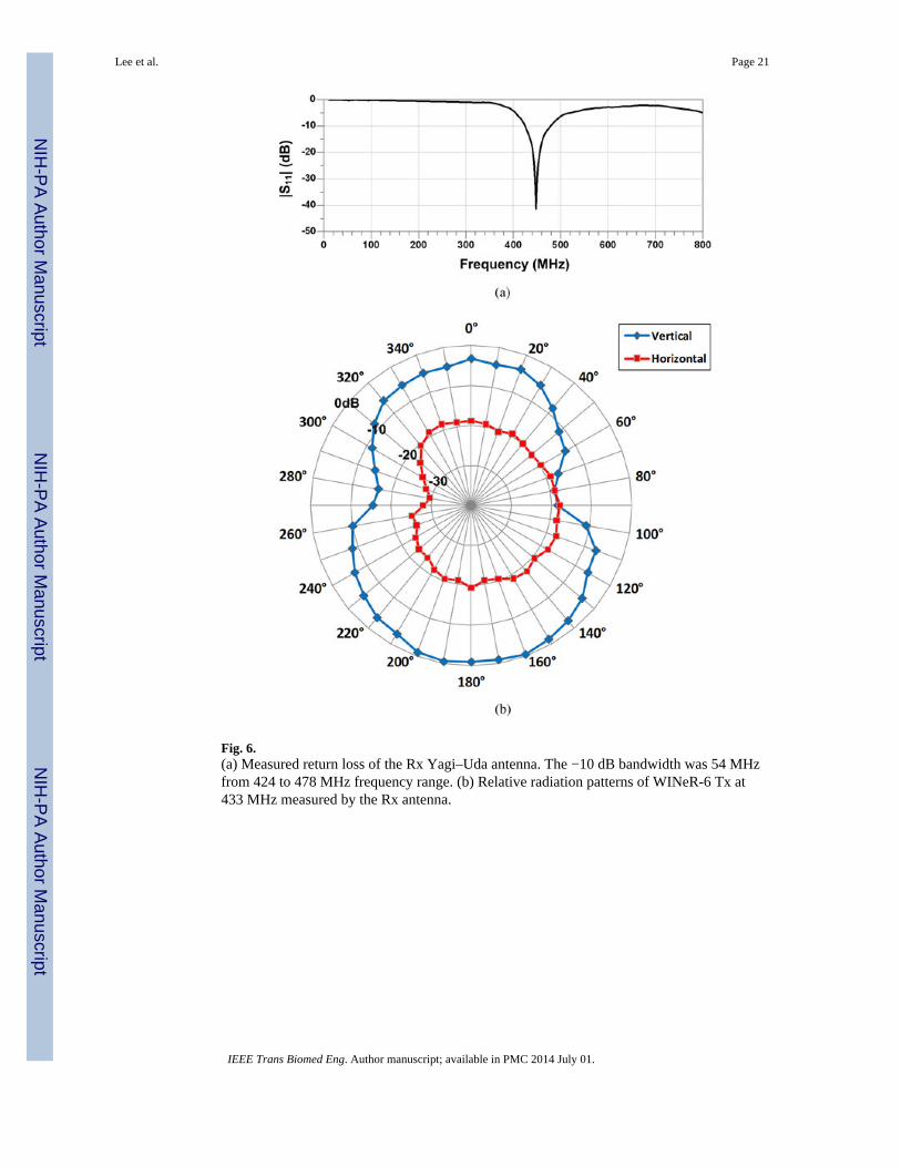
Fig. 6.(a) Measured return loss of the Rx Yagi–Uda antenna. The −10 dB bandwidth was 54 MHzfrom 424 to 478 MHz frequency range. (b) Relative radiation patterns of WINeR-6 Tx at433 MHz measured by the Rx antenna.
Lee et al. Page 21
IEEE Trans Biomed Eng. Author manuscript; available in PMC 2014 July 01.
NIH
-PA Author Manuscript
NIH
-PA Author Manuscript
NIH
-PA Author Manuscript

Fig. 7.Measured return loss and gain of the RF front end (RF module).
Lee et al. Page 22
IEEE Trans Biomed Eng. Author manuscript; available in PMC 2014 July 01.
NIH
-PA Author Manuscript
NIH
-PA Author Manuscript
NIH
-PA Author Manuscript
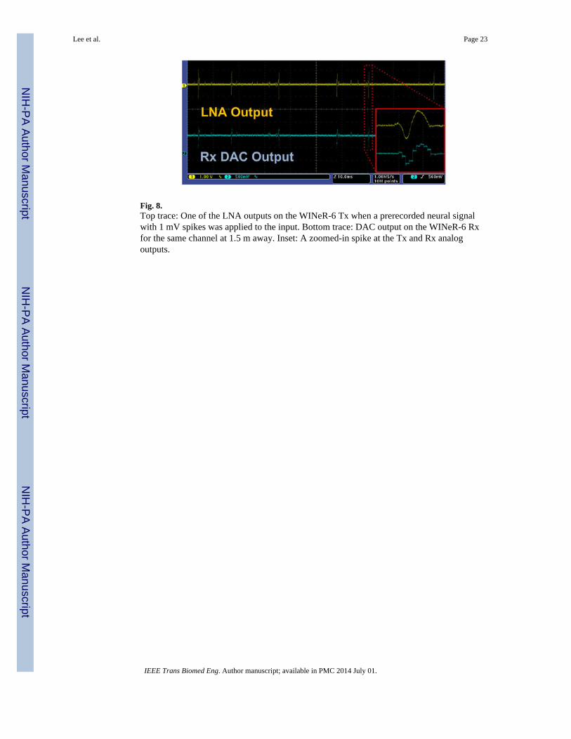
Fig. 8.Top trace: One of the LNA outputs on the WINeR-6 Tx when a prerecorded neural signalwith 1 mV spikes was applied to the input. Bottom trace: DAC output on the WINeR-6 Rxfor the same channel at 1.5 m away. Inset: A zoomed-in spike at the Tx and Rx analogoutputs.
Lee et al. Page 23
IEEE Trans Biomed Eng. Author manuscript; available in PMC 2014 July 01.
NIH
-PA Author Manuscript
NIH
-PA Author Manuscript
NIH
-PA Author Manuscript
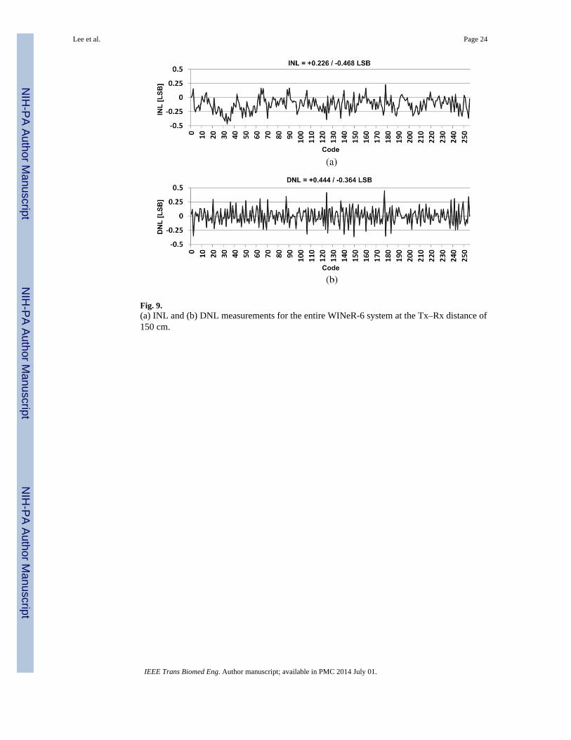
Fig. 9.(a) INL and (b) DNL measurements for the entire WINeR-6 system at the Tx–Rx distance of150 cm.
Lee et al. Page 24
IEEE Trans Biomed Eng. Author manuscript; available in PMC 2014 July 01.
NIH
-PA Author Manuscript
NIH
-PA Author Manuscript
NIH
-PA Author Manuscript

Fig. 10.Tone test measurements of the WINeR-6 system (a) without wireless link, (b) at the Tx–Rxdistance of 150 cm.
Lee et al. Page 25
IEEE Trans Biomed Eng. Author manuscript; available in PMC 2014 July 01.
NIH
-PA Author Manuscript
NIH
-PA Author Manuscript
NIH
-PA Author Manuscript

Fig. 11.Various noise measurement configurations to find out the contribution of each majorWINeR-6 component to the total system noise: (a) TDC noise measured by connecting aprecise function generator, (b) ATC + TDC noise without wireless link, (c) LNA + ATC +TDC noise without wireless link, (d) noise of the entire system.
Lee et al. Page 26
IEEE Trans Biomed Eng. Author manuscript; available in PMC 2014 July 01.
NIH
-PA Author Manuscript
NIH
-PA Author Manuscript
NIH
-PA Author Manuscript
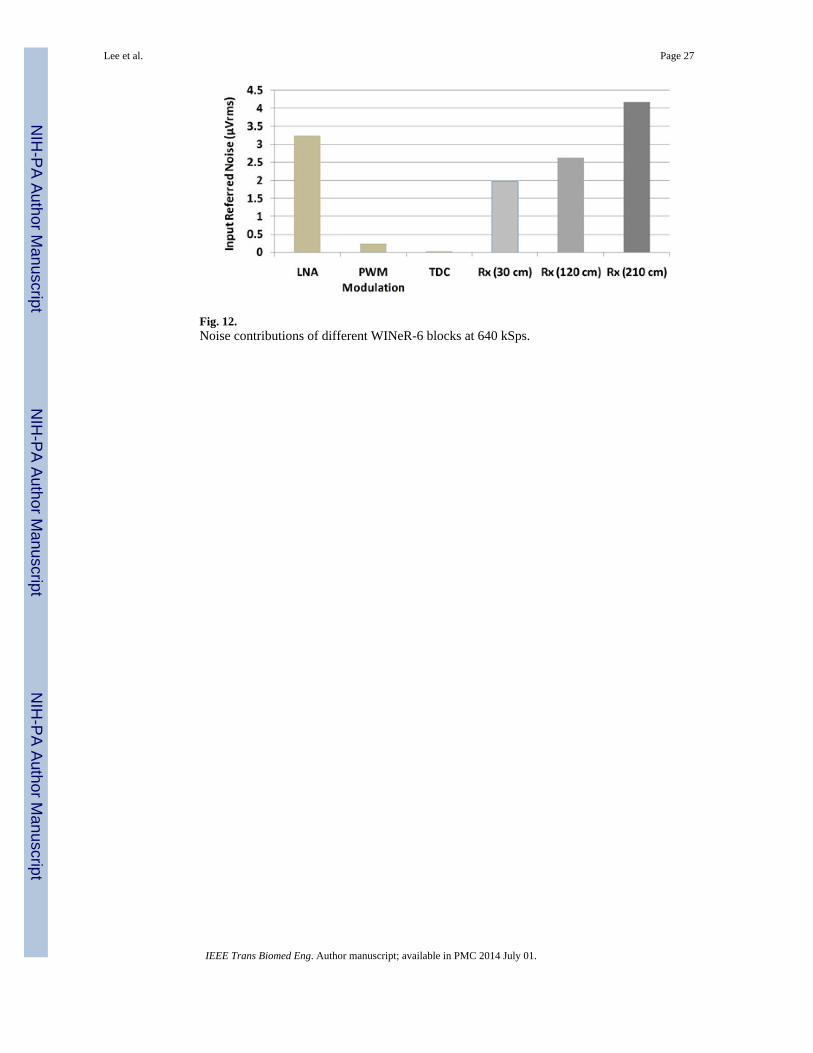
Fig. 12.Noise contributions of different WINeR-6 blocks at 640 kSps.
Lee et al. Page 27
IEEE Trans Biomed Eng. Author manuscript; available in PMC 2014 July 01.
NIH
-PA Author Manuscript
NIH
-PA Author Manuscript
NIH
-PA Author Manuscript
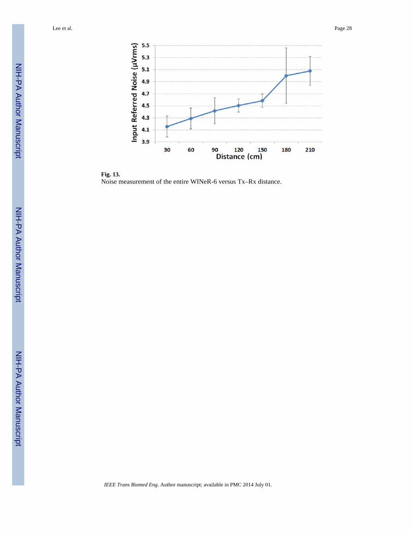
Fig. 13.Noise measurement of the entire WINeR-6 versus Tx–Rx distance.
Lee et al. Page 28
IEEE Trans Biomed Eng. Author manuscript; available in PMC 2014 July 01.
NIH
-PA Author Manuscript
NIH
-PA Author Manuscript
NIH
-PA Author Manuscript

Fig. 14.Awake freely behaving animal experimental setup. The rat completed two sets of 40 laps ona circular track with ~1 m in outer diameter, while we recorded neural signalssimultaneously from 32 channels using WINeR-6 and a hardwired setup. Quality of therecorded neural signals was observed in real time but single unit activities were classifiedoffline and used to construct the place fields in each case after synchronizing and combiningthe neural activity with the animal position from the recorded video.
Lee et al. Page 29
IEEE Trans Biomed Eng. Author manuscript; available in PMC 2014 July 01.
NIH
-PA Author Manuscript
NIH
-PA Author Manuscript
NIH
-PA Author Manuscript
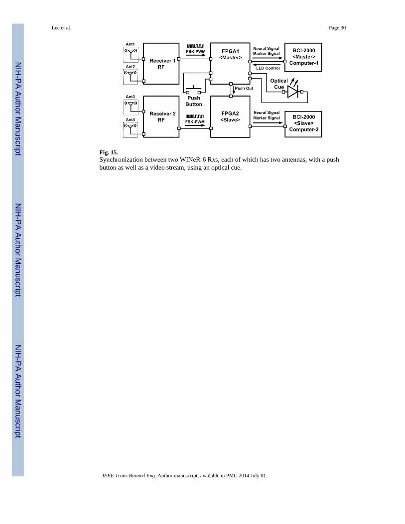
Fig. 15.Synchronization between two WINeR-6 Rxs, each of which has two antennas, with a pushbutton as well as a video stream, using an optical cue.
Lee et al. Page 30
IEEE Trans Biomed Eng. Author manuscript; available in PMC 2014 July 01.
NIH
-PA Author Manuscript
NIH
-PA Author Manuscript
NIH
-PA Author Manuscript

Fig. 16.Time-domain representation of 32-ch recorded signals in real time using the BCI-2000 GUI.
Lee et al. Page 31
IEEE Trans Biomed Eng. Author manuscript; available in PMC 2014 July 01.
NIH
-PA Author Manuscript
NIH
-PA Author Manuscript
NIH
-PA Author Manuscript
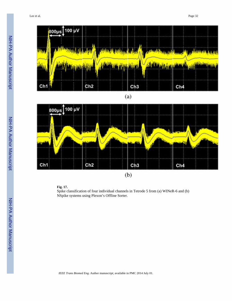
Fig. 17.Spike classification of four individual channels in Tetrode 5 from (a) WINeR-6 and (b)NSpike systems using Plexon’s Offline Sorter.
Lee et al. Page 32
IEEE Trans Biomed Eng. Author manuscript; available in PMC 2014 July 01.
NIH
-PA Author Manuscript
NIH
-PA Author Manuscript
NIH
-PA Author Manuscript

Fig. 18.Comparison between place fields resulted from (a) WINeR-6 wireless and (b) NSpikehardwired recordings.
Lee et al. Page 33
IEEE Trans Biomed Eng. Author manuscript; available in PMC 2014 July 01.
NIH
-PA Author Manuscript
NIH
-PA Author Manuscript
NIH
-PA Author Manuscript

NIH
-PA Author Manuscript
NIH
-PA Author Manuscript
NIH
-PA Author Manuscript
Lee et al. Page 34
TABLE I
Summary of the WINeR-6 System Specifications
WINeR-6 Tx ASIC [27]
Fabrication technology 0.5-μm Std. CMOS
Number of channels 32 + 4 feedback
Die size (mm2) 4.93 × 3.33
Supply voltage (V) ±1.5
Total power consumption at −14 dBm RF output power (mW) 15
Sampling rate from all channels (kSps) 58–709
FSK carrier frequency (MHz) 428/441
WINeR-6 Rx
Supply voltage (V) ±5
Current consumption (mA) 290 (+5 V), 80 (−5 V)
Size (cm3) 17.9 × 17.5 × 7.6
Bandwidth (MHz) 18
Center frequency (MHz) 433 MHz
Sensitivity (dBm) −65
Tuning range (MHz) 28(419–447)
Nominal Tx-Rx antenna distance (m) 1.5
Max. Tx-Rx antenna distance (m) 4.2
Neural Recording
Sampling rate/ch (kSps) 1.6–19.7
LNA gain (dB) 67.8/78
LNA input referred noise (μVrms) (BW: 200 Hz-8 kHz) 3.25
System input referred noise (μVrms) (BW: 200 Hz-8 kHz, Distance: 1.5 m) 4.58
System resolution (ENOB) 8
Computer interface USB 2.0 (480 Mbps Max)
Graphical user interface (GUI) BCI-2000 (Open source)
IEEE Trans Biomed Eng. Author manuscript; available in PMC 2014 July 01.