wideband direction coupler for vswr-measurements on receiver systems
DESCRIPTION
.TRANSCRIPT
VHF COMMUNICATIONS 3/83
Michael Martin , OJ 7 VY
Extremely Low-Noise Preamplifiers requireLow-Loss Antenna Cables!
Wideband Directional Coupler forVSWR-Measurements on Receiver Systems
Th e use of GaAs-FET technology has broughta considerable increase in receiver sensllivitythat was thought Impossible several yearsago. Both bipolar transistors and GaAs-FETsnow oller noise figures of less than 1 dB . andthe laller even allow noise figures of less than0.5 dB to be achieved. This means that systemtemperatures 01 50 K 0:. -223°C are nowpossible using thls technology. which wereonly possible with cooled parametric ampliliers in the past. The following article is 10
discuss several special features 01 'he GaAsFET preamplifiers without which it is not possible to obtain the values given In the datasheets. Furthermore. a wideband directionalcoupler is to be described thaI allows VSWRmeasurements 10 be made on the input circuits ot receivers and preamplif iers in the Irequency range 012 to 1400 MHz.
1.GENERAL
A typrcal receive system compr ises a receiveantenna. a short piece of feeder cable betweenantenna and masthead preamplifier. a second .longer cabte 10 Ihe actu al recei ver The task ofthe antenna IS 10 receiv e as much ene rgy as pos sible This energy should be amplified withoutany deterioration up to the demodulatio n level;
trus IS obtained using spe ctal low-no ise pream plif iers at RF-Ievel.
2.NOISE
2.1. Thermal Noise
The rmal molecule movement causes noisewh ich len ds to blanket very low receive-signallevels The natural limit value is given by Ihenorse 01 rhe input Impedance or Ihe receiverwhich amounts 10 290 K at an ambient tempera ture ol l ?OC, This corresponds to a noise power of- 174 dBm per Hz of bandwidlh . In Ihe case of aconvennonai bandwidth of 2.4 kHz, ttus is equalto an input noise power of - 140 dBm . co rresponding \0 an input voltage 01 22 nV Into 50 Q Trusmeans that no sign als of less than 22 nV can bereceived . even when usmq an ideal noiselessreceiver thai IS conoecteo li sing a lossi ess cabl e10 Ihe antenn a, II the ca ndwidth is nOI 10 bedecreased ,
2.2 . Signal-Io-Noise Ratio (No ise FIgure NF)
The noise l iyure is used to define the qual ily 01an amplifier. Till S oe ' inn ron ind ica tes how muchthe slqn al-to-no rse rauo at the output 01 theamptilier has det ello' i31ed with respe ct \0 thai alrne ,npu t.
153
VHF COMMlJNICAT'ON S Jl8 3
The value a, should be measured with anaccuracy 01 ± O05 dB.
II will be seen thaI the higher Ihe prearnplil ical ion. the less will be the contnbut ion of the se·cond stage 10(he overall norse lIg ure Fro!
2 .5. Measuring the Noise Figure
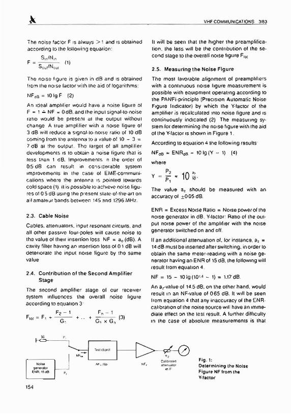
The mOSI tavorabte al ignmenl of preamp hlie rswith a conu nuous no ise ligure measurernent isposs ible wil h equipment opera1tng according tothe PANFI·pr inc ipl e (PreCISion Automatic NoiseFIgure Ind icator ) by wh ich Ihe Y·taclor of theampliller is recatcutated mto noise figure and IScontinuously indIcated (2) The measuung sy.stem for determining Ihe no ise "gure with the aidof the V-factor IS shown in Figure 1_
According to equat ion 4 the (ollowing rssons
NF"B = ENR"s - IOlg(Y - 1) (4)
The noise tac tor F IS alwa ys > 1 and ISobtainedacco rcm q 10the lollowing equation:
S,nIN,nF = ( I)
SoutINo. ,
The norse figu re is given in dB and IS obtain edIrom the norse lactor w ith tne aid of logarithms:
NFdB = 1019 F (2)
An ioeat amp hlier would have a noise ligure 01F = 1 ~ NF ; 0 ClB. and the inpu l siq nal-to-noiserauo would be pres ent at Ihe outpu t wlthou:chang e A Hue arnplllie r with a norse ligure of:I dB will reduce a siqnat-to-norse ralio of 10 dBcomin g from the antenna to a value or 10 - 3 =7 dB al the outpu t. The larget 01 all ampl ilierdevelopments IS 10 obtain a no ise Iigure that isless than I dB. Improvements 'n the order of0.5 dB ca n resul t in considerable system«norovernerus in Ihe case of EME·communi·ca nons where the antenna IS po inreo toward scold space (11 . II is po ssible 10 ach ieve no ise ligu·res 0105 dB usmq the present stare-ot-the -an onail amat eur band s between 145 and 1296 MHz_
where
P2Y = P, 10 ~ .
2.3. Cable Noise
2.4. Contribution of the Second Ampl ifierStage
Cabtes. atten uarors, input resonant c ircuns . andall ornar passive lour-poles will caus e noise toth e value 01 (hell insertion loss NF = a, (dB). Acav ity filter haVing an Insert ion loss of 0 1 dB willceienorare Ihe input nois e ligure by the samevalue
ENA = Ex.cessNOise Ratio = NOise power of thenorse ge neralor in dB . Y·laclor : Rallo 01 the ou tput norse power of the amplifier with Ihe no rsegenerator switched on and ofI.
If an addi tional auenuanon of. lor instance. a, =14dB must be inserted arterswitch ing . in order 10obtain the same meter·readlng with a noise generator having an ENR of 15 dB. me following willresult hom equauen 4.
NF = 15 - 10 Ig (10'.4 - I) = 1.17 dB ,
An a, ·value 01 14.5 dB. on the other hand, wouldresult In an NF·value of 065 dB . II will be seenIrom equat ion 4 that any inaccuracy of the ENR calibrat ion of the noise source wil l have an Immediate effect on the rest resul t. A further difft cultyIn me case of abso tute measurements is that
cur recei vernoise ligure
The second ampliher sraqe 01system Influences Ihe overallaccording 10equation 3'
F2 - IFto, = F1 ... - -- ... .. +
G,
Noi~&
91!1n.eo l .t101
ENR.1 5006
NF..
,'Ilf=, . GpFig . 1:Determining the NoIseFigure "IF tram theV·'actor
t54
VHF COMMUNICATION S 3183
only very good calibration attenuator s allow areprod ucible accuracy of bett er than 0.1 dB.which is esp eciall y required when low noisefigures are to be mea sured.
3.CHARACTERISTICS OF ANTENNACABLES
All cables between rhe antenn a and the preamplifier posses s an insert ion loss that will derenorate the system norse figure by at least the valueof its inserti on loss. This is not only a function ofthe cable length . but is also dep end ent on Ihe impedance (Zopr = 7S n lor CATV). and the ierrninating resistance. The insertion loss is a min i-
mum when the impedance 01 the antenna corresponds to Ihe impedance Zo or tn e cable. andtrus to the Inpu t impedance Z,n 01 the preamp li fier
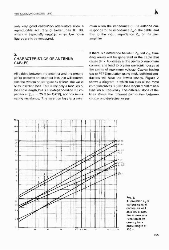
II there is a dilierence betw een Zo and Z,n. standmg waves will be generat ed In the cable thaicause (12 )( R)-Iosses al the pomts DI maximumC UI rem. and lead to grea ter c. electric los ses atthe points of maximum volraqe. Cable s havinggas or PTFE rnsulation using thick , polished conductors Will have the lowest losse s. Figure 2
shows a diagra m in which tne loss 01 Ihe mostcommon cab les is given lor a lenqth of 100 m as alunction 01 lrequ ency The dillerenl stope of theli nes shows the dillerc nt disrnburion betweencopper and dielectn c losses.
Fig , 2:Allenualion ao 01various coaxialcables. as wellas a 300 0 twtnline shown as atuncuon 01 trequency for acable tenglh of100m
155
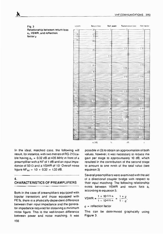
Flg.3Relallonshlp between return lossa' l VSWR, and rellecllontaerer Q
VHF COMMUNICATIONS 3/83
vsws, 0 ,--- - - 0; .,--- - -
l Cll t---- _otOJ )';~----f----·+----I-_l
\ os 30:
00 0 os--- 2S
---as
---010
ODs
---010'=015-
e = reuecuon lac tor
ThIS can be oererrnmeo graphically usingFigure 3.
possibte rn (3) to obtain an approxunat ion 01bOlhvalues, however. it was nec essary to reduce thegain per staqe to approximately 10 dB. wh ichresulted in the contr ibu tion of Ihe second stageto amount 10 one nin th 01 the iotat value (seeequanon 3)
Several preamplillers were exam ined wuh the aid01 a directional coupler b(ldge wun respect 10
the ir mpu t marchmq The following relationsh ipexisis between VSWR and return loss a,accordmq to equauon 5:
In the ideal . march ed case , the lollowing willresuu .Ior instance. WIth two met res ot RG·213 cable having 8 0 = 0.32 dB at 435 MHz In lront of 8
preamplifier wllh a NF of 1 dB and an rnpul irnpe dance of 50 Q and a VSWR of 1.0' Overall noisefigure NF I01 = 1.0 +- 0.32 -= 1.32dB.
4.CHARACTERISTICS OF PREAMPLIFIERS
BOlh in the case 01 preamplifiers equ ipped withbipolar transrsto rs and tnose eqmpped wilhFETs. there ISa pbysrcally-dependent dtlferencebetween the ir Input impedance and the generalor Impedance requrrad lor obtaining a minimumnoise figure. Trus is the well-known dil1erencebetween power and noise matchinq , II was
156
VSWR = 1 .. 10.0 05 0,
1 - ,0.cOSa,
1 +(>
1 - Q
VHF COMMUNICATIONS 3/83
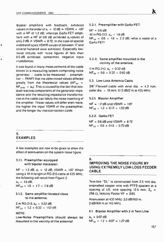
Bipolar amplif iers wilh feedback. exhibitedvalues In the order of at = 12dB ,;" VSWR = 1.67with a NF of 1.2 dB. whereas GaAs-FET amplifiers wllh a NF of 0.6 dB exbibneo a-values 01on ry 2 dB ,Q, VSWR ~ 8.72. In lhe case of spec ialwideband types VSWR·values of between 17 andseveral hundred were exnibited. Especially lownorse ci rcui ts with no ise ligures of less than0 5 dB exruoned. some times, neqative inpulrrnpeoances
II was found in ma ny measurements of the caoteloss es in a measuring system cornpnsinq no isegeneralor - cable to be measured - preamphlIer - PANFI thai the determined values dilleredgreally from the theorsucal value s (NF'OI ~
NFp,aa + <1<» This IS caused oy tne tactthat res idual reacnve components ot me genera~or Impe dance and the resu lling impedance rran storrnalion in Ihe cable can falsily the noise rnarchiop ofthe amplifier These values will drtter even more,the higher the Input VSWR of Ihe preamplifier,and the longer Ihe «uerconnecuon cable.
5.EXAMPLES
A few examples are now 10 be given 10 show IheeHecr 01attenuation on the system norse Ilgure.
5.1.1. Preamplilier equippedwilh bipolar translstor:
NF = 1.2 dB, a, = 12 dB. VSWR = 167 WhenUSinga 10 m lenglh of AG·213 cable at 435 MHz.the following Will result Irom Figure 2,ao ~ 16 dB :NF\o\ ~ 1.6 + 1 2 ~ 2 8 dB
5.1.2. Same amplifier located closeto t he antenna.
2 m RG-213. ao = 0.32 d8,NFIOI = 1.2 ... 0.32 = 152 dB
NOTE:Low-Noise Preamplif iers should always bemounted In the vicinity olthe antenna]
5.2 .1. Preamplilier w lth GaAs-FET:
NF ~ 06dBto m RG·213 21o = \6 dBNFror = 0,6 + 1.6 = 2 2 dB : wha t a waste of aGaA s-FET !
5.2.2. Same amplilier mounled in thevicinity ot the antenna:
2 m RG·213. 21 0 ~ 032 dBNF,Ol = 06 -I- 032 = 092 dB
5.3. Low-Loss Antenna Cable
3/8···Fle xwell cable with mner dia . = 4.2 mm ,outer dia . ~ 16 mm : 0,13dB/2 mat 435 MHz
5.3.1. Bipolar Amplifier
NF = 1,2dBandVSWR ~ 167NF,ol ~ 1.2 -I- 0.13 = 1.33 dB
5.3.2. GlIAs-FET
NF ~ 0.5dB and VSWR ~ 872NFror = 0,6 + 013 = 073d8
6.IMPROVING THE NOISE FIGURE BYUSING EXTREMELY lOW-LOSS FEEDERCABLE
TWIO-line "OL" is constructeo trom 25 mm era,enamelled copper wire with PTFE-spacers at aspacing of )./2. wire spacing 12.5 mm. Zo ~
298 Q, Velocity Faclor VF = 0.95.
Attenuation at 435 MHz : 3.3 dB/l00 rn,2 dB/l00 m al 145 MHz .
6.1. Bipolar Amplifier w ith 2 m Tw/n Line
30 = 0.07dBNFror = 12 -I- 0.07 = 1.27 dB
157
6.2. GaAs·FET Preamplifierwith 2 m Twin Line
aD~ 007 dBNF{D1 ; 06 + 0.07 = 0.67 dB. which correspo nds10a very low NF deter ioration'
RESULT:The high·impedance. low-loss tWin line is verysuited 10the hlqh -rmpeuance Input of the GaA sFET preamplifier!NF = 0.6 dB ,;" 43 K noise temperatu re, NF0.676 ~ 49 K
NOTE:In order \0 keep the ettects of di1ferlng cablelength In the system no ise figure as low as pos sible, Ihe intermediate cable should be as snortand as low-loss as oossot e An exact solutio n ;5only possote by alcgni ng Ihe preamplif ier i '1 conJunction wilh Ihe an tenna and int erconoecnnqcable by inject ing a keyed noise power, usirlg asecond antenna , mto th e rec eive system andalignmg it for minimum norse figure on th ePANFI.
smce trus is very exte nsive, and is usually notpossible at most amat eur s' loca tions. it canusually only be earned OUI in Ihe " laboratory":The generator Impedance which the antennaoffers to me preamplifier at the end of Ihe reede rcable must be measured and the amount andphase must be simulated with 1:1C aid of a stu bluner between norse generator and preamp lifi erduring the alignment for rmrurnum noise figure ,
A minimum noise figure auqnrneru made in theiaboratorv In conjunction with a no ise gen eratorImpedance 01500 Q ±0 5 o ~ a, ~ 40 dB IS onlyreproduclble In practice if the antenna exrubitsme same -mpecance'
Amateur antennas. on the orner nand. somelimes have a, values between 10 and 20 dB,which means Ihal the results remain somewhatuncertain.
158
VHF COMMUNICATIONS 3/83
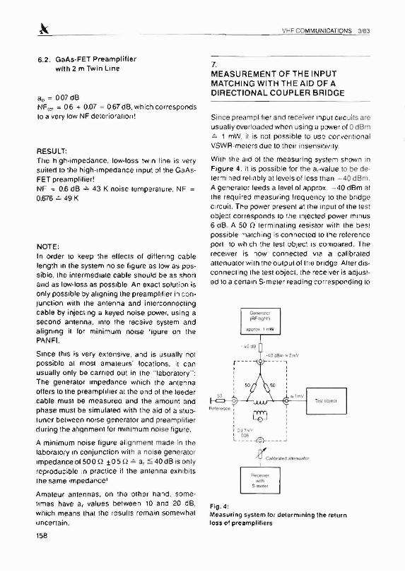
7.MEASUREMENT OF THE INPUTMATCHING WITH THE AID OF ADIRECTIONAL COUPLER BRIDGE
Since p rearnphtier and receiver InPUt Circuits areusually overloaded whe n using a power 010 dBm~ , mW, il is not possible 10 us e conventiona lVSWR-meters du e 10their insensitivuy,
Wit h the aid of the measuring system shown InFIgure 4, it is possible for the a-vatue to be de ter rnined rel rabt v at levels of less than - 40 dB m ,A genera tor feeds a level 01 approx. - 40 dBm alme requ ired measuring freque ncy to the brid gec rrcuit. The power present at lhe input of the testobject corresponds 10 the Injected power min us6 dB. A 50 n rermlnauno resistor wi th Ihe bes tpos sib le " l atch ing is co nnec ted 10Ihe referenceport to whi ch the lest object is compared . Therece iver is now con nected v ia a cal ibratedauenuaror wi tn tne o utput of tne ondqe Aller disconnect inq Ihe test object. [he receiver is adju sl'eo 10a cerram S·m erer reading corr esponding to
- 4 ~8
-<.Od8 11' .. i rn'':
Fig .4 :Measuring system lo r determining Ihe returnloss 01 preamplillers
VHF COMMUNICATIONS Ji83
approx imately 60 dB with the ala ot lhe calibratedauenuator If an identical rerrrunannq resistor IS
now connected to Ihe test object port , the reoucnon 01 the s -rnerer reaaing corresponos to thedirectional response of the budge Trus shouldDe grealer than 30 dB. If possible. when lowVSWR-values are to be measured. After connectlng the iest object. the reouct ion of the s-rnsierreading is oirecuy proportional to me a,-value IndB. il the S·meter IS also cahorared in dB. Withthe aid of the calibrated auenuator, a suosuun tonmeasurement can be carried out by measuringth is ausnuarlco and reading it 011 On theauenoator.
II IS Ihen possible with the aid of equation 5 orFigure 3 to deterrnine the VSWR . In order to beable to establish the overall system norse figurewhen using dillering preamphtrsrs and cables, ilIS necessary for the mput reuecnon values to beobtamso from lhe manufacturer of the preampliliers. A detailed description of further measurements that can be carried out with the aid of thebndge are 10 be found In (4)
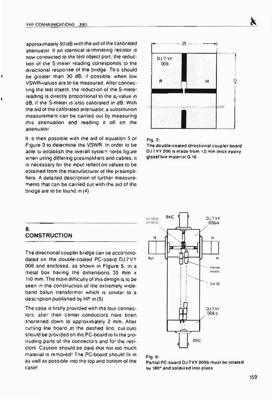
8.CONSTRUCTION
The elireClional coupler bUdge can be accommodated on the couote-coatec PC·board DJ 7VY006 and enclosed. as shown 10 Figure 5. in ametal box navinq the dimensions 35 mm x110 mm . The main dlfflcully ol ttus design IS10 beseen In 'he consrrucnon of the extremely wideband balun Iransformer which IS similar to acescnouon pubtisbed by HP In (5)
The case is flrslly provided with the four connectors. aher their center conoucrors nave beenshortened down 10 approximately 2 mm. Alter
cutting Ihe board at rhe dashed line , CUI-outsShould be provided on the PC-board 10 tn rhe protruding parts of the connectors and for Ihe resi·stors caunon snouto be paid that not lao muchrnaiertat is removed ! The PC·board should Iii inas well as possible mto the tOP ana oouorn of Ihecase!
35 - - ------j
OJ 7 VY
1006
R M 0-s
Flg .5:The double-coaled directional coupler boardOJ7VY 006 is mane lrom 1.5mm "lick epoxyglassfibre malerial G 10
OJ 7 VV0060
r--~?---../
OJ7VY006 b
/
/
BNC
Flg .6:Partial PC-board OJ 7VY 006b must be rotatenby 180· and soldered InlO place
159

The (WQ parrs of the board are nowsoldered 101 0
place as shown in Figure 6 by firstly solderingthe str ipline con nections alter wh Ich Ihe groundsu rface is soldered The four 10,.0 resistors th ai
lorrn rne rnp u t res istors are now soldered in to
place at Ihe tocauon ol the cutout , and an approxirnatetv 90 mrn length of SM 50 PTFE cabl e issoldered 10 Ihe ou tpu t stripune. Place as manyterrue beads onto the cable unl it approximal ely7 01 01 spacing remain s 10 the balan ced center
VHF COMMUNICATIONS J/83
point. The inner conductor 01 Ihe cable IS connected 10 the reference striphne, and the outerconoucror IS coonecieo 10 Ihe measunng poristripnne, A copper wire 01 0.8 0101 crarneier IS alsoprovided wilh terrue beads and is soldered lntoplace between ground and Ihe reference line.The territe beads should be glued as shown inIh e prototype, uSing a normal adhesive so thatIhe last 7 rnrn rem ain free. trnoor taru - The balunshould run as horizontal as POSSible to tne
t60
Fig. 7:Photograph ot theaurhors prototype,seen as Fig . 6
Fig. 6;Pholograph or theauthor 's prototypeIrom Ihe other sIde
VHF COMMUNICATIONS 3183
balanced point 01th e bridge ' This IS shown moreclearly Ihan in the lexl in the photographs 01 theaut hor s pro totype Figures 7 and B show thattwo pieces 01 51 Ii res istors have been iostalledinstead of the lou r piece s of 100 Ii
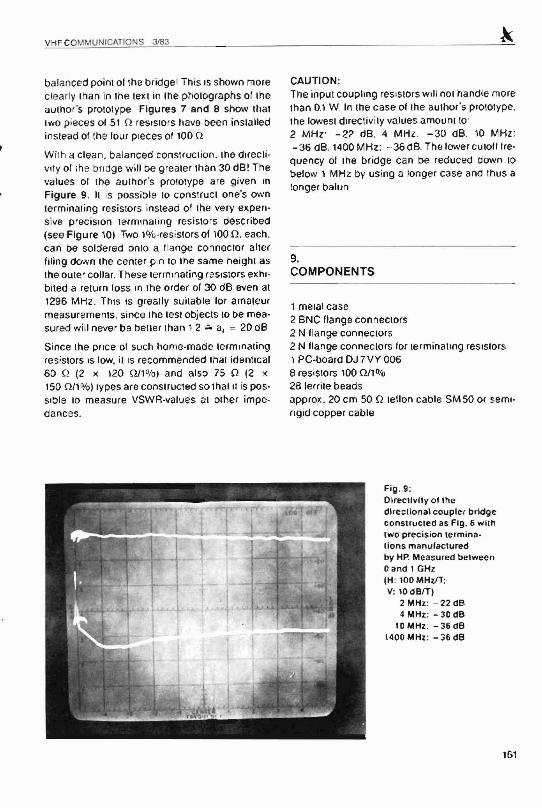
W irh a clean. balanced construction. me crre cuvlty or rhe bridge wi ll be g realer than 30 dB! Thevalu es 01 the author's prototype are given mFigure 9. II is possible 10 construct one's ownterrn inat inq resistors instead of Ihe very expensive prec ision termrnaling resisto rs described(see Figu re 10) Two Wo-res istors 01100 Q , each ,can be soldered onto a flange connector alterfiling down lhe center pin 10 lhe same height asIhe outer collar, These terrrunatinq resistors exrubueo a return loss In the order of 30 dB even at1296 MHz . This IS greatly suitable lor amateurmeasurements, since Ihe rest objects 10 be rnsasured will never be better than 1 2 .;0 a, = 20 dB
Since Ihe price of such hom e-rnaoe terrnmatinqresi stors IS low. it IS recommended Ihal identical60 o (2 x \20 illl%) and also 75 Ii (2 x150 011%) ivpes are constructed so tna t u is posSible 10 measu re VSWA·values al other impedances.
CAUTION:The input coupling resistors Will not handle mo rethan 0.1 W. In the c ase of the author 's pro totype.the towest directivity values arnount to:2 MHz.' -22 dB, 4 MH z. -30 dB . 10 MHz :-36 ea.1400 MHz.: - 36 dB . Th e lower cuion rrequency 01 Ihe bridge can be reduced down 10
below 1 MHz. by using a long er case and thus alonger balun
9,COMPONENTS
1 metal case2 BNC flange connectors2 N Ilange connectors2 N flange connectors lor terrninaunq resistors1 PC·board OJ 7 VY 0068 resistors 100 illl0f028 lerrite beadsapprox. 20 em 50 Q ieuon cable SM 50 or semi'rigid copper cable
Fig . 9:Dlrecllvlly 01 th edl rec llonal coupler bridgeconstructed as Fi g . 6 w ith(Wo prec ision termina lions manu facturedby HP. Measured betweenoand I GHz(H: 100MHzfT:V: 10dB/l)
2 MHz : -22 dB4 MHz : - 30 dB
10MHz: - 36dB\400 MHz : - 36 dB
101
VHF COMMUNICATIONS 3/83
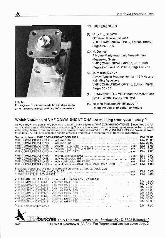
FIg . 10:Photograph ot a nerne-made termination uSIngan N.llange connecter and two 100 U resisters
10. REFERENCES
(1) R Lentz . DL3WR :Noise in Receive SystemsVHF COMMUNICATIONS 7, Edilion 4/1975.
Pages 217 - 235
(2) M .Dohlus
A Home-Mace Automat ic Noise-FrqureMeasuring SystemVHF COMMUNICATIONS 15. Ed. 1/1983.
Pages 2 -11 and Ed. 2/1983, Pages 66-83
(3) M . Marun. OJ 7 VY,A New Type 01Prearnphher for 145 MHz. and435 MHz. ReceiversVHF COMMUNICATIONS 10. Edllion 1/1978.
Pages 30-36
(4) R. Waxwe iler, OJ 7VD: Impedanz.-MeBbrucke
CQ·DL 7/1982. Pages 328- 331
(5) Hewlell Packard : AN 86. page 11U sing lhe Vector Impedance Meters
OM 3.00OM 3.00
OM 3800OM 40 .00DM 42.00OM 44 .00OM 46 00OM 5000OM 53 00OM 58 .00
DM 8 00
.... ... eacheach
Which Volumes of VHF COMMUNICATIONS are missing from your library?As you know, the puousners con unue 10 reprint back copies of VH F COMMUNICATIONS Srnce rhey are lulltechnical ancios and IIHle news or advernsmq , they contam a great de i'll 01non·agmg mtormanon ina: ISluSIasvalid today, Manyol our reade rs Will also have lent out cop ies of VHF COMMUNICATIONS and never rece.vecthem back. All ed itions avaitabte can be obt ained 11 0 m your I op resentan ve o r 110m 1 113 publishers.
Subscrlpllon to VHF COMMUNICATIONS 1963 OM 22 .00VHF COMMU NICATIO NS - Vo lume t 982 DM 2000VHF CO MMU NICATIO NS - Volume 1981 OM 20 00VHF COMMUNICA TIO NS - VOlume 1979/1980 each DM 18.00VHF COMMUNICAT IONS - Volume 1976.1 977 . and 1978 ,.. ... each OM 16.00VHF CO MMUN ICATIONS - Vo lume 974. 1975 ' " .. eacn OM 14 00
VHF CO MMUNICATIONS - Individu al copies 1982 . . each DM 600VHF COM MUN ICAT IONS - Individ ual cop ies 198 1 eac h OM 5.50VHF COMMUN ICATIONS - Individual copies 197911980................ . each OM 4.50VH F COMMUNICATIONS - Individual co pies 1974 , 1975. 1976 1977,1 978 each OM 400
InOlv,dual cop ies out of elde r, Incomplete volumes. CI S long as sloe" lasts1/ 1970, 2/ 970. 3!1970 . 21197 1, 31 971 ..1. 1972. 2.'1 972. 211973. 4 /1973 ..
VHF COMMUNICATIONS - Discount price lOT any J volumes :VHF CO MMUNICATIONS . Volumes 1974- 1976VHF CO MMUNICA TIONS Volumes 1975 - 1977VHF CO MMUNICAT IO NS - Volumes 1976- 1978VH F COMMUNICAT IO NS - Volumes 9 77- 1979 .VH F COMMUNICAT IO NS - Volumes 1978- 1980VH F COMMUNICATIO NS - Volumes 1979- 198 1VHF COM MU ICATIONS - Volumes 1980-1982VHF COMMUNIC ATIONS - Vol ume s 198 1-1 983
Plastic bin ce r for 3 volumes
Lr m0 n r.~~J..4,.,.~ <.},.\f''J'JI:·!vcr I\,lllf::: Terry O. Billan . Jahnslr. 14 . Postfach 80 . 0-8523 Baiersdorf16 2 Tel. Wesl Germany 9133-855. For Represemalives see cover page 2