a review on evaluation of the deformations · pdf file · 2015-04-10thermal effects...
TRANSCRIPT

115
Int. J. Mech. Eng. & Rob. Res. 2014 Jitesh A Ingale et al., 2014
ISSN 2278 – 0149 www.ijmerr.com
Vol. 3, No. 3, July, 2014
© 2014 IJMERR. All Rights Reserved
Review Article
A REVIEW ON EVALUATION OF THE DEFORMATIONSINDUCED BY SOLAR RADIATIONS ON SOLAR PANEL FRAME
Jitesh A Ingale1*, V H Patil1 and A A Patil1
*Corresponding Author: Jitesh A Ingale � [email protected]
Thermal effects on structure of solar panels exposed to solar radiation are significant andcomplicated. Furthermore, the temperature variation within a year may result in damage inframe structures with covering glass considering the solar radiation. The aim of the presentpaper is to evaluate deformation state due to temperature on photovoltaic modules surface.Laboratory measurements were carried out employing single grid strain gauges, in order todetermine stress in significant points of four different samples subjected to temperature variations.Finally results were analyzed and compared, in order to characterize the performances expectedfrom photovoltaic panels and to prevent cell breaking.
Keywords: Evaluation, Solar Panel, Strain Gauges, Thermal Deformation
INTRODUCTION
With the gradual depletion of fossil fuels inour planet, the application of solar energybecomes very popular currently in the world.Solar energy can be directly utilized througha variety of devices such as solar collectorsor photovoltaic cells as shown in Figure 1.
Solar cell is one of the crucial componentsinphotovoltaic systems. At present, substratecrystalline silicon solar cells with clear coverglasses are widely used in photovoltaicsystems. The solar panels are made ofsemiconducting materials including monocrystalline silicon, polycrystalline silicon and
1 Department of Mechanical Engineering, GF’s Godavari C.O. Engineering, Jalgaon, India.
gallium arsenide. The high transmittanceglass cover is pressed together withthe panelthrough silicone rubber, which provides astrongprotection for the core solar cells.Thepanel consists of asupport frame, a backboard made from honeycomb sandwichmaterial, and solar cells installed on the backboard which are covered by glass fiber sheetFigure 2. The material of support frame andyoke is always different from the back board.
Evaluation of solar panel deformations ondifferent points, from the center to the edges,over the cells or the gaps, by the frame oralong the electrical connections, allows toidentify the most critical zones, which must
116
Int. J. Mech. Eng. & Rob. Res. 2014 Jitesh A Ingale et al., 2014
Figure 1: Solar Panel Set Up
Figure 2: Sectional View of Solar Panel
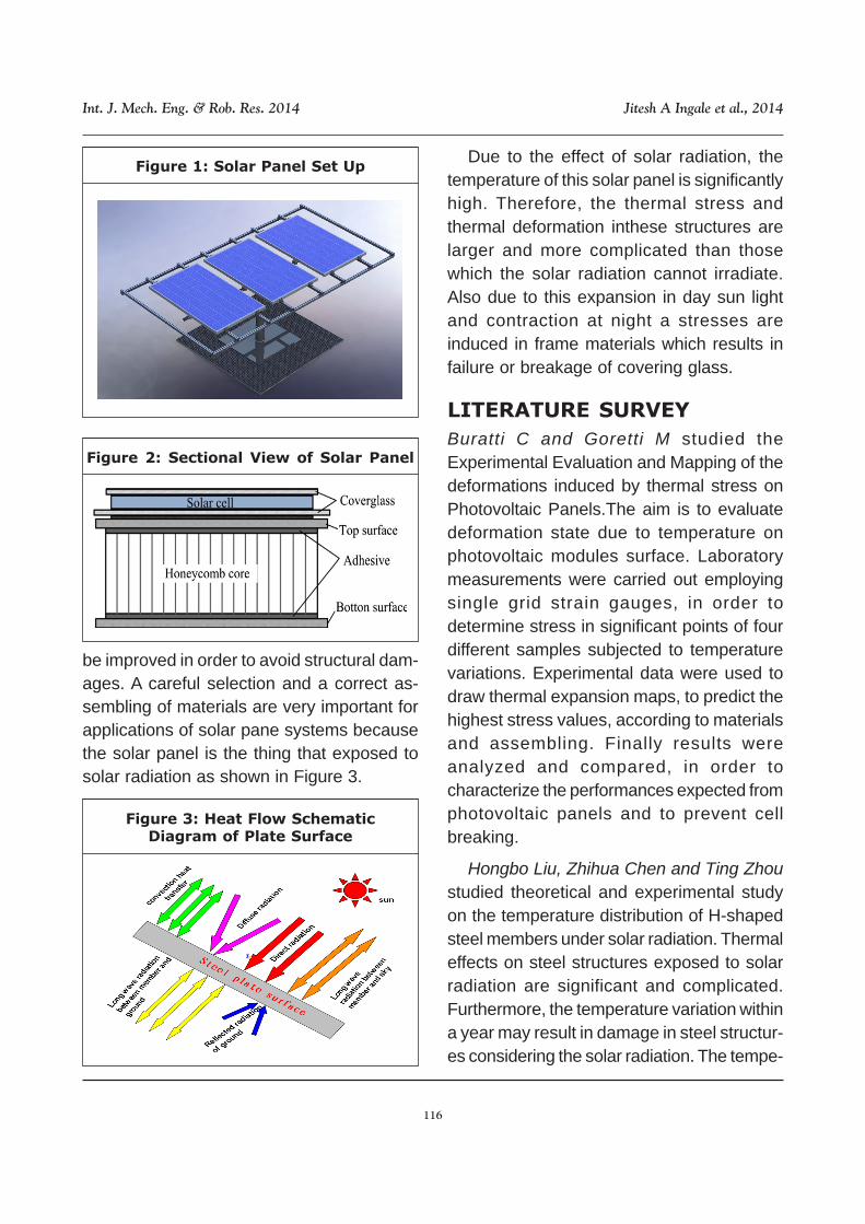
Figure 3: Heat Flow SchematicDiagram of Plate Surface
Due to the effect of solar radiation, thetemperature of this solar panel is significantlyhigh. Therefore, the thermal stress andthermal deformation inthese structures arelarger and more complicated than thosewhich the solar radiation cannot irradiate.Also due to this expansion in day sun lightand contraction at night a stresses areinduced in frame materials which results infailure or breakage of covering glass.
LITERATURE SURVEY
Buratti C and Goretti M studied theExperimental Evaluation and Mapping of thedeformations induced by thermal stress onPhotovoltaic Panels.The aim is to evaluatedeformation state due to temperature onphotovoltaic modules surface. Laboratorymeasurements were carried out employingsingle grid strain gauges, in order todetermine stress in significant points of fourdifferent samples subjected to temperaturevariations. Experimental data were used todraw thermal expansion maps, to predict thehighest stress values, according to materialsand assembling. Finally results wereanalyzed and compared, in order tocharacterize the performances expected fromphotovoltaic panels and to prevent cellbreaking.
Hongbo Liu, Zhihua Chen and Ting Zhoustudied theoretical and experimental studyon the temperature distribution of H-shapedsteel members under solar radiation. Thermaleffects on steel structures exposed to solarradiation are significant and complicated.Furthermore, the temperature variation withina year may result in damage in steel structur-es considering the solar radiation. The tempe-
be improved in order to avoid structural dam-ages. A careful selection and a correct as-sembling of materials are very important forapplications of solar pane systems becausethe solar panel is the thing that exposed tosolar radiation as shown in Figure 3.

117
Int. J. Mech. Eng. & Rob. Res. 2014 Jitesh A Ingale et al., 2014
rature distribution of H-shaped steel mem-bers was investigated through a systematicexperimental and theoretical study in the caseof solar radiation. First, an H-shaped steelspecimen was designed and its temperaturedistribution under solar radiation was obtain-ed by a test. After that, a numerical methodwas proposed to obtain the temperaturedistribution under solar radiation. This methodwas based on transient thermal analysis andthe analytical result was verified by the aboveexperimental result. Furthermore, a para-metric study was conducted to investigate theinfluence of various solar radiation para-meters and orientation of H-shaped steelmembers on the temperature distributionunder solar radiation. Finally, a simplifiedapproach was developed to predict thetemperature distribution under solar radiation.Both experimental and numerical resultsshowed that the solar radiation had asignificant effect on the temperaturedistribution of H-shaped steels. Consideringthe solar radiation, the temperature of thespecimen is about 20.6C higher than thesurrounding ambient air temperature. Thetemperature distribution under solar radiationwas observed to be sensitive to the steel solarradiation absorption and orientation, butinsensitive to the solar radiation reflectance.
Xiaoyan Wang, Hongbin Geng, Shiyu He,Y O Pokhyl, K V Koval studied the Effect ofthermal expansion coefficient on the stressdistribution in solar panel. Residual thermalstress, which affects structural safety, wouldbe produced in the solar panel under thetemperature field because of the multilayerstructure of the solar panel. The stress distri-bution and the effect of thermal expansioncoefficient on the stress of the solar panel
under the temperature field using analyticmethod were studied. The analytical resultsshowed that the maximum of structuraltensile/compression stress and shear stresspresent in the layer of polyimide film andsilicone rubber which bonded carbon fibercomposite and polyimide film, respectively.The maximal stress value in the structure wasdecreased remarkably by choosing to usepolyimide film with lower thermal expansioncoefficient. The one dimensional model usedin this work would exert an importantinfluence on the design and structuraloptimization of the solar panel.
E V Morozov, A V Lopatin studied a noveldesign of the composite structural latticeframe for the spacecraft solar arrays arepresented in the paper. The frame iscomposed of two flat lattice composite platesassembled into the three-dimensional panelusing frame-like connectors. Design,fabrication, modeling and modal analysis ofthe panel solar arrays based on the proposedtechnology are discussed. The lattice panelsare modeled as three-dimensional framestructures composed of beam elementssubjected to the tension/compression,bending and torsion using the specializedfinite-element model generator/designmodeler. Results of the calculations of thefrequencies and vibration forms for the latticepanels with various types of supports imitatingthe ways the panels can be attached to thespacecraft body, deployment must, andadjacent solar panels are presented anddiscussed. The lattice frame design formaximum fundamental frequency isperformed subject to constraints imposed onthe geometrical parameters of the solarpanel.

118
Int. J. Mech. Eng. & Rob. Res. 2014 Jitesh A Ingale et al., 2014
E V Morozov, A V Lopatin studied nonlinearanalysis of the deformation of a thin flexiblecomposite membrane stretched on arectangular cell of the spacecraft solar arrayframe is presented in the paper. The frameof the array and the thin flexible membranestretched on this frame are designed to becapable of withstanding the transversemechanical loadings exerted on the structureduring the delivery to orbit and deployment.The governing nonlinear equations modelingthe pre-stretched flexible orthotropicmembrane are solved using Galerkin method.Results of calculations are compared withthose based on finite-element modeling. Thecomparisons have demonstrated efficiencyof the proposed approach to the analysis anddesign of composite solar arrays featuringorthotropic composite flexible membranes.The parametric analyses were performed forvarious combinations of the g-force, mass ofthe photovoltaic elements and dimensions ofthe solar array.
THEORY
Solar arrays are critical appendages whichprovide primary power sources for space-craft. When the spacecraft is traveling aroundthe Earth, the solar arrays experience perio-dic heating and cooling in the sunlight andshadow region of the Earth with the variationof the thermal environment. Dramatic tempe-rature changes occur at day–night and night–day transitions in the orbit. Sudden heatingchanges on a surface of an appendage mayinduce temperature gradients that generatetime-dependent bending moments. Thesemoments induce the structure deformationsand vibrations of solar arrays, which influencethe energy efficiency and reliability of on-orbit
spacecraft. Therefore, thermal analysis ofsolar arrays is of great importance for thesafety operation of spacecraft. Much researchon the thermal analysis and thermal-structureresponse of solar array and other appen-dages has been carried out. Foster and Tin-ker compared the flight data and computersimulation results of the solar array for HubbleSpace Telescope, and pointed out that thesource of the disturbances was the thermallydriven deformation of the solar arrays inconjunction with frictional effects in the arraymechanisms. Thornton et al., have donemuch research on the Hub-ble Space Tele-scope solar array including coupled and un-coupled thermal-structure analysis of boomsand blankets. Johnston and Thornton studiedthe thermal-structural performance of rigidpanel solar arrays. Song et al. developed acomprehensive structural model of compositespacecraft booms and studied the thermally-induced flexural oscillations. Xue et al.,discussed the temperature field of thin-walledtube elements for transient thermal-structuralanalysis of large-scale space structuresbased on finite element method, andexpounded the necessary condition ofthermally-induced vibration and the criterionof thermal flutter. Yang et al., provided amethod to calculate the temperature respon-se of folded solar array. Li et al. performedthe characteristics of the transient tempe-rature field in the simplified rigid solar array.Foster and Aglietti focused on the thermalenvironment and the response of themultifunctional structures, the temperature ofthis structure was analyzed by developing anumerical model, and the possible thermalcontrol solutions were discussed either.However, the previous research focused on

119
Int. J. Mech. Eng. & Rob. Res. 2014 Jitesh A Ingale et al., 2014
the key components like beams or panels ofthe large space structures, but few discussedabout the temperature field of the whole solararray.
However, because the solar array is acomplicated space structure, includingpanels, beams and joints which have differentmaterial characteristics, the thermal exchan-ge and coupling among its components andthe space environment should be considered.The flight data indicated that the compositestructures of the solar array have remarkableinfluence on its temperature and deformation.Therefore, it is necessary to analyze thetransient temperature field of the whole solararray accurately. Nodal network method andfinite element method (FEM) are the mostcommon tools used for thermal analysis ofthe spacecraft and its appendages. Discretemathematics model and finite differencetechnique are used in nodal network methodto solve the temperature distribution. Thenodal network method has strongpracticability dealing with the thermalproblems, but it is difficult to solve thecomplex structures considering complicatedboundary conditions. In contrast, FEM hasmany advantages for the thermal analysis ofspace structures. For instance, the inter-polation technique considering physical pro-perties with the change of the temperaturecan be used to reveal more accurate resol-utions, and the structure model can becombined into the thermal analysis model tocalculate the temperature distribution. Athermal analysis model of a composite solararray with complex structures is developedto characterize the thermal response of thewhole solar array system subjected to spaceheat flux. First, the view factors of orbitingsolar array in low Earth orbit and geosynchro-
nous orbit are proposed according to its flightattitude based on the thermal environment.Then the thermal analysis model for the com-plex solar array is developed, in which theinfluence caused by honeycomb panel, sim-plified hinges, composite frames and yokesare involved. The transient temperature fieldsin different orbits of all the components arestudied by using the model. Furthermore, thethermal response of the solar array with twocommonly used materials is contrastiveanalyzed.
Thermal Environment of the Solar
Array
The orbiting spacecraft and its solar arraysmay be heated by space environment andmultiple heat sources. The Sun and Earth arethe primary heat sources. The main thermalenvironment of solar array includes: directsolar radiation, Earth-emitted radiation andEarth-reflected radiation. Meanwhile, thesolar array may be heated by other planets,or may have thermal exchange with themodule and other components of thespacecraft. But compared with the main heatsources, they are small enough to be ignored.Moreover, the solar array also emits heatradiation to deep space. The typical thermalenvironment of solar array is shown inFigure 4.
Figure 4: Thermal Exchange betweenSpacecraft (Solar Array) and Space

120
Int. J. Mech. Eng. & Rob. Res. 2014 Jitesh A Ingale et al., 2014
According to the mechanical structure of thesolar array, a distinguishing feature is thatthe attitude of solar arraycan be regarded astracking and catching the Sun irrespectiveofthe orbit inclination. So the normal of thesurface towards the sunlight is always paral-lel to the solar radiation vector. The thermalenvironment of the solar array in circular or-bit is shown in Figure 5.
Figure 5: Schematic of ThermalEnvironment of Solar Array in Orbit
Calculation of the External Heat Flux
and Effective Thermal Conductivity
External Heat Flux
The solar flux S is approximately 1353 W/m2. The solar flux received by a surface isgiven by
...(1)
Where
θ = the angle between the solar vector andthe normal of the surface.
αeff = is the effective solar absorptivity of theanodic surface of solar array.
For solar array, the angle θ equals to 0,αeff is determined by incident photon to-electric conversion efficiencies, packingfactor and solar absorptivity.
θα coseffs
Sq =
It is expressed as
...(2)
Where
ηw= the conversion efficiency.
ηp= the packing factor.
αsc= the solar absorptivity of the solar cellsurface.
αsb= the solar absorptivity of the surfacebetween the solar cells.
Effective Thermal Conductivity
The effective thermal conductivity is given bythe equation
...(3)
Considering the thermal environment of thesolar array, the heat exchange betweenspace and panels is more significant than thatbetween panels. So the gas thermalconductivity (kg) and the radiant effectiveconductivity (kr) are negligible. The effectivethermal conductivity is simplified to
...(4)
( ) ηηηαηαα pwpsbpsceff−−+= 1
kKKK rgfe A
A
A
A +⎟⎠
⎞⎜⎝
⎛ ∆−+∆= 1
KKK ffe l
t
A
A
3
32=∆=
Figure 6: The Thermal AnalysisModel of a Typical Solar Array

121
Int. J. Mech. Eng. & Rob. Res. 2014 Jitesh A Ingale et al., 2014
Substantial improvements in the design ofspace solar arrays have been made by intro-duction of the thin-film stiffened panels(FITSs).
Figure 7: Temperature Field of Framein Normal Thermal Environment
Thin film photovoltaic (TFPV) solar arraysoffer the potential for providing a higher levelof power generation in a lightweight configu-ration that can be compactly stowed for aspace launch. A typical solar wing design isshown in Figure 8.
Figure 8: Spacecraft with Solar Arrays
The frame of the array and the thin flexiblemembrane stretched on this frame should becapable of withstanding the mechanical load-ings exerted on the structure during the de-
livery to orbit and deployment. Advancedhigh-modulus, high-strength carbon fibre re-inforced polymers (CFRPs) are normallyimplemented in current designs. One of thetypical configurations of the solar array frameis assembled from the CFRP thin-walledtubes joined with the metal fittings-connec-tors (Figure 9).
Figure 9: Solar Array Frame
The thin flexible membrane is stretchedon the frame and fixed to the tubes. Thenthe photovoltaic cells are attached to the sur-face of the stretched membrane. In the mostof the designs, the deployable solar arraysare stowed folded and could be deployed invarious configurations. When stowed, theyare usually placed parallel to each other andcompactly packaged for launch. During thedelivery to orbit, the membranes are sub-jected to the transverse g-force. The result-ing pressure is equal to the product of theweight-per-unit-area of the membrane withthe photovoltaic elements attached by the g-force. As a result of this loading the flexiblemembrane deflects. The excessive deflectioncould lead to the damage of the photovoltaiccells and/or electrical circuits. For this rea-son, one of the design requirements is thatthe deflection of the membrane should be lim-ited to some specified value.

122
Int. J. Mech. Eng. & Rob. Res. 2014 Jitesh A Ingale et al., 2014
The design of the solar array implies thesolution of two interrelated problems. The firstone involves the strength and buckling analy-ses of the frame and normally requires theuse of a finite-element method. Based on theresults of these analyses, the parameters ofthe thin-walled CFRP tubular rods can befound. The second problem is related to theanalysis of the deformation of the flexiblemembrane stretched on the frame and sub-jected to the transverse load. The solution ofthis problem provides the geometric param-eters of the membrane and stretching forcesdelivering the allowable level of deflectionprescribed by the design specifications.Based on this information, the required num-ber of the internal tubular rods can be identi-fied. For given overall size of the frame, thedistances between these rods in the framecan be calculated. These dimensions and thevalues of pre-stretching membrane forcesneed to be used as part of the input data forthe design analysis (strength and buckling)in the first problem. Joint solution of theseproblems delivers the design of the solar ar-ray. The solution of the second problem re-lated to the non-linear deformation of the flex-ible membrane carrying photovoltaic ele-ments is presented in this paper. The prob-lem is formulated for the orthotropic flexiblemembrane subjected to the transverse uni-form pressure and tensile in-plane forcesapplied to the edges of the membrane. Thedeformation of the membrane is modelled bythe system of non-linear differential equa-tions. This system is reduced to the govern-ing system of three equations presented interms of the in-plane displacements and de-flection. The first studies of the non-lineardeformation of isotropic membranes under
transverse loading have been performed byFöppl and Föppl and Prescott. However, theydid not consider the in-plane pre-stretching.In this work, the solution of the governingsystem of non-linear differential equationshas been obtained using Galerkin method.The membrane in-plane displacements anddeflection were approximated by trigonomet-ric functions. Based on this approach, thealgebraic cubic equation with respect to thedeflection value at the centre of membranehas been obtained. Solution of this equationprovides an analytical formula for the calcu-lation of the membrane deflection at the cen-tral point. Using this formula, the calculationof the deflections have been performed forisotropic and orthotropic flexible membraneshaving different geometry parameters andsubjected to different levels of loads. Theresults have been verified using comparisonswith the finite element solutions.
Decay of solar panels depends not onlyon chemical action of pollution and atmo-spheric agents, but also on thermal stresscaused by solar radiation. Evaluation of pho-tovoltaic modules deformations on differentpoints, from the center to the edges, over thecells or the gaps, by the frame or along theelectrical connections, allows to identify themost critical zones, which must be improvedin order to avoid structural damages. A care-ful selection and a correct assembling of ma-terials are very important for applications ofphotovoltaic systems, such as their integra-tion in building components and noise barri-ers.
Due to the effect of solar radiation, the tem-perature of these solar panel structures issignificantly higher than the surrounding

123
Int. J. Mech. Eng. & Rob. Res. 2014 Jitesh A Ingale et al., 2014
ambient airtemperature in summer, and thetemperature difference between frame andambient air may exceed a value of 20°C. Inaddition, the temperature of frame structuresis non-uniform under solarradiation. If a framestructure is constructed in summer, its tem-perature change may exceed a value of 80°Cinwinter. For this temperature change, thethermal stress is induced in solar panel framestructure. Therefore, the panel willfail or frac-ture because of deformation considering thetemperature change in addition toother loads,such as gravity and wind load. Also defor-mation results in damage of covering glassas shown in Figure 10.
Figure 10: Damaged View of Covering Glass
METHODOLOGY
Proposed Methodology
Solar panels are subjected to thermal stressdue to solar radiation as shown in Figure 11,variable on different points of the module,which produces a particular deformationstate.
Figure 11: Damaged View of Covering Glass
In the present paper an experimentalevaluation of deformation state due to tempe-rature variations on photovoltaic panel'ssurface. Paper is a part of a work concerningthermal performances of photovoltaicmodules. In working conditions, photovoltaiccells are subjected to a thermal gradientbetween the two sides of the panel, due tosolar radiation. The aim of the present workis to prevent damaging of different compo-nents by identifying the most strained points.It consists in laboratory extensometric mea-surements on specimen's front side, the onedirectly exposed to the sun in working condi-tions. Four different photovoltaic moduleswere subjected to temperature cycles into aclimatic chamber and deformation measure-ments were carried out employing straingauges, glued on the samples surface. Elec-trical strain gauges are constituted by metalsingle grid on a plastic support. In order toeliminate extensometric grid influence, rela-tive measurements were carried out, using areference material (titanium silicate), whosethermo physical properties are known. Thethermal expansion coefficients were calcu-lated, for each panel, on eight significantpoints, selected on front side, and the corres-ponding deformations, induced by thermalvariation, were then evaluated. Finally,considering geometric and materials sym-metry of samples, maps of thermal expansionon the specimens surface were drawn.Laboratory tests provided the deformationstate of photovoltaic panels at standardworking temperatures (20 to 60°C) and arepreliminary to outdoor measure- ments,where thermal conditions are uncon- trolledand variable.

124
Int. J. Mech. Eng. & Rob. Res. 2014 Jitesh A Ingale et al., 2014
EXPERIMENTAL WORK
Samples and Facility
Four samples of photovoltaic modules wereexamined, with different dimensions, shapes,cells (mono-crystalline or polycrystallinesilicon), protection and support materials(Plexiglas, Tefzel, Tedlar), with or withoutframe. In particular, sample PV1 hasPlexiglas front sheet with high thermal expan-sion coefficient, whereas samples PV2, PV3and PV4 are provided with transparent Tefzeland aluminium frame; only PV2 has poly-crystalline silicon cells. Photovoltaic panelswere furnished by different companies. Inprevious experiences each sample wasverified at electrical insulation and function-ality with different resistances, before andafter accelerated aging process, by thermohygrometric stress in climatic chamber; theyshowed regular performances in each check.Experimental facility consists in a climaticchamber, sensors and acquisition devices fordeformation and temperature measurements.Deformation measurements methodology isbased on extensometric theory. Single gridelectrical strain gauges were chosen; previ-ous measurements, carried out with rectan-gular three grid strain rosettes, showed in factan isotropic behavior in each point.Aftercontrol of samples in order to verify absenceof defects, strain gauges were glued on eightdifferent points, one for each channel of theacquisition unit, on the photovoltaic panel'sfront side (Figure 12).
Strain gauges arrangement was deter-mined in order to evaluate thermal perfor-mances of photovoltaic modules in all theparts that compose the front side. Thereforethe eight strain gauges were placed in sig-
Figure 13: Arrangement of StrainGauges on Samples Surface
nificant zones, such as geometric centre andedges of photovoltaic cells placed in, gapsuncovered by cells, metallic conductors forelectrical connections, etc. The arrangementof strain gauges on samples is shown in Fig-ure 13.
Figure 12: Strain Gauges Glued on PV Sample

125
Int. J. Mech. Eng. & Rob. Res. 2014 Jitesh A Ingale et al., 2014
In order to measure the actual tempera-ture on the specimens front side, type PT100DIN-A thermo-resistances were used (accu-racy: ± 0.15°C at 0°C and ± 0.35°C at 100°C).Contacts between thermo-resistances andsurfaces were obtained with thermo-dissipa-tive paste.Strain gauges fixed on the photo-voltaic panel are subjected to a deformationin the sensor grid, due to the thermal varia-tion on the sample surface; as electrical re-sistance increases, deformation increasestoo. Finally, being the module free from ties,sample is thermally expanded without strainvariations.
Thermal expansion coefficient of a samplecan be calculated knowing the strain gaugegain factor F and measuring both specificvariation of electrical resistance ∆R/R andtemperature difference ∆T. The electrical re-sistivity of metallic grid varies with tempera-ture; its thermal expansion coefficient is dif-ferent from the one of sample, so extenso-metric grid is also mechanically deformed.
Calculation of samples real deformationswas possible using twin strain gauges (sametype and same manufacture), glued one onphotovoltaic module and one on a silica-tita-nium bar, the thermal expansion coefficientof which is known. A relative measurementis carried out, in order to purge data from errordue to grid thermal expansion. Strain gaugeswere connected to acquisition unit accord-ing to the 1/2 Wheatstone bridge model, fora direct reading circuit. Tests were carried outin the climatic chamber and permitted toevaluate for each sample the thermal expan-sion coefficient in the eight significant pointsof the sample. Considering a temperaturevariation DT, the thermal expansion coeffi-cient is given by
T
T
R
RG
RG
RS
∆∆+=
∆
−+=
εα
εεαα
)()(
Where αR is 0.03 ×10⁻⁶ °C-1 in the thermalrange –45°C to +175°C.
Before deformation measurements, checkof strain gauge signal stability and elimina-tion of residual stress. Deformations mea-surements were carried out in climatic cham-ber, where a typical temperature cycle inworking conditions was simulated:
• 4 hour maintenance at 20°C;
• 6 hour heating from 20 to 60°C;
• 4 hour maintenance at 60°C;
• 6 hour cooling from 60 to 20°C;
• 4 hour maintenance at 20°C.
Previous tests showed that maintenanceperiods of 4 hours assure uniformity of tem-perature on the samples and betweensamples and air into the climatic chamber.Besides, heating or cooling with ∆T = ±40°Cin 6 hours allow to repeat thermal variationsreproducing the same conditions without hys-teresis cycles, that is to say without residualdeformations. Experimental data were em-ployed to estimate the thermal expansioncoefficients and the corresponding actual-deformations of the samples without grid in-fluence. The obtained results represent av-erage performances of the specimens atuniform temperature, as the thermal condi-tions can be controlled into the climatic cham-ber, but exclude the influence of other im-portant factors, first of all the absorption co-efficient for solar radiation of the differentmaterials. After the calculation of thermal
...(5)

126
Int. J. Mech. Eng. & Rob. Res. 2014 Jitesh A Ingale et al., 2014
expansion coefficients from (5), the deforma-tions induced on photovoltaic modules sur-face were determined. In an elastic body, atemperature variation ∆T produces a thermaldeformation εS, ∆T defined by
TSTS ∆×=∆ αε ,
The thermal deformations were calculatedfor each sample on the basis of the straingauge measurements. Finally, thanks tosamples symmetry and strain gauges ar-rangement, maps of thermal expansion stateon the specimen’s front side for working tem-peratures were drawn.
The photovoltaic panels were subjectedat least to three thermal cycles into the cli-matic chamber and similar performanceswere observed for each one. In Figure 14 anexample of deformation trend in the eightpoints selected on PV1 sample is given: fig-ure shows measured thermal output ∆ε vs.time t, during a 24 hours thermal cycle.
Figure 14: Thermal Output ∆ε vs. Time t during
a 24 Hour Thermal Cycle on PV1 Sample
The corresponding surface temperature T vs.time t is drawn in Figure 15 data were mea-sured on PV1 sample during the same cycleand are averaged values of the thermal con-ditions in the different points on specimen
front side; the thermo-hygrometric param-eters are in fact rigorously controlled into theclimatic chamber
Figure 15: Surface Temperatures T vs.Time t during a 24 hour Thermal Cycle
on PV1 Sample
In Particular, About the Deformation Sur-face Trend
• Sample PV1: surface has a higher ther-mal expansion coefficient than othersamples and it is characterized by mini-mum deformation values on the centralcells.
• Sample PV2: deformation state is verypeculiar; map shows that thermal expan-sion coefficient has absolute maximumvalue on the panel centre and relativemaximum values near the longer sides,but far from the corners.
• Other samples, PV3 and PV4, are char-acterized by very similar performances.They have similar materials and geomet-ric characteristics of PV2, but mono-crys-talline instead of poly-crystalline silicon;maps show that low and medium defor-mation values are present on central zoneand maximum values near the corners ofthe panels; in particular, PV3 has minimumdeformation values where there aren’tphotovoltaic cells.

127
Int. J. Mech. Eng. & Rob. Res. 2014 Jitesh A Ingale et al., 2014
CONCLUSION
Photovoltaic panels are subjected to thermalstress due to solar radiation, variable on dif-ferent points of the module, which producesa particular deformation state. Thermal ex-pansion may have negative consequencesfor the cells, according to materials assem-bling. Evaluation of deformations induced bythermal stress on the panel front side, directlyexposed to the sun in working conditions, wascarried out with strain gauges measurementsin climatic chamber. Measurements werecarried out by means of electric circuits, ac-cording to ½ Wheatstone bridge model.
Measurements showed that thermal de-formations on photovoltaic panels surfacewere not critical. Such a performance couldbe due to uniform conditions of temperatureinto the climatic chamber. The methodologydeveloped is allowed to evaluate the mostcritical conditions and to avoid possible struc-tural damages on photovoltaic cells. Themethodology of deformation measurementscan be applied to different kind of materials,employed in many fields of modern buildings.
ACKNOWLEDGMENT
It’s give me a great pleasure to express mydeep gratitude to guide and head of the de-partment Prof. V H Patil for his valuable sup-port and help for time to time during work. Iam also very thankful to our principal sir, Dr.B K Mukherjee who has provided us suchfacilities and training to ensure us a brightfuture finally yet importantly.
REFERENCES
1. Buratti C and Goretti M (2005), “Experi-mental Evaluation and Mapping of the
Deformations Induced by Thermal Stresson Photovoltaic Panels”, 4th Internationalconference on heat transfer, fluid me-chanics and thermodynamics, Cairo,Egypt. HEFAT2005, Paper number: BC4.
2. Chih-Kuang Lin, Chen-Yu Dai and Jiunn-Chi Wu (2013), “Analysis of StructuralDeformation and Deformation-inducedSolar Radiation Misalignment in a Track-ing Photovoltaic System”, Journal of Re-newable Energy, Vol. 59, pp. 65-74.
3. E L Kruger, M Adriazola, A Matoski andS lwakiri (2009), “Thermal Analysis ofWood-cement Panels: Heat Flux and In-door Temperature Measurement in TestCells”, Journal of Construction and Build-ing Materials, Vol. 23, pp. 2299-2305.
4. E V Morozov and A V Lopatin (2011),“Design and Analysis of the CompositeLattice Frame of a Spacecraft Solar Ar-ray”, Journal of Composite Structures,Vol. 93, pp. 1640-1648.
5. E V Morozov and A V Lopatin (2012),“Analysis and Design of the Flexible Com-posite Membrane Stretched on theSpacecraft Solar Array Frame”, Journalof Composite Structures, Vol. 94, pp.3106-3114.
6. Hongbo Liu, Zhihua Chen and Ting Zhou(2012), “Theoretical and ExperimentalStudy on the Temperature Distribution ofH-shaped Steel Members Under SolarRadiation”, Journal of Applied ThermalEngineering, Vol. 37, pp. 329-335.
7. Junlan Li, Shaoze Yan and Renyu Cai(2013), “Thermal Analysis of CompositeSolar Array Subjected to Space HeatFlux”, Journal of Aerospace Science andTechnology, Vol. 27, pp. 84-94.

128
Int. J. Mech. Eng. & Rob. Res. 2014 Jitesh A Ingale et al., 2014
8. Xiaoyan Wang, Hongbin Geng, Shiyu He,Y O Pokhyl and K V Koval (2007), “Ef-fect of Thermal Expansion Coefficient on
the Stress Distribution in Solar Panel”, In-ternational journal of Adhesion and ad-hesives, Vol. 27, pp. 288-297.