solar cell evaluation system model uv-visible-nir ... cell evaluation u... · solar cell evaluation...
TRANSCRIPT
Solar Cell Evaluation System
Model UV-Visible-NIR Spectrophotometer
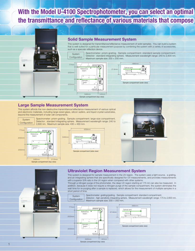
This system is designed for sample measurement in the UV region. The system uses a light source, a grating,
and an integrating sphere that are specifically designed for UV measurements, and provides measurements
with a superior S/N ratio in the UV region when compared with other systems.
Through a nitrogen purge of the photometer, the deep UV region starting at 175 nm can also be measured. In
addition, because it does not require a nitrogen purge of the sample compartment, the system eliminates the
wait time for re-purging after a sample is replaced, which allows for the measurement of multiple samples in a
short period of time.
1
Solid Sample Measurement System
Ultraviolet Region Measurement System
Large Sample Measurement SystemThis system affords the non-destructive transmittance/reflectance measurement of various optical
and electronic materials, including large-sized glass, silicon wafers, and liquid crystal substrates,
beyond the measurement of solar cell components.
This system is designed for transmittance/reflectance measurement of solid samples. You can build a system
that is well-suited for a particular measurement purpose by combining the system with a variety of accessories,
such as a specular reflection device.
Spectrometer: prism-grating. Sample compartment: standard sample compartment.
Detector: standard integrating sphere. Measurement wavelength range: 240 to 2,600 nm.
Maximum sample size: 200 × 200 mm.
With the Model U-4100 Spectrophotometer, you can select an optimal the transmittance and reflectance of various materials that compose
System
Configuration
Spectrometer: prism-grating. Sample compartment: large-size compartment.
Detector: standard integrating sphere. Measurement wavelength range: 240 to
2,600 nm. Maximum sample size: 430 × 430 mm.
System
Configuration
Spectrometer: grating/grating. Sample compartment: standard compartment.
Detector: high-sensitivity integrating sphere. Measurement wavelength range: 175 to 2,600 nm.
Maximum sample size: 200 × 200 mm.
System
Configuration
Referencebeam
Optical axis
Sample compartment (top view)
Sample compartment (top view)
Sample compartment (side view)
Sample compartment (side view)
Samplebeam
Referencebeam Optical axis
Samplebeam
Referencebeam
Optical axis
Samplebeam
Sample compartment (top view)
Sample compartment (side view)
*1: Not applicable to samples having a light-scattering property.
2
System applied to
Large UVSolidAccessory Example
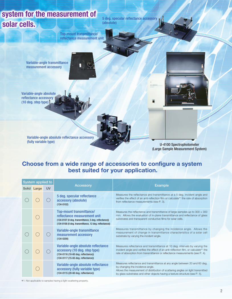
system for the measurement of solar cells.
5 deg. specular reflectance accessory (absolute)
Top-mount transmittance/reflectance measurement unit
Variable-angle transmittance measurement accessory
Variable-angle absolute reflectance accessory (10 deg. step type)
Variable-angle absolute reflectance accessory (fully variable type)
U-4100 Spectrophotometer(Large Sample Measurement System)
Choose from a wide range of accessories to configure a system best suited for your application.
5 deg. specular reflectance accessory (absolute)(134-0102)
Top-mount transmittance/reflectance measurement unit(134-0107 (0 deg. transmittance, 5 deg. reflectance))
(134-0108 (0 deg. transmittance, 12 deg. reflectance))
Variable-angle transmittance measurement accessory(134-0200)
Variable-angle absolute reflectance accessory (10 deg. step type) (134-0116 (10-60 deg. reflectance))
(134-0117 (15-65 deg. reflectance))
Variable-angle absolute reflectance accessory (fully variable type)(134-0115 (20-60 deg. reflectance))
Measures the reflectance and transmittance at a 5 deg. incident angle and
verifies the effect of an anti-reflection film or calculate*1 the rate of absorption
from reflectance measurements (see P. 3).
Measures the reflectance and transmittance of large samples up to 300 × 300
mm. Allows the evaluation of in-plane transmittance and reflectance of glass
substrates and transparent conductive films for solar cells.
Measures transmittance by changing the incidence angle. Allows the
measurement of change in transmittance characteristics of a solar cell
substrate by varying the incident angle.
Measures reflectance and transmittance at 10 deg. intervals by varying the
incident angle and verifies the effect of an anti-reflection film, or calculate*1 the
rate of absorption from transmittance or reflectance measurements (see P. 4).
Measures reflectance and transmittance at any angle between 20 and 60 deg.
by changing the incidence angle.
Allows the measurement of distribution of scattering angles on light transmitted
by glass substrates and other objects having a texture structure (see P. 5).
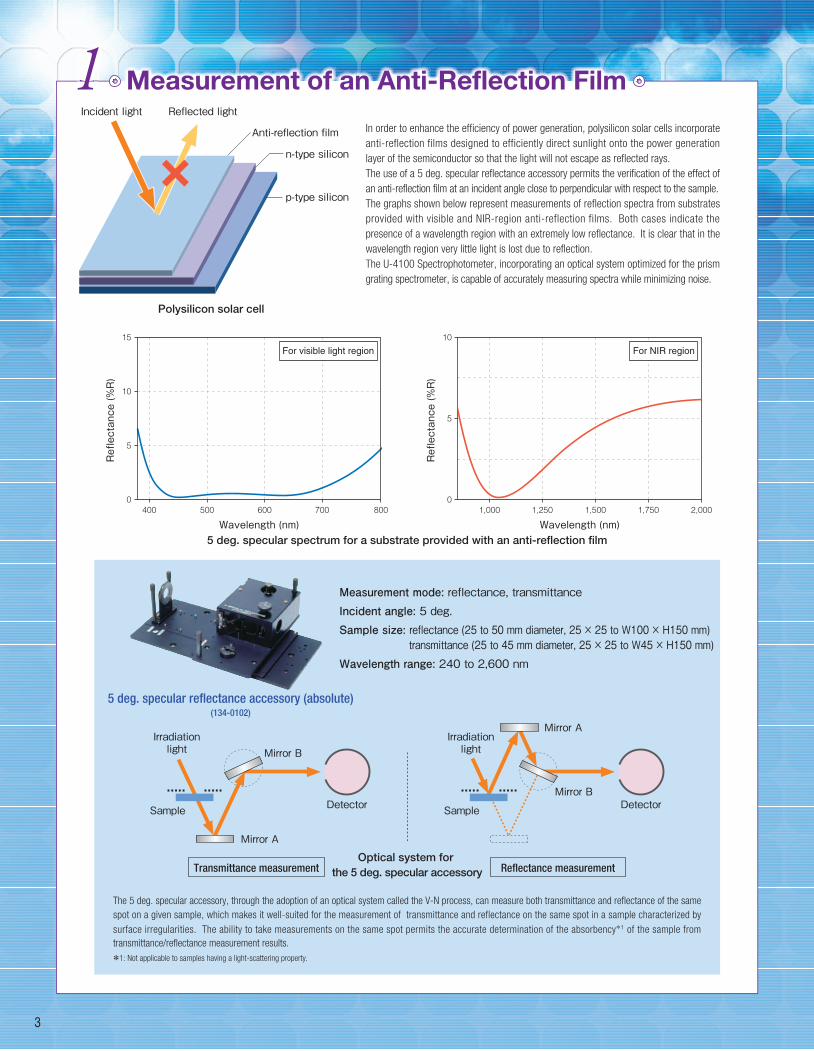
Measurement of an Anti-Reflection Film
In order to enhance the efficiency of power generation, polysilicon solar cells incorporate
anti-reflection films designed to efficiently direct sunlight onto the power generation
layer of the semiconductor so that the light will not escape as reflected rays.
The use of a 5 deg. specular reflectance accessory permits the verification of the effect of
an anti-reflection film at an incident angle close to perpendicular with respect to the sample.
The graphs shown below represent measurements of reflection spectra from substrates
provided with visible and NIR-region anti-reflection films. Both cases indicate the
presence of a wavelength region with an extremely low reflectance. It is clear that in the
wavelength region very little light is lost due to reflection.
The U-4100 Spectrophotometer, incorporating an optical system optimized for the prism
grating spectrometer, is capable of accurately measuring spectra while minimizing noise.
The 5 deg. specular accessory, through the adoption of an optical system called the V-N process, can measure both transmittance and reflectance of the same
spot on a given sample, which makes it well-suited for the measurement of transmittance and reflectance on the same spot in a sample characterized by
surface irregularities. The ability to take measurements on the same spot permits the accurate determination of the absorbency*1 of the sample from
transmittance/reflectance measurement results.
Polysilicon solar cell
Incident light Reflected light
Measurement mode: reflectance, transmittanceIncident angle: 5 deg.Sample size: reflectance (25 to 50 mm diameter, 25 × 25 to W100 × H150 mm) transmittance (25 to 45 mm diameter, 25 × 25 to W45 × H150 mm)Wavelength range: 240 to 2,600 nm
5 deg. specular reflectance accessory (absolute)(134-0102)
5 deg. specular spectrum for a substrate provided with an anti-reflection film
Optical system for the 5 deg. specular accessoryTransmittance measurement Reflectance measurement
3
1Anti-reflection film
p-type silicon
n-type silicon
Irradiationlight
Sample
Mirror A
Mirror B
Detector
Irradiationlight
Sample
Mirror BDetector
Mirror A
For visible light region
Reflectance (%R)
15
10
5
0
Wavelength (nm)400 500 600 700 800
For NIR region
Reflectance (%R)
10
5
0
Wavelength (nm)1,000 1,250 1,500 1,750 2,000
*1: Not applicable to samples having a light-scattering property.
4
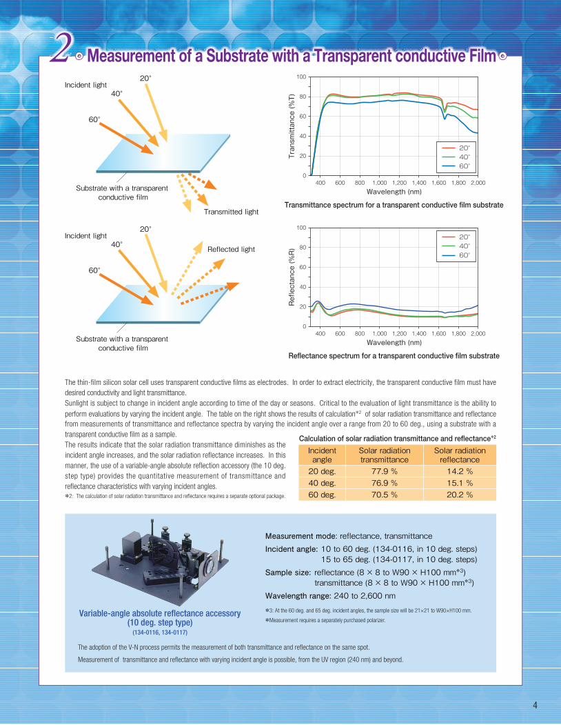
Measurement of a Substrate with a Transparent conductive Film
The adoption of the V-N process permits the measurement of both transmittance and reflectance on the same spot.
Measurement of transmittance and reflectance with varying incident angle is possible, from the UV region (240 nm) and beyond.
20°Incident light
40°
60°
Transmitted light
Measurement mode: reflectance, transmittanceIncident angle: 10 to 60 deg. (134-0116, in 10 deg. steps) 15 to 65 deg. (134-0117, in 10 deg. steps)Sample size: reflectance (8 × 8 to W90 × H100 mm*3) transmittance (8 × 8 to W90 × H100 mm*3)Wavelength range: 240 to 2,600 nm
*3: At the 60 deg. and 65 deg. incident angles, the sample size will be 21×21 to W90×H100 mm.
*Measurement requires a separately purchased polarizer.Variable-angle absolute reflectance accessory
(10 deg. step type)(134-0116, 134-0117)
Substrate with a transparent conductive film
Substrate with a transparent conductive film
2
20°Incident light
40°
60°
Reflected light
Incidentangle20 deg.40 deg.60 deg.
Solar radiationtransmittance77.9 %76.9 %70.5 %
Solar radiationreflectance14.2 %15.1 %20.2 %
The thin-film silicon solar cell uses transparent conductive films as electrodes. In order to extract electricity, the transparent conductive film must have
desired conductivity and light transmittance.
Sunlight is subject to change in incident angle according to time of the day or seasons. Critical to the evaluation of light transmittance is the ability to
perform evaluations by varying the incident angle. The table on the right shows the results of calculation*2 of solar radiation transmittance and reflectance
from measurements of transmittance and reflectance spectra by varying the incident angle over a range from 20 to 60 deg., using a substrate with a
transparent conductive film as a sample.
The results indicate that the solar radiation transmittance diminishes as the
incident angle increases, and the solar radiation reflectance increases. In this
manner, the use of a variable-angle absolute reflection accessory (the 10 deg.
step type) provides the quantitative measurement of transmittance and
reflectance characteristics with varying incident angles.
*2: The calculation of solar radiation transmittance and reflectance requires a separate optional package.
Reflectance spectrum for a transparent conductive film substrate
Wavelength (nm)
20°40°60°
Wavelength (nm)400 600 800 1,000 1,200 1,400 1,600 1,800 2,000
60
80
100
20
40
0
Transmittance (%T)
20°40°60°
400 600 800 1,000 1,200 1,400 1,600 1,800 2,000
60
80
100
20
40
0
Reflectance (%R)
Transmittance spectrum for a transparent conductive film substrate
Calculation of solar radiation transmittance and reflectance*2

Measurement of Textured Glass
Measuring Transmittance in All Directions
Measurement mode: Transmittance (permits measurements including diffusion transmittance)Sample size: 30 × 30 to 100 × 100 mmWavelength range: The same as the specifications for Model U-4100 systems
5
3In order to increase power generation efficiency, a fine pyramid structure called the
texture structure is formed on the light-receiving surface of monosilicon and the glass
panel of a solar cell. The formation of this structure causes the light entering the power
generation layer to repeatedly undergo transmission, reflection, and scattering. As a
result, more light can be directed to the power generation layer when compared with a
flat surface, thus enhancing power generation efficiency.
Such a structure must satisfy the requirements of light diffusion and high transmittance.
Critical to the accurate measurement of the transmittance is the tight adhesion of the
sample to the integrating sphere. The use of a transmission holder (tight adhesion)
permits the strong adhesion of the sample to the integrating sphere and the
measurement of transmittance including diffusion transmittance.
The above graph shows the measurement of the transmittance of a glass panel
having a light-diffusion structure in two situations: with a sample tightly attached
to the integrating sphere and a sample off the integrating sphere. The results
indicate that the tight adhesion of the sample produces high transmittance, and
permits measurements including diffusion transmittance.
Measuring transmittance including diffusion transmission
Example of a solar cell with a texture structure
By tightly attaching the sample to the integrating sphere, it is possible to
measure transmittance including diffusion transmittance.
Transmission holder (tight attachment)(1J0-0202)
Detector (integrating sphere)
Transmission holder(tight attachment)
Sample
Incident light
Incident light
Transmitted light
Detector(integrating sphere)
Sample
移動可能
Measuring the transmittance of a glass panel
Sample tightly attached to the integrating sphere
Sample off the integrating sphere
100
80
60
20
40
0
Transmittance (%)
Wavelength (nm)500 1,000 1,500 2,000 2,500
Light irradiation inside a solar cell
Glass
Transparent conductive film
α.Si.H layer
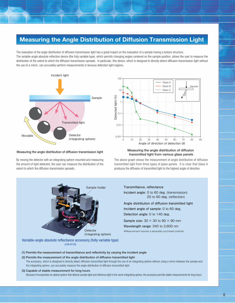
Measuring the Angle Distribution of Diffusion Transmission Light
6
(1) Permits the measurement of transmittance and reflectivity by varying the incident angle
(2) Permits the measurement of the angle distribution of diffusion transmitted lightThe accessory, which is designed to directly detect diffusion transmitted light through the use of an integrating sphere without using a mirror between the sample and
the integrating sphere, can accurately measure the angle distribution of diffusion transmitted light.
(3) Capable of stable measurement for long hoursBecause it incorporates an optical system that detects sample light and reference light in the same integrating sphere, the accessory permits stable measurements for long hours.
Transmittance, reflectanceIncident angle: 0 to 60 deg. (transmission) 20 to 60 deg. (reflection)
Angle distribution of diffusion transmitted lightIncident angle of sample: 0 to 60 deg.Detection angle: 0 to 140 deg.
Sample size: 30 × 30 to 90 × 90 mmWavelength range: 340 to 2,600 nm*Measurement requires a separately purchased polarizer.
Variable-angle absolute reflectance accessory (fully variable type)(134-0115)
The evaluation of the angle distribution of diffusion transmission light has a great impact on the evaluation of a sample having a texture structure.
The variable-angle absolute reflection device (the fully variable type), which permits changing angles centered on the sample position, allows the user to measure the
distribution of the extent to which the diffusion transmission spreads. In particular, this device, which is designed to directly detect diffusion transmission light without
the use of a mirror, can accurately perform measurements in tenuous detection light regions.
The above graph shows the measurement of angle distribution of diffusion
transmitted light from three types of glass panels. It is clear that Glass A
produces the diffusion of transmitted light to the highest angle of direction.
Measuring the angle distribution of diffusion transmission light
By moving the detector with an integrating sphere mounted and measuring
the amount of light detected, the user can measure the distribution of the
extent to which the diffusion transmission spreads.
Incident light
Transmitted light
Detector(integrating sphere)
Movable
Sample
Sample holder
Incidentlight
Detector (integrating sphere)
移動可能移動可能Movable
Measuring the angle distribution of diffusion transmitted light from various glass panels
Glass A
Glass B
Glass C
Sample
θ
Detected light (%)
100
10
1
0.1
0.01
0.001
Angle of direction of detection (θ)10 20 30 40 50 60 70 80 900
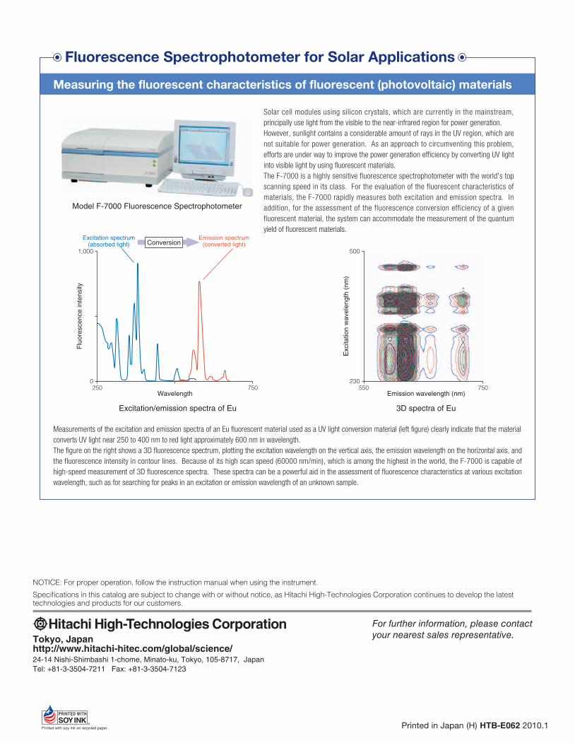
Fluorescence Spectrophotometer for Solar Applications
Solar cell modules using silicon crystals, which are currently in the mainstream,
principally use light from the visible to the near-infrared region for power generation.
However, sunlight contains a considerable amount of rays in the UV region, which are
not suitable for power generation. As an approach to circumventing this problem,
efforts are under way to improve the power generation efficiency by converting UV light
into visible light by using fluorescent materials.
The F-7000 is a highly sensitive fluorescence spectrophotometer with the world's top
scanning speed in its class. For the evaluation of the fluorescent characteristics of
materials, the F-7000 rapidly measures both excitation and emission spectra. In
addition, for the assessment of the fluorescence conversion efficiency of a given
fluorescent material, the system can accommodate the measurement of the quantum
yield of fluorescent materials.
Measuring the fluorescent characteristics of fluorescent (photovoltaic) materials
Model F-7000 Fluorescence Spectrophotometer
Excitation/emission spectra of Eu
ConversionExcitation spectrum
(absorbed light)Emission spectrum
(converted light)1,000
0250 750
Flu
ore
sce
nce
in
ten
sity
Wavelength
3D spectra of Eu
500
230550 750
Excita
tio
n w
ave
len
gth
(n
m)
Emission wavelength (nm)
Measurements of the excitation and emission spectra of an Eu fluorescent material used as a UV light conversion material (left figure) clearly indicate that the material
converts UV light near 250 to 400 nm to red light approximately 600 nm in wavelength.
The figure on the right shows a 3D fluorescence spectrum, plotting the excitation wavelength on the vertical axis, the emission wavelength on the horizontal axis, and
the fluorescence intensity in contour lines. Because of its high scan speed (60000 nm/min), which is among the highest in the world, the F-7000 is capable of
high-speed measurement of 3D fluorescence spectra. These spectra can be a powerful aid in the assessment of fluorescence characteristics at various excitation
wavelength, such as for searching for peaks in an excitation or emission wavelength of an unknown sample.
NOTICE: For proper operation, follow the instruction manual when using the instrument.
Specifications in this catalog are subject to change with or without notice, as Hitachi High-Technologies Corporation continues to develop the latest technologies and products for our customers.
Tokyo, Japanhttp://www.hitachi-hitec.com/global/science/24-14 Nishi-Shimbashi 1-chome, Minato-ku, Tokyo, 105-8717, Japan
Tel: +81-3-3504-7211 Fax: +81-3-3504-7123
For further information, please contact your nearest sales representative.
Printed in Japan (H) HTB-E062 2010.1