a quantum fredkin gate - arxiv · the quantum fredkin gate, shown in fig. 1a, is a three-qubit gate...
TRANSCRIPT
A quantum Fredkin gate
Raj B. Patel,1,∗ Joseph Ho,1 Franck Ferreyrol,1,2 Timothy C. Ralph,3
& Geoff J. Pryde,1,∗
1CQC2T and Centre for Quantum Dynamics, Griffith University,Brisbane 4111, Australia
2 Laboratoire Photonique, Numerique et Nanosciences, Institut d’Optique,CNRS and Universite de Bordeaux, Talence, France
3 CQC2T and School of Mathematics and Physics, University of Queensland,Brisbane 4072, Australia
∗To whom correspondence should be addressed; E-mail: [email protected] [email protected]
Key to realising quantum computers is minimising the resources required to build logic gates into useful processingcircuits. While the salient features of a quantum computer have been shown in proof-of-principle experiments,difficulties in scaling quantum systems have made more complex operations intractable. This is exemplified in theclassical Fredkin (controlled-SWAP) gate for which, despite theoretical proposals, no quantum analogue has beenrealised. By adding control to the SWAP unitary, we use photonic qubit logic to demonstrate the first quantumFredkin gate, which promises many applications in quantum information and measurement. We implement ex-ample algorithms and generate the highest-fidelity three-photon GHZ states to-date. The technique we use allowsone to add a control operation to a black-box unitary, something impossible in the standard circuit model. Ourexperiment represents the first use of this technique to control a two-qubit operation and paves the way for largercontrolled circuits to be realised efficiently.
Introduction
One of the greatest challenges in modern science is the reali-sation of quantum computers (1–3) which, as they increase inscale, will allow enhanced performance of tasks in secure net-working, simulations, distributed computing and other key taskswhere exponential speedups are available. Processing circuits torealise these applications are built up from logic gates that har-ness quantum effects such as superposition and entanglement.At present, even small-scale and medium-scale quantum com-puter circuits are hard to realise because of the requirement tocontrol enough quantum systems sufficiently well in order tochain together many gates into circuits. One example of this isthe quantum Fredkin gate, which requires at least five two-qubitgates (4) to be implemented in the standard circuit model. Thus,despite featuring prominently in schemes for quantum compu-tation (5–7), error-correction (8, 9), cryptography (10–12), andmeasurement (13, 14), no such gate has been realised to date.
The quantum Fredkin gate, shown in Fig. 1A, is a three-qubitgate whereby, conditioned on the state of the control qubit, thequantum states of the two target qubits are swapped. The orig-inal, classical version of the gate first proposed by Fredkin (15)also serves as one of the first examples of a reversible logic op-eration where the number of bits are conserved and no energy isdissipated as a result of erasure. In the framework of universalquantum computation, gates are also reversible, so it may seem
natural to ask whether it is possible to construct a quantum ver-sion of the Fredkin gate. The first design of the quantum Fred-kin gate was proposed by Milburn (16) and was to use singlephotons as qubits and cross-Kerr nonlinearities to produce thenecessary coherent interactions. Further schemes utilising linearoptics developed these ideas further (4, 17–20) by using ancillaphotons, interference, and multiple two-qubit (21,22) and single-qubit gates. However concatenating multiple probabilistic gatesin this fashion typically leads to a multiplicative reduction in theoverall probability of success of < 1/100. Hence it would bedesirable to be able to construct a quantum Fredkin gate directlywithout decomposition and avoid the associated resource over-head.
We begin by describing the concept of our experiment. Weperform the controlled-SWAP operation by adding control tothe SWAP unitary USWAP applying the technique in Zhou etal. (23), to greatly reduce the complexity of quantum circuits.The notion of adding control to a black-box unitary is forbid-den or difficult in many architectures (24,25) – optics lends itselfwell to this approach because the optical implementation of theunitary leaves the vacuum state unchanged. Here we utilise thismethod to simplify a controlled multi-qubit operation. A keyidea in our demonstration is to use entanglement in a non-qubitdegree of freedom (we use the photon’s path mode) to drive theoperation of the gate. This path entanglement can be producedin different ways. In our demonstration (Fig. 1B), it is generated
1
arX
iv:1
603.
0808
6v1
[qu
ant-
ph]
26
Mar
201
6
1R PBS
NPBS
NPBS
NPBSTrigger
1B
2R
1G2B
1Y
2G
2Y
B
000
001
010
011
100
101
110
111
000001
010011
100101
110111
1.0
0.8
0.6
0.4
0.2
0.0
Input State
Output
State
Prob
abili
ty
DA
USWAP
T1
C
T2
T1’
C’
T2’
C
KEY: Quarter and half-wave plate
Half-wave plate
Phase fixer
Prism
Fiber coupler/launcherand single mode fiber
Single photon detector
Mirror
Lens
Fiber polarisationcontroller
Polarising beamsplitter/non-polarising beamsplitter
Polarising beamsplitter
Calcite beam displacer
1R
1B1B
2R 1G2B1Y
2G
2Y
C
LBO
BBO
BBO
T1
T2
Trigger
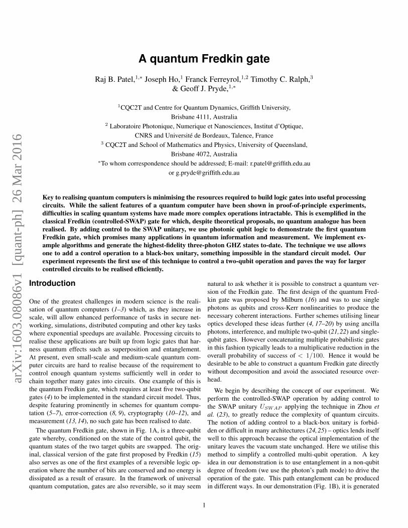
Fig. 1. Experimental arrangement and truth table measurements. A, The quantum Fredkin gate circuit. The states of the target qubits are eitherswapped or not swapped depending on the state of the control qubit. B, Concept of our experiment. Two SPDC photon sources allow production ofpath entanglement such that modes R and Y are entangled with modes B and G. The SWAP operation is carried out on the path modes, dependingon the control photon’s state, such that arrival of the control photon indicates a system state of α|H〉C |ψ〉T1|ϕ〉T2 + β|V 〉C |ϕ〉T1|ψ〉T2. C,The experimental arrangement. Entangled photons are produced via SPDC (see Materials and Methods). Entering the gate via single-mode fiber,the two target photons are sent through a PBS. The path-entangled state in Eq. 1 is produced after each target photon enters a displaced Sagnacinterferometer and the which-path information is erased on an NPBS. QWPs and HWPs encode the polarisation state in Eq. 2. The control consistsof a polarisation beam displacer interferometer. The desired control state is encoded onto modes 1R and 1B and coherently recombined. A tiltedHWP is used to set the phase of the output state. Successful operation is heralded by four-fold coincidence events between the control, target, andtrigger detectors. D, Ideal (transparent bars) and measured (solid bars) truth table data for our gate. A total of 620 four-fold events were measuredfor each of the eight measurements, giving 〈O〉 = 96± 4%.
2
from spontaneous parametric down-conversion (SPDC). Giventhe physical arrangement of the circuit and that we only acceptdetection events where a single photon is counted at each of thefour outputs simultaneously, the optical quantum state producedby SPDC is converted to the required four-photon path-mode en-tangled state (see Materials and Methods) and has the form
(|11〉B |11〉G|00〉R|00〉Y + |00〉B |00〉G|11〉R|11〉Y ) /√2 (1)
where B, R, Y , and G refer to path-modes and, for example,|11〉B indicates a photon occupying mode 1B and another occu-pying 2B. The path-modes are distributed throughout the circuitsuch that USWAP is applied only to the B and G modes. Thequbit state is encoded on the polarisation of the photon. Becausethe photons are in a spatial superposition, polarisation prepara-tion optics must be applied to both path-modes of each photon.Hence, an arbitrary, separable, three-qubit state |ξ〉|ψ〉|ϕ〉 can beprepared as an input to the gate. In particular, the control qubit isencoded on modes 1R and 1B, target 1 is encoded on modes 2Rand 2B, and target 2 is encoded on modes 1G and 1Y , yielding(|ξ〉C1B |ψ〉T1
2B |ϕ〉T21G|H〉Tr2G + |ξ〉C1R|ψ〉T1
2R|ϕ〉T21Y |V 〉Tr2Y
)/√2 (2)
The two control modes 1R and 1B are mixed on a polarisingbeam splitter (PBS), wheras a 50:50 non-polarising beam split-ter (NPBS) is used to erase the path information in the targetand trigger arms. The SWAP is implemented via rearrangementof the path-modes such that the target modes 2B and 1G areswapped wheras 2R and 1Y are not. Successful operation ofthe gate occurs when photons are detected at the control, tar-get 1, and target 2 detectors (simultaneously with a photon de-tection at either trigger detector). The polarisation state of thethree-qubit system, given the required modes are occupied, isα|H〉C |ψ〉T1|ϕ〉T2 +β|V 〉C |ϕ〉T1|ψ〉T2 as expected from appli-cation of the Fredkin gate on the state |ξ〉C |ψ〉T1|ϕ〉T2 where|ξ〉 = α|H〉 + β|V 〉. Taking into consideration the probabilityof recording a four-fold coincidence, successful execution of thegate occurs one-sixteenth of the time, on average. This can be in-creased to one-fourth of the time by collecting the target photonsfrom both NPBS outputs.
Results
The experimental arrangement of the quantum Fredkin gate isshown in Fig. 1C and consists of three interferometers de-signed to be inherently phase-stable. Pairs of polarisation en-tangled photons, produced by two SPDC crystals (see Materialsand Methods), impinge on a PBS. Two orthogonally polarisedphotons, one from each source, are sent to separate displacedSagnac interferometers. Initially, they are incident on a beamsplitter where one half of the interface acts as a PBS and theother half acts as an NPBS. Entering at the PBS side, photonsmay travel along counterpropagating path modes where the po-larisation state |ψ〉 is encoded onto one mode and the state |ϕ〉is encoded on the other. The two paths are then recombined onthe NPBS side of the beam splitter where the path informationis erased (see Methods and Materials), giving the path-mode en-tangled state in equation 1 whilst the polarisation encoding pro-cedure leads to the state in Eq. 2. The control of the gate is
realised in a polarisation interferometer consisting of two calcitebeam displacers. The desired polarisation state of the control isencoded onto modes 1R and 1B, which are coherently recom-bined in the second beam displacer. Given successful operation(arrival of a photon at the control detector), the preparation of thecontrol photon in |H〉 = |1〉 projects the target photons onto pathmodes 1G and 2B which undergo SWAP; conversely, preparing|V 〉 = |0〉 projects the target photons onto path modes 2R and1Y , which undergo the identity operation. In practice, the trig-ger arm consists of a half-wave plate (HWP) whose optic axis(OA) is set to 22.5◦, producing diagonal |D〉 = 1√
2(|H〉 + |V 〉)
or anti-diagonal |A〉 = 1√2(|H〉 − |V 〉) polarised photons, and
a PBS. Successful operation is heralded by measuring four-foldcoincidences across the trigger, control and two target detectors.
The logical operation of the gate was measured by performingeight measurements, one for each of the possible logical inputs.For each input we measure a total of 620 four-fold events dis-tributed across the eight possible output states. Under ideal op-eration, for a given input, there is a single output. The solid barsin Fig. 1D depict the experimentally measured truth table data,Mexp , whereas the transparent bars represent the ideal truth ta-ble Mideal. To quantify the mean overlap between Mexp andMideal, we calculate 〈O〉 = Tr
(MexpM
Tideal/MidealM
Tideal
)=
96 ± 4% which confirms excellent performance in the logicalbasis. The slight reduction in fidelity is most likely due to theimperfect extinction of our polarisation optics.
We demonstrate the full quantum nature of our gate by prepar-ing the control in a superposition |ξ〉 = 1√
2(|0〉 ± |1〉) which
places the gate in a superposition of the SWAP and identityoperations. Using our gate, we produce four of the eightmaximally entangled three-photon Greenberger-Horne-Zeilinger(GHZ) states, namely
1√2(|0〉 ± |1〉)C |1〉T1|0〉T2 → |GHZ±1 〉
=1√2
(|0〉C |1〉T1|0〉T2 ± ei(φ+θ(ϑ))|1〉C |0〉T1|1〉T2
)(3)
and,
1√2(|0〉 ± |1〉)C |0〉T1|1〉T2 → |GHZ±2 〉
=1√2
(|0〉C |0〉T1|1〉T2 ± ei(φ+θ(ϑ))|1〉C |1〉T1|0〉T2
)(4)
Here φ is a phase shift intrinsic to the gate, and θ(ϑ) is a cor-rective phase shift that can be applied by tilting a HWP at OAby an angle ϑ, such that φ + θ(ϑ) = 2nπ (see Materials andMethods). In doing so, we are able to test the coherent interac-tion of all three qubits in the gate, which is a key requirementfor constructing universal quantum computers. For each of thefour states in Eqs. 3 and 4, we perform three-qubit quantum statetomography (QST) to fully characterise the state. The controland target qubits are measured independently in the D/A basis,which we denote as σx; in the R/L basis (σy), where |R〉 =
3
0.5
0.25
0.00
000001010011100101110111
-0.25
-0.5000
001010
011100
101110
111
0.5
0.25
0.00
000001010011100101110111
-0.25
-0.5000
001010
011100
101110
111
A
0.5
0.25
0.00
000001010011100101110111
-0.25
-0.5000
001010
011100
101110
111
0.5
0.25
0.00
000001010011100101110111
-0.25
-0.5000
001010
011100
101110
111
D
0.5
0.25
0.00
000001010011100101110111
-0.25
-0.5000
001010
011100
101110
111
0.5
0.25
0.00
000001010011100101110111
-0.25
-0.5000
001010
011100
101110
111
C
0.5
0.25
0.00
000001010011100101110111
-0.25
-0.5000
001010
011100
101110
111
0.5
0.25
0.00
000001010011100101110111
-0.25
-0.5000
001010
011100
101110
111
B
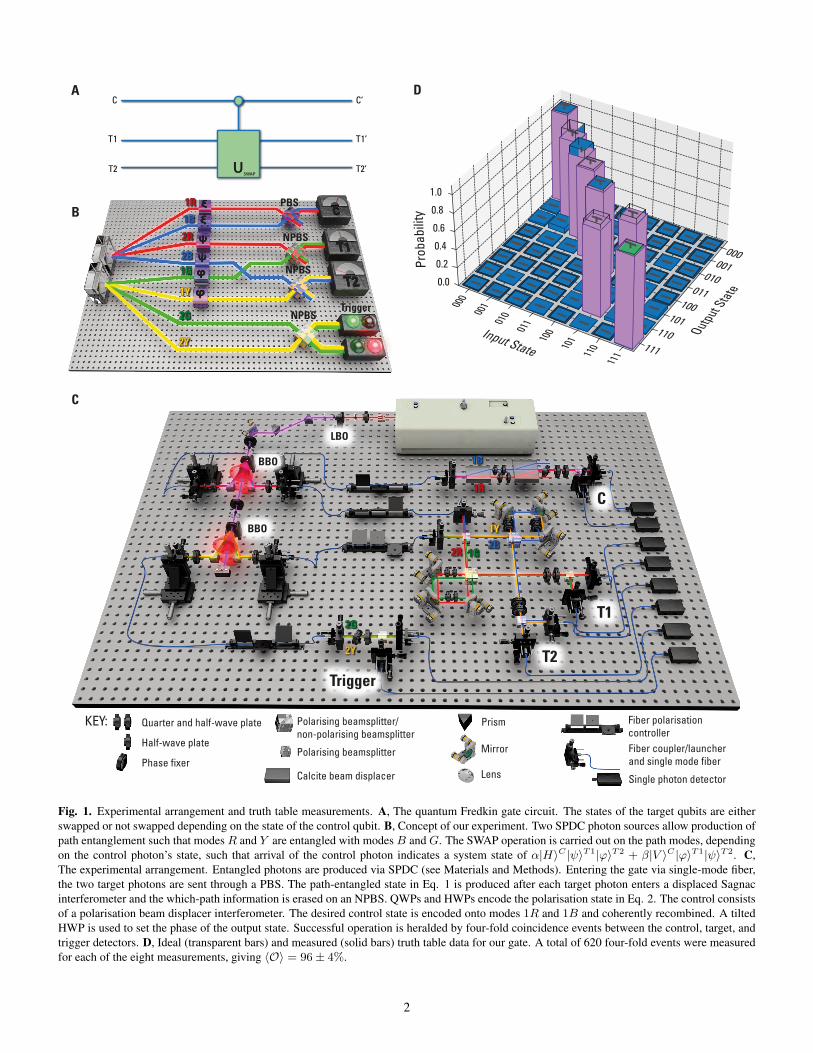
Fig. 2. Real (left) and imaginary (right) parts of the reconstructed density matrices for our four GHZ states. Fidelity and purity were calculatedfor each state. A, |GHZ+
1 〉: F = 0.88. ± 0.01 and P = 0.79 ± 0.02. B, |GHZ−1 〉: F = 0.90 ± 0.01 and P = 0.83 ± 0.02. C, |GHZ+2 〉:
F = 0.93± 0.01 and P = 0.87± 0.02. D, |GHZ−2 〉: F = 0.92± 0.01 and P = 0.85± 0.02.
4
-1.0-0.8-0.6-0.4-0.20.00.20.40.60.81.0
Corr
elat
ion
E(a,b,c)
E(a,b’,c’)
E(a’,b,c’)
E(a’,b’,c)
A
-1.0-0.8-0.6-0.4-0.20.00.20.40.60.81.0
Corr
elat
ion
E(a,b,c)
E(a,b,c’)
E(a,b’,c)
E(a,b’,c’)
E(a’,b,c’)
E(a’,b’,c’)
B
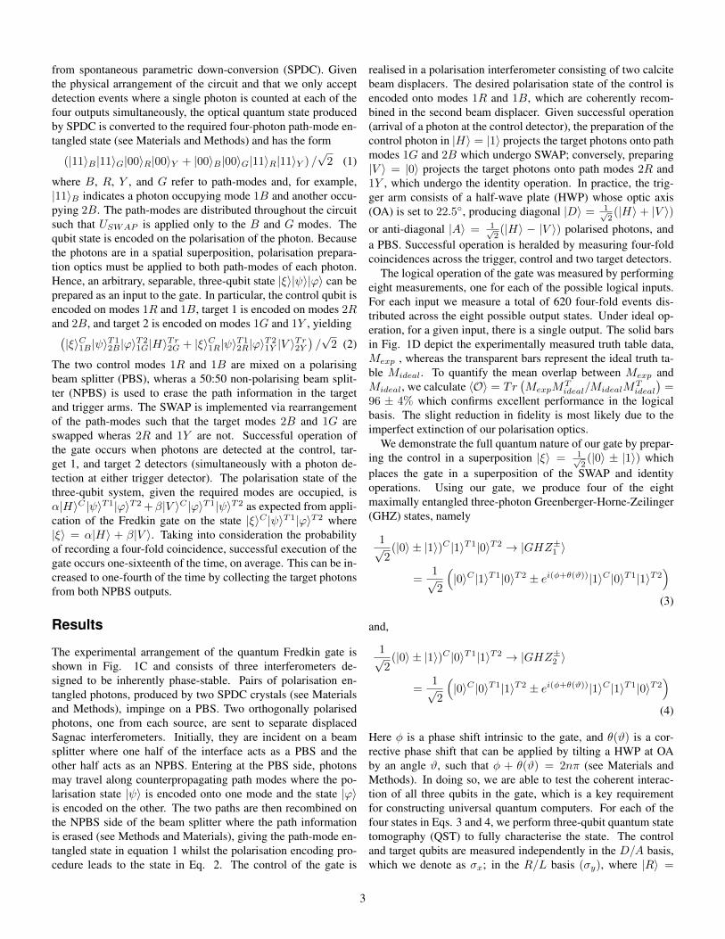
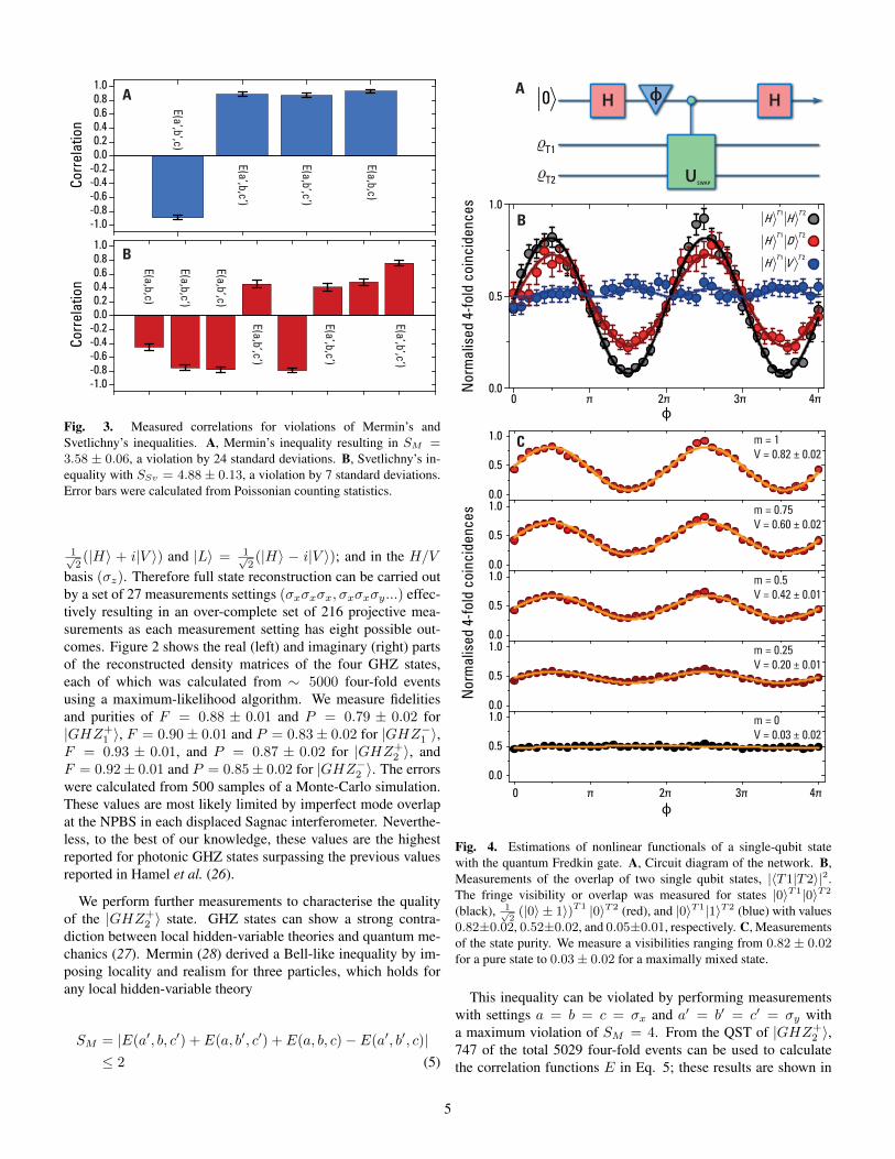
Fig. 3. Measured correlations for violations of Mermin’s andSvetlichny’s inequalities. A, Mermin’s inequality resulting in SM =3.58 ± 0.06, a violation by 24 standard deviations. B, Svetlichny’s in-equality with SSv = 4.88 ± 0.13, a violation by 7 standard deviations.Error bars were calculated from Poissonian counting statistics.
1√2(|H〉 + i|V 〉) and |L〉 = 1√
2(|H〉 − i|V 〉); and in the H/V
basis (σz). Therefore full state reconstruction can be carried outby a set of 27 measurements settings (σxσxσx, σxσxσy...) effec-tively resulting in an over-complete set of 216 projective mea-surements as each measurement setting has eight possible out-comes. Figure 2 shows the real (left) and imaginary (right) partsof the reconstructed density matrices of the four GHZ states,each of which was calculated from ∼ 5000 four-fold eventsusing a maximum-likelihood algorithm. We measure fidelitiesand purities of F = 0.88 ± 0.01 and P = 0.79 ± 0.02 for|GHZ+
1 〉, F = 0.90± 0.01 and P = 0.83± 0.02 for |GHZ−1 〉,F = 0.93 ± 0.01, and P = 0.87 ± 0.02 for |GHZ+
2 〉, andF = 0.92± 0.01 and P = 0.85± 0.02 for |GHZ−2 〉. The errorswere calculated from 500 samples of a Monte-Carlo simulation.These values are most likely limited by imperfect mode overlapat the NPBS in each displaced Sagnac interferometer. Neverthe-less, to the best of our knowledge, these values are the highestreported for photonic GHZ states surpassing the previous valuesreported in Hamel et al. (26).
We perform further measurements to characterise the qualityof the |GHZ+
2 〉 state. GHZ states can show a strong contra-diction between local hidden-variable theories and quantum me-chanics (27). Mermin (28) derived a Bell-like inequality by im-posing locality and realism for three particles, which holds forany local hidden-variable theory
SM = |E(a′, b, c′) + E(a, b′, c′) + E(a, b, c)− E(a′, b′, c)|≤ 2 (5)
0 π 2π 3π 4π0.0
0.5
1.0
Nor
mal
ised
4-f
old
coin
cide
nces
ф
ф0 π 2π 3π 4π
Nor
mal
ised
4-f
old
coin
cide
nces
0.0
0.5
1.0
0.0
0.5
1.0
0.0
0.5
1.0
0.0
0.5
1.0
0.0
0.5
1.0
m = 1V = 0.82 ± 0.02
m = 0.75V = 0.60 ± 0.02
m = 0.5V = 0.42 ± 0.01
m = 0.25V = 0.20 ± 0.01
m = 0V = 0.03 ± 0.02
B
C
AH H
USWAP
0
T1
T2
ф
1 2
1 2
1 2
T T
T T
T T
H H
H D
H V
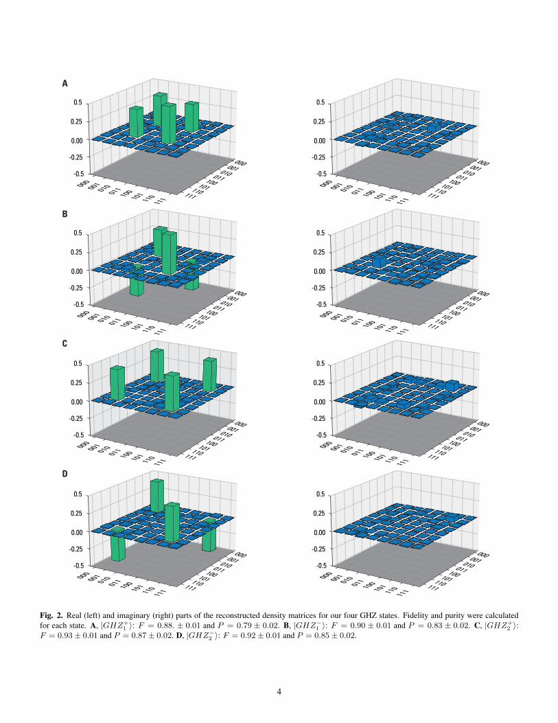
Fig. 4. Estimations of nonlinear functionals of a single-qubit statewith the quantum Fredkin gate. A, Circuit diagram of the network. B,Measurements of the overlap of two single qubit states, |〈T1|T2〉|2.The fringe visibility or overlap was measured for states |0〉T1|0〉T2
(black), 1√2(|0〉 ± 1〉)T1 |0〉T2 (red), and |0〉T1|1〉T2 (blue) with values
0.82±0.02, 0.52±0.02, and 0.05±0.01, respectively. C, Measurementsof the state purity. We measure a visibilities ranging from 0.82 ± 0.02for a pure state to 0.03± 0.02 for a maximally mixed state.
This inequality can be violated by performing measurementswith settings a = b = c = σx and a′ = b′ = c′ = σy witha maximum violation of SM = 4. From the QST of |GHZ+
2 〉,747 of the total 5029 four-fold events can be used to calculatethe correlation functions E in Eq. 5; these results are shown in
5
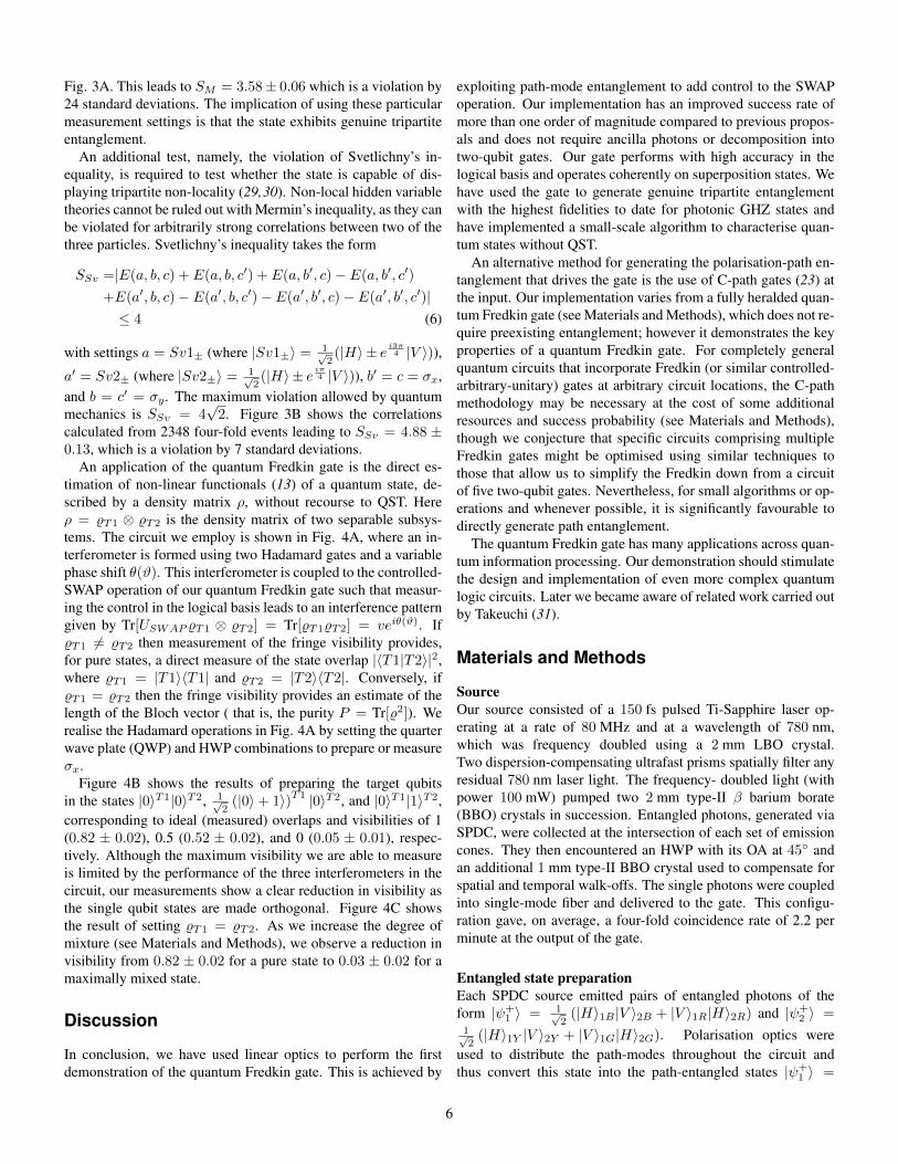
Fig. 3A. This leads to SM = 3.58± 0.06 which is a violation by24 standard deviations. The implication of using these particularmeasurement settings is that the state exhibits genuine tripartiteentanglement.
An additional test, namely, the violation of Svetlichny’s in-equality, is required to test whether the state is capable of dis-playing tripartite non-locality (29,30). Non-local hidden variabletheories cannot be ruled out with Mermin’s inequality, as they canbe violated for arbitrarily strong correlations between two of thethree particles. Svetlichny’s inequality takes the form
SSv =|E(a, b, c) + E(a, b, c′) + E(a, b′, c)− E(a, b′, c′)
+E(a′, b, c)− E(a′, b, c′)− E(a′, b′, c)− E(a′, b′, c′)|≤ 4 (6)
with settings a = Sv1± (where |Sv1±〉 = 1√2(|H〉 ± e i3π4 |V 〉)),
a′ = Sv2± (where |Sv2±〉 = 1√2(|H〉 ± e iπ4 |V 〉)), b′ = c = σx,
and b = c′ = σy . The maximum violation allowed by quantummechanics is SSv = 4
√2. Figure 3B shows the correlations
calculated from 2348 four-fold events leading to SSv = 4.88 ±0.13, which is a violation by 7 standard deviations.
An application of the quantum Fredkin gate is the direct es-timation of non-linear functionals (13) of a quantum state, de-scribed by a density matrix ρ, without recourse to QST. Hereρ = %T1 ⊗ %T2 is the density matrix of two separable subsys-tems. The circuit we employ is shown in Fig. 4A, where an in-terferometer is formed using two Hadamard gates and a variablephase shift θ(ϑ). This interferometer is coupled to the controlled-SWAP operation of our quantum Fredkin gate such that measur-ing the control in the logical basis leads to an interference patterngiven by Tr[USWAP %T1 ⊗ %T2] = Tr[%T1%T2] = veiθ(ϑ). If%T1 6= %T2 then measurement of the fringe visibility provides,for pure states, a direct measure of the state overlap |〈T1|T2〉|2,where %T1 = |T1〉〈T1| and %T2 = |T2〉〈T2|. Conversely, if%T1 = %T2 then the fringe visibility provides an estimate of thelength of the Bloch vector ( that is, the purity P = Tr[%2]). Werealise the Hadamard operations in Fig. 4A by setting the quarterwave plate (QWP) and HWP combinations to prepare or measureσx.
Figure 4B shows the results of preparing the target qubitsin the states |0〉T1|0〉T2, 1√
2(|0〉+ 1〉)T1 |0〉T2, and |0〉T1|1〉T2,
corresponding to ideal (measured) overlaps and visibilities of 1(0.82 ± 0.02), 0.5 (0.52 ± 0.02), and 0 (0.05 ± 0.01), respec-tively. Although the maximum visibility we are able to measureis limited by the performance of the three interferometers in thecircuit, our measurements show a clear reduction in visibility asthe single qubit states are made orthogonal. Figure 4C showsthe result of setting %T1 = %T2. As we increase the degree ofmixture (see Materials and Methods), we observe a reduction invisibility from 0.82 ± 0.02 for a pure state to 0.03 ± 0.02 for amaximally mixed state.
Discussion
In conclusion, we have used linear optics to perform the firstdemonstration of the quantum Fredkin gate. This is achieved by
exploiting path-mode entanglement to add control to the SWAPoperation. Our implementation has an improved success rate ofmore than one order of magnitude compared to previous propos-als and does not require ancilla photons or decomposition intotwo-qubit gates. Our gate performs with high accuracy in thelogical basis and operates coherently on superposition states. Wehave used the gate to generate genuine tripartite entanglementwith the highest fidelities to date for photonic GHZ states andhave implemented a small-scale algorithm to characterise quan-tum states without QST.
An alternative method for generating the polarisation-path en-tanglement that drives the gate is the use of C-path gates (23) atthe input. Our implementation varies from a fully heralded quan-tum Fredkin gate (see Materials and Methods), which does not re-quire preexisting entanglement; however it demonstrates the keyproperties of a quantum Fredkin gate. For completely generalquantum circuits that incorporate Fredkin (or similar controlled-arbitrary-unitary) gates at arbitrary circuit locations, the C-pathmethodology may be necessary at the cost of some additionalresources and success probability (see Materials and Methods),though we conjecture that specific circuits comprising multipleFredkin gates might be optimised using similar techniques tothose that allow us to simplify the Fredkin down from a circuitof five two-qubit gates. Nevertheless, for small algorithms or op-erations and whenever possible, it is significantly favourable todirectly generate path entanglement.
The quantum Fredkin gate has many applications across quan-tum information processing. Our demonstration should stimulatethe design and implementation of even more complex quantumlogic circuits. Later we became aware of related work carried outby Takeuchi (31).
Materials and Methods
SourceOur source consisted of a 150 fs pulsed Ti-Sapphire laser op-erating at a rate of 80 MHz and at a wavelength of 780 nm,which was frequency doubled using a 2 mm LBO crystal.Two dispersion-compensating ultrafast prisms spatially filter anyresidual 780 nm laser light. The frequency- doubled light (withpower 100 mW) pumped two 2 mm type-II β barium borate(BBO) crystals in succession. Entangled photons, generated viaSPDC, were collected at the intersection of each set of emissioncones. They then encountered an HWP with its OA at 45◦ andan additional 1 mm type-II BBO crystal used to compensate forspatial and temporal walk-offs. The single photons were coupledinto single-mode fiber and delivered to the gate. This configu-ration gave, on average, a four-fold coincidence rate of 2.2 perminute at the output of the gate.
Entangled state preparationEach SPDC source emitted pairs of entangled photons of theform |ψ+
1 〉 = 1√2(|H〉1B |V 〉2B + |V 〉1R|H〉2R) and |ψ+
2 〉 =1√2(|H〉1Y |V 〉2Y + |V 〉1G|H〉2G). Polarisation optics were
used to distribute the path-modes throughout the circuit andthus convert this state into the path-entangled states |ψ+
1 〉 =
6
1√2(|1〉1B |1〉2B |0〉1R|0〉2R + |0〉1B |0〉2B |1〉1R|1〉2R) and
|ψ+2 〉 = 1√
2(|1〉1Y |1〉2Y |0〉1G|0〉2G + |0〉1Y |0〉2Y |1〉1G|1〉2G).
Path modes from |ψ+1 〉 and |ψ+
2 〉 were combined on a PBS (Fig1C, PBS with outputs 2R, 1G, 1Y , and 2B); along with post-selection of four-fold coincidence events at the outputs of thecontrol, target, and trigger outputs, this led to Eq. (1) in the maintext. Each qubit was encoded using photon polarisation: usingEq. (1), considering that each photon exists in a superpositionof path-modes and omitting the unoccupied modes, an arbitrarypolarisation state can be encoded onto each qubit by performinga local unitary operation on each mode, giving equation (2). Thestate encoding was performed inside the beam displacer (controlqubit) and displaced Sagnac (target qubits) interferometers.
Tuning the phaseThe phase was tuned by tilting an HWP set to its OA. To set thecorrect phase for each of the four GHZ states, we varied the tiltof the HWP and measured fringes in the four-fold coincidenceswith our measurement apparatus in the σxσyσy basis. For the|GHZ+
1,2〉(|GHZ−1,2〉
)we set the tilt to maximise (minimise) the
occurrence of the |DRR〉, |DLL〉, |ARL〉, and |ALR〉 events.
Mixed state preparationThe mixed states of the form % = m|0〉〈0| +(1−m)
2 (|0〉〈0|+ |1〉〈1|) were obtained by measuring outputstatistics for a combination of pure input states. The inputstates of the target were prepared, in varying proportionsgiven by the parameter m, as 0.25(1 + m)2|0〉T1|0〉T2,0.25(1 − m2)|0〉T1|1〉T2, 0.25(1 − m2)|1〉T1|0〉T2, and0.25(1 − m)2|1〉T1|1〉T2. The aggregated data resulted in afringe pattern which reflects the purity of the mixed single-qubitstate.
Erasing the which-path informationGeneration of path-mode entanglement and successful operationof the gate in the quantum regime relied on the erasure of thewhich-path information in the two displaced Sagnac interferom-eters. We tested this by performing a Hong-Ou-Mandel (HOM)two-photon interference measurement after each interferometer.After overlapping path modes 2R and 1G on an NPBS, an HWPwith its OA set to 22.5◦ rotated the polarisation of the photons to|D〉 and |A〉, respectively. Sending these photons into the sameport of a PBS led to bunching at the output if the path-modeswere indistinguishable. Doing the same for modes 2B and 1Ygave two separate HOM dips (see Materials and Methods) withvisibilities of 90± 5% and 91± 6%.
Heralding the quantum Fredkin gateIn order to use a quantum Fredkin gate as part of a much largerquantum circuit (with gates in series), it is preferable for the gateto be heralded. Realising our gate in this manner involves addingC-path gates (23) to each input. For the best probability of suc-cess Psuccess, each C-path gate requires two heralded C-NOTgates (32) which, in turn, require two entangled pair ancillae.Execution of the C-path gate succeeds with Psuccess = (1/4)2
(23,32). C-path gates are not a necessity at the output if success-ful execution is heralded by non-detections at the relevant NPBSports, at an additional probability cost of factor 1/4.
References
1. P. Kok, K. Nemoto, T. C. Ralph, J. P. Dowling, G. J. Milburn,Linear optical quantum computing with photonic qubits.Rev. Mod. Phys. 79, 135-174 (2007).
2. J. L. O’Brien, A. Furusawa, J. Vuckovic, Photonic quantumtechnologies. Nature Photon. 3, 687-695 (2009).
3. T. D. Ladd, et al., Quantum computers. Nature 464, 45-53(2010).
4. J. A. Smolin, D. P. DiVincenzo, Five two-bit quantum gatesare sufficient to implement the quantum Fredkin gate. Phys.Rev. A. 53, 2855-2856 (1996).
5. L. M. K. Vandersypen, et al., Experimental realization ofShor’s quantum factoring algorithm using nuclear magneticresonance. Nature 414, 883-887 (2001).
6. E. Martin-Lopez, et al., Experimental realization of Shor’squantum factoring algorithm using qubit recycling. NaturePhoton. 6, 773-776 (2012).
7. B. Lanyon, et al., Experimental Demonstration of a Com-piled Version of Shor’s Algorithm with Quantum Entangle-ment. Phys. Rev. Lett. 99, 250505 (2007).
8. I. L. Chuang, Y. Yamamoto, Quantum bit regeneration. Phys.Rev. Lett. 76, 4281-4284 (1996).
9. A. Barenco, et al., Stabilisation of Quantum Computationsby Symmetrisation. SIAM J. Comput. 25, 1541 – 1557(1997).
10. H. Buhrman, R. Cleve, J. Watrous, R. de Wolf, QuantumFingerprinting. Phys. Rev. Lett. 87, 167902 (2001).
11. R. Horn, S. Babichev, K.-P. Marzlin, A. Lvovsky,B. Sanders, Single-Qubit Optical Quantum Fingerprinting.Phys. Rev. Lett. 95, 150502 (2005).
12. D. Gottesman, I. Chuang, Quantum digital signatures.arXiv:quant-ph/0105032 (2001).
13. A. Ekert, et al., Direct Estimations of Linear and NonlinearFunctionals of a Quantum State. Phys. Rev. Lett. 88, 217901(2002).
14. J. Fiurasek, M. Dusek, R. Filip, Universal Measurement Ap-paratus Controlled by Quantum Software. Phys. Rev. Lett.89, 190401 (2002).
15. E. Fredkin, T. Toffoli, Conservative Logic. InternationalJournal of Theoretical Physics 21, 219-253 (1982).
16. G. J. Milburn, Quantum Optical Fredkin Gate. Phys. Rev.Lett. 62, 2124-2127 (1989).
7
17. H. Chau, F. Wilczek, Simple Realization of the Fredkin Gateusing a Series of Two-Body Operators. Phys. Rev. Lett. 75,748-750 (1995).
18. J. Fiurasek, Linear-optics quantum Toffoli and Fredkingates. Phys. Rev. A. 73, 062313 (2006).
19. J. Fiurasek, Linear optical Fredkin gate based on partial-SWAP gate. Phys. Rev. A. 78, 032317 (2008).
20. Y. X. Gong, G. C. Guo, T. C. Ralph, Methods for a linear op-tical quantum Fredkin gate. Phys. Rev. A. 78, 012305 (2008).
21. J. L. O’Brien, G. J. Pryde, A. G. White, T. C. Ralph, D. Bran-ning, Demonstration of an all-optical quantum controlled-NOT gate. Nature 426, 264-267 (2003).
22. M. A. Pooley, et al., Controlled-NOT gate operating withsingle photons. Appl. Phys. Lett. 100, 211103 (2012).
23. X. Q. Zhou, et al., Adding control to arbitrary unknownquantum operations. Nature Commun. 2 (2011).
24. M. Araujo, A. Feix, F. Costa, v. Brukner, Quantum circuitscannot control unknown operations. New J. Phys. 16, 093026(2014).
25. J. Thompson, M. Gu, K. Modi, V. Vedral, Quantum comput-ing with black-box subroutines. arXiv:1310.2927v5 (2013).
26. D. R. Hamel, et al., Direct generation of three-photon polar-ization entanglement. Nature Photon. 8, 801–807 (2014).
27. J. W. Pan, D. Bouwmeester, M. Daniell, H. Weinfurter,A. Zeilinger, Experimental test of quantum nonlocalityin three-photon Greenberger-Horne-Zeilinger entanglement.Nature 403, 515-519 (2000).
28. N. D. Mermin, Extreme quantum entanglement in a super-position of macroscopically distinct states. Phys. Rev. Lett.65, 1838-1840 (1990).
29. G. Svetlichny, Distinguishing three-body from two-bodynonseparability by a Bell-type inequality. Phys. Rev. D. 35,3066-3069 (1987).
30. J. Lavoie, R. Kaltenbaek, K. J. Resch, Experimental viola-tion of Svetlichny’s inequality. New J. Phys. 11, 073051(2009).
31. S. Takeuchi. Private communication.
32. T. B. Pittman, B. C. Jacobs, J. D. Franson, Probabilisticquantum logic operations using polarizing beam splitters.Phys. Rev. A 64, 062311 (2001).
Acknowledgements:We thank Sergei Slussarenko, Allen Boston, and Kavan Modi
for useful discussions.Funding: This work was supported by the Australian ResearchCouncil Centre of Excellence for Quantum Computation andCommunication Technology (Project number CE110001027).
Author Contributions T.C.R., F.F., and G.J.P. conceptualisedthe scheme. R.B.P., J.H., and F.F. designed and constructed theexperiment. R.B.P. and J.H. performed the experiment and dataanalysis with input from G.J.P. R.B.P. wrote the manuscript withinput from all authors. G.J.P. oversaw the work.Competing Interests The authors declare that they have no com-peting financial interests.Data and materials availability: All data needed to evaluate theconclusions in the paper are present in the paper itself and in theSupplementary Materials or are available upon request from theauthors.Supplementary Materials:Section S1. Erasing the which-path informationSection S2. Generation of three-photon GHZ statesFig. S1. HOM dip measurements
8
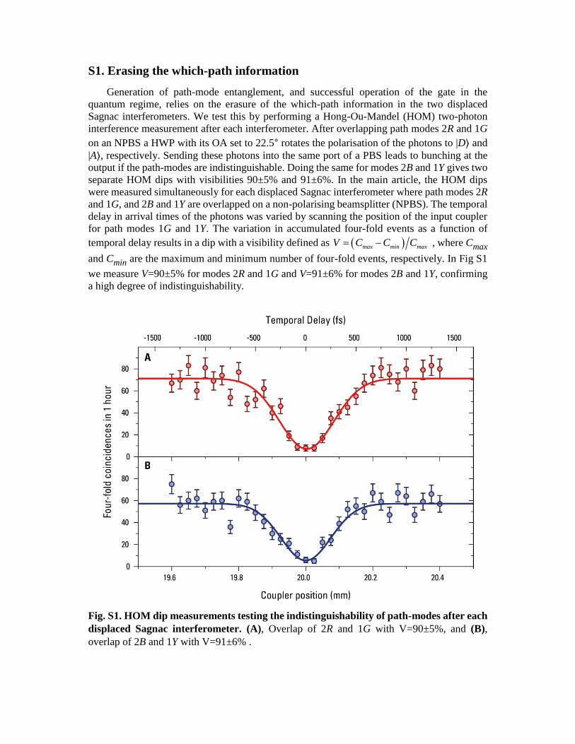
S1. Erasing the which-path information
Generation of path-mode entanglement, and successful operation of the gate in the
quantum regime, relies on the erasure of the which-path information in the two displaced
Sagnac interferometers. We test this by performing a Hong-Ou-Mandel (HOM) two-photon
interference measurement after each interferometer. After overlapping path modes 2R and 1G
on an NPBS a HWP with its OA set to 22.5∘ rotates the polarisation of the photons to |D⟩ and
|A⟩, respectively. Sending these photons into the same port of a PBS leads to bunching at the
output if the path-modes are indistinguishable. Doing the same for modes 2B and 1Y gives two
separate HOM dips with visibilities 90±5% and 91±6%. In the main article, the HOM dips
were measured simultaneously for each displaced Sagnac interferometer where path modes 2R
and 1G, and 2B and 1Y are overlapped on a non-polarising beamsplitter (NPBS). The temporal
delay in arrival times of the photons was varied by scanning the position of the input coupler
for path modes 1G and 1Y. The variation in accumulated four-fold events as a function of
temporal delay results in a dip with a visibility defined as max min maxV C C C , where Cmax
and Cmin are the maximum and minimum number of four-fold events, respectively. In Fig S1
we measure V=90±5% for modes 2R and 1G and V=91±6% for modes 2B and 1Y, confirming
a high degree of indistinguishability.
Fig. S1. HOM dip measurements testing the indistinguishability of path-modes after each
displaced Sagnac interferometer. (A), Overlap of 2R and 1G with V=90±5%, and (B),
overlap of 2B and 1Y with V=91±6% .
S2. Generation of three-photon GHZ states
Here we outline how our quantum Fredkin gate generates four of the eight maximally
entangled three-photon GHZ states. The general four-photon state prior to state preparation is
1 2 1 2
1 2 1 2 1 2 1 22
C T T Tr C T T Tr
B B G G R R Y YH V (S1)
The photons in modes 2G and 2Y pass through a HWP with its OA set to 22.5∘ and then impinge
on a PBS leading to
1 2 1 2
1 2 1 2 1 2 1 2
1 2 1 2
1 2 1 2 1 2 1 2
| | | | | | | |
4 4
| | | | | | | |
4 4
C T T Tr C T T Tr
B B G G B B G G
C T T Tr C T T Tr
R R Y Y R R Y Y
H V
H V (S2)
In order to prepare the gate in a superposition of the SWAP and identity operations the control
qubit is set to 1
2
C C CD H V giving
1 2 1 2
1 2 1 2 1 2 1 2
1 2 1 2
1 2 1 2 1 2 1 2
1 2 1 2
1 2 1 2 1 2 1 2
1 2
1 2 1 2
| | | | | | | |
8 8
| | | | | | | |
8 8
| | | | | | | |
8 8
| | | |
C T T Tr C T T Tr
B B G G B B G G
C T T Tr C T T Tr
B B G G B B G G
C T T Tr C T T Tr
R R Y Y R R Y Y
C T T T
R R Y Y
H H V H
H V V V
H H V H
H V 1 2
1 2 1 2| | | |
8 8
r C T T Tr
R R Y YV V
(S3)
In the control arm of our experiment, the interferometer is arranged such that terms with 1
C
BH
or 1
C
RV in equation (S3) are rejected. Rejecting these terms and swapping modes 2B and 1G
gives
1 21 2
1 1 2 21 2 1 2
1 21 2
1 1 2 21 2 1 2
| | | || | | |
4 4
| | | || | | |
4 4
C T T TrC T T Tr
B G B GR R Y Y
C T T TrC T T Tr
B G B GR R Y Y
V HH H
V VH V (S4)
Consequently from equation (S4) detection of a trigger photon in state H or V will result
in two states with a relative phase difference of π.
1 21 2
1 1 21 2 1| | || | |
| :2 2
C T TC T TTr B G BR R Y
VHH (S5)
1 21 2
1 1 21 2 1| | || | |
| :4 2
C T TC T TTr B G BR R Y
VHV (S6)
As we detect both polarisations of the trigger photon, it is necessary to perform a classical
phase rotation to the coincidence data corresponding to the detection of Tr
V . The two sets of
coincidence data are then combined. After erasing the which-path information, setting
V and H and recalling that 1H and 0V we obtain the three-photon
GHZ state
1 2 1 2
1
10 0 1 10
2
C T T C T T
GHZ . (S7)
Alternatively, setting H and V produces
1 2 1 2
2
00 1 1 01
2
C T T C T T
GHZ . (S8)
Preparing the control in 1
2
C C CA H V and setting V and H gives
1 1 2
1
210 0 1 10
2
C T T C T T
GHZ (S9)
while for H and V
1 2 1 2
2
00 1 1 01
2
C T T C T T
GHZ (S10)