a guide to using acta 3000 - edlo sales manual 2002_04.pdf · edition 2 atlas copco tools ab - 9836...
TRANSCRIPT
Edition 2 Atlas Copco Tools AB - 9836 1818 01 Page 1 (197) 2002-04
A Guide to Using
ACTA 3000 Atlas Copco Tools AB

Contents
3
Contents 1. Safety Instructions...................................................................................................................9 2. System Overview ...................................................................................................................11
2.1 General ........................................................................................................................ 11 2.1.1 ACTA 3000 Basic............................................................................................ 11 2.1.2 ACTA 3000 Quality Control ........................................................................... 11 2.1.3 ACTA 3000 Advanced Analysis...................................................................... 12 2.1.4 ToolsTalk ACTA............................................................................................. 13
3. Installation and startup.........................................................................................................15 3.1 Out of the Box............................................................................................................. 15
3.1.1 Installation....................................................................................................... 15 4. Quick Programming..............................................................................................................17
4.1 General ........................................................................................................................ 17
4.2 Operating Quick-guide ............................................................................................... 17
4.3 Quick programming .................................................................................................... 18
4.4 Your Measurement Results using Quick Programming ............................................ 21 5. Keys and Indicators...............................................................................................................23
5.1 Front Panel.................................................................................................................. 23 5.1.1 Status (LED) Indicators ................................................................................... 24
6. Measurement Dialog boxes...................................................................................................27 6.1 General ........................................................................................................................ 27
6.2 The Different Measurement Dialog boxes................................................................. 27 6.2.1 The “Basic” Measurement Dialog box .......................................................... 28 6.2.2 The “Custom” Measurement Dialog Box...................................................... 28 6.2.3 The “Trace” Measurement Dialog Box ......................................................... 29
6.3 Measurement Dialog box / Menu Block Setup Combinations .................................. 30 6.3.1 Basic ................................................................................................................ 30 6.3.2 Quality Control (QC)....................................................................................... 30 6.3.3 Advanced Analysis (AA) ................................................................................. 31
7. Programming Tree................................................................................................................33 7.1 General ........................................................................................................................ 33
7.2 Using the programming tree....................................................................................... 33 7.2.1 Menu Blocks ................................................................................................... 33 7.2.2 Pop-up Menu ................................................................................................... 34 7.2.3 Data Input Dialog box...................................................................................... 35

Contents
4
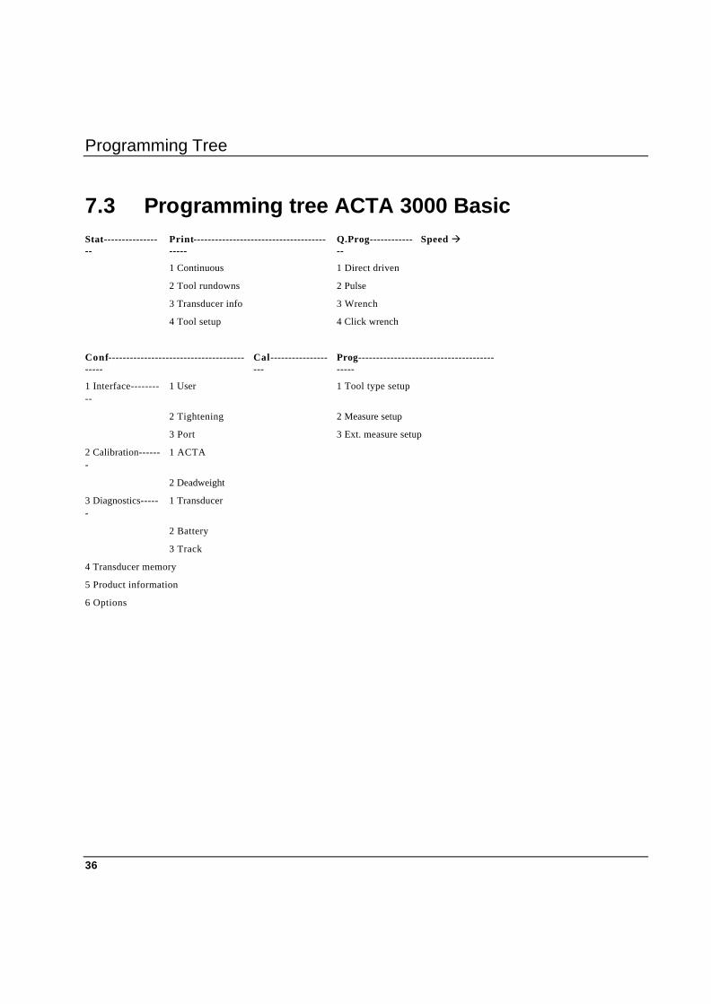
7.3 Programming tree ACTA 3000 Basic......................................................................... 36
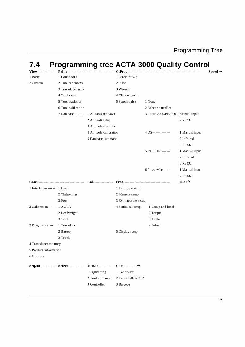
7.4 Programming tree ACTA 3000 Quality Control ........................................................ 37
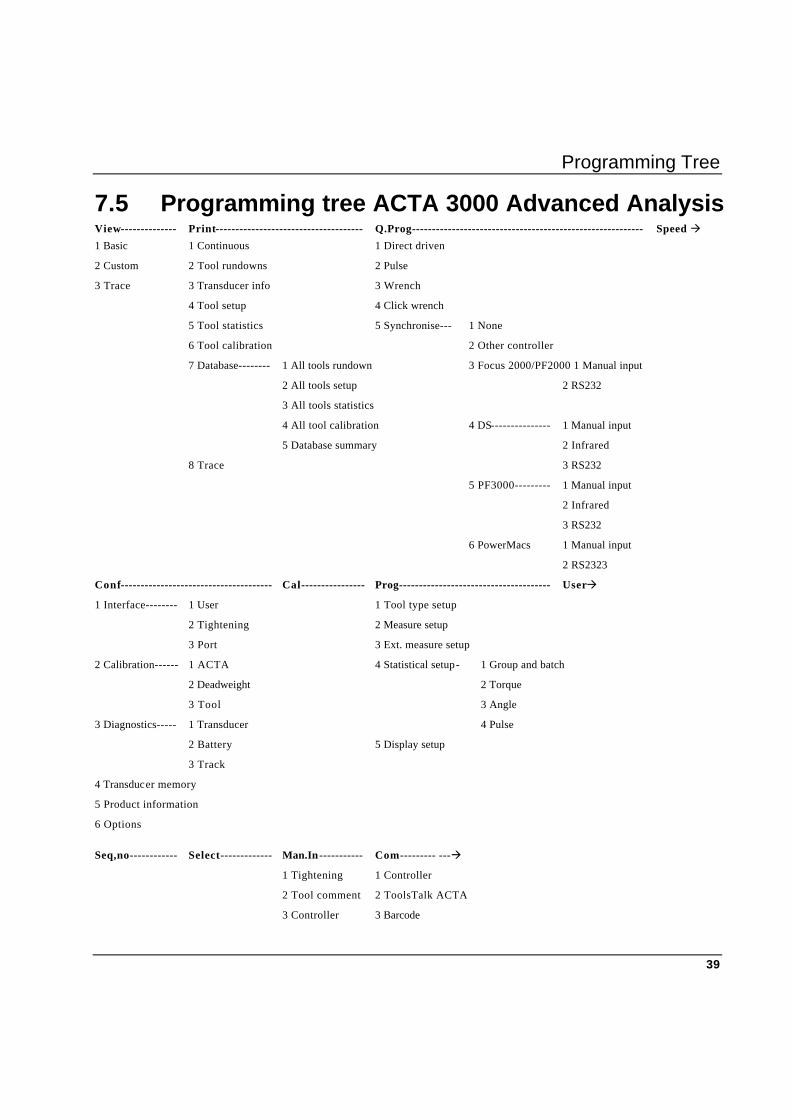
7.5 Programming tree ACTA 3000 Advanced Analysis................................................... 39 8. Programming the ACTA 3000.............................................................................................41
8.1 General ........................................................................................................................ 41
8.2 Ready to program........................................................................................................ 41
8.3 Configuration (Conf.)................................................................................................... 42 8.3.1 User interface .................................................................................................. 44 8.3.2 Tightening operation interface ........................................................................ 45 8.3.3 Port Interface................................................................................................... 49 8.3.4 Calibration ....................................................................................................... 50 8.3.5 Diagnostics ...................................................................................................... 51 8.3.6 Transducer memory ........................................................................................ 51 8.3.7 Product information......................................................................................... 52 8.3.8 Options ............................................................................................................ 53
8.4 Quick Programming (Q.Prog.).................................................................................... 53
8.5 Calibration (Cal.) ......................................................................................................... 53 8.5.1 Setting up your non-Atlas Copco memory type transducer............................ 53
8.6 Database (Datab.) ........................................................................................................ 55 8.6.1 New Tool.......................................................................................................... 55 8.6.2 Select Tool....................................................................................................... 56 8.6.3 Delete Tool...................................................................................................... 57 8.6.4 Clear all measure ments................................................................................... 58 8.6.5 Backup tool...................................................................................................... 58
8.7 Select Tool (Select) ..................................................................................................... 59
8.8 Program (Prog.)........................................................................................................... 60 8.8.1 Tool type setup................................................................................................ 63 8.8.2 Meas urement setup ........................................................................................ 66 8.8.3 Extended Measurement Setup ....................................................................... 67 8.8.4 Statistical setup................................................................................................ 69 8.8.5 Display setup ................................................................................................... 74
8.9 Speed (Speed).............................................................................................................. 79
8.10 User (User).................................................................................................................. 79
8.11 Sequence number (Seq. No.)....................................................................................... 80
8.12 View (View).................................................................................................................. 80
8.13 Manual input (Man.In) ................................................................................................ 81
8.14 Communication (Com.) ............................................................................................... 82

Contents
5
8.15 Parameters (Param.).................................................................................................... 84
8.16 Analyse (A.lyse) .......................................................................................................... 85 8.16.1 To Zoom in....................................................................................................... 85 8.16.2 To Zoom out .................................................................................................... 85 8.16.3 Adjust position................................................................................................. 86 8.16.4 Save trace ........................................................................................................ 86
8.17 Print (Print).................................................................................................................. 87 8.17.1 To select a print command .............................................................................. 88
8.18 Statistics (Stat.)............................................................................................................ 89 8.18.1 All Tightening operations ................................................................................ 91 8.18.2 Statistics torque ............................................................................................... 91 8.18.3 Statistics Angle ................................................................................................ 93 8.18.4 Statistic no. of Pulses....................................................................................... 94 8.18.5 History ............................................................................................................. 96
9. Measuring Strategies.............................................................................................................99 9.1 General ........................................................................................................................ 99
10. Measurement Results ..........................................................................................................103 10.1 General ...................................................................................................................... 103
10.2 Basic Measurement Window.................................................................................... 103
10.3 Custom Measurement Window ................................................................................ 105
10.4 Trace Measurement Window.................................................................................... 108
10.5 Batch Result window................................................................................................. 111 10.5.1 Within Limits ................................................................................................. 112 10.5.2 Outside Limits ............................................................................................... 112
11. Calibration ...........................................................................................................................113 11.1 Calibrating the ACTA 3000 ...................................................................................... 113
11.2 Calibrating Transducers with the ACTA 3000......................................................... 115 11.2.1 Calibration ..................................................................................................... 116 11.2.2 Linearity check.............................................................................................. 117 11.2.3 Saving and printing the new calibration value ............................................... 118
11.3 Tool calibration.......................................................................................................... 120 11.3.1 Non-controlled tool calibration...................................................................... 122 11.3.2 Other controller calibration........................................................................... 123 11.3.3 DS calibration................................................................................................. 124 11.3.4 Power Focus 2000 calibration ....................................................................... 126 11.3.5 Power Focus 3000 calibration ....................................................................... 127 11.3.6 PowerMac calibration.................................................................................... 129 11.3.7 Example, how to perform a calibration.......................................................... 130

Contents
6
12. Printouts from the ACTA 3000..........................................................................................133 12.1 General ...................................................................................................................... 133
12.2 Tool Rundowns .......................................................................................................... 135
12.3 Transducer Info ......................................................................................................... 136
12.4 Tool Setup ................................................................................................................. 137
12.5 Tool Statistics ............................................................................................................ 138 12.5.1 Page 1 ............................................................................................................ 138 12.5.2 Page 2 ............................................................................................................ 139
12.6 All Tool Rundowns .................................................................................................... 140
12.7 All Tool Set-ups......................................................................................................... 140
12.8 All Tool Statistics ...................................................................................................... 140
12.9 Tool calibration.......................................................................................................... 141
12.10 Database Summary .................................................................................................... 142
12.11 Trace.......................................................................................................................... 143 13. ToolsTalk ACTA.................................................................................................................145
13.1 General ...................................................................................................................... 145
13.2 The Tool Database .................................................................................................... 146
13.3 The Supplier Database .............................................................................................. 147
13.4 The Tightening Database.......................................................................................... 148 13.4.1 Tightening operation Traces......................................................................... 149 13.4.2 Tightening Statistics ...................................................................................... 150
13.5 Automatic Calibration and Maintenance Reminder................................................. 151
13.6 Program your ACTA 3000 ........................................................................................ 152
13.7 More About ToolsTalk ACTA ................................................................................. 152 14. Guide to Statistics ................................................................................................................153
14.1 General ...................................................................................................................... 153
14.2 How to estimate the variation................................................................................... 155
14.3 Capability studies ...................................................................................................... 157 14.3.1 Six-Sigma Improvement Program ................................................................. 158
14.4 Control charts............................................................................................................ 159 14.4.1 Using control charts ...................................................................................... 160 14.4.2 X-bar charts ................................................................................................... 161 14.4.3 R charts.......................................................................................................... 162
15. Technical Specifications ......................................................................................................163 15.1 Dimensions and Weights........................................................................................... 163

Contents
7
15.2 Electrical.................................................................................................................... 163
15.3 Battery....................................................................................................................... 163 15.3.1 Charging ........................................................................................................ 163
15.4 Connectors ................................................................................................................ 164 15.4.1 Transducer Pin Description .......................................................................... 164
15.5 Barcode Reader........................................................................................................ 165
15.6 Default Setups ........................................................................................................... 166 15.6.1 New ACTA 3000 ........................................................................................... 166 15.6.2 Direct Driven Tool ........................................................................................ 167 15.6.3 Pulse Tool...................................................................................................... 169 15.6.4 Wrench........................................................................................................... 171 15.6.5 Click Wrench................................................................................................. 173 15.6.6 Synchronise.................................................................................................... 175
16. Maintenance.........................................................................................................................195 16.1 Cleaning..................................................................................................................... 195
16.2 Service ....................................................................................................................... 195
16.3 Software Upgrade ...................................................................................................... 195 17. Accessories, Parts ................................................................................................................197
17.1 Accessories ............................................................................................................... 197

Safety Instructions
9
1. Safety Instructions Important All locally legislated rules with regard to installation, operation and maintenance must be observed at all times.
Warning! § When using electrical equipment, basic precautions should always be taken, including the
following:
§ Read all instructions before you begin using the equipment.
§ Before operating the equipment, please make sure that the operating voltage (indicated on the type plate on the base of the unit) is identical to the voltage of your local power supply.
§ When replacing the battery, always disconnect the equipment from the mains by unplugging it.
§ The unit is equipped with an internal fan to reduce the build-up of heat. However, the unit should only be used in an area where there is adequate ventilation and it must be kept away from sources of excessive heat (radiators or other equipment which produce heat).
§ Do not expose the unit to excessive moisture (dripping or splashing water), and do not use it near water (near a wash basin or in a wet basement) or other liquids.
§ The equipment should not be subjected to continuous or excessive shocks or vibration.
§ For minimal electrical interference, use the equipment well away from possible sources of electrical noise (arc-welding equipment, etc.).
§ There are no user-serviceable parts inside the unit. Under no circumstances should you open or attempt to repair the unit. Doing so will invalidate all warranties. Refer all service needs to your local Atlas Copco Tools service personnel.
Caution Danger of explosion if a replacement battery is incorrectly connected. Replace only with the same or an equivalent type of battery recommended by the equipment manufacturer. Discard used batteries according to the manufacturer’s instructions.


System Overview
11
2. System Overview 2.1 General Introducing the ACTA 3000; combining premium tightening analysis functionality with integrated tools management and SPC in a compact, portable and extremely user-friendly configuration. The ACTA 3000 is available in three different versions to cater for all needs: § Basic § Quality Control (QC) § Advanced Analysis (AA).
2.1.1 ACTA 3000 Basic
The ACTA 3000 Basic measures torque and angle on direct driven, residual torque and pulse tools, and counts the number of pulses on pulse tools. Basic is the entry level version designed for simple torque checking in a repair shop or directly on the production/assembly line. It has the following functionality:
§ Measures Torque / Angle / Pulses
§ Mean / 3 Sigma
§ Single Memory Position
§ Flash Memory
§ Auto Cal. and Self Test
§ Auto Cal. on AC Memory Transducers
§ Print Statistics
§ Transducer database for non-Atlas Copco transducers.
2.1.2 ACTA 3000 Quality Control
Quality Control is the next step up from Basic. It includes a database with sufficient memory capacity to organise and store more than 500 tools or up to 9,000 tool tightening operations. It also includes advanced statistical functions and is ToolsTalk ACTA compatible.

System Overview
12
It incorporates all the following functionality (including all features of Basic):
§ CP / CPK
§ Real Time SPC
§ Databases for Tools, Measurements and History
§ ToolsTalk ACTA Compatible
§ Print SPC - for an entire tool / tool tightening database
§ Tool calibration.
2.1.3 ACTA 3000 Advanced Analysis
Advanced Analysis is the top of the range version. It employs a detailed graphic display function to allow you to perform advanced analysis of the tightening characteristics of various tools or joints.
It has the following functionality (including all features of Basic and Quality Control):
§ Tightening Traces with Zoom-In
§ Print Traces
The ACTA 3000 can easily be upgraded thanks to its flash memory, which allows software updates straight from a PC.
All ACTA 3000 versions have an integral battery that ensures up to 3.5 hours of continuous use for convenient tests on the production/assembly line.
The ACTA 3000 is also equipped with a PC port allowing quick upgrades and PC integration through ToolsTalk ACTA, as well as a Printer Port and an Analogue Output to further enhance documentation capability and quality analysis.
Setup is easily accomplished. The Atlas Copco memory transducers communicate calibration data instantly to the ACTA 3000 at startup. Just connect and start measuring.
The programming logic is based on read-at-a-glance menus and all programmable parameters are divided into logical blocks with pop-up menus.
The ACTA 3000 also has a quick programming function to minimise programming work when performing simple torque checks.

System Overview
13
2.1.4 ToolsTalk ACTA
In addition to its built-in functionality, the ACTA 3000 Quality Control and Advanced Analysis can be supplemented with the PC program ToolsTalk ACTA to create a complete quality management system.
With ToolsTalk ACTA you have a complete tool database, tightening database and supplier database for easy storage and access to all the information you might need about your tools, along with traces* and detailed statistical data.
You are also able to attach maintenance and service instructions for all your tools and keep a record of work in progress. Best of all, ToolsTalk ACTA can even keep track and remind you of maintenance and service intervals. Read more in the ToolsTalk ACTA section.
*ACTA 3000 Advanced Analysis version required

Installation and startup
15
3. Installation and startup 3.1 Out of the Box When purchasing any version of ACTA 3000, the following should be included:
§ V AC Power Supply Cable
§ Manual /ASL
§ Calibration Certificate.
Please keep the calibration certificate as it might be useful ID when servicing your ACTA 3000 in the future.
3.1.1 Installation
The ACTA 3000 is a stand-alone portable product. Therefore, no particular installation is necessary. Simply follow the safety instructions and observe the following recommendations:
§ Place the ACTA 3000 on a firm, flat surface or hold it securely in your hand
§ Connect your Atlas Copco memory transducer
§ Connect the power supply cable
§ Start the ACTA 3000 by pressing and holding the ‘On’ button until the buzzer sounds.
The first time you charge the battery, please charge it for 12 hours and then use the ACTA 3000 in battery mode until the battery is totally drained.
The ACTA 3000 features an internal charger which can be used during charging if connected to a V AC outlet.

Installation and startup
16
Power Supply Port Transducer Port
To install other accessories, such as a printer, oscilloscope etc., or find out how to connect them to a PC, see the connector diagram in the Technical Information section.
Startup When you start the ACTA 3000, the following will appear in the display dialog box:
• The Atlas Copco logo flashes
• The Measurement dialog box appears
• The Calibration dialog box flashes (if an Atlas Copco memory transducer is connected)
• The Measurement dialog box resumes.
The ACTA 3000 initialises and performs a self-test. The calibration dialog box appears in order to indicate that the ACTA 3000 is communicating with the Atlas Copco memory transducer and performing an automatic setup. It reads the transducer’s serial number and calibration data, which it stores in its memory.
Note! The ACTA 3000 can operate with most types of transducer. If you use an Atlas Copco non-memory transducer or other brand, refer to the Technical Specifications section on how to set up your transducer before continuing with Quick Programming in the next section.
Connector Panel For a complete technical specification of the connectors, see the Technical Specifications section
Quick Programming
17
4. Quick Programming 4.1 General
This section focuses on how you can start measuring in minutes with the Quick Programming function using Atlas Copco Torque/Angle memory transducers.
All versions of the ACTA 3000 feature a Quick Programming function that allows you to set up a measurement session without extensive programming. It is ideal with the ACTA 3000 Basic or for quick and simple torque checks.
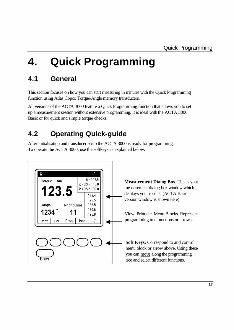
4.2 Operating Quick-guide After initialisation and transducer setup the ACTA 3000 is ready for programming. To operate the ACTA 3000, use the softkeys as explained below.
Measurement Dialog Box. This is your measurement dialog box window which displays your results. (ACTA Basic version window is shown here)
View, Print etc. Menu Blocks. Represent programming tree functions or arrows.
Soft Keys. Correspond to and control menu block or arrow above. Using these you can move along the programming tree and select different functions. Enter
Quick Programming
18
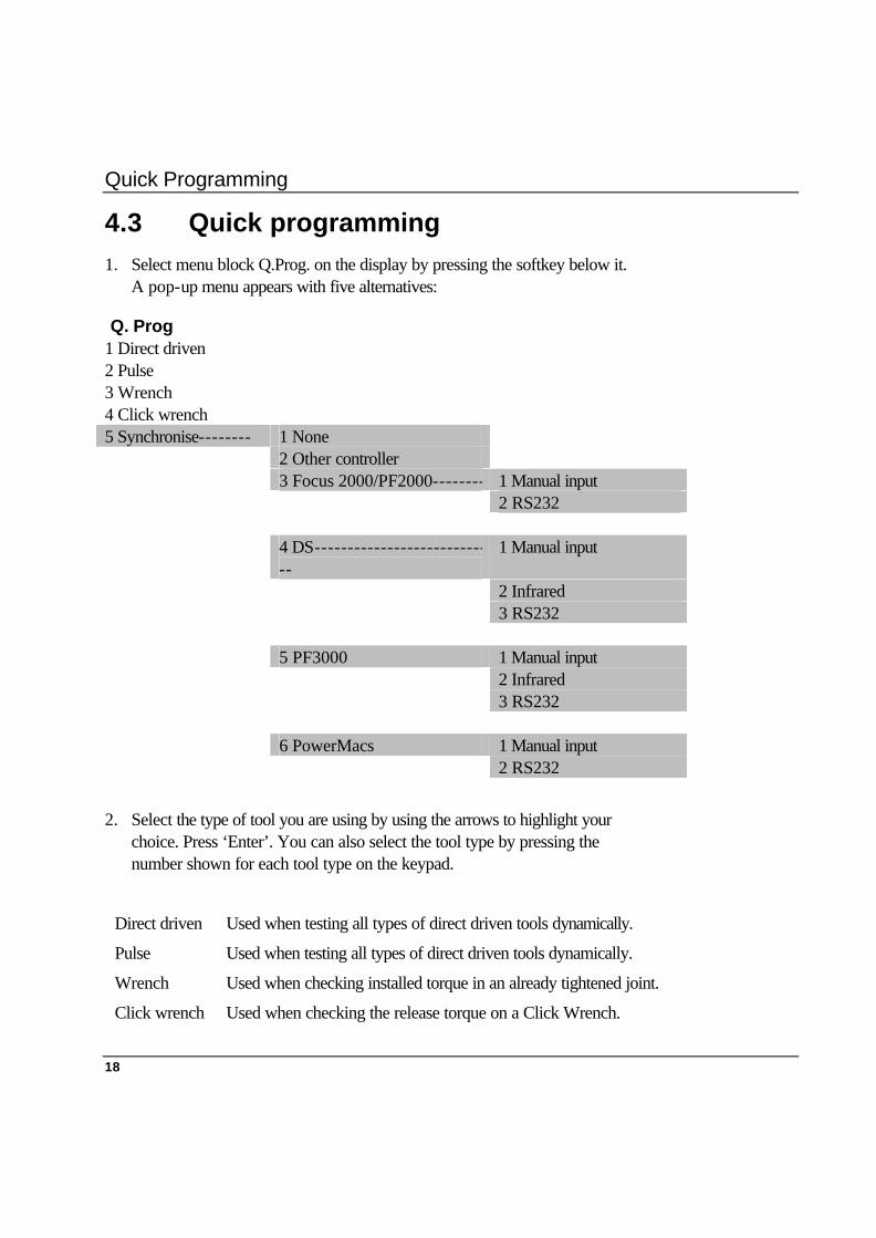
4.3 Quick programming 1. Select menu block Q.Prog. on the display by pressing the softkey below it.
A pop-up menu appears with five alternatives:
Q. Prog 1 Direct driven 2 Pulse 3 Wrench 4 Click wrench 5 Synchronise-------- 1 None 2 Other controller 3 Focus 2000/PF2000-------- 1 Manual input 2 RS232 4 DS--------------------------
-- 1 Manual input
2 Infrared 3 RS232 5 PF3000 1 Manual input 2 Infrared 3 RS232 6 PowerMacs 1 Manual input 2 RS232
2. Select the type of tool you are using by using the arrows to highlight your choice. Press ‘Enter’. You can also select the tool type by pressing the number shown for each tool type on the keypad.
Direct driven Used when testing all types of direct driven tools dynamically.
Pulse Used when testing all types of direct driven tools dynamically.
Wrench Used when checking installed torque in an already tightened joint.
Click wrench Used when checking the release torque on a Click Wrench.
Quick Programming
19
3. You are now asked if you want to use default programming.
Note! If Pulse is selected, an input menu appears in the ACTA display asking for the filter frequency. Enter the frequency and press ‘Enter’.
If Wrench is selected, a list menu appears where you can select between Peak torque or Static installed torque.
Read more about strategies in Chapter 0.
Note!
Shaded areas are only available in QC & AA.
4. When using “Synchronise”, the ACTA 3000 will be programmed to measure the torque similar to the controller. After each tightening operation the ACTA 3000 will either ask the operator for or read the tightening values directly from the controller, depending on the programming (manual input, infrared or RS232).
Note!
If “none” or “other” controller is selected, a pop-up menu appears where the type of tool can be selected. For “none” controlled tool an input menu appears requesting the target torque. For “other” controller tool the calibration torque should be input. Select Pulse tool and another question appears requesting the filter frequency. Select Wrench and another question appears requesting the measure strategy.
Note!
If infrared or RS232 is selected, the ACTA 3000 will try to communicate with the controller and read the settings. Therefore, make sure that this is possible, either by connecting an Atlas Copco serial cable between the controller and the ACTA 3000 (RS232) or by pointing the ACTA 3000 towards the controller display (infrared).
DS infrared:
DS drive will start to blink “- -“, “ -- “. Press the ‘Enter’ button (the arrow) until the display starts to blink “Ir”.
PF3000 Compact infrared:
PF drive will start to blink “-Ir-“, “ “. Press the ‘Enter’ button (the arrow) until the display starts blinking “-Ir-“, “ Ir “.
Quick Programming
20
PF3000 Graph infrared:
A text window on the screen says:
“IR connect requested from ACTA 3000 on local channel 0. Press ‘OK’ to acknowledge, wait or cancel to refuse.”
Press ‘OK’ on the PF. A new message appears:
“IR connect requested from ACTA 3000 on local channel 0. Press ‘OK’ to acknowledge, wait or cancel to refuse.”
The selected tool in the ACTA 3000 will then be programmed with the settings from the controller.
Note! If Focus 2000/PF2000 automatic tool calibration (Q.Prog.-5-3-2) is selected, an input menu requesting the unit ID appears in the ACTA 3000 display. Enter the controller unit ID and press ‘Enter’.
5. Use the arrows again to highlight OK and press ‘Enter’ or simply press the ‘OK’ button on the keypad.
6. Another dialog box flashes confirming that default programming is now being used. Programming is complete – you are ready to start measuring.

Quick Programming
21
4.4 Your Measurement Results using Quick Programming
10 11 7 12 1
1. Number of tightenings 7. Name of tool 2. X-bar 8. Number of pulses 3. Confidence interval neg. 9. Last five tightenings 4. Confidence interval pos. 10. Power left in battery 5. Measured torque 11. Communication 6. Measured angle 12. Filter frequency
Start measuring.
After a few tightening operations the display should appear as shown below.
Note!
The symbol to the right of the battery symbol indicates the type of communication selected (ToolsTalk, Focus 2000/PF2000 serial, PF 3000 serial or infrared, DS serial or DS infrared). This symbol is only displayed in QC & AA ACTA 3000 (Basic ACTA 3000 does not have the ability to communicate). Display Parameter Explanation
1. Number of tightening operations The number of tightening operations that have been performed.
2. X-bar The average of all the measurements that have been performed. Located in the memory.
5 6
2 3 4 9 8

Quick Programming
22
Display Parameter Explanation
3. Confidence interval neg. The lowest possible value with a confidence of more than 99 %.
4. Confidence interval pos. The highest possible value with a confidence of more than 99 %.
5. Measured torque The torque value.
6. Measured angle The current angle value. If there is no angle signal from the transducer, this field will be empty.
7. Name of tool If a tool has been selected from the database, the name is shown in the header. This is not possible if the ACTA 3000 version is Basic. In that case this field is always empty
8. Number of pulses If a Pulse tool is selected, this field shows the number of pulses for the last tightening operation. Otherwise this field is empty.
9. Last five tightening operations The last five tightening operations entered in the memory. With each new tightening operation the result is displayed at the top and the older values move down. When the memory is cleared, this field is empty.
10. Power left in battery This indicates how much power there is left in the battery. When the battery indicator is completely white the battery is fully charged and when the battery indicator is completely black, less than 8% of the battery power remains. If the battery is removed or replaced, this symbol remains empty until the battery has been fully charged/recharged.
11. Communication Information about the current communication settings.
12. Filter frequency Filter frequency, visible for Pulse tool.

Keys and indicators
23
5. Keys and Indicators 5.1 Front Panel 5 6 7
1. OK 6. Enter 2. NOK 7. OK 3. n x OK 8. Shift 4. Battery 9. Clear 5. On/Off 10. Softkeys
The front panel layout is the same for all versions of the ACTA 3000. Apart from the display, it features LED indicators, softkeys and an alpha-numeric keypad.
For a detailed description on the LED indicators, the functionality of the softkeys and the alpha-numeric keypad, see the next page.
OK
NOK
n x OK
Enter
Enter
2 31
4
9
0
87
65
OK .
Shift
Cl
ABC DEF GHI
JKL MNO PQR Clear All
STU VWX YZ
1 2 3 4 8 9 6
10
Keys and Indicators
24
5.1.1 Status (LED) Indicators
1. OK Lights up when the result of a tightening operation falls within all the specified limits. The signal will be active for 10 seconds or until the next tightening operation is initiated.
2. NOK Lights up when the result of a tightening operation falls outside any of the specified limits. The signal will be active for 10 seconds or until the next tightening operation is initiated.
3. n x OK Flashes three times when the number of tightening operations corresponds to the present number of tightening operations programmed in the ACTA 3000. (Batch size).
4. Battery
§ Red ACTA 3000 needs to be charged.
§ Flashing green Charging just started. 110 / 220 V on but battery not connected. Something wrong with charging circuits.
§ Constant green ACTA 3000 charging
§ Off If 110 / 220 V connected, battery fully charged If 110 / 220 V not connected, ACTA 3000 uses the battery.
Function Keys
5. On/Off Button To start the ACTA 3000, press the button and hold it down for approximately three seconds. To shut it off, press the button once.
6. Enter ‘Enter’ is used to select an option and verify inputs in the programming blocks.
7. OK ‘OK’ is used to activate inputs in the programming blocks.
Keys and Indicators
25
8. Shift Pressing the ‘Shift’ button activates the letters above each numeric key. Keep pressing the numeric key to find the desired letter.
9. Cl The ‘Clear’ button is used to erase old values in the programming blocks or to delete the latest result of the current tightening measurement. Note! When the ‘Shift’ and ‘Clear’ buttons are pressed at the same time, all results of the current tightening torque measurements will be erased or when editing data in an input dialog box all data will be removed.
10. Display Softkeys (Blank) Each key corresponds to various blocks of softkey text (programming tree menus) or arrows in the display.

Measurement Dialog boxes
27
6. Measurement Dialog boxes 6.1 General The ACTA 3000 features a large back-lit 72 x 96 mm display with a Dialog box-like interface to allow accurate measurement readings and simple usage. The ACTA 3000 also features a power-save function that de-activates the back-lighting on the ACTA 3000 if it is not used for 30 seconds. This is to save the battery and works only when the ACTA 3000 is powered from the battery.
6.2 The Different Measurement Dialog boxes The measurement dialog box can be defined as your active dialog box during measurements, displaying your results. There is a maximum of three different measurement dialog boxes (Basic, Custom and Trace), depending on the version of ACTA 3000. The bottom row on each measurement dialog box also displays the main parameters of the programming tree organised in menu blocks. Each measurement dialog box has its own functionality and therefore its own programming tree (menu block) setup. Shown below and on the following pages are the measurement dialog boxes for the different versions of the ACTA 3000, as well as a chart of the measurement dialog box and menu block setup combinations for each version of the ACTA 3000.
Measurement Dialog boxes
28
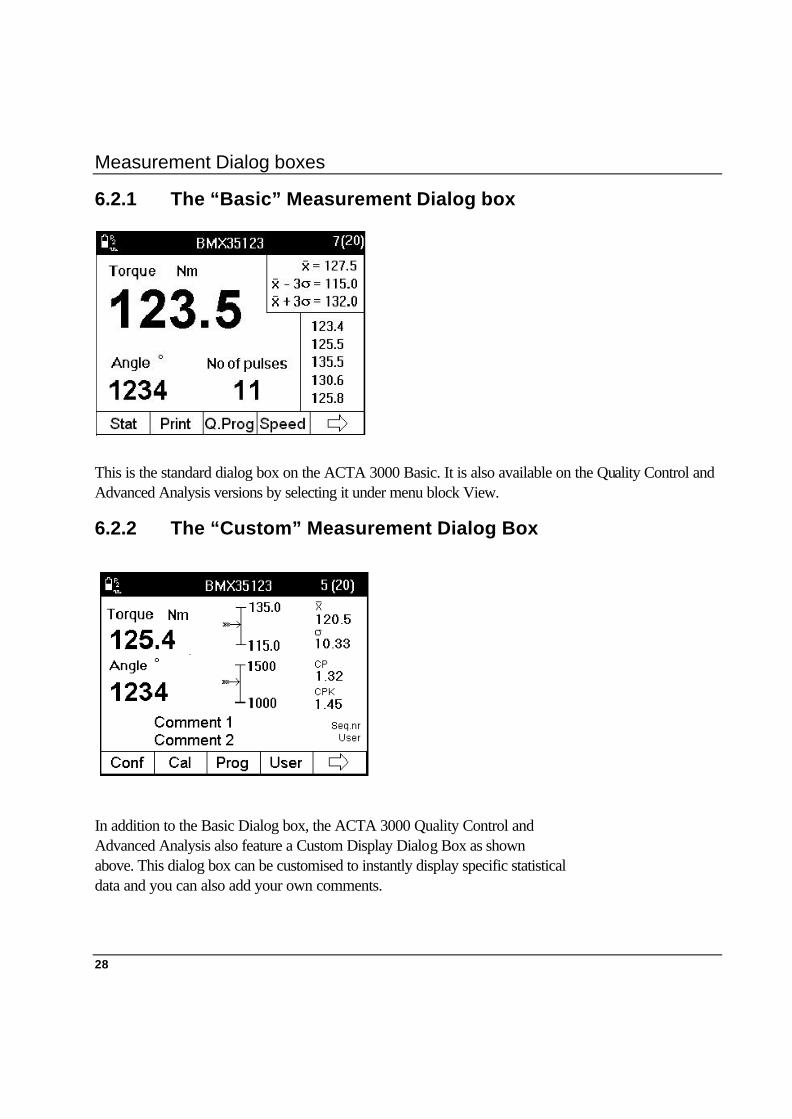
6.2.1 The “Basic” Measurement Dialog box
This is the standard dialog box on the ACTA 3000 Basic. It is also available on the Quality Control and Advanced Analysis versions by selecting it under menu block View.
6.2.2 The “Custom” Measurement Dialog Box
In addition to the Basic Dialog box, the ACTA 3000 Quality Control and Advanced Analysis also feature a Custom Display Dialog Box as shown above. This dialog box can be customised to instantly display specific statistical data and you can also add your own comments.
Measurement Dialog boxes
29
During measurements it is possible to switch between the Basic dialog box and Custom dialog box at any time.
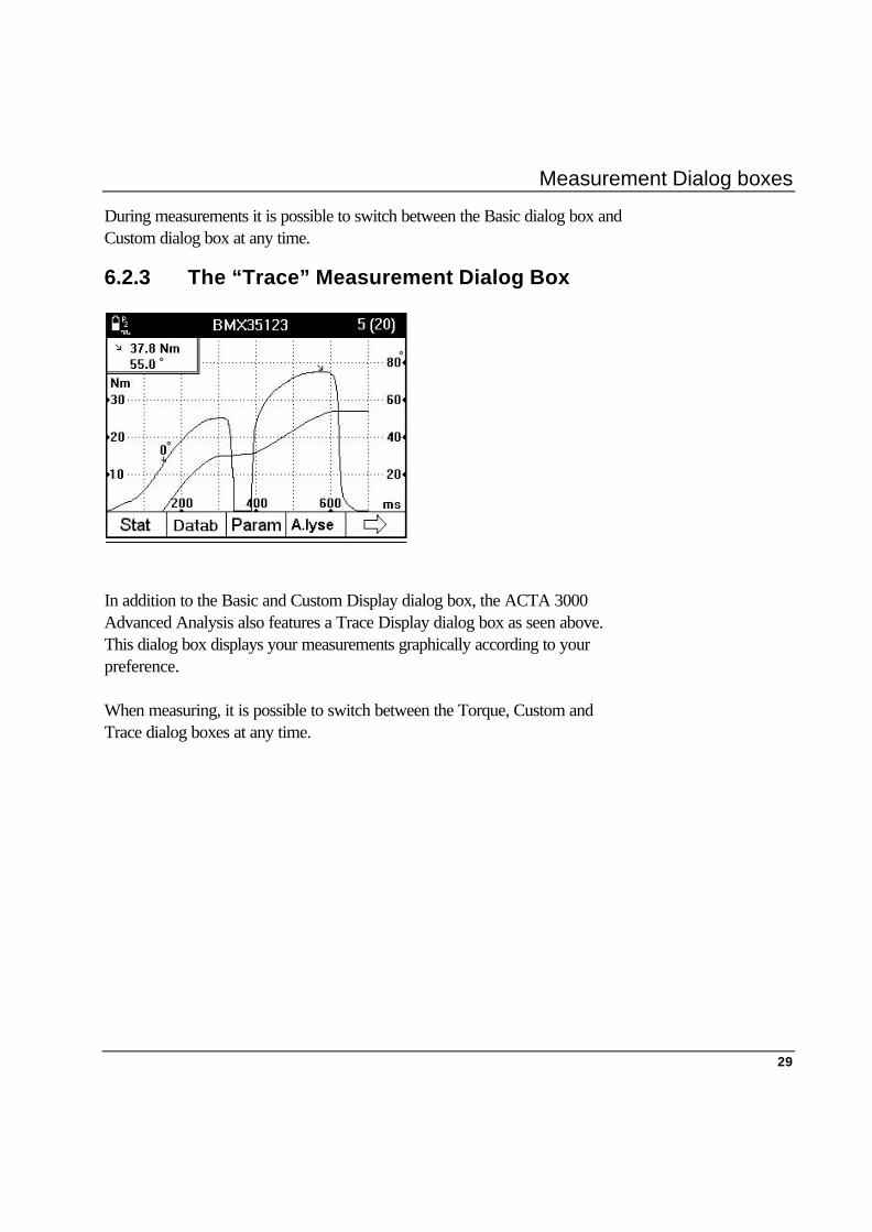
6.2.3 The “Trace” Measurement Dialog Box
In addition to the Basic and Custom Display dialog box, the ACTA 3000 Advanced Analysis also features a Trace Display dialog box as seen above. This dialog box displays your measurements graphically according to your preference. When measuring, it is possible to switch between the Torque, Custom and Trace dialog boxes at any time.

Measurement Dialog boxes
30
6.3 Measurement Dialog box / Menu Block Setup Combinations
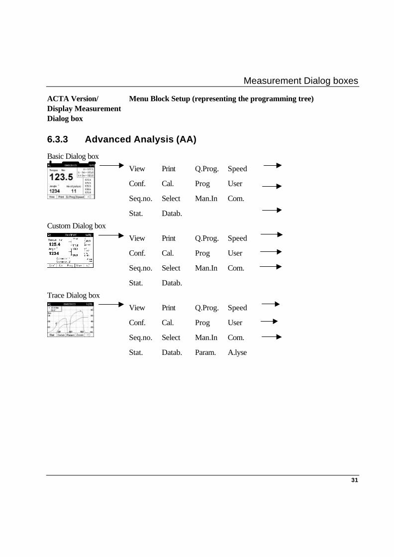
ACTA Version/ Display Measurement Dialog box
Menu Block Setup (representing the programming tree)
6.3.1 Basic
Basic Dialog box Stat.. Print Q.Prog.. Speed
Conf.. Cal.. Prog..
6.3.2 Quality Control (QC)
Basic Dialog box Stat.. Print Q.Prog.. Speed
Conf. Cal. Prog. User
Seq.no. Select Man.In Com.
Custom Dialog box Stat.. Print Q.Prog.. Speed
Conf. Cal. Prog. User
Seq.no. Select Man.In Com.
Measurement Dialog boxes
31
ACTA Version/ Display Measurement Dialog box
Menu Block Setup (representing the programming tree)
6.3.3 Advanced Analysis (AA)
Basic Dialog box
View Print Q.Prog. Speed
Conf. Cal. Prog User
Seq.no. Select Man.In Com.
Stat. Datab.
Custom Dialog box
View Print Q.Prog. Speed
Conf. Cal. Prog User
Seq.no. Select Man.In Com.
Stat. Datab.
Trace Dialog box
View Print Q.Prog. Speed
Conf. Cal. Prog User
Seq.no. Select Man.In Com.
Stat. Datab. Param. A.lyse


Programming Tree
33
7. Programming Tree 7.1 General
On the following pages you will see the programming tree for the ACTA 3000 Basic, Quality Control and Advanced Analysis, displaying the full functionality of each version.
We will now describe how to navigate through the programming tree, how you find and select specific functions (parameters) and how you input values. In other words, how to prepare to program your ACTA 3000.
7.2 Using the programming tree Let us examine the programming tree more closely and look at some of the definitions that are frequently used when describing it and which will allow you to navigate with ease.
7.2.1 Menu Blocks
As you can see, the programming tree consists of a maximum of 15 main menus (ACTA 3000 Advanced Analysis). These menus / menu blocks are located at the bottom of the ACTA 3000 display as shown below.
The menu blocks are operated using the blank softkeys placed below the display. Each softkey is used to select an individual menu block (programming tree function) and you use the arrow to scroll through the main menus.
In the Programming section that follows, every reference to a menu block refers to the following.
Programming Tree
34
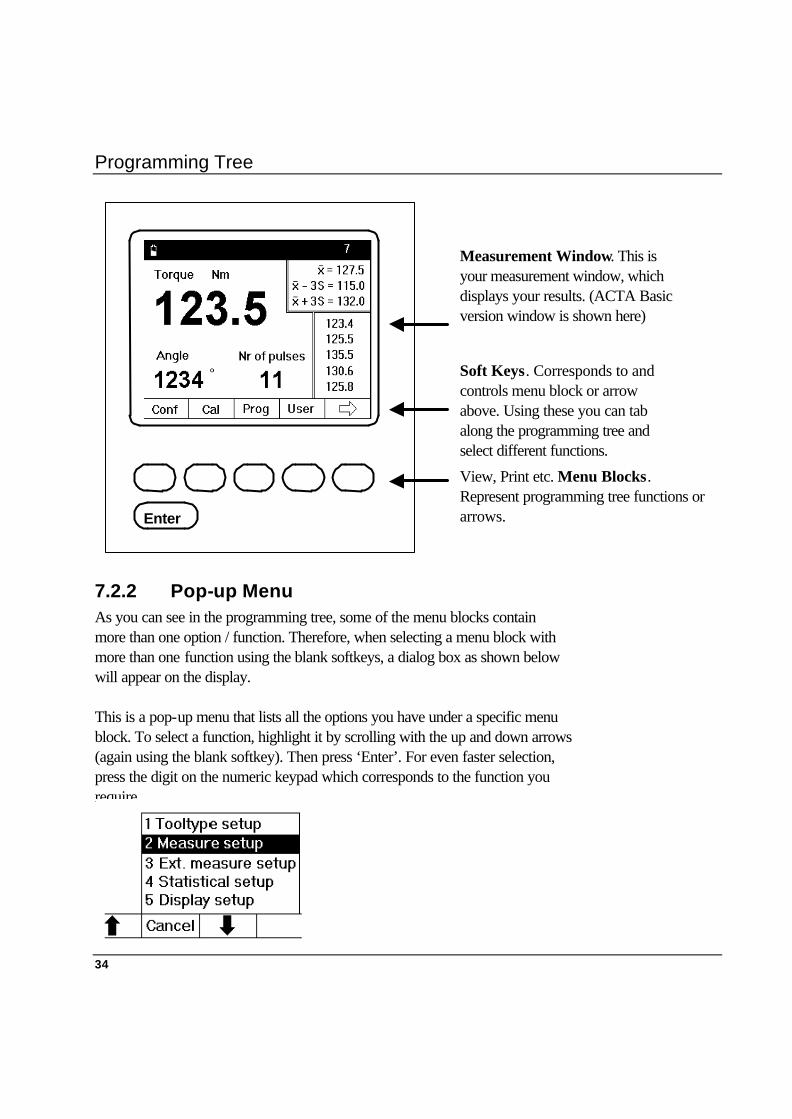
7.2.2 Pop-up Menu As you can see in the programming tree, some of the menu blocks contain more than one option / function. Therefore, when selecting a menu block with more than one function using the blank softkeys, a dialog box as shown below will appear on the display. This is a pop-up menu that lists all the options you have under a specific menu block. To select a function, highlight it by scrolling with the up and down arrows (again using the blank softkey). Then press ‘Enter’. For even faster selection, press the digit on the numeric keypad which corresponds to the function you require.
View, Print etc. Menu Blocks. Represent programming tree functions or arrows. Enter
Measurement Window. This is your measurement window, which displays your results. (ACTA Basic version window is shown here)
Soft Keys. Corresponds to and controls menu block or arrow above. Using these you can tab along the programming tree and select different functions.
Programming Tree
35
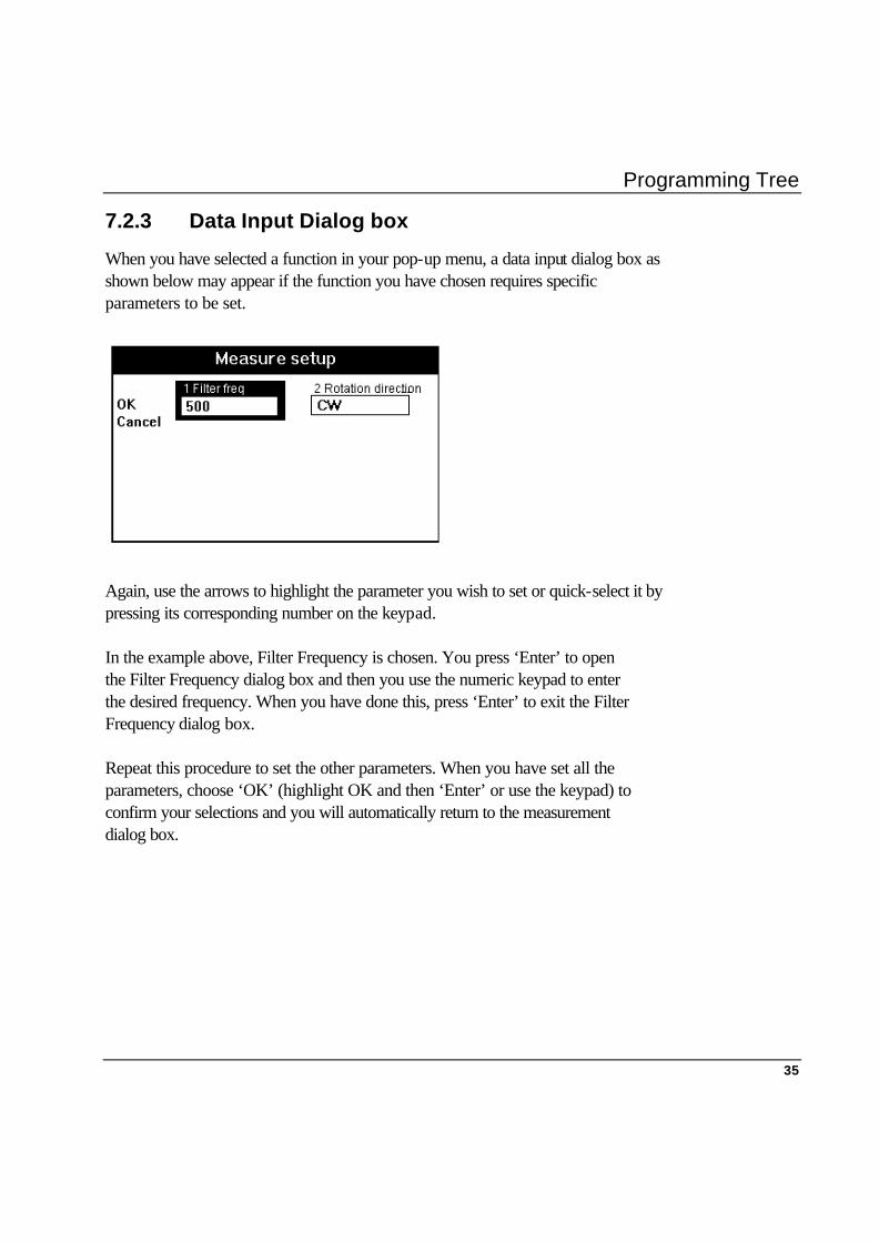
7.2.3 Data Input Dialog box
When you have selected a function in your pop-up menu, a data input dialog box as shown below may appear if the function you have chosen requires specific parameters to be set. Again, use the arrows to highlight the parameter you wish to set or quick-select it by pressing its corresponding number on the keypad. In the example above, Filter Frequency is chosen. You press ‘Enter’ to open the Filter Frequency dialog box and then you use the numeric keypad to enter the desired frequency. When you have done this, press ‘Enter’ to exit the Filter Frequency dialog box. Repeat this procedure to set the other parameters. When you have set all the parameters, choose ‘OK’ (highlight OK and then ‘Enter’ or use the keypad) to confirm your selections and you will automatically return to the measurement dialog box.
Programming Tree
36
7.3 Programming tree ACTA 3000 Basic Stat-----------------
Print------------------------------------------
Q.Prog--------------
Speed à
1 Continuous 1 Direct driven
2 Tool rundowns 2 Pulse
3 Transducer info 3 Wrench
4 Tool setup 4 Click wrench
Conf-------------------------------------------
Cal-------------------
Prog-------------------------------------------
1 Interface----------
1 User 1 Tool type setup
2 Tightening 2 Measure setup
3 Port 3 Ext. measure setup
2 Calibration-------
1 ACTA
2 Deadweight
3 Diagnostics------
1 Transducer
2 Battery
3 Track
4 Transducer memory
5 Product information
6 Options
Programming Tree
37
7.4 Programming tree ACTA 3000 Quality Control View-------------- Print------------------------------------- Q.Prog---------------------------------------------------------- Speed à
1 Basic 1 Continuous 1 Direct driven
2 Custom 2 Tool rundowns 2 Pulse
3 Transducer info 3 Wrench
4 Tool setup 4 Click wrench
5 Tool statistics 5 Synchronise--- 1 None
6 Tool calibration 2 Other controller
7 Database-------- 1 All tools rundown 3 Focus 2000/PF2000 1 Manual input
2 All tools setup 2 RS232
3 All tools statistics
4 All tools calibration 4 DS--------------- 1 Manual input
5 Database summary 2 Infrared
3 RS232
5 PF3000--------- 1 Manual input
2 Infrared
3 RS232
6 PowerMacs----- 1 Manual input
2 RS232
Conf-------------------------------------- Cal---------------- Prog-------------------------------------- Userà
1 Interface-------- 1 User 1 Tool type setup
2 Tightening 2 Measure setup
3 Port 3 Ext. measure setup
2 Calibration------ 1 ACTA 4 Statistical setup- 1 Group and batch
2 Deadweight 2 Torque
3 Tool 3 Angle
3 Diagnostics----- 1 Transducer 4 Pulse
2 Battery 5 Display setup
3 Track
4 Transducer memory
5 Product information
6 Options
Seq,no------------ Select------------- Man.In---------- Com--------- -à
1 Tightening 1 Controller
2 Tool comment 2 ToolsTalk ACTA
3 Controller 3 Barcode

Programming Tree
38
Stat-------------------------------------------------------------- Datab-------------------------------------
1 All tightenings 1 New tool
2 Statistics torque 2 Select tool
3 Statistics angle 3 Delete tool- 1 Selected tool
4 Statistics no. of pulses 2 All tools
5 History---------- 1 Torque---------- 1 Table 4 Clear all measurements
2 X graph 5 Backup tool
3 R graph 6 Information
4 σ graph
2 Angle------------ 1 Table
2 X graph
3 R graph
4 σ graph
3 No. of pulses--- 1 Table
2 X graph
3 R graph
4 σ graph
Programming Tree
39
7.5 Programming tree ACTA 3000 Advanced Analysis View-------------- Print------------------------------------- Q.Prog---------------------------------------------------------- Speed à
1 Basic 1 Continuous 1 Direct driven
2 Custom 2 Tool rundowns 2 Pulse
3 Trace 3 Transducer info 3 Wrench
4 Tool setup 4 Click wrench
5 Tool statistics 5 Synchronise--- 1 None
6 Tool calibration 2 Other controller
7 Database-------- 1 All tools rundown 3 Focus 2000/PF2000 1 Manual input
2 All tools setup 2 RS232
3 All tools statistics
4 All tool calibration 4 DS--------------- 1 Manual input
5 Database summary 2 Infrared
8 Trace 3 RS232
5 PF3000--------- 1 Manual input
2 Infrared
3 RS232
6 PowerMacs 1 Manual input
2 RS2323
Conf-------------------------------------- Cal---------------- Prog-------------------------------------- Userà
1 Interface-------- 1 User 1 Tool type setup
2 Tightening 2 Measure setup
3 Port 3 Ext. measure setup
2 Calibration------ 1 ACTA 4 Statistical setup- 1 Group and batch
2 Deadweight 2 Torque
3 Tool 3 Angle
3 Diagnostics----- 1 Transducer 4 Pulse
2 Battery 5 Display setup
3 Track
4 Transducer memory
5 Product information
6 Options
Seq,no------------ Select------------- Man.In----------- Com--------- ---à
1 Tightening 1 Controller
2 Tool comment 2 ToolsTalk ACTA
3 Controller 3 Barcode
Programming Tree
40
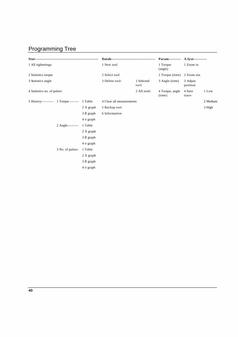
Stat----------------------------------------------------- Datab------------------------------------- Param---------- A.lyse-----------
1 All tightenings 1 New tool 1 Torque (angle)
1 Zoom in
2 Statistics torque 2 Select tool 2 Torque (time) 2 Zoom out
3 Statistics angle 3 Delete tool- 1 Selected tool
3 Angle (time) 3 Adjust position
4 Statistics no. of pulses 2 All tools 4 Torque, angle (time)
4 Save trace-
1 Low
5 History---------- 1 Torque-------- 1 Table 4 Clear all measurements 2 Medium
2 X graph 5 Backup tool 3 High
3 R graph 6 Information
4 σ graph
2 Angle--------- 1 Table
2 X graph
3 R graph
4 σ graph
3 No. of pulses- 1 Table
2 X graph
3 R graph
4 σ graph

Programming
41
8. Programming the ACTA 3000 8.1 General In this section we will explain how to use the different functions and parameters of the programming tree to program your ACTA 3000. Use the display dialog box / menu block chart and the programming tree charts to help you.
8.2 Ready to program How to program the different programming tree parameters will be described in a menu block and in the following order:
§ Configuration
§ Quick Programming
§ Calibration
§ Database
§ Select
§ Program
§ Speed
§ User
§ View
§ Manual Input
§ Seq.no
§ Parameter
§ Analyse
§ Statistics
If your ACTA 3000 version does not feature a specific menu block (depending on its functionality), simply skip that menu block and continue with the next one.
Programming
42
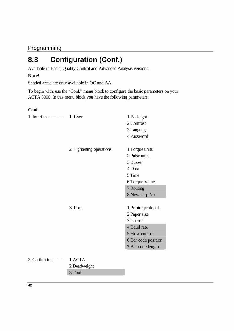
8.3 Configuration (Conf.) Available in Basic, Quality Control and Advanced Analysis versions.
Note! Shaded areas are only available in QC and AA.
To begin with, use the “Conf.” menu block to configure the basic parameters on your ACTA 3000. In this menu block you have the following parameters. Conf. 1. Interface--------- 1. User 1 Backlight 2 Contrast 3 Language 4 Password 2. Tightening operations 1 Torque units 2 Pulse units 3 Buzzer 4 Data 5 Time 6 Torque Value 7 Routing 8 New seq. No. 3. Port 1 Printer protocol 2 Paper size 3 Colour 4 Baud rate 5 Flow control 6 Bar code position 7 Bar code length 2. Calibration------ 1 ACTA 2 Deadweight 3 Tool
Programming
43
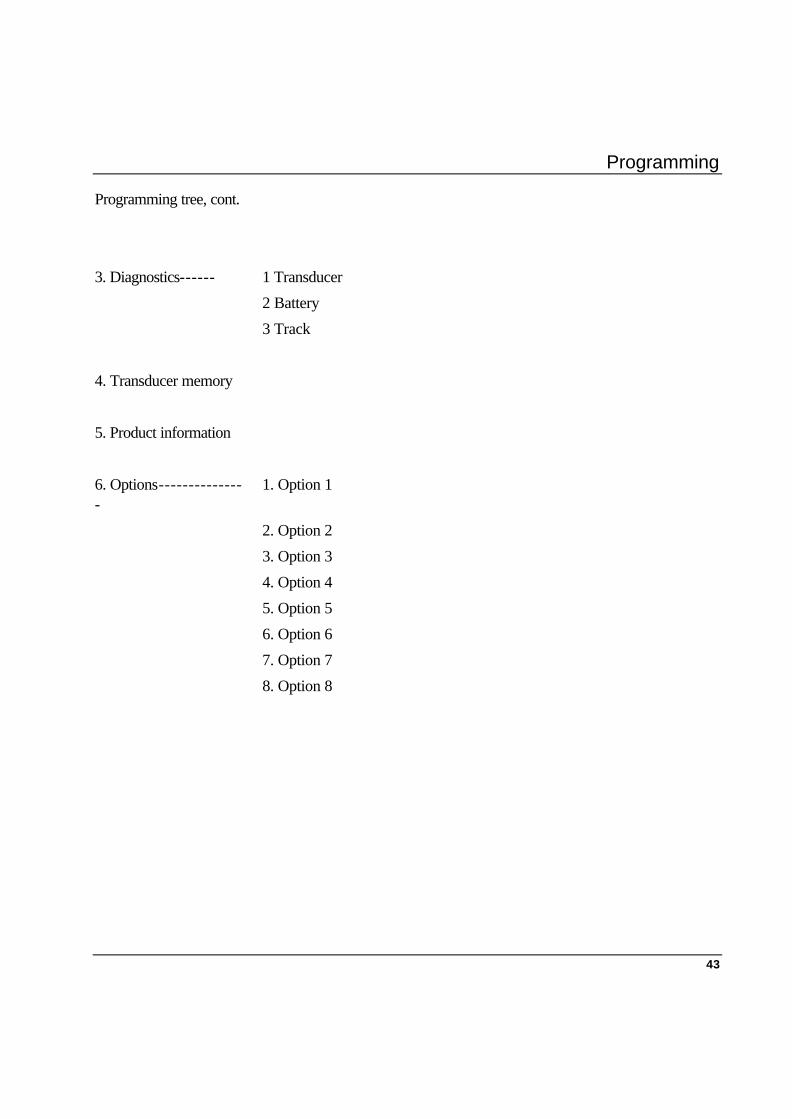
Programming tree, cont.
3. Diagnostics------ 1 Transducer
2 Battery
3 Track
4. Transducer memory
5. Product information
6. Options---------------
1. Option 1
2. Option 2
3. Option 3
4. Option 4
5. Option 5
6. Option 6
7. Option 7
8. Option 8
Programming
44
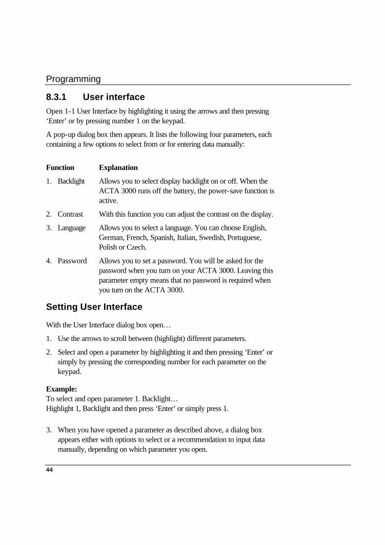
8.3.1 User interface Open 1-1 User Interface by highlighting it using the arrows and then pressing ‘Enter’ or by pressing number 1 on the keypad.
A pop-up dialog box then appears. It lists the following four parameters, each containing a few options to select from or for entering data manually:
Function Explanation
1. Backlight Allows you to select display backlight on or off. When the ACTA 3000 runs off the battery, the power-save function is active.
2. Contrast With this function you can adjust the contrast on the display.
3. Language Allows you to select a language. You can choose English, German, French, Spanish, Italian, Swedish, Portuguese, Polish or Czech.
4. Password Allows you to set a password. You will be asked for the password when you turn on your ACTA 3000. Leaving this parameter empty means that no password is required when you turn on the ACTA 3000.
Setting User Interface
With the User Interface dialog box open…
1. Use the arrows to scroll between (highlight) different parameters.
2. Select and open a parameter by highlighting it and then pressing ‘Enter’ or simply by pressing the corresponding number for each parameter on the keypad.
Example: To select and open parameter 1. Backlight… Highlight 1, Backlight and then press ‘Enter’ or simply press 1.
3. When you have opened a parameter as described above, a dialog box appears either with options to select or a recommendation to input data manually, depending on which parameter you open.

Programming
45
Example: Parameter 1. Backlight. When open, it shows On or Off.
4. Select your option within the open parameter by highlighting it and then pressing ‘Enter’ or by simply pressing its corresponding number on the keypad.
Example: Selecting Backlight On Open 1. Backlight. Then use the arrows to highlight 1. On. Then press ‘Enter’ or Open 1. Backlight. Then press number 1 on the keypad.
If you need to input data manually, use the keypad. When finished, press ‘Enter’. Now continue to set all eight parameters in the User Interface by repeating steps 1-4.
5. When you have set all the parameters to your preference, you will have to confirm your selection and then exit the User Interface dialog box.
6. To do so, use the arrows to highlight the OK sign in the top left corner and press ‘Enter’ or simply press the ‘OK’ button on the keypad.
Your selections are confirmed and the measurement dialog box returns.
If you need to exit the User Interface dialog box (or any other data input dialog box) prematurely, simply press menu block Cancel. Cancel is activated every time you select a programming tree menu block.
8.3.2 Tightening operation interface
1. Torque units In ACTA 3000 Basic, this sets the units for the torque. You can choose between: Nm, ozf.in, lbf.in, lbf.ft, kgf.m and kgf.cm. In ACTA 3000 QC & AA this parameter sets the default torque units used in Quick Programming. See Quick Programming.
2. Pulse units In ACTA 3000 Basic, this sets the units for the pulse. You can choose between: Number of and Hz. In ACTA 3000 QC & AA this parameter sets the default pulse units used in Quick Programming. See Quick Programming.
Programming
46
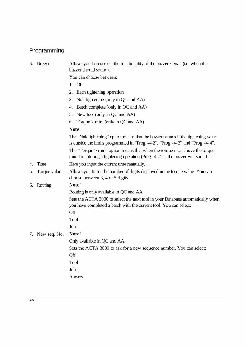
3. Buzzer Allows you to set/select the functionality of the buzzer signal. (i.e. when the buzzer should sound). You can choose between: 1. Off 2. Each tightening operation 3. Nok tightening (only in QC and AA) 4. Batch complete (only in QC and AA) 5. New tool (only in QC and AA) 6. Torque > min. (only in QC and AA) Note! The “Nok tightening” option means that the buzzer sounds if the tightening value is outside the limits programmed in “Prog.-4-2”, “Prog.-4-3” and “Prog.-4-4”. The “Torque > min” option means that when the torque rises above the torque min. limit during a tightening operation (Prog.-4-2-1) the buzzer will sound.
4. Time Here you input the current time manually. 5. Torque value Allows you to set the number of digits displayed in the torque value. You can
choose between 3, 4 or 5 digits. 6. Routing Note!
Routing is only available in QC and AA. Sets the ACTA 3000 to select the next tool in your Database automatically when you have completed a batch with the current tool. You can select: Off Tool Job
7. New seq. No. Note! Only available in QC and AA. Sets the ACTA 3000 to ask for a new sequence number. You can select: Off Tool Job Always
Programming
47
About Routing
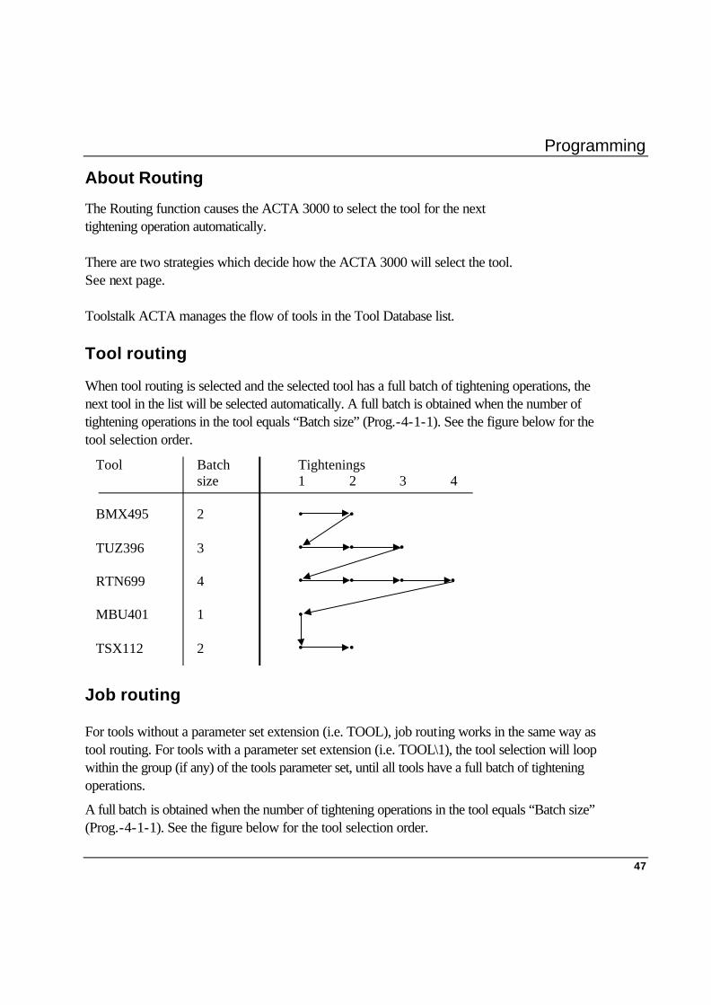
The Routing function causes the ACTA 3000 to select the tool for the next tightening operation automatically. There are two strategies which decide how the ACTA 3000 will select the tool. See next page. Toolstalk ACTA manages the flow of tools in the Tool Database list. Tool routing
When tool routing is selected and the selected tool has a full batch of tightening operations, the next tool in the list will be selected automatically. A full batch is obtained when the number of tightening operations in the tool equals “Batch size” (Prog.-4-1-1). See the figure below for the tool selection order.
Tool Batch Tighteningssize 1 2 3 4
BMX495 2 • •
TUZ396 3 • • •
RTN699 4 • • • •
MBU401 1 •
TSX112 2 • •
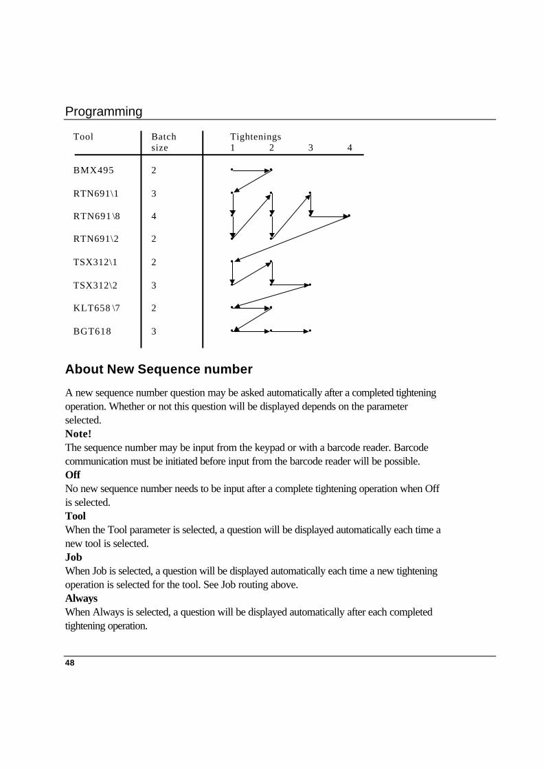
Job routing
For tools without a parameter set extension (i.e. TOOL), job routing works in the same way as tool routing. For tools with a parameter set extension (i.e. TOOL\1), the tool selection will loop within the group (if any) of the tools parameter set, until all tools have a full batch of tightening operations.
A full batch is obtained when the number of tightening operations in the tool equals “Batch size” (Prog.-4-1-1). See the figure below for the tool selection order.
Programming
48
Tool Batch Tighteningssize 1 2 3 4
BMX495 2 • •
RTN691\1 3 • • •
RTN691 \8 4 • • • •
RTN691\2 2 • •
TSX312\1 2 • •
TSX312\2 3 • • •
KLT658 \7 2 • •
BGT618 3 • • •
About New Sequence number
A new sequence number question may be asked automatically after a completed tightening operation. Whether or not this question will be displayed depends on the parameter selected. Note! The sequence number may be input from the keypad or with a barcode reader. Barcode communication must be initiated before input from the barcode reader will be possible. Off No new sequence number needs to be input after a complete tightening operation when Off is selected. Tool When the Tool parameter is selected, a question will be displayed automatically each time a new tool is selected. Job When Job is selected, a question will be displayed automatically each time a new tightening operation is selected for the tool. See Job routing above. Always When Always is selected, a question will be displayed automatically after each completed tightening operation.

Programming
49
8.3.3 Port Interface This is where you set your printer and communication preferences.
Re-open menu block “Conf.” and select 1-3. Port Interface.
A dialog box pops up with a list of the following parameters, each containing a few options to select from or for inputting data manually:
Function Explanation Printer protocol Here you select the protocol that suits your printer.
The ACTA 3000 can communicate with some printers on the market using one of the following protocols: Epson, IBM and PCL3. When purchasing a printer for the ACTA 3000, check that it can handle one of these protocols.
Paper size Here you select the paper format for printing. A4 or Letter.
Colour Here you select colour or black and white printing.
Note!
It is important that the Baud rate and Flow control parameters are configured identically in both ACTA 3000 and ToolsTalk ACTA.
Baud rate Here you select Baud rate for the ACTA 3000 for communication with ToolsTalk ACTA and your barcode reader.
You can select: 9600, 19200, 38400, 57600 or 115200 bps.
Flow control Here you can select your flow control; the “handshake” to be used when communicating with ToolsTalk ACTA.
Choose between Hardware and Xon/Xoff.
Preferred setting is 115200 and Hardware
Barcode position Here you set the start position for the sequence number in the string read by the Barcode reader.
Barcode length Here you set the number of characters to be used from the read Barcode for the sequence number. The sequence number starts in the position set by Barcode position.

Programming
50
Setting Port Interface
With the Port Interface dialog box open…
1. Use the arrows to scroll between (highlight) the 5 different parameters.
2. Select and open a parameter by highlighting it and then pressing ‘Enter’ or by simply pressing the corresponding number for each parameter on the keypad.
3. When you have opened a parameter as described above, a dialog box pops up with options to select from.
4. Select your option within the open parameter by highlighting it and then pressing ‘Enter’ or simply press its corresponding number on the keypad.
Now continue to set all six parameters in Port Interface by repeating steps 1-4.
5. When you have set all parameters to your satisfaction you must confirm your selection and then exit the User Interface dialog box.
6. To do this, use the arrows to highlight the OK sign in the top left corner and press ‘Enter’ or simply press the ‘OK’ button on the keypad.
Your selections are confirmed and the measurement dialog box returns.
If you need to exit the Print Interface dialog box without saving the changes, simply press menu block “Cancel”.
8.3.4 Calibration Re-open menu block “Conf.” (for programming tree, see 7.5 Configuration) and select 2. Calibration. With the ACTA 3000 you can calibrate all your transducers using this parameter. This parameter is also used for calibrating your ACTA 3000. The Calibration menu block is also used for calibrating tools. Refer to special chapter on Calibration for details.
ACTA Reference box calibration. Calibrates the ACTA 3000.
Deadweight Deadweight calibration. Calibrates transducers.
Tool Tool calibration. Calibrates tools and tool controllers.
See Chapter 12, Calibration, for more details.

Programming
51
8.3.5 Diagnostics Re-open menu block “Conf.” (for programming tree, see 7.5 Configuration) and select 3. Diagnostics.
There are information dialog boxes for displaying the charge left in the battery, calibration diagnostics for your ACTA, shunt calibration diagnostics for your transducer and track information on both torque and angle.
Transducer Displays calibration diagnostics for the measuring system (ACTA 3000 and transducer).
Battery Displays information about battery status and whether the mains is connected or not.
Track This dialog box displays torque and angle continuously. The torque will be updated only if it rises above the “Cycle start” torque (Prog.-3-2-1). The angle will be set to zero by pressing the ‘Reset’ key. The ‘Cancel’ key is used to exit from the dialog box.
8.3.6 Transducer memory Re-open menu block “Conf.” (for programming tree, see 7.5 Configuration) and select 4. Transducer memory.
This is an information dialog box displaying the data received from an Atlas Copco memory transducer. Therefore, if you are using one, you will be able to see the serial number, sensitivity, calibration torque, torque span, angle encoder, calibration date and the number of measurements that have been made with that specific transducer.
The transducer memory information is shown in two dialog boxes. To switch between the two dialog boxes use the right and left arrow softkeys.
Information shown:
§ Type of transducer
§ Serial number
§ Sensitivity
§ Calibration torque
§ Torque span
§ Angle encoder
§ Number of measurements (tightening operations)

Programming
52
§ Calibration date
§ Calibration source (ACTA 3000 or other calibration equipment)
§ Next calibration date
§ Last update of calibration torque (date)
§ Signature of calibrator
§ Comments
Note! When an Atlas Copco transducer with memory is connected to the ACTA 3000, a check of the next calibration date is performed:
§ If there are less than 30 days to the next calibration date, a dialog box appears telling the operator that the transducer needs to be calibrated before the next calibration date.
§ If the next calibration date has passed, a dialog box appears telling the operator that the transducer needs to be calibrated.
8.3.7 Product information Re-open menu block “Conf.” (for programming tree, see 7.5 Configuration) and select 5. Product information.
This is an information dialog box displaying the serial number, hardware revision, software revision and calibration date on your ACTA 3000.
Information shown: • ACTA 3000 serial number • Hardware revision • Software revision • ACTA 3000 calibration date. • Next calibration date for the ACTA 3000.
Note!
When the ACTA 3000 is powered up, a check of the next calibration date is performed:
§ If there are less than 30 days to the next calibration date, a dialog box appears telling the operator that the ACTA 3000 needs to be calibrated before the next calibration date.
§ If the next calibration date has passed, a dialog box appears telling the operator that the ACTA 3000 needs to be calibrated.
Programming
53
8.3.8 Options
Using this dialog box, different options can be enabled in the ACTA 3000.
They are not described in this manual.
For further information, please contact your Atlas Copco representative.
8.4 Quick Programming (Q.Prog.)
Available in Basic, Quality Control and Advanced Analysis versions.
For programming instructions, see Chapter 5.
8.5 Calibration (Cal.)
Available in Basic, Quality Control and Advanced Analysis versions. When you Attach a new transducer, or switch on the ACTA 3000, the ACTA 3000 always performs a shunt calibration. However, you may sometimes want to perform an extra calibration, perhaps when the first calibration failed because there was a load on the transducer during calibration. In that case you use the ‘Cal.’ button to perform a new shunt calibration.
If you are not using an Atlas Copco Tools IRTT transducer with memory, read the section below.
8.5.1 Setting up your non-Atlas Copco memory type transducer
By pressing the ‘Cal.’ softkey or connecting a new transducer, a transducer database selection dialog box will be displayed, see the figure below. This dialog box consists of a list of 10 positions. Each position is capable of holding a set of transducer data. The following are displayed for each position:
• Number
• Comment
• Serial number
Programming
54
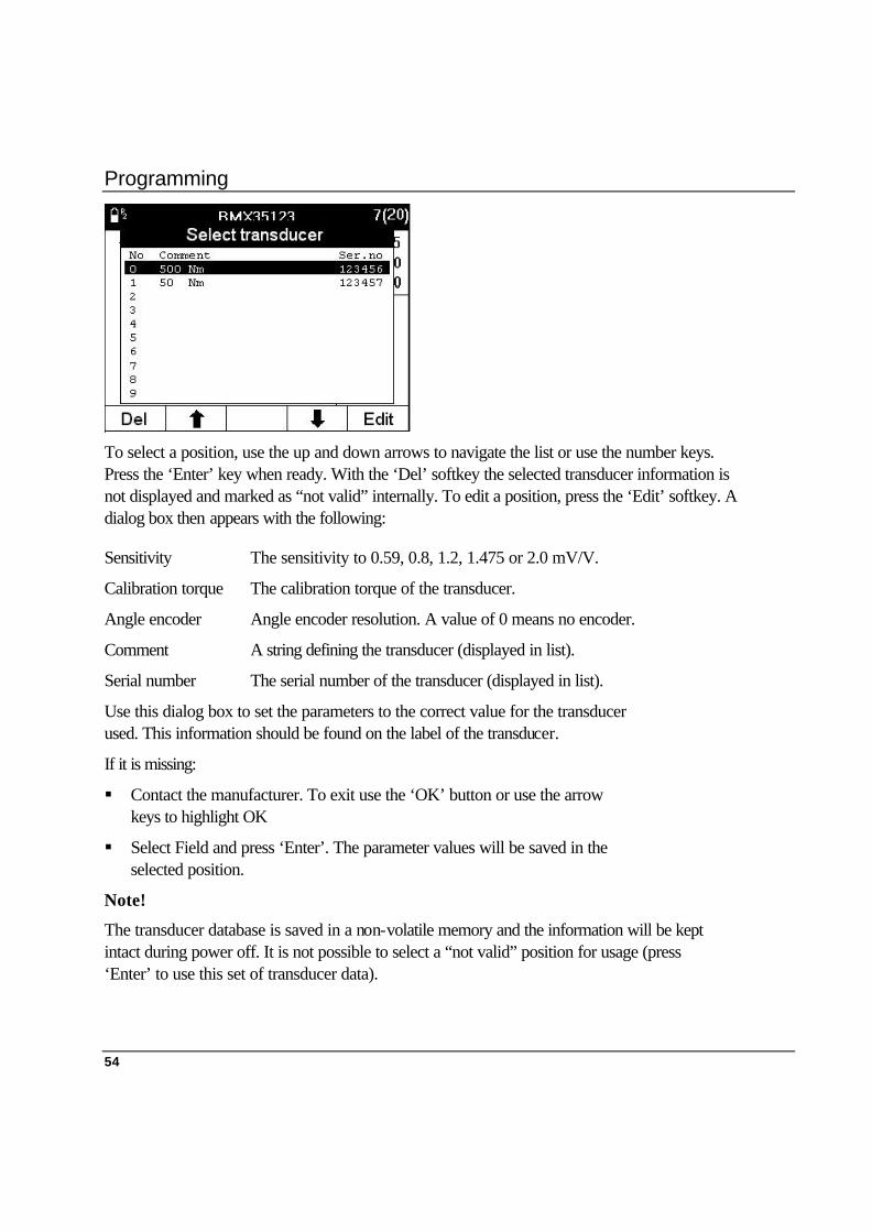
To select a position, use the up and down arrows to navigate the list or use the number keys. Press the ‘Enter’ key when ready. With the ‘Del’ softkey the selected transducer information is not displayed and marked as “not valid” internally. To edit a position, press the ‘Edit’ softkey. A dialog box then appears with the following:
Sensitivity The sensitivity to 0.59, 0.8, 1.2, 1.475 or 2.0 mV/V.
Calibration torque The calibration torque of the transducer.
Angle encoder Angle encoder resolution. A value of 0 means no encoder.
Comment A string defining the transducer (displayed in list).
Serial number The serial number of the transducer (displayed in list).
Use this dialog box to set the parameters to the correct value for the transducer used. This information should be found on the label of the transducer.
If it is missing:
§ Contact the manufacturer. To exit use the ‘OK’ button or use the arrow keys to highlight OK
§ Select Field and press ‘Enter’. The parameter values will be saved in the selected position.
Note!
The transducer database is saved in a non-volatile memory and the information will be kept intact during power off. It is not possible to select a “not valid” position for usage (press ‘Enter’ to use this set of transducer data).

Programming
55
8.6 Database (Datab.) Available in Quality Control and Advanced Analysis. The Quality Control and Advanced Analysis versions feature a tool database where you can create setups to match different tools you measure frequently. It allows you to organise as well as measure data for each tool.
Open the Datab. menu block and a pop-up menu appears with the following options: Datab.
1. New tool
2. Select tool
3. Delete tool----------------
1 Selected tool
2 All tools
4. Clear all measurements
5. Backup tool
6. Information
8.6.1 New Tool
1. Select 1. New Tool (highlight it and press ‘Enter’ or quick-select it on the numeric keypad) and a pop-up dialog box appears with the text “Specify new tool, max. 20 characters”.
2. Use the numeric keypad to enter the ID of the new tool. The ‘Shift’ button gives access to letters.
3. When finished, press ‘Enter’. Another pop-up dialog box flashes with the text “Copying setup to (the new tool’s ID)”.
The ACTA 3000 copies all the settings of the current tool to the new tool you have created and will then automatically select and display the new tool. Note how the tool ID at the top of the screen has changed to the new tool ID. All measurements now made will be linked to the new tool.

Programming
56
8.6.2 Select Tool
Note! It is not possible to measure tightening operations with a backup tool. Refer to Chapter Backup Tool.
1. Open the Datab. menu block again.
2. Choose Select Tool or All Tools.
3. Select 2. Select Tool (highlight it and press ‘Enter’ or quick-select it on the alpha-numeric keypad) and two pop-up dialog boxes appear; a large dialog box that displays all tools you have created and saved in the database, and a small dialog box with the text “Specify tool name”.
4. You can now select the tool you require by selecting your tool with the arrows and pressing ‘Enter’. Note that the arrows allow you to scroll through your tools in the database.
5. If you have a lot of tools in the database you can search for a tool by typing its tool ID in the small “Specify tool name” dialog box. When you enter the tool ID, it will be highlighted in the large dialog box and simply press ‘Enter’ to select it.
When you have completed step 3 or 4, the ACTA 3000 will automatically return to the measurement dialog box. Your tool selection is confirmed by its tool ID which is now displayed at the top of the measurement dialog box.
This will be the tool you measure until you select another tool by repeating the Select Tool operation.
Under this menu block you can also select tools under the Select menu block.
Programming
57
8.6.3 Delete Tool
This function will allow you to delete the selected tool or all tools (including their tightening data) in the database. The delete function affects the current tool selected; i.e. the tool currently displayed. Therefore, to delete a tool, first select the tool and then use this function to delete it.
1. Open the Datab. menu block again.
2. Highlight function 3. Delete Tool and press ‘Enter’. Choose Select Tool or All Tools.
A warning box appears confirming this function and asking “Are you sure?”
3. Check that the tool ID in the measurement dialog box is the tool you want to delete.
§ If it is not the correct tool ID, press ‘Enter’ to exit this dialog box and return to the measurement dialog box.
§ If it is correct, use the arrows to highlight OK and then press ‘Enter’ or press the ‘OK’ button on the keypad. A pop-up dialog box flashes confirming the deleting process.
The tool that was displayed has now been deleted along with all its tightening data and you return automatically to the measurement dialog box. The measurement dialog box now displays the saved tool in your database immediately before the one that you just deleted. Note!
It is not possible to delete the default tool, tool number 1, in your database.

Programming
58
8.6.4 Clear all measurements
This function allows you to delete all measurement data for all your tools in the database. Note that it will not delete but update your historic statistical measurement data under the “Hist.” menu block.
1. Open the Datab. menu block again.
2. Highlight function 4. Clear all measurements and press ‘Enter’. A warning text appears confirming this function and asking “Are you sure?”
3. If you are not sure, press ‘Enter’ in order to exit this dialog box and return to the measurement dialog box.
4. If you are sure, use the arrows to highlight OK and then press ‘Enter’ or press the ‘OK’ button on the keypad. A pop-up dialog box flashes to confirm deletion.
Note! All tool measurement data for all your tools has been deleted and the measurement dialog box returns.
8.6.5 Backup tool
This function allows you to create a copy of the selected tool, including all the tightening operations and history data. This function is used when you have noticed, for example that a tool needs to be calibrated and you want to save your “bad” tightening operations for history data.
A warning text appears confirming this function and asks “Are you sure?” The backup tool will be given its normal name and the extension “[#]”.
For example:
BMX123 ------> BMX123[0] (first backup).
BMX123 ------> BMX123[1] (second backup).
Note!
• Number 0 is for the first backup, 1 for next and so on.
• It is not possible to measure with a backup tool.
• It is not possible to create a new tool from a backup tool.
• It is not possible to make a backup of a backup tool.
• After a backup, all tightening in the original tool are removed.

Programming
59
8.7 Select Tool (Select) Available in Quality Control and Advanced Analysis versions.
This function is used to select different tools in your database.
1. Open the Select menu block and two pop-up dialog boxes appear. One large dialog box that displays all the tools you have created and saved in the database and a small dialog box with the text “Specify tool name”.
2. You can now select the tool you require by selecting your tool with the arrows and pressing ‘Enter’. Note that the arrows allow you to scroll through your tools in the database.
3. If you have a lot of tools in the database you can search for a tool by typing its tool ID in the small dialog box “Specify tool name”. When you enter the tool ID, it will be highlighted in the large dialog box and simply press ‘Enter’ to select it.
When you have completed step 2 or 3, the ACTA 3000 will automatically return to the measurement dialog box. Your tool selection is confirmed by its tool ID which is now displayed at the top of the measurement dialog box.
Note!
This will be the tool you measure until you select another tool by repeating steps 1 and 2.
Programming
60
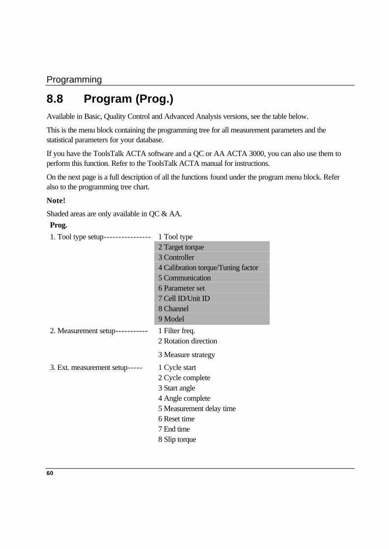
8.8 Program (Prog.) Available in Basic, Quality Control and Advanced Analysis versions, see the table below.
This is the menu block containing the programming tree for all measurement parameters and the statistical parameters for your database.
If you have the ToolsTalk ACTA software and a QC or AA ACTA 3000, you can also use them to perform this function. Refer to the ToolsTalk ACTA manual for instructions.
On the next page is a full description of all the functions found under the program menu block. Refer also to the programming tree chart.
Note!
Shaded areas are only available in QC & AA. Prog. 1. Tool type setup---------------- 1 Tool type 2 Target torque 3 Controller 4 Calibration torque/Tuning factor 5 Communication 6 Parameter set 7 Cell ID/Unit ID 8 Channel 9 Model 2. Measurement setup----------- 1 Filter freq. 2 Rotation direction
3 Measure strategy
3. Ext. measurement setup----- 1 Cycle start 2 Cycle complete 3 Start angle 4 Angle complete 5 Measurement delay time 6 Reset time 7 End time 8 Slip torque
Programming
61
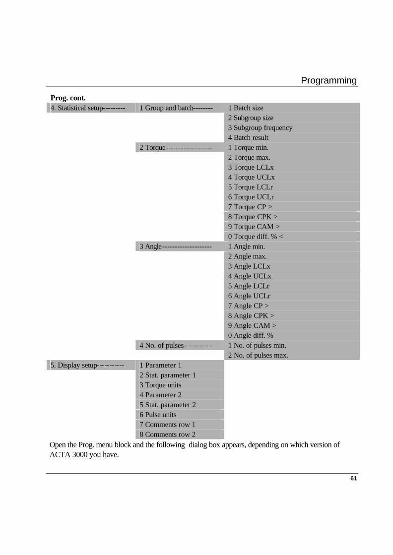
Prog. cont. 4. Statistical setup--------- 1 Group and batch-------- 1 Batch size 2 Subgroup size 3 Subgroup frequency 4 Batch result 2 Torque------------------- 1 Torque min. 2 Torque max. 3 Torque LCLx 4 Torque UCLx 5 Torque LCLr 6 Torque UCLr 7 Torque CP > 8 Torque CPK > 9 Torque CAM > 0 Torque diff. % < 3 Angle-------------------- 1 Angle min. 2 Angle max. 3 Angle LCLx 4 Angle UCLx 5 Angle LCLr 6 Angle UCLr 7 Angle CP > 8 Angle CPK > 9 Angle CAM >
0 Angle diff. % 4 No. of pulses------------ 1 No. of pulses min. 2 No. of pulses max. 5. Display setup----------- 1 Parameter 1 2 Stat. parameter 1 3 Torque units 4 Parameter 2 5 Stat. parameter 2 6 Pulse units 7 Comments row 1 8 Comments row 2 Open the Prog. menu block and the following dialog box appears, depending on which version of ACTA 3000 you have.
Programming
62
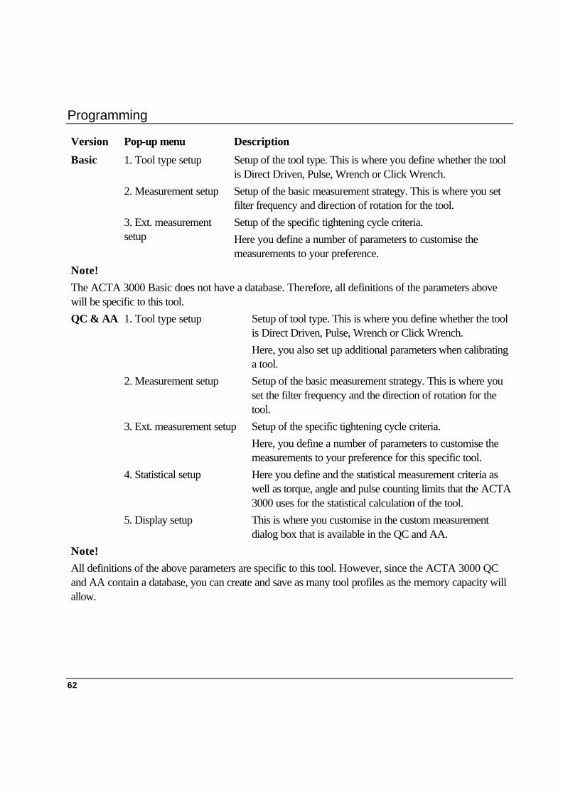
Version Pop-up menu Description
Basic 1. Tool type setup Setup of the tool type. This is where you define whether the tool is Direct Driven, Pulse, Wrench or Click Wrench.
2. Measurement setup Setup of the basic measurement strategy. This is where you set filter frequency and direction of rotation for the tool.
3. Ext. measurement setup
Setup of the specific tightening cycle criteria. Here you define a number of parameters to customise the measurements to your preference.
Note! The ACTA 3000 Basic does not have a database. Therefore, all definitions of the parameters above will be specific to this tool. QC & AA 1. Tool type setup Setup of tool type. This is where you define whether the tool
is Direct Driven, Pulse, Wrench or Click Wrench. Here, you also set up additional parameters when calibrating a tool.
2. Measurement setup Setup of the basic measurement strategy. This is where you set the filter frequency and the direction of rotation for the tool.
3. Ext. measurement setup Setup of the specific tightening cycle criteria. Here, you define a number of parameters to customise the measurements to your preference for this specific tool.
4. Statistical setup Here you define and the statistical measurement criteria as well as torque, angle and pulse counting limits that the ACTA 3000 uses for the statistical calculation of the tool.
5. Display setup This is where you customise in the custom measurement dialog box that is available in the QC and AA.
Note! All definitions of the above parameters are specific to this tool. However, since the ACTA 3000 QC and AA contain a database, you can create and save as many tool profiles as the memory capacity will allow.

Programming
63
8.8.1 Tool type setup
Basic
When selecting the “Tool type” setup a pop-up dialog box appears with one parameter:
1 Tool type You can choose between Direct Driven, Pulse,
Wrench and Click Wrench.
1. Use the arrows to highlight (select) the above parameters. Open each of the parameters by pressing ‘Enter’.
2. Select your preference in each parameter by highlighting one alternative and then pressing ‘Enter’, or by pressing its corresponding number on the keypad.
3. When the selection is made, highlight OK and press ‘Enter’, or simply press the ‘OK’ button on the keypad. Tool type setup is now complete and saved and the pop-up dialog box disappears.
QC & AA
When selecting the “Tool type” setup a pop-up dialog box appears with a number of parameters. The “Controller” parameter defines the number of parameters visible on the display.
1. Tool type You can choose between Direct Driven, Pulse, Wrench and Click
Wrench.
2. Target torque Used in “None” or “DS” tool calibration and corresponds to the target torque setting in the manual non-controlled tool (None) or the DS controlled tool (DS).
Programming
64
3. Controller Used in tool calibration to select the type of controller to calibrate. There are 6 types:
1. None
2. Other controller
3. F2000/PF2000
4. DS
5. PF3000
6. Power Macs
• “None” is used for handheld or non-controlled tools.
• ”Other controller” is used for unknown or unsupported controlled tools. Manual input of controller tightening values is required.
• “F2000/PF2000” is used for Focus 2000 and Power Focus 2000 controlled tools. If selected, controller tightening values are automatically received from the controller after each tightening operation.
• “DS” is used for DS controlled tools. If selected, no tightening values are read from the controller after each tightening.
• “PF3000” is used for Power Focus 3000 controlled tools. If selected, controller tightening values are automatically received from the controller after each tightening. No tightening values are read from controller for “PF3000” model “Tensor DS”.
• “PowerMacs” is used for PowerMac controlled tools. If selected, controller tightening values are automatically received from the controller after each tightening operation.
4. Calibration torque Used in “Other controller”, “F2000/PF2000”, “PF3000” or “PowerMac” tool calibration and corresponds to the calibration torque in the unknown or unsupported controlled tools (Other controller) or the F2000/PF2000 controller (F2000/PF2000), PF3000 controller (PF3000) or PowerMac controller (PowerMac).
Programming
65
5. Tuning factor Used in “DS” tool for the torque tuning factor. Also used in “PF3000” with tool model “Tensor DS”.
6. Communication Used in tool calibration to select the type of communication that is to be used. For each type of controller, “Manual input” or “RS232” can be selected. For DS controller and PF3000, ”Infrared” can also be selected. When selecting “Manual input”, the user is asked for controller torque and controller angle in input fields after each tightening operation. When “RS232” or “Infrared” is selected, controller tightening values are automatically read from the controller after each tightening operation.
7. Parameter set Used in “F2000/PF2000”, “PF3000” and “DS” tool calibration for selecting the parameter set to be used when calibrating.
8. Cell ID/Unit ID Used in PF3000 tool calibration to select cell and in Focus2000/PF2000 to select unit ID.
9. Channel Used in Focus2000/PF2000 and PF3000 tool calibration to select channel.
10. Model Used in PF3000 tool calibration to select tool model. You can choose between Tensor S or Tensor DS.

Programming
66
8.8.2 Measurement setup
1. Open the “Prog.” menu block, select 2. Measurement setup and a pop-up dialog box with three parameters appears:
1. Filter Frequency Filter frequency is the frequency used for filtering out noise from the transducer signals. You input a numeric (Hz) value manually.
2. Rotation Direction You can choose between Clockwise (CW), Anticlockwise (ACW) or both.
3. Measure strategy Select measure strategy. Only visible for wrench type tools . You can choose between Peak torque or Static installed torque.
2. Use the arrows to highlight (select) the above parameters. Open each of the parameters by pressing ‘Enter’.
3. Select your preference in each parameter by highlighting one alternative and then pressing ‘Enter’ or by pressing its corresponding number on the keypad.
4. Filter frequency is input manually using the digits on the keypad. Press ‘Enter’ to confirm.
5. When all selections have been made, highlight OK and press ‘Enter’ or simply press the ‘OK’ button on the keypad. Measurement Setup is now complete and saved and the pop-up dialog box disappears.
If you need to exit Measurement Setup prematurely before setting your preferences, highlight Cancel and then press ‘Enter’ or simply press the menu block showing Cancel. None of the selected preferences will take effect.

Programming
67
8.8.3 Extended Measurement Setup 1. Open the “Prog.” menu block, select 3.
Ext. measurement Setup and a pop-up dialog box with eight parameters appears:
1. Cycle start The torque level at which the tightening cycle begins. Input numeric torque value manually.
2. Cycle complete The torque level at which the tightening cycle ends. Input numeric torque value manually.
3. Start angle The torque level at which the angle measurement begins. Input numeric torque value manually.
4. Angle complete Selects Angle complete measurement criteria. Choose from the following:
1. Peak torque
2. Peak angle
3. Cycle complete
• “Peak torque” means that the angle is measured between “Angle start” and the measured peak (max.) torque in the tightening operation.
• “Peak angle” means that the angle is measured between ”Angle start” and the peak (max.) angle in the tightening operation.
• “Cycle complete” means that the angle is measured between “Angle start” and “Cycle complete” in the tightening operation.
5. Measure delay time A delay occurs after cycle start is reached before the actual measurement starts. This is because of the peaks which can occur during rundown, before the actual tightening operation starts. Input numeric (ms) value manually.
6. Reset time The time after cycle complete when the ACTA 3000 is ”blind”. This is used to filter out peaks which occur after tightening and do not affect the tightening result. Input numeric (ms) value.
7. End time The time the ACTA 3000 must wait after the Cycle Complete level, before the tightening cycle is considered complete. This delay time is necessary for the two-stage strategy. Input numeric (ms) value manually.
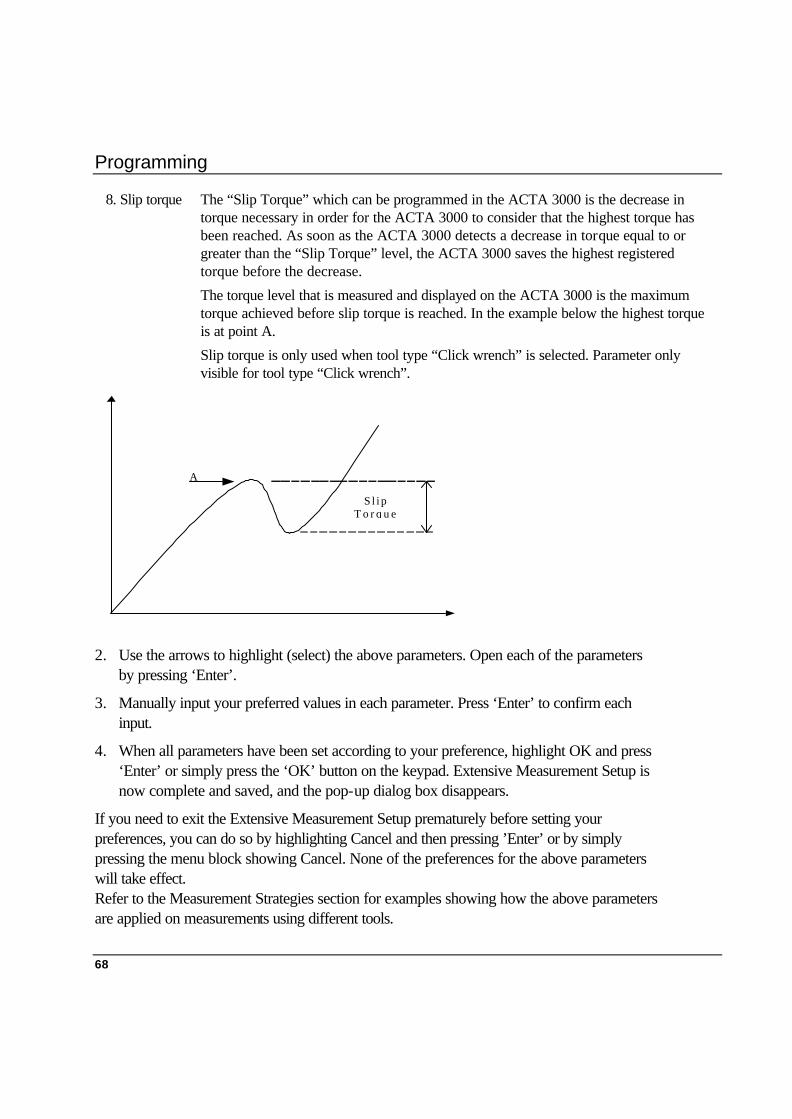
Programming
68
8. Slip torque The “Slip Torque” which can be programmed in the ACTA 3000 is the decrease in torque necessary in order for the ACTA 3000 to consider that the highest torque has been reached. As soon as the ACTA 3000 detects a decrease in torque equal to or greater than the “Slip Torque” level, the ACTA 3000 saves the highest registered torque before the decrease.
The torque level that is measured and displayed on the ACTA 3000 is the maximum torque achieved before slip torque is reached. In the example below the highest torque is at point A.
Slip torque is only used when tool type “Click wrench” is selected. Parameter only visible for tool type “Click wrench”.
2. Use the arrows to highlight (select) the above parameters. Open each of the parameters by pressing ‘Enter’.
3. Manually input your preferred values in each parameter. Press ‘Enter’ to confirm each input.
4. When all parameters have been set according to your preference, highlight OK and press ‘Enter’ or simply press the ‘OK’ button on the keypad. Extensive Measurement Setup is now complete and saved, and the pop-up dialog box disappears.
If you need to exit the Extensive Measurement Setup prematurely before setting your preferences, you can do so by highlighting Cancel and then pressing ’Enter’ or by simply pressing the menu block showing Cancel. None of the preferences for the above parameters will take effect. Refer to the Measurement Strategies section for examples showing how the above parameters are applied on measurements using different tools.
A
S l i pT o r q u e

Programming
69
8.8.4 Statistical setup
Open the Prog. menu block and select 4. Ext. Measurement Setup and a second pop-up dialog box appears with the following options:
• Group and Batch
• Torque
• Angle
• Pulse
Setting Group and Batch
1. Open 1. Group and Batch and a pop-up dialog box with four parameters appears:
1. Batch Size This is where you define the batch size to be used when performing measurements with the ACTA 3000. Batch size is the number of tightening operations you decide need to be made for a full performance test of the tool
2. Subgroup Size This is where you define the size of the subgroup used for the SPC (statistic process control) calculations. For more information on SPC, read the chapter on statistics
3. Subgroup Frequency
Here is where you define the frequency with which the subgroups are taken from the population of tightening operations saved in the ACTA 3000.
“1” means that you use all tightening operations for your SPC analysis. “2” means that you use every second subgroup for your SPC analysis. “3” mean that you use every third subgroup for your SPC analysis.
Example: “Subgroup size” = 5 and “Subgroup frequency” = 3. The ACTA 3000 will then use the first 5 tightening operations, then skip 10 tightening operations, use the next 5 tightening operations, skip 10 and so on.
4. Batch Result After the first completed batch, you can instruct the ACTA 3000 to display the batch result before the next batch can be initiated. The batch result tells you whether the batch is OK or if any torque and/or angle value is outside the specified limits.
Programming
70
4. Manually input your preferred values in each parameter. Press ’Enter’ to confirm each input. With Batch Result, select On or Off.
5. When all parameters have been set according to your preference, highlight OK and press ‘Enter’ or simply press the ‘OK’ button on the keypad. Group and Batch Setup is now complete and saved and the pop-up dialog box disappears.
If you need to exit the Group and Batch setup prematurely before setting your preferences, you can do so by highlighting Cancel and then pressing ‘Enter’ or by simply pressing the menu block showing Cancel. None of the preferences for the above parameters will take effect.
Setting Torque (setup)
1. Re-open the Prog. menu block, select 4. Statistical setup.
2. Open 2. Torque and a pop-up dialog box with ten parameters appears:
1. Torque min. This is where you define the minimum torque limit for each measurement.
2. Torque max. This is where you define the maximum torque limit for each measurement.
3. Torque LCLx This is where you define the lower control limit for each subgroup x-bar value. See the Statistics chapter for more information.
4. Torque UCLx This is where you define the upper control limit for each subgroup x-bar value. See the Statistics chapter for more information.
5. Torque LCLr This is where you define the lower control limit for each subgroup range values. See the Statistics chapter for more information.
6. Torque UCLr This is where you define the upper control limit for each subgroup range value. See the Statistics chapter for more information.
7. Torque CP > This is where you define the minimum allowed CP value. Values below this minimum value will initiate statistical alarms. See the Statistics chapter for more information.
8. Torque CPK > This is where you define the minimum allowed CPK value. Values below this minimum value will initiate statistical alarms. See the Statistics chapter for more information.
Programming
71
9. Torque CAM > This is where you define the minimum allowed CAM value. Values below this minimum value will initiate statistical alarms. See the Statistics chapter for more information.
10. Torque diff. % < This is where you define the maximum allowed mean difference in per cent between torque and controller torque. See the statistics chapter for more information.
3. Use the arrows to highlight (select) the above parameters. You open each parameter by pressing ‘Enter’.
4. Manually input your preferred values in each parameter. All inputs are numerical torque values. Press ‘Enter’ to confirm each input.
5. When all parameters have been set according to your preference, highlight OK and press ‘Enter’ or simply press the ‘OK’ button on the keypad. Torque setup is now complete and saved and the pop-up dialog box disappears.
If you need to exit the Torque setup prematurely before setting your preferences highlight Cancel and press ‘Enter’ or simply press the menu block showing Cancel. None of the preferences for the above parameters will take effect.

Programming
72
Setting Angle (setup)
1. Re-open the Prog. menu block, select 4. Statistical setup.
2. Open 3. Angle and a pop-up dialog box with ten parameters appears:
1. Angle min. Used to define the minimum angle limit for each measurement.
2. Angle max. Used to define the maximum angle limit for each measurement.
3. Angle LCLx Used to define the lower control limit for each subgroup x-bar value. Refer to the Statistics chapter for more information.
4. Angle UCLx Used to define the upper control limit for each subgroup x-bar value. Refer to the Statistics chapter for more information.
6. Angle UCLr Used to define the upper control limit for each subgroup range values. Refer to the Statistics chapter for more information.
7. Angle CP > Used to define the minimum allowed CP value. Values below this minimum value will initiate statistical alarms. Refer to the Statistics chapter for more information
8. Angle CPK > Used to define the minimum allowed CPK value. Values below this minimum value will initiate statistical alarms. Refer to Statistics chapter for more information.
9. Angle CAM > Used to define the minimum allowed CAM value. Values below this minimum value will initiate statistical alarms. Refer to the Statistics chapter for more information.
10. Angle diff % < Used to define the maximum allowed mean difference in per cent between torque and controller torque. Refer to the Statistics chapter for more information.
3. Use the arrows to highlight (select) the above parameters. Open each parameter by pressing ‘Enter’.
4. Manually input your preferred values in each parameter. All inputs are numerical angle (degrees) values. Press ‘Enter’ to confirm each input.

Programming
73
5. When all parameters have been set according to your preference, highlight OK and press ‘Enter’ or simply press the ‘OK’ button on the keypad. Angle setup is now complete and saved and the pop-up dialog box disappears.
If you need to exit the Angle setup prematurely before setting your preferences, highlight Cancel and then press ‘Enter’ or simply press the menu block showing Cancel. None of the preferences for the above parameters will then take effect.
Setting Pulse (setup)
1. Re-open the Prog. menu block, select 4. Statistical setup.
2. Open 4. Pulse and a pop-up dialog box with two parameters appears:
1. No. of pulses, min. Sets the minimum number of pulses for the measurement
2. No. of pulses, max. Sets the maximum number of pulses for the measurement.
3. Use the arrows to highlight (select) the above parameters. Open each parameter by pressing ‘Enter’.
4. Manually input your preferred values in each parameter. All inputs are numerical values. Press ‘Enter’ to confirm each input.
5. When all parameters have been set according to your preference, highlight OK and press ’Enter’ or simply press the ‘OK’ button on the keypad. Pulse setup is now complete and saved and the pop-up dialog box disappears.
If you need to exit the Pulse setup prematurely before setting your preferences, highlight Cancel and then press ‘Enter’ or simply press the menu block showing Cancel. None of the preferences for the above parameters will then take effect.

Programming
74
8.8.5 Display setup
The ACTA 3000, QC or AA, has a custom measurement display dialog box which is selected from the View menu block (See menu block for more information).
This measurement dialog box can be customised according to your preferences and you select your preferences. under Display setup.
Note!
The custom measurement display of the ACTA 3000 QC and AA is specific to each tool. For each tool it is possible to choose to view details for each specific tool.
Open the Prog. menu block and select (open) 5. Display setup. A pop-up dialog box appears with six different parameters. The following parameters can be customised:
1. Parameter 1
2. Statistical Parameter 1
3. Torque units
4. Parameter 2
5. Statistical Parameter 2
6. Pulse units
7. Comments row 1
8. Comments row 2
Note!
If only one parameter is selected, two pairs of statistical parameters can be selected for that parameter in the Custom measurement display. For example:
• Parameter 1 = Torque
• Parameter 2 = None
• Statistical parameter 1 = X, σ
• Statistical parameter 2 = Min., Max. This setup will display the statistical parameters X, σ, min. and max. for torque in the Custom measurement display.
Programming
75
8.8.6 Parameter 1
This parameter is shown in the top left of the ACTA 3000 custom measurement display. When this parameter is opened a pop-up dialog box appears for you to select one of the following options: 1. Torque (Torque) will display the torque value 2. Angle (Angle) will display the angle value
3. No. of pulses (No. of Pulses) will display the number of pulses
4. C. torque Will display the controller torque value.
5. C. angle Will display the controller angle value.
Statistical Parameter 1
This parameter is displayed in the top right of the ACTA 3000 custom measurement display. This parameter displays real-time statistical calculations on your selection in Parameter 1.
When this parameter is opened a pop-up dialog box appears and one of the following options can be selected: 1. X, σ Mean and sigma for parameter 1.
2. R, None Range for parameter 1.
3. X-3σ, X+3σ, Negative and positive confidence interval for parameter 1.
4. Min., Max. Min. and max. values for parameter 1.
5. Var., Diff. % Variance and difference in percent between parameter 1 and the controller value for parameter 1. “Diff. %” is only valid and displayed when parameter 1 is torque, angle, controller torque or controller angle.
6. CP, CPK CP and CPK for parameter 1.
7. X last, R last Last group X-bar and last group range for parameter 1. Displayed only when there is at least one full group.
8. CAM, None CAM for parameter 1. Displayed only when there are at least 6 full groups.
9. Contr., Diff. Controller value and difference between parameter 1 and the controller value for parameter 1. “Contr.” and “Diff.” is only valid and displayed when parameter 1 is torque, angle, controller torque or controller angle.
0. None, None No statistical parameters are selected.
Programming
76
Torque units
Sets the units used for the torque in this tool.
1. Nm
2. ozf.in
3. lbf.in
4. lbf.ft
5. kgt.m
6. kgf.cm
Parameter 2
This parameter is displayed on the left of the ACTA 3000 custom measurement display, below Parameter 1. When this parameter is opened a pop-up dialog box appears for you to select one of the following options:
1. Torque (Torque) will display the torque value
2. Angle (Angle) will display the angle value
3. No. of pulses (No. of Pulses) will display the number of pulses
4. C. torque Will display the controller torque value.
5. C. angle Will display the controller angle value.
Programming
77
Statistical Parameter 2
This parameter is displayed on the right of the ACTA 3000 custom measurement display, below the statistical field for parameter 1. This parameter displays real-time statistical calculations based on your selection in Parameter 2.
When this parameter is opened a pop-up dialog box appears and one of the following options can be selected: 1. X, σ Mean and sigma for parameter 2.
2. R, None Range for parameter 2.
3. X-3σ, X+3σ, Negative and positive confidence interval for parameter 2.
4. Min., Max. Min. and Max. values for parameter 2.
5. Var., Diff. % Variance and difference in percent between parameter 2 and the controller value for parameter 2. “Diff %” is only valid and displayed when parameter 2 is torque, angle, controller torque or controller angle.
6. CP, CPK CP and CPK for parameter 2.
7. X last, R last Last group X-bar and last group range for parameter 2. Displayed only when at least a full group exists.
8. CAM, None CAM for parameter 2. Displayed only when there are at least 6 full groups.
9. Contr., Diff. Controller value and difference between parameter 2 and the controller value for parameter 2. “Contr.” and “Diff.” are only valid and displayed when parameter 2 is torque, angle, controller torque or controller angle.
0. None, None No statistical parameters are selected.
Programming
78
Pulse units
Sets the units used for the pulse in this tool. 1. Number of 2. Hz
Comments, rows 5 & 6
In the lower part of the ACTA 3000 custom display dialog box there are two rows for comments. These two rows are configured separately. You can enter your own free text of a maximum of 20 characters for each row, or choose from pre-defined options in ToolsTalk ACTA. Refer to the ToolsTalk ACTA manual for detailed information.
Comments row 1 You can enter your own free text or see ToolsTalk ACTA.
Comments row 2 You can enter your own free text or see ToolsTalk ACTA.
Setting the Display Setup
1. Open the “Prog.” menu block and select (open) 5. Display setup.
2. Use the arrows to highlight (select) the above parameters. Open each parameter by pressing ‘Enter’.
3. Select your option under parameters 1-4 or manually input your text using the key in parameters 5-6. Press ‘Enter’ to confirm each input.
4. When all parameters have been set according to your preference, highlight OK and press ‘Enter’ or simply press the ‘OK’ button on the keypad.
Display setup is now complete and saved. The Display setup pop-up dialog box disappears and the measurement dialog box returns.
If you need to exit Display setup prematurely before setting your preferences, highlight Cancel and then press ‘Enter’ or simply press the menu block showing Cancel. None of the preferences for the above parameters will then take effect.

Programming
79
8.9 Speed (Speed) Available in Basic, Quality Control and Advanced Analysis versions. If you are using a transducer that features an angle encoder you can measure the peak and track speed of your tools, both free speed and during a tightening operation.
1. Open the Speed menu block and a pop-up dialog box appears.
2. (Run your tool.)
3. The top figure is your peak speed and below it you can see your track speed. Note the difference in track speed during a tightening operation.
8.10 User (User) Available in Quality Control and Advanced Analysis versions.
When performing measurements, an alpha-numeric code can be added (maximum four characters) to represent the user who is making the measurements.
The user code is saved in the database for all tools that are tested, until a new one is specified. The user code is displayed when the ACTA 3000 is in Custom dialog box mode.
1. Open the User menu block and a pop-up dialog box appears.
2. Enter your code using the alpha-numeric keypad and then press ‘Enter’.
3. You can now see the user name in the bottom left corner of the display in Custom dialog box mode.
To change the user name, repeat the above operation. If you wish to delete the user code, open the User menu block and simply press ‘Enter’.
Programming
80
8.11 Sequence number (Seq. No.) Available in QC and AA.
When performing a measurement session, a sequence number can be added to each tightening operation saved in the database.
The sequence number is saved in the database. The sequence number is displayed when the ACTA 3000 is in Custom dialog box mode. Note! Sequence number zero is not displayed. 1. Open the sequence number menu block and a pop-up dialog box appears. 2. Enter your sequence number code and then press ‘Enter’. 3. The sequence number is now visible in the bottom left corner of the display in
Custom dialog box mode. To change the sequence number, repeat the above operation.
8.12 View (View) Available in Quality Control and Advanced Analysis versions.
There are three different measurement display dialog boxes as described in Chapter 7. The view function allows you to switch between the different measurement display dialog boxes that are available in your version of the ACTA 3000.
Note!
The Setup menu block changes to match the functionality of the measurement display dialog box.
1. Open the View menu block and a pop-up dialog box appears with the following three options: • Basic For menu block combinations, see Chapter 7.3 Measurement
Dialog box / Menu Block Setup Combinations • Custom • Trace
2. Select your desired measurement display dialog box setting by using the arrows to highlight it. Then press ‘Enter’.
3. You can also quick-select your desired dialog box by pressing the corresponding key on the numeric keypad.
The measurement dialog box will be displayed until you repeat the operation above and select another measurement dialog box.
Programming
81
8.13 Manual input (Man.In)
Available in Quality Control and Advanced Analysis modes.
This function allows you to input manual measurement values, including Torque, Angle and Pulses, in to your ACTA 3000.
This is useful where it may be difficult to access an application on the line with a transducer connected to an ACTA 3000. Therefore, you can record the measurements with a digital torque wrench and then enter them manually into the ACTA 3000.
The measurements will be regarded as genuine measurements by your ACTA 3000 but in ToolsTalk ACTA it will be noted that the measurements are manually entered.
1. Select the “Man.In” menu block. A pop up dialog box appears with two parameters:
• Tightening “Tightening” will display the old pop-up dialog box for you to enter tightening values (torque, angle and number of pulses).
• Tool comment “Tool comment” will open an input field for you to enter a comment concerning a tool. For example, if the tool is moved from position or damaged etc.
• Controller Controller” will display a pop-up dialog box for you to enter controller torque and controller angle for the latest tightening operation. The old controller value is displayed in the input field.
2. Select the parameter in which you wish to enter a value, either by highlighting and pressing ‘Enter’ or quick-selecting by number.
3. Input your values by repeating this step.
4. When you have set all parameters to your preference, you must confirm your selection and then exit the Manual Input dialog box.
5. In order to do this, use the arrows to highlight OK in the top left corner and press ‘Enter’ or simply press the ‘OK’ button on the keypad.
Your selections are confirmed; the measurement dialog box returns and you can see your manually entered value on the display.

Programming
82
8.14 Communication (Com.)
Communication selector.
Available in Quality Control and Advanced Analysis versions.
Com. consists of a pop-up menu with the following 3 selections:
1. Controller “Controller” selects communication with the selected controller under certain criteria, see the table below. In other cases ToolsTalk ACTA is selected.
2. ToolsTalk ACTA
“ToolsTalk ACTA” selects communication with the ToolsTalk ACTA PC program.
3. Barcode “Barcode” selects communication with the Barcode Reader.
The type of communication currently active is shown by the communication symbol which is located in the header of the measurement dialog box, see the table below:
Symbol Controller Type of communication
None Serial communication with ToolsTalk ACTA.
Other controller Serial communication with ToolsTalk ACTA.
Focus 2000/PF2000 serial
Focus 2000 / Power Focus 2000 communication selected.
DS serial Serial communication with DS controller if: “Controller” (Prog.-1-5) is set to “DS” “Communication” (Prog.-1-6) is set to “RS232” “Com.” is set to “Controller”.
DS infrared Infrared communication with DS controller if: “Controller” (Prog.-1-5) is set to “DS” “Communication” (Prog.-1-6) is set to “Infrared” “Com.” is set to “Controller”. Note! The operator must aim the ACTA 3000 (the connector side where the IR device is located) at the display of the DS to make communication possible. The operator must press any button on the DS controller after the text on the display flashes. The button should be pressed for a minimum of 2 seconds.

Programming
83
PF3000 serial Power Focus 3000 serial communication selected.
PF3000 infrared Power Focus 3000 infrared communication selected.
Infrared communication with PF controller if:
“Controller” (Prog.-1-3) is set to “PF3000” “Communication” (Prog.-1-5) is set to “Infrared” “Com.” is set to “Controller”.
Barcode serial Barcode communication selected.
PowerMac serial PowerMac communication selected.
If controller is selected and the ACTA 3000 is programmed for infrared, the ACTA 3000 will try to communicate with the controller. Make sure that it is possible to point the ACTA 3000 towards the controller display (infrared). When starting communication on different controllers, the following occurs:
DS infrared:
DS drive will start to flash “- -“, “ -- “. Press the ‘Enter’ button (the arrow) until the display starts flashing “ir”.
PF3000 Compact infrared:
PF drive will start to flash “-Ir-“, “ “. Press ‘Enter’ button (the arrow) until the display starts flashing “-Ir-“, “ Ir “.
PF3000 Graph infrared:
A text window on the screen says:
“IR connect requested from the ACTA 3000 on local channel 0. Press ‘OK’ to acknowledge, wait or cancel to refuse.”
Press ‘OK’ on the PF. A new message appears:
“IR connect requested from the ACTA 3000 on local channel 0. Press ‘OK’ to acknowledge, wait or cancel to refuse.”
This information will be on the display until communication is closed with the “Com” button or another tool is selected on the ACTA 3000.
Programming
84
8.15 Parameters (Param.)
Available in Advanced Analysis versions. Set your ACTA 3000 AA to trace measurement dialog box mode. This function will allow you to select between four different trace modes:
1. Torque(angle) Torque over angle
2. Torque(time) Torque over time
3. Angle(time) Angle over time
4. Torque, angle(time) Torque and angle over time
1. Open the Param. menu block and a pop-up dialog box appears with the above options.
2. Select graph mode by highlighting your selection using the arrows and then pressing ‘Enter’. You can also select graph mode by simply pressing the number corresponding to each graph mode on the keypad.
Your selection is made and the ACTA 3000 uses the new graph mode as a standard until the operation above is repeated and another graph mode is selected.
Programming
85
8.16 Analyse (A.lyse) Available in Advanced Analysis versions.
Set your ACTA 3000 AA to trace measurement dialog box mode. This function allows you to zoom in on sections of your measurement curves for closer study. You can zoom in on a specific area on the trace up to five consecutive times.
The torque can be adjusted by changing the torque arrow position here.
The current trace can be saved in the ACTA 3000 database here.
Open the Analyse menu block and a pop-up menu appears listing the following options:
1. Zoom in
2. Zoom out
3. Adjust position
4. Save trace
8.16.1 To Zoom in
1. Select “Zoom in” by highlighting it using the arrows and then pressing ‘Enter’. Or, you can select it simply by pressing the number corresponding to each graph mode on the keypad.
2. A rectangle appears on the display and four arrows, up, down, left and right, appear in your menu block area.
3. Use the arrows to position the rectangle on a specific area of the measurement curve you wish to zoom in on. Then press ‘Enter’. The area representing the rectangle now represents approximately the full display and the increments on the Y and X axis change accordingly.
To zoom in further, open the Analyse menu block again and repeat steps 1-3. Once again, you can zoom in on a selected area five times.
8.16.2 To Zoom out
1. Open the Analyse menu block again.
2. Select “Zoom out” by highlighting it using the arrows and pressing ‘Enter’. You can also select it by simply pressing the number corresponding to each graph mode on the keypad.
The original measurement curve returns.

Programming
86
8.16.3 Adjust position
1. Open the Analyse menu block again.
2. Select “Adjust position” by highlighting it using the arrows and pressing ‘Enter’. It can also be selected by simply pressing the number corresponding to “Adjust position” on the keypad.
3. The softkeys are changed to arrows. Use the arrows to move the torque position arrow in the graph. The softkey double arrow allows faster movement of the position.
4. Press ‘Enter’ to confirm the new torque position. To exit without changing the torque position use Cancel.
8.16.4 Save trace
1. Open the Analyse menu block again. 2. Select “Save trace” by highlighting it using the arrows and pressing ‘Enter’. You can also select it
simply by pressing the number corresponding to “Save trace” on the keypad. 3. Select resolution, low, medium or high. The current trace will be saved in the Tightening database.
The minimum number of traces which can be saved is shown in the table below.
Resolution Number of traces
High 8
Medium 32
Low 128
4. Upload of the tool database to ToolsTalk ACTA also uploads the saved trace information.
Programming
87
8.17 Print (Print)
Available in Basic, Quality Control and Advanced Analysis versions as shown below.
The ACTA 3000 features considerable print capabilities. It can even print in colour (see the Configuration menu block). Listed below are descriptions of the print capabilities of each version.
Basic:
1. Continuous (Abort continuous)
2. Tool rundowns
3. Transducer info
4. Tool setup
Quality Control (as in Basic plus the following):
5. Tool statistics
6. Tool calibration
7. Database------------------------
All tools rundowns
All tools setup
All tools statistics
All tools calibration
Database summary
Advanced Analysis (as in Basic and Quality Control plus the following):
8. Trace
Programming
88
1. Continuous Starts a printout of the tightening results after each tightening operation. The printout is in the form of a list. To stop continuous printing, press the ‘Print’ softkey again. The “Continuous” list member is now replaced by “Abort continuous”. Select “Abort continuous” and the printout ends (a footer and form feed is printed).
2. Tool rundowns Prints all tightening operations for selected tools.
3. Transducer info Prints transducer info for connected transducers.
4. Tool setup Prints the setup for selected tools.
5. Tool statistics Prints statistics for selected tools.
6. Tool calibration Prints a calibration report for selected tools. A tool calibration should have been performed prior to the printout.
7-1. All tools rundowns Prints all tightening operations for all tools.
7-2. All tools setup Prints the setup for all tools.
7-3. All tools statistics Prints statistics for all tools.
7-4. All tools calibration Prints a calibration report for all tools. A tool calibration should have been performed for all tools prior to the printout.
7-5. Database summary Prints a summary of all tools.
8. Trace Prints a trace of the last tightening operation.
8.17.1 To select a print command
Note! A printer must be connected!
1. Open the Print menu block and a pop-up menu appears listed as above.
2. Select the option you want by highlighting that option using the arrows and pressing ‘Enter’ or by pressing the corresponding number on the keypad.
Your print selection is finished and a pop-up dialog box confirms the printing process.
3. If you wish to terminate a printout while it is in progress, press the “Abort” menu block and it will be cancelled.
To see examples of the different printout reports, see section 11. Printouts from the ACTA 3000.
Programming
89
8.18 Statistics (Stat.)
Available in Quality Control and Advanced Analysis.
The ACTA 3000 can save and provide torque angle and number of pulses for each measured tightening operation performed with a tool. In addition to this the QC and AA versions can calculate and supply detailed statistics of all the tightening operations saved in the database for each specific tool.
Below you will find descriptions of the statistical capabilities of each version. Stat.
1. All tightening operations
2. Statistics torque
3. Statistics angle
4. Statistics no. of pulses
5. History------------------
1. Torque----------
1. Table
2. X graph
3. R graph
4. σ graph
2. Angle----------- 1. Table
2. X graph
3. R graph
4. σ graph
3. No. of pulses--- 1. Table
2. X graph
3. R graph
4. σ graph

Programming
90
The following types of statistical lists, graphs and tables can be displayed:
1. All tightening operations Displays all tightening operations for selected tools in list form.
2. Statistics torque Displays statistics for torque in list form.
3. Statistics angle Displays statistics for angle in list form.
4. Statistics no. of pulses Displays statistics for number of pulses in list form.
5-1-1. Torque table Displays history of torque in table form.
5-1-2. Torque X graph Displays X (mean) history of torque in graph form.
5-1-3. Torque R graph Displays R (range) history of torque in graph form.
5-1-4. Torque σ graph Displays σ (standard deviation) history of torque in graph form.
5-2-1. Angle table Displays history of angle in table form.
5-2-2. Angle X graph Displays X (mean) history of angle in graph form.
5-2-3. Angle R graph Displays R (range) history of angle in graph form.
5-2-4. Angle σ graph Displays σ (standard deviation) history of angle in graph form.
5-3-1. No. of pulses table Displays history of number of pulses in table form..
5-3-2. No. of pulses X graph Displays X (mean) history of number of pulses in graph form.
5-3-3. No. of pulses R graph Displays R (range) history of number of pulses in graph form.
5-3-4. No. of pulses σ graph Displays σ (standard deviation) history of number of pulses in graph form.
Programming
91
8.18.1 All Tightening operations 1. Open the Stat. menu block and a pop-up menu appears listing the above
options, 1 for Basic, or 1-4 for QC and AA versions.
2. The following are displayed in the dialog box:
• Number
• Torque
• Angle
• No. of pulses
• Controller torque (C-trq)
• Difference between torque and controller torque (T-diff)
3. Use the up, down, left and right arrows in the menu block area to scroll through all your tightening operations.
When finished, press Cancel to return to the measurement dialog box.
4. The tightening operations are displayed with the first tightening operation shown at the top.
8.18.2 Statistics torque Open Stat. and select 2. Statistics Torque and a pop-up dialog box appears again.
These are your statistics for the torque. Each statistical parameter is calculated on all measured tightening operations saved during the measurement of each specific tool. Use the left and right arrows in the menu to scroll.
Statistics for all tightening operations
No. Number of tightening operations.
Min. Min. torque.
Max. Max. torque.
X X-bar (mean) torque.
R Range of torque.
CR CR (capability index) for torque.
Programming
92
CP CP (capability index) for torque.
CPK CPK (process capability index) for torque.
σ Standard deviation for torque.
Statistics for all tightening operations, cont.
X-3σ Negative confidence interval for torque.
X+3σ Positive confidence interval for torque.
Var. Variance for torque.
Diff. % Mean difference in percent between torque and controller torque.
Subgroup statistics
At least one (1) subgroup must be in existence.
X min. Min. torque X-bar (mean) for subgroups.
X max. Max. torque X-bar (mean) for subgroups.
R min. Min. torque R (range) for subgroups.
R max. Max. torque R (range) for subgroups.
X last Torque X-bar (mean) for the last subgroup.
R last Torque R (range) for the last subgroup.
Note!
At least six (6) subgroups must be in existence.
CAM CAM (process capability index) for torque.
When finished, press Cancel to return to the measurement dialog box.
You can perform this operation for any tool in your database with saved tightening operations. Set your parameters for the calculations in menu block Prog. / 4. Statistical Setup. For more information refer to the section on Statistics.
If any parameter flashes, it indicates that its result are outside the limits specified in menu block Prog. / 4. Statistical Setup.
Programming
93
8.18.3 Statistics Angle Open Stat. and select 3. Statistics Angle and a pop-up dialog box appears again.
These are your statistics for the angle. Each statistical parameter is calculated on all measured tightening operations saved during measurement of the specific tool. Use the left and right arrows in the menu to scroll.
Statistics for all tightening operations
No. Number of tightening operations. Min. Min. angle. Max. Max. angle. X X-bar (mean) angle. R Range of angle. CR CR (capability index) for angle. CP CP (capability index) for angle. CPK CPK (process capability index) for angle. σ Standard deviation for angle. X-3σ Negative confidence interval for angle. X+3σ Positive confidence interval for angle. Var. Variance for angle. Diff. % Mean difference in percent between angle and controller angle.
Subgroup statistics
Note! At least one (1) subgroup must exist. X min. Min. angle X-bar (mean) for subgroups. X max.. Max. angle X-bar (mean) for subgroups. R min. Min. angle R (range) for subgroups. R max. Max. angle R (range) for subgroups. X last Angle X-bar (mean) for the last subgroup. R last Angle R (range) for the last subgroup. Note! At least six (6) subgroups must exist. CAM CAM (process capability index) for angle.

Programming
94
You can perform this operation for any tool in your database with saved tightening operations. Set your parameters for the calculations in menu block Prog. / 4. Statistical Setup. For more information read the section on Statistics.
If any parameter flashes, the result is outside the limits specified in the statistical setup. If any parameter flashes, it indicates that the result is outside the limits specified in menu block Prog. / 4. Statistical Setup.
8.18.4 Statistic no. of Pulses
Open Stat. and select 4. Statistic no. of pulses and a pop-up dialog box appears again.
These are your statistics for the torque. Each statistical parameter is calculated on all measured tightening operations saved during the measurement session for the specific tool. Use the left and right arrows in the menu to scroll.
Statistics for all tightening operations
No. Number of tightening operations.
Min. Min. number of pulses.
Max. Max. number of pulses.
X X-bar (mean) number of pulses.
R Range of number of pulses.
CR CR (capability index) for number of pulses.
CP CP (capability index) for number of pulses.
CPK CPK (process capability index) for number of pulses.
σ Standard deviation for number of pulses.
X-3σ Negative confidence interval for number of pulses.
X+3σ Positive confidence interval for number of pulses.
Var. Variance for number of pulses.
Diff. % Not displayed. Controller number of pulses is not handled.
Programming
95
Subgroup statistics
Note!
At least one (1) subgroup must be in existence
X min. Min. number of pulses X-bar (mean) for subgroups.
X max. Max. number of pulses X-bar (mean) for subgroups.
R min. Min. number of pulses R (range) for subgroups.
R max. Max. number of pulses R (range) for subgroups.
X last Number of pulses X-bar (mean) for the last subgroup.
R last Number of pulses R (range) for the last subgroup.
Note!
At least six (6) subgroups must be in existence.
CAM CAM (process capability index) for number of pulses.
When finished, press Cancel to return to the measurement dialog box. You can perform this operation for any tool in your database with saved tightening operations. Set your parameters for the calculations in menu block Prog. /4. Statistical Setup. For more information refer to the Statistics section.
If any parameter flashes, it indicates that its result are outside the limits specified in menu block Prog. / 4. Statistical Setup.

Programming
96
8.18.5 History
Available in Quality Control and Advanced Analysis.
Together with the programming parameters and tightening operations, history parameters are also included in the statistics database.
What are history parameters?
Each time all tightening operations are removed from a tool by means of ‘Shift’ ‘Cl’ or Database \ remove all tightening operations, ACTA 3000 calculates new X (mean), R (range) and σ (standard deviation) values and saves them in the history memory.
Each tool has its own history memory with space for the last five X, R and σ values.
Updating data in the History database
Let us assume that you have completed a measurement session of 20 measurements (tightening operations). You have studied the statistical data in the Statistics database and now wish to transfer X, R and σ data to the History database.
1. Open your custom measurement dialog box.
2. Press the ‘Shift’ button and then the ‘Cl’ clear button.
3. A dialog box appears with the message: Wait, clearing all tightening operations!
4. Your measurement dialog box returns; indicating that your Statistics database is cleared and your X, R and σ data for this measurement session has now been transferred to your History database.
Studying data in the History database
When studying data in the History database, all information shown is specific to the current tool you have selected in your ACTA 3000 from the tool database.
In order to see any information you must have at least one measurement session transferred to the history database from the current tool.
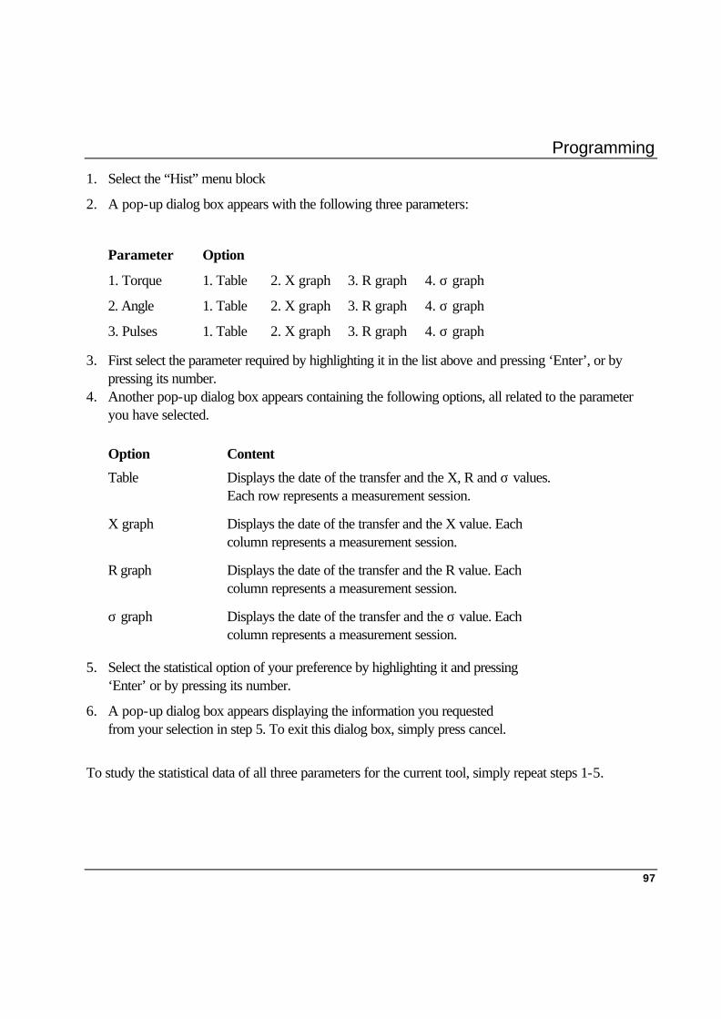
Programming
97
1. Select the “Hist” menu block
2. A pop-up dialog box appears with the following three parameters:
Parameter Option
1. Torque 1. Table 2. X graph 3. R graph 4. σ graph
2. Angle 1. Table 2. X graph 3. R graph 4. σ graph
3. Pulses 1. Table 2. X graph 3. R graph 4. σ graph
3. First select the parameter required by highlighting it in the list above and pressing ‘Enter’, or by pressing its number.
4. Another pop-up dialog box appears containing the following options, all related to the parameter you have selected.
Option Content
Table Displays the date of the transfer and the X, R and σ values. Each row represents a measurement session.
X graph Displays the date of the transfer and the X value. Each column represents a measurement session.
R graph Displays the date of the transfer and the R value. Each column represents a measurement session.
σ graph Displays the date of the transfer and the σ value. Each column represents a measurement session.
5. Select the statistical option of your preference by highlighting it and pressing ‘Enter’ or by pressing its number.
6. A pop-up dialog box appears displaying the information you requested from your selection in step 5. To exit this dialog box, simply press cancel.
To study the statistical data of all three parameters for the current tool, simply repeat steps 1-5.


Measuring Strategies
99
9. Measuring Strategies 9.1 General In the previous section we explained how to program your ACTA 3000. Now let us look at examples of different measuring strategies. Below, you can see how the measurement parameters in the “Program” menu block can be applied when measuring different tools. Note! The curves displayed below do not fully represent actual tightening curves. Their shapes are relevant only to illustrate the “Program” measurement parameters
Measured angle can now be selected for measurement at peak torque, max. angle or cycle complete.
Time
Direct Driven ToolsTorque
Cycle Start
Start Angle
PeakValue
Cycle Complete
Torque Min
Torque Max
Angle MaxAngle Min
Angle
End Time End Time
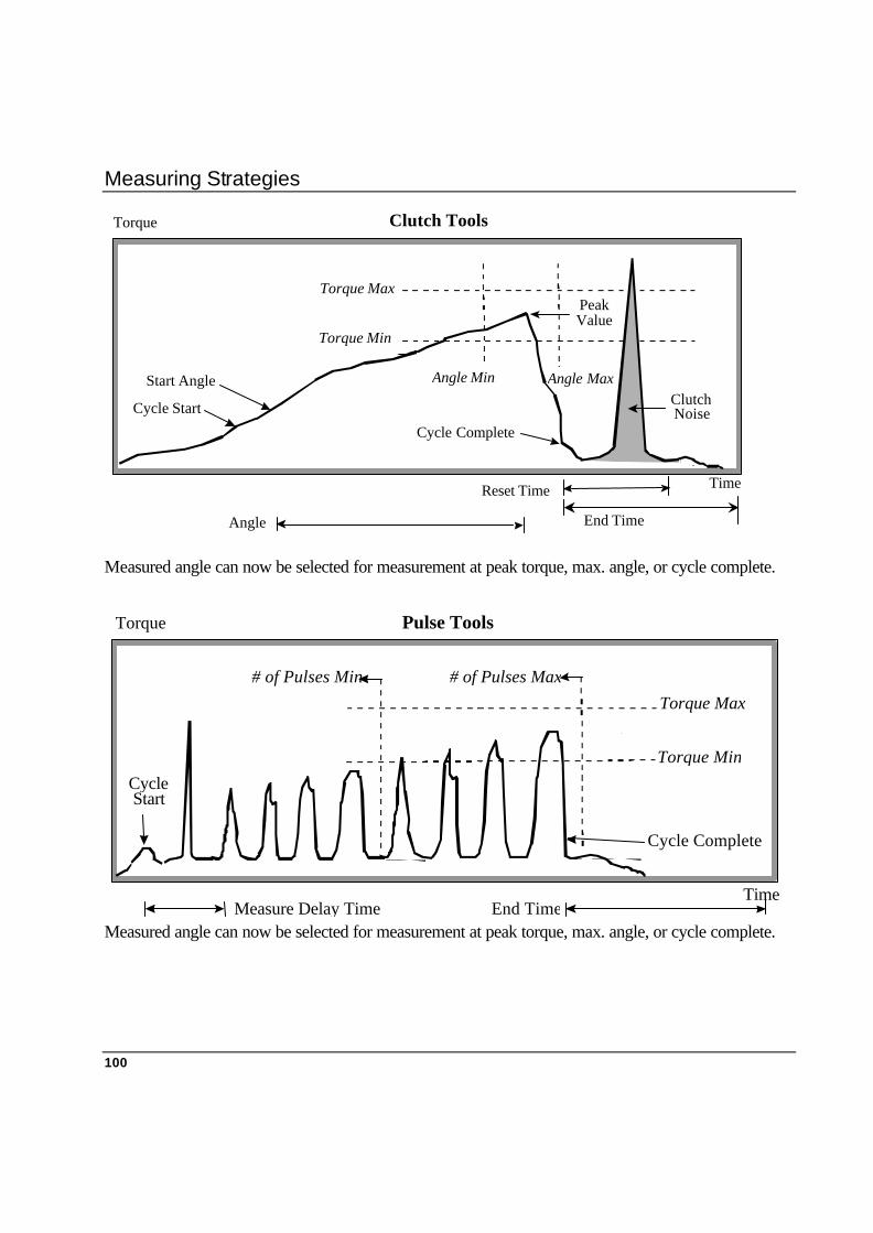
Measuring Strategies
100
Measured angle can now be selected for measurement at peak torque, max. angle, or cycle complete.
Measured angle can now be selected for measurement at peak torque, max. angle, or cycle complete.
Time
Clutch ToolsTorque
Cycle Start
Start Angle
PeakValue
Torque Min
Torque Max
Angle Max
Angle
Reset Time
Cycle Complete
ClutchNoise
Angle Min
End Time
Time
Cycle Complete
Pulse ToolsTorque
Cycle Start
Torque Min
Torque Max # of Pulses Min
Measure Delay Time End Time
# of Pulses Max
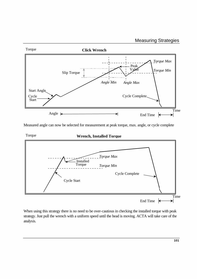
Measuring Strategies
101
Measured angle can now be selected for measurement at peak torque, max. angle, or cycle complete
When using this strategy there is no need to be over-cautious in checking the installed torque with peak strategy. Just pull the wrench with a uniform speed until the head is moving. ACTA will take care of the analysis.
Wrench, Installed TorqueTorque
End Time
InstalledTorque Torque Min
Torque Max
Time
Cycle Complete
Cycle Start
Click WrenchTorque
Cycle Start
Start Angle
Angle End Time
PeakValue Torque Min
Torque Max
Angle MaxAngle Min
Slip Torque
Time
Cycle Complete

Measuring Strategies
102
Peak Value The maximum torque level detected during the tightening cycle.
Installed Torque The torque value saved when strategy is Wench and Installed Torque
Filter Frequency (Not Shown)
The filter frequency used when interpreting signals from the torque transducer
Tightening Cycle (Not Shown)
Represents a complete measurement. It is defined as the interval from cycle start to the end of end time
Angle Is the actual angle presented on the display
Cycle Start The torque level at which the tightening cycle begins.
Cycle Complete The torque level at which the measurement is considered to be complete. It must be lower than cycle start.
Start Angle The level, expressed as torque, when angle measurement starts. Start angle should be equal to or higher than cycle start.
Measure Delay Time
The time after cycle start during which no signals are measured. This allows the ACTA 3000 to ignore initial “torque peaks”.
Reset Time The time after cycle complete during which no signals are measured. This allows the ACTA 3000 to ignore “clutch noise”.
End Time The time after cycle complete when, if the torque level again climbs above the cycle start level, the tightening cycle will continue. If the torque level does not climb above the cycle start during this time, the cycle is completed
Slip Torque The negative step required to start measurement of the breakaway level.
Min. Torque The minimum torque allowed for an accepted tightening operation on the current application. Relates to the application, not the tool.
Max Torque The maximum torque allowed for an accepted tightening on the current application. Related to the application, not the tool.
Min. Angle The minimum angle allowed for an accepted tightening operation on the current application. Relates to the application, not the tool.
Max. Angle The maximum angle allowed for an accepted tightening operation on the current application. Relates to the application, not the tool.
Angle complete Angle complete selection selects the criteria for measuring the final angle.
Min. no. of Pulses The minimum number of pulses allowed for an accepted tightening operation on the current application. Relates to the application, not the tool.
Max. no. of Pulses The maximum number of pulses allowed for an accepted tightening operation on the current application. Relates to the application, not the tool.

Measurement Results
103
10. Measurement Results 10.1 General On the following pages we will examine the different measurement windows and the information they provide during your measurement.
10.2 Basic Measurement Window This is the standard window in ACTA 3000 Basic. It is also available in the Quality Control and Advanced Analysis versions and can be selected under the “View” menu block.
When initiating measurements this is the information it provides:
1 4 12 2
11 9
1. Power left in battery 7. Measured torque
2. Number of tightening operations 8. Measured angle
3. X-bar 9. Number of pulses
4. Unit 10. Last five tightening operations
5. Confidence interval neg. 11. Softkey text
6. Confidence interval pos. 12. Filter frequency
1. Power left in battery This indicates how much power there is left in the
7 8
3 5 6 10
Measurement Results
104
1. Power left in battery This indicates how much power there is left in the battery. When the battery indicator is completely white the battery is fully charged and when the battery indicator is completely black the battery has less than 8% charge left.
2. Number of tightening operations
The number of tightening operations that have been performed.
3. X-bar The average value of all the measurements that have been performed. Located in the memory.
4. Unit The unit for torque (engineering unit).
5. Confidence interval neg. The lowest possible value with a confidence of more than 99 %.
6. Confidence interval pos. The highest possible value with a confidence of more than 99 %.
7. Measured torque The torque value.
8. Measured angle The current angle value. If there is no angle signal this field is empty.
9. Number of pulses If a Pulse-tool is selected, this field shows the number of pulses for the last tightening operation. If Hz is displayed after “No. of pulses”, pulse frequencies are displayed. If there is no pulse tool this field is empty.
10. Last five tightening operations
The last tightening operation entered in the memory. With each new tightening operation the result is displayed at the top and the old results are moved down. When the memory is empty this field is empty.
11. Softkey text The softkey text represents the main menus of the current programming tree and is operated by the 5 buttons located below the display. Each softkey field displays the functionality of each button.
12. Filter frequency Filter frequency, visible for pulse tool.
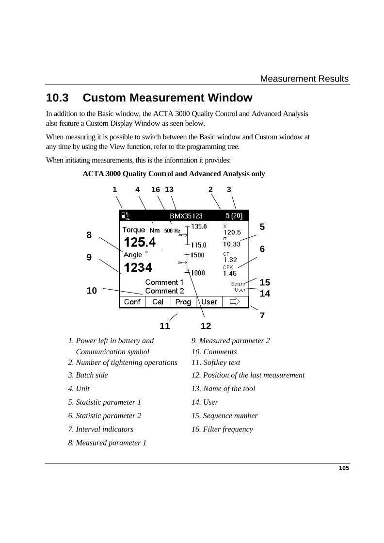
Measurement Results
105
10.3 Custom Measurement Window In addition to the Basic window, the ACTA 3000 Quality Control and Advanced Analysis also feature a Custom Display Window as seen below.
When measuring it is possible to switch between the Basic window and Custom window at any time by using the View function, refer to the programming tree.
When initiating measurements, this is the information it provides:
ACTA 3000 Quality Control and Advanced Analysis only
1 4 16 13 2 3 11 12
1. Power left in battery and 9. Measured parameter 2 Communication symbol 10. Comments 2. Number of tightening operations 11. Softkey text
3. Batch side 12. Position of the last measurement
4. Unit 13. Name of the tool
5. Statistic parameter 1 14. User
6. Statistic parameter 2 15. Sequence number
7. Interval indicators 16. Filter frequency
8. Measured parameter 1
5 6 15 14 7
8 9 10
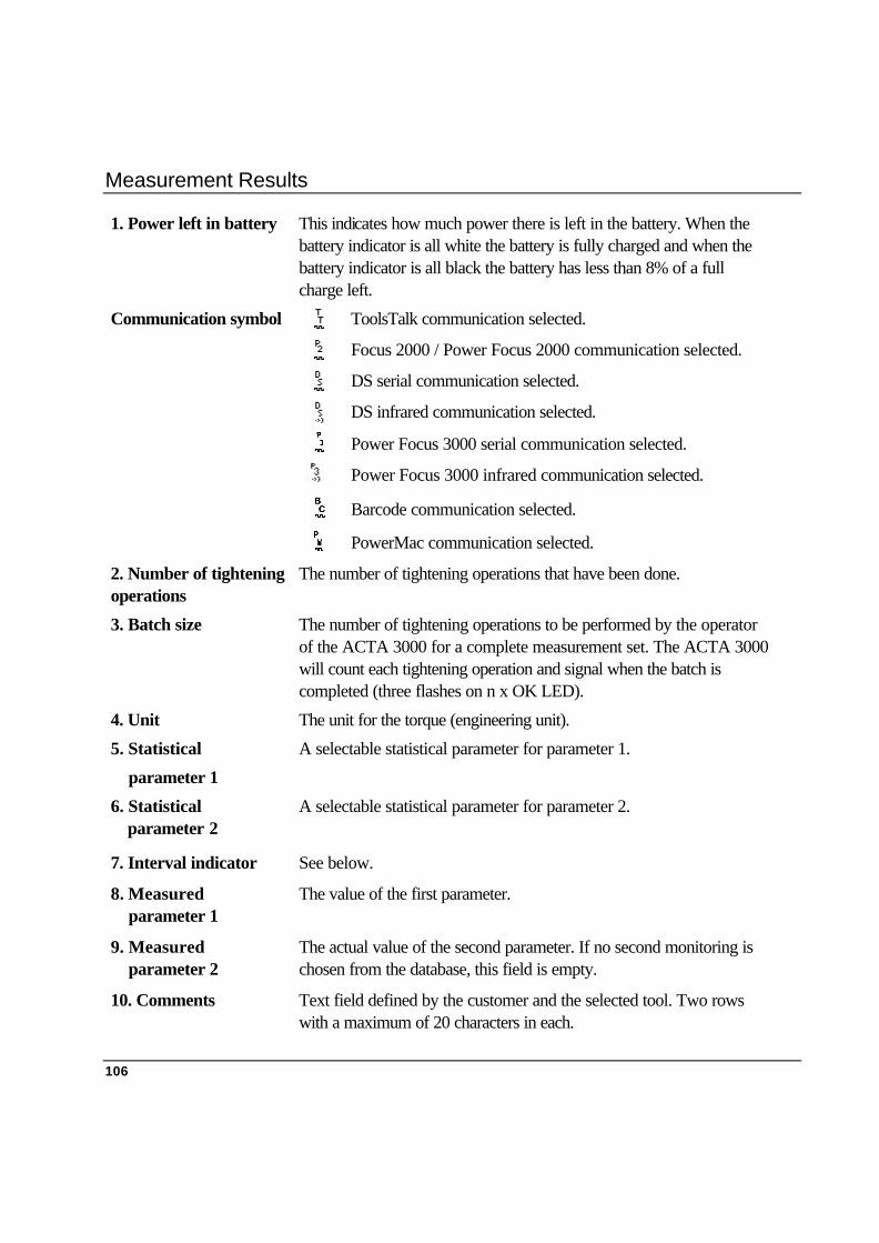
Measurement Results
106
1. Power left in battery This indicates how much power there is left in the battery. When the battery indicator is all white the battery is fully charged and when the battery indicator is all black the battery has less than 8% of a full charge left.
Communication symbol ToolsTalk communication selected.
Focus 2000 / Power Focus 2000 communication selected.
DS serial communication selected.
DS infrared communication selected.
Power Focus 3000 serial communication selected.
Power Focus 3000 infrared communication selected.
Barcode communication selected.
PowerMac communication selected.
2. Number of tightening operations
The number of tightening operations that have been done.
3. Batch size The number of tightening operations to be performed by the operator of the ACTA 3000 for a complete measurement set. The ACTA 3000 will count each tightening operation and signal when the batch is completed (three flashes on n x OK LED).
4. Unit The unit for the torque (engineering unit).
5. Statistical
parameter 1
A selectable statistical parameter for parameter 1.
6. Statistical parameter 2
A selectable statistical parameter for parameter 2.
7. Interval indicator See below.
8. Measured parameter 1
The value of the first parameter.
9. Measured parameter 2
The actual value of the second parameter. If no second monitoring is chosen from the database, this field is empty.
10. Comments Text field defined by the customer and the selected tool. Two rows with a maximum of 20 characters in each.

Measurement Results
107
11. Softkey text The softkey text represents the main menus of the current programming tree and is operated by the 5 buttons located below the display. Each softkey field displays the functionality of each button.
12. Position of the last measurement
The arrow indicates where the value is located between the min. and the max. value for the selected tool. See below.
Position of the last measurement
Max. accept value
Min. accept value
When a value falls outside a max. or min. limit, the arrow is at the top or bottom respectively and flashing.
13. Name of tool Name of tool.
14. User User, visible if defined.
15. Sequence number Sequence number, visible if defined.
16. Filter frequency Filter frequency, visible for pulse tool.

Measurement Results
108
10.4 Trace Measurement Window In addition to the Basic and Custom Display Window, the ACTA 3000 Advanced Analysis also features a Trace Display Window as seen below. When measuring, it is possible to switch between the Torque, Custom and Trace windows at any time. When initiating measurements, this is the information it provides: ACTA 3000 Advanced Analysis only
1. Power left in battery and 6. Peak point
Communication symbol 7. Peak torque
2. Scale X-vice 8. Measured angle
3. Scale Y-vice left 9. Softkey text
4. Scale Y-vice right 10. Name of the tool
5. Angle start point
1 7 8 5 3
10
6 4 2
9
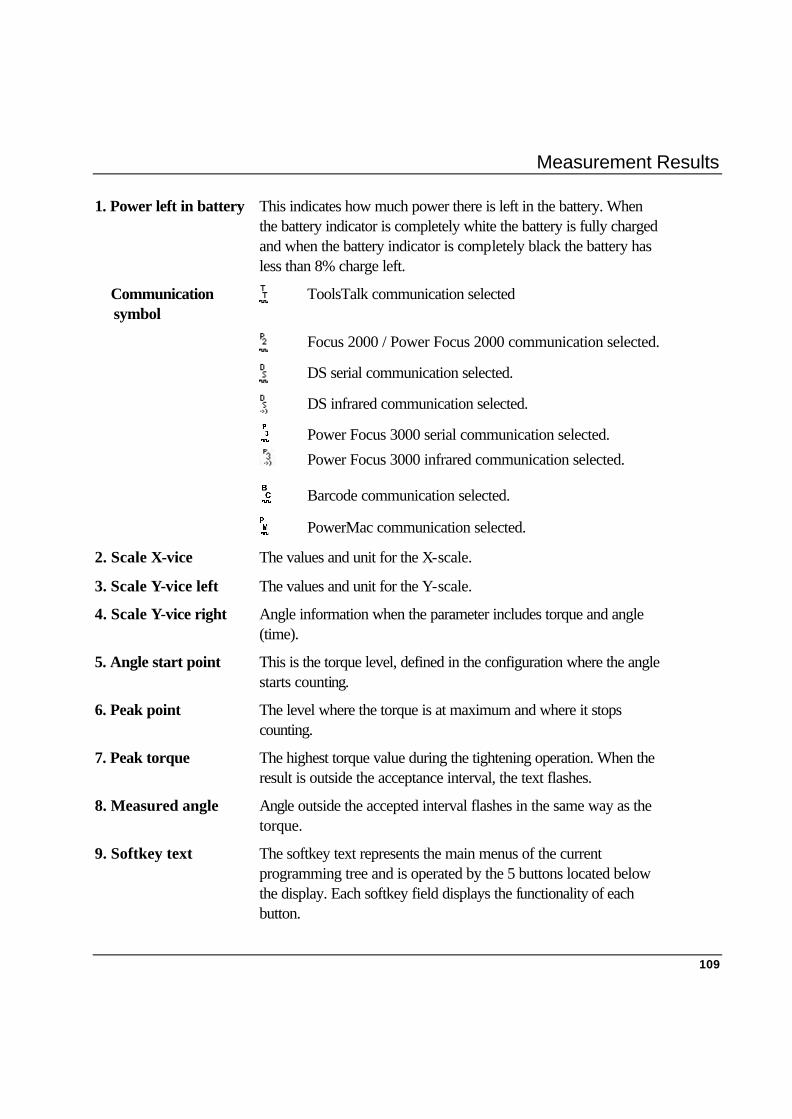
Measurement Results
109
1. Power left in battery This indicates how much power there is left in the battery. When the battery indicator is completely white the battery is fully charged and when the battery indicator is completely black the battery has less than 8% charge left.
Communication symbol
ToolsTalk communication selected
Focus 2000 / Power Focus 2000 communication selected.
DS serial communication selected.
DS infrared communication selected.
Power Focus 3000 serial communication selected.
Power Focus 3000 infrared communication selected.
Barcode communication selected.
PowerMac communication selected.
2. Scale X-vice The values and unit for the X-scale.
3. Scale Y-vice left The values and unit for the Y-scale.
4. Scale Y-vice right Angle information when the parameter includes torque and angle (time).
5. Angle start point This is the torque level, defined in the configuration where the angle starts counting.
6. Peak point The level where the torque is at maximum and where it stops counting.
7. Peak torque The highest torque value during the tightening operation. When the result is outside the acceptance interval, the text flashes.
8. Measured angle Angle outside the accepted interval flashes in the same way as the torque.
9. Softkey text The softkey text represents the main menus of the current programming tree and is operated by the 5 buttons located below the display. Each softkey field displays the functionality of each button.

Measurement Results
110
The Trace Display Window can easily be configured to display traces of Torque and Angle, Torque and Time or, as shown below on the left, Torque and Angle over Time. Refer to the chapter entitled Programming the ACTA 3000, menu block “Param.” (Parameters) for instructions.
Torque and Angle over Time Graph
The Trace Display Window also features a Zoom function. If an area of the tightening operation curve needs to be studied in detail, it can be magnified by zooming-in up to five times. Refer to the chapter entitled Programming the ACTA 3000, menu block “Param” (Parameters) for instructions.
Cancel

Measurement Results
111
10.5 Batch Result window
As explained in Programming the ACTA 3000, under menu block Prog, Programming, there is an option to activate “Batch” on the ACTA 3000 Quality Control and Advanced Analysis versions.
In practice, this function will cause the ACTA 3000 to check and provide statistical status of Torque, Angle and (Pulses) after a specific number of measurements - your specified batch. This is what your ACTA 3000 then checks. The batch result is OK when:
Torque and angle
1. All values above min.
2. All values below max.
3. All subgroup X-bars above LCLx.
4. All subgroup X-bars below UCLx.
5. All subgroup ranges above LCLr.
6. All subgroup ranges below UCLr.
7. CP higher than CP>.
8. CPK higher than CPK>-
9. CAM higher than CAM>.
10. Diff % lower than Diff %<
Number of pulses
1. All value above min.
2. All values below max.
Note!
You have to set limits for the above parameters in order for this to work. Set your limits in Statistical setup in the Prog, (Programming) menu block.
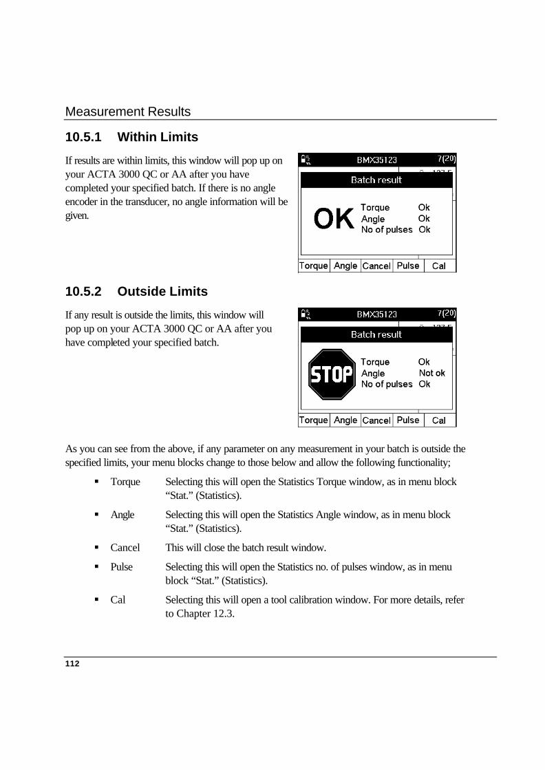
Measurement Results
112
10.5.1 Within Limits
If results are within limits, this window will pop up on your ACTA 3000 QC or AA after you have completed your specified batch. If there is no angle encoder in the transducer, no angle information will be given.
10.5.2 Outside Limits
If any result is outside the limits, this window will pop up on your ACTA 3000 QC or AA after you have completed your specified batch.
As you can see from the above, if any parameter on any measurement in your batch is outside the specified limits, your menu blocks change to those below and allow the following functionality;
§ Torque Selecting this will open the Statistics Torque window, as in menu block “Stat.” (Statistics).
§ Angle Selecting this will open the Statistics Angle window, as in menu block “Stat.” (Statistics).
§ Cancel This will close the batch result window.
§ Pulse Selecting this will open the Statistics no. of pulses window, as in menu block “Stat.” (Statistics).
§ Cal Selecting this will open a tool calibration window. For more details, refer to Chapter 12.3.

Calibration
113
11. Calibration 11.1 Calibrating the ACTA 3000
To calibrate the ACTA 3000, we recommend contacting your local Atlas Copco Tools sales/service representative. For ACTA 3000 calibration, a traceable calibrated reference transducer box with cable is needed, part no. 4222 0270 85. Carry out ACTA 3000 reference transducer box calibration by selecting “Conf” or “Calibration” and “ACTA” (Conf-2-1). When calibrating, follow the information windows that are displayed.
Note! § If there are less than 30 days to the next calibration date, a message window
appears telling the operator that the ACTA 3000 should be calibrated before the next calibration date.
§ If the next calibration date has passed, a message window appears telling the operator that the ACTA 3000 should be calibrated.

Calibration
114
ACTA CALIBRATION REPORT 1(1) Acta serial number Date Time 047001 Jun 21 2000 10:55.12 PREVIOUS CALIBRATION DATE Mar 08 1999 REFERENCE BOX NUMBER........... 1234 OTHER EQUIPMENT.......................................
......................................................
CALIBRATION RESULT OK ADJUSTMENT 0.59 mV/V OFFSET COMP 0.05 % GAIN COMP 0.25 % ADJUSTMENT 2.0 mV/V OFFSET COMP -0.11 % GAIN COMP 0.44 % NEXT CALIBRATION DATE Jun 21 2001 ADDITIONAL INFORMATION................................
......................................................
......................................................
THE REFERENCE BOX IS TRACEABLE CALIBRATED. THIS REPORT DOCUMENTS THE TRACEABILITY TO NATIONAL STANDARDS FOR ALL EQUIPMENT USED FOR THE CALIBRATION. SIGNATURE ..........................
Calibration
115
11.2 Calibrating Transducers with the ACTA 3000 Available in Basic, Quality Control and Advanced Analysis versions.
The ACTA 3000 has a built-in feature that allows calibration of transducers using the deadweight method. Note!
When performing this task, the use of certified deadweight equipment (arm and weight) is needed.
In addition, if an Atlas Copco memory transducer is used and calibrated by means of the above method, it will be possible to download the new calibration value to the memory of the transducer directly from the ACTA 3000.
1. Place the transducer to be calibrated in the deadweight equipment.
2. Connect the transducer to the ACTA 3000.
3. Select transducer calibration by pressing the “Conf” softkey. Select “Calibration” and “Deadweight” (Conf-3-2).
4. Select Deadweight by highlighting it and pressing ‘Enter’ or by pressing number 2 on the keypad.
5. Select OK - press ‘OK’ on the keypad or highlight the OK icon followed by ‘Enter’.
6. A “Deadweight calibration” window appears with the following text:
Number of load points This is the current status of the number of full measurements for your calibration.
No. of load points -> No. of cal. points.
No load on transducer Gives the required torque status of the transducer.
Measured value (mV/V) This refers to the numeric value below and represents your measured mV/V value under the current load on the transducer.
(Numeric value) Below this window, three new functionality specific menu blocks appear for the calibration process:
Save Lin.ch Cancel

Calibration
116
11.2.1 Calibration Measure and record the mV/V value of the transducer at least three consecutive times. Three measurements is the minimum recommended number of reference points.
Each measurement includes an mV/V checkpoint without any torque applied over the transducer and one checkpoint when a specific torque level is applied over the transducer using the deadweight equipment.
These measurement results or calibration checkpoints will serve as the basis on which the ACTA 3000 calculates a calibration value, which is then compared with the current calibration values of the transducer.
7. You are in the “Deadweight calibration” window as described in step 6.
Now press the ‘Save’ menu block to save the first checkpoint (mV/V value) with no load on the transducer.
8. The first checkpoint without load is saved and you can see that row number 2 in the “Deadweight calibration” window changes and now reads: Load on transducer.
9. Apply torque to the transducer using the deadweight equipment. As you apply torque you can see that the mV/V value changes – it increases.
10. When the load is stable, press the ‘Save’ menu block again.
11. A small pop-up window appears asking you to input a torque value manually. The torque value you input here is the value produced by your “Deadweight equipment” when you pressed ‘Save’ in step 11.
12. When you have entered your torque value, press ‘Enter’. The first checkpoint with load is saved and you can see that rows 1 and 2 in the “Deadweight calibration” window change and now read: “Number of cal. points 1” and “No Load on transducer” respectively.
13. Remove applied torque on the transducer.
You have now completed the first full reference mV/V measurement for this transducer, both at rest and at a specific torque value.
14. Now repeat steps 7-13 at least two more times.
15. When you have done this, the "Deadweight calibration” window should display “Number of cal. points 3” confirming that three full reference mV/V measurements have been completed.
Calibration
117
11.2.2 Linearity check
When the above calibration measurement values have been recorded and saved, perform a linearity check to see how consistent the transducer is.
Measure and record the mV/V value of the transducer (2) two consecutive times and, just as for the calibration check above, a full linearity measurement or checkpoint includes a mV/V checkpoint without any torque applied over the transducer and a checkpoint when a specific torque level is applied over the transducer using the deadweight equipment.
No. of cal. points -> No. of lin. points.
16. Press the “lin ch.” menu block. The “Deadweight measurement” window displays the following:
Number of cal. points This is your current status of the number of full linearity checks for your calibration.
Load on transducer Gives you the torque status of the transducer.
Measured value (mV/V) This refers to the numeric value below and represents your measured mV/V value under the current load on the transducer.
(Numeric value)
Below this window, three new functionality specific menu blocks appear for the linearity check process:
Save Cancel Ready
17. Place the transducer on your joint and then apply torque to the transducer using the Deadweight equipment. As you apply torque you can see that the mV/V value changes – it increases.
18. When the torque is stable, press the ‘Save’ menu block again.

Calibration
118
19. A small pop-up window appears asking you to input a torque value manually. The torque value you input here is the value produced by your “Deadweight equipment” when you pressed ‘Save’ in step 20.
20. When you have entered your torque value, press ‘Enter’. The first checkpoint with load is now saved and you can see that row number 1 and 2 in the “Deadweight calibration” window have changed and now read: “Number of cal. points 1” and “Load on transducer” respectively.
21. You have now completed the first full linearity check measurement for this transducer, both at rest and at a specific torque value.
22. If you need to, repeat steps 18-22.
23. When you have done this, the “Deadweight calibration” window should display “Number of cal. points 3” confirming that three full linearity check measurements have been completed.
11.2.3 Saving and printing the new calibration value
24. Now press the ‘Ready’ menu block.
25. Another window appears asking if you would like a printout. The printout is a full calibration report of the above process. Refer to the example on the following page.
26. Choose a printout or simply press cancel.
27. Press ‘Save’ if the new values are to be saved in the transducer memory. Two questions are asked. The first is the name of the user. The second is the next calibration date. The next calibration date will be used to display a message if the date has expired or if there are less than 30 days to the next calibration of the transducer, refer to 11.1 Calibrating the ACTA 3000.
28. The “Deadweight calibration” window now displays the old (current) calibration value of the transducer and the new (now measured) calibration value. You are also asked if you wish to save the new value in the memory of the transducer. This is possible if you use an Atlas Copco memory transducer.
29. To save, select ‘OK’. If the transducer is not an Atlas Copco memory transducer or if you do not wish to save the new cal. value, select ‘Cancel’ in the “Deadweight calibration” window.
After this you will have finished calibrating your transducer and the measurement window on the ACTA 3000 will return. Remember to mark the new calibration value on your transducer.
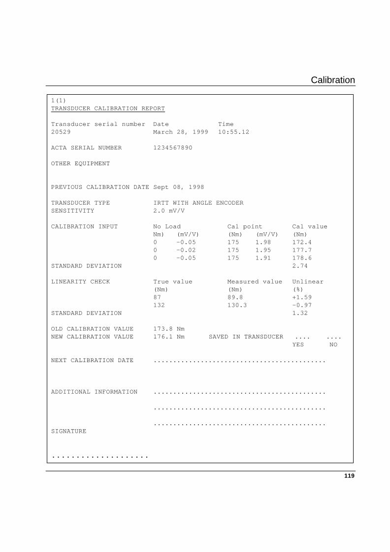
Calibration
119
1(1) TRANSDUCER CALIBRATION REPORT Transducer serial number Date Time 20529 March 28, 1999 10:55.12 ACTA SERIAL NUMBER 1234567890 OTHER EQUIPMENT PREVIOUS CALIBRATION DATE Sept 08, 1998 TRANSDUCER TYPE IRTT WITH ANGLE ENCODER SENSITIVITY 2.0 mV/V CALIBRATION INPUT No Load Cal point Cal value Nm) (mV/V) (Nm) (mV/V) (Nm) 0 -0.05 175 1.98 172.4 0 -0.02 175 1.95 177.7 0 -0.05 175 1.91 178.6 STANDARD DEVIATION 2.74 LINEARITY CHECK True value Measured value Unlinear (Nm) (Nm) (%) 87 89.8 +1.59 132 130.3 -0.97 STANDARD DEVIATION 1.32 OLD CALIBRATION VALUE 173.8 Nm NEW CALIBRATION VALUE 176.1 Nm SAVED IN TRANSDUCER .... .... YES NO NEXT CALIBRATION DATE ............................................ ADDITIONAL INFORMATION ............................................ ............................................ ............................................ SIGNATURE ....................

Calibration
120
11.3 Tool calibration
Available in Quality Control and Advanced Analysis.
Tool calibration can be activated with the ‘Conf.’ softkey. Select “Calibration” and “Tool” or the ‘Cal.’ softkey in the “Batch result” window.
See the table below on setting up parameters for tool calibration.
When performing Tool Calibration, it is important that the parameters in Prog / 1 Tool type are correctly programmed.
When selecting the “Tool type” setup a pop-up window appears with a number of parameters:
1. Tool type You can select Direct Driven, Pulse, Wrench or Click Wrench.
2. Target torque Used in “None” or “DS” tool calibration and corresponds to the target torque setting in the manual non-controlled tool (None) or the DS-controlled tool (DS).
3. Controller Used in tool calibration to select the type of controller to calibrate. There are 4 types:
None
Other controller
F2000/PF2000
DS
PF3000
PowerMac
“None” is used for handheld or non-controlled tools.
“Other controller” is used for unknown or unsupported controlled tools. Manual input of controller tightening operation values is required.
“F2000/PF2000” is used for Focus 2000 and Power Focus 2000 controlled tools. If selected, controller tightening operation values are automatically received from the controller after each tightening operation.
Calibration
121
“DS” is used for DS-controlled tools. If selected, no tightening values are read from the controller after each tightening operation.
“PF3000” is used for Power Focus 3000 controlled tools. If selected, controller tightening operation values are automatically read from the controller after each tightening operation. No tightening values are read from controller for “PF3000” model “Tensor DS”.
“PowerMacs” are used for PowerMac controlled tools. If selected, controller tightening operation values are automatically read from the controller after each tightening operation.
4. Calibration torque
Used in “Other controller”, “F2000/PF2000” or “PF3000” tool calibration and corresponds to the calibration torque in the unknown or unsupported controlled tools (Other controller), the F2000/PF2000 controller (F2000/PF2000) or PF3000 controller (PF3000).
4. Tuning factor Used in “DS” tool for the torque tuning factor.
Also used in “PF3000” with tool model “Tensor DS”.
5. Communication
Used in tool calibration for selecting the type of communication to be used. For each type of controller, “Manual input” or “RS232” can be selected. For the DS controller, “Infrared” can also be selected. When selecting “Manual input”, the user is asked for controller torque and controller angle in input fields after each tightening operation. When selecting “RS232” or “Infrared”, controller tightening values are automatically read from the controller after each tightening operation.
6. Parameter set Used in “F2000/PF2000”, “DS” and “PF3000” tool calibration for selecting the parameter set used when calibrating.
7. Cell ID/Unit ID
Used in PF3000 tool calibration to select cell and in Focus 2000/PF2000 to select unit ID.
8. Channel Used in Focus 2000/PF2000 and PF3000 tool calibration to select channel.
9. Model Used in PF3000 tool calibration to select tool model. You can choose between Tensor S or Tensor DS.
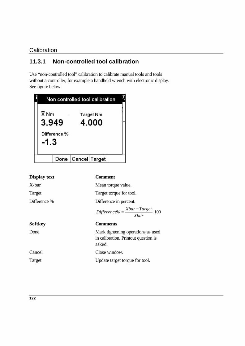
Calibration
122
11.3.1 Non-controlled tool calibration
Use “non-controlled tool” calibration to calibrate manual tools and tools without a controller, for example a handheld wrench with electronic display. See figure below.
Display text Comment
X-bar Mean torque value.
Target Target torque for tool.
Difference % Difference in percent.
100⋅−
=Xbar
TargetXbar%Difference
Softkey Comments
Done Mark tightening operations as used in calibration. Printout question is asked.
Cancel Close window.
Target Update target torque for tool.

Calibration
123
11.3.2 Other controller calibration
Use “Other controller” calibration to calibrate unknown or unsupported controlled tools. The controller torque values must be entered manually. A new calibration torque is calculated for the controller. See the figure below.
Display text Comments
X-bar Mean torque value.
X-bar Contr. Mean controller torque. The controller torque values are entered manually.
New cal. torque New calculated calibration torque for controller.
XbarContrXbar
ueOldcaltorqueNewcaltorq ⋅=
Softkey Comments
Done Mark tightening operations as used in calibration. Printout question is asked.
Cancel Close window.
Edit Change the calculated calibration torque.

Calibration
124
11.3.3 DS calibration
Use DS torque tuning to calculate a new factor for a DS controller. The new torque tuning factor is calculated with communication setup to the controller, the new factor can be written in the controller/tool. See the figure below.
Display text Comments
Drive ID Controller identification
P-Set Parameter set used
X-bar Mean torque value.
Target Target torque for controller.
New factor New calculated factor for
controller/tool.
OldfactorXbar
TargetNewfactor ⋅=
Old factor Old factor value in controller/tool.

Calibration
125
Softkey Comments
Read 1 Read old factor from controller/tool.
Save 2 Save new calculated factor in controller/tool. Tightening operations are marked used in calibration. Printout question is asked.
Done 3 Mark tightening operations as used in calibration. Printout question is asked.
Cancel Close window.
Target Update target torque.
Edit Change the calculated factor.
1 Only if “RS232” or “Infrared” communication is selected.
2 Only if “RS232" or “Infrared” communication is selected.
3 Only if “Manual input” communication is selected. Replaces “Save”.

Calibration
126
11.3.4 Power Focus 2000 calibration
Use Focus 2000 / Power Focus 2000 calibration to calibrate a Focus 2000 / Power Focus 2000 controller. A new calibration torque value will be calculated. The new value can be saved in the controller if communication is set up to the controller. See figure below.
Display text Comments
P-Set Parameter set used.
X-bar Mean torque value.
X-bar Contr. Mean controller torque. Values are manually entered or read from controller. Manually entered if communication not set up to controller.
New cal. torque New calculated calibration torque for controller.
XbarContrXbar
ueOldcaltorqueNewcaltorq ⋅=
Old cal. torque Old calibration torque in controller.
Softkey Comments
Done Mark tightening operations as used in calibration. Printout question is asked.
Cancel Close window.
Edit Change the calibration torque.

Calibration
127
11.3.5 Power Focus 3000 calibration
Use Power Focus 3000 calibration to calibrate a Power Focus 3000 controller.
Torque tuning of Power Focus 3000 with Tensor DS tool connected is done in the same way as torque tuning a DS controller (refer to DS calibration). Tool model Tensor S connected, see the calibration description below.
A new calibration torque value will be calculated. The new value can be saved in the controller if communication is set up to the controller. See the figure below.
Display text Comments
P-Set Parameter set used.
X-bar Mean torque value.
X-bar Contr. Mean controller torque. Values are manually entered or read from controller. Manually entered if communication not set up to controller.
New cal. torque New calculated calibration torque for controller.
XbarContrXbar
ueOldcaltorqueNewcaltorq ⋅=
Old cal. torque Old calibration torque in controller.
PF3000 calibration
Calibration
128
Softkey Comments
Read 4 Read values from controller.
Save 5 Save new calculated calibration torque in controller. Tightening operations are marked used in calibration. Printout question is asked.
Done 6 Mark tightening operations as used in calibration. Printout question is asked.
Cancel Close window.
Edit Change the calibration torque.
4 Only if “RS232” or infrared communication is selected.
5 Only if “RS232” or infrared communication is selected.
6 Only if “Manual input” communication is selected. Replaces “Save”.
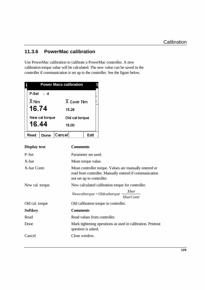
Calibration
129
11.3.6 PowerMac calibration
Use PowerMac calibration to calibrate a PowerMac controller. A new calibration torque value will be calculated. The new value can be saved in the controller if communication is set up to the controller. See the figure below.
Display text Comments
P-Set Parameter set used.
X-bar Mean torque value.
X-bar Contr. Mean controller torque. Values are manually entered or read from controller. Manually entered if communication not set up to controller.
New cal. torque New calculated calibration torque for controller.
XbarContrXbar
ueOldcaltorqueNewcaltorq ⋅=
Old cal. torque Old calibration torque in controller.
Softkey Comments
Read Read values from controller.
Done Mark tightening operations as used in calibration. Printout question is asked.
Cancel Close window.
Power Macs calibration
Done
Calibration
130
11.3.7 Example, how to perform a calibration
In the example below we give one example of how to perform a calibration. This is only possible with an ACTA 3000 QC or AA. 1. Set up your ACTA 3000 for the calibration.
Connect the proper transducer for this calibration and wait a few seconds for the shunt calibration.
You probably already have the tool you are going to calibrate in your database. If not, you need to create the correct program. Create the tool by pressing “Database / 1 New tool” and enter a new tool ID used for this calibration. When using a controlled Atlas Copco Tool: • Connect the ACTA 3000 and the controller (PF, DS or PowerMac) with the serial cable. • Hold the ACTA 3000 in Infrared position (PF 3000, DS). Synchronise by pressing “Q.Prog / 5 Synchronise” and select your choice of tool. Depending on your choice you may need to answer a few more questions before the command is completed.
2. Perform tightening.
Remove all tightening from this tool by pressing ‘Shift’ and then “Cl”. Select custom window by pressing “‘View’ / 2 Custom”. Attach the transducer to the tool and perform the tightening. If you are running a transducerised Atlas Copco tool both transducer torque and controller torque will appear automatically in the ACTA 3000 window. If you running a transducerised tool from another manufacturer, ACTA 3000 will ask for the torque value. If you have an angle transducer ACTA 3000 will ask for the controller angle. Otherwise you will only see the result from the transducer on the display.
Carry out a total of 25 tightenings.
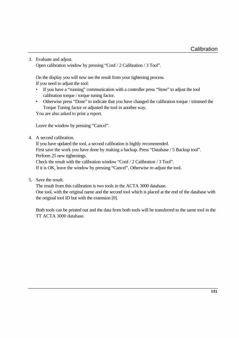
Calibration
131
3. Evaluate and adjust. Open calibration window by pressing “Conf / 2 Calibration / 3 Tool”. On the display you will now see the result from your tightening process. If you need to adjust the tool: • If you have a “running” communication with a controller press “Store” to adjust the tool
calibration torque / torque tuning factor. • Otherwise press “Done” to indicate that you have changed the calibration torque / trimmed the
Torque Tuning factor or adjusted the tool in another way. You are also asked to print a report. Leave the window by pressing “Cancel”.
4. A second calibration.
If you have updated the tool, a second calibration is highly recommended. First save the work you have done by making a backup. Press “Database / 5 Backup tool”. Perform 25 new tightenings. Check the result with the calibration window “Conf / 2 Calibration / 3 Tool”. If it is OK, leave the window by pressing “Cancel”. Otherwise re-adjust the tool.
5. Save the result.
The result from this calibration is two tools in the ACTA 3000 database. One tool, with the original name and the second tool which is placed at the end of the database with the original tool ID but with the extension [0]. Both tools can be printed out and the data from both tools will be transferred to the same tool in the TT ACTA 3000 database.


Printouts from the ACTA 3000
133
12. Printouts from the ACTA 3000 12.1 General
As explained under the “Print” menu block in the Programming the ACTA 3000 section, the ACTA 3000 features considerable print capabilities.
The following printouts can be produced by the ACTA 3000: Printout
• Continuous
• Tool rundowns
• Transducer info
• Tool setup
• Tool statistics
• Tool calibration
• All tool rundown
• All tool set-up
• All tool statistics
• All tool calibration
• Database summary
• Trace
Note!
If printing in colour, all underscored as well as LOW and HIGH values are printed in red.

Printouts from the ACTA 3000
134
CONTINUOUS REPORT Tool Identity: AB735 Number Torque Angle Pulses Status Date Time Nm deg 1 75.4 185 12 OK/OK/OK JUN 26 2000 09:57.23 2 76.7 155 13 OK/OK/OK JUN 26 2000 09:57.50 3 75.1 169 34 OK/OK/HIGH Jun 26 2000 09:58.15 Tool Identity: BB515 NUMBER TORQUE ANGLE PULSES STATUS DATE TIME 1 100.3 48 OK/OK/ - JUN 26 2000 10:13.20 2 101.8 50 OK/OK/ - JUN 26 2000 10:13.42 3 99.4 47 OK/OK/ - JUN 26 2000 10:14.12 4 100.3 52 OK/OK/ - Jun 26 2000 10:14.37 5 66.1 32 LOW/LOW/ - Jun 26 2000 10:15.08 5 - REMOVED - 5 104.1 56 OK/OK/ - Jun 26 2000 10:15.27 Tool Identity: AC125 Number Torque Angle Pulses Status Date Time (Nm) (deg) 138 245.1 OK/ - / - JUN 26 2000 13:15.10 139 299.7 HIGH/ - / - Jun 26 2000 13:15.24 140 256.3 OK/ - / - Jun 26 2000 13:15.38 Tool Identity: Number Torque Angle Pulses Status Date Time (Nm) (deg) 1 31.4 23 OK/OK/ - Jun 26 2000 14:13.07 2 25.5 22 OK/OK/ - Jun 26 2000 14:13.45 3 13.5 12 OK/OK/ - Jun 26 2000 14:33.59 TEST PERFORMED BY: AJN APPROVED BY: ...........................................
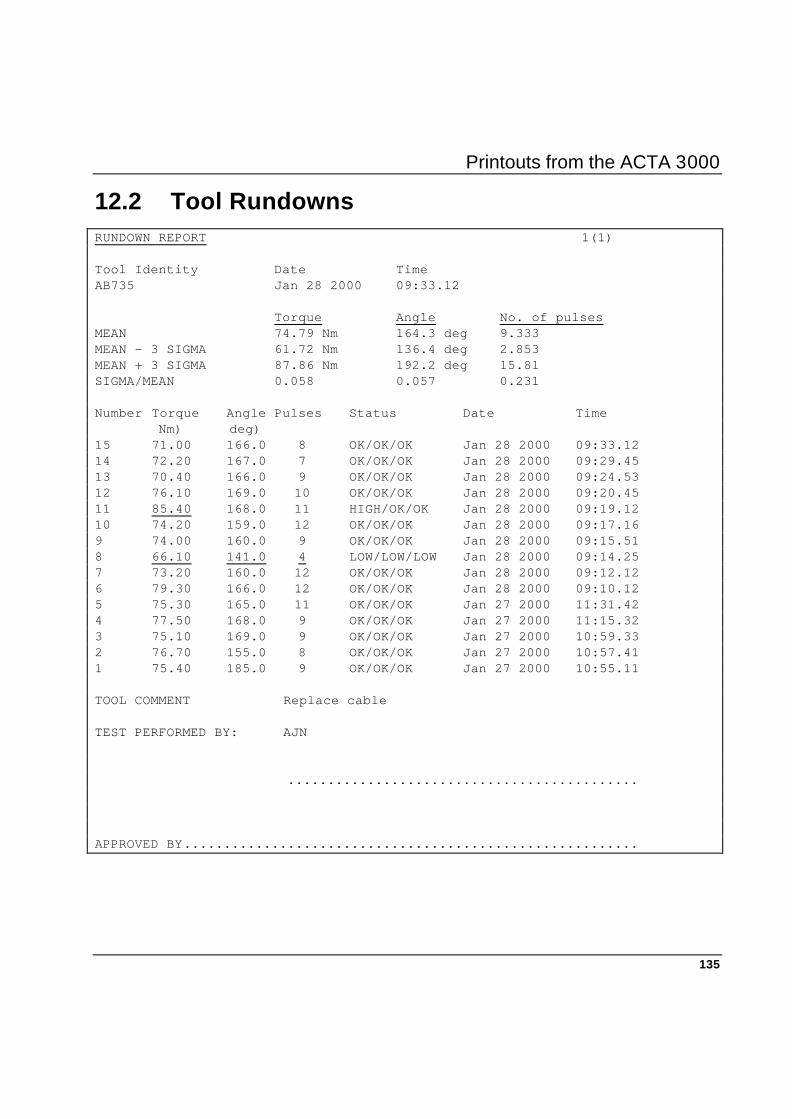
Printouts from the ACTA 3000
135
12.2 Tool Rundowns RUNDOWN REPORT 1(1) Tool Identity Date Time AB735 Jan 28 2000 09:33.12
Torque Angle No. of pulses MEAN 74.79 Nm 164.3 deg 9.333 MEAN - 3 SIGMA 61.72 Nm 136.4 deg 2.853 MEAN + 3 SIGMA 87.86 Nm 192.2 deg 15.81 SIGMA/MEAN 0.058 0.057 0.231 Number Torque Angle Pulses Status Date Time Nm) deg) 15 71.00 166.0 8 OK/OK/OK Jan 28 2000 09:33.12 14 72.20 167.0 7 OK/OK/OK Jan 28 2000 09:29.45 13 70.40 166.0 9 OK/OK/OK Jan 28 2000 09:24.53 12 76.10 169.0 10 OK/OK/OK Jan 28 2000 09:20.45 11 85.40 168.0 11 HIGH/OK/OK Jan 28 2000 09:19.12 10 74.20 159.0 12 OK/OK/OK Jan 28 2000 09:17.16 9 74.00 160.0 9 OK/OK/OK Jan 28 2000 09:15.51 8 66.10 141.0 4 LOW/LOW/LOW Jan 28 2000 09:14.25 7 73.20 160.0 12 OK/OK/OK Jan 28 2000 09:12.12 6 79.30 166.0 12 OK/OK/OK Jan 28 2000 09:10.12 5 75.30 165.0 11 OK/OK/OK Jan 27 2000 11:31.42 4 77.50 168.0 9 OK/OK/OK Jan 27 2000 11:15.32 3 75.10 169.0 9 OK/OK/OK Jan 27 2000 10:59.33 2 76.70 155.0 8 OK/OK/OK Jan 27 2000 10:57.41 1 75.40 185.0 9 OK/OK/OK Jan 27 2000 10:55.11 TOOL COMMENT Replace cable TEST PERFORMED BY: AJN ............................................ APPROVED BY.........................................................
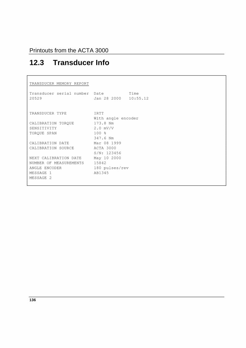
Printouts from the ACTA 3000
136
12.3 Transducer Info
TRANSDUCER MEMORY REPORT Transducer serial number Date Time 20529 Jan 28 2000 10:55.12 TRANSDUCER TYPE IRTT With angle encoder CALIBRATION TORQUE 173.8 Nm SENSITIVITY 2.0 mV/V TORQUE SPAN 100 % 347.6 Nm CALIBRATION DATE Mar 08 1999 CALIBRATION SOURCE ACTA 3000 S/N: 123456 NEXT CALIBRATION DATE May 10 2000 NUMBER OF MEASUREMENTS 15842 ANGLE ENCODER 180 pulses/rev MESSAGE 1 AB1345 MESSAGE 2
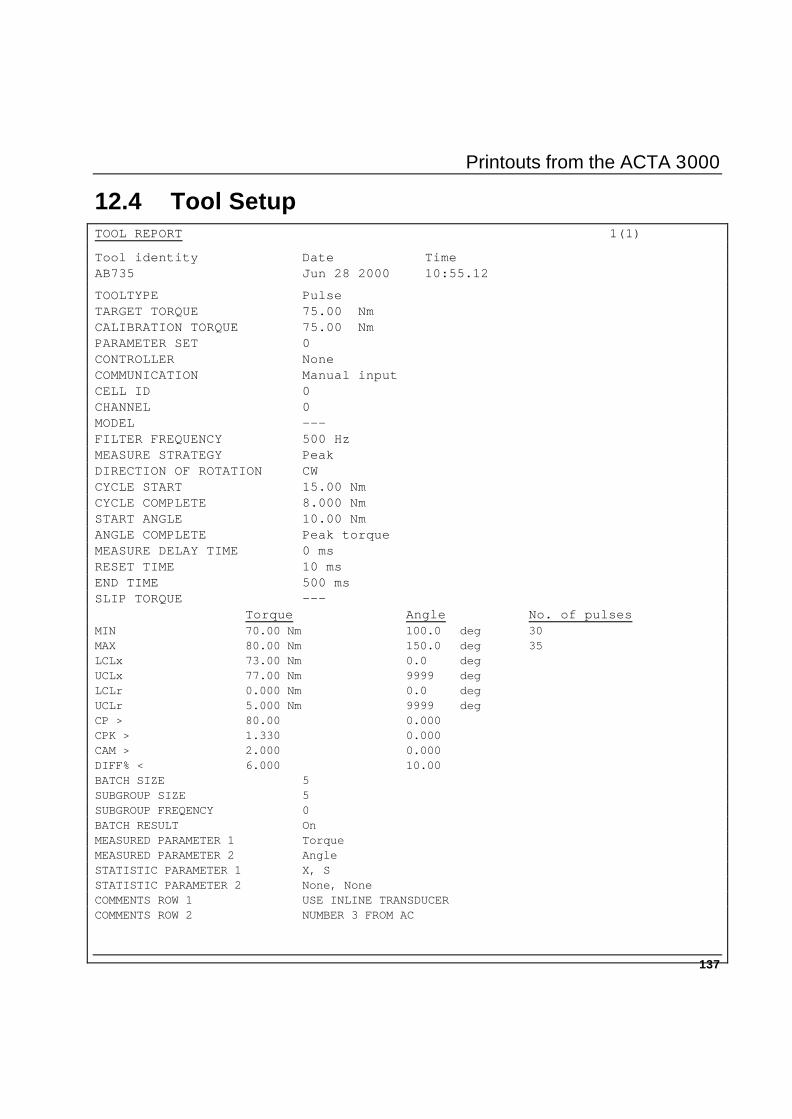
Printouts from the ACTA 3000
137
12.4 Tool Setup TOOL REPORT 1(1)
Tool identity Date Time AB735 Jun 28 2000 10:55.12
TOOLTYPE Pulse TARGET TORQUE 75.00 Nm CALIBRATION TORQUE 75.00 Nm PARAMETER SET 0 CONTROLLER None COMMUNICATION Manual input CELL ID 0 CHANNEL 0 MODEL --- FILTER FREQUENCY 500 Hz MEASURE STRATEGY Peak DIRECTION OF ROTATION CW CYCLE START 15.00 Nm CYCLE COMPLETE 8.000 Nm START ANGLE 10.00 Nm ANGLE COMPLETE Peak torque MEASURE DELAY TIME 0 ms RESET TIME 10 ms END TIME 500 ms SLIP TORQUE --- Torque Angle No. of pulses MIN 70.00 Nm 100.0 deg 30 MAX 80.00 Nm 150.0 deg 35 LCLx 73.00 Nm 0.0 deg UCLx 77.00 Nm 9999 deg LCLr 0.000 Nm 0.0 deg UCLr 5.000 Nm 9999 deg CP > 80.00 0.000 CPK > 1.330 0.000 CAM > 2.000 0.000 DIFF% < 6.000 10.00 BATCH SIZE 5 SUBGROUP SIZE 5 SUBGROUP FREQENCY 0 BATCH RESULT On MEASURED PARAMETER 1 Torque MEASURED PARAMETER 2 Angle STATISTIC PARAMETER 1 X, S STATISTIC PARAMETER 2 None, None COMMENTS ROW 1 USE INLINE TRANSDUCER COMMENTS ROW 2 NUMBER 3 FROM AC
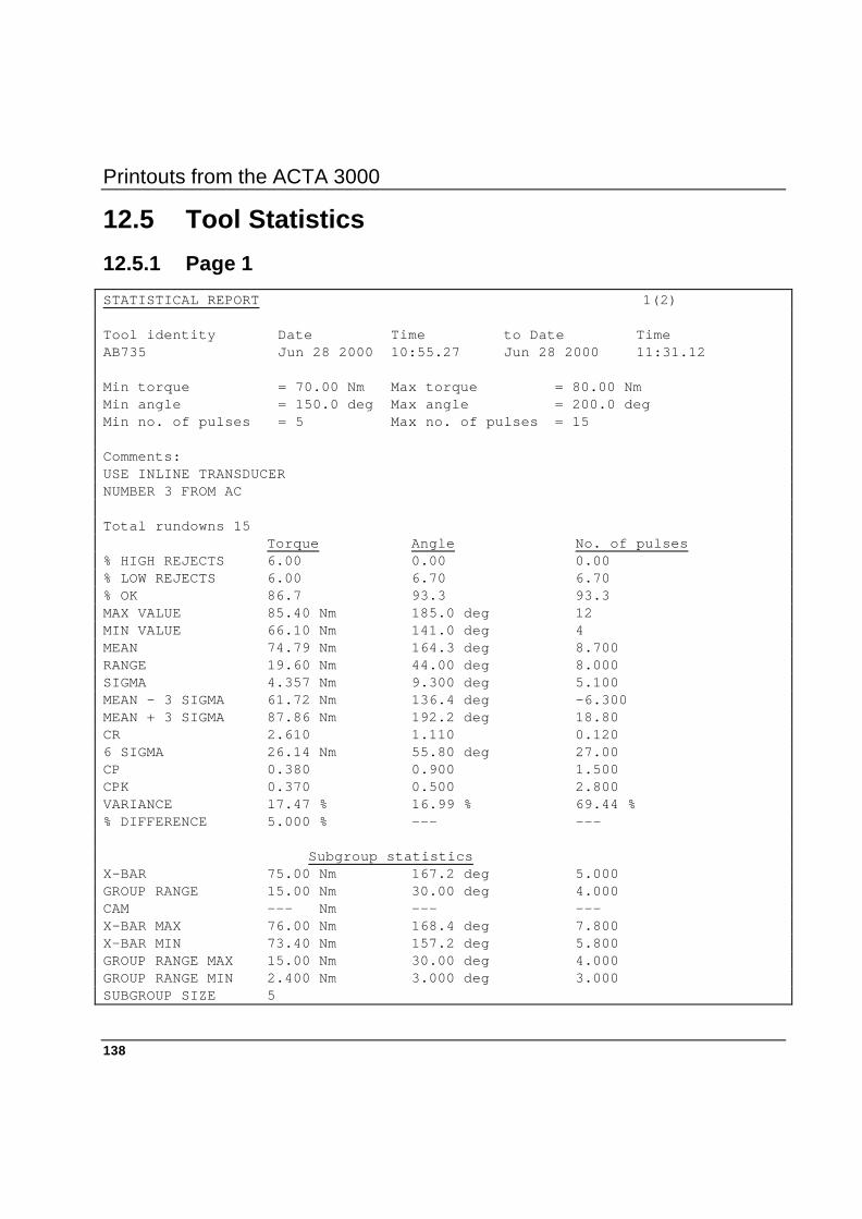
Printouts from the ACTA 3000
138
12.5 Tool Statistics
12.5.1 Page 1
STATISTICAL REPORT 1(2) Tool identity Date Time to Date Time AB735 Jun 28 2000 10:55.27 Jun 28 2000 11:31.12 Min torque = 70.00 Nm Max torque = 80.00 Nm Min angle = 150.0 deg Max angle = 200.0 deg Min no. of pulses = 5 Max no. of pulses = 15 Comments: USE INLINE TRANSDUCER NUMBER 3 FROM AC Total rundowns 15 Torque Angle No. of pulses % HIGH REJECTS 6.00 0.00 0.00 % LOW REJECTS 6.00 6.70 6.70 % OK 86.7 93.3 93.3 MAX VALUE 85.40 Nm 185.0 deg 12 MIN VALUE 66.10 Nm 141.0 deg 4 MEAN 74.79 Nm 164.3 deg 8.700 RANGE 19.60 Nm 44.00 deg 8.000 SIGMA 4.357 Nm 9.300 deg 5.100 MEAN - 3 SIGMA 61.72 Nm 136.4 deg -6.300 MEAN + 3 SIGMA 87.86 Nm 192.2 deg 18.80 CR 2.610 1.110 0.120 6 SIGMA 26.14 Nm 55.80 deg 27.00 CP 0.380 0.900 1.500 CPK 0.370 0.500 2.800 VARIANCE 17.47 % 16.99 % 69.44 % % DIFFERENCE 5.000 % --- --- Subgroup statistics X-BAR 75.00 Nm 167.2 deg 5.000 GROUP RANGE 15.00 Nm 30.00 deg 4.000 CAM --- Nm --- --- X-BAR MAX 76.00 Nm 168.4 deg 7.800 X-BAR MIN 73.40 Nm 157.2 deg 5.800 GROUP RANGE MAX 15.00 Nm 30.00 deg 4.000 GROUP RANGE MIN 2.400 Nm 3.000 deg 3.000 SUBGROUP SIZE 5
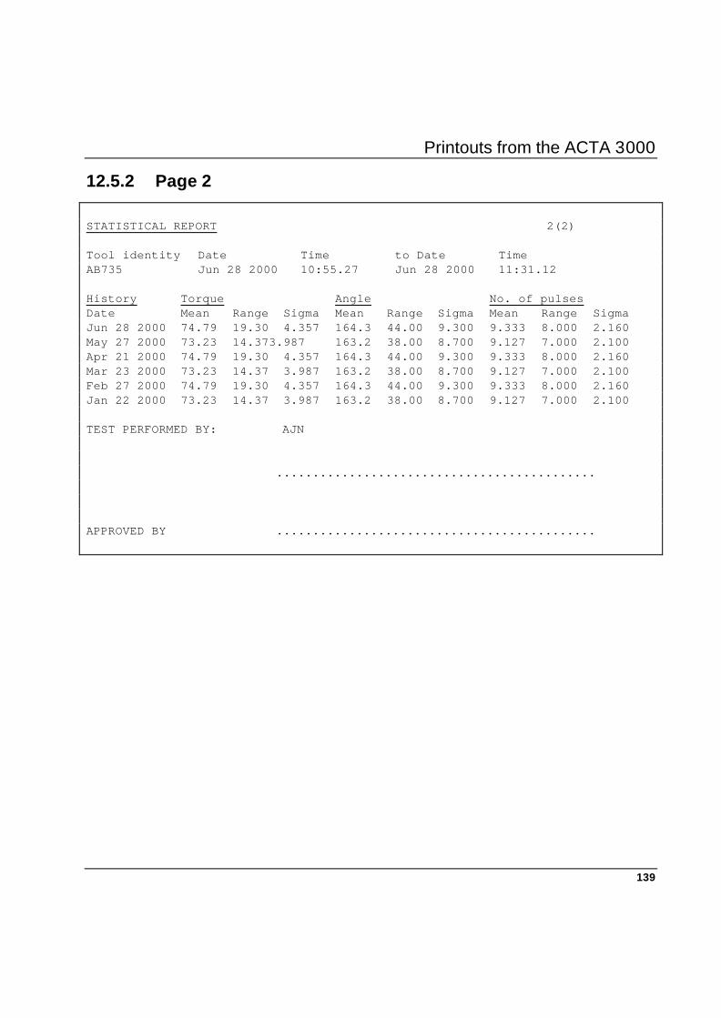
Printouts from the ACTA 3000
139
12.5.2 Page 2
STATISTICAL REPORT 2(2) Tool identity Date Time to Date Time AB735 Jun 28 2000 10:55.27 Jun 28 2000 11:31.12 History Torque Angle No. of pulses Date Mean Range Sigma Mean Range Sigma Mean Range Sigma Jun 28 2000 74.79 19.30 4.357 164.3 44.00 9.300 9.333 8.000 2.160 May 27 2000 73.23 14.373.987 163.2 38.00 8.700 9.127 7.000 2.100 Apr 21 2000 74.79 19.30 4.357 164.3 44.00 9.300 9.333 8.000 2.160 Mar 23 2000 73.23 14.37 3.987 163.2 38.00 8.700 9.127 7.000 2.100 Feb 27 2000 74.79 19.30 4.357 164.3 44.00 9.300 9.333 8.000 2.160 Jan 22 2000 73.23 14.37 3.987 163.2 38.00 8.700 9.127 7.000 2.100 TEST PERFORMED BY: AJN ............................................ APPROVED BY ............................................

Printouts from the ACTA 3000
140
12.6 All Tool Rundowns
See the previous report for one tool.
12.7 All Tool Set-ups
See the previous report for one tool.
12.8 All Tool Statistics
See the previous report for one tool.
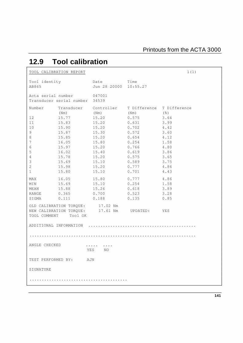
Printouts from the ACTA 3000
141
12.9 Tool calibration
TOOL CALIBRATION REPORT 1(1) Tool identity Date Time AB865 Jun 28 20000 10:55.27 Acta serial number 047001 Transducer serial number 34539
Number Transducer Controller T Difference T Difference (Nm) (Nm) (Nm) (%) 12 15.77 15.20 0.575 3.64 11 15.83 15.20 0.631 3.99 10 15.90 15.20 0.702 4.42 9 15.87 15.30 0.572 3.60 8 15.85 15.20 0.654 4.12 7 16.05 15.80 0.254 1.58 6 15.97 15.20 0.766 4.80 5 16.02 15.40 0.619 3.86 4 15.78 15.20 0.575 3.65 3 15.69 15.10 0.589 3.75 2 15.98 15.20 0.777 4.86 1 15.80 15.10 0.701 4.43
MAX 16.05 15.80 0.777 4.86 MIN 15.69 15.10 0.254 1.58 MEAN 15.88 15.26 0.618 3.89 RANGE 0.365 0.700 0.523 3.28 SIGMA 0.111 0.188 0.135 0.85
OLD CALIBRATION TORQUE: 17.02 Nm NEW CALIBRATION TORQUE: 17.61 Nm UPDATED: YES TOOL COMMENT Tool OK ADDITIONAL INFORMATION ............................................ .................................................................... ANGLE CHECKED ..... .... YES NO TEST PERFORMED BY: AJN SIGNATURE ........................................
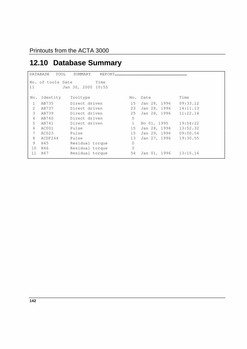
Printouts from the ACTA 3000
142
12.10 Database Summary DATABASE TOOL SUMMARY REPORT……………………………………………………………………………
No. of tools Date Time 11 Jan 30, 2000 10:55
No. Identity Tooltype No. Date Time 1 AB735 Direct driven 15 Jan 28, 1996 09:33.12 2 AB737 Direct driven 23 Jan 28, 1996 14:11.13 3 AB739 Direct driven 25 Jan 28, 1996 11:22.14 4 AB740 Direct driven 0 5 AB741 Direct driven 1 No 01, 1995 19:54:22 6 AC001 Pulse 15 Jan 28, 1996 13:52.32 7 AC023 Pulse 15 Jan 29, 1996 09:00.54 8 ACDF244 Pulse 13 Jan 27, 1996 19:30.55 9 H45 Residual torque 0 10 H46 Residual torque 0 11 H47 Residual torque 54 Jan 01, 1996 13:15.16
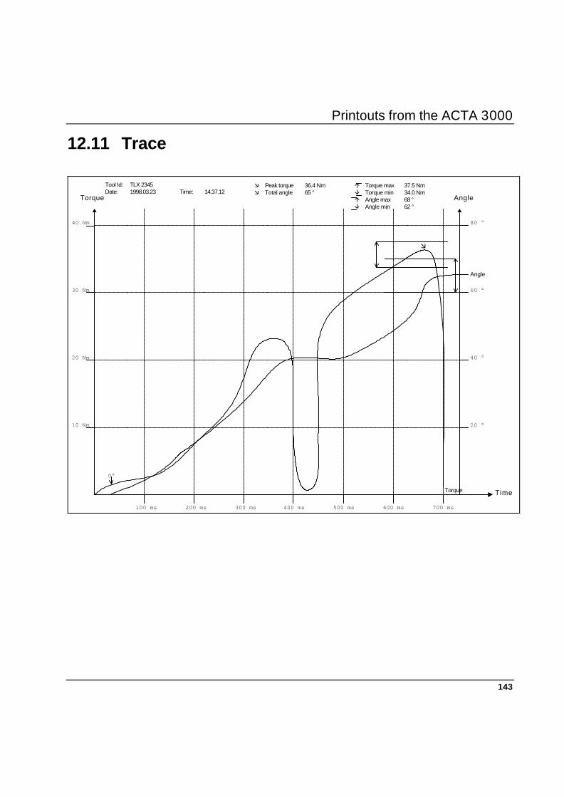
Printouts from the ACTA 3000
143
12.11 Trace
10 Nm
20 Nm
30 Nm
40 Nm
100 ms 200 ms 300 ms 400 ms 500 ms 600 ms 700 ms
Torque
Time
æ Peak torque 36.4 Nm á Torque max 37.5 Nmæ Total angle 65 ° â Torque min 34.0 Nm
á Angle max 68 °â Angle min 62 °
æ
Angle
80 °
60 °
20 °
40 °
Tool Id: TLX 2345Date: 1998.03.23 Time: 14.37.12
0°
Angle
Torque


ToolsTalk ACTA
145
13. ToolsTalk ACTA 13.1 General
With the advent of the ACTA 3000, Atlas Copco Tools introduces ToolsTalk ACTA software which creates a convenient and user-friendly complete quality management tool
ToolsTalk ACTA works with ACTA 3000 Quality Control and Advanced Analysis. It utilises a Windows-like interface and is compatible with Windows 95, 98, 2000 and NT.
Imagine having all your tools, your tightening operation database and supplier database organised all in one place. No more bookcases full of folders with tool data, tightening data, tool service and maintenance data. No more manual tightening data recording in books or several different computer programs.
The ToolsTalk ACTA software can provide all this and more. Use the ACTA 3000 with ToolsTalk ACTA software and you have a complete quality management tool at your service or your complete ISO 9000 under one icon in your PC:
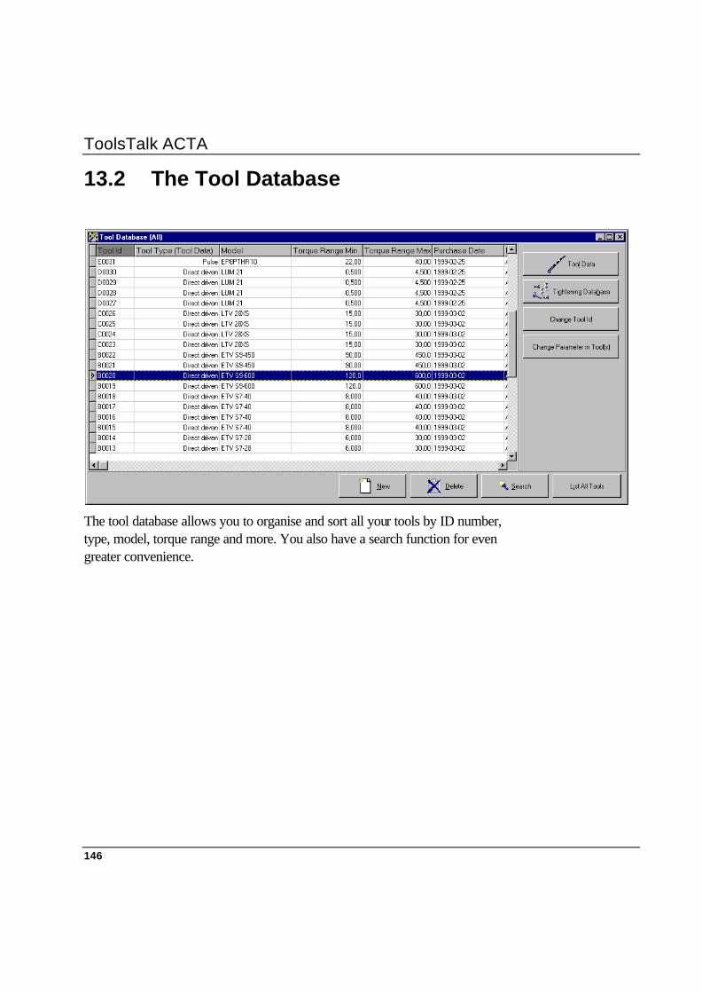
ToolsTalk ACTA
146
13.2 The Tool Database
The tool database allows you to organise and sort all your tools by ID number, type, model, torque range and more. You also have a search function for even greater convenience.

ToolsTalk ACTA
147
13.3 The Supplier Database
Keep track of all your suppliers. In the supplier database you can enter the names of your contacts, companies, phone and fax numbers and e-mail addresses. You no longer need to keep track of all those business cards or keep updating your Rolodex. Everything is in one place.
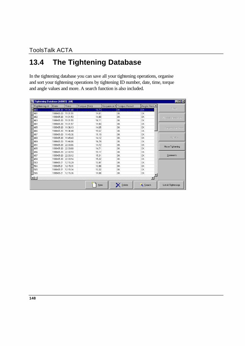
ToolsTalk ACTA
148
13.4 The Tightening Database
In the tightening database you can save all your tightening operations, organise and sort your tightening operations by tightening ID number, date, time, torque and angle values and more. A search function is also included.
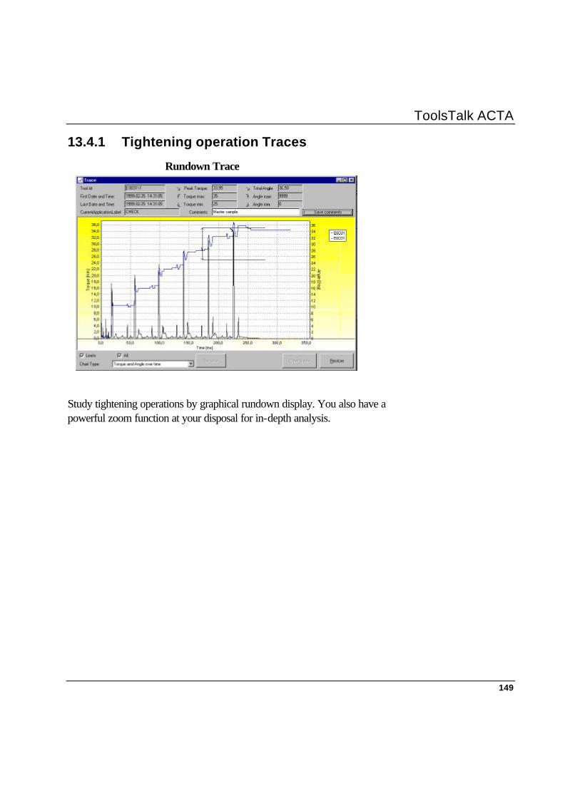
ToolsTalk ACTA
149
13.4.1 Tightening operation Traces
Rundown Trace
Study tightening operations by graphical rundown display. You also have a powerful zoom function at your disposal for in-depth analysis.

ToolsTalk ACTA
150
13.4.2 Tightening Statistics Statistics
ToolsTalk ACTA will keep track of your tightening operation results and can, at any point, calculate and provide you with detailed statistical results of all tightening operations or selected tightening operations performed and saved by any of your tools. Everything just the way you want it.
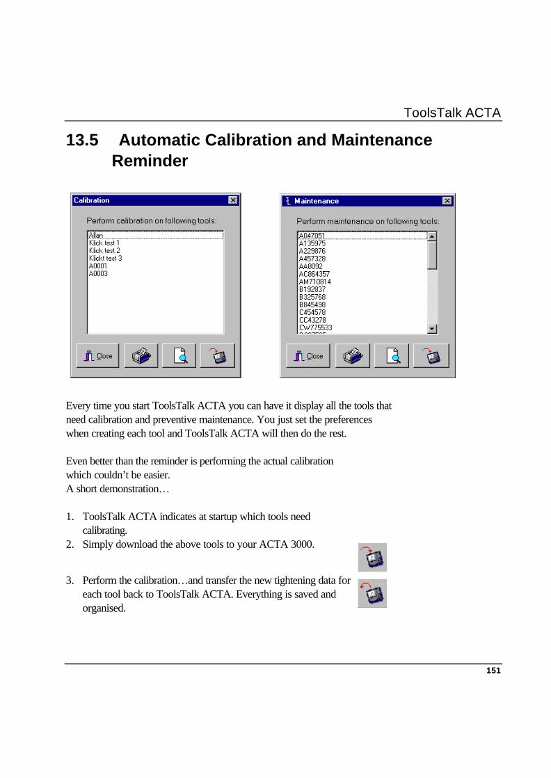
ToolsTalk ACTA
151
13.5 Automatic Calibration and Maintenance Reminder
Every time you start ToolsTalk ACTA you can have it display all the tools that need calibration and preventive maintenance. You just set the preferences when creating each tool and ToolsTalk ACTA will then do the rest. Even better than the reminder is performing the actual calibration which couldn’t be easier. A short demonstration… 1. ToolsTalk ACTA indicates at startup which tools need
calibrating.
2. Simply download the above tools to your ACTA 3000.
3. Perform the calibration…and transfer the new tightening data for
each tool back to ToolsTalk ACTA. Everything is saved and organised.
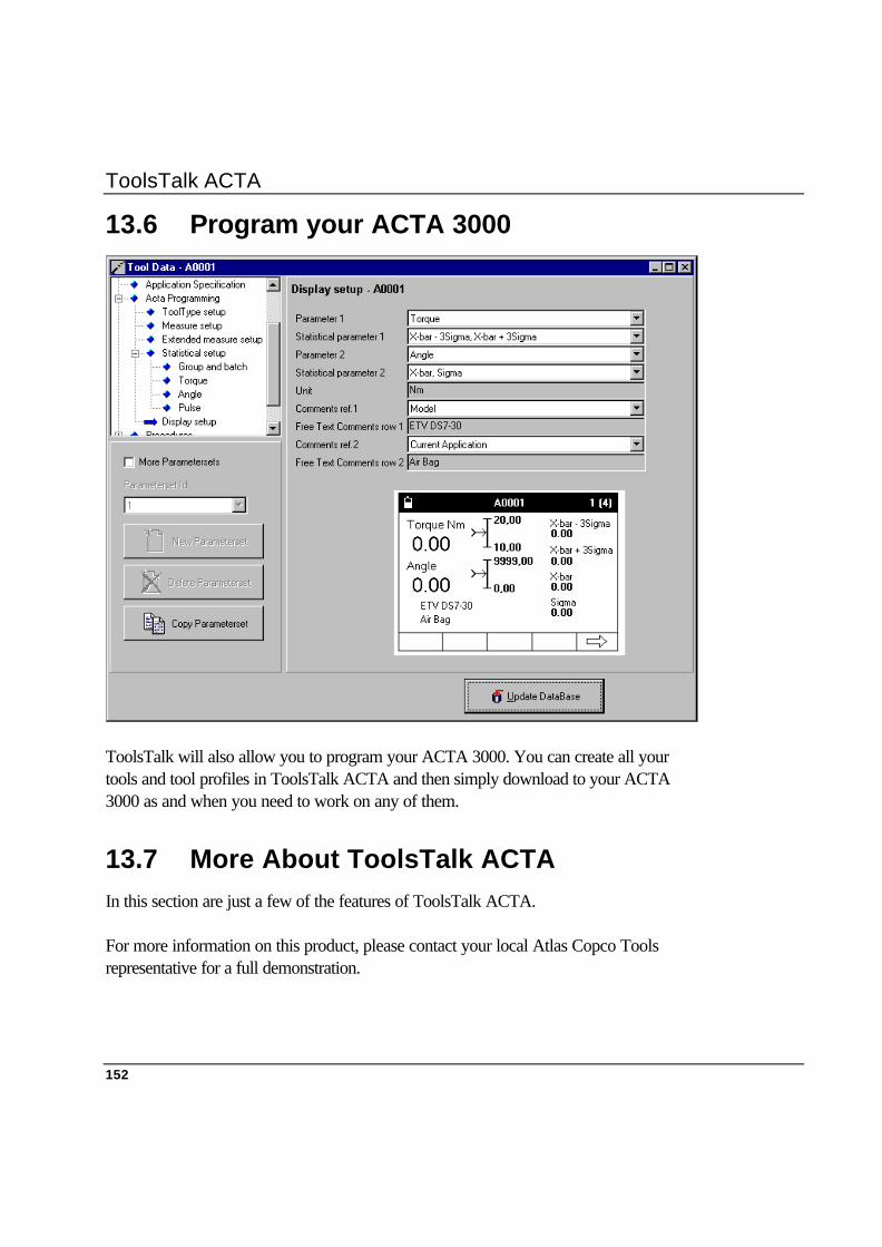
ToolsTalk ACTA
152
13.6 Program your ACTA 3000
ToolsTalk will also allow you to program your ACTA 3000. You can create all your tools and tool profiles in ToolsTalk ACTA and then simply download to your ACTA 3000 as and when you need to work on any of them.
13.7 More About ToolsTalk ACTA In this section are just a few of the features of ToolsTalk ACTA. For more information on this product, please contact your local Atlas Copco Tools representative for a full demonstration.
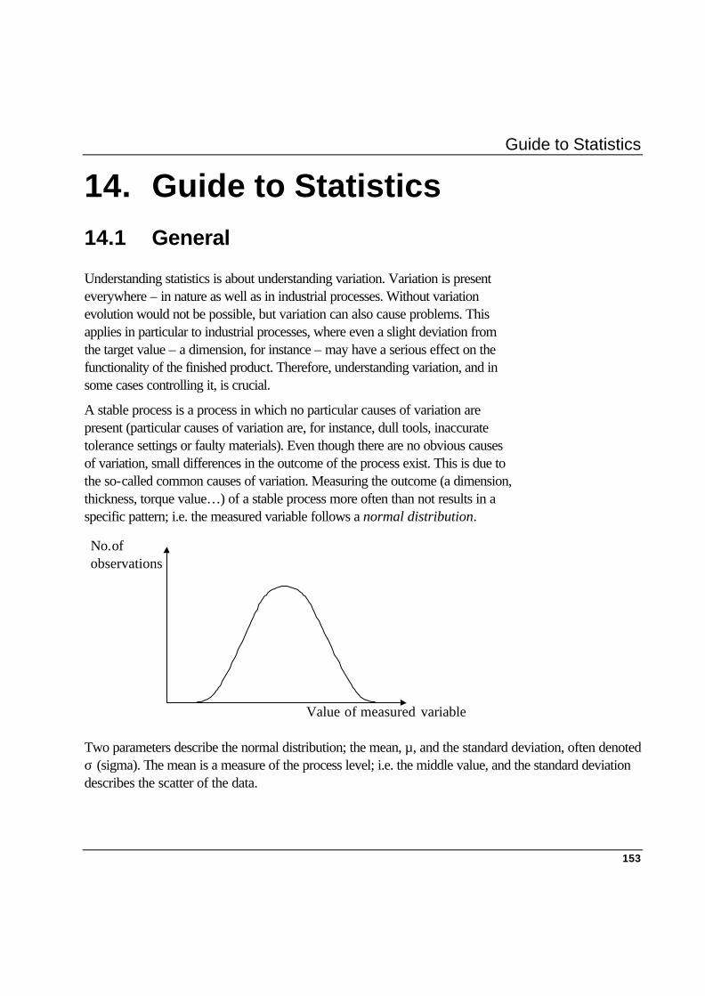
Guide to Statistics
153
14. Guide to Statistics 14.1 General
Understanding statistics is about understanding variation. Variation is present everywhere – in nature as well as in industrial processes. Without variation evolution would not be possible, but variation can also cause problems. This applies in particular to industrial processes, where even a slight deviation from the target value – a dimension, for instance – may have a serious effect on the functionality of the finished product. Therefore, understanding variation, and in some cases controlling it, is crucial.
A stable process is a process in which no particular causes of variation are present (particular causes of variation are, for instance, dull tools, inaccurate tolerance settings or faulty materials). Even though there are no obvious causes of variation, small differences in the outcome of the process exist. This is due to the so-called common causes of variation. Measuring the outcome (a dimension, thickness, torque value…) of a stable process more often than not results in a specific pattern; i.e. the measured variable follows a normal distribution.
Two parameters describe the normal distribution; the mean, µ, and the standard deviation, often denoted σ (sigma). The mean is a measure of the process level; i.e. the middle value, and the standard deviation describes the scatter of the data.
No. of
observations
Value of measured variable

ToolsTalk ACTA
154
Mean Deviation Mean Value and Variation
Normal Distribution with the same Mean Value but different Standard Variations
Normal Distribution with the same Standard Distribution but with different Mean Values.
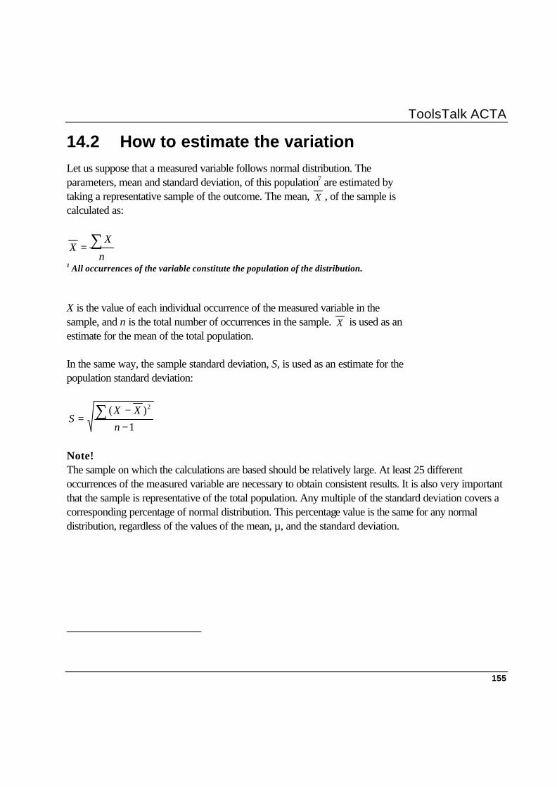
ToolsTalk ACTA
155
14.2 How to estimate the variation Let us suppose that a measured variable follows normal distribution. The parameters, mean and standard deviation, of this population7 are estimated by taking a representative sample of the outcome. The mean, X , of the sample is calculated as:
n
XX ∑=
1 All occurrences of the variable constitute the population of the distribution.
X is the value of each individual occurrence of the measured variable in the sample, and n is the total number of occurrences in the sample. X is used as an estimate for the mean of the total population. In the same way, the sample standard deviation, S, is used as an estimate for the population standard deviation:
1
)( 2
−−
= ∑n
XXS
Note! The sample on which the calculations are based should be relatively large. At least 25 different occurrences of the measured variable are necessary to obtain consistent results. It is also very important that the sample is representative of the total population. Any multiple of the standard deviation covers a corresponding percentage of normal distribution. This percentage value is the same for any normal distribution, regardless of the values of the mean, µ, and the standard deviation.

ToolsTalk ACTA
156
99.994%
68.26%
-σ +σ-2σ +2σ
95.44%
99.73%
-3σ +3σ-4σ +4σ
µ
Sigma and Normal Distribution The sigma interval tells us the percentage of all results found within the sigma limits. The 2-sigma interval (±σ) covers 68.26% of the distribution, 4-sigma (±2σ) covers 95,44% and so on. See the diagram above. This means that, for example, if you perform 1000 tightening operations, 997 of them will be within the 3-sigma limits. This is valid for any normal distribution. The most frequently occurring multiple in the industry is the 6-sigma multiple (±3σ), which is used in statistical process control and when performing capability studies.
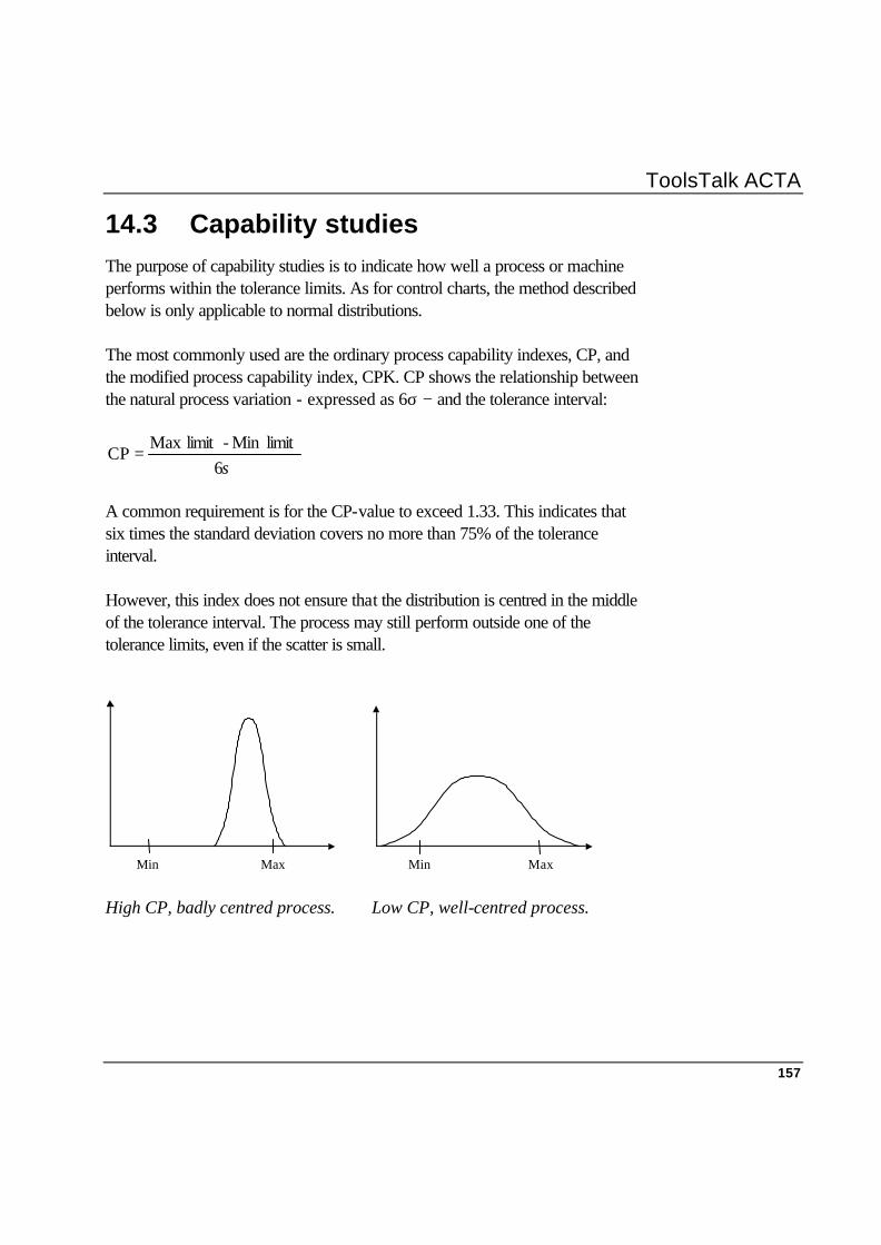
ToolsTalk ACTA
157
14.3 Capability studies The purpose of capability studies is to indicate how well a process or machine performs within the tolerance limits. As for control charts, the method described below is only applicable to normal distributions. The most commonly used are the ordinary process capability indexes, CP, and the modified process capability index, CPK. CP shows the relationship between the natural process variation - expressed as 6σ − and the tolerance interval:
σ6limitMin -limitMax
CP =
A common requirement is for the CP-value to exceed 1.33. This indicates that six times the standard deviation covers no more than 75% of the tolerance interval. However, this index does not ensure that the distribution is centred in the middle of the tolerance interval. The process may still perform outside one of the tolerance limits, even if the scatter is small.
Min Max Min Max High CP, badly centred process. Low CP, well-centred process.

ToolsTalk ACTA
158
The modified process capability index takes into account both setting and spread of data. CPK is specified as the minimum of:
σ3X-limitMax
σ3limitMin -X
The most common requirement is 1,33. However, some manufacturers require a CPK value of 1.5 or higher.
Min Max Both CP and CPK are high.
14.3.1 Six-Sigma Improvement Program
The Six-Sigma improvement program was first introduced at Motorola. The objective of this program is to obtain a CP of at least 2.0 in all of the company's processes. For a centred process this means that the distance from the mean to the tolerance limits will be at least six sigma.
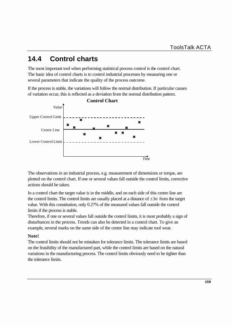
ToolsTalk ACTA
159
14.4 Control charts The most important tool when performing statistical process control is the control chart. The basic idea of control charts is to control industrial processes by measuring one or several parameters that indicate the quality of the process outcome.
If the process is stable, the variations will follow the normal distribution. If particular causes of variation occur, this is reflected as a deviation from the normal distribution pattern.
Upper Control Limit
Lower Control Limit
Centre Line
Control Chart
6 6
6
6 6
6
6
6 6 6
6
6
Time
Value
The observations in an industrial process, e.g. measurement of dimensions or torque, are plotted on the control chart. If one or several values fall outside the control limits, corrective actions should be taken.
In a control chart the target value is in the middle, and on each side of this centre line are the control limits. The control limits are usually placed at a distance of ±3σ from the target value. With this constitution, only 0.27% of the measured values fall outside the control limits if the process is stable. Therefore, if one or several values fall outside the control limits, it is most probably a sign of disturbances in the process. Trends can also be detected in a control chart. To give an example, several marks on the same side of the centre line may indicate tool wear.
Note! The control limits should not be mistaken for tolerance limits. The tolerance limits are based on the feasibility of the manufactured part, while the control limits are based on the natural variations in the manufacturing process. The control limits obviously need to be tighter than the tolerance limits.

ToolsTalk ACTA
160
14.4.1 Using control charts
If the mean value and standard deviation of the variable that is to be controlled are not known, they need to be estimated. The variable is generally measured over a trial period.
As many as 20-25 groups, each group consisting of five separate samples, should be measured. One of the reasons for this is that at least 20 sample groups are necessary to determine whether the process is stable or not.
Calculations to establish the control limits in X-bar chart and R chart respectively are shown below. Most software that is used for statistical process control automatically calculates these values. For further information, please contact your local Atlas Copco representative.
Once the control limits have been established, the control chart can be put into use. The variable is measured at regular intervals and the readings are plotted on the chart. It is usually recommended that sample groups of five separate observations be measured at each interval.
There are different types of control charts. Two of the most common are the X-bar chart and the R chart. Through the X-bar chart the mean, i.e. the level of the process, is controlled. The R chart, where R signifies range, is a means of controlling the process variation.
ToolsTalk ACTA
161
14.4.2 X-bar charts
In an X-bar chart the mean of the measured variable is controlled, and not the value of the variable itself. It is very important to distinguish between the individual observations in one sample group and the mean of the observations. Only the latter is of significance in an X-bar chart.
The centre line in an X-bar chart is the mean of the process outcome. In practice, this is often estimated as the mean of the group means during a trial period. It is denoted:
X (the mean of the means). The control limits are supposed to be at a distance of three standard deviations from the centre line. The standard deviation for the mean of X is expressed as n/σ , where σ stands for the standard deviation of X, and n is the number of observations in each sample group (at least five).
If the standard deviation of X is unknown it can be estimated during the trial period, as described below.
Calculate the range in each sample group, i.e. the difference between the highest and lowest values. The mean, R , of the various group ranges from the sample groups (at least 20-25) is then calculated, and divided by the constant d2. This constant depends on the group size and may be found in manuals of statistical process control. R /d2 is an estimate of the standard deviation of X. Thus, the control limits in the X-bar diagram are:
Upper Control Limit, UCL = )/(3 2 ndRX +
Lower Control Limit, LCL = )/(3 2 ndRX −
In some cases )/(3 2 nd is replaced by a constant, A2, to simplify the calculations:
UCL = RAX 2+
LCL = RAX 2−
ToolsTalk ACTA
162
From the calculations it is clear that the standard deviation of the mean is smaller than the standard deviation of the variable itself. Therefore individual observations may fall outside the control limits. Important Control limits and Tolerance limits are not the same. Control limits are used in SPC. Tolerance limits indicate the minimum and maximum permitted values for a certain application. For a process that is under control, the Control limits are situated within the Tolerance limits.
Individual observations that fall outside the control limits of an X-bar chart do not indicate a problem. If mean points fall outside the control limits, corrective action should be taken.
14.4.3 R charts
The R chart, Range chart, is used for control of the process variation. The centre line is R , and the control limits are calculated as: UCL = D4* R
LCL = D3* R
D4 and D3 depend on the sample group size, and may be found in manuals of statistical process control. D3, and consequently the lower control limit, is 0 for sample groups of six or less.
R charts are useful when the process level remains stable, while the variation changes. Such a change may be difficult to detect in an X-bar chart.
There are numerous ways of establishing the centre line and control limits in control charts. For more information, please contact your local Atlas Copco representative.
Technical Specifications
163
15. Technical Specifications 15.1 Dimensions and Weights Dimensions: Depth: 285mm
Width: 260mm
Height: 77mm
Weight: 1.15 kg (including the battery)
15.2 Electrical Operating voltage: 115 or 230 V AC 50/60 Hz
15.3 Battery
Charge time:
Initial charge 12 hours
Operating 3 hours (approx.)
Operating time:
Normal use 3.5 hours (approx.)
15.3.1 Charging
The battery is charged by connecting an AC power supply to the ACTA 3000.
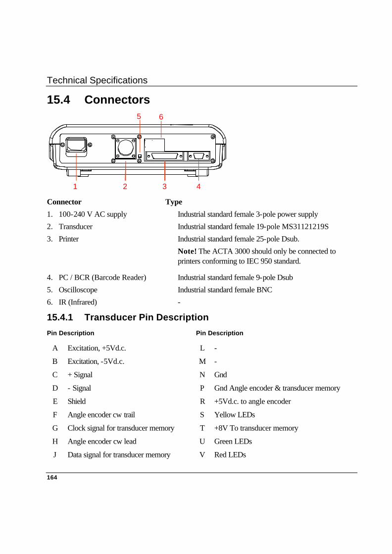
Technical Specifications
164
15.4 Connectors
1 2 3 4
5 6
Connector Type
1. 100-240 V AC supply Industrial standard female 3-pole power supply
2. Transducer Industrial standard female 19-pole MS31121219S
3. Printer Industrial standard female 25-pole Dsub.
Note! The ACTA 3000 should only be connected to printers conforming to IEC 950 standard.
4. PC / BCR (Barcode Reader) Industrial standard female 9-pole Dsub
5. Oscilloscope Industrial standard female BNC
6. IR (Infrared) -
15.4.1 Transducer Pin Description
Pin Description Pin Description
A Excitation, +5Vd.c. L -
B Excitation, -5Vd.c. M -
C + Signal N Gnd
D - Signal P Gnd Angle encoder & transducer memory
E Shield R +5Vd.c. to angle encoder
F Angle encoder cw trail S Yellow LEDs
G Clock signal for transducer memory T +8V To transducer memory
H Angle encoder cw lead U Green LEDs
J Data signal for transducer memory V Red LEDs

Technical Specifications
165
15.5 Barcode Reader
A Barcode Reader (BCR) is used to select tools in the database or set the sequence number.
If a tool message from the BCR equates to a Tool ID in the database, ACTA selects that tool.
Message layout tool ID:
STX ? ? Tool ID ETX
A sequence number message from the BCR sets the sequence number to the code starting position “Barcode position” with the length “Barcode length”. The “Barcode position” and “Barcode length” are configuration parameters. Use the “Configuration” menu to set these parameters.
Message layout sequence number:
STX Sequence no. ETX
Barcode. The set-up for the reader is:
Baud rate 9600
Parity None
# of stopbits 1
# of databits 8
Flow control None
Stop character STX .... ETX
ACK / NAK On
Xon/Xoff Off
RTS/CTS Off

Technical Specifications
166
15.6 Default Setups
15.6.1 New ACTA 3000
Config.
Torque unit Nm
Pulse unit Number of
Language English
Backlight On
Buzzer Off
Date/time Current
Routing Off
New sequence no. Off
Printer protocol PCL3
Paper size A4
Colour Off
Baud rate 38400
Flow control Xon/Xoff
User ----
Torque value Four digits
Barcode position 1
Barcode length 8
Non-Atlas Copco Transducer
Sensitivity 0.59 mV/V
Calibration torque 75 Nm
Comment
Angle encoder 0
Serial number 0
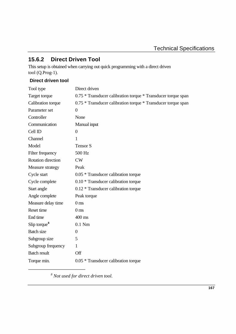
Technical Specifications
167
15.6.2 Direct Driven Tool This setup is obtained when carrying out quick programming with a direct driven tool (Q.Prog-1).
Direct driven tool
Tool type Direct driven Target torque 0.75 * Transducer calibration torque * Transducer torque span Calibration torque 0.75 * Transducer calibration torque * Transducer torque span Parameter set 0 Controller None Communication Manual input Cell ID 0 Channel 1 Model Tensor S Filter frequency 500 Hz Rotation direction CW Measure strategy Peak Cycle start 0.05 * Transducer calibration torque Cycle complete 0.10 * Transducer calibration torque Start angle 0.12 * Transducer calibration torque Angle complete Peak torque Measure delay time 0 ms Reset time 0 ms End time 400 ms Slip torque8 0.1 Nm Batch size 0 Subgroup size 5 Subgroup frequency 1 Batch result Off
Torque min. 0.05 * Transducer calibration torque
8 Not used for direct driven tool.

Technical Specifications
168
Direct driven tool
Torque max Transducer calibration torque * Transducer torque span Torque LCLx -9999.0 Torque UCLx 9999.0 Torque LCLr 0.0 Torque UCLr 9999.0 Torque CP > 0.0 Torque CPK > 0.0 Torque CAM > 0.0 Torque diff % < 9999.0 Angle min. 0.0 Angle max. 9999.0 Angle LCLx -9999.0 Angle UCLx 9999.0 Angle LCLr 0.0 Angle UCLr 9999.0 Angle CP > 0.0 Angle CPK > 0.0 Angle CAM > 0.0 Angle diff. % < 9999.0 No. of pulses min. 0 No. of pulses max. 9999 Parameter 1 Torque
Statistical parameter 1 Mean, σ
Torque units Torque units set by Config.
Pulse units Pulse units set by Config.
Parameter 2 None (If transducer has an angle encoder: Angle)
Statistical parameter 2 None (If transducer has an angle encoder: Mean, σ)
Comments row 1
Comments row 2

Technical Specifications
169
15.6.3 Pulse Tool This setup is obtained when carrying out quick programming with a pulse tool (Q.Prog-2).
Pulse
Tool type Pulse Target torque 0.75 * Transducer calibration torque * Transducer torque span Calibration torque 0.75 * Transducer calibration torque * Transducer torque span Parameter set 0 Controller None Communication Manual input Cell ID 0 Channel 1 Model Tensor S Filter frequency 1500 Hz Rotation direction CW Measure strategy Peak Cycle start 0.05 * Transducer calibration torque Cycle complete 0.10 * Transducer calibration torque Start angle 0.12 * Transducer calibration torque Angle complete Peak torque Measure delay time 0 ms Reset time 0 ms End time 400 ms Slip torque9 0.1 Nm Batch size 0 Subgroup size 5 Subgroup frequency 1 Batch result Off Torque min. 0.05 * Transducer calibration torque
9 Not used for pulse tool.
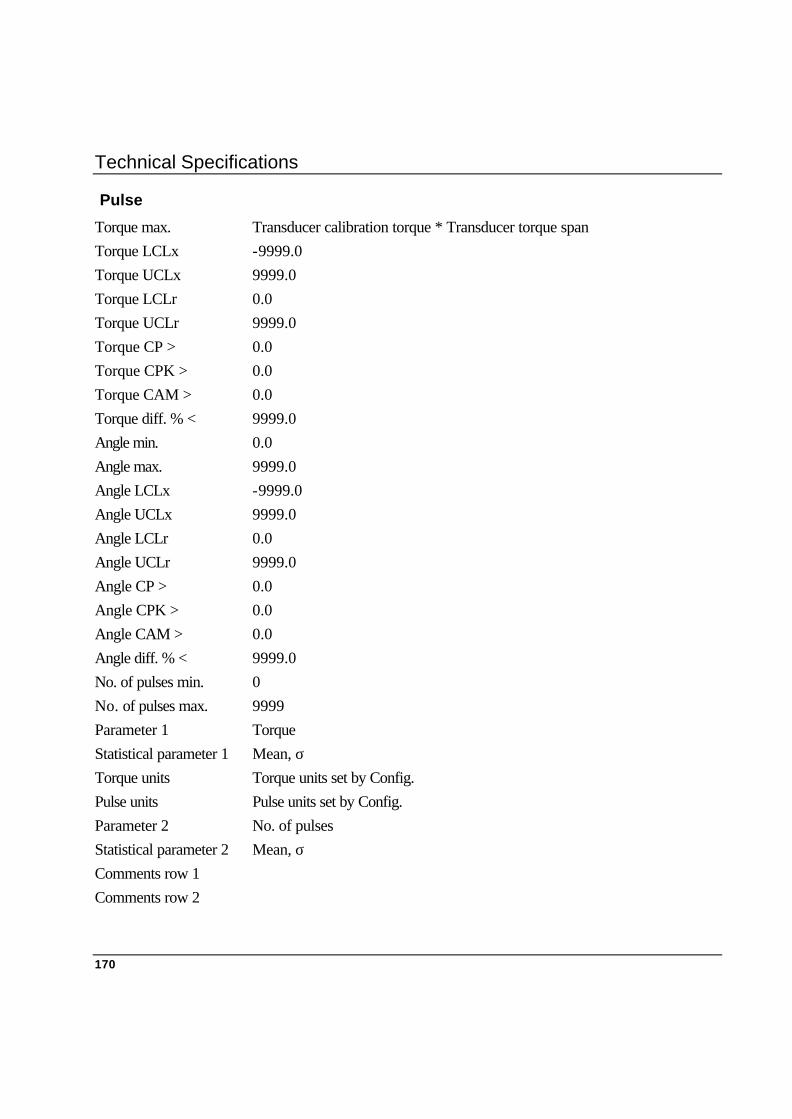
Technical Specifications
170
Pulse
Torque max. Transducer calibration torque * Transducer torque span Torque LCLx -9999.0 Torque UCLx 9999.0 Torque LCLr 0.0 Torque UCLr 9999.0 Torque CP > 0.0 Torque CPK > 0.0 Torque CAM > 0.0 Torque diff. % < 9999.0 Angle min. 0.0 Angle max. 9999.0 Angle LCLx -9999.0 Angle UCLx 9999.0 Angle LCLr 0.0 Angle UCLr 9999.0 Angle CP > 0.0 Angle CPK > 0.0 Angle CAM > 0.0 Angle diff. % < 9999.0 No. of pulses min. 0 No. of pulses max. 9999 Parameter 1 Torque Statistical parameter 1 Mean, σ Torque units Torque units set by Config. Pulse units Pulse units set by Config. Parameter 2 No. of pulses Statistical parameter 2 Mean, σ Comments row 1 Comments row 2

Technical Specifications
171
15.6.4 Wrench This setup is obtained when carrying out quick programming with a wrench (Q.Prog-3).
Wrench Tool type Wrench Target torque 0.75 * Transducer calibration torque * Transducer torque
span Calibration torque 0.75 * Transducer calibration torque * Transducer torque
span Parameter set 0 Controller None Communication Manual input Cell ID 0 Channel 1 Model Tensor S Filter frequency 125 Hz Rotation direction CW Measure strategy Peak or Static installed torque. Cycle start 0.05 * Transducer calibration torque Cycle complete 0.10 * Transducer calibration torque Start angle 0.12 * Transducer calibration torque Angle complete Peak torque Measure delay time 0 ms Reset time 0 ms End time 400 ms Slip torque10 0.1 Nm Batch size 0 Subgroup size 5 Subgroup frequency 1 Batch result Off Torque min. 0.05 * Transducer calibration torque
10 Not used for wrench.
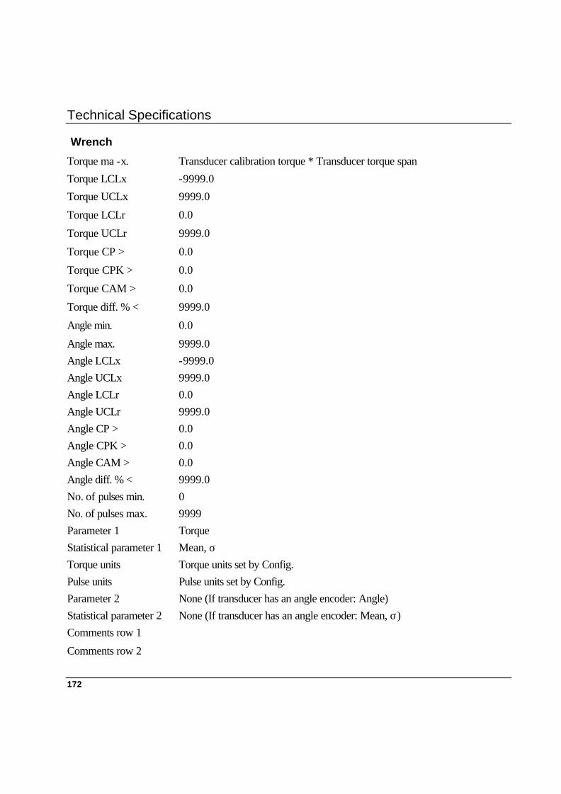
Technical Specifications
172
Wrench
Torque ma -x. Transducer calibration torque * Transducer torque span
Torque LCLx -9999.0
Torque UCLx 9999.0
Torque LCLr 0.0
Torque UCLr 9999.0
Torque CP > 0.0
Torque CPK > 0.0
Torque CAM > 0.0
Torque diff. % < 9999.0
Angle min. 0.0
Angle max. 9999.0 Angle LCLx -9999.0 Angle UCLx 9999.0 Angle LCLr 0.0 Angle UCLr 9999.0 Angle CP > 0.0 Angle CPK > 0.0 Angle CAM > 0.0 Angle diff. % < 9999.0 No. of pulses min. 0 No. of pulses max. 9999 Parameter 1 Torque Statistical parameter 1 Mean, σ Torque units Torque units set by Config. Pulse units Pulse units set by Config. Parameter 2 None (If transducer has an angle encoder: Angle) Statistical parameter 2 None (If transducer has an angle encoder: Mean, σ) Comments row 1
Comments row 2

Technical Specifications
173
15.6.5 Click Wrench
This setup is obtained when carrying out quick programming with a Click Wrench (Q.Prog-4).
Click wrench
Tool type Click wrench
Target torque 0.75 * Transducer calibration torque * Transducer torque span
Calibration torque 0.75 * Transducer calibration torque * Transducer torque span
Parameter set 0
Controller None
Communication Manual input
Cell ID 0
Channel 1
Model Tensor S
Filter frequency 1000 Hz
Rotation direction CW
Measure strategy Break away
Cycle start 0.05 * Transducer calibration torque
Cycle complete 0.10 * Transducer calibration torque
Start angle 0.12 * Transducer calibration torque
Angle complete Peak torque
Measure delay time 0 ms
Reset time 0 ms
End time 400 ms
Slip torque 0.04 * Transducer calibration torque
Batch size 0
Subgroup size 5
Subgroup frequency 1
Batch result Off
Torque min. 0.05 * Transducer calibration torque
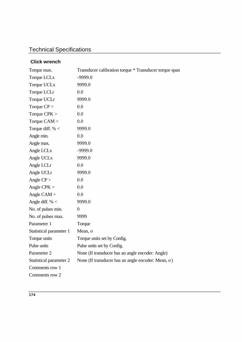
Technical Specifications
174
Click wrench
Torque max. Transducer calibration torque * Transducer torque span Torque LCLx -9999.0 Torque UCLx 9999.0 Torque LCLr 0.0 Torque UCLr 9999.0 Torque CP > 0.0 Torque CPK > 0.0 Torque CAM > 0.0 Torque diff. % < 9999.0 Angle min. 0.0 Angle max. 9999.0 Angle LCLx -9999.0 Angle UCLx 9999.0 Angle LCLr 0.0 Angle UCLr 9999.0 Angle CP > 0.0 Angle CPK > 0.0 Angle CAM > 0.0 Angle diff. % < 9999.0 No. of pulses min. 0 No. of pulses max. 9999 Parameter 1 Torque Statistical parameter 1 Mean, σ Torque units Torque units set by Config. Pulse units Pulse units set by Config. Parameter 2 None (If transducer has an angle encoder: Angle) Statistical parameter 2 None (If transducer has an angle encoder: Mean, σ) Comments row 1 Comments row 2

Technical Specifications
175
15.6.6 Synchronise None controller Tool type Depending on selections Target torque Depending on selections
Calibration torque 0.75 * Transducer calibration torque * Transducer torque span
Parameter set 0
Controller None
Communication Manual input
Cell ID 0
Channel 1
Model None
Filter frequency Depending on selections
Rotation direction CW
Measure strategy Depending on selections
Cycle start 0.05 * Transducer calibration torque
Cycle complete 0.10 * Transducer calibration torque
Start angle 0.12 * Transducer calibration torque
Angle complete Peak torque
Measure delay time 0 ms
Reset time 0 ms
End time 400 ms
Slip torque11 0.1 Nm
Batch size 0
Subgroup size 5
Subgroup frequency 1
Batch result Off
Torque min. 0.05 * Transducer calibration torque
11 Not used for wrench.

Technical Specifications
176
None controller
Torque max. Transducer calibration torque * Transducer torque span Torque LCLx -9999.0 Torque UCLx 9999.0 Torque LCLr 0.0 Torque UCLr 9999.0 Torque CP > 0.0 Torque CPK > 0.0 Torque CAM > 0.0 Torque diff. % < 9999.0 Angle min. 0.0 Angle max. 9999.0 Angle LCLx -9999.0 Angle UCLx 9999.0 Angle LCLr 0.0 Angle UCLr 9999.0 Angle CP > 0.0 Angle CPK > 0.0 Angle CAM > 0.0 Angle diff. % < 9999.0 No. of pulses min. 0 No. of pulses max. 9999 Parameter 1 Torque Statistical parameter 1 Mean, σ Torque units Torque units set by Config. Pulse units Pulse units set by Config. Parameter 2 None (If transducer has an angle encoder: Angle) Statistical parameter 2 None (If transducer has an angle encoder: Mean, σ) Comments row 1 Comments row 2
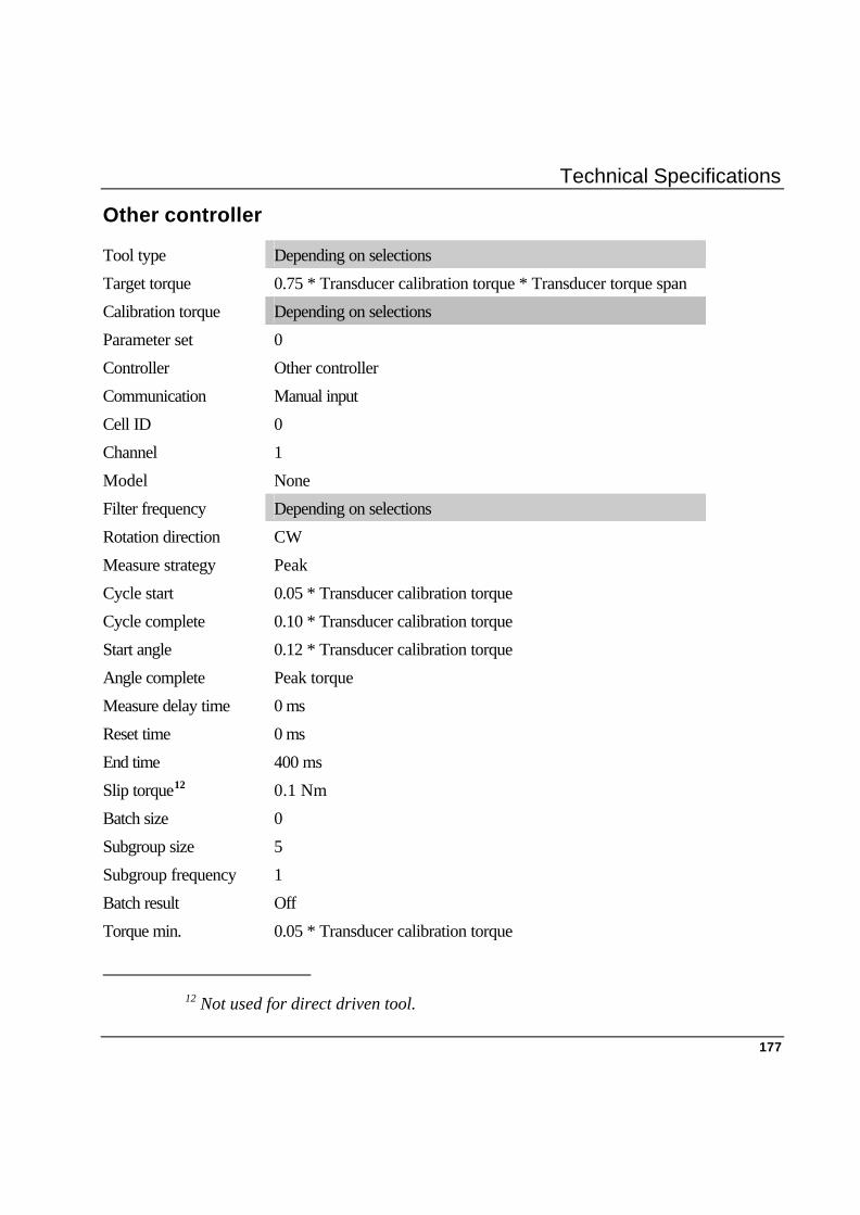
Technical Specifications
177
Other controller
Tool type Depending on selections
Target torque 0.75 * Transducer calibration torque * Transducer torque span
Calibration torque Depending on selections
Parameter set 0
Controller Other controller
Communication Manual input
Cell ID 0
Channel 1
Model None
Filter frequency Depending on selections
Rotation direction CW
Measure strategy Peak
Cycle start 0.05 * Transducer calibration torque
Cycle complete 0.10 * Transducer calibration torque
Start angle 0.12 * Transducer calibration torque
Angle complete Peak torque
Measure delay time 0 ms
Reset time 0 ms
End time 400 ms
Slip torque12 0.1 Nm
Batch size 0
Subgroup size 5
Subgroup frequency 1
Batch result Off
Torque min. 0.05 * Transducer calibration torque
12 Not used for direct driven tool.

Technical Specifications
178
Other controller
Torque max. Transducer calibration torque * Transducer torque span Torque LCLx -9999.0 Torque UCLx 9999.0 Torque LCLr 0.0 Torque UCLr 9999.0 Torque CP > 0.0 Torque CPK > 0.0 Torque CAM > 0.0 Torque diff. % < 9999.0 Angle min. 0.0 Angle max. 9999.0 Angle LCLx -9999.0 Angle UCLx 9999.0 Angle LCLr 0.0 Angle UCLr 9999.0 Angle CP > 0.0 Angle CPK > 0.0 Angle CAM > 0.0 Angle diff. % < 9999.0 No. of pulses min. 0 No. of pulses max. 9999 Parameter 1 Torque Statistical parameter 1 Contr., Diff. Torque units Torque units set by Config. Pulse units Pulse units set by Config. Parameter 2 None (If transducer has an angle encoder: Angle) Statistical parameter 2 None (If transducer has an angle encoder: Contr., Diff.) Comments row 1 Comments row 2

Technical Specifications
179
F2000/PF2000
1. Manual input F2000/PF2000
Tool type Direct driven Target torque 0.75 * Transducer calibration torque * Transducer torque span Calibration torque 0.75 * Transducer calibration torque * Transducer torque span Parameter set 0 Controller F2000/PF2000 Communication Manual input Unit ID 0 Channel 1 Model Tensor S Filter frequency 500 Hz Rotation direction CW Measure strategy Peak Cycle start 0.05 * Transducer calibration torque Cycle complete 0.10 * Transducer calibration torque Start angle 0.12 * Transducer calibration torque Angle complete Peak torque Measure delay time 0 ms Reset time 0 ms End time 400 ms Slip torque13 0.1 Nm Batch size 0 Subgroup size 5 Subgroup frequency 1 Batch result Off Torque min. 0.05 * Transducer calibration torque
13 Not used for direct driven tool.

Technical Specifications
180
F2000/PF2000
Torque max. Transducer calibration torque * Transducer torque span Torque LCLx -9999.0 Torque UCLx 9999.0 Torque LCLr 0.0 Torque UCLr 9999.0 Torque CP > 0.0 Torque CPK > 0.0 Torque CAM > 0.0 Torque diff. % < 9999.0 Angle min. 0.0 Angle max. 9999.0 Angle LCLx -9999.0 Angle UCLx 9999.0 Angle LCLr 0.0 Angle UCLr 9999.0 Angle CP > 0.0 Angle CPK > 0.0 Angle CAM > 0.0 Angle diff. % < 9999.0 No. of pulses min. 0 No. of pulses max. 9999 Parameter 1 Torque Statistical parameter 1 Contr., Diff. Torque units Torque units set by Config. Pulse units Pulse units set by Config. Parameter 2 None (If transducer has an angle encoder: Angle) Statistical parameter 2 None (If transducer has an angle encoder: Contr., Diff.) Comments row 1 Comments row 2

Technical Specifications
181
2. RS232 F2000/PF2000 Tool type Direct driven Target torque Read from controller Calibration torque Read from controller Parameter set Read from controller Controller F2000/PF2000 Communication RS232 Unit ID Depending on selections Channel 1 Model Tensor S Filter frequency 500 Hz Rotation direction CW Measure strategy Peak Cycle start Read from controller Cycle complete Read from controller Start angle Read from controller Angle complete Read from controller Measure delay time Read from controller Reset time Read from controller End time Read from controller Slip torque14 0.1 Nm Batch size Read from controller Subgroup size Read from controller Subgroup frequency 1 Batch result Read from controller Torque min. Read from controller Torque max. Read from controller Torque LCLx -9999.0 Torque UCLx 9999.0 Torque LCLr 0.0
14 Not used for direct driven tool.
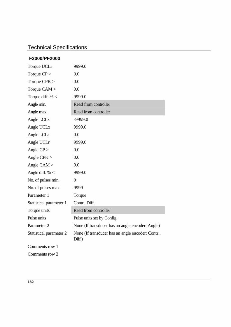
Technical Specifications
182
F2000/PF2000
Torque UCLr 9999.0
Torque CP > 0.0
Torque CPK > 0.0
Torque CAM > 0.0
Torque diff. % < 9999.0
Angle min. Read from controller
Angle max. Read from controller
Angle LCLx -9999.0
Angle UCLx 9999.0
Angle LCLr 0.0
Angle UCLr 9999.0
Angle CP > 0.0
Angle CPK > 0.0
Angle CAM > 0.0
Angle diff. % < 9999.0
No. of pulses min. 0
No. of pulses max. 9999
Parameter 1 Torque
Statistical parameter 1 Contr., Diff.
Torque units Read from controller
Pulse units Pulse units set by Config.
Parameter 2 None (If transducer has an angle encoder: Angle)
Statistical parameter 2 None (If transducer has an angle encoder: Contr., Diff.)
Comments row 1
Comments row 2

Technical Specifications
183
DS
1. Manual input DS
Tool type Direct driven Target torque 0.75 * Transducer calibration torque * Transducer torque span Calibration torque 0.75 * Transducer calibration torque * Transducer torque span Parameter set 0 Controller DS Communication Manual input Cell ID 0 Channel 1 Model Tensor S Filter frequency 500 Hz Rotation direction CW Measure strategy Peak Cycle start 0.05 * Transducer calibration torque Cycle complete 0.10 * Transducer calibration torque Start angle 0.12 * Transducer calibration torque Angle complete Peak torque Measure delay time 0 ms Reset time 0 ms End time 400 ms Slip torque15 0.1 Nm Batch size 0 Subgroup size 5 Subgroup frequency 1 Batch result Off Torque min. 0.05 * Transducer calibration torque
15 Not used for direct driven tool.
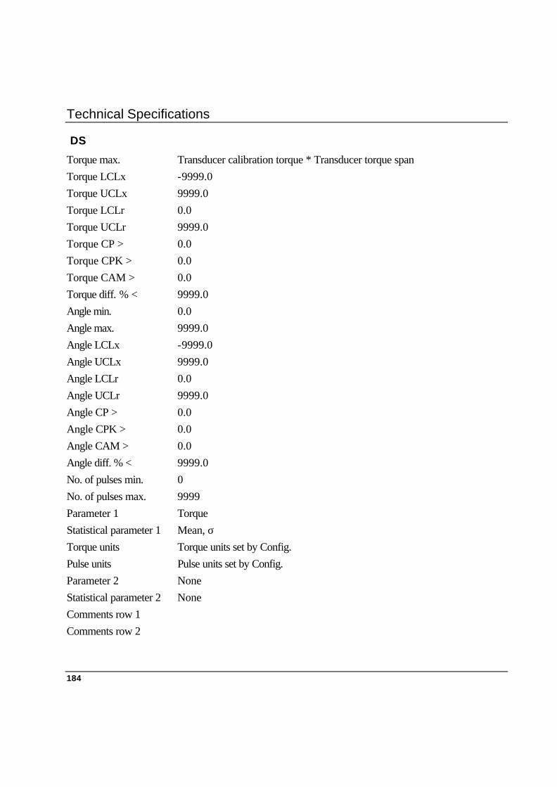
Technical Specifications
184
DS
Torque max. Transducer calibration torque * Transducer torque span Torque LCLx -9999.0 Torque UCLx 9999.0 Torque LCLr 0.0 Torque UCLr 9999.0 Torque CP > 0.0 Torque CPK > 0.0 Torque CAM > 0.0 Torque diff. % < 9999.0 Angle min. 0.0 Angle max. 9999.0 Angle LCLx -9999.0 Angle UCLx 9999.0 Angle LCLr 0.0 Angle UCLr 9999.0 Angle CP > 0.0 Angle CPK > 0.0 Angle CAM > 0.0 Angle diff. % < 9999.0 No. of pulses min. 0 No. of pulses max. 9999 Parameter 1 Torque Statistical parameter 1 Mean, σ Torque units Torque units set by Config. Pulse units Pulse units set by Config. Parameter 2 None Statistical parameter 2 None Comments row 1 Comments row 2

Technical Specifications
185
3. Infrared/RS232 DS
Tool type Direct driven Target torque Read from controller Calibration torque 0.75 * Transducer calibration torque * Transducer torque span Parameter set Read from controller Controller DS Communication Infrared or RS232 Cell ID 0 Channel 1 Model Tensor S Filter frequency 500 Hz Rotation direction CW Measure strategy Peak Cycle start 0.05 * Transducer calibration torque Cycle complete 0.10 * Transducer calibration torque Start angle 0.12 * Transducer calibration torque Angle complete Peak torque Measure delay time 0 ms Reset time 0 ms End time 400 ms Slip torque16 0.1 Nm Batch size 0 Subgroup size 5 Subgroup frequency 1 Batch result Off Torque min. 0.05 * Transducer calibration torque Torque max. Transducer calibration torque * Transducer torque span
16 Not used for direct driven tool.
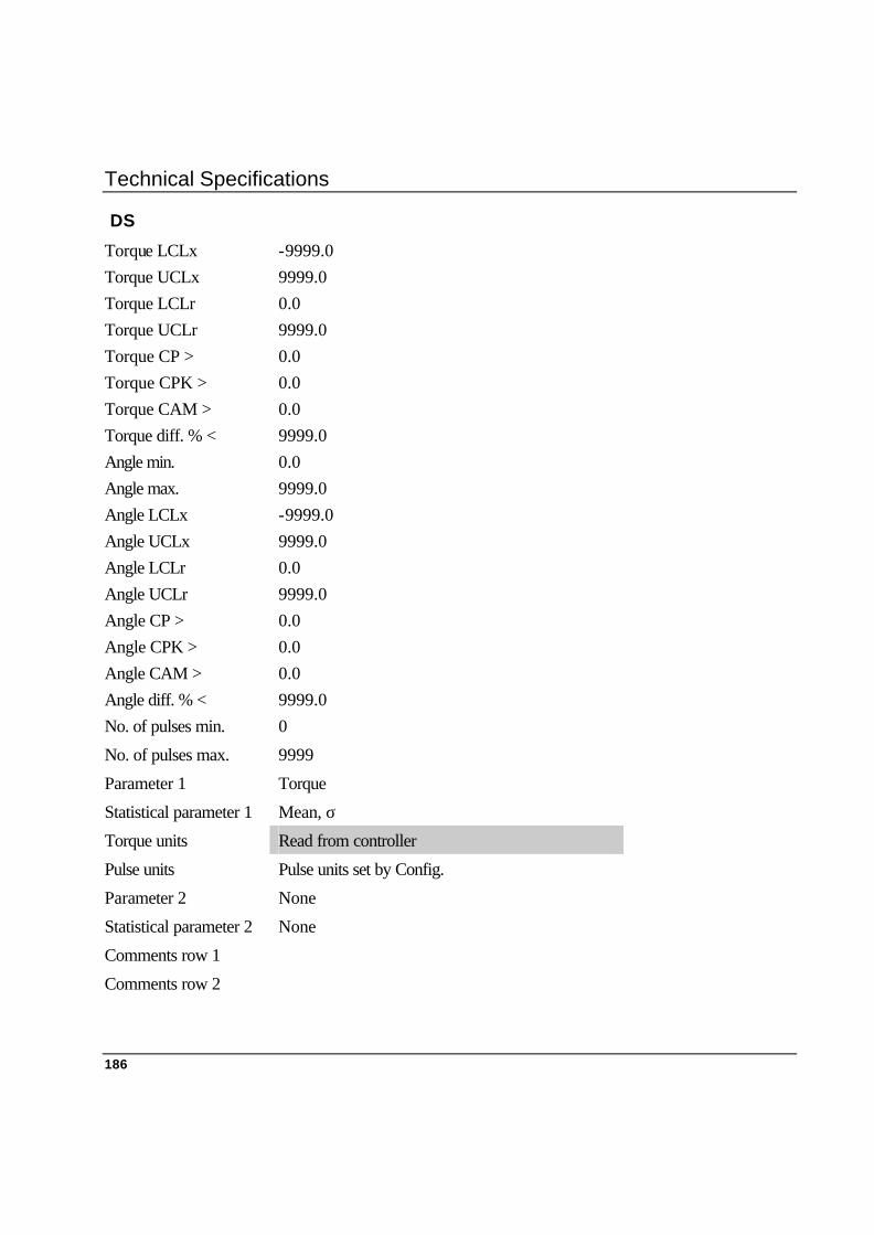
Technical Specifications
186
DS
Torque LCLx -9999.0 Torque UCLx 9999.0 Torque LCLr 0.0 Torque UCLr 9999.0 Torque CP > 0.0 Torque CPK > 0.0 Torque CAM > 0.0 Torque diff. % < 9999.0 Angle min. 0.0 Angle max. 9999.0 Angle LCLx -9999.0 Angle UCLx 9999.0 Angle LCLr 0.0 Angle UCLr 9999.0 Angle CP > 0.0 Angle CPK > 0.0 Angle CAM > 0.0 Angle diff. % < 9999.0 No. of pulses min. 0
No. of pulses max. 9999
Parameter 1 Torque
Statistical parameter 1 Mean, σ
Torque units Read from controller
Pulse units Pulse units set by Config.
Parameter 2 None
Statistical parameter 2 None
Comments row 1
Comments row 2

Technical Specifications
187
PF3000
1. Manual input PF3000
Tool type Direct driven Target torque 0.75 * Transducer calibration torque * Transducer torque span Calibration torque 0.75 * Transducer calibration torque * Transducer torque span Parameter set 0 Controller PF3000 Communication Manual input Cell ID 0 Channel 1 Model Tensor S Filter frequency 500 Hz Rotation direction CW Measure strategy Peak Cycle start 0.05 * Transducer calibration torque Cycle complete 0.10 * Transducer calibration torque Start angle 0.12 * Transducer calibration torque Angle complete Peak torque Measure delay time 0 ms Reset time 0 ms End time 400 ms Slip torque17 0.1 Nm Batch size 0 Subgroup size 5 Subgroup frequency 1 Batch result Off Torque min. 0.05 * Transducer calibration torque
17 Not used for direct driven tool.
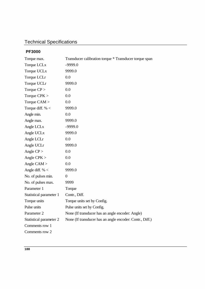
Technical Specifications
188
PF3000
Torque max. Transducer calibration torque * Transducer torque span Torque LCLx -9999.0 Torque UCLx 9999.0 Torque LCLr 0.0 Torque UCLr 9999.0 Torque CP > 0.0 Torque CPK > 0.0 Torque CAM > 0.0 Torque diff. % < 9999.0 Angle min. 0.0 Angle max. 9999.0 Angle LCLx -9999.0 Angle UCLx 9999.0 Angle LCLr 0.0 Angle UCLr 9999.0 Angle CP > 0.0 Angle CPK > 0.0 Angle CAM > 0.0 Angle diff. % < 9999.0 No. of pulses min. 0 No. of pulses max. 9999 Parameter 1 Torque Statistical parameter 1 Contr., Diff. Torque units Torque units set by Config. Pulse units Pulse units set by Config. Parameter 2 None (If transducer has an angle encoder: Angle) Statistical parameter 2 None (If transducer has an angle encoder: Contr., Diff.) Comments row 1 Comments row 2

Technical Specifications
189
2. RS232 PF3000
Tool type Direct driven Target torque Read from controller Calibration torque Read from controller Parameter set Read from controller Controller PF3000 Communication RS232 Cell ID 0 Channel 1 Model Read from controller Filter frequency 500 Hz Rotation direction CW Measure strategy Peak Cycle start Read from controller Cycle complete Read from controller Start angle Read from controller Angle complete Read from controller Measure delay time 0 ms Reset time 0 ms End time Read from controller Slip torque18 0.1 Nm Batch size Read from controller Subgroup size Read from controller Subgroup frequency 1 Batch result Off Torque min. Read from controller Torque max. Read from controller Torque LCLx Read from controller Torque UCLx Read from controller Torque LCLr Read from controller
18 Not used for direct driven tool.
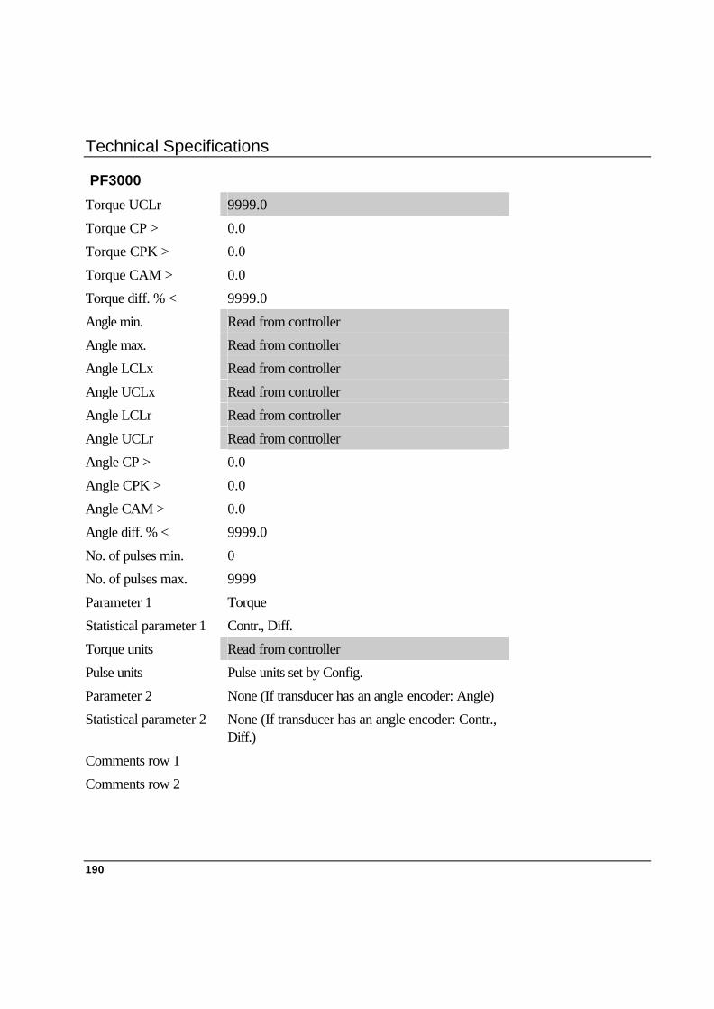
Technical Specifications
190
PF3000
Torque UCLr 9999.0
Torque CP > 0.0
Torque CPK > 0.0
Torque CAM > 0.0
Torque diff. % < 9999.0
Angle min. Read from controller
Angle max. Read from controller
Angle LCLx Read from controller
Angle UCLx Read from controller
Angle LCLr Read from controller
Angle UCLr Read from controller
Angle CP > 0.0
Angle CPK > 0.0
Angle CAM > 0.0
Angle diff. % < 9999.0
No. of pulses min. 0
No. of pulses max. 9999
Parameter 1 Torque
Statistical parameter 1 Contr., Diff.
Torque units Read from controller
Pulse units Pulse units set by Config.
Parameter 2 None (If transducer has an angle encoder: Angle)
Statistical parameter 2 None (If transducer has an angle encoder: Contr., Diff.)
Comments row 1
Comments row 2

Technical Specifications
191
PowerMac
1. Manual input PowerMac
Tool type Direct driven Target torque 0.75 * Transducer calibration torque * Transducer torque span Calibration torque 0.75 * Transducer calibration torque * Transducer torque span Parameter set 0 Controller Power Macs Communication Manual input Cell ID 0 Channel 1 Model Tensor S Filter frequency 500 Hz Rotation direction CW Measure strategy Peak Cycle start 0.05 * Transducer calibration torque Cycle complete 0.10 * Transducer calibration torque Start angle 0.12 * Transducer calibration torque Angle complete Peak torque Measure delay time 0 ms Reset time 0 ms End time 400 ms Slip torque19 0.1 Nm Batch size 0 Subgroup size 5 Subgroup frequency 1 Batch result Off Torque min. 0.05 * Transducer calibration torque
19 Not used for direct driven tool.

Technical Specifications
192
PowerMac
Torque max. Transducer calibration torque * Transducer torque span Torque LCLx -9999.0 Torque UCLx 9999.0 Torque LCLr 0.0 Torque UCLr 9999.0 Torque CP > 0.0 Torque CPK > 0.0 Torque CAM > 0.0 Torque diff. % < 9999.0 Angle min. 0.0 Angle max. 9999.0 Angle LCLx -9999.0 Angle UCLx 9999.0 Angle LCLr 0.0 Angle UCLr 9999.0 Angle CP > 0.0 Angle CPK > 0.0 Angle CAM > 0.0 Angle diff. % < 9999.0 No of pulses min. 0 No of pulses max. 9999 Parameter 1 Torque Statistical parameter 1 Contr., Diff. Torque units Torque units set by Config. Pulse units Pulse units set by Config. Parameter 2 None (If transducer has an angle encoder: Angle) Statistical parameter 2 None (If transducer has an angle encoder: Contr., Diff.) Comments row 1 Comments row 2

Technical Specifications
193
2. RS232 PowerMac
Tool type Direct driven Target torque Read from controller Calibration torque Read from controller Parameter set Read from controller Controller Power Macs Communication RS232 Cell ID 0 Channel 1 Model Tensor S Filter frequency 500 Hz Rotation direction CW Measure strategy Peak Cycle start Read from controller Cycle complete Read from controller Start angle Read from controller Angle complete Read from controller Measure delay time 0 Reset time 0 End time Read from controller Slip torque20 0.1 Nm Batch size Read from controller Subgroup size Read from controller Subgroup frequency 1 Batch result Off Torque min. Read from controller Torque max. Read from controller Torque LCLx Read from controller Torque UCLx Read from controller Torque LCLr Read from controller
20 Not used for direct driven tool.
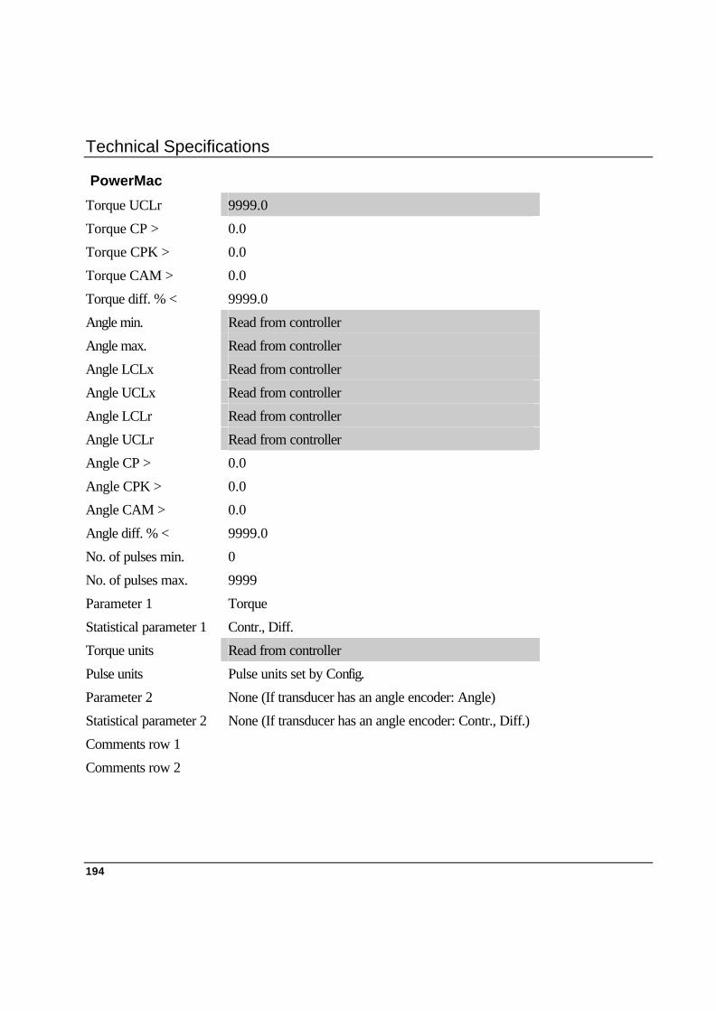
Technical Specifications
194
PowerMac
Torque UCLr 9999.0
Torque CP > 0.0
Torque CPK > 0.0
Torque CAM > 0.0
Torque diff. % < 9999.0
Angle min. Read from controller
Angle max. Read from controller
Angle LCLx Read from controller
Angle UCLx Read from controller
Angle LCLr Read from controller
Angle UCLr Read from controller
Angle CP > 0.0
Angle CPK > 0.0
Angle CAM > 0.0
Angle diff. % < 9999.0
No. of pulses min. 0
No. of pulses max. 9999
Parameter 1 Torque
Statistical parameter 1 Contr., Diff.
Torque units Read from controller
Pulse units Pulse units set by Config.
Parameter 2 None (If transducer has an angle encoder: Angle)
Statistical parameter 2 None (If transducer has an angle encoder: Contr., Diff.)
Comments row 1
Comments row 2
Maintenance
195
16. Maintenance 16.1 Cleaning
Before cleaning your ACTA 3000 always switch it off and disconnect it from the external power supply.
The Acta 3000 should be cleaned with a moist cloth. Use water and a mild soap solution. Wipe dry. Do not use any solutions containing oil or silicone, or other solutions that are harmful to plastics.
16.2 Service The ACTA 3000 does not contain any serviceable items. For service always contact your local Atlas Copco service representative. Never attempt to open the unit.
16.3 Software Upgrade To upgrade the software in your ACTA 3000, please contact your local Atlas Copco service representative.

Accessories, Parts
197
17. Accessories, Parts 17.1 Accessories Ordering No. Description 4222 0527 00 Demo case ACTA 3000
4222 0623 00 ACTA 3000 Leather Work Case
4222 0369 90 ACTA 3000 Charger
4222 0578 90 ACTA 3000 Carrier
4222 0597 82 ACTA 3000 Handle
4145 0963 01 Transducer cable 1m 19 – 19
4145 0963 03 Transducer cable 3m 19 – 19
4145 0963 05 Transducer cable 5m 19 - 19
4145 0965 03 Transducer cable 3m 19 - 4
4145 0966 03 Transducer cable 3m 19 – 6 Knowbar old style
4145 0968 03 Transducer cable 3m 19 – 6 Industrial style
4145 0967 03 Transducer cable 3m 19 – 10 Crane, RS. style
TT ACTA
8092 1136 01 TT ACTA Single user
8092 1136 05 TT ACTA Network 5 users
8092 1136 10 TT ACTA Network 10 users
8092 1136 20 TT ACTA Network 20 users
8092 1136 50 TT ACTA Network 50 users