9. auxiliary systems ap1000 design control document ... · 9. auxiliary systems ap1000 design...
TRANSCRIPT

9. Auxiliary Systems AP1000 Design Control Document
Tier 2 Material 9A-1 Revision 19
APPENDIX 9A
FIRE PROTECTION ANALYSIS
9A.1 Introduction
The AP1000 fire protection analysis is largely based upon the AP600 fire protection analysis that supported the AP600 Design Certification. It evaluates the potential for occurrence of fires within the plant and documents the capabilities of the fire protection system and the capability to safely shut down the plant. The fire protection analysis is an integral part of the process of selecting fire prevention, detection, and suppression methods, and provides a design basis for the fire protection system. The design of the fire protection system is described in subsection 9.5.1.
The purpose of the fire protection analysis is as follows:
• Identify the potential for fires based on the type, quantity, and location of combustible materials
• Determine the consequences of postulated fires
• Provide a basis for decisions on how to prevent, detect, contain, and suppress fires
• Assess fire protection system adequacy
• Confirm the capability to safely shut down the plant following a fire
The fire protection analysis is performed for each fire area using the methodology described in Section 9A.2. This methodology follows the guidance of Branch Technical Position (BTP) CMEB 9.5-1 (Reference 1). The results of the analysis are provided in Section 9A.3.
The fire protection analysis is performed for areas of the plant containing safety-related components and for areas containing systems important to the generation of electricity. It is performed on an area by area basis outside containment and a zone by zone basis inside containment. This approach provides confidence that plant safety is preserved.
9A.2 Fire Protection Analysis Methodology
9A.2.1 Fire Area Description
The plant is divided into fire areas and fire zones as described in subsection 9.5.1.2.1.1. These fire areas/zones and their boundaries are illustrated on Figures 9A-1 through 9A-5.
The analysis for each fire area briefly describes the fire area and associated fire zones, and identifies the principal systems and safety-related components in the fire area. Fire detection and suppression features are listed and the means of smoke control is discussed. The term "smoke" is used throughout this document to imply "smoke and products of combustion".

9. Auxiliary Systems AP1000 Design Control Document
Tier 2 Material 9A-2 Revision 19
This document also uses terminology defined in NFPA 13, such as "light hazard", "ordinary hazard", and "extra hazard". Normally, these terms apply to sprinkler installations and their water supplies only. However, as used herein, the terms apply to the quantity and combustibility of the contents of a given fire area or fire zone irrespective of whether or not sprinklers are present.
9A.2.2 Combustible Material Survey
Each fire area and fire zone is surveyed to determine the type, quantity and distribution of in-situ combustible materials. Where the presence of transient combustibles is anticipated (for example, materials required to support refueling activities or scheduled maintenance) these materials are also identified.
When estimating quantities of electrical cable insulation, cable trays are assumed to have a cable fill of 30 percent of the usable tray depth. Cable enclosed in conduit or in closed metal cabinets is not included in the combustible material survey.
9A.2.3 Fire Severity Categorization
For purposes of evaluating fire barrier adequacy, the expected fire severity for each area/zone is categorized from A (slight) to E (severe) in accordance with Table 7-9E of the NFPA Fire Protection Handbook, 16th edition (Reference 2), based on the type of materials present.
Fire severity category A is used for battery cases, category C is used for electrical cable insulation, and category E is used for combustible liquids. For fire areas containing mixed combustibles, an average category is used. If there are significant concentrations of combustible materials in the area/zone, the category assigned is generally more severe than that used for a uniform distribution.
9A.2.4 Combustible Loading and Equivalent Fire Duration Calculations
Fire barriers, detection and suppression methods are based on several factors, including regulatory guidance, the type of combustibles present, and investment protection considerations. Regulatory guidance takes precedent over the other considerations.
Combustible loading and equivalent fire duration calculations are performed for each fire area and each fire zone. The preliminary calculations provide information used in the selection of fire detection and suppression methods.
Combustible Loading Calculations
The calculation of combustible loading provides an indication of the maximum heat that is released if all the combustibles in a given fire area/zone are consumed.
The potential heat release (expressed in British thermal units, or Btus) for each type of combustible material in the fire area/zone is the product of the quantity of each combustible multiplied by its heat of combustion. The heat of combustion values used for these calculations are listed in Table 9A-1. The maximum heat release for all combustibles in the fire area/zone is found by adding the potential heat release of each combustible material.

9. Auxiliary Systems AP1000 Design Control Document
Tier 2 Material 9A-3 Revision 19
The combustible loading for the fire area/zone is the maximum heat release per square foot (Btus per square foot). It is determined by dividing the maximum heat release for all combustibles in the fire area/zone by the floor area of the fire area or zone.
For fire areas that are not protected based on regulatory guidance and that do not have concentrations of volatile or radioactive combustibles, fire detection and suppression needs are established based on combustible loading, using the following guidelines:
Combustible Loading (Btu/ft2)
Detection Suppression Capability
0 to 8,000
Capability
None Manual
8,000 to 80,000 Yes Manual
Above 80,000 Yes Automatic and Manual In addition, concentrations of combustibles were evaluated, including their proximity to fire barriers.
Equivalent Fire Duration
The duration of a fire in a given fire area or zone is influenced by many factors, including:
• The properties of the material (ease of ignition and rate of heat release)
• The surface area of the combustible material
• The presence of fire retardant coatings
• Ventilation parameters and availability of oxygen
• The degree of separation or the presence of barriers between groups of combustible materials
Fire duration is estimated based on the fire severity category and the equivalent combustible loading. Equivalent combustible loading is defined as the weight per square foot of ordinary combustibles (wood or paper) having a heat of combustion of 8,000 Btu/lb, that releases the same total heat as the combustibles in the fire area/zone. The equivalent combustible loading is calculated by dividing the maximum heat release per square foot by 8,000 Btu/lb. The fire endurance lines of Figure 7-9B of the NFPA Fire Protection Handbook, 16th edition (Reference 2), are used to estimate the fire duration in minutes.
Fire barriers are tested by exposure to a fire whose severity follows a time varying temperature curve known as the standard time-temperature curve (NFPA Fire Protection Handbook, 18th edition [Reference 5], Figure 7-5A.) The estimated fire duration for each fire area is normalized based on the standard time-temperature curve to obtain an equivalent fire duration. This value is compared with the fire resistance of the fire area boundaries. This comparison is used in conjunction with other factors, including those listed above, in making a determination of the adequacy of the fire area boundaries.

9. Auxiliary Systems AP1000 Design Control Document
Tier 2 Material 9A-4 Revision 19
9A.2.5 Fire Protection Adequacy
The adequacy of the fire protection features for a postulated fire in each fire area or fire zone is evaluated. This evaluation includes the following points:
• A review of the AP600 Design Certification and other regulatory guidance
• A review of how the fire is detected and suppressed
• Verification of the adequacy of the fire resistance of the fire area boundaries
• Verification that the ventilation system for the fire area does not contribute to the spread of fire or smoke
• Verification that a fire in a nonsafety-related area does not threaten safety-related areas of the plant
• Verification that, for a fire in an area containing radioactive materials, the capability to minimize and control a potential release of radioactivity is not adversely affected
• A determination of the need for structural steel fireproofing
• A determination of the capability of the drainage systems to handle fire protection water flow.
9A.2.6 Fire Protection System Integrity
For fire areas containing safety-related components, the potential for a credible inadvertent actuation of automatic suppression systems is determined and the consequences are evaluated.
The design of automatic and manual suppression systems is reviewed to verify that there is no potential single impairment which incapacitates both the automatic suppression system and the manual suppression system.
9A.2.7 Safe Shutdown Evaluation
This subsection describes the methodology for evaluation of the effects of postulated fires in each fire area on the ability of the operator to achieve a safe shutdown of the plant. The criteria and assumptions upon which the evaluation is based are described in subsection 9A.2.7.1. The safety-related features of the plant designed to provide the safe shutdown capability are described in subsection 9A.2.7.2.
As indicated in subsection 9.5.1, this evaluation is based upon satisfying the requirements of BTP CMEB 9.5-1. This basis includes using safe shutdown as defined in Section 16.1 in lieu of cold shutdown wherever stated in BTP CMEB 9.5-1. The automatic depressurization system is not used as the method for achieving safe shutdown after a fire and spurious actuation of the automatic depressurization system is avoided. The passive residual heat removal heat exchanger is used to remove decay heat for safe shutdown as described in subsection 7.4.1.3.

9. Auxiliary Systems AP1000 Design Control Document
Tier 2 Material 9A-5 Revision 19
In addition, the plant has enhanced capability to achieve cold shutdown following a fire as discussed in subsection 9.5.1. This capability is not relied upon in the fire evaluation contained in Appendix 9A.
The criteria concerning cold shutdown capability deviates from the criteria applied to the evolutionary reactor designs, but is consistent with the criteria applicable to existing plants. To enhance the survivability of the normal safe shutdown and cold shutdown capability in the event of a fire, and to reduce the reliance on the infrequently utilized safety-related passive systems, automatic suppression or physical separation is provided in those fire areas outside containment where a fire could damage the normal shutdown capability. This criterion is unique to the AP1000 and does not ensure that the normal shutdown capability will be free of fire damage, or that the equipment necessary to achieve and maintain cold shutdown can be repaired within 72 hours.
9A.2.7.1 Criteria and Assumptions
The criteria and assumptions described below are used in performing the safe shutdown evaluation.
Postulated Fire
Only one fire is assumed to occur within the plant at any given time. A postulated fire is assumed to occur in any area (or zone in containment), whether or not the area contains in-situ combustible materials.
Any damage which would prevent proper operation of equipment and which the fire is capable of causing is assumed to occur immediately. Except where explicitly noted, no credit is taken for proper operation of equipment or moving of valves to proper position when not protected from the effects of a postulated fire.
Fire Barriers
As described in subsection 9.5.1.2.1.1, non-combustible fire barriers are provided in accordance with BTP CMEB 9.5-1. The equivalent fire barrier ratings are shown in Figures 9A-1 through 9A-5 and are those of the barrier itself. Fire-proofing of structural steel is determined as described in subsections 9.5.1.2.1.1 and 9A.2.5.
Fire Areas
Fire areas are three dimensional spaces designed to contain a fire that may exist within them. They are separated by fire barriers, fire barrier penetration protection, and other devices, such as those within the heating and air conditioning ducts, that isolate a fire to within the fire area.
A postulated fire does not extend beyond the boundary of the fire area. For fire areas outside the main control room, remote shutdown room, and containment fire areas, the zone of influence is defined as the entire fire area and all equipment in any one fire area is assumed to be rendered inoperable by the fire and re-entry into the fire area for repairs and operator actions is assumed to be impossible. However, no credit is taken for complete fire damage in cases in which complete

9. Auxiliary Systems AP1000 Design Control Document
Tier 2 Material 9A-6 Revision 19
damage is beneficial and partial damage is not. Chases for electrical cables, piping or ducts that pass through the fire area but are separated from it by 3-hour fire barriers are outside that fire area.
Zone of Influence
Outside containment, zone of influence is not defined. A fire outside containment is assumed to affect its entire fire area. Inside the containment fire area, the zone of influence is defined as the entire fire zone containing the fire. All equipment in any one fire zone is assumed to be rendered inoperable by the fire unless the fire protection analysis demonstrates otherwise. Class 1E electrical cables that are located in or pass through the fire zone but are separated from it by a 3-hour fire barrier are outside that fire zone.
Fire Zones
Fire zones are three dimensional spaces within fire areas. Fire zones are identified uniquely to indicate that they have fire protection features or attributes different than other fire zones in a given area. In containment, fire zones are identified to establish "zones of influence."
Independence of Affected Fire Areas
Only systems, components, and circuits free of fire damage are credited for achieving safe shutdown for a given fire. Systems, components, and circuits outside the zone of influence are considered free of fire damage if the effects of the fire do not prevent them from performing their required safe shutdown functions.
Event Assumptions
Plant accidents and severe natural phenomena are not assumed to occur concurrently with a postulated fire. Furthermore, a concurrent single active component failure (independent of the fire) is not assumed.
Offsite Power
A loss of offsite power is assumed concurrent with the postulated fire only when the safe shutdown evaluation indicates the fire could initiate the loss of offsite power.
Availability of Nonsafety-Related Systems
Only safety-related components and systems are assumed to be available to perform safe shutdown functions. (This is more stringent than required by BTP CMEB 9.5-1.) For each fire area or zone, the safe shutdown evaluation is valid for the worst case fire in the area or zone and initial use of nonsafety-related equipment. Fire protection and smoke control systems are assumed to function as designed to detect and mitigate the effects of the fire.
If offsite power is available, nonsafety-related systems are assumed to continue to operate if a more conservative evaluation would result. Each safe shutdown evaluation is also valid considering the possibility that the operator may initiate safe shutdown using available

9. Auxiliary Systems AP1000 Design Control Document
Tier 2 Material 9A-7 Revision 19
nonsafety-related systems and that, should the fire later cause those systems to fail, safety-related systems may be automatically or manually actuated to continue the safe shutdown process.
Automatic Suppression Features Assessment
An assessment is performed to demonstrate the ability of the AP1000 to withstand a fire in fire areas outside containment, and achieve safe shutdown without the need for actuating the passive safety-related decay heat removal system. This evaluates the capability of the AP1000 non-safety-related systems to achieve safe shutdown.
Fire suppression is provided outside containment in locations that would degrade the normal nonsafety-related systems used to achieve safe shutdown following a fire, such that the operation of the passive residual heat removal heat exchanger would be required to provide shutdown decay heat removal. Fire suppression minimizes the challenges to the safety-related decay heat removal systems by enhancing the survivability of nonsafety-related systems used for shutdown decay heat removal.
The safe shutdown process, using nonsafety-related systems, is described in subsection 7.4.1.2. This assessment credits the use of selected safety-related systems other than the passive residual heat removal system to facilitate the transition to cold shutdown conditions. The following safety-related features may be used:
• Insertion of the control rods to provide reactor shutdown,
• Operation of the core makeup tanks to provide boration and reactor coolant system makeup,
• Manual throttling and closing of a first stage automatic depressurization valve to reduce the reactor coolant system pressure to the operating pressure of the normal residual heat removal system,
• Instrumentation used to monitor reactor coolant system conditions.
The use of these safety-related systems do not result in significant plant transients. If the automatic depressurization system is actuated, the operators align the normal residual heat removal system to provide injection to the reactor coolant system. This action causes the core makeup tank level to remain above the fourth stage valve actuation setpoint and prevents significant steaming to and flooding of the containment.
Process Monitoring
Direct process signals are provided to monitor the shutdown process and to assist in determining proper actions for operation of the shutdown methods.
Manual Operation
One of the required manual actions to achieve plant shutdown for a postulated fire event is to scram the reactor.

9. Auxiliary Systems AP1000 Design Control Document
Tier 2 Material 9A-8 Revision 19
Manual actions by operations personnel include manipulation of equipment located anywhere outside the affected fire area, if accessibility and staffing levels permit such actions. Entry into the fire area for repairs or operator actions is assumed to be impossible.
Although the typical shutdown sequence does not require manual actions by the operator, fire damage may not be sufficient in many cases to trip the plant. The operator may take appropriate actions to expedite an orderly shutdown. These actions are performed in the main control room. If the fire occurs in the main control room, these actions are performed at the remote shutdown workstation.
High-Low Pressure Interfaces
NRC Generic Letter 81-12 (Reference 3) requests the identification and evaluation of the interfaces between the high pressure reactor coolant system and low pressure systems such as the normal residual heat removal system. Typically, these high-low pressure interfaces contain two redundant and independent remotely-operated valves in series. These two valves and their control and power cables may be subject to a single fire. This fire may potentially cause the two valves to open, resulting in a fire-initiated loss-of-coolant accident (LOCA) through the high-low pressure system interface. Electrically controlled valves which provide such an interface are identified. These interface valves are considered to be required for safe shutdown.
Associated Circuits
The AP1000 was designed with separation of safety-related circuits and equipment as a primary objective. As a result of the concern for separation from the beginning of the design, the use of associated circuits has been minimized.
The safe shutdown equipment and systems for each fire area are isolated from associated circuits in the fire area so that hot shorts, open circuits, or shorts to ground in the associated circuits will not prevent operation of the safe shutdown equipment. No postulated fire involving associated circuits will prevent safe shutdown.
Associated circuits comply with Regulatory Guide 1.75 position 4 related to associated circuits and IEEE 384-1981 (Section 5.5.2).
Spurious Actuation of Equipment
Fire-caused damage is assumed to be capable of resulting in the following types of circuit faults: hot shorts, open circuits, and shorts to ground. Spurious actuation of components caused by these circuit faults are evaluated. Components are assumed to be energized or de-energized by one or more of the above circuit faults. For example, air operated and solenoid operated valves are assumed to fail open or closed; pumps are assumed to fail running or not running; electrical distribution breakers could fail open or closed. For three-phase ac circuits, the probability of getting a hot short on all three phases in the proper sequence to cause spurious operation of a motor is considered sufficiently low as to not require evaluation, except for cases involving high-low pressure interfaces. For ungrounded dc circuits, if spurious operation could only occur as a result of two ungrounded hot shorts of the proper polarity, then no further evaluation is necessary, except for any cases involving a high-low pressure interface. Therefore, spurious

9. Auxiliary Systems AP1000 Design Control Document
Tier 2 Material 9A-9 Revision 19
operation of ac or dc motor operated valves as a result of power cable hot shorts is not assumed, except for cases involving a high-low pressure interface.
It is assumed that a fire results in the loss of all automatic function (signals and logic) from the circuits located in the fire area. In addition, an assessment of multiple/simultaneous spurious actuations or signals resulting from the fire was performed (Reference 6) with the conclusion that either spurious actuations do not occur, or the consequences are such that safe shutdown can still be achieved. The spurious actuations and signals that are evaluated are those that could cause a breach in the reactor coolant boundary or defeat safety-related decay heat removal capability or cause an increase in shutdown reactivity of the reactor.
Spurious actuation of the redundant valves in any one high-low pressure interface line are postulated if the circuits for those valves are located in the fire area.
Most control room controls use soft-controls which communicate over multiplexed data channels. Fire-induced spurious actuation from these multiplexed soft controls is not assumed.
Spurious actuation from control room dedicated switches which could lead to a breach of reactor coolant system pressure boundary, loss of decay heat removal function, or loss of shutdown reactivity control is prevented by the use of dual two-pole, energize-to-actuate, ungrounded dc circuits, which require at least four simultaneous hot shorts of proper polarity for spurious actuation. In the event of a fire in the main control room, control may be transferred to the remote shutdown workstation, depending on the extent of the fire. For a small fire which can be quickly extinguished, control is maintained in the main control room, and the potential for damage or spurious signals is limited. For larger postulated fires, the main control room is evacuated and control is transferred to the remote shutdown workstation. Once control is transferred, the dedicated switches in the main control room are disabled by a transfer switch.
Spurious actuation of squib valves is prevented by the use of a squib valve controller circuit which requires multiple hot shorts for actuation, physical separation of potential hot short locations, and provisions for operator action to remove power from the fire zone. No postulated fire can spread to the hot short locations before the operator can remove power from the fire zone.
Automatic depressurization system stages 1, 2, and 3 consist of parallel paths, each path having two motor-operated valves in series. Spurious stage 1, 2, or 3 actuation is prevented by the use of physical separation of control circuits for the two series valves and provisions for operator action to remove power from the fire zone. No postulated fire can spread to the hot short locations before the operator can remove power from the fire zone.
Multiple High-Impedance Faults
It is postulated that fire-induced circuit faults may occur with high enough impedance to prevent tripping of the affected circuit breaker. If multiple high-impedance faults occur simultaneously, affecting branch circuits fed from a common power source, there is a potential for the sum of the currents from these multiple high-impedance faults to be high enough to trip the main circuit breaker feeding the bus. Once the main breaker trips, components powered from the bus lose their power source. Multiple high-impedance faults are considered in the evaluation of safe shutdown capability.

9. Auxiliary Systems AP1000 Design Control Document
Tier 2 Material 9A-10 Revision 19
Plant Personnel
The plant operating staff available for manual actions to achieve safe shutdown, during and after the fire, is limited to the minimum number of posted operator positions minus those assigned to the fire brigade.
Equipment Environment
The environment of the equipment required to function for shutdown should not become so severe as to prevent the equipment from functioning. If the environment does exceed the conditions for which the equipment is capable of functioning, it is assumed that the equipment no longer is capable of performing its intended function.
Emergency Lighting
In situations where the safe shutdown evaluation identifies the need for manual operator action in response to a fire, the estimate of the time required for this action considers the availability of emergency lighting in locations where these actions are performed and along the access and egress routes thereto.
Emergency Communications
The safe shutdown evaluations consider the need for and availability of emergency communications within the plant following a fire.
9A.2.7.2 Safe Shutdown Methodology
The safe shutdown process, the systems used, and the functional requirements for safe shutdown are described in Section 7.4. As noted above, only safety-related equipment is utilized for safe shutdown. A description of this equipment is provided in the applicable sections.
Table 9A-2 lists the safety-related components used for safe shutdown and their associated electrical divisions. Each fire area is reviewed to identify the potential scope of fire damage and to verify that the capability to achieve and maintain safe shutdown is preserved.
The shutdown process uses controls located in the main control room. In the event of a fire in the main control room, controls located at the remote shutdown workstation are used.
9A.3 Fire Protection Analysis Results
The fire protection analysis is conducted for the following primary plant structures, which are shown on the site plot plan, Figure 1.2-2:
• Nuclear island • Turbine building • Annex building • Radwaste building • Diesel generator building

9. Auxiliary Systems AP1000 Design Control Document
Tier 2 Material 9A-11 Revision 19
Table 9A-3 identifies the type and quantity of combustible materials in each fire area of the primary plant structures and indicates the equivalent fire duration. Fire detection and suppression features are also summarized in Table 9A-3.
Openings through fire barriers for pipe, conduit, and cable trays are sealed or closed to provide a fire resistance rating at least equal to that of the fire barrier itself. Penetration designs conform to the guidelines of BTP CMEB 9.5-1. Fire barrier penetration openings for ventilation are protected by fire dampers having a rating equivalent to that of the fire barrier. For 1-hour rated fire barriers, fire dampers are not required since the duct itself is an adequate barrier. The protection of door openings conforms to the guidelines of BTP CMEB 9.5-1.
Structural steel fireproofing is provided as described in subsection 9.5.1.2.1.1.
The fire detection and suppression capabilities for each fire area are selected based on the criteria described in subsection 9A.2.1 and are consistent with the importance of the equipment in the fire area to plant availability. Portable fire extinguishers are accessible throughout the plant.
The presence of radioactive systems is noted in the description of each fire area. Potential releases of radioactivity as a consequence of a fire in these areas is mitigated by measures such as:
• Control and confinement of sources of radioactivity per ALARA principles
• Use of fire dampers to isolate ventilation ducts serving the fire area
• Use of fire suppression systems to quickly suppress the fire
• Provision of curbed floor areas and sizing of sumps to collect and retain fire protection water within the affected fire area or building
The safe shutdown evaluation of spurious equipment actuation as a result of a fire is addressed in subsection 9A.3.7. The protection of accident mitigation equipment (as opposed to safe shutdown equipment) is also addressed in subsection 9A.3.7.
9A.3.1 Nuclear Island
Figure 9A-1 identifies fire areas and fire zones within the nuclear island and illustrates the fire resistance of the fire area boundaries. The nuclear island is comprised of the following primary areas:
• Containment/shield building • Auxiliary building – nonradiologically controlled areas (non-RCA) • Auxiliary building – radiologically controlled areas (RCA)
The containment/shield building comprises a single fire area for the purposes of this analysis.
The auxiliary building is divided into the radiologically controlled areas and nonradiologically controlled areas which are physically separated by structural walls and floor slabs. These structural barriers are designed to prevent fire propagation across the boundary between these areas.

9. Auxiliary Systems AP1000 Design Control Document
Tier 2 Material 9A-12 Revision 19
The auxiliary building is further subdivided into fire areas separated by fire-rated structural barriers. These barriers provide physical separation between the four Class 1E electrical divisions and between these divisions and nonsafety-related areas.
Floor drains accommodate water flow from fire protection systems without a significant accumulation of water in a fire area. Flooding of components required for safe shutdown is also precluded by the fact that only a limited volume of fire water can be discharged from the fire protection system in fire areas containing those components. This subject is further discussed in Section 3.4.
Drain systems in the radiological controlled area of the nuclear island Annex Building and Radwaste Building drain to fire zones in the nuclear island where there are no safe shutdown components. Fires in these zones due to potential combustible liquid transport by the drains do not affect safe shutdown.
There is no drain path which could drain combustible liquids to the fire areas in the electrical portion of the nuclear island.
For mechanical equipment fire areas in the nonradioactive auxiliary building, fires caused by potential transport of combustible liquid through the drain system are included in the fire hazards analysis.
9A.3.1.1 Containment/Shield Building
This building comprises one fire area - 1000 AF 01. This fire area is separated into fire zones and includes the spaces inside containment as well as the valve room for the passive containment cooling system (PCS), the middle annulus, the upper annulus, and the operating deck staging area outside containment.
The fire protection and the safe shutdown analysis for the containment identifies the location and the separation of the safe shutdown components located inside the containment. The safe shutdown components located inside the containment are primarily components of the passive core cooling system (PXS), the reactor coolant system (RCS), the steam generator system (SGS), and containment isolation.
For this evaluation, the containment shield building is divided into the following fire zones. These zones are based on the establishment of boundaries (structures or distance) that inhibit fire propagation from zone to zone. Complete fire barrier separation cannot be provided inside containment because of the need to maintain the free exchange of gases for purposes such as passive containment cooling. The location of safety-related equipment and the routing of Class 1E electrical cable in each fire zone enhances the separation of redundant safe shutdown components.

9. Auxiliary Systems AP1000 Design Control Document
Tier 2 Material 9A-13 Revision 19
• 1100 AF 11105 Reactor cavity
Fire Zone
• 1100 AF 11204 Vertical access and reactor coolant drain tank room
• 1100 AF 11206 Accumulator room A
• 1100 AF 11207 Accumulator room B
• 1100 AF 11208 Normal residual heat removal valve room
• 1100 AF 11209 Chemical and volume control system room
• 1100 AF 11300A Maintenance floor (southeast quadrant access)
• 1100 AF 11300B Maintenance floor (north half)
• 1100 AF 11301 Steam generator compartment 1
• 1100 AF 11302 Steam generator compartment 2
• 1100 AF 11303 Pressurizer compartment
• 1100 AF 11303A Automatic depressurization system lower valve area
• 1100 AF 11303B Automatic depressurization system upper valve area
• 1100 AF 11500 Operating deck
• 1200 AF 12341 Middle annulus
• 1200 AF 12541 Upper annulus
• 1250 AF 12555 Main control room emergency habitability system air storage/ operating deck staging area
• 1270 AF 12701 Passive containment cooling system valve room
The equipment and components in this fire area contain radioactive material with the exception of passive containment cooling system and main control room emergency habitability system components.

9. Auxiliary Systems AP1000 Design Control Document
Tier 2 Material 9A-14 Revision 19
Fire Detection and Suppression Features
• Fire detectors • Hose station(s) • Portable fire extinguishers (during reactor shutdown for maintenance) • Water spray systems in specific locations
Smoke Control Features
Containment air filtration system (VFS) containment isolation valves, if open to the containment atmosphere, are closed by operator action to control the spread of fire and smoke. After the fire, smoke is removed from the fire area by portable exhaust fans and flexible ductwork.
Fire Protection Adequacy Evaluation
A fire in this fire area is detected by operation of a fire detector, which produces an audible alarm locally and both visual and audible alarms in the main control room and the security central alarm station. The fire is extinguished manually using hose streams or portable extinguishers.
Combustible materials in this fire area are listed in Table 9A-3, and primarily consist of electrical cable insulation. Concentrations of combustibles are described in the evaluation of each fire zone. This is a light hazard fire area and the rate of fire growth is expected to be slow. Three-hour fire barriers provide adequate separation from adjacent fire areas and the fire is contained within the fire area.
The ventilation system does not contribute to the spread of the fire or smoke as described in the Smoke Control Features section above.
Fire Protection System Integrity
Inadvertent operation of an automatic suppression system is prevented by the normally closed containment isolation valve in the water supply line. Operator action is required to open this valve and admit water to the system.
The consequences of a break in a fire protection line during normal plant operation are limited because the containment isolation valve for the fire water supply line to the containment hose stations is normally closed and are bounded by other flooding events inside containment. See Section 3.4 for further discussion of flooding events inside containment.
9A.3.1.1.1 Fire Zone 1100 AF 11105
This fire zone is comprised of the following room(s):
11105 Reactor vessel cavity
Room No.
11205 Reactor vessel nozzle area

9. Auxiliary Systems AP1000 Design Control Document
Tier 2 Material 9A-15 Revision 19
Safe Shutdown Evaluation
The quantity and arrangement of the combustible materials in this fire zone, and the characteristics of the barriers that separate this zone from other fire zones are such that a fire which damages safe shutdown components in this zone does not propagate to the extent that it damages redundant safe shutdown components in another fire zone.
The quantity of combustible materials in this fire zone is very low, consisting primarily of cable insulation associated with the instrumentation in this zone. These cables and instruments are located in the lower part of the fire zone. This fire zone is separated from adjacent fire zones by the thick concrete walls and floor of the reactor vessel cavity, except at the top of the fire zone, where there are penetrations associated with reactor coolant system piping and where the annular space around the reactor vessel flange is closed by the cavity seal ring. There is a doorway to the reactor coolant drain tank room (fire zone 1100 AF 11204) that is closed and a ventilation duct that provides cool air from the containment recirculation cooling system.
Smoke and hot gases from a fire accumulate within this fire zone and gradually migrate via reactor coolant system piping penetrations to adjacent fire zones 1100 AF 11204, 1100 AF 11206, 1100 AF 11301, and 1100 AF 11302. The smoke and hot gases are expected to rise due to their buoyancy and be replaced by air coming from the containment recirculation cooling system. They are cooled by mixing with the air and by contact with structural surfaces and thus do not cause propagation of the fire beyond this fire zone. Safe shutdown components listed in Table 9A-2 for the adjacent fire zones are not susceptible to damage by the diluted and cooled smoke and gases from this fire zone.
Table 9A-2 identifies the safe shutdown components located in this fire zone. They are the four excore flux instrumentation channels, one for each division. Although it is unlikely that all of the components would be damaged, a fire in this fire zone is conservatively assumed to disable all of the above instrumentation. The source, intermediate and power range excore detectors are not required for automatic safe shutdown initiation or maintenance during or following a fire in this fire zone. These detectors are used to monitor and verify that the reactor is shut down. The redundant instrumentation used for monitoring core reactivity indirectly are the core exit thermocouples located in fire zone 1100 AF 11500. These thermocouples are mounted within the reactor and integrated head package and have exposed cable high in the integrated head package in fire zone 1100 AF 11500. The thermocouple cables will be unaffected by smoke from a fire in the reactor cavity. In addition, reactor subcriticality after shutdown is maintained by an adequate boron concentration in the reactor coolant. This concentration is establish by the automatic actions taken upon reactor trip such as, isolation of non-borated makeup sources and opening of the flow paths to sources of borated water. Boron concentrations can be checked periodically to determine if adequate levels exist.
No fire in this zone can cause spurious actions which could cause a breach in the reactor coolant boundary or defeat safety-related decay heat removal capability or cause an increase in shutdown reactivity of the reactor.

9. Auxiliary Systems AP1000 Design Control Document
Tier 2 Material 9A-16 Revision 19
9A.3.1.1.2 Fire Zone 1100 AF 11204
This fire zone is comprised of the following room(s):
11104 Reactor coolant drain tank room
Room No.
11204 Vertical access area
Safe Shutdown Evaluation
The quantity and arrangement of the combustible materials in this fire zone, and the characteristics of the barriers that separate this zone from other fire zones are such that a fire which damages safe shutdown components in this zone does not propagate to the extent that it damages redundant safe shutdown components in another fire zone.
The quantity of combustible materials in this fire zone is very low, consisting primarily of cable insulation associated with the instrumentation in this zone. The cable raceways are located against one structural concrete wall of the fire zone and in the reactor coolant drain tank room at the bottom of the fire zone. The floor of this fire zone is solid concrete at the bottom of containment. Thick concrete walls separate this fire zone from adjacent fire zones, except for access passageways to and from the steam generator compartments (fire zones 1100 AF 11301/11302). Steel grating and the vertical access stairway form the boundary between this fire zone and the maintenance floor above (fire zone 1100 AF 11300B). There is a doorway between the reactor coolant drain tank room and the bottom of the reactor cavity (fire zone 1100 AF 11105) that is closed.
Smoke and hot gases from a fire in this fire zone rise through the grating at the top of the vertical access area and spread through the large maintenance floor air space (fire zones 1100 AF 11300A and B). They are cooled by mixing with the air and by contact with structural surfaces and thus do not cause propagation of the fire beyond this fire zone. Safe shutdown components listed in Table 9A-2 for the adjacent fire zones are not susceptible to damage by the diluted and cooled smoke and gases from this fire zone.
There are no safe shutdown components in this fire zone. No fire in this zone can cause spurious actions which could cause a breach in the reactor coolant boundary or defeat safety-related decay heat removal capability or cause an increase in shutdown reactivity of the reactor.
9A.3.1.1.3 Fire Zone 1100 AF 11206
This fire zone is comprised of the following room(s):
11206 Passive core cooling system valve/accumulator room A
Room No.

9. Auxiliary Systems AP1000 Design Control Document
Tier 2 Material 9A-17 Revision 19
Safe Shutdown Evaluation
The quantity and arrangement of the combustible materials in this fire zone, and the characteristics of the barriers that separate this zone from other fire zones are such that a fire which damages safe shutdown components in this zone does not propagate to the extent that it damages redundant safe shutdown components in another fire zone.
The quantity of combustible materials in this fire zone is very low, consisting primarily of cable insulation related to the valves located in this fire zone. There are no significant concentrations of combustible materials. This fire zone is physically separated from other fire zones by walls, floor and ceiling with minimum concrete thicknesses of one foot, except for an access hatch and a small CMT pipe penetration in the ceiling. The penetration is beneath core makeup tank A, located on the maintenance floor (fire zone 1100 AF 11300A).
Smoke and hot gases from a fire in this fire zone rise through the CMT pipe penetration and access hatch and spread through the large maintenance floor air space (fire zones 1100 AF 11300A and B). They are cooled by mixing with the air and by contact with structural surfaces and thus do not cause propagation of the fire beyond this fire zone. Safe shutdown components listed in Table 9A-2 for the adjacent fire zones are not susceptible to damage by the diluted and cooled smoke and gases from this fire zone.
Table 9A-2 lists the safe shutdown components contained in this fire zone. A fire in this fire zone is conservatively assumed to disable control of all of the valves and instrumentation in this fire zone. The passive core cooling system safe shutdown components located in fire zones 1100 AF 11207 and 1100 AF 11300B are redundant to those in this fire zone, and are sufficient to perform applicable functions to achieve and maintain safe shutdown. The spent fuel pool cooling system containment isolation valve located outside the containment fire area is redundant to the containment isolation valve inside containment in this fire zone and is sufficient to maintain containment integrity.
No fire in this zone can cause spurious actions which could cause a breach in the reactor coolant boundary or defeat safety-related decay heat removal capability or cause an increase in shutdown reactivity of the reactor.
9A.3.1.1.4 Fire Zone 1100 AF 11207
This fire zone is comprised of the following room(s):
11207 Passive core cooling system valve/accumulator room B
Room No.
Safe Shutdown Evaluation
The quantity and arrangement of the combustible materials in this fire zone, and the characteristics of the barriers that separate this zone from other fire zones are such that a fire which damages safe shutdown components in this zone does not propagate to the extent that it damages redundant safe shutdown components in another fire zone.

9. Auxiliary Systems AP1000 Design Control Document
Tier 2 Material 9A-18 Revision 19
The quantity of combustible materials in this fire zone is very low, consisting primarily of cable insulation related to the valves located in this fire zone. There are no significant concentrations of combustible materials. This fire zone is physically separated from other fire zones by walls, floor and ceiling with concrete thicknesses of more than one foot, except for a closed access hatch and a CMT pipe penetration in the ceiling, and a passageway to the adjacent RNS valve room (fire zone 1100 AF 11208). The large accumulator vessel stands in front of this passageway and provides a barrier to fire propagation between the two fire zones. The ceiling blockout is beneath core makeup tank B, located on the maintenance floor (fire zone 1100 AF 11300B). The physical arrangement of the small penetration and the large tank and its support results in a tortuous path for fire propagation between these two fire zones. A fire is not expected to propagate to fire zone 1100 AF 11208. If it did, however, fire zone 1100 AF 11206 provides redundant safe shutdown equipment.
Smoke and hot gases from a fire in this fire zone rise through the ceiling CMT pipe penetration and spread through the large maintenance floor air space (fire zones 1100 AF 11300A and B). They are cooled by mixing with the air and by contact with structural surfaces and thus do not cause propagation of the fire beyond this fire zone. Safe shutdown components listed in Table 9A-2 for the adjacent fire zones are not susceptible to damage by the diluted and cooled smoke and gases from this fire zone.
Table 9A-2 lists the safe shutdown components contained in this fire zone. Although it is unlikely that more than one valve would be damaged, a fire in this fire zone is conservatively assumed to disable control of all of the valves in this fire zone. The passive core cooling system safe shutdown components located in fire zone 1100 AF 11206 and 1100 AF 11300A are redundant to those in this fire zone, and are sufficient to perform applicable functions to achieve and maintain safe shutdown.
No fire in this zone can cause spurious actions which could cause a breach in the reactor coolant boundary or defeat safety-related decay heat removal capability or cause an increase in shutdown reactivity of the reactor.
9A.3.1.1.5 Fire Zone 1100 AF 11208
This fire zone is comprised of the following room(s):
11208 Normal residual heat removal valve room
Room No.
Safe Shutdown Evaluation
The quantity and arrangement of the combustible materials in this fire zone, and the characteristics of the barriers that separate this zone from other fire zones are such that a fire which damages safe shutdown components in this zone does not propagate to the extent that it damages redundant safe shutdown components in another fire zone.
The quantity of combustible materials in this fire zone is very low, consisting primarily of cable insulation associated with the valves in this zone. There are no significant concentrations of

9. Auxiliary Systems AP1000 Design Control Document
Tier 2 Material 9A-19 Revision 19
combustible materials. This small fire zone is physically separated from other fire zones by walls, floor and ceiling with concrete thicknesses of more than one foot, except for a passageway to the adjacent PXS valve/accumulator room (fire zone 1100 AF 11207). The large accumulator vessel stands in front of this passageway and provides a barrier to fire propagation between the two fire zones. If fire were to propagate to fire zone 1100 AF 11207, however, fire zone 1100 AF 11206 provides redundant safe shutdown equipment.
Smoke and hot gases from a fire in this fire zone migrate into the adjacent PXS valve/accumulator room (fire zone 1100 AF 11207). They are cooled by mixing with the air and by contact with structural surfaces and thus do not cause propagation of the fire beyond this fire zone. Safe shutdown components listed in Table 9A-2 for the adjacent fire zones are not susceptible to damage by the diluted and cooled smoke and gases from this fire zone.
Table 9A-2 lists the safe shutdown components located in this zone. Although it is unlikely that more than one valve would be damaged, a fire in this fire zone is conservatively assumed to disable control of all of the valves in this fire zone. During normal power operation, power to the hot leg suction isolation valves is locked out to protect the high-low pressure interface between the reactor coolant system and the normal residual heat removal such that they will be unaffected by the fire in maintaining the reactor coolant pressure boundary. The normal residual heat removal containment isolation valve, located outside the containment fire area, is redundant to the four containment isolation valves in this zone and is sufficient to maintain containment and reactor coolant pressure boundary integrity.
No fire in this zone can cause spurious actions which could cause a breach in the reactor coolant boundary or defeat safety-related decay heat removal capability or cause an increase in shutdown reactivity of the reactor.
9A.3.1.1.6 Fire Zone 1100 AF 11209
This fire zone is comprised of the following room(s):
11209 Chemical and volume control system room
Room No.
Safe Shutdown Evaluation
The quantity and arrangement of the combustible materials in this fire zone, and the characteristics of the barriers that separate this zone from other fire zones are such that a fire in this fire zone does not propagate to the extent that it damages safe shutdown components outside this fire zone.
The quantity of combustible materials in this fire zone is low, consisting primarily of cable insulation associated with the valves and instrumentation in this zone. There are no significant concentrations of combustible materials. This fire zone is physically separated from other fire zones by walls, floor and ceiling with concrete thicknesses of more than one foot, except for an access stairway and a small hatch from the maintenance floor above (fire zone 1100 AF 11300B).

9. Auxiliary Systems AP1000 Design Control Document
Tier 2 Material 9A-20 Revision 19
Smoke and hot gases from a fire in this fire zone rise through the access hatch and spread through the large maintenance floor air space (fire zones 1100 AF 11300A and B). They are cooled by mixing with the air and by contact with structural surfaces and thus do not cause propagation of the fire beyond this fire zone. Safe shutdown components listed in Table 9A-2 for the adjacent fire zones are not susceptible to damage by the diluted and cooled smoke and gases from this fire zone.
There are no safe shutdown components in this fire zone. No further evaluation is required.
No fire in this zone can cause spurious actions which could cause a breach in the reactor coolant boundary or defeat safety-related decay heat removal capability or cause an increase in shutdown reactivity of the reactor.
9A.3.1.1.7 Fire Zone 1100 AF 11300A
This fire zone is comprised of the following room(s):
11300 Maintenance floor (southern part)
Room No.
11400 Maintenance floor mezzanine (southern part)
Safe Shutdown Evaluation
The quantity and arrangement of the combustible materials in this fire zone, and the characteristics of the barriers that separate this zone from other fire zones are such that a fire which damages safe shutdown components in this zone does not propagate to the extent that it damages redundant safe shutdown components in another fire zone.
The quantity of combustible materials in this fire zone is low, consisting primarily of cable insulation. There are small concentrations of cables at the top of the zone and at several separate locations along the walls. This fire zone is physically separated from fire zones below by the maintenance floor, with a concrete thickness of more than one foot, except for openings described in the evaluation of fire zone 1100 AF 11206. This fire zone is separated from the operating deck above (fire zone 1100 AF 11500) by a ceiling with a concrete thickness of more than one foot, except for the hatches near the containment maintenance hatch, which are covered with steel grating. The walls of this fire zone are the steel containment vessel, the steel wall of the in-containment refueling water storage tank, or walls with a concrete thickness of more than one foot, except for two designated boundaries with the adjacent portion of the maintenance floor (fire zone 1100 AF 11300B). These boundaries are approximately at the centerline of containment, one located in the narrow annular space behind the in-containment refueling water storage tank and the other near the personnel hatch. The steam generator compartments, the refueling cavity, and the in-containment refueling water storage tank provide barriers between the two large maintenance floor fire zones. Safe shutdown components fire zone 1100 AF 11300A are separated from redundant safe shutdown components in fire zone 1100 AF 11300B by these barriers or by a horizontal distance of more than 20 feet with no intervening combustible or fire hazards. In addition, safety-related cables in both of these fire zones are routed in closed cable trays or conduit, minimizing the likelihood that a fire originating in a raceway of one division can

9. Auxiliary Systems AP1000 Design Control Document
Tier 2 Material 9A-21 Revision 19
propagate to a raceway of another division. Furthermore, open-nozzle water spray suppression systems are provided for nonsafety-related electrical cables routed in open cable trays in fire zone 1100 AF 11300B (there are no such cable trays in fire zone 1100 AF 11300A), providing additional assurance that a fire will not propagate between these fire zones.
Most of the smoke and hot gases from a fire in this fire zone rises through the large steel grating covered hatches between the containment maintenance hatch and the steam generator 2 compartment into the large air space in the upper portion of containment (fire zone 1100 AF 11500). Small quantities of smoke, especially that which has already cooled, may migrate horizontally into the adjacent portion of the maintenance floor (fire zone 1100 AF 11300B). The smoke and gases are cooled by mixing with the air and by contact with structural surfaces and thus do not cause propagation of the fire beyond this fire zone. Temperature effects on the electrical cables routed high above the operating deck and passing over the large steel-grating covered hatches are not expected to be significant, but are not a concern as these are the same cables that continue into this fire zone and are assumed to be lost. Safe shutdown components listed in Table 9A-2 for the adjacent fire zones are not susceptible to damage by the diluted and cooled smoke and gases from this fire zone.
Table 9A-2 lists the safe shutdown components located in this fire zone. The passive core cooling system has two IRWST gutter isolation valves located in this zone. These valves close to divert condensate from the passive containment cooling system (on the inside of the containment shell) into the IRWST. This condensate maintains the passive residual heat removal heat exchanger heat sink for the long term. These valves are fail closed air operated valves. They are located at least 12 feet apart horizontally and at least 10 feet apart vertically. One valve is located on the south end of the refueling cavity, the other is located on the east side of the refueling cavity. In addition, a fire detector is located close to each valve. Given the low combustible materials in this fire zone, a fire will only affect one of the valves initially. The fire detector located near the valve that is initially affected will alert the operators so that they can actuate the unaffected valve before the fire can prevent operation of the second valve. These valves are qualified to operate with elevated temperatures of 340°F.
Although the consequences of a fire are expected to be very limited, a fire in this fire zone is conservatively assumed to eventually disable all of the safe shutdown components in this fire zone.
The redundant passive core cooling system and steam generator system safe shutdown components (listed in Table 9A-2), located in fire zones 1100 AF 11207 and 1100 AF 11300B, are sufficient to perform applicable functions to achieve and maintain safe shutdown.
The primary sampling system and containment air filtration system containment isolation valves, located outside the containment fire area, are redundant to the containment isolation valves in this fire zone and are sufficient to maintain containment integrity.
The redundant reactor coolant system hot leg flow instrumentation located in fire zones 1100 AF 11300B and 1100 AF 11301 is sufficient to perform applicable functions to achieve and maintain safe shutdown.

9. Auxiliary Systems AP1000 Design Control Document
Tier 2 Material 9A-22 Revision 19
No fire in this zone can cause spurious actions which could cause a breach in the reactor coolant boundary or defeat safety-related decay heat removal capability or cause an increase in shutdown reactivity of the reactor.
9A.3.1.1.8 Fire Zone 1100 AF 11300B
This fire zone is comprised of the following room(s):
11300 Maintenance floor (northern part)
Room No.
11400 Maintenance floor mezzanine (northern part)
Safe Shutdown Evaluation
The quantity and arrangement of the combustible materials in this fire zone, and the characteristics of the barriers that separate this zone from other fire zones are such that a fire which damages safe shutdown components in this zone does not propagate to the extent that it damages redundant safe shutdown components in another fire zone.
The quantity of combustible materials in this fire zone is low, consisting primarily of cable insulation in the termination boxes and cable trays. There is a concentration of cables on the south side of the zone near the refueling cavity and small concentrations of cables at the top of the zone and at several locations along the walls. This fire zone is physically separated from fire zones below by the maintenance floor, which has a concrete thickness of more than one foot, except for access stairways and hatches. This fire zone is separated from the operating deck above (fire zone 1100 AF 11500) by a ceiling that has a concrete thickness of more than one foot, except for several openings for an access stairway, elevator, hatches and blockouts. The walls of this fire zone are the steel containment vessel, the steel wall of the in-containment refueling water storage tank, the noncombustible enclosure for the division B and D penetrations and raceways (fire zone 1100 AF 11500), or walls with a concrete thickness of more than one foot, except for the designated boundaries with the adjacent portion of the maintenance floor, described in the evaluation of fire zone 1100 AF 11300A. There is a doorway between the lower pressurizer compartment (fire zone 1100 AF 11303) and the steam generator #1 lower manway platform (fire zone 1100 AF 11301).
Safety-related cables are routed in closed cable trays or conduit. For open cable trays, which represent the only significant in-situ combustibles in this fire zone, open-nozzle water spray suppression systems are provided. These systems are automatic except that, to preclude inadvertent actuation, operator action is required to open the outboard containment isolation valve. These suppression systems rapidly extinguish a fire in these cable trays and prevent fire propagation to adjacent fire zones.
The use of water spray systems for the open cable trays in this fire zone limits smoke and heat generation. Small quantities of smoke and hot gases from a fire in this fire zone rise through openings in the ceiling, or migrate via the large steel grating covered hatches between the containment maintenance hatch and the steam generator 2 compartment in the adjacent portions of the maintenance floor (fire zone 1100 AF 11300A), into the large air space in the upper portion of

9. Auxiliary Systems AP1000 Design Control Document
Tier 2 Material 9A-23 Revision 19
containment. They are cooled by mixing with the air and by contact with structural surfaces and thus do not cause propagation of the fire beyond this fire zone. Safe shutdown components listed in Table 9A-2 for the adjacent fire zones are not susceptible to damage by the diluted and cooled smoke and gases from this fire zone.
Table 9A-2 lists the safe shutdown components located in this fire zone. The division A and C electrical penetrations listed in Table 9A-2 are conservatively assumed to be disabled as a result of a fire in this fire zone. The B and D electrical penetrations and their cable trays routed from the electrical penetrations up to the operating deck are functionally part of fire zone 1100 AF 11500. These two divisions are sufficient to perform applicable functions to achieve and maintain safe shutdown as described in section 9A.2.7.
These division B and D electrical penetrations and their associated raceways are protected from a fire in this fire zone by a combination of barriers, distance and fire suppression systems. Noncombustible barriers of steel or steel-composite construction form vertical shaft(s) from the floor up to the operating deck, surrounding the division B and D penetrations and the associated cable trays. The significant combustible materials in this fire zone are the nonsafety-related cables routed in open cable trays. These cable trays are located at least 20 feet from the division B and D penetrations and their associated raceways, and they are protected by water spray suppression systems.
The passive core cooling system has two passive residual heat removal heat exchanger control valves which are located in this fire area. These valves are fail-open air-operated valves. They are located within several feet of each other. The valves are separated from each other by a noncombustible barrier of steel or steel composite materials. One of the valves is located close to the IRWST wall. This valve is assigned to division B. The cables for this valve are enclosed in conduit or enclosed raceways and routed up through the operating deck. Separate fire detectors are provided near each valve. The only combustibles in the area are the valves themselves and their cables. A fire that would affect these valves would be expected to start at one of the valves. The barrier protects the other valve from the initial effects of the fire. The fire detectors would alert the operators and allow them to actuate the other valve before the fire could spread and damage it. These valves are qualified to operate with elevated temperatures of 340°F.
Reactor coolant system, and steam generator system instrumentation located in this fire zone are conservatively assumed to be disabled as a result of a fire in this fire zone. The redundant passive core cooling system instrumentation, reactor coolant system pressurizer, and steam generator system instrumentation located in fire zones 1100 AF 11206, 1100 AF 11300A, 1100 AF 11301, and 1100 AF 11500 are sufficient to perform the applicable functions to achieve and maintain safe shutdown.
Reactor coolant system temperature instrumentation located in fire zones 1000 AF 11301 and 1000 AF 11302 are sufficient to provide the monitoring function accomplished by the passive residual heat removal heat exchanger flow instrumentation located in this fire zone.
The reactor coolant system to chemical and volume control system stop valves located in this fire zone are conservatively assumed to be disabled as a result of a fire in this fire zone. The chemical

9. Auxiliary Systems AP1000 Design Control Document
Tier 2 Material 9A-24 Revision 19
and volume control system containment isolation valves located outside of this fire zone provide backup isolation capability to maintain the reactor coolant pressure boundary.
The redundant reactor coolant system hot leg flow instrumentation located in fire zones 1100 AF 11300A and 1100 AF 11301 is sufficient to perform applicable functions to achieve and maintain safe shutdown.
The chemical and volume control system and the liquid radwaste system containment isolation valves located outside the containment fire area are redundant to the containment isolation valves inside containment in this fire zone and are sufficient to perform the applicable functions to maintain containment integrity.
The redundant steam line pressure instruments located in fire area 1201 AF 05 for steam generator 1 and in fire area 1201 AF 06 for steam generator 2 are sufficient to perform the applicable functions to achieve and maintain safe shutdown.
The redundant core exit thermocouples located in fire zone 1100 AF 11500 are sufficient to provide the applicable safe shutdown monitoring function.
No fire in this zone can cause spurious actions which could cause a breach in the reactor coolant boundary or defeat safety-related decay heat removal capability or cause an increase in shutdown reactivity of the reactor.
9A.3.1.1.9 Fire Zone 1100 AF 11301
This fire zone is comprised of the following room(s):
11201 Steam generator compartment 1
Room No.
11301 Steam generator 1 lower manway area 11401 Steam generator 1 tubesheet area 11501 Steam generator 1 operating deck 11601 Steam generator 1 feedwater nozzle area 11701 Steam generator 1 upper manway area
Safe Shutdown Evaluation
The quantity and arrangement of the combustible materials in this fire zone, and the characteristics of the barriers that separate this zone from other fire zones are such that a fire which damages safe shutdown components in this zone does not propagate to the extent that it damages redundant safe shutdown components in another fire zone.
The quantity of combustible materials in this fire zone is very low, consisting primarily of cable insulation related to the reactor coolant pump motors and other components in this fire zone. These cables are generally located at separate locations near the perimeter of the fire zone and there are no significant cable concentrations. This fire zone is separated from other fire zones (except fire zone 1100 AF 11500) by structural barriers or partial barriers. The bottom of this fire

9. Auxiliary Systems AP1000 Design Control Document
Tier 2 Material 9A-25 Revision 19
zone is the solid concrete floor of the steam generator compartment. Up to an elevation more than 17 feet above the operating deck the fire zone is enclosed by walls with a concrete thickness of more than one foot, except for access passageways to and from the pressurizer compartment (fire zone 1100 AF 11303) and the adjoining portion of the vertical access area (fire zone 1100 AF 11204), and the floor grating interface between the vertical access area and the steam generator 1 access room (fire zone 1100 AF 11303). Above the top of these concrete walls, the fire zone is open to the large air space above the operating deck (fire zone 1100 AF 11500). A fire does not propagate beyond this fire zone to the extent that it damages redundant safe shutdown components in another fire zone.
Depending on fire location, smoke and hot gases from a fire in this fire zone rise through the annular space surrounding the steam generator or through the pressurizer compartment (fire zone 1100 AF 11303) and into the air space in the upper portion of the containment (fire zone 1100 AF 11500). They are cooled by mixing with the air and by contact with structural surfaces and thus do not cause propagation of the fire beyond this fire zone. Safe shutdown components listed in Table 9A-2 for the adjacent fire zones are not susceptible to damage by the diluted and cooled smoke and gases from this fire zone.
Table 9A-2 lists the safe shutdown components located in this fire zone. Although the consequences of a fire are expected to be very limited, a fire in this fire zone is conservatively assumed to disable all of the safe shutdown components in this fire zone.
The redundant reactor coolant system hot leg/cold leg instrumentation located in fire zone 1100 AF 11302, and redundant steam generator system steam generator level instrumentation located in 1100 AF 11300B are sufficient to perform applicable functions to achieve and maintain safe shutdown.
The four divisions of reactor coolant system/reactor coolant pump bearing water temperature instrumentation are assumed to be disabled and would not be available to detect and provide a trip signal on a loss of component cooling water to the pump. If the fire in this fire zone does not disable the pump, the component cooling water flow to the pump will be unaffected by the fire and will continue to provide cooling water to the pump bearings until the pump is tripped by other means.
The reactor coolant system reactor coolant pump shaft speed instruments are conservatively assumed to be disabled. The redundant reactor coolant system hot leg flow instrumentation located in fire zones 1100 AF 11300A and 1100 AF 11300B is sufficient to perform applicable functions to achieve and maintain safe shutdown.
The four reactor coolant system reactor head vent valves are assumed to be disabled. If power is lost while in the closed position, the head vent valves will maintain reactor coolant pressure boundary integrity. Refer to subsection 9A.3.7.1.1 for a discussion on spurious actuation of reactor coolant system reactor head vent valves.
No fire in this zone can cause spurious actions which could cause a breach in the reactor coolant boundary or defeat safety-related decay heat removal capability or cause an increase in shutdown reactivity of the reactor.

9. Auxiliary Systems AP1000 Design Control Document
Tier 2 Material 9A-26 Revision 19
9A.3.1.1.10 Fire Zone 1100 AF 11302
This fire zone is comprised of the following room(s):
11202 Steam generator compartment 2
Room No.
11302 Steam generator 2 lower manway area 11402 Steam generator 2 tubesheet area 11502 Steam generator 2 operating deck 11602 Steam generator 2 feedwater nozzle area 11702 Steam generator 2 upper manway area
Safe Shutdown Evaluation
The quantity and arrangement of the combustible materials in this fire zone, and the characteristics of the barriers that separate this zone from other fire zones are such that a fire which damages safe shutdown components in this zone does not propagate to the extent that it damages redundant safe shutdown components in another fire zone.
The quantity of combustible materials in this fire zone is very low, consisting primarily of cable insulation related to the reactor coolant pump motors and other components in this fire zone. These cables are generally located at separate locations near the perimeter of the fire zone and there are no significant cable concentrations. This fire zone is separated from other fire zones (except fire zone 1100 AF 11500) by structural barriers or partial barriers. The bottom of this fire zone is the solid concrete floor of the steam generator compartment. Up to an elevation of more than 17 feet above the operating deck the fire zone is enclosed by walls with a concrete thickness of more than one foot, except for access passageways from the vertical access area (fire zone 1100 AF 11204) and the maintenance floor (fire zone 1100 AF 11300B). Above the top of these concrete walls, the fire zone is open to the large air space above the operating deck (fire zone 1100 AF 11500). A fire does not propagate beyond this fire zone to the extent that it damages redundant safe shutdown components in another fire zone.
Smoke and hot gases from a fire in this fire zone rise through the annular space surrounding the steam generator into the air space in the upper portion of the containment (fire zone 1100 AF 11500). They are cooled by mixing with the air and by contact with structural surfaces and thus do not cause propagation of the fire beyond this fire zone. Safe shutdown components listed in Table 9A-2 for the adjacent fire zones are not susceptible to damage by the diluted and cooled smoke and gases from this fire zone.
Table 9A-2 lists the safe shutdown components located in this fire zone. Although the consequences of a fire are expected to be very limited, a fire in this fire zone is conservatively assumed to disable all of the safe shutdown components in this fire zone.
The redundant reactor coolant system hot leg/cold leg instrumentation located in fire zone 1100 AF 11301 are sufficient to perform applicable functions to achieve and maintain safe shutdown.

9. Auxiliary Systems AP1000 Design Control Document
Tier 2 Material 9A-27 Revision 19
The four divisions of reactor coolant system/reactor coolant pump bearing water temperature instrumentation are assumed to be disabled and would not be available to detect and provide a trip signal on a loss of component cooling water to the pump. If the fire in this fire zone does not disable the pump, the component cooling water flow to the pump will be unaffected by the fire and will continue to provide cooling water to the pump bearings until the pump is tripped by other means.
The reactor coolant system reactor coolant pump shaft speed instruments are conservatively assumed to be disabled. The redundant reactor coolant system flow instrumentation located in fire zones 1100 AF 11300A and 1100 AF 11300B are sufficient to perform applicable functions to achieve and maintain safe shutdown.
No fire in this zone can cause spurious actions which could cause a breach in the reactor coolant boundary or defeat safety-related decay heat removal capability or cause an increase in shutdown reactivity of the reactor.
9A.3.1.1.11 Fire Zone 1100 AF 11303
This fire zone is comprised of the following room(s):
11303 Lower pressurizer compartment
Room No.
11304 Steam generator 1 access room 11503 Upper pressurizer compartment
Safe Shutdown Evaluation
There are no safe shutdown components located in this fire zone.
The quantity and arrangement of the combustible materials in this fire zone, and the characteristics of the barriers that separate this zone from other fire zones are such that a fire in this zone does not propagate to the extent that it damages redundant safe shutdown components in another fire zone.
The quantity of combustible materials in this fire zone is very low, consisting primarily of the cable insulation for the pressurizer heaters. There are no significant cable concentrations. This fire zone is separated from other fire zones (except fire zone 1100 AF 11500) by structural barriers or partial barriers. The bottom of this fire zone is solid concrete except for floor grating in the steam generator 1 access room (above fire zone 1100 AF 11301). Up to an elevation more than 33 feet above the operating deck this fire zone is enclosed by walls with a minimum concrete thickness of more than one foot, except for access passageways to and from the steam generator 1 compartment (fire zone 1100 AF 11301) and a closed doorway from the maintenance floor (fire zone 1100 AF 11300B). Several feet above the top of these walls, a steel platform separates the top this fire zone from fire zone 1100 AF 11303A directly above. Between the top of the walls and this platform the sides of this fire zone are open to the large air space above the operating deck (fire zone 1100 AF 11500). A fire does not propagate beyond this fire zone to the extent that it damages redundant safe shutdown components in another fire zone.

9. Auxiliary Systems AP1000 Design Control Document
Tier 2 Material 9A-28 Revision 19
Smoke and hot gases from a fire in this fire zone rise through the annular space surrounding the pressurizer into the air space in the upper portion of the containment (fire zone 1100 AF 11500). They are cooled by mixing with the air and by contact with structural surfaces and thus do not cause propagation of the fire beyond this fire zone. Safe shutdown components listed in Table 9A-2 for the adjacent fire zones are not susceptible to damage by the diluted and cooled smoke and gases from this fire zone.
No fire in this zone can cause spurious actions which could cause a breach in the reactor coolant boundary or defeat safety-related decay heat removal capability or cause an increase in shutdown reactivity of the reactor.
9A.3.1.1.12 Fire Zone 1100 AF 11303A
This fire zone is comprised of the following room(s):
11603 Lower automatic depressurization system valve area
Room No.
Safe Shutdown Evaluation
There are no safe shutdown components located in this fire zone that are required to operate as a result of a fire.
The quantity and arrangement of the combustible materials in this fire zone, and the characteristics of the barriers that separate this zone from other fire zones are such that a fire in this zone does not propagate to the extent that it damages redundant safe shutdown components in another fire zone.
The quantity of combustible materials in this fire zone is very low, consisting primarily of the cable insulation for the automatic depressurization system valves. There are no significant cable concentrations. This fire zone is separated from other fire zones (except fire zone 1100 AF 11500) by structural barriers. Concrete/steel composite material provides separation from the pressurizer compartment (fire zone 1100 AF 11303). Concrete/steel composite material provides separation from the upper automatic depressurization system valve area (fire zone 1100 AF 11303B). The sides of this fire zone are open to the large containment air space above the operating deck (fire zone 1100 AF 11500). A fire does not propagate beyond this fire zone to the extent that it damages redundant safe shutdown components in another fire zone.
Smoke and hot gases from a fire in this fire zone are deflected horizontally by the ceiling into the surrounding air space in the upper portion of the containment (fire zone 1100 AF 11500). They are cooled by mixing with the air and by contact with structural surfaces and thus do not cause propagation of the fire beyond this fire zone. Safe shutdown components listed in Table 9A-2 for the adjacent fire zones are not susceptible to damage by the diluted and cooled smoke and gases from this fire zone.
No fire in this zone can cause spurious actions which could cause a breach in the reactor coolant boundary or defeat safety-related decay heat removal capability or cause an increase in shutdown reactivity of the reactor.

9. Auxiliary Systems AP1000 Design Control Document
Tier 2 Material 9A-29 Revision 19
9A.3.1.1.13 Fire Zone 1100 AF 11303B
This fire zone is comprised of the following room(s):
11703 Upper automatic depressurization system valve area
Room No.
Safe Shutdown Evaluation
There are no safe shutdown components located in this fire zone that are required to operate as a result of a fire.
The quantity and arrangement of the combustible materials in this fire zone, and the characteristics of the barriers that separate this zone from other fire zones are such that a fire in this zone does not propagate to the extent that it damages redundant safe shutdown components in another fire zone.
The quantity of combustible materials in this fire zone is very low, consisting primarily of the cable insulation for the automatic depressurization system valves. There are no significant cable concentrations. Concrete/steel composite material provides separation from the lower automatic depressurization system valve area (fire zone 1100 AF 11303A). The top and sides of this fire zone are open to the large containment air space above the operating deck (fire zone 1100 AF 11500), which has no nearby combustibles. A fire does not propagate beyond this fire zone to the extent that it damages redundant safe shutdown components in another fire zone.
Smoke and hot gases from a fire in this fire zone rise into the large air space in the upper portion of containment (fire zone 1100 AF 11500). They are cooled by mixing with the air and by contact with structural surfaces and thus do not cause propagation of the fire beyond this fire zone. Safe shutdown components listed in Table 9A-2 for the adjacent fire zones are not susceptible to damage by the diluted and cooled smoke and gases from this fire zone.
No fire in this zone can cause spurious actions which could cause a breach in the reactor coolant boundary or defeat safety-related decay heat removal capability or cause an increase in shutdown reactivity of the reactor.
9A.3.1.1.14 Fire Zone 1100 AF 11500
This fire zone is comprised of the following room(s):
11500 Operating deck
Room No.
11504 Refueling cavity 11306 Division B/D Penetration Room

9. Auxiliary Systems AP1000 Design Control Document
Tier 2 Material 9A-30 Revision 19
Safe Shutdown Evaluation
The quantity and arrangement of the combustible materials in this fire zone, and the characteristics of the barriers that separates this zone from other fire zones are such that a fire which damages safe shutdown components in this zone does not propagate to the extent that it damages redundant safe shutdown components in another fire zone.
The quantity of combustible materials in this fire zone is low, consisting primarily of cable insulation. There are small concentrations of cables in horizontal raceways around the circumference of this fire zone high above the operating deck, in vertical raceways at separate locations near the boundaries of this fire zone, and at the center of the fire zone in the vicinity of the reactor vessel integrated head package. This fire zone encompasses much of the containment. It is physically separated from fire zones below by the operating deck or the bottom of the refueling cavity, which have a concrete thicknesses of more than one foot, except for penetrations described in the evaluations of fire zones below this fire zone. There also is a few inch clearance annulus around the entire operating deck. The walls of this fire zone are the steel containment vessel or walls with a concrete thickness of more than one foot, with exceptions as described earlier for fire zones 1100 AF 11301, 1100 AF 11302, 1100 AF 11303, and 1100 AF 11303A & B. The boundary of this fire zone also includes the 3-hour fire barriers that protect the division B and D containment penetrations on elevation 107'-2" and the associated raceways from these penetrations up to the operating deck. A fire does not propagate beyond this fire zone to the extent that it damages redundant safe shutdown components in another fire zone.
Smoke and hot gases from a fire in this fire zone rise into the large air space above the operating deck. They are cooled by mixing with the air and by contact with structural surfaces and thus do not cause propagation of the fire beyond this fire zone. Safe shutdown components listed in Table 9A-2 for the adjacent fire zones are not susceptible to damage by the diluted and cooled smoke and gases from this fire zone.
Table 9A-2 lists the safe shutdown components located in this fire zone. Although the consequences of a fire are expected to be very limited, a fire in this fire zone is conservatively assumed to disable all of the safe shutdown components in this fire zone.
Control of all division B and D components in the containment is conservatively assumed to be disabled. The primary division A and C electrical cables that provide power supply to safe shutdown components in containment are located in 1100 AF 11300B and are sufficient to perform the applicable functions to achieve and maintain safe shutdown.
The in-core instrumentation system core exit temperature instrument termination cabinets located in this fire zone are conservatively assumed to be disabled as a result of a fire in this fire zone. The reactor coolant system hot leg temperature (wide range) instrumentation located in fire zones 1100 AF 11301 and 1100 AF 11302 provide a diverse means of observing temperature conditions in the reactor vessel to support the safe shutdown process.
The reactor coolant system narrow range level instrumentation is conservatively assumed to be disabled. The redundant reactor coolant system narrow range level instrumentation located in fire

9. Auxiliary Systems AP1000 Design Control Document
Tier 2 Material 9A-31 Revision 19
zone 1100 AF 11300B is sufficient to perform the applicable functions to achieve and maintain safe shutdown.
The central chilled water system containment isolation valve located outside the containment fire area is redundant to the containment isolation valve inside containment in this fire zone and is sufficient to perform the applicable functions to maintain containment integrity.
The redundant reactor coolant system pressurizer instrumentation and redundant reactor coolant system hot leg instrumentation located in 1100 AF 11300B are sufficient to perform applicable functions to achieve and maintain safe shutdown. No fire in this zone can cause spurious actions which could cause a breach in the reactor coolant boundary or defeat safety-related decay heat removal capability or cause an increase in shutdown reactivity of the reactor.
9A.3.1.1.15 Fire Zone 1200 AF 12341
This fire zone is comprised of the following room(s):
12341 Middle annulus
Room No.
Safe Shutdown Evaluation
The quantity and arrangement of the combustible materials in this fire zone, and the characteristics of the barriers that separate this zone from other fire zones are such that a fire does not propagate to or from this fire zone.
The quantity of combustible materials in this fire zone is low, consisting primarily of cable insulation in the non-Class 1E electrical penetration assemblies, located in the northeast quadrant of the fire zone. The Class 1E electrical penetration assemblies also pass through this fire zone, but are enclosed by 3-hour fire barriers and are considered extensions of the associated Class 1E divisional fire areas on the other side of the shield building wall. This fire zone is physically separated from other fire zones by the steel wall of containment and by the steel and concrete vessel stiffener and flexible ventilation seal above, and it is separated from adjacent fire areas by the walls and floor of the shield building, which have concrete thicknesses of more than one foot, and the 3-hour fire barriers enclosing the Class 1E electrical penetrations. The access doorway to the middle annulus fire zone is closed by a door.
The radiologically controlled area ventilation system serves this fire area on a once-through basis. Smoke and hot gases are confined in this fire zone following automatic closure of the fire dampers on high temperature, while the balance of the radiologically controlled area ventilation system continues to operate at the discretion of the operator. There is no propagation of the fire beyond this fire zone. Smoke and gases are removed from the fire zone by reopening the fire dampers after a fire. The radiologically controlled area ventilation system exhausts the smoke and gases to the atmosphere.
9. Auxiliary Systems AP1000 Design Control Document
Tier 2 Material 9A-32 Revision 19
Table 9A-2 lists the safe shutdown components located in this fire zone. The redundant passive containment cooling system safe shutdown components located in fire zone 1200 AF 01 are sufficient to perform applicable functions to achieve and maintain safe shutdown. The Class 1E electrical penetrations are separated from this fire zone by 3-hour fire barriers and are part of the associated divisional fire areas outside the shield building.
No fire in this zone can cause spurious actions which could cause a breach in the reactor coolant boundary or defeat safety-related decay heat removal capability or cause an increase in shutdown reactivity of the reactor.
9A.3.1.1.16 Fire Zone 1200 AF 12541
This fire zone is comprised of the following room(s):
12541 Upper annulus
Room No.
Safe Shutdown Evaluation
The quantity and arrangement of the combustible materials in this fire zone, and the characteristics of the barriers that separate this zone from other fire zones are such that a fire does not propagate to or from this fire zone.
The quantity of combustible materials in this fire zone is extremely low, consisting primarily of cable insulation. There are no cable concentrations. This fire zone is physically separated from other fire zones by the steel wall of containment and the steel and concrete vessel stiffener and flexible ventilation seal below, and it is separated from adjacent fire areas by the walls of the shield building, which have a concrete thickness of more than one foot. Access doorways are closed by doors. The physical separation between this fire zone and fire zone 1270 AF 12701 are described in the evaluation for that zone. This fire zone communicates with the environment via the passive containment cooling system air inlets at the top perimeter of the shield building and the passive containment cooling system air outlet at the center of the shield building roof. These openings have screens that prevent the entry of external debris.
Smoke and hot gases from a fire in this fire zone rise to the top of the fire zone and into the atmosphere and thus do not cause propagation of a fire beyond this fire zone.
The safe shutdown components in this fire zone are the Division B and C electrical cables that serve the redundant passive containment cooling system valves and instruments located in the passive containment cooling system valve room. Although the consequences of a fire are expected to be very limited, a fire in this fire zone is conservatively assumed to disable these safe shutdown valves and instruments.
The valves for each passive containment cooling system water delivery path are arranged with a normally open motor-operated valve and normally closed/fail open air-operated valve in series. If the fire causes a loss of power to the valves, the air-operated valves will open and passive containment cooling system flow, which has no adverse impact on achieving and maintaining safe

9. Auxiliary Systems AP1000 Design Control Document
Tier 2 Material 9A-33 Revision 19
shutdown, will be initiated. Refer to subsection 9A.3.7.1.2 for a discussion of potential spurious actuation of a passive containment cooling system water delivery valve as a result of a fire.
The passive containment cooling system water delivery flow and storage tank level instrumentation are conservatively assumed to be disabled as a result of a fire in this fire zone. The applicable function of verification of passive containment cooling system water delivery can be performed by visual observation via access to the passive containment cooling system air diffuser from the passive containment cooling system valve room.
No fire in this zone can cause spurious actions which could cause a breach in the reactor coolant boundary or defeat safety-related decay heat removal capability or cause an increase in shutdown reactivity of the reactor.
9A.3.1.1.17 Fire Zone 1270 AF 12701
This fire zone is comprised of the following room(s):
12701 Passive containment cooling system valve room
Room No.
S06 Stairwell
Safe Shutdown Evaluation
The quantity and arrangement of the combustible materials in this fire zone, and the characteristics of the barriers that separate this zone from other fire zones are such that a fire does not propagate to or from this fire zone.
The quantity of combustible materials in this fire zone is low, consisting primarily of cable insulation related to the valves and instruments in this fire zone. There are no cable concentrations. This fire zone is physically separated from fire zone 1200 AF 12541 by structural partitions and closed doorways.
In the unlikely event of a fire, the fire brigade would approach the PCS valve room (Room 12701, Fire Zone 1270 AF, Fire Area 1000 AF 01) by using stairwell S03 or the adjacent elevator attached to the outside wall on the shield building. The fire brigade would egress from stairwell S03 (Fire Area 1204 AF 02) into the lower level of the PCS valve room (Room 12701) at the El. 264′-6″ platform (Fire Zone 1270 AF, Fire Area 1000 AF 01). Two types of portable fire extinguishers (a dry chemical and a water fire extinguisher) are provided at this lower level for manual fire fighting. The fire brigade would proceed up the inclined stairs S06 to the upper level of the PCS valve room (Room 12701) located on El. 286′-6″. Two types of portable fire extinguishers (a dry chemical and a water fire extinguisher) are also provided at this upper level for manual fire fighting.
Smoke and hot gases from a fire in this fire zone are exhausted by normal operation of the room exhaust fan to fire zone 1200 AF 12541, where they rise through openings in the top of that fire zone into the atmosphere. There are no combustible materials in the vicinity of the exhaust location and thus the smoke and hot gases do not cause propagation of a fire beyond this fire zone.

9. Auxiliary Systems AP1000 Design Control Document
Tier 2 Material 9A-34 Revision 19
If the exhaust fan is disabled by the fire, smoke and gases are later removed using portable fans and ductwork.
Table 9A-2 lists the safe shutdown components located in this fire zone. Although it is unlikely that all components would be damaged, a fire in this fire zone is conservatively assumed to disable all of the safe shutdown valves and instruments in this fire zone.
The valves for each passive containment cooling system water delivery path are arranged in three flow paths. Two paths have a normally open motor-operated valve and normally closed/fail open air-operated valve in series. The third path has a normally open motor-operated and a normally closed motor operated valve in series. If the fire causes a loss of power to the air-operated valves, they will open and passive containment cooling system flow, which has no adverse impact on achieving and maintaining safe shutdown, will be initiated. Refer to subsection 9A.3.7.1.2 for a discussion of potential spurious actuation of a passive containment cooling system water delivery valve as a result of a fire.
The passive containment cooling system water delivery flow and storage tank level instrumentation are conservatively assumed to be disabled as a result of a fire in this fire zone. The applicable function of verification of passive containment cooling system water delivery can be performed by visual observation via access to the passive containment cooling system air diffuser from the passive containment cooling system valve room or from the upper annulus.
No fire in this zone can cause spurious actions which could cause a breach in the reactor coolant boundary or defeat safety-related decay heat removal capability or cause an increase in shutdown reactivity of the reactor.
9A.3.1.1.18 Fire Zone 1250 AF 12555
This fire zone is comprised of the following room(s):
12555 Main control room emergency habitability system air storage/operating deck staging area
Room No.
Safe Shutdown Evaluation
The quantity and arrangement of the combustible materials in this fire zone, and the characteristics of the barriers that separate this zone from other fire zones are such that a fire does not propagate to or from this fire zone.
The quantity of combustible materials in this fire zone is normally low, consisting primarily of cable insulation, but concentrations of transient combustibles may be present in the floor area outside the main equipment hatch. This fire zone is separated from adjacent fire areas by 3-hour fire barriers and it is separated from adjacent containment fire zones 1100 AF 11500 and 1200 AF 12541 by the main equipment hatch and its enclosure and the shield building wall, which has a concrete thickness of more than one foot.

9. Auxiliary Systems AP1000 Design Control Document
Tier 2 Material 9A-35 Revision 19
Smoke and hot gases from a fire are confined in this fire zone following automatic closure of the fire dampers on high temperature and thus do not cause propagation of the fire beyond this fire zone. Smoke and gases are removed from the fire area by reopening the fire dampers after a fire. The radiologically controlled area ventilation system exhausts the smoke and gases to the atmosphere.
This fire zone contains no components required for safe shutdown after a fire. The pressurized main control room emergency habitability system air storage bottles are not required for safe shutdown after a fire, but are protected from fire-induced overpressure by pressure relief valves.
No fire in this zone can cause spurious actions which could cause a breach in the reactor coolant boundary or defeat safety-related decay heat removal capability or cause an increase in shutdown reactivity of the reactor.
9A.3.1.2 Auxiliary Building - Nonradiologically Controlled Areas
General Arrangement
The safe shutdown systems and components located in the nonradiologically controlled area are portions of the protection and safety monitoring system and the Class 1E dc system, and containment isolation.
The safe shutdown components in the protection and safety monitoring system are the instrumentation and control cabinets located in the nonradiologically controlled area on level 3 (elevation 100′-0″). The safe shutdown components in the Class 1E dc system are the Class 1E batteries on level 1 (elevation 66′-6″) and level 2 (elevation 82′-6″) and the dc electrical equipment, also on level 2.
The nonradiologically controlled areas of the auxiliary building are designed to provide separation between the mechanical and electrical equipment areas.
The piping compartments in the nonradiologically controlled area are the main steam isolation valve compartments on levels 4 and 5 (elevations 117′-6″ and 135′-3″, respectively) and the valve/piping penetration compartment on level 3 (elevation 100′-0″). The mechanical equipment rooms in the nonradiologically controlled area are the HVAC compartments on levels 4 and 5.
The nonradiologically controlled areas of the auxiliary building are also designed to provide separation between the Class 1E and the non-Class 1E electrical equipment.
Smoke Control
Table 9A-4 identifies the ventilation systems serving fire areas containing Class 1E electrical components. This section describes the approach to smoke control for fire areas in the nonradiologically controlled portion of the auxiliary building that contain the main Class 1E electrical equipment rooms served by the nuclear island nonradioactive ventilation system (VBS). Smoke control for fire areas containing other Class 1E components, such as valves, instrumentation and electrical cable, is discussed in the text for the individual fire areas.

9. Auxiliary Systems AP1000 Design Control Document
Tier 2 Material 9A-36 Revision 19
The Class 1E electrical equipment room fire areas have been designed to prevent the migration of smoke, hot gases, and fire suppressant to the extent that they could adversely affect safe shutdown capabilities, including operator actions. These fire areas are separated from each other and from other plant areas by 3-hour fire barriers. Smoke from a fire in the turbine building or other nearby fire areas is prevented from affecting the Class 1E areas by isolation of the nuclear island nonradioactive ventilation system outdoor air intakes, as described in subsection 9.4.1.
The nuclear island nonradioactive ventilation system is designed to control the migration of smoke and hot gases produced by a fire. As described in subsection 9.4.1, two independent ventilation subsystems, located in separate fire areas, serve the Class 1E electrical equipment rooms. The division A and C Class 1E electrical room HVAC subsystem has three distribution headers. One header supplies the two division A electrical equipment room fire areas, a second header supplies the division C electrical equipment room fire area, and a third header supplies other related fire areas. The division B and D class 1E electrical room HVAC subsystem also has three distribution headers. One header supplies the division B electrical equipment room fire area, a second header supplies the division D electrical equipment room fire area, and a third header supplies other related fire areas.
A fire affecting a division A or C electrical equipment room fire area does not affect operation of the ventilation subsystem serving the division B & D electrical equipment room fire areas and vice versa. In addition, a fire affecting an electrical equipment room fire area affects the operation of only one of the three distribution headers in the subsystem. As described in subsection 9.4.1.2.3.2, the affected subsystem continues to provide ventilation to the remaining fire areas served by the other two distribution headers.
Similarly, the ventilation subsystem serving the main control room and the ventilation subsystem serving the remote shutdown room operate independently of each other and are located in separate fire areas. A fire affecting the main control room does not affect operation of the ventilation subsystem serving the remote shutdown room and vice versa.
The migration of smoke and hot gases produced by a fire occurring in a Class 1E electrical equipment room fire area is controlled by operation of the nuclear island nonradioactive ventilation system as described in subsection 9.4.1.2.3. Further information on smoke control is provided in the discussions for the individual fire areas.
9A.3.1.2.1 Division A Electrical Rooms
9A.3.1.2.1.1 Fire Area 1202 AF 04
This fire area is subdivided into the following fire zones:
Fire Zone
• 1212 AF 12101 12101 Division A battery room
Room No.
• 1222 AF 12201 12201 Division A dc equipment room • 1232 AF 12301 12301 Division A instrumentation and control room
There are no systems in this fire area which normally contain radioactive material.

9. Auxiliary Systems AP1000 Design Control Document
Tier 2 Material 9A-37 Revision 19
Fire Detection and Suppression Features
• Fire detectors • Hose station(s) • Portable fire extinguishers
Smoke Control Features
This fire area is served by one of the three air distribution headers of the division A & C Class 1E electrical room HVAC subsystem of the nuclear island nonradioactive ventilation system (VBS). Combination fire-smoke dampers close automatically in response to a smoke detector signal or high temperature to control the spread of fire and smoke. The ventilation system continues to provide ventilation to the unaffected fire areas, which includes the Division C fire area (1202 AF 03). The system may be manually realigned to the once-through ventilation mode to minimize the potential for migration of smoke. If the exhaust fire-smoke damper for this fire area is operable, the damper may be reopened to further reduce the migration of smoke. After the fire, smoke is removed from the fire area by reopening the fire dampers and operating the ventilation system in the once-through ventilation mode. Smoke from a fire in this fire area does not affect safe shutdown components in fire areas that are served by other ventilation systems, subsystems, or air distribution headers. Safe shutdown components in these fire areas, identified in Table 9A-4, are sufficient to achieve and maintain safe shutdown.
Backdraft dampers are provided in the ventilation system supply and return ducts to the dc equipment room and to the instrumentation and control room, to delay smoke migration between these fire zones and facilitate operator action to preclude postulated spurious actuations.
Fire Protection Adequacy Evaluation
A fire in this fire area is detected by a fire detector which produces an audible alarm locally and both visual and audible alarms in the main control room and the security central alarm station. The fire is extinguished manually using hose streams or portable extinguishers.
Combustible materials in this fire area are listed in Table 9A-3, and primarily consist of plastic battery cell containers and cable insulation for cables associated with the electrical equipment in this fire area. There are concentrations of battery cells on opposite walls of the battery room fire zone. There are small concentrations of cable in the electrical cabinets located on opposite walls of the dc equipment room fire zone. There are small concentrations of cable overhead and in the electrical cabinets located in the middle of the instrument and control room fire zone. This is a light hazard fire area and the rate of fire growth is expected to be slow. Three-hour fire barriers provide adequate separation from adjacent fire areas and the fire is contained within the fire area. The three fire zones in this fire area are separated from each other by 1-hour fire barriers, which limits the spread of fire within the fire area.
The ventilation system does not contribute to the spread of the fire or smoke as described in the Smoke Control Features section above.

9. Auxiliary Systems AP1000 Design Control Document
Tier 2 Material 9A-38 Revision 19
Fire Protection System Integrity
An evaluation of the consequences of inadvertent operation of an automatic suppression system is not required because there are no such systems in this fire area. An evaluation of the consequences of a break in a fire protection line is not required because no such lines pass through or terminate in this fire area.
Safe Shutdown Evaluation
Table 9A-2 lists the safe shutdown components located in this fire area. These division A electrical rooms are physically separated from the other safety-related divisions and by 3-hour fire barriers. In the event of a fire in one of these rooms, it is assumed that control of all division A components is lost. Because of the physical separation, the fire does not adversely affect the other safety-related electrical divisions. For this event, the division B, C, and D components identified in Table 9A-2 are sufficient to achieve and maintain safe shutdown.
Control room dedicated switches which are used to initiate engineered safety features at the system level are connected to the engineered safety features actuation cabinets using two-pole, energize-to-actuate, ungrounded dc circuits.
Spurious actuation from control room dedicated switches which could lead to a breach of reactor coolant system pressure boundary, loss of decay heat removal function, or loss of shutdown reactivity control is prevented by the use of dual two-pole, energize-to-actuate, ungrounded dc circuits, which require at least four simultaneous hot shorts of proper polarity for spurious actuation.
Following detection of a fire in the instrumentation and control room, the operators can close the automatic depressurization system stage 4 block valve, then remove actuation power from this division using the battery transfer switch located in the dc equipment room to disconnect the battery and remote control from the control room to remove input power from the battery charger and regulating transformer. This operator action will prevent spurious actuation of motor operated valves and squib valves resulting from multiple hot shorts in the instrumentation and control room.
Following detection of a fire in the dc equipment control room, the operators can close the automatic depressurization system stage 4 block valve, then remove cabinet power from this division using the input power switches on the instrumentation and control cabinets. This operator action will prevent spurious smoke-induced actuation of motor operated valves and squib valves resulting smoke-related integrated circuit failures in the instrumentation and control room.
Power to the passive residual heat removal heat exchanger inlet isolation valve is normally locked out at power to prevent spurious closing.
Neither a fire nor fire suppression activities in this fire area affect the safe shutdown capability of components located in adjacent fire areas.

9. Auxiliary Systems AP1000 Design Control Document
Tier 2 Material 9A-39 Revision 19
9A.3.1.2.1.2 Fire Area 1242 AF 02
This fire area is comprised of the following room(s):
12412 Electrical penetration room division A
Room No.
There are no systems in this fire area which normally contain radioactive material.
Fire Detection and Suppression Features
• Fire detectors • Hose station(s) • Portable fire extinguishers
Smoke Control Features
This fire area is served by one of the three air distribution headers of the division A & C Class 1E electrical room HVAC subsystem of the nuclear island nonradioactive ventilation system (VBS). Combination fire-smoke dampers close automatically in response to a smoke detector signal or high temperature to control the spread of fire and smoke. The ventilation system continues to provide ventilation to the unaffected fire areas, which includes the division C electrical penetration room (in fire area 1202 AF 03). The system may be manually realigned to the once-through ventilation mode to minimize the potential for migration of smoke. If the exhaust fire-smoke damper for this fire area is operable, the damper may be reopened to further reduce the migration of smoke. After the fire, smoke is removed from the fire area by reopening the fire dampers and operating the ventilation system in the once-through ventilation mode. Smoke from a fire in this fire area does not affect safe shutdown components in fire areas that are served by other ventilation systems, subsystems, or air distribution headers. Safe shutdown components in these fire areas, identified in Table 9A-4, are sufficient to achieve and maintain safe shutdown.
Fire Protection Adequacy Evaluation
A fire in this fire area is detected by a fire detector which produces an audible alarm locally and both visual and audible alarms in the main control room and the security central alarm station. The fire is extinguished manually using hose streams or portable extinguishers.
Combustible materials in this fire area are listed in Table 9A-3, and primarily consist of cable insulation for cables associated with the containment electrical penetrations. There are small concentrations of cable at the electrical penetrations and in the overhead cable trays. This is a light hazard fire area and the rate of fire growth is expected to be slow. The boundary of this fire area extends to include the electrical penetration assemblies within the containment annulus, which are enclosed by 3-hour fire barriers. Three-hour fire barriers provide adequate separation from adjacent fire areas and the fire is contained within the fire area.
The ventilation system does not contribute to the spread of the fire or smoke as described in the Smoke Control Features section above.

9. Auxiliary Systems AP1000 Design Control Document
Tier 2 Material 9A-40 Revision 19
Fire Protection System Integrity
An evaluation of the consequences of inadvertent operation of an automatic suppression system is not required because there are no such systems in this fire area. An evaluation of the consequences of a break in a fire protection line is not required because no such lines pass through or terminate in this fire area.
Safe Shutdown Evaluation
Table 9A-2 lists the safe shutdown components located in this fire area. The division A penetration room is physically separated from the other safety-related divisions and nonsafety-related equipment by 3-hour fire barriers. In the event of a fire in this room, it is assumed that control of all division A active components is lost. Because of the physical separation, the fire does not adversely affect the other safety-related electrical divisions. For this event, the division B, C, and D components identified in Table 9A-2 are sufficient to achieve and maintain safe shutdown.
Following detection of a fire in this fire area, the operators can close the automatic depressurization system stage 4 block valve, then remove actuation power from this division using the battery transfer switch located in the dc equipment room to disconnect the battery and remote control from the control room to remove input power from the battery charger and regulating transformer. This operator action will prevent spurious actuation of motor operated valves and squib valves resulting from multiple hot shorts in the penetration room.
Power to the passive residual heat removal heat exchanger inlet isolation valve is normally locked out at power to prevent spurious closing.
Neither a fire nor fire suppression activities in this fire area affect the safe shutdown capability of components located in adjacent fire areas.
9A.3.1.2.2 Division B Electrical Rooms
9A.3.1.2.2.1 Fire Area 1201 AF 02
This fire area contains division B electrical rooms. The fire area is subdivided into the following fire zones:
Fire Zone
• 1211 AF 12104 12104 Division B battery room 1
Room No.
• 1221 AF 12204 12204 Division B battery room 2 • 1222 AF 12207 12207 Division B dc equipment room • 1231 AF 12304 12304 Division B instrumentation and control/penetration
room
There are no systems in this fire area which normally contain radioactive material.

9. Auxiliary Systems AP1000 Design Control Document
Tier 2 Material 9A-41 Revision 19
Fire Detection and Suppression Features
• Fire detectors • Hose station(s) • Portable fire extinguishers
Smoke Control Features
This fire area is served by one of the three air distribution headers of the division B & D Class 1E electrical room HVAC subsystem of the nuclear island nonradioactive ventilation system (VBS). Combination fire-smoke dampers close automatically in response to a smoke detector signal or high temperature to control the spread of fire and smoke. The ventilation system continues to provide ventilation to the unaffected fire areas, which includes the division D fire area (1201 AF 03). The system may be manually realigned to the once-through ventilation mode to minimize the potential for migration of smoke. If the exhaust fire-smoke damper for this fire area is operable, the damper may be reopened to further reduce the migration of smoke. After the fire, smoke is removed from the fire area by reopening the fire dampers and operating the ventilation system in the once-through ventilation mode. Smoke from a fire in this fire area does not affect safe shutdown components in fire areas that are served by other ventilation systems, subsystems, or air distribution headers. Safe shutdown components in these fire areas, identified in Table 9A-4, are sufficient to achieve and maintain safe shutdown.
Backdraft dampers are provided in the ventilation system supply and return ducts to the dc equipment room and to the instrumentation and control/penetration room, to delay smoke migration between these fire zones and facilitate operator action to preclude postulated spurious actuations.
Fire Protection Adequacy Evaluation
A fire in this fire area is detected by a fire detector, which produces an audible alarm locally and both visual and audible alarms in the main control room and the security central alarm station. The fire is extinguished manually using hose streams or portable extinguishers.
Combustible materials in this fire area are listed in Table 9A-3, and primarily consist of plastic battery cell containers and cable insulation for cables associated with the electrical equipment and containment penetrations in this fire area. There are concentrations of battery cells on opposite walls of each of the two battery room fire zones. There are small concentrations of cable overhead and in the electrical cabinets located on opposite walls of the dc equipment room fire zone. There are small concentrations of cable overhead, at the electrical penetrations, and in the electrical cabinets located in the middle of the instrumentation and control/penetration room fire zone. This is a light hazard fire area and the rate of fire growth is expected to be slow. The boundary of this fire area extends to include the electrical penetration assemblies within the containment annulus, which are enclosed by 3-hour fire barriers. Three-hour fire barriers provide adequate separation from adjacent fire areas and the fire is contained within the fire area. The battery rooms are also separated from the adjacent division B electrical rooms by 1-hour fire barriers, and the dc equipment room is separated from adjacent division B electrical rooms by 1-hour fire barriers, which limit the spread of fire within the fire area.

9. Auxiliary Systems AP1000 Design Control Document
Tier 2 Material 9A-42 Revision 19
The ventilation system does not contribute to the spread of the fire or smoke as described in the Smoke Control Features section above.
Fire Protection System Integrity
An evaluation of the consequences of inadvertent operation of an automatic suppression system is not required because there are no such systems in this fire area. An evaluation of the consequences of a break in a fire protection line is not required because no such lines pass through or terminate in this fire area.
Safe Shutdown Evaluation
Table 9A-2 lists the safe shutdown components located in this fire area. Division B electrical rooms are physically separated from the other safety-related divisions and nonsafety-related equipment by 3-hour fire barriers. In the event of a fire in a division B electrical room, it is assumed that control of all division B active components is lost. Because of the physical separation, the fire does not adversely affect the other safety-related electrical divisions. For this event, the division A, C, and D components identified in Table 9A-2 are sufficient to achieve and maintain safe shutdown.
Control room dedicated switches which are used to initiate engineered safety features at the system level are connected to the engineered safety features actuation cabinets using two-pole, energize-to-actuate, ungrounded dc circuits.
Spurious actuation from control room dedicated switches which could lead to a breach of reactor coolant system pressure boundary, loss of decay heat removal function, or loss of shutdown reactivity control is prevented by the use of dual two-pole, energize-to-actuate, ungrounded dc circuits, which require at least four simultaneous hot shorts of proper polarity for spurious actuation.
Following detection of a fire in the instrumentation and control/penetration room, the operators can close the automatic depressurization system stage 4 block valve, then remove actuation power from this division using the battery transfer switch located in the dc equipment room to disconnect the battery and remote control from the control room to remove input power from the battery charger and regulating transformer. This operator action will prevent spurious actuation of motor operated valves and squib valves resulting from multiple hot shorts in the instrumentation and control/penetration room.
Following detection of a fire in the dc equipment control room, the operators can close the automatic depressurization system stage 4 block valve, then remove cabinet power from this division using the input power switches on the instrumentation and control cabinets. This operator action will prevent spurious smoke-induced actuation of motor operated valves and squib valves resulting smoke-related integrated circuit failures in the instrumentation and control room.
Power to the normal residual heat removal hot leg suction isolation valves is normally locked out at power to prevent spurious opening.

9. Auxiliary Systems AP1000 Design Control Document
Tier 2 Material 9A-43 Revision 19
Neither a fire nor fire suppression activities in this fire area affect the safe shutdown capability of components located in adjacent fire areas.
9A.3.1.2.2.2 Fire Area 1220 AF 01
This fire area is subdivided into the following fire zones:
Fire Zone
• 1222 AF 12212 12212 Division B reactor coolant pump trip switchgear room
Room No.
• 1222 AF 12213 12213 Spare room • 1220 AF 12211 12211 Corridor
There are no systems in this fire area which normally contain radioactive material.
Fire Detection and Suppression Features
• Fire detectors • Hose station(s) • Portable fire extinguishers
Smoke Control Features
This fire area is served by one of the three air distribution headers of the division A & C Class 1E electrical room HVAC subsystem of the nuclear island nonradioactive ventilation system (VBS). Combination fire-smoke dampers close automatically in response to a smoke detector signal or high temperature to control the spread of fire and smoke. The ventilation system continues to provide ventilation to the unaffected fire areas, including the fire area for the division C trip switchgear room (1202 AF 03). Fire areas 1200 AF 03 and 1210 AF 01 are served by the same air distribution header as this fire area, but they continue to receive ventilation because they have separate supply ducts. The system may be manually realigned to the once-through ventilation mode to minimize the potential for migration of smoke. If the exhaust fire-smoke damper for this fire area is operable, the damper may be reopened to further reduce the migration of smoke. After the fire, smoke is removed from the fire area by reopening the fire dampers and operating the ventilation system in the once-through ventilation mode. Smoke from a fire in this fire area does not affect safe shutdown components in fire areas that are served by other ventilation systems, subsystems, or air distribution headers. Safe shutdown components in these fire areas, identified in Table 9A-4, are sufficient to achieve and maintain safe shutdown.
Fire Protection Adequacy Evaluation
A fire in this fire area is detected by a fire detector which produces an audible alarm locally and both visual and audible alarms in the main control room and the security central alarm station. The fire is extinguished manually using hose streams or portable extinguishers.
Combustible materials in this fire area are listed in Table 9A-3, and primarily consist of cable insulation. There are small concentrations of cable in the electrical cabinets located on opposite

9. Auxiliary Systems AP1000 Design Control Document
Tier 2 Material 9A-44 Revision 19
walls of the dc equipment room fire zone. There are small concentrations of cable overhead and in the electrical cabinets in the reactor coolant pump trip switchgear room and spare room fire zones. There are small concentrations of cable overhead and at the east end of the corridor fire zone. This is a light hazard fire area and the rate of fire growth is expected to be slow. Three-hour fire barriers provide adequate separation from adjacent fire areas and the fire is contained within the fire area.
The ventilation system does not contribute to the spread of the fire or smoke as described in the Smoke Control Features section above.
Fire Protection System Integrity
An evaluation of the consequences of inadvertent operation of an automatic suppression system is not required because there are no such systems in this fire area. See Section 3.4 for a discussion of the consequences of a break in a fire protection line in this fire area.
Safe Shutdown Evaluation
Table 9A-2 lists the safe shutdown components located in this fire area. A fire in this fire area is assumed to disable the safe shutdown components in the fire area.
The reactor coolant pumps can be tripped by the redundant division C reactor coolant pump trip switchgear, located in fire area 1202 AF 03. The division B and D cable tray in the fire area includes signals to the reactor trip switchgear and inputs to other division protection logic. Inputs from divisions A and C are sufficient to trip the reactor when needed, or the reactor can be tripped manually. Loss of division B and D data input to the division A and C protection logic does not disable the safe shutdown functions of the four Class 1E divisions.
Cable trays in the fire areas include signals to B and D isolation valves outside containment. Containment isolation is provided by redundant containment isolation valves, located in another fire area inside containment. Redundant division C valves control water flow from the passive containment cooling system storage tank. The components identified in Table 9A-2 are sufficient to achieve and maintain safe shutdown.
Neither a fire nor fire suppression activities in this fire area affect the safe shutdown capability of components located in adjacent fire areas.
No fire in this fire area can cause spurious actions which could cause a breach in the reactor coolant boundary or defeat safety-related decay heat removal capability or cause an increase in shutdown reactivity of the reactor.

9. Auxiliary Systems AP1000 Design Control Document
Tier 2 Material 9A-45 Revision 19
9A.3.1.2.3 Division C Electrical Rooms
9A.3.1.2.3.1 Fire Area 1202 AF 03
This fire area contains division C electrical rooms. The fire area is subdivided into the following fire zones:
Fire Zone
• 1212 AF 12102 12102 Division C battery room 1
Room No.
• 1222 AF 12202 12202 Division C battery room 2 • 1222 AF 12203 12203 Division C dc equipment room • 1232 AF 12302 12302 Division C instrumentation and control room • 1232 AF 12312 12312 Division C reactor coolant pump trip switchgear room • 1232 AF 12313 12313 Instrumentation and control/division C penetration room
There are no systems in this fire area which normally contain radioactive material.
Fire Detection and Suppression Features
• Fire detectors • Hose station(s) • Portable fire extinguishers
Smoke Control Features
This fire area is served by one of the three air distribution headers of the division A & C Class 1E electrical room HVAC subsystem of the nuclear island nonradioactive ventilation system (VBS). Combination fire-smoke dampers close automatically in response to a smoke detector signal or high temperature to control the spread of fire and smoke. The ventilation system continues to provide ventilation to the unaffected fire areas, which includes the division A fire area (1202 AF 04). The system may be manually realigned to the once-through ventilation mode to minimize the potential for migration of smoke. If the exhaust fire-smoke damper for this fire area is operable, the damper may be reopened to further reduce the migration of smoke. After the fire, smoke is removed from the fire area by reopening the fire dampers and operating the ventilation system in the once-through ventilation mode. Smoke from a fire in this fire area does not affect safe shutdown components in fire areas that are served by other ventilation systems, subsystems, or air distribution headers. Safe shutdown components in these fire areas, identified in Table 9A-4, are sufficient to achieve and maintain safe shutdown.
Backdraft dampers are provided in the ventilation system supply and return ducts to the dc equipment room and to the instrumentation and control room, and in the supply duct to the penetration room, to delay smoke migration between these fire zones and facilitate operator action to preclude postulated spurious actuations.

9. Auxiliary Systems AP1000 Design Control Document
Tier 2 Material 9A-46 Revision 19
Fire Protection Adequacy Evaluation
A fire in this fire area is detected by a fire detector which produces an audible alarm locally and both visual and audible alarms in the main control room and the security central alarm station. The fire is extinguished manually using hose streams or portable extinguishers.
Combustible materials in this fire area are listed in Table 9A-3, and primarily consist of plastic battery cell containers and cable insulation for cables associated with the electrical equipment and containment penetrations in this fire area. There are concentrations of battery cells on opposite walls of each of the two battery room fire zones. There are small concentrations of cable overhead and in the electrical cabinets located on opposite walls of the dc equipment room fire zone. There are small concentrations of cable overhead and in the electrical cabinets located in the middle of the instrument and control room fire zone. There are small concentrations of cable overhead and at the electrical penetrations in the instrumentation and control/penetration room fire zone. This is a light hazard fire area and the rate of fire growth is expected to be slow. The boundary of this fire area extends to include the electrical penetration assemblies within the containment annulus, which are enclosed by 3-hour fire barriers. Three-hour fire barriers provide adequate separation from adjacent fire areas and the fire is contained within the fire area. The battery rooms are also separated from the adjacent division C electrical rooms by 1-hour fire barriers, and the dc equipment room is separated from adjacent division C electrical rooms by 1-hour fire barriers, which limit the spread of fire within the fire area.
The ventilation system does not contribute to the spread of the fire or smoke as described in the Smoke Control Features section above.
Fire Protection System Integrity
An evaluation of the consequences of inadvertent operation of an automatic suppression system is not required because there are no such systems in this fire area. An evaluation of the consequences of a break in a fire protection line is not required because no such lines pass through or terminate in this fire area.
Safe Shutdown Evaluation
Table 9A-2 lists the safe shutdown components located in this fire area. Division C electrical rooms are physically separated from the other safety-related divisions and nonsafety-related equipment by 3-hour fire barriers. In the event of a fire in a division C electrical room, it is assumed that control of all division C components is lost. Because of the physical separation, the fire does not adversely affect the other safety-related electrical divisions. The reactor coolant pumps can be tripped by the redundant division B reactor coolant pump trip switchgear, located in fire area 1220 AF 01. For this event, the division A, B, and D components identified in Table 9A-2 are sufficient to achieve and maintain safe shutdown.
Control room dedicated switches which are used to initiate engineered safety features at the system level are connected to the engineered safety features actuation cabinets using two-pole, energize-to-actuate, ungrounded dc circuits.

9. Auxiliary Systems AP1000 Design Control Document
Tier 2 Material 9A-47 Revision 19
Spurious actuation from control room dedicated switches which could lead to a breach of reactor coolant system pressure boundary, loss of decay heat removal function, or loss of shutdown reactivity control is prevented by the use of dual two-pole, energize-to-actuate, ungrounded dc circuits, which require at least four simultaneous hot shorts of proper polarity for spurious actuation.
Following detection of a fire in either the instrumentation and control room or the instrumentation and control/division C penetration room, the operators can close the automatic depressurization system stage 4 block valve, then remove actuation power from this division using the battery transfer switch located in the dc equipment room to disconnect the battery and remote control from the control room to remove input power from the battery charger and regulating transformer. This operator action will prevent spurious actuation of motor operated valves and squib valves resulting from multiple hot shorts in the instrumentation and control room or the instrumentation and control/division C penetration room.
Following detection of a fire in the dc equipment control room, the operators can close the automatic depressurization system stage 4 block valve, then remove cabinet power from this division using the input power switches on the instrumentation and control cabinets. This operator action will prevent spurious smoke-induced actuation of motor operated valves and squib valves resulting smoke-related integrated circuit failures in the instrumentation and control room.
Neither a fire nor fire suppression activities in this fire area affect the safe shutdown capability of components located in adjacent fire areas.
9A.3.1.2.4 Division D Electrical Rooms
9A.3.1.2.4.1 Fire Area 1201 AF 03
The fire area is subdivided into the following fire zones:
Fire Zone
• 1211 AF 12105 12105 Division D battery room
Room No.
• 1221 AF 12205 12205 Division D dc equipment room • 1231 AF 12305 12305 Division D instrumentation and control/penetration room
There are no systems in this fire area which normally contain radioactive material.
Fire Detection and Suppression Features
• Fire detectors • Hose station(s) • Portable fire extinguishers
Smoke Control Features
This fire area is served by one of the three air distribution headers of the division B & D Class 1E electrical room HVAC subsystem of the nuclear island nonradioactive ventilation system (VBS).

9. Auxiliary Systems AP1000 Design Control Document
Tier 2 Material 9A-48 Revision 19
Combination fire-smoke dampers close automatically in response to a smoke detector signal or high temperature to control the spread of fire and smoke. The ventilation system continues to provide ventilation to the unaffected fire areas, which includes the division B fire area (1201 AF 02). The system may be manually realigned to the once-through ventilation mode to minimize the potential for migration of smoke. If the exhaust fire-smoke damper for this fire area is operable, the damper may be reopened to further reduce the migration of smoke. After the fire, smoke is removed from the fire area by reopening the fire dampers and operating the ventilation system in the once-through ventilation mode. Smoke from a fire in this fire area does not affect safe shutdown components in fire areas that are served by other ventilation systems, subsystems, or air distribution headers. Safe shutdown components in these fire areas, identified in Table 9A-4, are sufficient to achieve and maintain safe shutdown.
Backdraft dampers are provided in the ventilation system supply and return ducts to the dc equipment room and to the instrumentation and control/penetration room, to delay smoke migration between these fire zones and facilitate operator action to preclude certain postulated spurious actuations.
Fire Protection Adequacy Evaluation
A fire in this fire area is detected by a fire detector which produces an audible alarm locally and both visual and audible alarms in the main control room and the security central alarm station. The fire is extinguished manually using hose streams or portable extinguishers.
Combustible materials in this fire area are listed in Table 9A-3, and primarily consist of plastic battery cell containers and cable insulation for cables associated with the electrical equipment and containment penetrations in this fire area. There are concentrations of battery cells on opposite walls of the battery room fire zone. There are small concentrations of cable overhead and in the electrical cabinets located on opposite walls of the dc equipment room fire zone. There are small concentrations of cable overhead, at the electrical penetrations, and in the electrical cabinets located in the middle of the instrumentation and control/penetration room fire zone. This is a light hazard fire area and the rate of fire growth is expected to be slow. The boundary of this fire area extends to include the electrical penetration assemblies within the containment annulus, which are enclosed by 3-hour fire barriers. Three-hour fire barriers provide adequate separation from adjacent fire areas and the fire is contained within the fire area. The three fire zones in this fire area are separated from each other by 1-hour fire barriers, which limits the spread of fire within the fire area.
The ventilation system does not contribute to the spread of the fire or smoke as described in the Smoke Control Features section above.
Fire Protection System Integrity
An evaluation of the consequences of inadvertent operation of an automatic suppression system is not required because there are no such systems in this fire area. An evaluation of the consequences of a break in a fire protection line is not required because no such lines pass through or terminate in this fire area.

9. Auxiliary Systems AP1000 Design Control Document
Tier 2 Material 9A-49 Revision 19
Safe Shutdown Evaluation
Table 9A-2 lists the safe shutdown components located in this fire area. These division D electrical rooms are physically separated from the other safety-related divisions by 3-hour fire barriers. In the event of a fire in one of these rooms, it is assumed that control of all division D components is lost. Because of the physical separation, the fire does not adversely affect the other safety-related electrical divisions. For this event, the division A, B, and C components identified in Table 9A-2 are sufficient to achieve and maintain safe shutdown.
Control room dedicated switches which are used to initiate engineered safety features at the system level are connected to the engineered safety features actuation cabinets using two-pole, energize-to-actuate, ungrounded dc circuits.
Spurious actuation from control room dedicated switches which could lead to a breach of reactor coolant system pressure boundary, loss of decay heat removal function, or loss of shutdown reactivity control is prevented by the use of dual two-pole, energize-to-actuate, ungrounded dc circuits, which require at least four simultaneous hot shorts of proper polarity for spurious actuation.
Following detection of a fire in the instrumentation and control/penetration room, the operators can close the automatic depressurization system stage 4 block valve, then remove actuation power from this division using the battery transfer switch located in the dc equipment room to disconnect the battery and remote control from the control room to remove input power from the battery charger and regulating transformer. This operator action will prevent spurious actuation of motor operated valves and squib valves resulting from multiple hot shorts in the instrumentation and control/penetration room.
Following detection of a fire in the dc equipment control room, the operators can close the automatic depressurization system stage 4 block valve, then remove cabinet power from this division using the input power switches on the instrumentation and control cabinets. This operator action will prevent spurious smoke-induced actuation of motor operated valves and squib valves resulting smoke-related integrated circuit failures in the instrumentation and control room.
Power to the normal residual heat removal hot leg suction isolation valves is normally locked out at power to prevent spurious opening.
Neither a fire nor fire suppression activities in this fire area affect the safe shutdown capability of components located in adjacent fire areas.

9. Auxiliary Systems AP1000 Design Control Document
Tier 2 Material 9A-50 Revision 19
9A.3.1.2.5 Principal Class 1E Areas
9A.3.1.2.5.1 Fire Area 1242 AF 01
This fire area consists of the main control room. The fire area is subdivided into the following fire zones:
Fire Zone
• 1242 AF 12401A 12401 Main control area/tagging room/vestibule
Room No.
• 1242 AF 12401B 12401 Shift supervisor/clerk/operator area
There are no systems in this fire area which normally contain radioactive material.
Fire Detection and Suppression Features
• Fire detectors (including detectors in the subfloor spaces) • Hose station(s) • Portable fire extinguishers
Smoke Control Features
This fire area is served by the main control room/control support area HVAC subsystem of the nuclear island nonradioactive ventilation system (VBS). Combination fire-smoke dampers close automatically in response to a smoke detector signal or high temperature to control the spread of fire and smoke. The system may be manually realigned to the once-through ventilation mode to minimize the potential for migration of smoke. If the exhaust fire-smoke damper for this fire area is operable, the damper may be reopened to further reduce the migration of smoke. After the fire, smoke is removed from the fire area by reopening the fire dampers and operating the ventilation system in the once-through ventilation mode. Smoke from a fire in this fire area does not affect safe shutdown components in fire areas that are served by other ventilation systems, subsystems, or air distribution headers. Safe shutdown components in these fire areas, identified in Table 9A-4, are sufficient to achieve and maintain safe shutdown.
Fire Protection Adequacy Evaluation
Since the main control room is continuously manned, a fire is likely to be initially detected by an operator. Otherwise, a fire in this fire area is detected by a fire detector, which produces visual and audible alarms in the main control room and the security central alarm station. The fire is extinguished manually using portable extinguishers or, if necessary, using hose streams.
Combustible materials in this fire area are listed in Table 9A-3, and primarily consist of cable insulation and paper. There are concentrations of cable under the floor in the north and east portions of this fire area and within the control consoles and display panels in the main control area. There are concentrations of paper in the main control area, the tagging room and offices. Most of this paper is contained within metal filing cabinets, desks, or bookcases. This is a light hazard fire area and the rate of fire growth is expected to be slow. The fire area is continuously manned and prompt manual fire suppression is expected.
9. Auxiliary Systems AP1000 Design Control Document
Tier 2 Material 9A-51 Revision 19
Generally, three-hour fire barriers provide adequate separation from adjacent fire areas and the fire is contained within the fire area. Due to the need to provide passive cooling capability into the main control room ceilings, it will not be protected against fires from within the main control room. The ceiling will be a fire barrier from fires in the room above the main control room.
The two fire zones are also separated from each other by a 1-hour fire barrier, which limits the spread of fire within the fire area. Within fire zone 1242 AF 12401A the wall that separates the main control area from the tagging room is not fire-rated because it does not extend to the ceiling. This design improves the ceiling heat-absorbing characteristics provided for post-accident main control room habitability.
The ventilation system does not contribute to the spread of the fire or smoke as described in the Smoke Control Features section above.
Fire Protection System Integrity
An evaluation of the consequences of inadvertent operation of an automatic suppression system is not required because there are no such systems in this fire area. An evaluation of the consequences of a break in a fire protection line is not required because no such lines pass through or terminate in this fire area.
Safe Shutdown Evaluation
Table 9A-2 lists the safe shutdown components located in this fire area. The main control room contains circuits from the four Class 1E electrical divisions. Electrical separation to and inside the control panels is maintained per industry standards. The remote shutdown workstation is provided as an alternate to the main control room. The transfer of operations to the remote shutdown workstation is controlled by a transfer switch located outside the main control room. In the event of a fire in the main control room, control may be transferred to the remote shutdown workstation, depending on the extent of the fire. For a small fire, control is maintained in the main control room, and the potential for damage or spurious signals is limited. For larger postulated fires, the main control room is evacuated and control is transferred to the remote shutdown workstation. Once control is transferred, spurious control signals potentially caused by the fire are isolated from the actuated devices by the transfer switch. In this event, the main control room is assumed to be lost for the duration of the event. Safe shutdown is controlled from the remote shutdown workstation. The extent of spurious signals is limited by the time to transfer control to the remote shutdown workstation.
Spurious actuation from control room dedicated switches which could lead to a breach of reactor coolant system pressure boundary, loss of decay heat removal function, or loss of shutdown reactivity control is prevented by the use of dual two-pole, energize-to-actuate, ungrounded dc circuits, which require at least four simultaneous hot shorts of proper polarity for spurious actuation. Following control room evacuation, the dedicated switches are disabled by the transfer switch.
Neither a fire nor fire suppression activities in this fire area affect the safe shutdown capability of components located in adjacent fire areas.

9. Auxiliary Systems AP1000 Design Control Document
Tier 2 Material 9A-52 Revision 19
9A.3.1.2.5.2 Fire Area 1232 AF 01
This fire area is comprised of the following room(s):
12303 Remote shutdown room
Room No.
There are no systems in this fire area which normally contain radioactive material.
Fire Detection and Suppression Features
• Fire detectors • Hose station(s) • Portable fire extinguishers
Smoke Control Features
This fire area is served by one of the three air distribution headers of the division B & D Class 1E electrical room HVAC subsystem of the nuclear island nonradioactive ventilation system (VBS). Combination fire-smoke dampers close automatically in response to a smoke detector signal or high temperature to control the spread of fire and smoke. The ventilation system continues to provide ventilation to the unaffected fire areas, except for adjacent stairwell fire area 1202 AF 05 which is ventilated via this fire area. The system may be manually realigned to the once-through ventilation mode to minimize the potential for migration of smoke. If the exhaust fire-smoke damper for this fire area is operable, the damper may be reopened to further reduce the migration of smoke. After the fire, smoke is removed from the fire area by reopening the fire dampers and operating the ventilation system in the once-through ventilation mode. Smoke from a fire in this fire area does not affect safe shutdown components in fire areas that are served by other ventilation systems, subsystems, or air distribution headers. Safe shutdown components in these fire areas, identified in Table 9A-4, are sufficient to achieve and maintain safe shutdown.
Fire Protection Adequacy Evaluation
A fire in this fire area is detected by a fire detector which produces an audible alarm locally and both visual and audible alarms in the main control room and the security central alarm station. The fire is extinguished manually using hose streams or portable extinguishers.
Combustible materials in this fire area are listed in Table 9A-3, and primarily consist of cable insulation and paper. There are concentrations of cable under the floor and within the control console. There are concentrations of paper, most of which is contained within metal filing cabinets or bookcases. This is a light hazard fire area and the rate of fire growth is expected to be slow. Three-hour fire barriers provide adequate separation from adjacent fire areas and the fire is contained within the fire area.
The ventilation system does not contribute to the spread of the fire or smoke as described in the Smoke Control Features section above.

9. Auxiliary Systems AP1000 Design Control Document
Tier 2 Material 9A-53 Revision 19
Fire Protection System Integrity
An evaluation of the consequences of inadvertent operation of an automatic suppression system is not required because there are no such systems in this fire area. An evaluation of the consequences of a break in a fire protection line is not required because no such lines pass through or terminate in this fire area.
Safe Shutdown Evaluation
Table 9A-2 lists the safe shutdown components located in this fire area. The remote shutdown room contains circuits from the four Class 1E electrical divisions. Electrical separation to and inside the remote shutdown room is maintained per industry standards. The remote shutdown room is an alternate to the main control room. The transfer of operations to the remote shutdown workstation is controlled by a transfer switch set located in the remote shutdown workstation area. In the unlikely event that the fire damages the transfer switch set, causing transfer of control from the main control room to the remote shutdown workstation, the operator restores control to the main control room by de-energizing fire area 1202 AF 05 (stair S05). Safe shutdown is achieved using the safe shutdown components listed in Table 9A-2.
Most remote shutdown workstation controls use soft-controls which communicate over multiplexed data channels. Fire-induced spurious actuation from these multiplexed soft controls is not assumed. Fire-induced actuations from the dedicated switches in this area are prevented during normal operation by the transfer switch logic, which only enables operation from the remote shutdown workstation dedicated switches when control is transferred to the remote shutdown workstation.
Neither a fire nor fire suppression activities in this fire area affect the safe shutdown capability of components located in adjacent fire areas.
9A.3.1.2.5.3 Fire Area 1243 AF 01
This fire area is comprised of the following room(s):
12423 Reactor trip switchgear 1
Room No.
There are no systems in this fire area which normally contain radioactive material.
Fire Detection and Suppression Features
• Fire detectors • Hose station(s) • Portable fire extinguishers

9. Auxiliary Systems AP1000 Design Control Document
Tier 2 Material 9A-54 Revision 19
Smoke Control Features
The equipment room HVAC subsystem of the annex/auxiliary building non-radioactive ventilation system (VXS) servicing this fire area stops upon detection of smoke in the supply duct. Combination fire-smoke dampers close automatically in response to a smoke detector signal or high temperature to control the spread of fire and smoke. Other VXS subsystems continue to provide ventilation to the unaffected fire areas. This subsystem may be restarted and manually realigned to the once-through smoke exhaust ventilation mode to minimize the potential migration of smoke. If the exhaust fire-smoke damper for this fire area is operable, the damper may be reopened to further reduce the migration of smoke. After the fire, smoke is removed from this fire area by reopening the fire dampers and operating the ventilation system in the smoke exhaust ventilation mode.
Fire Protection Adequacy Evaluation
A fire in this fire area is detected by a fire detector which produces an audible alarm locally and both visual and audible alarms in the main control room and the security central alarm station. The fire is extinguished manually using hose streams or portable extinguishers.
Combustible materials in this fire area are listed in Table 9A-3, and primarily consist of cable insulation for cables associated with the reactor trip switchgear, located in the center of this small fire area. This is a light hazard fire area and the rate of fire growth is expected to be slow. Three-hour fire barriers provide adequate separation from adjacent fire areas and the fire is contained within the fire area.
The ventilation system does not contribute to the spread of the fire or smoke as described in the Smoke Control Features section above.
Fire Protection System Integrity
An evaluation of the consequences of inadvertent operation of an automatic suppression system is not required because there are no such systems in this fire area. An evaluation of the consequences of a break in a fire protection line is not required because no such lines pass through or terminate in this fire area.
Safe Shutdown Evaluation
Table 9A-2 lists the safe shutdown components located in this fire area. This fire area contains cable from each of the four Class 1E electrical divisions. This cable provides trip input from each of the four divisions and is separated per industry standards. The safety-related trip inputs are normally energized, so a fire in this area may result in a reactor trip. In the event the fire generates multiple hot shorts, interfering with the reactor trip signal, a reactor trip can be produced in the redundant trip cabinets located outside of this fire area in fire area 1243 AF 02. Furthermore, the reactor can be tripped with the diverse actuation system described in Section 7.7.
This fire does not affect other equipment in the Class 1E divisions. Therefore, the safe shutdown components listed in Table 9A-2 are available to achieve and maintain safe shutdown.

9. Auxiliary Systems AP1000 Design Control Document
Tier 2 Material 9A-55 Revision 19
Neither a fire nor fire suppression activities in this fire area affect the safe shutdown capability of components located in adjacent fire areas.
No fire in this fire area can cause spurious actions which could cause a breach in the reactor coolant boundary or defeat safety-related decay heat removal capability or cause an increase in shutdown reactivity of the reactor.
9A.3.1.2.5.4 Fire Area 1243 AF 02
This fire area is comprised of the following room(s):
12422 Reactor trip switchgear 2
Room No.
There are no systems in this fire area which normally contain radioactive material.
Fire Detection and Suppression Features
• Fire detectors • Hose station(s) • Portable fire extinguishers
Smoke Control Features
The equipment room HVAC subsystem of the annex/auxiliary building non-radioactive ventilation system (VXS) servicing this fire area stops upon detection of smoke in the supply duct. Combination fire-smoke dampers close automatically in response to a smoke detector signal or high temperature to control the spread of fire and smoke. Other VXS subsystems continue to provide ventilation to the unaffected fire areas. This subsystem may be restarted and manually realigned to the once-through smoke exhaust ventilation mode to minimize the potential migration of smoke. If the exhaust fire-smoke damper for this fire area is operable, the damper may be reopened to further reduce the migration of smoke. After the fire, smoke is removed from this fire area by reopening the fire dampers and operating the ventilation system in the smoke exhaust ventilation mode.
Fire Protection Adequacy Evaluation
A fire in this fire area is detected by a fire detector which produces an audible alarm locally and both visual and audible alarms in the main control room and the security central alarm station. The fire is extinguished manually using hose streams or portable extinguishers.
Combustible materials in this fire area are listed in Table 9A-3, and primarily consist of cable insulation for cables associated with the reactor trip switchgear, located in the center of this small fire area. This is a light hazard fire area and the rate of fire growth is expected to be slow. Three-hour fire barriers provide adequate separation from adjacent fire areas and the fire is contained within the fire area.

9. Auxiliary Systems AP1000 Design Control Document
Tier 2 Material 9A-56 Revision 19
The ventilation system does not contribute to the spread of the fire or smoke as described in the Smoke Control Features section above.
Fire Protection System Integrity
An evaluation of the consequences of inadvertent operation of an automatic suppression system is not required because there are no such systems in this fire area. An evaluation of the consequences of a break in a fire protection line is not required because no such lines pass through or terminate in this fire area.
Safe Shutdown Evaluation
Table 9A-2 lists the safe shutdown components located in this fire area. This fire area contains cable from each of the four Class 1E electrical divisions. This cable provides trip input from each of the four divisions and is separated per industry standards. The safety-related trip inputs are normally energized, so a fire in this area may result in a reactor trip. In the event the fire generates multiple hot shorts, interfering with the reactor trip signal, a reactor trip can be produced in the redundant trip cabinets located outside of this fire area in fire area 1243 AF 01. Furthermore, the reactor can be tripped with the diverse actuation system described in Section 7.7.
This fire does not affect other equipment in the Class 1E divisions. Therefore, the safe shutdown components listed in Table 9A-2 are available to achieve and maintain safe shutdown.
Neither a fire nor fire suppression activities in this fire area affect the safe shutdown capability of components located in adjacent fire areas.
No fire in this fire area can cause spurious actions which could cause a breach in the reactor coolant boundary or defeat safety-related decay heat removal capability or cause an increase in shutdown reactivity of the reactor.
9A.3.1.2.5.5 Fire Area 1210 AF 01
The fire area is subdivided into the following fire zones:
Fire Zone
• 1210 AF 12111 12111 Corridor
Room No.
• 1212 AF 12103 12103 Spare battery room • 1212 AF 12112 12112 Spare room • 1212 AF 12113 12113 Spare battery charger room
There are no systems in this fire area which normally contain radioactive material.
Fire Detection and Suppression Features
• Fire detectors • Hose station(s) • Portable fire extinguishers

9. Auxiliary Systems AP1000 Design Control Document
Tier 2 Material 9A-57 Revision 19
Smoke Control Features
This fire area is served by one of the three air distribution headers of the division A & C Class 1E electrical room HVAC subsystem of the nuclear island nonradioactive ventilation system (VBS). Combination fire-smoke dampers close automatically in response to a smoke detector signal or high temperature to control the spread of fire and smoke. The ventilation system continues to provide ventilation to the unaffected fire areas, except for fire area 1220 AF 01 which is ventilated by ducts that are isolated by a fire in this fire area. The ventilation system may be manually realigned to the once-through ventilation mode to minimize the potential for migration of smoke. If the exhaust fire-smoke damper for this fire area is operable, the damper may be reopened to further reduce the migration of smoke. After the fire, smoke is removed from the fire area by reopening the fire dampers and operating the ventilation system in the once-through ventilation mode. Smoke from a fire in this fire area does not affect safe shutdown components in fire areas that are served by other ventilation systems, subsystems, or air distribution headers. Safe shutdown components in these fire areas, identified in Table 9A-4, are sufficient to achieve and maintain safe shutdown.
If the spare batteries are being used as a backup power source for any division, a fire in this fire area is assumed to disable that division. Smoke from a fire in this fire area does not adversely affect components associated with divisions redundant to that supplied by the spare battery. Fire area 1200 AF 03 is served by the same air distribution header as this fire area, but it continues to receive ventilation because it has a separate supply duct. Fire area 1220 AF 01 is isolated by combination fire-smoke dampers in response to a smoke detector signal. The division B reactor trip switchgear and the division B and D electrical cable in this fire area is not sensitive to the small quantity of smoke that may leak into this fire area.
Fire Protection Adequacy Evaluation
A fire in this fire area is detected by a fire detector which produces an audible alarm locally and both visual and audible alarms in the main control room and the security central alarm station. The fire is extinguished manually using hose streams or portable extinguishers.
Combustible materials in this fire area are listed in Table 9A-3, and primarily consist of plastic battery cell containers and cable insulation for cables associated with the spare batteries and the spare battery charger. There are concentrations of battery cells on opposite walls of the spare battery room fire zone. There are small concentrations of cable along the north wall of the spare battery charger room fire zone. There are assumed to be small concentrations of ordinary combustibles in the spare room. There are small concentrations of cable overhead in the eastern portion of corridor fire zone. This is a light hazard fire area and the rate of fire growth is expected to be slow. Three-hour fire barriers provide adequate separation from adjacent fire areas and the fire is contained within the fire area. The battery room is also separated from the other fire zones within this fire area by a 1-hour fire barrier, which limits the spread of fire within the fire area.
The ventilation system does not contribute to the spread of the fire or smoke as described in the Smoke Control Features section above.

9. Auxiliary Systems AP1000 Design Control Document
Tier 2 Material 9A-58 Revision 19
Fire Protection System Integrity
An evaluation of the consequences of inadvertent operation of an automatic suppression system is not required because there are no such systems in this fire area. The consequences of a break in a fire protection line in this fire area were considered in the evaluation of internal flooding in Section 3.4.
Safe Shutdown Evaluation
Table 9A-2 lists the safe shutdown components located in this fire area. The spare batteries may be connected as a backup power source for any one of the four Class 1E electrical divisions. The terminations of the cables to these divisions from the spare batteries are not normally energized or connected, so a fire in this area has no impact on the unconnected divisions. If the spare batteries are being used as a backup to a Class 1E division, then the consequence of a fire in this area is the same as a fire in the battery room of the division to which they are connected.
Neither a fire nor fire suppression activities in this fire area affect the safe shutdown capability of components located in adjacent fire areas.
No fire in this fire area can cause spurious actions which could cause a breach in the reactor coolant boundary or defeat safety-related decay heat removal capability or cause an increase in shutdown reactivity of the reactor.
9A.3.1.2.6 Non-Class 1E Electrical Rooms
9A.3.1.2.6.1 Fire Area 1230 AF 02
The fire area is comprised of the following room:
12321 Non-Class 1E equipment/penetration room
Room No.
There are no systems in this fire area which normally contain radioactive material.
Fire Detection and Suppression Features
• Fire detectors • Preaction sprinklers • Hose station(s) • Portable fire extinguishers
Smoke Control Features
The equipment room HVAC subsystem of the annex/auxiliary building non-radioactive ventilation system (VXS) servicing this fire area stops upon detection of smoke in the supply duct. Combination fire-smoke dampers close automatically in response to a smoke detector signal or high temperature to control the spread of fire and smoke. Other VXS subsystems continue to

9. Auxiliary Systems AP1000 Design Control Document
Tier 2 Material 9A-59 Revision 19
provide ventilation to the unaffected fire areas. This subsystem may be restarted and manually realigned to the once-through smoke exhaust ventilation mode to minimize the potential migration of smoke. If the exhaust fire-smoke damper for this fire area is operable, the damper may be reopened to further reduce the migration of smoke. After the fire, smoke is removed from this fire area by reopening the fire dampers and operating the ventilation system in the smoke exhaust ventilation mode.
Fire Protection Adequacy Evaluation
A fire in this fire area is detected by a fire detector which produces an audible alarm locally and both visual and audible alarms in the main control room and the security central alarm station. The fire is extinguished by the preaction sprinkler system or manually using hose streams or portable extinguishers.
Combustible materials in this fire area are listed in Table 9A-3, and primarily consist of cable insulation for cables associated with the electrical equipment and containment penetrations in this fire area. There are small concentrations of cable overhead, at the electrical penetrations, and at the electrical cabinets located along the east and west walls of room 12321. This is a light hazard fire area and the rate of fire growth is expected to be slow. Three-hour fire barriers provide adequate separation from adjacent fire areas and the fire is contained within the fire area. An automatic suppression system is provided to increase the availability of non-safety related systems required to achieve cold shutdown.
The ventilation system does not contribute to the spread of the fire or smoke as described in the Smoke Control Features section above.
Fire Protection System Integrity
An evaluation of the consequences of inadvertent operation of an automatic suppression system in this fire area is considered in the evaluation of internal flooding in Section 3.4.
Safe Shutdown Evaluation
Table 9A-2 lists the safe shutdown components located in this fire area. The electrical equipment in this area is non-Class 1E; however, some division B and D cables are routed through this area. In the event of a fire, the division B and D cabling in this area can be damaged. This damage can result in loss of control of equipment serviced by these cables. Other components in divisions B and D are not affected.
This fire can also disable the division B and D inputs to the reactor trip switchgear. The signals from the remaining two divisions are sufficient to trip the reactor. Furthermore, the reactor can be tripped with the diverse actuation system described in Section 7.7.
Neither a fire nor fire suppression activities in this fire area affect the safe shutdown capability of components located in adjacent fire areas.

9. Auxiliary Systems AP1000 Design Control Document
Tier 2 Material 9A-60 Revision 19
9A.3.1.2.6.2 Fire Area 1240 AF 01
The fire area is comprised of the following room:
12421 Non-Class 1E equipment/penetration room
Room No.
There are no systems in this fire area which normally contain radioactive material.
Fire Detection and Suppression Features
• Fire detectors • Hose station(s) • Portable fire extinguishers
Smoke Control Features
The equipment room HVAC subsystem of the annex/auxiliary building non-radioactive ventilation system (VXS) servicing this fire area stops upon detection of smoke in the supply duct. Combination fire-smoke dampers close automatically in response to a smoke detector signal or high temperature to control the spread of fire and smoke. Other VXS subsystems continue to provide ventilation to the unaffected fire areas. This subsystem may be restarted and manually realigned to the once-through smoke exhaust ventilation mode to minimize the potential migration of smoke. If the exhaust fire-smoke damper for this fire area is operable, the damper may be reopened to further reduce the migration of smoke. After the fire, smoke is removed from this fire area by reopening the fire dampers and operating the ventilation system in the smoke exhaust ventilation mode.
Fire Protection Adequacy Evaluation
A fire in this fire area is detected by a fire detector which produces an audible alarm locally and both visual and audible alarms in the main control room and the security central alarm station. The fire is extinguished using hose streams or portable extinguishers.
Combustible materials in this fire area are listed in Table 9A-3, and primarily consist of cable insulation for cables associated with the electrical equipment and containment penetrations in this fire area. There are small concentrations of cable overhead, at the electrical penetrations, and at the RCC rod control cabinets in the southern portion of room 12321. This is a light hazard fire area and the rate of fire growth is expected to be slow. Three-hour fire barriers provide adequate separation from adjacent fire areas and the fire is contained within the fire area.
The ventilation system does not contribute to the spread of the fire or smoke as described in the Smoke Control Features section above.

9. Auxiliary Systems AP1000 Design Control Document
Tier 2 Material 9A-61 Revision 19
Fire Protection System Integrity
An evaluation of the consequences of inadvertent operation of an automatic suppression system is not required because there are no such systems in this fire area. An evaluation of the consequences of a break in a fire protection line is not required because no such lines pass through or terminate in this fire area.
Safe Shutdown Evaluation
Table 9A-2 lists the safe shutdown components located in this fire area. The electrical equipment in this area is non-Class 1E; however, some division A and C cables are routed through this area. In the event of a fire, the division A and C cabling in this area can be damaged. This damage can result in loss of control of equipment serviced by these cables. Other components in divisions A and C are not affected.
This postulated fire can disable control of the division A containment isolation valves outside containment. For this event, containment isolation is provided by the redundant containment isolation valves located inside containment outside of this fire area.
Such a fire can also disable control of the divisions A and C passive containment cooling system isolation valves. The redundant division B passive containment cooling system isolation valves are not affected. Therefore, the safe shutdown capability of the passive containment cooling system is maintained.
This fire can also disable the division A and C inputs to the reactor trip switchgear. The signals from the remaining two divisions are sufficient to trip the reactor. Furthermore, the reactor can be tripped with the diverse actuation system described in Section 7.7.
Neither a fire nor fire suppression activities in this fire area affect the safe shutdown capability of components located in adjacent fire areas.
No fire in this fire area can cause spurious actions which could cause a breach in the reactor coolant boundary or defeat safety-related decay heat removal capability or cause an increase in shutdown reactivity of the reactor.
9A.3.1.2.7 Mechanical/Piping Areas
9A.3.1.2.7.1 Fire Area 1201 AF 04
This fire area consists of two nuclear island nonradioactive ventilation system equipment rooms servicing divisions B and D equipment rooms. Division B and D safe shutdown equipment is located within the fire area. The fire area is subdivided into the following fire zones:
Fire Zone
• 1241 AF 12405 12405 Lower nuclear island nonradioactive ventilation system
Room No.
divisions B and D equipment room (117′-6″)

9. Auxiliary Systems AP1000 Design Control Document
Tier 2 Material 9A-62 Revision 19
• 1251 AF 12505 12505 Upper nuclear island nonradioactive ventilation system divisions B and D equipment room (135′-3″)
There are no systems in this fire area which normally contain radioactive material.
Fire Detection and Suppression Features
• Fire detectors • Hose station(s) • Portable fire extinguishers
Smoke Control Features
This fire area houses and is served by the division B & D Class 1E electrical room HVAC subsystem of the nuclear island nonradioactive ventilation system (VBS). Combination fire-smoke dampers close automatically in response to a smoke detector signal or high temperature to control the spread of fire and smoke. Closure of these fire dampers interrupts the operation of the division B & D Class 1E electrical room HVAC subsystem. Operation of the independent division A & C Class 1E electrical room HVAC subsystem continues unaffected. Smoke is subsequently removed from the fire area by using portable exhaust fans and flexible ductwork. Smoke from a fire in this fire area does not affect safe shutdown components in fire areas that are served by other ventilation systems and subsystems. The division A and C electrical cables in fire area 1230 AF 01 are unaffected by the small quantity of smoke that may leak into that fire area. Safe shutdown components in these fire areas, identified in Table 9A-4, are sufficient to achieve and maintain safe shutdown.
Fire Protection Adequacy Evaluation
A fire in this fire area is detected by a fire detector which produces an audible alarm locally and both visual and audible alarms in the main control room and the security central alarm station. The fire is extinguished manually using hose streams or portable extinguishers.
Combustible materials in this fire area are listed in Table 9A-3, and primarily consist of electrical cable insulation for cables supplying fans and valves within this fire area. There are cable concentrations overhead and in the west half of each fire zone. This is a light hazard fire area and the rate of fire growth is expected to be slow. Three-hour fire barriers provide adequate separation from adjacent fire areas and the fire is contained within the fire area.
The ventilation system does not contribute to the spread of the fire or smoke as described in the Smoke Control Features section above.
Fire Protection System Integrity
An evaluation of the consequences of inadvertent operation of an automatic suppression system is not required because there are no such systems in this fire area. The consequences of a break in a fire protection line in this fire area were considered in the evaluation of internal flooding in Section 3.4.

9. Auxiliary Systems AP1000 Design Control Document
Tier 2 Material 9A-63 Revision 19
Safe Shutdown Evaluation
Table 9A-2 lists the safe shutdown components located in this fire area.
A fire in this fire area is conservatively assumed to disable control of all division D active components, as well as the compressed and instrument air system, component cooling water system, passive core cooling system and central chilled water system containment isolation valves within the fire area. The redundant containment isolation valves in the lines for the compressed and instrument air system, component cooling water system, passive core cooling system and central chilled water system are located inside the containment (fire area 1000 AF 01) are sufficient to perform the applicable functions to achieve and maintain safe shutdown.
The redundant steam generator 1 steam line pressure instrumentation located in fire zone 1100 AF 11300B is sufficient to perform the applicable functions to achieve and maintain safe shutdown.
The steam generator system steam generator 1 startup feedwater flow instrumentation is assumed to be disabled. The steam generator system steam generator 1 wide range level instrumentation located in fire zone 1100 AF 11300B provides a diverse means of performing the applicable function of generating a passive residual heat removal actuation signal to achieve and maintain safe shutdown.
The redundant steam generator 2 steam line pressure instrumentation located in fire zone 1100 AF 11300B is sufficient to perform the applicable functions to achieve and maintain safe shutdown.
The steam generator system steam generator 2 startup feedwater flow instrumentation is assumed to be disabled. The steam generator system steam generator 2 wide range level instrumentation located in fire area 1000 AF 01 provides a diverse means of performing the applicable function of generating a passive residual heat removal actuation signal to achieve and maintain safe shutdown.
The remaining division A, B and C components located in other fire areas are sufficient to perform the applicable functions to achieve and maintain safe shutdown.
Neither a fire nor fire suppression activities in this fire area affect the safe shutdown capability of components located in adjacent fire areas.
No fire in this fire area can cause spurious actions which could cause a breach in the reactor coolant boundary or defeat safety-related decay heat removal capability or cause an increase in shutdown reactivity of the reactor.

9. Auxiliary Systems AP1000 Design Control Document
Tier 2 Material 9A-64 Revision 19
9A.3.1.2.7.2 Fire Area 1201 AF 05
This fire area is subdivided into the following fire zones:
Fire Zone
• 1241 AF 12506 12406 Lower main steam isolation valve compartment A
Room No.
12506 Upper main steam isolation valve compartment A • 1231 AF 12306 12306 Valve/piping penetration room
There are no systems in this fire area which normally contain radioactive material.
Fire Detection and Suppression Features
• Fire detectors • Hose station(s) • Portable fire extinguishers
Smoke Control Features
Each of the two fire zones in this fire area is served by independent air handling units of the annex/auxiliary buildings nonradioactive HVAC system (VXS), located within the fire zones served. No ventilating system ducts penetrate the MSIV compartment fire zone. One supply duct enters the valve piping penetration room from the turbine building. A fire damper in this duct closes automatically on high temperature to control the spread of fire and smoke. After the fire, smoke is removed from the fire area by using portable exhaust fans and flexible ductwork. Smoke from a fire in this fire area does not affect safe shutdown components in fire areas that are served by other ventilation systems or subsystems. Safe shutdown components in these fire areas, identified in Table 9A-4, are sufficient to achieve and maintain safe shutdown.
Fire Protection Adequacy Evaluation
A fire in this fire area is detected by a fire detector which produces an audible alarm locally and both visual and audible alarms in the main control room and the security central alarm station. The fire is extinguished manually using hose streams or portable extinguishers.
Combustible materials in this fire area are listed in Table 9A-3, and primarily consist of cable insulation for cables associated with the motor-operated valves, fans and other components in this fire area. Small quantities of lubricating oil are contained within the housings of some of these components. There are small concentrations of cable overhead in each room. This is a light hazard fire area and the rate of fire growth is expected to be slow. Three-hour fire barriers provide adequate separation from adjacent fire areas and the fire is contained within the fire area.
The recirculation type ventilation system does not contribute to the spread of the fire or smoke to other fire areas.
9. Auxiliary Systems AP1000 Design Control Document
Tier 2 Material 9A-65 Revision 19
Fire Protection System Integrity
An evaluation of the consequences of inadvertent operation of an automatic suppression system is not required because there are no such systems in this fire area. The consequences of a break in a fire protection line in this fire area were considered in the evaluation of internal flooding in Section 3.4.
Safe Shutdown Evaluation
Table 9A-2 lists the safe shutdown components located in this fire area.
A fire in this fire area is assumed to disable the safe shutdown components in the fire area. The redundant chemical and volume control system containment isolation valves located inside containment outside of this fire area are sufficient to perform the applicable functions to maintain containment integrity. The steam generator, main steam line, feedwater line, and blowdown line piping located inside containment outside of this fire area is sufficient to perform the applicable functions to maintain containment integrity.
Neither a fire nor fire suppression activities in this fire area affect the safe shutdown capability of components located in adjacent fire areas.
No fire in this fire area can cause spurious actions which could cause a breach in the reactor coolant boundary or defeat safety-related decay heat removal capability or cause an increase in shutdown reactivity of the reactor.
9A.3.1.2.7.3 Fire Area 1201 AF 06
This fire area is comprised of the following room(s):
12404 Lower main steam isolation valve compartment B
Room No.
12504 Upper main steam isolation valve compartment B
Fire Detection and Suppression Features
• Fire detectors • Hose station(s) • Portable fire extinguishers
Smoke Control Features
This fire area is served by independent air handling units of the annex/auxiliary buildings nonradioactive HVAC system (VXS), located within the fire zones served. No ventilating system ducts penetrate the fire area. After the fire, smoke is removed from the fire area by using portable exhaust fans and flexible ductwork. Smoke from a fire in this fire area does not affect safe shutdown components in fire areas that are served by other ventilation systems or subsystems.

9. Auxiliary Systems AP1000 Design Control Document
Tier 2 Material 9A-66 Revision 19
Safe shutdown components in these fire areas, identified in Table 9A-4, are sufficient to achieve and maintain safe shutdown.
Fire Protection Adequacy Evaluation
A fire in this fire area is detected by a fire detector which produces an audible alarm locally and both visual and audible alarms in the main control room and the security central alarm station. The fire is extinguished manually using hose streams or portable extinguishers.
Combustible materials in this fire area are listed in Table 9A-3, and primarily consist of cable insulation for cables associated with the motor-operated valves, fans and other components in this fire area. Small quantities of lubricating oil are contained within the housings of some of these components. There are small concentrations of cable overhead in each room. This is a light hazard fire area and the rate of fire growth is expected to be slow. Three-hour fire barriers provide adequate separation from adjacent fire areas and the fire is contained within the fire area.
The recirculation type ventilation system does not contribute to the spread of the fire or smoke to other fire areas.
Fire Protection System Integrity
An evaluation of the consequences of inadvertent operation of an automatic suppression system is not required because there are no such systems in this fire area. The consequences of a break in a fire protection line in this fire area were considered in the evaluation of internal flooding in Section 3.4.
Safe Shutdown Evaluation
Table 9A-2 lists the safe shutdown components located in this fire area.
A fire in this fire area is assumed to disable the safe shutdown components in the fire area. The steam generator, main steam line, feedwater line, and blowdown line piping located inside containment outside of this fire area is sufficient to perform the applicable functions to maintain containment integrity.
Neither a fire nor fire suppression activities in this fire area affect the safe shutdown capability of components located in adjacent fire areas.
No fire in this fire area can cause spurious actions which could cause a breach in the reactor coolant boundary or defeat safety-related decay heat removal capability or cause an increase in shutdown reactivity of the reactor.

9. Auxiliary Systems AP1000 Design Control Document
Tier 2 Material 9A-67 Revision 19
9A.3.1.2.7.4 Fire Area 1250 AF 01
This fire area is comprised of the following room(s):
12501 Nuclear island nonradioactive ventilation system main control room/ division A and C equipment room
Room No.
There are no systems in this fire area which normally contain radioactive material.
Fire Detection and Suppression Features
• Fire detectors • Hose station(s) • Portable fire extinguishers
Smoke Control Features
This fire area houses and is served by the division A & C Class 1E electrical room HVAC subsystem of the nuclear island nonradioactive ventilation system (VBS). Combination fire-smoke dampers close automatically in response to a smoke detector signal or high temperature to control the spread of fire and smoke. Closure of these fire dampers interrupts the operation of the VBS division A & C Class 1E electrical room and the main control room/control support area HVAC subsystems that are located in this fire area. Operation of the independent division B & D Class 1E electrical room HVAC subsystem continues unaffected. Smoke is removed from the fire area by using portable exhaust fans and flexible ductwork. Smoke from a fire in this fire area does not affect safe shutdown components in fire areas that are served by other ventilation systems or subsystems. The division B reactor coolant pump trip switchgear and the division B and D electrical cable in fire areas 1200 AF 03 and 1220 AF 01 are unaffected by the small quantity of smoke that may leak into these fire areas. Safe shutdown components in these fire areas, identified in Table 9A-4, are sufficient to achieve and maintain safe shutdown.
Fire Protection Adequacy Evaluation
A fire in this fire area is detected by a fire detector, which produces an audible alarm locally and both visual and audible alarms in the main control room and the security central alarm station. A fire in the fire area is extinguished manually using hose streams or portable extinguishers.
This fire area contains two charcoal adsorbers, located in the nuclear island nonradioactive ventilation system supplemental air filtration units. The normal temperature of the air flowing through the charcoal adsorbers is well below 200°F, while the minimum charcoal ignition temperature is greater than 600°F. Two independent temperature sensors interface with the fire detection system, providing charcoal temperature indication and high and high-high temperature alarms. The filtration unit fan trips at the high temperature alarm setpoint. The setpoints of both alarms are well below the charcoal ignition temperature, allowing the operator time to investigate and take corrective action. In the unlikely event of a fire in the adsorber, the filtration unit can be

9. Auxiliary Systems AP1000 Design Control Document
Tier 2 Material 9A-68 Revision 19
manually isolated. The adsorber bed deluge piping will be connected to a nearby hose station to cool the charcoal and extinguish the fire.
Combustible materials in this fire area are listed in Table 9A-3. Aside from the charcoal contained within the air filtration units, these materials primarily consist of electrical cable insulation for cables supplying fans and pumps within this fire area. There are cable concentrations near the ceiling and adjacent to the west wall. This is a light hazard fire area and the rate of fire growth is expected to be slow. Generally, three-hour fire barriers provide adequate separation from adjacent fire areas and the fire is contained within the fire area. Fire barrier separation is not provided between the main control room and this fire area from fires in the main control room. There are no safe shutdown components in this room. There is fire barrier separation between the main control room and this fire area for fires originating in this area.
The ventilation system does not contribute to the spread of the fire or smoke as described in the Smoke Control Features section above.
Fire Protection System Integrity
An evaluation of the consequences of inadvertent operation of an automatic suppression system is not required because there are no such systems in this fire area. The consequences of a break in a fire protection line in this fire area were considered in the evaluation of internal flooding in Section 3.4.
Safe Shutdown Evaluation
This fire area contains no components required for safe shutdown after a fire. No safe shutdown evaluation is required.
Neither a fire nor fire suppression activities in this fire area affect the safe shutdown capability of components located in adjacent fire areas.
No fire in this fire area can cause spurious actions which could cause a breach in the reactor coolant boundary or defeat safety-related decay heat removal capability or cause an increase in shutdown reactivity of the reactor.
9A.3.1.2.8 Miscellaneous Areas
9A.3.1.2.8.1 Fire Area 1230 AF 01
This fire area is comprised of the following room(s):
12300 Corridor
Room No.
There are no systems in this fire area which normally contain radioactive material.

9. Auxiliary Systems AP1000 Design Control Document
Tier 2 Material 9A-69 Revision 19
Fire Detection and Suppression Features
• Fire detectors • Hose station(s) • Portable fire extinguishers
Smoke Control Features
This fire area is served by one of the three air distribution headers of the division B & D Class 1E electrical room HVAC subsystem of the nuclear island nonradioactive ventilation system (VBS). Combination fire-smoke dampers close automatically in response to a smoke detector signal or high temperature to control the spread of fire and smoke. Closure of these dampers interrupts ventilation of adjacent fire areas 1201 AF 02 (division B electrical rooms), 1202 AF 05 (stair S05), and 1232 AF 01 (remote shutdown room) because their ducts are routed through this corridor. The ventilation system continues to provide ventilation to other unaffected fire areas, and may be manually realigned to the once-through ventilation mode to minimize the potential for migration of smoke. If the exhaust fire-smoke damper for this fire area is operable, the damper may be reopened to further reduce the migration of smoke. After the fire, smoke is removed from the fire area by reopening the fire dampers and operating the ventilation system in the once-through ventilation mode. Smoke from a fire in this fire area does not affect safe shutdown components in fire areas that are served by other ventilation systems, subsystems, or air distribution headers. Safe shutdown components in these fire areas, identified in Table 9A-4, are sufficient to achieve and maintain safe shutdown.
Fire Protection Adequacy Evaluation
A fire in this fire area is detected by a fire detector which produces an audible alarm locally and both visual and audible alarms in the main control room and the security central alarm station. The fire is extinguished manually using hose streams or portable extinguishers.
Combustible materials in this fire area are listed in Table 9A-3, and primarily consist of small quantities of cable insulation for cables routed overhead through the fire area. This is a light hazard fire area and the rate of fire growth is expected to be slow. Three-hour fire barriers provide adequate separation from adjacent fire areas and the fire is contained within the fire area.
The ventilation system does not contribute to the spread of the fire or smoke as described in the Smoke Control Features section above.
Fire Protection System Integrity
An evaluation of the consequences of inadvertent operation of an automatic suppression system is not required because there are no such systems in this fire area. The consequences of a break in a fire protection line in this fire area were considered in the evaluation of internal flooding in Section 3.4.

9. Auxiliary Systems AP1000 Design Control Document
Tier 2 Material 9A-70 Revision 19
Safe Shutdown Evaluation
Table 9A-2 lists the safe shutdown components located in this fire area. The Class 1E divisions A and C cables for data communication between divisions are in this fire area.
In the event of a fire in the division A and C corridor, it is assumed that data output from divisions A and C to the division B and D protection logic is lost. This loss of data does not disable the safe shutdown functions of the four Class 1E divisions.
The division A and C instrument cables serving safe shutdown components are assumed to be disabled. The division B and D instrument cables routed outside of this fire area that serve redundant safe shutdown components are sufficient to perform the applicable functions to achieve and maintain safe shutdown.
Neither a fire nor fire suppression activities in this fire area affect the safe shutdown capability of components located in adjacent fire areas.
No fire in this fire area can cause spurious actions which could cause a breach in the reactor coolant boundary or defeat safety-related decay heat removal capability or cause an increase in shutdown reactivity of the reactor.
9A.3.1.2.8.2 Fire Area 1201 AF 01
This fire area is comprised of the following room(s):
S02 Stairwell
Room No.
The stairwell serving the northwest portion of the auxiliary building is enclosed by fire barrier walls having a minimum rating of 2 hours. The structural walls are concrete, and the nonstructural walls are made of a concrete/steel composite material. There are no safe shutdown components and no radioactive systems in this fire area. The quantity of combustible materials in the stairwell is negligible and no fire is postulated in this fire area. NFPA Class I hose connections are provided in the stairwell for use in fighting fires in other fire areas.
This fire area is served by the division B & D Class 1E electrical room HVAC subsystem of the nuclear island nonradioactive ventilation system (VBS). Air at a positive pressure is supplied near the top of the stairwell and exfiltrates through an opening near the bottom of the stairwell. During a fire, the pressure difference across the doors in the stairwell is maintained in accordance with the guidance of NFPA 92A (Reference 4), using a dedicated stairwell pressurization fan.

9. Auxiliary Systems AP1000 Design Control Document
Tier 2 Material 9A-71 Revision 19
9A.3.1.2.8.3 Fire Area 1202 AF 01
This fire area is comprised of the following room(s):
S01 Stairwell
Room No.
The stairwell serving the northeast portion of the auxiliary building is enclosed by fire barrier walls having a minimum rating of 2 hours. The structural walls are concrete, and the nonstructural walls are made of a concrete/steel composite material. There are no safety-related components and no radioactive systems in this fire area. The quantity of combustible materials in the stairwell is negligible and no fire is postulated in this fire area. NFPA Class I hose connections are provided in the stairwell for use in fighting fires in other fire areas.
This fire area is served by the division A & C Class 1E electrical room HVAC subsystem of the nuclear island nonradioactive ventilation system (VBS). Air at a positive pressure is supplied near the top of the stairwell and exfiltrates through an opening near the bottom of the stairwell. During a fire, the pressure difference across the doors in the stairwell is maintained in accordance with the guidance of NFPA 92A (Reference 4), using a dedicated stairwell pressurization fan.
9A.3.1.2.8.4 Fire Area 1202 AF 05
This fire area is comprised of the following room(s):
S05 Stairwell
Room No.
The stairwell provides an emergency egress path from the main control room to the emergency shutdown workstation. It is enclosed by 3-hour fire barriers. These barriers are made of concrete. The quantity of combustible materials in the stairwell is negligible and no fire is postulated in this fire area.
This fire area is served by the division B & D Class 1E electrical room HVAC subsystem of the nuclear island nonradioactive ventilation system (VBS). Air at a positive pressure is supplied to the stairwell and exfiltrates through an opening to neighboring fire area 1232 AF 01, the remote shutdown room. For a fire in the remote shutdown room fire area, combination fire-smoke dampers close automatically in response to a smoke detector signal or high temperature to prevent the spread of fire and smoke into the stairwell. For fires not affecting the ventilation system, the system continues to provide ventilation to the stairwell, and may be manually realigned to the once-through ventilation mode to further minimize the potential for migration of smoke and hot gases.
Safe Shutdown Evaluation
Table 9A-2 lists the safe shutdown components located in this fire area. The stairwell contains circuits for the transfer switch set which is used to transfer control from the control room to the

9. Auxiliary Systems AP1000 Design Control Document
Tier 2 Material 9A-72 Revision 19
remote shutdown workstation in the event of a control room evacuation. Electrical separation to and inside the stairwell is maintained per industry standards. In the unlikely event that the fire damages the transfer switch set, causing transfer of control from the main control room to the remote shutdown workstation, the operator restores control to the main control room by using controls located in the instrumentation and control rooms. Safe shutdown is achieved using the safe shutdown components listed in Table 9A-2. Neither a fire nor fire suppression activities in this fire area affect the safe shutdown capability of components located in adjacent fire areas.
9A.3.1.2.8.5 Fire Area 1202 AF 02
This fire area contains an elevator and elevator shaft serving five levels on the north side of the auxiliary building, and the associated elevator mechanical room, 12601. There are no systems in this fire area which normally contain radioactive material.
Fire Detection and Suppression Features
• Fire detector • Hose station(s) • Portable fire extinguishers
Smoke Control Features
No ventilation system serves this fire area. The nuclear island nonradioactive ventilation system provides ventilation to neighboring fire areas, and may be manually realigned to the once-through ventilation mode to minimize the potential for migration of smoke and hot gases. After the fire, smoke is removed from the fire area by using portable exhaust fans and flexible ductwork.
Fire Protection Adequacy Evaluation
A fire in this fire area is detected by a fire detector which produces an audible alarm locally and both visual and audible alarms in the main control room and the security central alarm station. The fire is extinguished manually using hose streams or portable extinguishers.
Combustible materials in this fire area are listed in Table 9A-3, and primarily consist of cable insulation and lubricant associated with the elevator hoisting machinery. There are small concentrations of these materials in the elevator mechanical room at the top of the elevator shaft. This is a light hazard fire area and the rate of fire growth is expected to be slow. Two-hour fire barriers provide adequate separation from adjacent fire areas and the fire is contained within the fire area.
Safe Shutdown Evaluation
This fire area contains no components required for safe shutdown after a fire. No safe shutdown evaluation is required.
No fire in this fire area can cause spurious actions which could cause a breach in the reactor coolant boundary or defeat safety-related decay heat removal capability or cause an increase in shutdown reactivity of the reactor.

9. Auxiliary Systems AP1000 Design Control Document
Tier 2 Material 9A-73 Revision 19
9A.3.1.2.8.6 Fire Area 1200 AF 03
This fire area is subdivided into the following fire zones:
Fire Zone
• 1230 AF 12311 12311 Elevation 100′-0″ corridor
Room No.
• 1242 AF 12411 12411 Elevation 117′-6″ corridor
There are no systems in this fire area which normally contain radioactive material.
Fire Detection and Suppression Features
• Fire detectors • Hose station(s) • Portable fire extinguishers
Smoke Control Features
This fire area is served by one of the three air distribution headers of the division A & C Class 1E electrical room HVAC subsystem of the nuclear island nonradioactive ventilation system (VBS). Combination fire-smoke dampers close automatically in response to a smoke detector signal or high temperature to control the spread of fire and smoke. The ventilation system continues to provide ventilation to the unaffected fire areas. Fire areas 1220 AF 01 and 1210 AF 01 are served by the same air distribution header as this fire area, but they continue to receive ventilation because they have separate supply ducts. The ventilation system may be manually realigned to the once-through ventilation mode to minimize the potential for migration of smoke and hot gases. If the exhaust fire-smoke damper for this fire area is operable, the damper may be reopened to further reduce the migration of smoke. After the fire, smoke is removed from the fire area by reopening the fire dampers and operating the ventilation system in the once-through ventilation mode. Smoke from a fire in this fire area does not affect safe shutdown components in fire areas that are served by other ventilation systems, subsystems, or air distribution headers. Safe shutdown components in these fire areas, identified in Table 9A-4, are sufficient to achieve and maintain safe shutdown.
Fire Protection Adequacy Evaluation
A fire in this fire area is detected by a fire detector which produces an audible alarm locally and both visual and audible alarms in the main control room and the security central alarm station. The fire is extinguished manually using hose streams or portable extinguishers.
Combustible materials in this fire area are listed in Table 9A-3, and primarily consist of small quantities of cable insulation for cables routed overhead in each fire zone. This is a light hazard fire area and the rate of fire growth is expected to be slow. Three-hour fire barriers provide adequate separation from adjacent fire areas and the fire is contained within the fire area.
The ventilation system does not contribute to the spread of the fire or smoke as described in the Smoke Control Features section above.

9. Auxiliary Systems AP1000 Design Control Document
Tier 2 Material 9A-74 Revision 19
Fire Protection System Integrity
An evaluation of the consequences of inadvertent operation of an automatic suppression system is not required because there are no such systems in this fire area. The consequences of a break in a fire protection line in this fire area were considered in the evaluation of internal flooding in Section 3.4.
Safe Shutdown Evaluation
Table 9A-2 lists the safe shutdown components located in this fire area. Class 1E divisions B and D cables are routed through this corridor.
The division B and D control cables to the reactor trip switchgear are assumed to be disabled. Inputs from divisions A and C, which are routed in a separate fire area, are sufficient to trip the reactor when needed. The reactor can also be tripped with the diverse actuation system described in Section 7.7.
The division B and D instrument and control cables serving other safe shutdown components are assumed to be disabled. The instrument and control cables routed outside of this fire area that serve redundant safe shutdown components are sufficient to perform the applicable functions to achieve and maintain safe shutdown.
Neither a fire nor fire suppression activities in this fire area affect the safe shutdown capability of components located in adjacent fire areas.
No fire in this fire area can cause spurious actions which could cause a breach in the reactor coolant boundary or defeat safety-related decay heat removal capability or cause an increase in shutdown reactivity of the reactor.
9A.3.1.3 Auxiliary Building - Radiologically Controlled Areas
The safe shutdown components located in the radiologically controlled areas are primarily containment isolation valves, which are located near the containment vessel in the lower annulus. Containment isolation valves are also located in the pipe chases southeast of containment. These containment isolation valves are required to either close or remain closed during a safe shutdown operation.
9A.3.1.3.1 Principal Areas
9A.3.1.3.1.1 Fire Area 1200 AF 01
This fire area includes most of the radiologically controlled areas of the auxiliary building outside the fuel handling area. This fire area contains one of the two normal residual heat removal pumps and the heat exchangers, the liquid radwaste system, spent fuel pool cooling system, radiologically controlled area ventilation system, chemical and volume control system makeup pump,

9. Auxiliary Systems AP1000 Design Control Document
Tier 2 Material 9A-75 Revision 19
containment isolation valve area, and lower annulus areas. The fire area is subdivided into the following fire zones:
Fire Zone
• 1200 AF 12241 12241 Lower annulus east
Room No.
• 1200 AF 12241 12242 Lower annulus southeast • 1200 AF 12461 12461 Corridor • 1205 AF 12362 12362 Normal residual heat removal heat exchanger room • 1205 AF 12365 12365 Waste monitor tank room B • 1210 AF 12151 12151 Demineralizer/filter room • 1210 AF 12151 12155 Gaseous radwaste system equipment room • 1210 AF 12151 12156 Liquid radwaste system equipment room • 1210 AF 12151 12158 Degasifier discharge pump room • 1210 AF 12151 12258 Degasifier column • 1210 AF 12171 12171 Effluent holdup tank room A • 1214 AF 12152 12152 Primary sample room • 1214 AF 12154 12154 Auxiliary building sump room • 1214 AF 12154 12254 Spent fuel pool cooling system penetration room • 1214 AF 12354 12354 Mid-annulus access room • 1215 AF 12161 12161 Corridor • 1215 AF 12162 12162 Normal residual heat removal pump room A • 1216 AF 12166 12166 Waste holdup tank room A • 1216 AF 12167 12167 Waste holdup tank room B • 1216 AF 12169 12168 Corridor • 1216 AF 12169 12169 Corridor • 1216 AF 12169 12268 Liquid radwaste system pump room • 1216 AF 12264 12264 Chemical waste tank room • 1216 AF 12264 12265 Waste monitor tank room C • 1216 AF 12172 12172 Effluent holdup tank room B • 1220 AF 12251 12251 Demineralizer/filter access area • 1220 AF 12251 12255 Chemical and volume control system makeup pump room • 1220 AF 12259 12259 Pipe chase • 1220 AF 12256 12256 Containment isolation valve area • 1220 AF 12269 12269 Pipe chase • 1220 AF 12256 12253 Pipe chase • 1220 AF 12272 12272 Spent fuel pool cooling system pump room A • 1220 AF 12272 12273 Spent fuel pool cooling system heat exchanger room A • 1220 AF 12272 12274 Spent fuel pool cooling system pump room B • 1220 AF 12272 12275 Spent fuel pool cooling system heat exchanger room B • 1224 AF 12252 12252 Radiation chemistry laboratory • 1225 AF 12261 12261 Corridor • 1225 AF 12261 12271 Liquid radwaste system pump room • 1225 AF 12262 12262 Piping/valve room • 1234 AF 12351 12351 Maintenance floor staging area

9. Auxiliary Systems AP1000 Design Control Document
Tier 2 Material 9A-76 Revision 19
• 1234 AF 12352 12352 Personnel hatch • 1235 AF 12363 12363 Waste monitor tank room A • 1244 AF 12451 12451 Security room • 1244 AF 12452 12452 Containment air filtration system penetration room • 1244 AF 12454 12454 Containment air filtration system/spent fuel pool cooling
system/primary sampling system penetration room • 1235 AF 12361 12361 Corridor • 1250 AF 12561 12561 Component cooling water system valve room • 1254 AF 12553 12553 Personnel access area • 1254 AF 12554 12554 Security room • 1264 AF 12651 12651 Radiologically controlled area ventilation system equipment room
The equipment and piping in this fire area normally contain radioactive material.
Fire Detection and Suppression Features
• Fire detectors • Wet pipe sprinklers (Fire Zone 1220 AF 12251, room 12255) • Hose station(s) • Portable fire extinguishers
Smoke Control Features
The radiologically controlled area ventilation system (VAS) serves this fire area on a once-through basis. Some of the ventilation system equipment is also located within this fire area. For a fire that does not disable the ventilation system, the system continues to ventilate the fire area unless the operator decides to shut down the system, or until heat from the fire is sufficient to close the fire dampers. Fire dampers close automatically on high temperature to control the spread of fire and smoke. If the radiologically controlled area ventilation system is not affected by the fire, smoke is removed from the fire area by reopening the fire dampers after a fire and exhausting to the atmosphere. If the radiologically controlled area ventilation system is unavailable, smoke is removed from the fire area using portable exhaust fans and flexible ductwork.
Fire Protection Adequacy Evaluation
A fire in this fire area is detected by fire detectors which produces an audible alarm locally and both visual and audible alarms in the main control room and the security central alarm station. The fire is extinguished by the wet pipe sprinkler system or manually using hose streams or portable extinguishers.
Combustible materials in this large fire area are listed in Table 9A-3, and consist primarily of cable insulation for cables associated with the mechanical equipment and instrumentation in this fire area. There are small concentrations of lubricants in fire zones containing pumps and the radiologically controlled area ventilation system equipment. There are small concentrations of paper and plastic in some fire zones. Concentrations of paper or plastic anti-contamination clothing may also be present in some fire zones. There are small concentrations of cable in the

9. Auxiliary Systems AP1000 Design Control Document
Tier 2 Material 9A-77 Revision 19
overhead cable trays in many fire zones. This is a light hazard fire area and the rate of fire growth is expected to be slow. Three-hour fire barriers provide adequate separation from adjacent fire areas and the fire is contained within the fire area. An automatic suppression system is provided to increase the availability of non-safety related systems required to achieve cold shutdown.
The ventilation system does not contribute to the spread of the fire or smoke as described in the Smoke Control Features section above.
Fire Protection System Integrity
The consequences of inadvertent operation of an automatic suppression system in this fire area or of fire suppression systems that drains to this fire area from the radwaste building, or of a break in a fire protection line in this fire area, are considered in the evaluation of internal flooding in Section 3.4.
Safe Shutdown Evaluation
Table 9A-2 lists the safe shutdown components located in this fire area. The electrical equipment in this area is non-Class 1E; however, some division A and C cables are routed through this area. In the event of a fire, the division A and C cabling in this area can be damaged. This damage can result in loss of control of equipment serviced by these cables. Other components in divisions A and C are not affected.
The normal residual heat removal, primary sampling system, spent fuel pool cooling system and containment air filtration system containment isolation valves are conservatively assumed to be disabled as a result of a fire in this fire area. The redundant normal residual heat removal, primary sampling system, spent fuel pool cooling system and containment air filtration system containment isolation valves located inside containment are outside of this fire area and are sufficient to perform the applicable functions to maintain containment integrity and achieve and maintain safe shutdown. Cable trays supplying these valves and other components are not required for safe shutdown.
Spurious DAS actuation of squib valves is prevented by the use of a squib valve controller circuit, which requires multiple hot shorts for actuation, physical separation of potential hot short locations, and provisions for operator action to remove power from the fire area. No postulated fire can spread to the hot short locations before the operator can remove power from the fire area.
The redundant passive containment cooling system safe shutdown components located in fire zone 1200 AF 12341 are sufficient to perform applicable functions to achieve and maintain safe shutdown. Following detection of a fire in the non-Class 1E equipment/penetration room, the operators can close the automatic depressurization system stage 4 block valves, then remove DAS actuation power. This operator action will prevent spurious actuation of squib valves resulting from multiple hot shorts in the non-Class 1E equipment/penetration room.
Neither a fire nor fire suppression activities in this fire area affect the safe shutdown capability of components located in adjacent fire areas.

9. Auxiliary Systems AP1000 Design Control Document
Tier 2 Material 9A-78 Revision 19
No fire in this fire area can cause spurious actions which could cause a breach in the reactor coolant boundary or defeat safety-related decay heat removal capability or cause an increase in shutdown reactivity of the reactor.
9A.3.1.3.1.2 Fire Area 1200 AF 02
This fire area is subdivided into the following fire zones:
Fire Zone
• 1200 AF 12562 12462 Cask washdown pit
Room No.
• 1200 AF 12562 12463 Cask loading pit • 1200 AF 12562 12472 New fuel storage pit • 1200 AF 12562 12563 Spent fuel storage pool • 1200 AF 12562 12564 Fuel transfer canal • 1230 AF 12371 12371 Rail car bay/filter storage area • 1230 AF 12371 12374 Waste disposal container area • 1236 AF 12372 12372 Resin transfer pump/valve room • 1236 AF 12373 12373 Spent resin tank room • 1246 AF 12471 12471 Solid waste system valve/piping area
The spent fuel storage pool, spent fuel handling systems and components, and the solid radwaste rooms normally contain radioactive material.
Fire Detection and Suppression Features
• Fire detectors • Wet pipe sprinklers (Fire Zone 1230 AF 12371, room 12371 rail car bay only) • Hose station(s) • Portable fire extinguishers
Smoke Control Features
The radiologically controlled area ventilation system serves this fire area on a once-through basis. In the event of a fire the system continues to ventilate the fire area unless the operator decides to shut down the system, or until heat from the fire is sufficient to close the fire dampers. Fire dampers close automatically on high temperature to control the spread of fire and smoke. After the fire, smoke is removed from the fire area by reopening the fire dampers. The radiologically controlled area ventilation system exhausts the smoke and hot gases to the atmosphere.
Fire Protection Adequacy Evaluation
A fire in this fire area is detected by a fire detector which produces an audible alarm locally and both visual and audible alarms in the main control room and the security central alarm station. The fire is extinguished by the wet pipe sprinkler system or manually using hose streams or portable extinguishers.

9. Auxiliary Systems AP1000 Design Control Document
Tier 2 Material 9A-79 Revision 19
Combustible materials in this large fire area are listed in Table 9A-3, and consist primarily of cable insulation for the cables associated with the mechanical equipment and instrumentation in this fire area. There are small concentrations of lubricants associated with equipment such as the overhead cranes and the fuel handling machine. Diesel fuel may be present when there is a truck in the rail car bay. Concentrations of paper or plastic anti-contamination clothing may also be present. There are small concentrations of cable in the overhead cable trays. This is generally a light hazard fire area and the rate of fire growth is expected to be slow. Concentrations of transient combustibles in the rail car bay may produce a rapidly growing fire, so an automatic suppression system is provided in that area. Three-hour fire barriers provide adequate separation from adjacent fire areas. The roof and building exterior walls are unrated because there are no significant exposure fire hazards in nearby outdoor areas. Automatic or manual fire suppression activities prevent the fire from propagating beyond the fire area.
The ventilation system does not contribute to the spread of the fire or smoke as described in the Smoke Control Features section above.
Fire Protection System Integrity
An evaluation of the consequences of inadvertent operation of an automatic suppression system or of a break in a fire protection line in this fire area are considered in the evaluation of internal flooding in Section 3.4.
Safe Shutdown Evaluation
There are no safe shutdown components in this area, so a fire in this area has no impact on safe shutdown. The electrical equipment in this area is non-Class 1E; however, some division A and C cables are routed through this area. In the event of a fire, the division A and C cabling in this area can be damaged. This damage can result in loss of control of equipment serviced by these cables. Other components in divisions A and C are not affected. Safe shutdown is possible from equipment in other fire areas.
Neither a fire nor fire suppression activities in this fire area affect the safe shutdown capability of components located in adjacent fire areas.
No fire in this fire area can cause spurious actions which could cause a breach in the reactor coolant boundary or defeat safety-related decay heat removal capability or cause an increase in shutdown reactivity of the reactor.
9A.3.1.3.1.3 Fire Area 1204 AF 01
This fire area is comprised of the following room:
Room No.
12163 Normal residual heat removal pump room B
Some of the piping in this fire area normally contains radioactive material.

9. Auxiliary Systems AP1000 Design Control Document
Tier 2 Material 9A-80 Revision 19
Fire Detection and Suppression Features
• Fire detectors • Hose station(s)
Smoke Control Features
The radiologically controlled area ventilation system serves this fire area on a once-through basis. The system continues to ventilate the fire area unless the operator decides to shut down the system, or until heat from the fire is sufficient to close the fire dampers. Fire dampers close automatically on high temperature to control the spread of fire and smoke. Smoke is removed from the fire area by reopening the fire damper(s) after a fire and exhausting to the atmosphere.
Fire Protection Adequacy Evaluation
A fire in this fire area is detected by a fire detector which produces an audible alarm locally and both visual and audible alarms in the main control room and the security central alarm station. The fire is extinguished manually using hose streams.
Combustible materials in this fire area are listed in Table 9A-3, and consist primarily of cable insulation for the cables associated with the mechanical equipment and instrumentation in this fire area. There are small concentrations of cable in overhead cable trays. This is a light hazard fire area and the rate of fire growth is expected to be slow. Three-hour fire barriers provide adequate separation from adjacent fire areas and the fire is contained within the fire area.
The ventilation system does not contribute to the spread of the fire or smoke as described in the Smoke Control Features section above.
Fire Protection System Integrity
An evaluation of the consequences of inadvertent operation of an automatic suppression system is not required because there are no such systems in this fire area. The consequences of a break in a fire protection line in this fire area were considered in the evaluation of internal flooding in Section 3.4.
Safe Shutdown Evaluation
Table 9A-2 lists the safe shutdown components located in this fire area.
Neither a fire nor fire suppression activities in this fire area affect the safe shutdown capability of components located in adjacent fire areas.
No fire in this fire area can cause spurious actions which could cause a breach in the reactor coolant boundary or defeat safety-related decay heat removal capability or cause an increase in shutdown reactivity of the reactor.

9. Auxiliary Systems AP1000 Design Control Document
Tier 2 Material 9A-81 Revision 19
9A.3.1.3.1.4 Fire Area 1220 AF 02
This fire area is comprised of the following room(s):
12244 Lower annulus valve area
Room No.
Some of the piping in this fire area normally contains radioactive material.
Fire Detection and Suppression Features
• Fire detector • Hose station(s) • Portable fire extinguishers
Smoke Control Features
The radiologically controlled area ventilation system serves this fire area on a once-through basis. In the event of a fire the system continues to ventilate the fire area unless the operator decides to shut down the system, or until heat from the fire is sufficient to close the fire dampers. Fire damper(s) close automatically on high temperature to control the spread of fire and smoke. After the fire, smoke is removed from the fire area by reopening the fire dampers. The radiologically controlled area ventilation system exhausts the smoke and hot gases to the atmosphere.
Fire Protection Adequacy Evaluation
A fire in this fire area is detected by a fire detector which produces an audible alarm locally and both visual and audible alarms in the main control room and the security central alarm station. The fire is extinguished manually using hose streams or portable extinguishers.
Combustible materials in this fire area are listed in Table 9A-3, and consist primarily of cable insulation for cables associated with the few containment isolation valves in this fire area. There are no significant concentrations of combustible materials. This is a light hazard fire area and the rate of fire growth is expected to be slow. Three-hour fire barriers provide adequate separation from adjacent fire areas and the fire is contained within the fire area.
The ventilation system does not contribute to the spread of the fire or smoke as described in the Smoke Control Features section above.
Fire Protection System Integrity
An evaluation of the consequences of inadvertent operation of an automatic suppression system is not required because there are no such systems in this fire area. An evaluation of the consequences of a break in a fire protection line is not required because no such lines pass through or terminate in this fire area.

9. Auxiliary Systems AP1000 Design Control Document
Tier 2 Material 9A-82 Revision 19
Safe Shutdown Evaluation
Table 9A-2 lists the safe shutdown components located in this fire area. The chemical and volume control system and liquid radwaste system containment isolation valves are conservatively assumed to be disabled as a result of a fire in this fire area. The redundant chemical and volume control system and liquid radwaste system containment isolation valves located inside containment are outside of this fire area and are sufficient to perform the applicable functions to achieve and maintain safe shutdown.
Neither a fire nor fire suppression activities in this fire area affect the safe shutdown capability of components located in adjacent fire areas.
No fire in this fire area can cause spurious actions which could cause a breach in the reactor coolant boundary or defeat safety-related decay heat removal capability or cause an increase in shutdown reactivity of the reactor.
9A.3.1.3.2 Miscellaneous Areas
9A.3.1.3.2.1 Fire Area 1204 AF 02
This fire area is comprised of the following room(s):
S03 Stairwell
Room No.
This fire area is the stairwell serving the shield building. The portion of the stairwell below the elevation of the auxiliary building roof is enclosed by fire barrier walls partially constructed of concrete and partially constructed of a concrete/steel composite material, having a minimum rating of 3 hours. Above the auxiliary building roof, the stairwell enclosure is not fire-rated. There are no radioactive systems in this fire area. The quantity of combustible materials in the stairwell is negligible and no fire is postulated in this fire area.
No ventilation system directly serves this fire area.
9A.3.1.3.2.2 Fire Area 1204 AF 03
This fire area contains the elevator and elevator shaft serving the south side of the shield building. There are no systems in this fire area which normally contain radioactive material.
Fire Detection and Suppression Features
• Fire detectors • Hose station(s) • Portable fire extinguishers

9. Auxiliary Systems AP1000 Design Control Document
Tier 2 Material 9A-83 Revision 19
Smoke Control Features
No ventilation system directly serves this fire area. After the fire, smoke is removed from the fire area by using portable exhaust fans and flexible ductwork.
Fire Protection Adequacy Evaluation
A fire in this fire area is detected by a fire detector which produces an audible alarm locally and both visual and audible alarms in the main control room and the security central alarm station. The fire is extinguished manually using hose streams or portable extinguishers.
Combustible materials in this fire area are listed in Table 9A-3, and primarily consist of cable insulation and lubricant associated with the elevator hoisting machinery which is attached to the top of the elevator car. This is a light hazard fire area and the rate of fire growth is expected to be slow. Minimum two-hour fire barriers provide adequate separation from adjacent fire areas below the elevation of the auxiliary building roof. Manual fire suppression activities prevent the fire from propagating beyond the nonrated building exterior walls above the roof.
Safe Shutdown Evaluation
There are no safe shutdown components in this fire area. No safe shutdown evaluation is required.
9A.3.1.3.2.3 Fire Area 1205 AF 01
This fire area is comprised of the following room(s):
S04 Stairwell
Room No.
This stairwell, serving the southeast portion of the auxiliary building, is enclosed by fire barrier walls having a minimum rating of 2 hours. The structural walls are concrete, and the nonstructural walls are made of a concrete/steel composite material. There are no safety-related components and no radioactive systems in this fire area. The quantity of combustible materials in the stairwell is negligible and no fire is postulated in this fire area. NFPA Class I hose connections are provided in the stairwell for use in fighting fires in other fire areas.
The radiologically controlled area ventilation system (VAS) serves this fire area on a once-through basis. Air at a positive pressure is supplied to the stairwell and exfiltrates through small openings such as under the fire doors. For a fire in the fire area outside the stairwell in which the supply penetration is located, a fire damper closes automatically on high temperature to prevent the spread of fire and smoke into the stairwell. For fires not affecting the ventilation system, the system continues to provide ventilation to the stairwell, minimizing the potential for migration of smoke and hot gases.

9. Auxiliary Systems AP1000 Design Control Document
Tier 2 Material 9A-84 Revision 19
9A.3.1.3.2.4 Fire Area 1205 AF 02
This fire area contains the elevator and elevator shaft serving the radiologically controlled area of the auxiliary building, and the associated elevator mechanical room, 12661. There are no systems in this fire area which normally contain radioactive material.
Fire Detection and Suppression Features
• Fire detectors • Hose station(s) • Portable fire extinguishers
Smoke Control Features
The radiologically controlled area ventilation system serves the elevator mechanical room portion of this fire on a once-through basis. There is no direct ventilation of the elevator or the elevator shaft. In the event of a fire in the mechanical room the system continues to ventilate the fire area unless the operator decides to shut down the system, or until heat from the fire is sufficient to close the fire dampers. The fire dampers close automatically on high temperature to control the spread of fire, smoke and hot gases. Smoke is removed from the elevator mechanical room by reopening the fire dampers after a fire and operating the ventilation system to exhaust them to the atmosphere. For a fire in the elevator or elevator shaft, smoke is removed from the fire area by using portable exhaust fans and flexible ductwork.
Fire Protection Adequacy Evaluation
A fire in this fire area is detected by a fire detector which produces an audible alarm locally and both visual and audible alarms in the main control room and the security central alarm station. The fire is extinguished manually using hose streams or portable extinguishers.
Combustible materials in this fire area are listed in Table 9A-3, and primarily consist of cable insulation and lubricant associated with the elevator hoisting machinery. There are small concentrations of these materials in the elevator mechanical room at the top of the elevator shaft. This is a light hazard fire area and the rate of fire growth is expected to be slow. Minimum two-hour fire barriers provide adequate separation from adjacent fire areas and the fire is contained within the fire area.
The ventilation system does not contribute to the spread of the fire or smoke as described in the Smoke Control Features section above.
Safe Shutdown Evaluation
There are no safe shutdown components in this fire area. No safe shutdown evaluation is required.

9. Auxiliary Systems AP1000 Design Control Document
Tier 2 Material 9A-85 Revision 19
9A.3.2 Turbine Building
Figure 9A-2 identifies fire areas and fire zones within the turbine building and illustrates the fire resistance of the fire area boundaries.
A fire in the turbine building fire areas does not affect safe shutdown capability. Fire areas located in the turbine building are separated from the safety-related areas of the nuclear island by a 3-hour fire barrier wall. The closing of fire dampers in the ventilation systems serving turbine building fire areas does not affect safe shutdown systems because safe shutdown systems are served by independent ventilation systems.
Neither a fire nor fire suppression activities in turbine building fire areas affect the safe shutdown capability of components located in other fire areas.
Floor drains are sized to handle water flow from fixed automatic fire suppression systems without significant accumulation of water in the fire area. Flooding of components required for safe shutdown is not a concern because there are no safe shutdown components in the turbine building.
No fire in the turbine building can cause spurious actions which could cause a breach in the reactor coolant boundary or defeat decay heat removal capability or cause an increase in shutdown reactivity of the reactor.
9A.3.2.1 Fire Area 2000 AF 01
This fire area contains the main condenser, lubrication equipment auxiliary boiler, turbine-generator and auxiliaries, switchgear rooms, electrical equipment room, feedwater pumps, chemical feed equipment, chiller area, plant air compressors, digital-electrohydraulic skid, main steam piping, office area, and a sampling laboratory. The fire area is subdivided into the following fire zones:
Fire Zone
• 2030 AF 20300 20300 Elevation 100′-0″ (base slab) general floor area
Room No.
• 2030 AF 20300 20305 Condensate polishing area reserve space • 2030 AF 20300 20309 Circulating water pipe trench • 2031 AF 21380 21380 CCS/BDS equipment room • 2038 AF 20300 ---- Main feedwater pump area • 2039 AF 20301 20301 Chemical storage area • 2040 AF 20400 20400 Elevation 117′-6″ general floor area • 2040 AF 20400 20409 Condensate polishing area • 2041 AF 21480 21480 VTS HVAC equipment room • 2050 AF 20500 20500 Elevation 135′-3″ general floor area • 2050 AF 20502 ---- Digital-electrohydraulic skid • 2051 AF 20580 21580 Lower VFD equipment room • 2051 AF 20581 21581 Upper VFD equipment room • 2052 AF 20504 20510 HVAC equipment area • 2053 AF 20506 20505 Office area at 149′ - 0″

9. Auxiliary Systems AP1000 Design Control Document
Tier 2 Material 9A-86 Revision 19
• 2053 AF 20506 20506 Conference room • 2053 AF 20507 20507 Women’s restroom • 2053 AF 20508 20508 Men’s restroom • 2057 AF 20503 20511 Generator seal oil unit • 2060 AF 20600 20600 Elevation 161′-0″ general floor area • 2060 AF 20600 20603 Women’s restroom • 2060 AF 20600 20604 Men’s restroom • 2063 AF 20601 20601 Tool room/storage area • 2063 AF 20602 20602 Office area/engineering workstation at elevation 175′-1 1/2″ • 2070 AF 20700 20700 Heater bay
This fire area designation consists of the entire turbine building floor areas except those special areas contained within fire rated enclosures and discussed below as separate fire areas. In zones within this area where there is a potential for spills of oil or other combustibles, such as the digital-electrohydraulic skid, condensate polishing area, chemical storage area and the generator seal oil unit, spill control curbs are provided to limit the spread of fire should one occur. There are no systems in this fire area which normally contain radioactive material.
Fire Detection and Suppression Features
• Fire detectors (See Table 9A-3 for type of detector.)
• Automatic suppression for the oil spill areas around the turbine-generator, the generator seal oil unit, the main feedwater pump area, the digital-electrohydraulic skid, and the chemical storage area.
Automatic suppression for the following equipment: the service water pumps, the start-up feedwater pumps and MCCs and control equipment at elevation 135′-3″ (in the area defined by column 13.1 to 14 and P.1 to O).
Automatic suppression is provided over elevation 100′-0″ down the corridor between the condenser and the main feedwater pumps defined by column 13.1 to column 18, continuing down another corridor defined by column L.2 to column K.5 and for the equipment access area in fire zone 2030-AF-20300, room 20300.
See Table 9A-3 for identification of the specific types of automatic suppression systems for this fire area.
• Hose station(s)
• Portable fire extinguishers
Smoke Control Features
The general area heating and ventilation subsystem of the turbine building ventilation system (VTS), as described in DCD subsection 9.4.9, uses roof mounted exhaust ventilators to pull in air

9. Auxiliary Systems AP1000 Design Control Document
Tier 2 Material 9A-87 Revision 19
through wall louvers. Dedicated roof mounted smoke and heat vents are also provided. The smoke and heat vents and, if available, the roof mounted exhaust ventilators, vent smoke to outside areas and prevent migration of smoke to adjacent fire areas. The dedicated smoke and heat vents provide additional assurance that excessive smoke and heat cannot buildup at the turbine building ceiling. The design of the smoke and heat vents is in conformance with the guidelines of NFPA 204M.
Fire Protection Adequacy Evaluation
A fire in this area is detected by a fire detector which produces an audible alarm locally with both visual and audible alarms in the main control room and security central alarm station. The fire is extinguished by operation of the automatic suppression system, if applicable, or manually using hose streams or portable extinguishers.
Combustible materials in this fire area are listed in Table 9A-3. This area contains fire zones with a low quantity of combustible materials and other zones which have moderate to high quantities of combustible materials. Zones containing a low quantity of low heat release combustibles are generally protected by manual suppression. Zones containing moderate to high quantities of high heat release combustibles, such as oil spill areas, are protected by automatic suppression.
The limited amount of combustible material or automatic fire suppression activities prevent fire from propagating to other fire zones in the area and prevent fire from propagating through the exterior walls or roof of the turbine building to other fire areas. The south end of the turbine building is formed by the 3-hour fire barrier exterior walls of the annex and auxiliary building. There are no concentrations of combustibles in the turbine building adjacent to these walls. Therefore, a turbine building fire will not propagate through these exterior walls of the annex or auxiliary building.
The turbine building ventilation system (VTS) serves the turbine building only and therefore does not contribute to the spread of the fire or smoke to fire areas outside the turbine building. The turbine building ventilation system does not contribute to the spread of fire or smoke to other fire areas within the turbine building because fire dampers isolate the other fire areas.
9A.3.2.2 Fire Area 2000 AF 02
This fire area is comprised of the following room(s):
S02 Stairwell
Room No.
This stairwell serves the southwest portion of the turbine building. The walls of this enclosure that are exposed to the turbine building interior are constructed with a concrete/steel composite material having a minimum fire rating of 2 hours. The walls of the enclosures that face the yard area would not be exposed to the turbine building interior. Therefore, these outside walls are constructed with an exterior siding common to the overall siding used for the turbine building. There are no safety-related components and no radioactive systems in this fire area. The quantity of combustible materials in the stairwell is negligible and no fire is postulated in this fire area. A

9. Auxiliary Systems AP1000 Design Control Document
Tier 2 Material 9A-88 Revision 19
fire protection hose riser is located in the stairwell with NFPA Class I hose connections at intermediate stair landings.
This stairwell is not served by a ventilation system.
9A.3.2.3 Fire Area 2009 AF 01
This fire area is comprised of the following room(s):
S01 Stairwell
Room No.
This stairwell serves the northeast portion of the turbine building. The walls of this enclosure that are exposed to the turbine building interior are constructed with a concrete/steel composite material having a minimum fire rating of 2 hours. The walls of the enclosures that face the yard area would not be exposed to the turbine building interior. Therefore, these outside walls are constructed with an exterior siding common to the overall siding used for the turbine building. There are no safety-related components or systems in this fire area which contain radioactive material. The quantity of combustible materials in the stairwell is negligible and no fire is postulated in this fire area. A fire protection hose riser is located in the stairwell with NFPA Class I hose connections at intermediate stair landings.
This stairwell is not served by a ventilation system.
9A.3.2.4 Fire Area 2009 AF 02
This fire area is comprised of the following room(s):
20701 Elevator machine room
Room No.
This elevator serving the turbine building from elevation 100′-0″ to elevation 161′-0″ and its machine room are enclosed by fire barrier walls having a minimum rating of 2 hours. These nonstructural walls are metal lined gypsum board. The elevator machine room is above the elevator tower at elevation 171′-0″. There are no radioactive systems in this fire area.
Fire Detection and Suppression Features
• Fire detectors • Hose station(s) • Portable fire extinguishers
Smoke Control Features
This fire area is not served by a ventilation system. After the fire, smoke is removed from the fire area by using portable exhaust fans and flexible ductwork.

9. Auxiliary Systems AP1000 Design Control Document
Tier 2 Material 9A-89 Revision 19
Fire Protection Adequacy Evaluation
A fire in this area is detected by a fire detector which produces an audible alarm locally and both visual and audible alarms in the main control room and the security central alarm station. The fire is extinguished manually using hose streams or portable extinguishers.
Combustible materials in this fire area are listed in Table 9A-3, and consist primarily of cable insulation and lubricant associated with the elevator hoisting machinery. This is a light hazard fire area and the rate of fire growth is expected to be slow. Two-hour fire barriers provide adequate separation from adjacent fire areas since the fire will be contained within this fire area.
No ventilation systems penetrate the elevator enclosure.
9A.3.2.5 Not used.
9A.3.2.6 Not used.
9A.3.2.7 Fire Area 2000 AF 03
This fire area is comprised of the following room(s):
S03 Stairwell
Room No.
This stairwell serves the northwest portion of the turbine building from 149′-0′′ to 187′-3′′. The walls of this enclosure that are exposed to the turbine building interior are constructed with a concrete/steel composite material having a minimum fire rating of 2 hours. The walls of the enclosures that face the yard area would not be exposed to the turbine building interior; therefore, these outside walls are constructed with an exterior siding common to the overall siding used for the turbine building. There are no safety-related components or systems in this fire area that contain radioactive material. There are no systems in this fire area that contain radioactive material. The quantity of combustible materials in the stairwell is negligible, and no fire is postulated in this fire area. A fire protection hose riser is located in the stairwell with NFPA Class I hose connections at intermediate stair landings.
This stairwell is not served by a ventilation system.
9A.3.2.8 Fire Area 2033 AF 02
This fire area is comprised of the following room(s):
20303 Motor driven fire pump room
Room No.
There are no systems in this fire area which contain radioactive material.

9. Auxiliary Systems AP1000 Design Control Document
Tier 2 Material 9A-90 Revision 19
Fire Detection and Suppression Features
• Fire detectors • Hose station(s) • Portable fire extinguishers
Smoke Control Features
Local heating and ventilation for the motor driven fire pump room is supplied by the turbine building ventilation system (VTS) as described in DCD subsection 9.4.9. During normal operation, a wall mounted exhaust ventilator pulls in outside air through a wall louver. Should there be a turbine building fire outside the motor driven fire pump room, the use of outside air for ventilation prevents smoke from affecting the operation of the motor driven fire pump. Following a fire, the wall mounted exhaust ventilator, if available, can be used to vent smoke to outside the turbine building. If the exhaust ventilator is not available, an exterior door can be opened.
Fire Protection Adequacy Evaluation
A fire in this area is detected by a fire detector which produces an audible alarm locally with both visual and audible alarms in the main control room and security central alarm station. The fire is extinguished by operation of manual hose streams or portable extinguishers.
Combustible materials in this fire area are listed in Table 9A-3. The fire area has a low concentration of combustibles, primarily cable insulation, with moderate heat release rates. There are no concentrations of combustibles that could challenge the fire area barrier. The 3-hour fire barriers that separate this fire area from the rest of the turbine building provide sufficient separation to prevent the fire from propagating beyond the fire area.
As the motor driven fire pump room ventilation system supply and exhaust are both from outside the turbine building and as no ductwork penetrates the motor driven fire pump room fire area boundary, this ventilation system does not contribute to the spread of the fire or smoke to other fire areas.
9A.3.2.9 Fire Area 2040 AF 01
This fire area is comprised of the following room(s):
20407 Lube oil storage room
Room No.
This fire area contains the clean and dirty lube oil storage tanks and the waste oil storage tank. There are no systems in this fire area which contain radioactive material.
Fire Detection and Suppression Features
• Fire detectors • Automatic water spray system

9. Auxiliary Systems AP1000 Design Control Document
Tier 2 Material 9A-91 Revision 19
• Hose station(s) • Portable fire extinguishers
Smoke Control Features
Local heating and ventilation for the lube oil storage room is supplied by the turbine building ventilation system (VTS) as described in DCD subsection 9.4.9. During normal operation, an exhaust ventilator mounted on an exterior wall pulls air in from the turbine building through a wall louver and maintains the lube oil storage room at a lower pressure than turbine building general areas. Fire dampers close automatically on high temperature to control the spread of fire and smoke. Following a fire, the exhaust ventilator, if available, can be used to vent smoke to outside the turbine building.
Fire Protection Adequacy Evaluation
A fire in this area is detected by a fire detector which produces an audible alarm locally with both visual and audible alarms in the main control room and security central alarm station. The fire is extinguished by operation of an automatic sprinkler system or manually, using hose streams or portable extinguishers.
Combustible materials in this fire area are listed in Table 9A-3. Due to the concentration of lubricating oil, this fire area is an extra hazard fire area. This area has a high combustible loading and fires with high heat release rates could develop rapidly. Therefore, an automatic fire suppression system is provided. The 3-hour fire barriers that separate this fire area from the rest of the turbine building provide sufficient separation to prevent the fire from propagating beyond this fire area.
The lube oil storage area ventilation system portion of the turbine building ventilation system does not contribute to the spread of the fire or smoke to other fire areas because fire dampers isolate the fire area.
9A.3.2.10 Fire Area 2043 AF 01
This fire area is comprised of the following room(s):
20401 Secondary sampling laboratory
Room No.
There are no systems in this fire area which contain radioactive material.
Fire Detection and Suppression Features
• Fire detectors • Wet pipe sprinklers • Hose station(s) • Portable fire extinguishers
9. Auxiliary Systems AP1000 Design Control Document
Tier 2 Material 9A-92 Revision 19
Smoke Control Features
The turbine building ventilation system (VTS) personnel area HVAC subsystem, as described in DCD subsection 9.4.9, provides heating and cooling to the secondary sampling laboratory. Fire dampers close automatically on high temperature to control the spread of fire and smoke. Smoke is removed from the fire area using portable exhaust fans and flexible ductwork.
Fire Protection Adequacy Evaluation
A fire in this area is detected by a fire detector which produces an audible alarm locally with both visual and audible alarms in the main control room and security central alarm station. The fire is extinguished by the automatic suppression system or manually, using hose streams or portable extinguishers.
Combustible materials in this fire area are listed in Table 9A-3. As volatile chemicals are likely to be present, this fire area is an extra hazard fire area. Due to high heat release rates, fires could develop rapidly. Therefore, an automatic fire suppression system is provided. There are no concentrations of combustibles that could challenge the fire area barrier. The 3-hour fire barriers that separate this fire area from the rest of the turbine building provide sufficient separation to prevent the fire from propagating beyond the fire area.
The VTS personnel area HVAC subsystem serving the secondary sampling laboratory does not contribute to the spread of the fire or smoke to other fire areas. Fire area boundaries are equipped with fire dampers to prevent the propagation of fire between fire areas.
9A.3.2.11 Fire Area 2050 AF 01
This fire area is comprised of the following room(s):
20504 Turbine lube oil reservoir room
Room No.
There are no systems in this fire area which contain radioactive material.
Fire Detection and Suppression Features
• Fire detectors • Automatic water spray system • Hose station(s) • Portable fire extinguishers
Smoke Control Features
Local heating and ventilation for the turbine lube oil reservoir room is supplied by the turbine building ventilation system (VTS) as described in DCD subsection 9.4.9. During normal operation, an exhaust ventilator mounted on an exterior wall pulls air in from the turbine building through a wall louver and maintains the turbine lube oil reservoir room at a lower pressure than

9. Auxiliary Systems AP1000 Design Control Document
Tier 2 Material 9A-93 Revision 19
turbine building general areas. Fire dampers close automatically on high temperature to control the spread of fire and smoke. Following a fire, the exhaust ventilator, if available, can be used to vent smoke to outside the turbine building.
Fire Protection Adequacy Evaluation
A fire in this area is detected by a fire detector which produces an audible alarm locally with both visual and audible alarms in the main control room and security central alarm station. The fire is extinguished by operation of automatic sprinkler system or manually, using hose streams or portable extinguishers.
Combustible materials in this fire area are listed in Table 9A-3. Due to the concentration of lubricating oil, this fire area is an extra hazard fire area. This area has a high combustible loading and fires with high heat release rates could develop rapidly. Therefore, an automatic fire suppression system is provided. The 3-hour fire barriers that separate this fire area from the rest of the turbine building provide sufficient separation to prevent the fire from propagating beyond the fire area.
The turbine lube oil reservoir ventilation system portion of the turbine building ventilation system does not contribute to the spread of the fire or smoke to other fire areas because fire dampers isolate the fire area.
9A.3.2.12 Fire Area 2052 AF 01
This fire area is comprised of the following room(s):
20502 Switchgear room 1
Room No.
This fire area is the turbine building switchgear room 1 and contains high voltage electrical equipment. There are no systems in this fire area which contain radioactive material.
Fire Detection and Suppression Features
• Fire detectors • Hose station(s) • Portable fire extinguishers
Smoke Control Features
The turbine building ventilation system (VTS) electrical equipment rooms HVAC subsystem, as described in DCD subsection 9.4.9, provides heating and cooling to switchgear room 1. Fire dampers close automatically on high temperature to control the spread of fire and smoke. Smoke is removed from the fire area using portable exhaust fans and flexible ductwork.

9. Auxiliary Systems AP1000 Design Control Document
Tier 2 Material 9A-94 Revision 19
Fire Protection Adequacy Evaluation
A fire in this area is detected by a fire detector which produces an audible alarm locally with both visual and audible alarms in the main control room and security central alarm station. The fire is extinguished manually using hose streams or portable extinguishers.
Combustible materials in this fire area are listed in Table 9A-3. The fire area has a low concentration of combustibles, primarily cable insulation, with moderate heat release rates. The 2-hour fire barriers that separate this fire area from the rest of the turbine building provide sufficient separation to prevent the fire from propagating beyond the fire area.
The VTS electrical equipment rooms HVAC subsystem of the turbine building ventilation system serving switchgear room 1 does not contribute to the spread of the fire or smoke to other fire areas because fire dampers isolate the fire area.
9A.3.2.13 Fire Area 2053 AF 01
This fire area is comprised of the following room(s):
20503 Electrical equipment room
Room No.
This fire area is the electrical equipment room and contains high voltage electrical equipment. There are no systems in this fire area which contain radioactive material.
Fire Detection and Suppression Features
• Fire detectors • Hose station(s) • Portable fire extinguishers
Smoke Control Features
The turbine building ventilation system (VTS) electrical equipment rooms HVAC subsystem, as described in DCD subsection 9.4.9, provides heating and cooling to the electrical equipment room. Fire dampers close automatically on high temperature to control the spread of fire and smoke. Smoke is removed from the fire area using portable exhaust fans and flexible ductwork.
Fire Protection Adequacy Evaluation
A fire in this area is detected by a fire detector which produces an audible alarm locally with both visual and audible alarms in the main control room and security central alarm station. The fire is extinguished manually using hose streams or portable extinguishers.
Combustible materials in this fire area are listed in Table 9A-3. The fire area has a low concentration of combustibles, primarily cable insulation, with moderate heat release rates. There are no concentrations of combustibles that could challenge the fire area barrier. The 2-hour fire

9. Auxiliary Systems AP1000 Design Control Document
Tier 2 Material 9A-95 Revision 19
barriers that separate this fire area from the rest of the turbine building provide sufficient separation to prevent the fire from propagating beyond the fire area.
The VTS electrical equipment rooms HVAC subsystem of the turbine building ventilation system serving the electrical equipment room does not contribute to the spread of the fire or smoke to other fire areas because fire dampers isolate the fire area.
9A.3.2.14 Fire Area 2053 AF 02
This fire area is comprised of the following room(s):
20501 Switchgear room 2
Room No.
This fire area contains high voltage electrical equipment. There are no systems in this fire area which contain radioactive material.
Fire Detection and Suppression Features
• Fire detectors • Hose station(s) • Portable fire extinguishers
Smoke Control Features
The turbine building ventilation system (VTS) electrical equipment rooms HVAC subsystem, as described in DCD subsection 9.4.9, provides heating and cooling to switchgear room 2. Fire dampers close automatically on high temperature to control the spread of fire and smoke. Smoke is removed from the fire area using portable exhaust fans and flexible ductwork.
Fire Protection Adequacy Evaluation
A fire in this area is detected by a fire detector which produces an audible alarm locally with both visual and audible alarms in the main control room and security central alarm station. The fire is extinguished manually using hose streams or portable extinguishers.
Combustible materials in this fire area are listed in Table 9A-3. The fire area has a low concentration of combustibles, primarily cable insulation, with moderate heat release rates. There are no concentrations of combustibles that could challenge the fire area barrier. The 2-hour fire barriers that separate this fire area from the rest of the turbine building provide sufficient separation to prevent the fire from propagating beyond the fire area.
The VTS electrical equipment rooms HVAC subsystem of the turbine building ventilation system serving switchgear room 2 does not contribute to the spread of the fire or smoke to other fire areas because fire dampers isolate the fire area.

9. Auxiliary Systems AP1000 Design Control Document
Tier 2 Material 9A-96 Revision 19
9A.3.2.15 Fire Area 2141 AF 01
This turbine building fire area contains non-Class 1E batteries. This fire area contains one fire zone:
2141 AF 21481 21481 Battery room
Fire Zone Room No.
There are no systems in this fire area that normally contain radioactive material.
Fire Detection and Suppression Features
• Fire detectors • Hose station(s) • Portable fire extinguishers
Smoke Control Features
The south bay equipment HVAC subsystem of the turbine building ventilation system (VTS) servicing this fire area stops upon detection of smoke in the supply duct. Fire dampers close automatically on high temperature to isolate this fire area. These actions control the spread of fire and smoke. Other VTS subsystems continue to provide ventilation to the unaffected fire areas. After the fire, smoke is removed from this fire area by reopening the fire dampers and operating the ventilation system.
Fire Protection Adequacy Evaluation
A fire in this fire area is detected by a fire detector which produces an audible alarm locally, and both visual and audible alarms in the main control room and the security central alarm station. The fire is extinguished manually using hose streams or portable extinguishers.
Combustible materials in this fire area are listed in Table 9A-3, and they primarily consist of electrical cable insulation. The combustible materials are relatively uniformly distributed throughout the fire area. This is a light hazard fire area, and the rate of fire growth is expected to be slow. Minimum 2-hour fire barriers are provided.
The ventilation system does not contribute to the spread of the fire or smoke as described in the Smoke Control Features section above.
9A.3.2.16 Fire Area 2142 AF 01
This turbine building fire area contains non-Class 1E battery charging equipment. This fire area contains one fire zone:
2142 AF 21482 21482 Battery charger room
Fire Zone Room No.

9. Auxiliary Systems AP1000 Design Control Document
Tier 2 Material 9A-97 Revision 19
There are no systems in this fire area that normally contain radioactive material.
Fire Detection and Suppression Features
• Fire detectors • Hose station(s) • Portable fire extinguishers
Smoke Control Features
The south bay equipment HVAC subsystem of the turbine building ventilation system (VTS) servicing this fire area stops upon detection of smoke in the supply duct. Fire dampers close automatically on high temperature to isolate this fire area. These actions control the spread of fire and smoke. Other VXS subsystems continue to provide ventilation to the unaffected fire areas. After the fire, smoke is removed from this fire area by reopening the fire dampers and operating the ventilation system in the smoke exhaust ventilation mode.
Fire Protection Adequacy Evaluation
A fire in this fire area is detected by a fire detector which produces an audible alarm locally, and both visual and audible alarms in the main control room and the security central alarm station. The fire is extinguished manually using hose streams or portable extinguishers.
Combustible materials in this fire area are listed in Table 9A-3, and they primarily consist of electrical cable insulation. The combustible materials are relatively uniformly distributed throughout the fire area. This is a light hazard fire area, and the rate of fire growth is expected to be slow. Minimum 2-hour fire barriers are provided.
The ventilation system does not contribute to the spread of the fire or smoke as described in the Smoke Control Features section above.
9A.3.3 Yard Area and Outlying Buildings
The fire protection system yard main and the location of hydrants and hose houses are described in subsection 9.5.1. Fire protection analysis discussions for the yard area, the administration building, and other outlying buildings are site-specific and are covered by subsection 9.5.1.8.
9A.3.4 Annex Building
Figure 9A-4 identifies fire areas and fire zones within the annex building and illustrates the fire resistance of the fire area boundaries.
A fire in the annex building fire areas does not affect safe shutdown capability. A fire is confined to the fire area, and fire areas within the annex building are separated from the safety-related areas of the nuclear island by a 3-hour fire barrier wall, except for those fire areas which include portions of the auxiliary building. Closing of fire dampers in the ventilation system serving the annex building fire areas does not affect safe shutdown systems. Safe shutdown systems are
9. Auxiliary Systems AP1000 Design Control Document
Tier 2 Material 9A-98 Revision 19
generally served by independent ventilation systems. Fire areas which include portions of the auxiliary building are discussed later in this subsection.
Neither a fire nor fire suppression activities in annex building fire areas affect the safe shutdown capability of components located in other fire areas.
Floor drains are sized to handle water flow from fire protection systems without a significant accumulation of water in the fire area. Flooding of components required for safe shutdown is not a concern because there are no safe shutdown components in the annex building.
No fire in the annex building can cause spurious actions which could cause a breach in the reactor coolant boundary or defeat safety related decay heat removal capability or cause an increase in shutdown reactivity of the reactor.
9A.3.4.1 Fire Area 4001 AF 01
This fire area is comprised of the following room(s):
S01 Stairwell
Room No.
This stairwell is enclosed by fire barrier walls having a minimum rating of 2 hours. The structural walls are concrete, and the nonstructural walls are made of a concrete/steel composite material. The quantity of combustible materials in the stairwell is negligible and no fire is postulated in this fire area. NFPA Class I hose connections are provided in the stairwell for use in fighting fires in other fire areas.
The equipment room HVAC subsystem of the annex/auxiliary building non-radioactive ventilation system (VXS) serves this fire area. Air at a positive pressure is supplied to the stairwell and exfiltrates through small openings such as under the fire doors. For a fire in the fire area outside the stairwell in which the supply penetration is located, a fire damper closes automatically on high temperature to prevent the spread of fire and smoke into the stairwell. For fires not affecting the ventilation system, the system continues to provide ventilation to the stairwell, minimizing the potential for migration of smoke.
9A.3.4.2 Fire Area 4001 AF 02
This fire area is comprised of the elevator shaft and elevator.
This elevator is enclosed by fire barrier walls having a minimum rating of 2 hours.
Fire Detection and Suppression Features
• Fire detectors • Hose station(s) • Portable fire extinguishers

9. Auxiliary Systems AP1000 Design Control Document
Tier 2 Material 9A-99 Revision 19
Smoke Control Features
A wall exhaust fan and air intake louvers provide normal ventilation for the elevator shaft. After the fire, smoke is removed from the fire area by using the wall exhaust fan or portable exhaust fans and flexible ductwork.
Fire Protection Adequacy Evaluation
A fire in this area is detected by a fire detector which produces an audible alarm locally and both visual and audible alarms in the main control room and the security central alarm station. The fire is extinguished manually using hose streams or portable extinguishers.
Combustible materials in this fire area are listed in Table 9A-3, and consist primarily of cable insulation and lubricant associated with the elevator hoisting machinery. This is a light hazard fire area and the rate of fire growth is expected to be slow. Two-hour fire barriers provide adequate separation from adjacent fire areas since the fire will be contained within this fire area.
9A.3.4.3A Fire Area 4002 AF 01
This fire area is comprised of the following room(s):
S02 Stairwell
Room No.
The west wall of this stairwell is exposed to the annex building interior, and it is constructed with a concrete/steel composite material having a minimum fire rating of 2 hours. The walls of the enclosures that face the yard area would not be exposed to the annex building interior. Therefore, these outside walls are constructed with an exterior siding common to the overall siding used for the annex building. The quantity of combustible materials in the stairwell is negligible and no fire is postulated in this fire area. NFPA Class I hose connections are provided in the stairwell for use in fighting fires in other fire areas.
The health physics and hot machine shop HVAC system (VHS) serves this fire area. Air at a positive pressure is supplied to the stairwell and exfiltrates through small openings such as under the fire doors. For a fire in the fire area outside the stairwell in which the supply penetration is located, a fire damper closes automatically on high temperature to prevent the spread of fire and smoke into the stairwell. For fires not affecting the ventilation system, the system continues to provide ventilation to the stairwell, minimizing the potential for migration of smoke.
9A.3.4.3B Fire Area 4002 AF 03
This fire area is comprised of the elevator shaft and elevator.
This elevator is enclosed by fire barrier walls having a minimum rating of 2 hours.

9. Auxiliary Systems AP1000 Design Control Document
Tier 2 Material 9A-100 Revision 19
Fire Detection and Suppression Features
• Fire detectors • Hose station(s) • Portable fire extinguishers
Smoke Control Features
A wall exhaust fan and air intake louvers provide normal ventilation for the elevator shaft. After the fire, smoke is removed from the fire area by using the wall exhaust fan or portable exhaust fans and flexible ductwork. Fire Protection Adequacy Evaluation
A fire in this area is detected by a fire detector which produces an audible alarm locally and both visual and audible alarms in the main control room and the security central alarm station. The fire is extinguished manually using hose streams or portable extinguishers.
Combustible materials in this fire area are listed in Table 9A-3, and they consist primarily of cable insulation and lubricant associated with the elevator hoisting machinery. This is a light hazard fire area, and the rate of fire growth is expected to be slow. Two-hour fire barriers provide adequate separation from adjacent fire areas since the fire will be contained within this fire area.
9A.3.4.4 Fire Area 4002 AF 02
This fire area is comprised of the following room(s):
S04 Stairwell
Room No.
This stairwell serves the southeast corner of the annex building. The walls of this enclosure that are exposed to the annex building interior are constructed with a concrete/steel composite material having a minimum fire rating of 2 hours. The walls of the enclosures that face the yard area would not be exposed to the annex building interior. Therefore, these outside walls are constructed with an exterior siding common to the overall siding used for the annex building. The quantity of combustible materials in the stairwell is negligible and no fire is postulated in this fire area. NFPA Class I hose connections are provided in the stairwell for use in fighting fires in other fire areas.
The general area HVAC subsystem of the annex/auxiliary building non-radioactive ventilation system (VXS) serves this fire area. Air at a positive pressure is supplied to the stairwell and exfiltrates through small openings such as under the fire doors. For a fire in the fire area outside the stairwell in which the supply penetration is located, a fire damper closes automatically on high temperature to prevent the spread of fire and smoke into the stairwell. For fires not affecting the ventilation system, the system continues to provide ventilation to the stairwell, minimizing the potential for migration of smoke.

9. Auxiliary Systems AP1000 Design Control Document
Tier 2 Material 9A-101 Revision 19
9A.3.4.5 Fire Area 4003 AF 01
This fire area encompasses four levels of the annex building and contains demineralized water deoxygenating equipment and air handling equipment. The fire area is subdivided into the following fire zones:
Fire Zone
• 4003 AF 40340 40340 Demineralized water deoxygenating room
Room No.
• 4003 AF 40442 40442 Boric acid batching room • 4003 AF 40503 40503 Lower south air handling equipment room • 4003 AF 40503 40504 Air intake plenum 2 • 4003 AF 40503 40505 Security room • 4003 AF 40601 40601 Upper south air handling equipment room • 4003 AF 40601 40602 Air intake plenum 3
There are no systems in this fire area which normally contain radioactive material.
Fire Detection and Suppression Features
• Fire detectors • Hose station(s) • Portable fire extinguishers
Smoke Control Features
The mechanical equipment areas HVAC subsystem of the annex/auxiliary building non-radioactive ventilation system (VXS) servicing this fire area stops upon detection of smoke in the supply duct. Fire dampers close automatically on high temperature to isolate this fire area. This action controls the spread of fire and smoke. Other VXS subsystems continue to provide ventilation to the unaffected fire areas. After the fire, smoke is removed from this fire area by using portable exhaust fans and flexible ductwork.
Fire Protection Adequacy Evaluation
A fire in this fire area is detected by a fire detector which produces an audible alarm locally and both visual and audible alarms in the main control room and the security central alarm station. The fire is extinguished manually using hose streams or portable extinguishers.
Combustible materials in this fire area are listed in Table 9A-3 and primarily consist of electrical cable insulation and ordinary combustible materials such as wood and paper. Combustibles are relatively uniformly distributed throughout each fire zone. This is a light hazard fire area and the rate of fire growth is expected to be slow. Minimum two-hour fire barriers provide adequate separation from adjacent fire areas. The building exterior wall is not rated.
The ventilation system does not contribute to the spread of the fire or smoke as described in the Smoke Control Features section above.

9. Auxiliary Systems AP1000 Design Control Document
Tier 2 Material 9A-102 Revision 19
9A.3.4.6 Fire Area 4003 AF 02
This fire area is comprised of the following room(s):
S03 Stairwell
Room No.
This stairwell serves the east side of the annex building. The walls of this enclosure that are exposed to the annex building interior are constructed with a concrete/steel composite material having a minimum fire rating of 2 hours. The walls of the enclosures that face the yard area would not be exposed to the annex building interior. Therefore, these outside walls are constructed with an exterior siding common to the overall siding used for the annex building. The quantity of combustible materials in the stairwell is negligible and no fire is postulated in this fire area. NFPA Class I hose connections are provided in the stairwell for use in fighting fires in other fire areas.
The mechanical equipment areas HVAC subsystem of the annex/auxiliary building non-radioactive ventilation system (VXS) serves this fire area. Air at a positive pressure is supplied to the stairwell and exfiltrates through small openings such as under the fire doors. For a fire in the fire area outside the stairwell in which the supply penetration is located, a fire damper closes automatically on high temperature to prevent the spread of fire and smoke into the stairwell. For fires not affecting the ventilation system, the system continues to provide ventilation to the stairwell, minimizing the potential for migration of smoke.
9A.3.4.7 Fire Area 4031 AF 01
This annex building fire area contains one train of the non-Class 1E batteries and battery charging equipment. This fire area is subdivided into the following fire zones:
Fire Zone
• 4031 AF 40307 40307 Battery room 1
Room No.
• 4031 AF 40308 40308 Battery charger room 1
There are no systems in this fire area which normally contain radioactive material.
Fire Detection and Suppression Features
• Fire detectors • Hose station(s) • Portable fire extinguishers
Smoke Control Features
The equipment room HVAC subsystem of the annex/auxiliary building non-radioactive ventilation system (VXS) servicing this fire area stops upon detection of smoke in the supply duct. Fire dampers close automatically on high temperature to isolate this fire area. These actions control the spread of fire and smoke. Other VXS subsystems continue to provide ventilation to the

9. Auxiliary Systems AP1000 Design Control Document
Tier 2 Material 9A-103 Revision 19
unaffected fire areas. After the fire, smoke is removed from this fire area by reopening the fire dampers and operating the ventilation system in the smoke exhaust ventilation mode.
Fire Protection Adequacy Evaluation
A fire in this fire area is detected by a fire detector which produces an audible alarm locally, and both visual and audible alarms in the main control room and the security central alarm station. The fire is extinguished manually using hose streams or portable extinguishers.
Combustible materials in this fire area are listed in Table 9A-3 and primarily consist of electrical cable insulation. The combustible materials are relatively uniformly distributed throughout the fire area. This is a light hazard fire area and the rate of fire growth is expected to be slow. Minimum two-hour fire barriers are provided. The battery room is also separated from the adjacent charging room by a 1-hour fire barrier, which limits the spread of fire within the fire area.
The ventilation system does not contribute to the spread of the fire or smoke as described in the Smoke Control Features section above.
9A.3.4.8 Fire Area 4031 AF 02
This annex building fire area contains one train of the non-Class 1E batteries and battery charging equipment. This fire area is subdivided into the following fire zones:
Fire Zone
• 4031 AF 40309 40309 Battery room 2
Room No.
• 4031 AF 40310 40310 Battery charger room 2 • 4041 AF 40411 40411 Computer room B • 4041 AF 40411 40412 Shift turnover room
There are no systems in this fire area which normally contain radioactive material.
Fire Detection and Suppression Features
• Fire detectors • Hose station(s) • Portable fire extinguishers
Smoke Control Features
The equipment room HVAC subsystem of the annex/auxiliary building non-radioactive ventilation system (VXS) servicing fire zones 4031 AF 40309 and 4031 AF 40310 stops upon detection of smoke in the supply duct. Combination-fire dampers close automatically in response to a smoke detector signal or high temperature to isolate fire zone 4031 AF 40310. Other VXS subsystems continue to provide ventilation to the unaffected fire areas. This subsystem may be restarted and manually realigned to the once-through smoke exhaust ventilation mode to minimize the potential migration of smoke. If the exhaust fire-smoke damper for this fire area is operable,

9. Auxiliary Systems AP1000 Design Control Document
Tier 2 Material 9A-104 Revision 19
the damper may be reopened to further reduce the migration of smoke. After the fire, smoke is removed from this fire area by reopening the fire dampers and operating the ventilation system in the smoke exhaust ventilation mode.
Fire dampers in the main control room/control support area HVAC subsystem of the NI non-radioactive ventilation system (VBS) close automatically on high temperature to isolate fire zone 4041 AF 40411. Combination fire-smoke dampers close automatically in response to a smoke detector signal or high temperature to control the spread of fire and smoke. The balance of this and other VBS subsystems continues to provide ventilation to the unaffected fire areas. The subsystem may be manually realigned to the once-through ventilation mode to minimize the potential for migration of smoke and hot gases. If the exhaust fire-smoke damper for this fire area is operable, the damper may be reopened to further reduce the migration of smoke. After the fire, smoke is removed from the fire area by reopening the fire dampers and operating the ventilation system in the once-through ventilation mode. Smoke from a fire in this fire area does not affect safe shutdown components in fire areas that are served by other ventilation systems, subsystems, or air distribution headers.
Fire Protection Adequacy Evaluation
A fire in this fire area is detected by a fire detector which produces an audible alarm locally and both visual and audible alarms in the main control room and the security central alarm station. The fire is extinguished by manually using hose streams or portable extinguishers.
Combustible materials in this fire area are listed in Table 9A-3 and primarily consist of electrical cable insulation. The combustible materials are relatively uniformly distributed throughout the fire area. This is a light hazard fire area and the rate of fire growth is expected to be slow. Minimum two-hour fire barriers are provided. The battery room is also separated from the adjacent charging room by a 1-hour fire barrier, which limits the spread of fire within the fire area.
The ventilation system does not contribute to the spread of the fire or smoke as described in the Smoke Control Features section above.
9A.3.4.9 Fire Area 4031 AF 05
This fire area is subdivided into the following fire zones:
Fire Zone
• 4031 AF 40300 40301 Access corridor
Room No.
• 4031 AF 40300 40305 Security room • 4031 AF 40303 40303 Corridor • 4031 AF 40303 40304 Restroom
There are no systems in this fire area which normally contain radioactive material.

9. Auxiliary Systems AP1000 Design Control Document
Tier 2 Material 9A-105 Revision 19
Fire Detection and Suppression Features
• Fire detectors • 2 Hose stations in corridor 40303 • Portable fire extinguishers
Smoke Control Features
The equipment room HVAC subsystem of the annex/auxiliary building non-radioactive ventilation system (VXS) servicing this fire area stops upon detection of smoke in the supply duct. Fire dampers close automatically on high temperature to isolate this fire area. These actions control the spread of fire and smoke. Other VXS subsystems continue to provide ventilation to the unaffected fire areas. After the fire, smoke is removed from this fire area by reopening the fire dampers and operating the ventilation system in the smoke exhaust ventilation mode.
Fire Protection Adequacy Evaluation
A fire in this fire area is detected by a fire detector which produces an audible alarm locally and both visual and audible alarms in the main control room and the security central alarm station. The fire is extinguished manually using hose streams or portable extinguishers.
Combustible materials in this fire area are listed in Table 9A-3 and primarily consist of electrical cable insulation and ordinary combustible materials such as paper, wood, and plastic. Combustibles are relatively uniformly distributed throughout each fire zone. This is a light hazard fire area and the rate of fire growth is expected to be slow. Minimum two-hour fire barriers are provided. Fire zones within this fire area are separated by walls as shown in Figure 9A-4. The walls for the exit corridors are rated for a minimum of 1 hour in accordance with the Uniform Building Code. The building exterior walls are not rated.
The ventilation system does not contribute to the spread of the fire or smoke as described in the Smoke Control Features section above.
9A.3.4.10 Fire Area 4031 AF 06
This fire area is comprised of the following room(s):
40306 Corridor
Room No.
40302 Security room 40300 Security room
This fire area contains computer and communication equipment. There are no systems in this fire area which normally contain radioactive material.

9. Auxiliary Systems AP1000 Design Control Document
Tier 2 Material 9A-106 Revision 19
Fire Detection and Suppression Features
• Fire detectors • 2 Hose stations in Corridor 40303 • Portable fire extinguishers
Smoke Control Features
The equipment room HVAC subsystem of the annex/auxiliary building non-radioactive ventilation system (VXS) servicing this fire area stops upon detection of smoke in the supply duct. Fire dampers close automatically on high temperature to isolate this fire area. These actions control the spread of fire and smoke. Other VXS subsystems continue to provide ventilation to the unaffected fire areas. After the fire, smoke is removed from this fire area by reopening the fire dampers and operating the ventilation system in the smoke exhaust ventilation mode.
Fire Protection Adequacy Evaluation
A fire in this fire area is detected by a fire detector which produces an audible alarm locally and both visual and audible alarms in the main control room and the security central alarm station. The fire is extinguished manually using hose streams or portable extinguishers.
Combustible materials in this fire area are listed in Table 9A-3 and primarily consist of electrical cable insulation and ordinary combustible materials such as paper, wood, and plastic. Combustibles are relatively uniformly distributed throughout each fire zone. This is a light hazard fire area and the rate of fire growth is expected to be slow. Minimum two-hour fire barriers are provided.
The ventilation system does not contribute to the spread of the fire or smoke as described in the Smoke Control Features section above.
9A.3.4.11 Fire Area 4032 AF 01
This fire area is comprised of the following room(s):
40326 Non-radiologically controlled area entry/exit area
Room No.
40327 Health physics office 40350 Radiologically controlled area entry/exit area 40351 Protective clothes pickup and suitup 40352 Access corridor 40353 Office 40354 Health physics counting 40355 Decontamination room 40356 Corridor 40360 Decontamination room 40361 Corridor

9. Auxiliary Systems AP1000 Design Control Document
Tier 2 Material 9A-107 Revision 19
The area is used for decontamination and monitoring of personnel leaving the radiological control area of the plant. Low levels of radioactive materials may be present within the fire area.
Fire Detection and Suppression Features
• Fire detectors • Hose station(s) • Portable fire extinguishers
Smoke Control Features
The health physics and hot machine shop HVAC system (VHS) servicing this fire area stops upon detection of smoke in the area or in the supply duct. Fire dampers close automatically on high temperature to isolate this fire area. These actions control the spread of fire and smoke. After the fire, smoke is removed from this fire area by reopening the fire dampers and starting the exhaust fans serving this area.
Fire Protection Adequacy Evaluation
A fire in this fire area is detected by a fire detector which produces an audible alarm locally and both visual and audible alarms in the main control room and the security central alarm station. The fire is extinguished manually using hose streams or portable extinguishers.
Combustible materials in this fire area are listed in Table 9A-3 and primarily consist of electrical cable insulation and ordinary combustible material such as wood and paper. Combustibles are relatively uniformly distributed throughout the fire area. This is a light hazard fire area and the rate of fire growth is expected to be slow. Minimum two-hour fire barriers are provided and the building exterior wall is not rated.
The ventilation system does not contribute to the spread of the fire or smoke as described in the Smoke Control Features section above.
9A.3.4.12 Fire Area 4032 AF 02
This fire area is comprised of the following room(s):
40357 Containment access corridor elevation 107′-2″
Room No.
40362 Radwaste access corridor 40415 Corridor
This fire area is the corridor used to transport equipment and personnel through the annex building and auxiliary building to and from containment and provides access from the annex building to the radwaste building. As such, low levels of radioactive material may be present within the fire area.

9. Auxiliary Systems AP1000 Design Control Document
Tier 2 Material 9A-108 Revision 19
Fire Detection and Suppression Features
• Fire detectors • Wet pipe sprinklers (Elevation 107 ′-2″) • Hose station(s) • Portable fire extinguishers
Smoke Control Features
The auxiliary/annex building subsystem of the radiologically controlled area ventilation system (VAS) servicing this fire area alarms in the main control room upon detection of smoke in the area or in the supply or exhaust duct. Fire dampers close automatically on high temperature to isolate this fire area. The balance of the VAS auxiliary/annex building ventilation subsystem remains in operation unless plant operators determine that there is a need to manually shut down the subsystem. The balance of VAS remains in operation. These actions control the spread of fire and smoke. After the fire, smoke is removed from this fire area by reopening the fire dampers. The ventilation exhaust system serving the area exhausts smoke to the atmosphere.
Fire Protection Adequacy Evaluation
A fire in this fire area is detected by a fire detector which produces an audible alarm locally and both visual and audible alarms in the main control room and the security central alarm station. The fire is extinguished by the wet pipe sprinkler system or manually using hose streams or portable extinguishers.
Combustible materials in this fire area are listed in Table 9A-3 and primarily consist of electrical cable insulation and ordinary combustible material such as wood and paper. Diesel fuel may be present when there is a truck in the containment access corridor. Combustibles are relatively uniformly distributed throughout the fire area except when transient combustibles are present. This is an ordinary hazard fire area when transient combustibles are present and the rate of fire growth may be rapid. Minimum two-hour fire barriers are provided and the building exterior wall is not rated. An automatic suppression system is provided to address transient combustibles.
The ventilation system does not contribute to the spread of the fire or smoke as described in the Smoke Control Features section above.
9A.3.4.13 Fire Area 4033 AF 01
This fire area is comprised of the following room(s):
40358 Hot machine shop
Room No.
40359 Pump seal shop
The shop is used for decontamination and repair of equipment from the radiological control area of the plant. As such, low levels of radioactive materials may be present within the fire area.

9. Auxiliary Systems AP1000 Design Control Document
Tier 2 Material 9A-109 Revision 19
Fire Detection and Suppression Features
• Fire detectors • Hose station(s) • Portable fire extinguishers
Smoke Control Features
The health physics and hot machine shop HVAC system (VHS) servicing this fire area stops upon detection of smoke in the area or in the duct. Fire dampers close automatically on high temperature to isolate this fire area. These actions control the spread of fire and smoke. After the fire, smoke is removed from this fire area by reopening the fire dampers and starting the exhaust fans serving this area.
Fire Protection Adequacy Evaluation
A fire in this fire area is detected by a fire detector which produces an audible alarm locally and both visual and audible alarms in the main control room and the security central alarm station. The fire is extinguished manually using hose streams or portable extinguishers.
Combustible materials in this fire area are listed in Table 9A-3 and primarily consist of electrical cable insulation and ordinary combustible materials such as wood and paper. Combustibles are relatively uniformly distributed throughout the fire area. This is an ordinary hazard fire area and the rate of fire growth is expected to be slow. Minimum two-hour fire barriers are provided. The building exterior wall is not rated.
The ventilation system does not contribute to the spread of the fire or smoke as described in the Smoke Control Features section above.
9A.3.4.14 Fire Area 4034 AF 01
This fire area is subdivided into the following fire zones:
Fire Zone
• 4034 AF 40311 40311 Corridor
Room No.
• 4034 AF 40311 40312 Corridor • 4034 AF 40311 40373 Corridor • 4034 AF 40313 40313 Office • 4034 AF 40313 40314 Office • 4034 AF 40316 40316 Computer Room L1/2 • 4034 AF 40317 40317 Computer Room L3 • 4034 AF 40318 40318 ALARA briefing room and HP monitoring room • 4034 AF 40320 40320 Women's change room • 4034 AF 40322 40321 Janitor closet • 4034 AF 40322 40322 Men's change room • 4034 AF 40322 40323 Water heater room

9. Auxiliary Systems AP1000 Design Control Document
Tier 2 Material 9A-110 Revision 19
• 4034 AF 40322 40324 Drying area • 4034 AF 40322 40325 Shower room • 4034 AF 40370 40370 Rest room • 4034 AF 40370 40371 Conference room • 4034 AF 40370 40372 Conference room • 4034 AF 40370 40374 Corridor • 4034 AF 40370 40375 Conference room • 4034 AF 40370 40376 Kitchen • 4034 AF 40370 40377 Rest room • 4034 AF 40378 40378 Office area west • 4034 AF 40379 40379 Office area east There are no systems in this fire area which normally contain radioactive material.
Fire Detection and Suppression Features
• Fire detectors • Hose station(s) • Portable fire extinguishers
Smoke Control Features
The general area HVAC subsystem of the annex/auxiliary building non-radioactive ventilation system (VXS) servicing this fire area stops upon detection of smoke in the supply duct. Fire dampers close automatically on high temperature to isolate portions of this fire area. These actions control the spread of fire and smoke. Other VXS subsystems continue to provide ventilation to the unaffected fire areas. After the fire, an exhaust fan serving the change rooms, and rest rooms mounted on the roof over the fire area, is used to exhaust smoke to the atmosphere from the change rooms and rest rooms. Smoke from other areas may be exhausted using portable exhaust fans and flexible ductwork.
Fire zone 4034 AF 40311 is an exit corridor for the area and is protected with fire dampers on duct penetrations of the corridor envelope in accordance with the Uniform Building Code.
Fire Protection Adequacy Evaluation
A fire in this fire area is detected by a fire detector which produces an audible alarm locally and both visual and audible alarms in the main control room and the security central alarm station. The fire is extinguished manually using hose streams or portable extinguishers.
Combustible materials in this fire area are listed in Table 9A-3 and primarily consist of electrical cable insulation and ordinary combustible material such as wood and paper. Combustibles are relatively uniformly distributed throughout the fire area. This is a light hazard fire area and the rate of fire growth is expected to be slow. Minimum two-hour fire barriers are provided and the building exterior wall is not rated. Fire zones within this fire area are separated by walls as shown in Figure 9A-4. The walls of fire zone 4034 AF 40311 are rated for 1-hour in accordance with Uniform Building Code requirements for exit corridors.

9. Auxiliary Systems AP1000 Design Control Document
Tier 2 Material 9A-111 Revision 19
The ventilation system does not contribute to the spread of the fire or smoke as described in the Smoke Control Features section above.
9A.3.4.15 Fire Area 4035 AF 01
This fire area is comprised of the following room(s):
40341 Ancillary diesel generator room
Room No.
This annex building fire area contains two diesel generator sets and one fuel storage tank. There are no systems in this fire area which normally contain radioactive material.
Fire Detection and Suppression Features
• Automatic dry pipe sprinkler system • Hose station(s) • Portable fire extinguishers
Smoke Control Features
The mechanical equipment areas HVAC subsystem of the annex/auxiliary building non-radioactive ventilation system (VXS) servicing this fire area stops upon detection of smoke in the supply duct. Fire dampers close automatically on high temperature to isolate this fire area. Other VXS subsystems continue to provide ventilation to the unaffected fire areas. These actions control the spread of fire and smoke. After the fire, smoke is removed from this fire area by using portable exhaust fans and flexible ductwork.
Fire Protection Adequacy Evaluation
A fire in this area is detected through the operation of the automatic dry pipe sprinkler system which produces an audible alarm locally and both visual and audible alarms in the main control room and the security central alarm station. The fire is extinguished by the automatic dry pipe sprinkler system. Water from the sprinklers rapidly fills and cools the small diked area under the fuel oil storage tank. If necessary the fire can also be extinguished manually.
Combustible materials in this fire area are listed in Table 9A-3 and primarily consist of diesel fuel oil in the fuel oil storage tank. The tank is located in the southwest corner of the room. The remaining combustibles are relatively uniformly distributed throughout the fire area. This is an ordinary hazard fire area and the rate of heat release is expected to be moderate to high. Minimum three-hour fire barriers are provided and the building exterior wall is not rated.
The ventilation system does not contribute to the spread of the fire or smoke as described in the Smoke Control Features section above.

9. Auxiliary Systems AP1000 Design Control Document
Tier 2 Material 9A-112 Revision 19
9A.3.4.16 Fire Area 4041 AF 01
This fire area is subdivided into the following fire zones:
Fire Zone
• 4041 AF 40403 40403 Control support area
Room No.
• 4041 AF 40403 40404 Restroom • 4041 AF 40403 40405 Rest area, kitchen • 4041 AF 40403 40406 Conference room • 4041 AF 40403 40407 Conference room • 4041 AF 40403 40408 NRC room • 4041 AF 40403 40409 Conference room • 4041 AF 40410 40410 Computer room A • 4041 AF 40410 40402 Corridor
There are no systems in this fire area which normally contain radioactive material.
Fire Detection and Suppression Features
• Fire detectors • Hose station(s) • Portable fire extinguishers
Smoke Control Features
Combination fire-smoke dampers in the main control room/control support area HVAC subsystem of the NI non-radioactive ventilation system (VBS) close automatically upon detection of smoke or on high temperature to isolate this fire area. The balance of this and other VBS subsystems continues to provide ventilation to the unaffected fire areas. This subsystem may be manually realigned to the once-through smoke exhaust ventilation mode to minimize the potential migration of smoke. If the exhaust fire-smoke damper for this fire area is operable, the damper may be reopened to further reduce the migration of smoke. After the fire, smoke is removed from this fire area by reopening the fire dampers and operating the ventilation system in the once-through ventilation mode.
Fire Protection Adequacy Evaluation
A fire in this fire area is detected by a fire detector which produces an audible alarm locally and both visual and audible alarms in the main control room and the security central alarm station. The fire is extinguished manually using hose streams or portable extinguishers.
Combustible materials in this fire area are listed in Table 9A-3 and primarily consist of electrical cable insulation and ordinary combustible material such as wood and paper. Combustibles are relatively uniformly distributed throughout the fire area. This is a light hazard fire area and the rate of fire growth is expected to be slow. Minimum two-hour fire barriers are provided and the building exterior wall is not rated. Fire zones within this fire area are separated by walls as shown

9. Auxiliary Systems AP1000 Design Control Document
Tier 2 Material 9A-113 Revision 19
in Figure 9A-4. The corridor walls of fire zone 4041 AF 40410 are rated for one-hour in accordance with Uniform Building Code requirements for exit corridors.
The ventilation system does not contribute to the spread of the fire or smoke as described in the Smoke Control Features section above.
9A.3.4.17 Fire Area 4041 AF 02
This fire area is comprised of the following room(s):
40400 Corridor
Room No.
40401 Restroom
There are no systems in this fire area which normally contain radioactive material.
Fire Detection and Suppression Features
• Fire detectors • Hose station(s) • Portable fire extinguishers
Smoke Control Features
The equipment room HVAC subsystem of the annex/auxiliary building non-radioactive ventilation system (VXS) servicing this fire area stops upon detection of smoke in the supply duct. Fire dampers close automatically on high temperature to isolate this fire area. These actions control the spread of fire and smoke. Other VXS subsystems continue to provide ventilation to the unaffected fire areas. After the fire, smoke is removed from this fire area by reopening the fire dampers and operating the ventilation system in the smoke exhaust ventilation mode.
Fire Protection Adequacy Evaluation
A fire in this fire area is detected by a fire detector which produces an audible alarm locally and both visual and audible alarms in the main control room and the security central alarm station. The fire is extinguished manually using hose streams or portable extinguishers.
Combustible materials in this fire area are listed in Table 9A-3 and primarily consist of electrical cable insulation. There are cable concentrations near the ceiling in the southern half of the corridor. This is a light hazard fire area and the rate of fire growth is expected to be slow. Minimum two-hour fire barriers are provided.
The ventilation system does not contribute to the spread of the fire or smoke as described in the Smoke Control Features section above.

9. Auxiliary Systems AP1000 Design Control Document
Tier 2 Material 9A-114 Revision 19
9A.3.4.18 Fire Area 4042 AF 01
This fire area is comprised of the following room(s):
40413 Electrical switchgear room 1 including vertical electrical chase from room 40413 to room 40350 (floor slab Elevation 100′-0″)
Room No.
This annex building fire area contains the non-Class 1E switchgear for one train, and two motor generator sets and power cabinet. There are no systems in this fire area which normally contain radioactive material.
Fire Detection and Suppression Features
• Fire detectors • Hose station(s) • Portable fire extinguishers
Smoke Control Features
The switchgear room HVAC subsystem of the annex/auxiliary building non-radioactive ventilation system (VXS) servicing this fire area stops upon detection of smoke in the supply or return duct. Fire dampers in the system close automatically on high temperature to isolate this fire area. Other VXS subsystems continue to provide ventilation to the unaffected fire areas. After the fire, smoke is removed from this fire area by reopening the fire dampers and operating the ventilation system in the smoke exhaust ventilation mode.
Fire Protection Adequacy Evaluation
A fire in this fire area is detected by a fire detector which produces an audible alarm locally and both visual and audible alarms in the main control room and the security central alarm station. The fire is extinguished manually using hose streams or portable extinguishers.
Combustible materials in this fire area are listed in Table 9A-3 and primarily consist of electrical cable insulation within electrical equipment, cabinets, and raceways. There are cable concentrations near the ceiling and the exterior wall. This is a light hazard fire area and the rate of fire growth is expected to be slow. Minimum two-hour fire barriers provide adequate separation from adjacent fire areas. The building exterior wall is not rated.
The ventilation system does not contribute to the spread of the fire or smoke as described in the Smoke Control Features section above.

9. Auxiliary Systems AP1000 Design Control Document
Tier 2 Material 9A-115 Revision 19
9A.3.4.19 Fire Area 4042 AF 02
This fire area is comprised of the following room(s):
40414 Electrical switchgear room 2
Room No.
There are no systems in this fire area which normally contain radioactive material.
Fire Detection and Suppression Features
• Fire detectors • Hose station(s) • Portable fire extinguishers
Smoke Control Features
The switchgear room HVAC subsystem of the annex/auxiliary building non-radioactive ventilation system (VXS) servicing this fire area stops upon detection of smoke in the supply or return duct. Fire dampers in the system close automatically on high temperature to isolate this fire area. Other VXS subsystems continue to provide ventilation to the unaffected fire areas. After the fire, smoke is removed from this fire area by reopening the fire dampers and operating the ventilation system in the smoke exhaust ventilation mode.
Fire Protection Adequacy Evaluation
A fire in this fire area is detected by a fire detector which produces an audible alarm locally, and both visual and audible alarms in the main control room and the security central alarm station. The fire is extinguished manually using hose streams or portable extinguishers.
Combustible materials in this fire area are listed in Table 9A-3 and primarily consist of electrical cable insulation within electrical equipment, cabinets, and raceways. There are cable concentrations near the ceiling and the exterior wall. This is a light hazard fire area and the rate of fire growth is expected to be slow. Minimum two-hour fire barriers provide adequate separation from adjacent fire areas. The building exterior wall is not rated.
The ventilation system does not contribute to the spread of the fire or smoke as described in the Smoke Control Features section above.
9A.3.4.20 Fire Area 4051 AF 01
This fire area is comprised of the following room(s):
40500 North air handling equipment room
Room No.
40501 Air intake plenum 1

9. Auxiliary Systems AP1000 Design Control Document
Tier 2 Material 9A-116 Revision 19
There are no systems in this fire area which normally contain radioactive material.
Fire Detection and Suppression Features
• Fire detectors • Hose station(s) • Portable fire extinguishers • Automatic wet pipe sprinklers (Room 40500 only)
Smoke Control Features
The equipment room HVAC subsystem of the annex/auxiliary building non-radioactive ventilation system (VXS) servicing this fire area stops upon detection of smoke in the supply or return duct. Fire dampers in the system close automatically on high temperature to isolate this fire area. Other VXS subsystems continue to provide ventilation to the unaffected fire areas. After the fire, smoke is removed from this fire area by using portable exhaust fans and flexible ductwork or by reopening the fire dampers and operating the ventilation system in the smoke exhaust mode if it is still functional.
Fire Protection Adequacy Evaluation
A fire in this fire area is detected by a fire detector which produces an audible alarm locally and both visual and audible alarms in the main control room and the security central alarm station. The fire is extinguished by operation of an automatic sprinkler or by manually using hose streams or portable extinguishers.
Combustible materials in this fire area are listed in Table 9A-3 and primarily consist of electrical cable insulation. There are cable concentrations along the west and south walls. This is a light hazard zone and the rate of fire growth is expected to be slow. Minimum two-hour fire barriers are provided and the exterior wall is not rated.
The ventilation systems contained in this fire area are equipped with fire dampers on their duct penetrations out of and into this fire area. The systems contained in this area are recirculating HVAC systems serving personnel and equipment areas in the annex building, and one train of HVAC equipment serving the main control room.
The ventilation system does not contribute to the spread of fire or smoke as described in the Smoke Control Features section above.
9A.3.4.21 Fire Area 4052 AF 01
This fire area contains the staging, storing, and assembly area for the containment. It also houses the exhaust fans for the health physics area and the containment air filtration exhaust units. The containment air filtration units remove radioactive halogens and particulates from the containment air prior to discharge to the atmosphere. Low levels of radioactive material may be present within

9. Auxiliary Systems AP1000 Design Control Document
Tier 2 Material 9A-117 Revision 19
the fire area during normal plant operation. This fire area is subdivided into the following fire zones:
Fire Zone
• 4052 AF 40550 40550 Staging and storage area
Room No.
• 4052 AF 40551 40551 Containment air filtration exhaust room A • 4052 AF 40552 40552 Containment air filtration exhaust room B
Fire Detection and Suppression Features
• Fire detectors • Hose station(s) • Portable fire extinguishers • Automatic wet pipe sprinklers (Room 40550 only)
Smoke Control Features
The auxiliary/annex building subsystem of the radiologically controlled area ventilation system (VAS) servicing this fire area alarms in the main control room upon detection of smoke in the area or in the supply or exhaust duct. The balance of the this and other VAS subsystems remain in operation unless plant operators determine that there is a need to manually shut down the subsystem. Fire dampers close automatically on high temperature to isolate this fire area. These actions control the spread of fire and smoke. After the fire, smoke is removed from this fire area by reopening the fire dampers. The ventilation exhaust system serving the area exhausts smoke to the atmosphere.
Fire Protection Adequacy Evaluation
A fire in this fire area is detected by a fire detector which produces an audible alarm locally and both visual and audible alarms in the main control room and the security central alarm station. The fire is extinguished by operation of an automatic sprinkler or manually using hose streams or portable extinguishers.
This fire area contains two charcoal adsorbers, located in the containment air filtration system exhaust units. The normal temperature of the air flowing through the charcoal adsorbers is well below 200°F, while the minimum charcoal ignition temperature is greater than 600°F. Two independent temperature sensors interface with the fire detection system, providing charcoal temperature indication, and high and high-high temperature alarms. The filtration unit fan trips at the high temperature alarm setpoint. The setpoints of both alarms are well below the charcoal ignition temperature, allowing the operator time to investigate and take corrective action. In the unlikely event of a fire in the adsorber, the filtration unit can be manually isolated. The adsorber deluge piping will be connected to a nearby hose station to cool the charcoal and extinguish the fire.
Combustible materials in this fire area are listed in Table 9A-3 and primarily consist of electrical cable insulation and charcoal. The charcoal is contained within the sheet metal housings of the

9. Auxiliary Systems AP1000 Design Control Document
Tier 2 Material 9A-118 Revision 19
containment air filtration system exhaust units. There are cable concentrations along the south and west walls of the fire area. This is a light hazard fire area and the rate of fire growth is expected to be slow. Minimum two-hour fire barriers are provided and the building exterior wall is not rated.
The ventilation system does not contribute to the spread of the fire or smoke as described in the Smoke Control Features section above.
9A.3.5 Radwaste Building
Figure 9A-5 identifies fire zones within the radwaste building fire area and illustrates the fire resistance of the fire area boundaries.
A fire in the radwaste building does not affect safe shutdown capability. A fire is confined to the fire area. The radwaste building fire area is separated from the safety-related areas of the nuclear island by a 3-hour fire barrier wall. The radwaste building is served by the dedicated radwaste building HVAC system. Closing of fire dampers in the ventilation system serving the radwaste building does not affect safe shutdown systems because the safe shutdown systems are served by other ventilation systems.
Neither a fire nor fire suppression activities in the radwaste building affect the safe shutdown capability of components located in other fire areas.
Floor drains are sized to handle water flow from fixed automatic fire protection systems without a significant accumulation of water in the fire area. Curbed areas within the radwaste building have sufficient capacity to retain fire protection water to prevent an unmonitored release to the environment.
No fire in the radwaste building can cause spurious actions which could cause a breach in the reactor coolant boundary or defeat safety related decay heat removal capability or cause an increase in shutdown reactivity of the reactor.
9A.3.5.1 Fire Area 5031 AF 01
The fire area is subdivided into the following fire zones:
Fire Zone
• 5031 AF 50300 50300 Electrical/mechanical equipment room
Room No.
• 5031 AF 50350 50350 Mobile systems facility • 5031 AF 50351 50351 Waste accumulation room • 5031 AF 50352 50352 Packaged waste storage room • 5031 AF 50353 50353 HVAC equipment room • 5031 AF 50354 50354 Truck staging area • 5031 AF 50355 50355 Monitor tanks room

9. Auxiliary Systems AP1000 Design Control Document
Tier 2 Material 9A-119 Revision 19
Various radwaste processing and packaging operations are performed utilizing the mobile system facilities. Moderate quantities of radioactive materials are present in the fire area during all modes of plant operation.
Fire Detection and Suppression Features
• Fire detectors • Preaction sprinklers (fire zones 5031 AF 50350, -50351, and -50352) • Hose station(s) • Portable fire extinguishers
Smoke Control Features
The radwaste building HVAC system (VRS) stops upon actuation of the fire suppression system in this fire area or if smoke is detected in the common supply duct from the air handling units. The VRS remains in operation and an alarm is sent to the main control room and the central alarm station if a fire is detected in the duct or if the suppression system is actuated. The plant operators will determine if there is a need to manually shut down the system. The fire damper to the plant vent closes automatically on high temperature to isolate this fire area. These actions control the spread of fire and smoke. After the fire, smoke is removed from the fire area and exhausted to atmosphere by reopening the fire damper and operating the ventilation system exhaust fans.
Fire Protection Adequacy Evaluation
A fire in this fire area is detected by a fire detector which produces an audible alarm locally and both visual and audible alarms in the main control room and the security central alarm station. The fire is extinguished by the preaction sprinkler system or manually, using hose streams or portable extinguishers.
Combustible materials in this fire area are listed in Table 9A-3 and primarily consist of electrical cable insulation and ordinary combustible materials such as cloth and trash. There are concentrations of combustibles in the waste accumulation room and potentially in the mobile systems facility. There are small concentrations of lubricants associated with equipment such as cask transporter vehicles. Diesel fuel may periodically be present when there is a truck present in the truck staging area. Depending upon the processes being performed in the mobile systems facility, the locations of combustible concentrations may change. This is a light hazard fire area and the rate of fire growth is expected to be slow. Minimum three-hour barriers are provided and the building exterior wall is not rated. An automatic suppression system is provided due to the localized areas of high combustible loading. This system provides confidence that the fire will be promptly extinguished, thus minimizing the potential for release of radioactivity and the radiation exposure of firefighters.
The ventilation system does not contribute to the spread of the fire or smoke as described in the Smoke Control Features section above.

9. Auxiliary Systems AP1000 Design Control Document
Tier 2 Material 9A-120 Revision 19
9A.3.6 Diesel Generator Building
Figure 9A-5 identifies fire areas and fire zones within the diesel generator building and illustrates the fire resistance of the fire area boundaries.
A fire in the diesel generator building does not affect safe shutdown capability. The diesel generator building is not adjacent to any building or area containing safety-related equipment. The diesel generator building heating and ventilation system is dedicated to the diesel generator building and independent of other ventilation systems.
Neither a fire nor fire suppression activities in the diesel generator building fire areas affect the safe shutdown capability of components located in other fire areas.
Floor drains are sized to handle low water flow rates. Water from fixed automatic fire protection systems flows out of the building through opened doors. Flooding of components required for safe shutdown is not a concern because there are no safe shutdown components in the diesel generator building.
No fire in the diesel building can cause spurious actions which could cause a breach in the reactor coolant boundary or defeat safety related decay heat removal capability or cause an increase in shutdown reactivity of the reactor.
9A.3.6.1 Fire Area 6030 AF 01
This fire area contains the diesel generator and supporting equipment for one train of the onsite standby ac power system. The fire area is subdivided into the following fire zones:
Fire Zone
• 6030 AF 60310 60310 Diesel generator room A
Room No.
• 6030 AF 60311 60311 Service module A • 6030 AF 60313 60313 Combustion air cleaner area A
There are no systems in this fire area which normally contain radioactive material.
Fire Detection and Suppression Features
• Fire detectors in the service module • Dry pipe sprinklers in the diesel generator room • Hose station(s) • Portable fire extinguishers (including carbon dioxide)
Smoke Control Features
The diesel generator building ventilation system (VZS) serves this fire area by means of the engine room air handling unit, the service module air handling unit, and the standby exhaust fans. The engine room air handling unit stops upon actuation of the fire suppression system in the fire area or if smoke is detected in the supply air duct from the air handling unit. The service module

9. Auxiliary Systems AP1000 Design Control Document
Tier 2 Material 9A-121 Revision 19
air handling unit stops upon actuation of the fire suppression system in the fire area or if smoke is detected in the supply air duct from the air handling unit. The standby exhaust fans stop upon actuation of the fire suppression system in the fire area. These actions control the spread of fire and smoke. After the fire, smoke is removed from the fire area by manually turning on the ventilation exhaust fans mounted on the roof over the fire area, or by opening the roll-up door and personnel doors and utilizing portable exhaust fans.
Fire Protection Adequacy Evaluation
A fire in the diesel generator room is detected through the operation of the dry pipe sprinkler system which produces an audible alarm locally and both visual and audible alarms in the main control room and security central alarm station. A fire in the service module is detected by a fire detector which produces an audible alarm locally and both visual and audible alarms in the main control room and the security central alarm station. A fire in the diesel generator room is extinguished by the automatic fire suppression system or manually, using hose streams or portable extinguishers. A fire in the service module is extinguished manually using hose streams or portable extinguishers.
The area under the diesel generator is shielded from direct impingement of the spray from the dry pipe sprinkler system, but water accumulating on the floor will find its way into this space. The area under the diesel generator is also accessible for manual firefighting. The roll-up door permits access to this space for manual hose streams from outside the building.
Combustible materials in this fire area are listed in Table 9A-3 and primarily consist of electrical cable insulation, lube oil and fuel oil. Combustibles concentrations occur at the diesel generator equipment and in the service module. This is an ordinary hazard fire area and the rate of heat release is expected to be moderate to high. Minimum three-hour fire barriers are provided and the building exterior walls are not rated.
The ventilation system does not contribute to the spread of the fire or smoke as described in the Smoke Control Features section above.
9A.3.6.2 Fire Area 6030 AF 02
This fire area contains the diesel generator and supporting equipment for one train of the onsite standby ac power system, tool storage area and security room. The fire area is subdivided into the following fire zones:
Fire Zone
• 6030 AF 60320 60320 Diesel generator room B
Room No.
• 6030 AF 60321 60321 Service module B • 6030 AF 60323 60323 Combustion air cleaner area B • 6030 AF 60324 60324 Tool storage room • 6030 AF 60330 60330 Security room
There are no systems in this fire area which normally contain radioactive material.

9. Auxiliary Systems AP1000 Design Control Document
Tier 2 Material 9A-122 Revision 19
Fire Detection and Suppression Features
• Fire detectors in the service module • Dry pipe sprinklers in the diesel generator room • Hose station(s) • Portable fire extinguishers (including carbon dioxide)
Smoke Control Features
The diesel generator building ventilation system (VZS) serves this fire area by means of the engine room air handling unit, the service module air handling unit, and the standby exhaust fans. The engine room air handling unit stops upon actuation of the fire suppression system in the fire area or if smoke is detected in the supply air duct from the air handling unit. The service module air handling unit stops upon actuation of the fire suppression system in the fire area or if smoke is detected in the supply air duct from the air handling unit. The standby exhaust fans stop upon actuation of the fire suppression system in the fire area. These actions control the spread of fire and smoke. After the fire, smoke is removed from the fire area by manually turning on the ventilation exhaust fans mounted on the roof over the fire area, or by opening the roll-up door and personnel doors and utilizing portable exhaust fans.
Fire Protection Adequacy Evaluation
A fire in the diesel generator room is detected through the operation of the dry pipe sprinkler system which produces an audible alarm locally, and both visual and audible alarms in the main control room and security central alarm station. A fire in the service module is detected by a fire detector which produces an audible alarm locally and both visual and audible alarms in the main control room and the security central alarm station. A fire in the diesel generator room is extinguished by the automatic fire suppression system or manually, using hose streams or portable extinguishers. A fire in the service module is extinguished manually using hose streams or portable extinguishers.
The area under the diesel generator is shielded from direct impingement of the spray from the dry pipe sprinkler system, but water accumulating on the floor will find its way into this space. The area under the diesel generator is also accessible for manual firefighting. The roll-up door permits access to this space for manual hose streams from outside the building.
Combustible materials in this fire area are listed in Table 9A-3 and primarily consist of electrical cable insulation, lube oil and fuel oil. Combustibles concentrations occur at the diesel generator equipment and in the service module. This is an ordinary hazard fire area and the rate of heat release is expected to be moderate to high. Minimum three-hour fire barriers are provided and the building exterior walls are not rated.
The ventilation system does not contribute to the spread of the fire or smoke as described in the Smoke Control Features section above.

9. Auxiliary Systems AP1000 Design Control Document
Tier 2 Material 9A-123 Revision 19
9A.3.6.3 Fire Area 6030 AF 03
This fire area is comprised of the following room(s):
60312 Diesel fuel day tank vault A
Room No.
This fire area contains the fuel oil day tank for one train of the onsite standby ac power diesel generator. There are no systems in this fire area which normally contain radioactive material.
Fire Detection and Suppression Features
• Dry pipe sprinklers • Hose station(s) • Portable fire extinguishers
Smoke Control Features
Fire dampers in the diesel generator building ventilation system (VZS) close automatically on high temperature to isolate this fire area. The tank vault exhaust fan stops upon actuation of the fire suppression system in this fire area. These actions control the spread of fire and smoke. After the fire, smoke is removed from the fire area using portable exhaust fans and flexible ductwork.
Fire Protection Adequacy Evaluation
A fire in this fire area is detected through the operation of the dry pipe sprinkler system which produces an audible alarm locally and both visual and audible alarms in the main control room and the security central alarm station. The fire is extinguished by the automatic dry pipe sprinkler system. Water from the sprinklers rapidly fills and cools the small diked area under the tank. If necessary, the fire can also be extinguished manually.
Combustible materials in this fire area are listed in Table 9A-3 and primarily consist of diesel fuel oil in the oil storage tank. Due to the small vault size and the size of the storage tank, the combustible loading is uniform throughout the fire area. This is an ordinary hazard fire area and the rate of heat release is expected to be high. Minimum three-hour fire barriers are provided.
The ventilation system does not contribute to the spread of the fire or smoke as described in the Smoke Control Features section above.
9A.3.6.4 Fire Area 6030 AF 04
This fire area is comprised of the following room(s):
60322 Diesel fuel day tank vault B
Room No.
9. Auxiliary Systems AP1000 Design Control Document
Tier 2 Material 9A-124 Revision 19
This fire area contains the fuel oil day tank for one train of the onsite standby ac power diesel generator. There are no systems in this fire area which normally contain radioactive material.
Fire Detection and Suppression Features
• Dry pipe sprinklers • Hose station(s) • Portable fire extinguishers
Smoke Control Features
Fire dampers in the diesel generator building ventilation system (VZS) close automatically on high temperature to isolate this fire area. The tank vault exhaust fan stops upon actuation of the fire suppression system in this fire area. These actions control the spread of fire and smoke. After the fire, smoke is removed from the fire area using portable exhaust fans and flexible ductwork.
Fire Protection Adequacy Evaluation
A fire in this fire area is detected through the operation of the dry pipe sprinkler system which produces an audible alarm locally and both visual and audible alarms in the main control room and the security central alarm station. The fire is extinguished by the automatic dry pipe sprinkler system. Water from the sprinklers rapidly fills and cools the small diked area under the tank. If necessary, the fire can also be extinguished manually.
Combustible materials in this fire area are listed in Table 9A-3 and primarily consist of diesel fuel oil in the oil storage tank. Due to the small vault size and the size of the storage tank, the combustible loading is uniform throughout the fire area. This is an ordinary hazard fire area and the rate of heat release is expected to be high. Minimum three-hour fire barriers are provided.
The ventilation system does not contribute to the spread of the fire or smoke as described in the Smoke Control Features section above.
9A.3.6.5 Fire Area 6001 AF 01
This fire area is comprised of the following rooms:
S01 Stairwell
Room No.
Three of the four walls of the stairwell enclosure are required to be 2 hour fire rated walls. The east wall of this enclosure faces the yard area; therefore, it does not require a 2 hour fire rating. These 2 hour fire rated walls are nonstructural walls made of a concrete/steel composite material. The quantity of combustible materials in the stairwell is negligible and no fire is postulated in this fire area. NFPA Class I hose connections are provided in the stairwell for use in fighting fires in other fire areas.

9. Auxiliary Systems AP1000 Design Control Document
Tier 2 Material 9A-125 Revision 19
9A.3.7 Special Topics
9A.3.7.1 Evaluation of Spurious Actuation
The potential for spurious actuation of equipment as a result of fire damage to electrical circuits is considered for each fire area containing safety-related equipment. As discussed in subsection 9A.2.7.1, an assessment of multiple/simultaneous spurious actuations or signals resulting from the fire was performed (Reference 6) with the conclusion that either spurious actuations do not occur, or the consequences are such that safe shutdown can still be achieved. Principal spurious actuation are discussed below. In no case does the spurious actuation of equipment prevent safe shutdown.
9A.3.7.1.1 High-Low Pressure Interfaces
NRC Generic Letter 81-12 requests the identification and evaluation of high-low pressure interfaces between the reactor coolant system and interfacing systems such as the normal residual heat removal system. Per the Generic Letter, these interfaces typically contain two redundant and independent motor-operated valves in series. On a typical pressurized water reactor plant, these two valves and their control and power cables may be subject to a single fire. Potential high-low pressure system interfaces of particular interest are discussed below.
Reactor Coolant System Valve Actuation
NRC Generic Letter 81-12 specifically addresses the reactor coolant/residual heat removal system interface on pressurized water reactors. For AP1000, the reactor coolant system to normal residual heat removal system interface is similar to the typical pressurized water reactor configuration. However, the normal residual heat removal system is not a safety-related system and is not required for safe shutdown. To preclude the spurious opening of the interface valves as a result of a fire, the power to the valves is locked out during power operations. Thus, spurious actuation of the reactor coolant system to normal residual heat removal system interface valves does not occur and the safe shutdown capability is not affected.
Automatic Depressurization System Valve Actuation
The automatic depressurization system valves are not considered to be high-low pressure interface valves when postulating spurious actuation following a fire. The safety issue related to high-low pressure interfaces is expressed in NRC Generic Letter 81-12. The concern is that the spurious opening of two or more isolation valves which form the boundary between the reactor coolant system and a low pressure system could lead to damage to the low pressure system and a loss of coolant outside the containment. Since automatic depressurization system valve actuation cannot damage a low pressure system, and since the system is entirely within containment, the automatic depressurization valves do not represent a high-low pressure interface as described in NRC Generic Letter 81-12.
Spurious actuation of automatic depressurization system stage 4 squib valves is prevented by the use of a squib valve controller circuit which requires multiple hot shorts for actuation, physical separation of potential hot short locations, and provisions for operator action to remove power

9. Auxiliary Systems AP1000 Design Control Document
Tier 2 Material 9A-126 Revision 19
from the fire zone. No postulated fire can spread to the hot short locations before the operator can remove power from the fire zone.
Automatic depressurization system stages 1, 2, and 3 consist of parallel paths, each path having two motor-operated valves in series. Spurious stage 1, 2, or 3 actuation is prevented by the use of physical separation of control circuits for the two series valves and provisions for operator action to remove power from the fire zone. No postulated fire can spread to the hot short locations before the operator can remove power from the fire zone.
Reactor Coolant System Reactor Vessel Head Vent Valve Actuation
The reactor vessel head vent valves are connected to the reactor vessel head and discharge to the IRWST. The head vent valves are not required to operate following a fire. There are four head vent valves arranged in two flow paths with two series valves in each path. The head vent valves are fail-closed dc powered solenoid valves, and each valve is powered by a separate, safety-related power supply as shown on Table 9A-2. In the event that a spurious signal was to open a head vent valve, the flow path is blocked by the closed series head vent valve. The cables for the control of one head vent valve in each flow path is enclosed in steel conduit up to the valve to prevent a fire inside containment from spuriously actuating two head vent valves in one flow path. Therefore, a single fire is not postulated to result in an uncontrolled LOCA.
The head vent valves are controlled from switches mounted on the primary and secondary dedicated safety panels in the control room. Each safety panel contains a switch for controlling each head vent valve (4 switches per panel). Each switch is a three-position, hold-in-position switch (open-neutral-close). If both switches are in the neutral position, soft control of the valve from the primary dedicated safety panel is allowed. If both switches are in the open position the valve will open. Either switch in the close position will close the valve. If one switch is in neutral position and one in the open position, the valve will hold its previous position but soft control is defeated. During a fire, switches on one panel may be shorted but none of the head vent valves will be opened because the switches on the other panel will be deactivated before the fire shorts them.
9A.3.7.1.2 Other Spurious Actuation
Principal spurious actuation not involving high-low pressure interfaces is discussed below.
Passive Core Cooling System Passive Residual Heat Removal Heat Exchanger Inlet Valve Actuation
One normally open valve is provided to isolate the inlet line to the passive residual heat removal heat exchanger. To preclude the spurious closing of the inlet valve as a result of a fire, the power to the valve is locked out during power operations. Thus, spurious closing of the passive core cooling passive residual heat removal heat exchanger inlet valve does not occur and the safe shutdown capability is not affected.

9. Auxiliary Systems AP1000 Design Control Document
Tier 2 Material 9A-127 Revision 19
Passive Containment Cooling System Valve Actuation
Two valves in series isolate each of the three discharge flow paths from the passive containment cooling system storage tank. For purposes of system reliability, one valve in each flow path is normally open and the other is normally closed. Electrical division assignments are shown in Table 9A-2.
Spurious actuation of one of these valves is assumed to occur where a fire affects its electrical circuitry. Such a fire can occur in the main control room, an electrical equipment fire area, in the passive containment cooling system valve room, or in fire areas or fire zones through which the applicable electrical cables are routed.
Spurious actuation of one of these valves causes a passive containment cooling system flow path to be disabled or inadvertently opened, depending on which valve is affected. If a normally closed valve spuriously opens, passive containment cooling system water delivery from that flow path will be initiated which does not adversely affect the capability to achieve and maintain safe shutdown. If one of the normally open valves were spuriously closed to prevent passive containment cooling system water delivery through that flow path when called upon during the safe shutdown process, the redundant passive containment cooling system water delivery flow paths would be sufficient to achieve and maintain safe shutdown.
Containment Isolation Valve Actuation
Spurious actuation of a containment isolation valve is assumed to occur where a fire affects its electrical circuitry. Each containment penetration has redundant means of containment isolation.
Reactor Trip Switchgear
The reactor trip switchgear receives signals from each of the four Class 1E electrical divisions. The signals are de-energized to trip. Also, two out of four signals are required to trip. There are two redundant sets of trip switchgear in separate fire areas. There is no single spurious signal which could prevent the reactor from being tripped.
Reactor Coolant Pump Trip Switchgear
There are two redundant sets of reactor coolant pump trip switchgear in separate fire areas. One is controlled from division B; the other from division C. Thus, a spurious signal in either train will not prevent trip of the reactor coolant pumps.
9A.3.7.2 Protection of Accident Mitigation Equipment
Based on the guidance in BTP CMEB 9.5-1, redundant trains of safety-related equipment used to mitigate the consequences of a design basis accident (but not required for safe shutdown following a fire) are separated so that a fire within one train will not damage the redundant train. Both trains are permitted to be damaged by a single exposure fire.
Either diverse methods of performing the accident mitigation function or adequate separation is provided.

9. Auxiliary Systems AP1000 Design Control Document
Tier 2 Material 9A-128 Revision 19
9A.4 References
1. NUREG-0800, U. S. Nuclear Regulatory Commission Standard Review Plan, Section 9.5.1, “Fire Protection Program,” Revision 3, July 1981, including Branch Technical Position (BTP) CMEB 9.5-1, "Guidelines for Fire Protection for Nuclear Power Plants," Revision 2, July 1981.
2. Fire Protection Handbook
3. NRC Generic Letter 81-12, February 20, 1981.
, Edited by A. E. Cote, National Fire Protection Association, 16th edition.
4. NFPA 92A-2000, “Recommended Practice for Smoke Control Systems.”
5. Fire Protection Handbook, National Fire Protection Association, 18th edition.
6. APP-FPS-G1R-002, Revision 1, “AP1000 Fire Induced Multiple Spurious Actuation Report.”

9. Auxiliary Systems AP1000 Design Control Document
Tier 2 Material 9A-129 Revision 19
Table 9A-1
HEAT OF COMBUSTION VALUES
Material
Units
Heat of Combustion
Btu/Unit
Acetylene Alcohol (Ethyl) Alcohol (Methyl) Batteries (cases, Note 1) Cable Insulation
Pounds Gallons Gallons
Cells Pounds
21,500 84,100 64,800
200,000 10,200
Charcoal Cloth (cotton) Fuel Oil Gasoline Hydrogen
Pounds Pounds Gallons Gallons Pounds
14,600 8,000
144,000 128,000 61,000
Lube Oil Lubricant Methane Paper Plastic
Gallons Pounds Pounds Pounds Pounds
151,000 19,800 23,900 7,700
13,200
Propane Rubber Trash Volatiles (Note 2) Wood
Pounds Pounds Pounds Gallons Pounds
21,700 12,200 7,700
136,000 8,400
1. Heat of combustion value depends on equipment selection. Notes:
2. Miscellaneous volatile liquids such as kerosene and toluene.

9. Auxiliary Systems AP1000 Design Control Document
Tier 2 Material 9A-130 Revision 19
Table 9A-2 (Sheet 1 of 14)
SAFE SHUTDOWN COMPONENTS
Fire Area/ Fire Zone System Description
Class 1E Division
A C B D
1000 AF 01/ 1100 AF 11105
RCS Reactor Vessel (MV-01)
RXS Source Range Excore Detectors
NE-001A NE-001C NE-001B NE-001D
Intermediate Range Excore Detectors
NE-002A NE-002C NE-002B NE-002D
Power Range Excore Detectors (Lower)
NE-003A NE-003C NE-003B NE-003D
Power Range Excore Detectors (Upper)
NE-004A NE-004C NE-004B NE-004D
1000 AF 01/ 1100 AF 11204
None
1000 AF 01/ 1100 AF 11206
PXS Core Makeup Tank A Discharge Isolation Valve
V015A V014A
SFS Suction Line Containment Isolation Valve
V034
1000 AF 01/ 1100 AF 11207
Core Makeup Tank B Discharge Isolation Valve
V015B V014B
1000 AF01/ 1100 AF 11208
RNS Suction from IRWST Cont. Isolation Valve
V023
Return from CVS Cont. Isolation Valve
V061

9. Auxiliary Systems AP1000 Design Control Document
Tier 2 Material 9A-131 Revision 19
Table 9A-2 (Sheet 2 of 14)
SAFE SHUTDOWN COMPONENTS
Fire Area/ Fire Zone System Description
Class 1E Division
A C B D
1000 AF 01/ 1100 AF 11300A
PSS Containment Air Sample Cont. Isolation Valve
V008
Liquid Sample Line Cont. Isolation Valve
V010A V010B
RCS Hot Leg 2 Flow FT-102B FT-102D
VFS Containment Purge Discharge Cont. Isolation Valve
V009
VFS Containment Purge Inlet Cont. Isolation Valve
V004
PXS IRWST Level LT-046 LT-048
IRWST Gutter Isolation Valve
V130A V130B
Core Makeup Tank (MT-02A)
SGS Steam Generator 2 Wide Range Level
LT-014 LT-018
1000 AF 01/ 1100 AF 11300B
CCS Outlet Line Cont. Isolation Valve
V207
CVS Letdown Containment Isolation Valve
V045
Makeup Line Cont. Isolation Valve
V091
RCS Purification Stop Valve (RCPB)
V001 V002

9. Auxiliary Systems AP1000 Design Control Document
Tier 2 Material 9A-132 Revision 19
Table 9A-2 (Sheet 3 of 14)
SAFE SHUTDOWN COMPONENTS
Fire Area/ Fire Zone System Description
Class 1E Division
A C B D
1000 AF 01/ 1100 AF 11300B
IDS Class 1E Electrical Penetrations
EY-P11Z EY-P27Z
Class 1E Electrical Penetrations
EY-P12Y EY-P29Y
Class 1E Electrical Penetrations
EY-P13Y EY-P28Y
Class 1E Cable Trays Note 1 Note 1
PXS PRHR Heat Exchanger Control Valve
V108B V108A
IRWST Level LT-045 LT-047
Core Makeup Tank (MT-02B)
RCS Pressurizer Pressure PT-191A PT-191C
Reference Leg Temperature
TE-193A TE-193C
Pressurizer Level LT-195A LT-195C
PRHR Heat Exchanger Outlet Temperature
TE-161
Hot Leg 1 Flow FT-101A FT-101C
Hot Leg 2 Flow FT-102A FT-102C
Hot Leg 1 Wide Range Pressure
PT-140A PT-140C
SGS Steam Generator 1 Narrow Range Level
LT-001 LT-003
Steam Generator 2 Narrow Range Level
LT-005 LT-007
Steam Generator 2 Wide Range Level
LT-013 LT-017

9. Auxiliary Systems AP1000 Design Control Document
Tier 2 Material 9A-133 Revision 19
Table 9A-2 (Sheet 4 of 14)
SAFE SHUTDOWN COMPONENTS
Fire Area/ Fire Zone System Description
Class 1E Division
A C B D
1000 AF 01/ 1100 AF 11300B
SGS Steam Generator 1 Wide Range Level
LT-011 LT-015
SG1 Steam Line Pressure
PT-030 PT-032
SG2 Steam Line Pressure
PT-034 PT-036
WLS Sump Discharge Cont. Isolation Valve
V055
RCDT Gas Outlet Cont. Isolation Valve
V067
1000 AF 01/ 1100 AF 11301
RCS Reactor Head Vent Valve V150A V150C V150B V150D
RCP 1A Bearing Water Temperature
TE-211A TE-211C TE-211B TE-211D
RCP 1B Bearing Water Temperature
TE-212A TE-212C TE-212B TE-212D
Cold Leg 1A Temperature (Narrow Range)
TE-121A TE-121D
Cold Leg 1B Temperature (Narrow Range)
TE-121C TE-121B
Cold Leg 1A Temperature (Wide Range)
TE-125A
Cold Leg 1B Temperature (Wide Range)
TE-125C
Hot Leg 1 Temperature (Narrow Range)
TE-131A TE-131C
Hot Leg 1 Temperature (Narrow Range)
TE-132A TE-132C
Hot Leg 1 Temperature (Narrow Range)
TE-133A TE-133C

9. Auxiliary Systems AP1000 Design Control Document
Tier 2 Material 9A-134 Revision 19
Table 9A-2 (Sheet 5 of 14)
SAFE SHUTDOWN COMPONENTS
Fire Area/ Fire Zone System Description
Class 1E Division
A C B D
1000 AF 01/ 1100 AF 11301
RCS Hot Leg 1 Temperature (Wide Range)
TE-135A
Reference Leg Temperature
TE-193B TE-193D
RCP Shaft Speed ST-281 ST-282
Hot Leg 1 Flow FT-101B FT-101D
SGS Steam Generator 1 Wide Range Level
LT-012 LT-016
1000 AF 01/ 1100 AF 11302
RCS RCP 2A Bearing Water Temperature
TE-213A TE-213C TE-213B TE-213D
RCP 2B Bearing Water Temperature
TE-214A TE-214C TE-214B TE-214D
Cold Leg 2B Temper-ature (Narrow Range)
TE-122A TE-122D
Cold Leg 2A Temper-ature (Narrow Range)
TE-122C TE-122B
Cold Leg 2A Temper-ature (Wide Range)
TE-125B
Cold Leg 2B Temper-ature (Wide Range)
TE-125D
Hot Leg 2 Temperature (Narrow Range)
TE-131B TE-131D
Hot Leg 2 Temperature (Narrow Range)
TE-132B TE-132D
Hot Leg 2 Temperature (Narrow Range)
TE-133B TE-133D
Hot Leg 2 Temperature (Wide Range)
TE-135B
RCP Shaft Speed ST-283 ST-284

9. Auxiliary Systems AP1000 Design Control Document
Tier 2 Material 9A-135 Revision 19
Table 9A-2 (Sheet 6 of 14)
SAFE SHUTDOWN COMPONENTS
Fire Area/ Fire Zone System Description
Class 1E Division
A C B D
1000 AF 01/ 1100 AF 11500
IDS Class 1E Cable Trays Note 1 Note 1
Class 1E Electrical Penetrations
EY-P30Z EY-P14Z
Class 1E Electrical Penetrations
EY-P31Y EY-P15Y
Class 1E Electrical Penetrations
EY-P32Y EY-P16Y
IIS Core Exit Temperature TE-002 TE-001
Core Exit Temperature TE-004 TE-003
Core Exit Temperature TE-005 TE-006
Core Exit Temperature TE-007 TE-008
Core Exit Temperature TE-010 TE-011
Core Exit Temperature TE-012 TE-015
Core Exit Temperature TE-014 TE-016
Core Exit Temperature TE-017 TE-020
Core Exit Temperature TE-018 TE-021
Core Exit Temperature TE-019 TE-024
Core Exit Temperature TE-022 TE-025
Core Exit Temperature TE-023 TE-026
Core Exit Temperature TE-027 TE-029
Core Exit Temperature TE-028 TE-031
Core Exit Temperature TE-032 TE-033
Core Exit Temperature TE-035 TE-036
Core Exit Temperature TE-037 TE-038
Core Exit Temperature TE-040 TE-039
Core Exit Temperature TE-042 TE-041
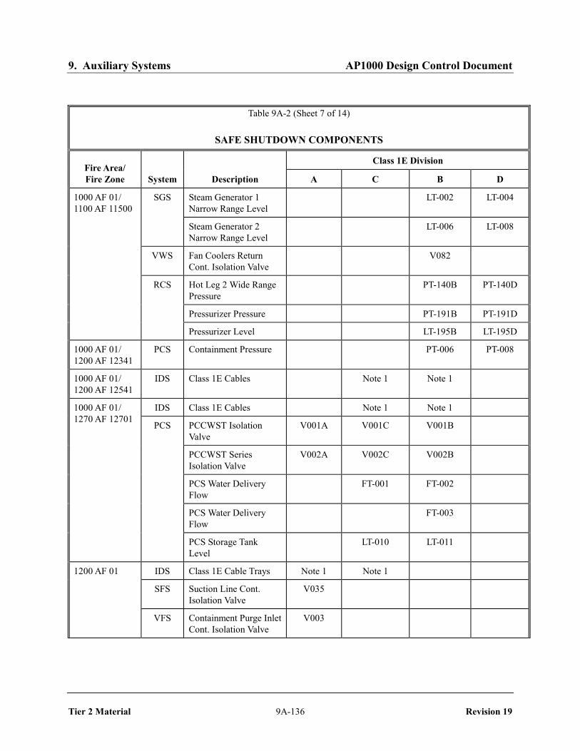
9. Auxiliary Systems AP1000 Design Control Document
Tier 2 Material 9A-136 Revision 19
Table 9A-2 (Sheet 7 of 14)
SAFE SHUTDOWN COMPONENTS
Fire Area/ Fire Zone System Description
Class 1E Division
A C B D
1000 AF 01/ 1100 AF 11500
SGS Steam Generator 1 Narrow Range Level
LT-002 LT-004
Steam Generator 2 Narrow Range Level
LT-006 LT-008
VWS Fan Coolers Return Cont. Isolation Valve
V082
RCS Hot Leg 2 Wide Range Pressure
PT-140B PT-140D
Pressurizer Pressure PT-191B PT-191D
Pressurizer Level LT-195B LT-195D
1000 AF 01/ 1200 AF 12341
PCS Containment Pressure PT-006 PT-008
1000 AF 01/ 1200 AF 12541
IDS Class 1E Cables Note 1 Note 1
1000 AF 01/ 1270 AF 12701
IDS Class 1E Cables Note 1 Note 1
PCS PCCWST Isolation Valve
V001A V001C V001B
PCCWST Series Isolation Valve
V002A V002C V002B
PCS Water Delivery Flow
FT-001 FT-002
PCS Water Delivery Flow
FT-003
PCS Storage Tank Level
LT-010 LT-011
1200 AF 01 IDS Class 1E Cable Trays Note 1 Note 1
SFS Suction Line Cont. Isolation Valve
V035
VFS Containment Purge Inlet Cont. Isolation Valve
V003

9. Auxiliary Systems AP1000 Design Control Document
Tier 2 Material 9A-137 Revision 19
Table 9A-2 (Sheet 8 of 14)
SAFE SHUTDOWN COMPONENTS
Fire Area/ Fire Zone System Description
Class 1E Division
A C B D
1200 AF 01 PSS Liquid Sample Line Cont. Isolation Valve
V011
Sample Return Line Cont. Isolation Valve
V023
Air Sample Line Cont. Isolation Valve
V046
SFS Discharge Line Cont. Isol. Valve
V038
VFS Containment Purge Discharge Cont. Isolation Valve
V010
VFS Vacuum Relief Containment Isolation Valve
V800A V800B
RNS Discharge Cont. Isolation Valve
V011
Suction Header Cont. Isolation Valve
V022
PCS Containment Pressure PT-005 PT-007
1200 AF 03 IDS Class 1E Cable Trays Note 1 Note 1
1201 AF 02 IDSB 24 Hr Battery 1A DB-1A
24 Hr Battery 1B DB-1B
72 Hr Battery 2A DB-2A
72 Hr Battery 2B DB-2B
250 Vdc Distribution Panel
DD-1
208/120 Vac Distribution Panel
EA-1
208/120 Vac Distribution Panel
EA-2
208/120 Vac Distribution Panel
EA-3
250 Vdc Switchboard DS-1

9. Auxiliary Systems AP1000 Design Control Document
Tier 2 Material 9A-138 Revision 19
Table 9A-2 (Sheet 9 of 14)
SAFE SHUTDOWN COMPONENTS
Fire Area/ Fire Zone System Description
Class 1E Division
A C B D
1201 AF 02 250 Vdc Switchboard DS-2
208/120 Vac Inverter DU-1
208/120 Vac Inverter DU-2
Regulating Transformer DT-1
Battery Charger DC-1
Battery Charger DC-2
Voltage to Class 1E Battery Charger
--- 002
Voltage to Class 1E Battery Charger
--- 006
PMS Protection and Safety Monitoring System Cabinets
IDSB Electrical Penetration EY-P32Y 250 Vdc MCC DK-1 Electrical Penetration EY-P30Z Electrical Penetration EY-P31Y
1201 AF 03 IDSD Battery 1A DB-1A Battery 1B DB-1B 250 Vdc Distribution
Panel DD-1
208/120 Vac Distribution Panel
EA-1
208/120 Vac Distribution Panel
EA-2
250 Vdc Switchboard DS-1 208/120 Vac Inverter DU-1 Regulating Transformer DT-1 Battery Charger DC-1 Voltage to Class 1E
Battery Charger --- 004
Voltage to Class 1E Battery Charger
--- 008
PMS Protection and Safety Monitoring System Cabinets

9. Auxiliary Systems AP1000 Design Control Document
Tier 2 Material 9A-139 Revision 19
Table 9A-2 (Sheet 10 of 14)
SAFE SHUTDOWN COMPONENTS
Fire Area/ Fire Zone System Description
Class 1E Division
A C B D
1201 AF 03 IDSD 250 Vdc MCC DK-1
Electrical Penetration EY-P14Z
Electrical Penetration EY-P15Y
Electrical Penetration EY-P16Z
1201 AF 04 IDS Class 1E Cable Trays Note 1
CAS Instrument Air Supply Cont. Isolation Valve
V014
CCS Inlet Line Cont. Isolation Valve
V200
CCS Outlet Line Cont. Isolation Valve
V208
PXS Nitrogen Supply Cont. Isolation Valve
V042
VWS Fan Coolers Supply Cont. Isolation Valve
V058
Fan Coolers Return Cont. Isolation Valve
V086
SGS SG 1 Steam Line Pressure
PT-031 PT-033
SG 1 Startup Feedwater Flow
FT-055A FT-055B
SG 2 Steam Line Pressure
PT-035 PT-037
SG 2 Startup Feedwater Flow
FT-056A FT-056B
1201 AF 05 CVS Hydrogen Addition Cont. Isolation Valve
V092
SGS Steam Gen. Blowdown Cont. Isolation Valve
V075A V074A
Steam Gen. Blowdown Cont. Isolation Valve
V074B V075B

9. Auxiliary Systems AP1000 Design Control Document
Tier 2 Material 9A-140 Revision 19
Table 9A-2 (Sheet 11 of 14)
SAFE SHUTDOWN COMPONENTS
Fire Area/ Fire Zone System Description
Class 1E Division
A C B D
1201 AF 05 PORV and Block Valve- SG 1 Cont. Isolation Valves
V027A V233A
Steam Line Cond. Drain Cont. Isolation Valve
V036A
Main Steam Line Cont. Isolation Valve
V040A V040A
Startup Feedwater Cont. Isolation Valve
V067A
Main Steam Line Cond. Drain Control Valve
V086A
MSIV Bypass Cont. Isolation Valve
V240A V240A
1201 AF 06 SGS PORV and Block Valve SG 2 Cont. Isolation Valve
V233B V027B
Steam Line Cond. Drain Cont. Isolation Valve
V036B
Main Steam Line Cont. Isolation Valve
V040B V040B
Main Feedwater Cont. Isolation Valve
V057B V057B
Startup Feedwater Cont. Isolation Valve
V067B
Steam Line Cond. Drain Control Valve
V086B
MSIV Bypass Cont. Isolation Valve
V240B V240B
1202 AF 03 IDSC 24 Hr Battery 1A DB-1A
24 Hr Battery 1B DB-1B
72 Hr Battery 2A DB-2A
72 Hr Battery 2B DB-2B
250 Vdc Distribution Panel
DD-1

9. Auxiliary Systems AP1000 Design Control Document
Tier 2 Material 9A-141 Revision 19
Table 9A-2 (Sheet 12 of 14)
SAFE SHUTDOWN COMPONENTS
Fire Area/ Fire Zone System Description
Class 1E Division
A C B D
1202 AF 03 IDSC 208/120 Vac Distribution Panel
EA-1
208/120 Vac Distribution Panel
EA-2
208/120 Vac Distribution Panel
EA-3
250 Vdc Switchboard DS-1
250 Vdc Switchboard DS-2
208/120 Vac Inverter DU-1
208/120 Vac Inverter DU-2
Regulating Transformer DT-1
Battery Charger DC-1
Battery Charger DC-2 Voltage to Class 1E
Battery Charger ---003
Voltage to Class 1E Battery Charger
---007
PMS Protection and Safety Monitoring System Cabinets
ECS 6900V RCP 1A Switchgear
ES-31
6900V RCP 2A Switchgear
ES-51
6900V RCP 1B Switchgear
ES-41
6900V RCP 2B Switchgear
ES-61
IDSC Electrical Penetration EY-P27Z Electrical Penetration EY-P29Y Electrical Penetration EY-P28Y 250 Vdc MCC DK-1

9. Auxiliary Systems AP1000 Design Control Document
Tier 2 Material 9A-142 Revision 19
Table 9A-2 (Sheet 13 of 14)
SAFE SHUTDOWN COMPONENTS
Fire Area/ Fire Zone System Description
Class 1E Division
A C B D
1202 AF 04 IDSA Battery 1A DB-1A Battery 1B DB-1B 250 Vdc Distribution
Panel DD-1
208/120 Vac Distribution Panel
EA-1
208/120 Vac Distribution Panel
EA-2
250 Vdc Switchboard DS-1 208/120 Vac Inverter DU-1 Regulating Transformer DT-1 Battery Charger DC-1 Voltage to Class 1E
Battery Charger --- 001
Voltage to Class 1E Battery Charger
--- 005
PMS Protection and Safety Monitoring System Cabinets
1202 AF 05 PMS Transfer Switch Set JW-004A JW-004C JW-004B JW-004D
1210 AF 01 IDS Spare Battery (DB-1A) Note 1 Note 1 Note 1 Note 1
Spare Battery (DB-1B) Note 1 Note 1 Note 1 Note 1
Spare Battery Charger (DC-1)
Note 1 Note 1 Note 1 Note 1
Spare Fuse Transfer Box (DF-1)
Note 1 Note 1 Note 1 Note 1
1220 AF 01 IDS Class 1E Cable Trays Note 1 Note 1
ECS 6900V RCP 1A Switchgear
ES-32
6900V RCP 2A Switchgear
ES-52
6900V RCP 1B Switchgear
ES-42

9. Auxiliary Systems AP1000 Design Control Document
Tier 2 Material 9A-143 Revision 19
Table 9A-2 (Sheet 14 of 14)
SAFE SHUTDOWN COMPONENTS
Fire Area/ Fire Zone System Description
Class 1E Division
A C B D
1220 AF 01 ECS 6900V RCP 2B Switchgear
ES-62
1220 AF 02 CVS Letdown Containment Isolation Valve
V047
Makeup Line Cont. Isolation Valve
V090
WLS Sump Discharge Cont. Isolation Valve
V057
RCDT Gas Outlet Cont. Isolation Valve
V068
1230 AF 01 IDS Class 1E Cable Trays Note 1 Note 1
1230 AF 02 IDS Class 1E Cable Trays Note 1 Note 1
1232 AF 01 Remote Shutdown Room
IDS Class 1E Cable Trays Note 1 Note 1 Note 1 Note 1
1240 AF 01 IDS Class 1E Cable Trays Note 1 Note 1
1242 AF 01 MCR Workstation
IDS Class 1E Cable Trays Note 1 Note 1 Note 1 Note 1
1242 AF 02 IDSA Class 1E Electrical Penetration
EY-P11Z
Class 1E Electrical Penetration
EY-P12Y
Class 1E Electrical Penetration
EY-P13Y
250 Vdc MCC DK-1
1243 AF 01 Reactor Trip Switchgear I
IDS Class 1E Cables Note 1 Note 1 Note 1 Note 1
1243 AF 02 Reactor Trip Switchgear II
IDS Class 1E Cables Note 1 Note 1 Note 1 Note 1
Note1. This represents equipment such as cables that have no associated tag number.
:

9. Auxiliary Systems AP1000 Design Control Document
Tier 2 Material 9A-144 Revision 19
Table 9A-3 (Sheet 1 of 24)
FIRE PROTECTION SUMMARY Comb. Boundary Floor Fire Heat Load, Equiv. Fire Fixed Fire Area/ Safety Area Combust. Sev. Value Btu/ Dur. Res.(4) Detect. Suppression Zone(1) Area?(2) Sq Ft Material(3) Cat. Amount (Btu) Sq Ft (Min) (Hours) Cap. Capability(5)
1000 AF 01 YES 3 SMOKE SEE ZONE HEAT 1100 AF 11105 CABLE INS C 100 1.0E+06 HOSE STATION REACTOR CAVITY 260 NET CAT. C TOTAL: 1.0E+06 3900 2 1100 AF 11204 CABLE INS C 100 1.0E+06 HOSE STATION VERTICAL ACCESS/ 790 NET CAT. C TOTAL: 1.0E+06 1300 1 RCDT ROOM 1100 AF 11206 CABLE INS C 200 2.0E+06 HOSE STATION PXS VALVE/ 790 NET CAT. C TOTAL: 2.0E+06 2600 1 ACCUMULATOR ROOM A 1100 AF 11207 CABLE INS C 200 2.0E+06 HOSE STATION PXS VALVE/ 750 NET CAT. C TOTAL: 2.0E+06 2700 1 ACCUMULATOR ROOM B 1100 AF 11208 CABLE INS C 200 2.0E+06 HOSE STATION RNS VALVE ROOM 310 NET CAT. C TOTAL: 2.0E+06 6600 5 1100 AF 11209 CABLE INS C 500 5.1E+06 HOSE STATION CVS ROOM 570 NET CAT. C TOTAL: 5.1E+06 8900 7 1100 AF 11300A CABLE INS C 2500 2.6E+07 HOSE STATION MAINTENANCE FLOOR TRASH B 500 3.9E+06 SOUTHEAST VOLATILES E 10 1.4E+06 1550 NET CAT. D TOTAL: 3.1E+07 20,000 15 1100 AF 11300B CABLE INS C 10000 1.0E+08 WATER SPRAY MAINTENANCE FLOOR TRASH B 1000 7.7E+06 HOSE STATION NORTH VOLATILES E 40 5.4E+06 3725 NET CAT. D TOTAL: 1.2E+08 31,000 23 1100 AF 11300C NEGLIGIBLE HOSE STATION MAINTENANCE FLOOR WEST 1100 AF 11301 CABLE INS C 500 5.1E+06 HOSE STATION SG COMPARTMENT 1 810 NET CAT. C TOTAL: 5.1E+06 6300 5 1100 AF 11302 CABLE INS C 500 5.1E+06 HOSE STATION SG COMPARTMENT 2 620 NET CAT. C TOTAL: 5.1E+06 8200 6 1100 AF 11303 CABLE INS C 200 2.0E+06 HOSE STATION PRESSURIZER 220 NET CAT. C TOTAL: 2.0E+06 9300 7 COMPARTMENT 1100 AF 11303A CABLE INS C 100 1.0E+06 HOSE STATION LOWER ADS VALVE AREA 144 NET CAT. C TOTAL: 1.0E+06 7100 5 1100 AF 11303B CABLE INS C 100 1.0E+06 HOSE STATION UPPER ADS VALVE AREA 144 NET CAT. C TOTAL: 1.0E+06 7100 5

9. Auxiliary Systems AP1000 Design Control Document
Tier 2 Material 9A-145 Revision 19
Table 9A-3 (Sheet 2 of 24)
FIRE PROTECTION SUMMARY Comb. Boundary Floor Fire Heat Load, Equiv. Fire Fixed Fire Area/ Safety Area Combust. Sev. Value Btu/ Dur. Res.(4) Detect. Suppression Zone(1) Area?(2) Sq Ft Material(3) Cat. Amount (Btu) Sq Ft (Min) (Hours) Cap. Capability(5)
1100 AF 11500 CABLE INS C 12000 1.2E+08 HOSE STATION OPERATING DECK AND PAPER C 500 3.9E+06 REFUELING CAVITY VOLATILES E 55 7.5E+06 LUBE OIL E 10 1.5E+06 11150 NET CAT. D TOTAL: 1.4E+08 12000 9 1200 AF 12341 CABLE INS C 4000 4.1E+07 NONE MIDDLE ANNULUS RUBBER D 1200 1.5E+07 1845 NET CAT. D TOTAL: 5.5E+07 30000 22 1200 AF 12541 CABLE INS C 500 5.1E+06 NONE UPPER ANNULUS 1685 NET CAT. C TOTAL: 5.1E+06 3000 1 1270 AF 12701 CABLE INS C 500 5.1E+06 NONE PCS VALVE ROOM 800 NET CAT. C TOTAL: 5.1E+06 6400 5 1250 AF 12555 CABLE INS C 4000 4.1E+07 HOSE STATION VES AIR STORAGE/ PAPER C 1000 7.7E+06 OPERATING DECK TRASH B 1000 7.7E+06 STAGING AREA CLOTH B 500 4.0E+06 WOOD C 500 4.2E+06 PLASTIC D 500 6.6E+06 RUBBER D 100 1.2E+06 VOLATILES E 10 1.4E+06 1200 NET CAT. D TOTAL: 7.4E+07 61000 49 FIRE AREA TOTAL: 27363 NET CAT. D TOTAL: 4.5E+08 16000 12
1200 AF 01 YES 3 SMOKE SEE ZONE 1200 AF 12241 CABLE INS C 200 2.0E+06 HOSE STATION LOWER ANNULUS 1800 NET CAT. C TOTAL: 2.0E+06 1100 1 1200 AF 12461 CABLE INS C 1000 1.0E+07 HOSE STATION CORRIDOR TRASH B 200 1.5E+06 480 NET CAT. C TOTAL: 1.2E+07 24000 19 1205 AF 12362 CABLE INS C 500 5.1E+06 RNS HX ROOM VOLATILES E 10 1.4E+06 275 NET CAT. E TOTAL: 6.5E+06 23000 18 1205 AF 12365 CABLE INS C 500 5.1E+06 WASTE MONITOR PAPER C 100 7.7E+05 TANK ROOM B VOLATILES E 5 6.8E+05 330 NET CAT. D TOTAL: 6.6E+06 20000 15 1210 AF 12151 CABLE INS C 8000 8.2E+07 HOSE STATION DEMIN./FILTER, LUBE OIL E 10 1.5E+06 WLS & WGS VOLATILES E 10 1.4E+06 EQUIPMENT ROOMS PAPER C 100 7.7E+05 1890 NET CAT. D TOTAL: 8.5E+07 45000 34

9. Auxiliary Systems AP1000 Design Control Document
Tier 2 Material 9A-146 Revision 19
Table 9A-3 (Sheet 3 of 24)
FIRE PROTECTION SUMMARY Comb. Boundary Floor Fire Heat Load, Equiv. Fire Fixed Fire Area/ Safety Area Combust. Sev. Value Btu/ Dur. Res.(4) Detect. Suppression Zone(1) Area?(2) Sq Ft Material(3) Cat. Amount (Btu) Sq Ft (Min) (Hours) Cap. Capability(5)
1210 AF 12171 CABLE INS C 2000 2.0E+07 HOSE STATION EFFLUENT HOLDUP PAPER C 500 3.9E+06 TANK ROOM A VOLATILES E 10 1.4E+06 785 NET CAT. D TOTAL: 2.6E+07 33000 25 1214 AF 12152 CABLE INS C 500 5.1E+06 HOSE STATION PRIMARY SAMPLE PAPER C 100 7.7E+05 ROOM PLASTIC D 200 2.6E+06 280 NET CAT. D TOTAL: 8.5E+06 30000 23 1214 AF 12154 CABLE INS C 200 2.0E+06 HOSE STATION AUX. BLDG SUMP AND 190 NET CAT. C TOTAL: 2.0E+06 11000 8 SFS PENETRATION ROOM 1214 AF 12354 CABLE INS C 200 2.0E+06 MID ANNULUS 200 NET CAT. C TOTAL: 2.0E+06 10000 8 ACCESS ROOM 1215 AF 12161 CABLE INS C 1000 1.0E+07 HOSE STATION CORRIDOR 580 NET CAT. D TOTAL: 1.0E+07 17000 14 1215 AF 12162 CABLE INS. C 500 5.1E+06 RNS PUMP ROOM A LUBE OIL E 5 7.6E+05 205 NET. CAT. D TOTAL 5.9E+06 29000 22 1216 AF 12166 CABLE INS C 200 2.0E+06 HOSE STATION WASTE HOLDUP VOLATILES E 10 1.4E+06 TANK ROOM A 280 NET CAT. E TOTAL: 3.4E+06 12000 9 1216 AF 12167 CABLE INS C 200 2.0E+06 HOSE STATION WASTE HOLDUP VOLATILES E 10 1.4E+06 TANK ROOM B 300 NET CAT. E TOTAL: 3.4E+06 11000 9 1216 AF 12169 CABLE INS C 1000 1.0E+07 HOSE STATION WLS PUMP ROOM/ LUBE OIL E 5 7.6E+05 CORRIDOR VOLATILES E 10 1.4E+06 475 NET CAT. E TOTAL: 1.1E+07 23000 17 1216 AF 12172 CABLE INS C 2000 2.0E+07 HOSE STATION EFFLUENT HOLDUP PAPER C 500 3.9E+06 TANK ROOM B VOLATILES E 10 1.4E+06 795 NET CAT. D TOTAL: 2.6E+07 32000 24 1216 AF 12264 CABLE INS C 500 5.1E+06 HOSE STATION WASTE MONITOR VOLATILES E 10 1.4E+06 TANK ROOM C & CHEM. 660 NET CAT. E TOTAL: 6.5E+06 9800 7 WASTE TANK ROOM 1220 AF 12251 CABLE INS C 7000 7.1E+07 WET PIPE (6) DEMIN./FILTER PAPER C 1000 7.7E+06 SPRINKLER ACCESS AREA AND PLASTIC D 200 2.6E+06 HOSE STATION CVS MAKEUP PUMP LUBE OIL E 5 7.6E+05 ROOMS VOLATILES E 10 1.4E+06 1750 NET CAT. D TOTAL: 8.4E+07 48000 37

9. Auxiliary Systems AP1000 Design Control Document
Tier 2 Material 9A-147 Revision 19
Table 9A-3 (Sheet 4 of 24)
FIRE PROTECTION SUMMARY Comb. Boundary Floor Fire Heat Load, Equiv. Fire Fixed Fire Area/ Safety Area Combust. Sev. Value Btu/ Dur. Res.(4) Detect. Suppression Zone(1) Area?(2) Sq Ft Material(3) Cat. Amount (Btu) Sq Ft (Min) (Hours) Cap. Capability(5) 1220 AF 12256 CABLE INS. C 400 4.1E+06 EL 92′-6″ PIPE 1000 NET CAT. C TOTAL: 4.1E+06 4100 2 CHASE/VALVE ROOM 1220 AF 12269 CABLE INS C 100 1.0E+06 HOSE STATION EL 92′-6″ PIPE CHASE 800 NET CAT. C TOTAL: 1.0E+06 1300 1 1220 AF 12271 CABLE INS C 5000 5.1E+07 HOSE STATION SFS EQUIPMENT ROOMS LUBE OIL E 10 1.5E+06 VOLATILES E 10 1.4E+06 1190 NET CAT. D TOTAL: 5.4E+07 45000 34 1224 AF 12252 CABLE INS C 800 8.2E+06 HOSE STATION RADIOACTIVE PAPER C 500 3.9E+06 CHEMISTRY PLASTIC D 500 6.6E+06 LABORATORY VOLATILES E 5 6.8E+05 285 NET CAT. D TOTAL: 1.9E+07 68000 55 1225 AF 12261 CABLE INS C 3000 3.1E+07 HOSE STATION WLS PUMP ROOM LUBE OIL E 5 7.6E+05 AND CORRIDOR VOLATILES E 5 6.8E+05 865 NET CAT. D TOTAL: 3.2E+07 37000 28 1225 AF 12262 CABLE INS. C 200 2.0E+06 PIPING/VALVE ROOM VOLATILES E 5 6.8E+05 475 NET. CAT. C TOTAL: 2.7E+06 6000 4 1234 AF 12351 CABLE INS C 4000 4.1E+07 MAINTENANCE PAPER C 1000 7.7E+06 FLOOR STAGING AREA WOOD C 1000 8.4E+06 TRASH B 1000 7.7E+06 CLOTH B 500 4.0E+06 PLASTIC D 500 6.6E+06 RUBBER D 200 2.4E+06 VOLATILES E 50 6.8E+06 1100 NET CAT. E TOTAL: 8.4E+07 77000 58 1234 AF 12352 CABLE INS C 500 5.1E+06 ELEVATION 107′-2″ TRASH B 200 1.5E+06 PERSONNEL HATCH 265 NET CAT. C TOTAL: 6.6E+06 25000 19 1235 AF 12361 CABLE INS C 2000 2.0E+07 HOSE STATION CORRIDOR TRASH B 500 3.9E+06 480 NET CAT. C TOTAL: 2.4E+07 51000 39 1235 AF 12363 CABLE INS C 500 5.1E+06 WASTE MONITOR PAPER C 100 7.7E+05 TANK ROOM A VOLATILES E 5 6.8E+05 275 NET CAT. D TOTAL: 6.6E+06 24000 18 1244 AF 12451 CABLE INS C 450 4.6E+06 SECURITY ROOM PAPER C 500 3.9E+06 308 NET CAT. C TOTAL: 8.5E+06 27600 28 1244 AF 12452 CABLE INS C 600 6.1E+06 VFS PENETRATION ROOM 265 NET CAT. C TOTAL: 6.1E+06 23100 20 1244 AF 12454 CABLE INS C 200 2.0E+06 VFS/SFS/PSS 190 NET CAT. C TOTAL: 2.0E+06 11000 8 PENETRATION ROOM

9. Auxiliary Systems AP1000 Design Control Document
Tier 2 Material 9A-148 Revision 19
Table 9A-3 (Sheet 5 of 24)
FIRE PROTECTION SUMMARY Comb. Boundary Floor Fire Heat Load, Equiv. Fire Fixed Fire Area/ Safety Area Combust. Sev. Value Btu/ Dur. Res.(4) Detect. Suppression Zone(1) Area?(2) Sq Ft Material(3) Cat. Amount (Btu) Sq Ft (Min) (Hours) Cap. Capability(5)
1250 AF 12561 CABLE INS C 1000 1.0E+07 HOSE STATION CCS VALVE ROOM AND VOLATILES E 5 6.8E+05 ACCESS CORRIDOR 630 NET CAT. D TOTAL: 1.1E+07 17000 13 1254 AF 12553 CABLE INS C 5000 5.1E+07 ELEVATION 135′-3″ PAPER C 1000 7.7E+06 PERSONNEL ACCESS TRASH B 500 3.9E+06 AREA VOLATILES E 10 1.4E+06 1350 NET CAT. D TOTAL: 6.4E+07 47000 36 1244 AF 12451 CABLE INS C 400 4.1E+06 SECURITY ROOM PAPER C 500 3.8E+06 308 NET CAT. C TOTAL: 7.9E+06 25900 22 1254 AF 12554 CABLE INS C 400 4.1E+06 SECURITY ROOM PAPER C 1000 7.7E+06 268 NET CAT. C TOTAL: 1.2E+07 62000 51 1264 AF 12651 CABLE INS C 5000 5.1E+07 VAS EQUIPMENT LUBE OIL E 10 1.5E+06 ROOM VOLATILES E 10 1.4E+06 1480 NET CAT. D TOTAL: 5.4E+07 36000 27 FIRE AREA TOTAL: 22501 NET CAT. D TOTAL: 6.9E+08 30700 24 HOSE STATION
1200 AF 02 YES 3/0 SMOKE SEE ZONE 1200 AF 12562 CABLE INS C 10000 1.0E+08 HOSE STATION FUEL HANDLING AREA PAPER C 1500 1.2E+07 WOOD C 1000 8.4E+06 TRASH B 1000 7.7E+06 CLOTH B 500 4.0E+06 PLASTIC D 500 6.6E+06 LUBE OIL E 15 2.3E+06 VOLATILES E 5 6.8E+05 4725 NET CAT. D TOTAL: 1.4E+08 30000 23 1230 AF 12371 CABLE INS C 3000 3.1E+07 WET PIPE(6) RAIL CAR BAY/ PAPER C 1000 7.7E+06 SPRINKLER FILTER STORAGE AREA WOOD C 1000 8.4E+06 HOSE STATION TRASH B 1000 7.7E+06 LUBE OIL E 10 1.5E+06 FUEL OIL E 100 1.4E+07 1460 NET CAT. D TOTAL: 7.0E+07 48000 37 1236 AF 12372 CABLE INS C 200 2.0E+06 HOSE STATION RESIN TRANSFER PUMP/ LUBE OIL E 5 7.6E+05 VALVE ROOM 80 NET CAT. E TOTAL: 2.8E+06 35000 26 1236 AF 12373 CABLE INS C 200 2.0E+06 HOSE STATION SPENT RESIN TANK ROOM 70 NET CAT. C TOTAL: 2.0E+06 29000 22 1246 AF 12471 CABLE INS C 200 2.0E+06 HOSE STATION WSS VALVE/PIPING AREA 90 NET CAT. C TOTAL: 2.0E+06 23000 17 FIRE AREA TOTAL: 6425 NET CAT. D TOTAL: 2.2E+08 34000 26 HOSE STATION

9. Auxiliary Systems AP1000 Design Control Document
Tier 2 Material 9A-149 Revision 19
Table 9A-3 (Sheet 6 of 24)
FIRE PROTECTION SUMMARY Comb. Boundary Floor Fire Heat Load, Equiv. Fire Fixed Fire Area/ Safety Area Combust. Sev. Value Btu/ Dur. Res.(4) Detect. Suppression Zone(1) Area?(2) Sq Ft Material(3) Cat. Amount (Btu) Sq Ft (Min) (Hours) Cap. Capability(5)
1200 AF 03 YES 3 SMOKE HOSE STATION 1230 AF 12311 CABLE INS C 1200 1.2E+07 CORRIDOR 355 NET CAT. C TOTAL: 1.2E+07 34000 25 1242 AF 12411 CABLE INS C 1200 1.2E+07 CORRIDOR 300 NET CAT. C TOTAL: 1.2E+07 41000 30 FIRE AREA TOTAL: 655 NET CAT. C TOTAL: 2.4E+07 37000 28
1201 AF 01 NO 2 NONE NONE STAIRWELL S02 NEGLIGIBLE
1201 AF 02 YES 3 SMOKE HOSE STATION 1211 AF 12104 BATTERIES A 120 2.4E+07 DIVISION B BATTERY CABLE INS C 1000 1.0E+07 ROOM 1 560 NET CAT. C TOTAL: 3.4E+07 61000 50 1221 AF 12204 BATTERIES A 120 2.4E+07 DIVISION B BATTERY CABLE INS C 1000 1.0E+07 ROOM 2 560 NET CAT. C TOTAL: 3.4E+07 61000 50 1222 AF 12207 CABLE INS C 2500 2.6E+07 DIVISION B 395 NET CAT. C TOTAL: 2.6E+07 65000 54 DC EQUIPMENT ROOM 1231 AF 12304 CABLE INS C 3500 3.6E+07 DIVISION B I&C/ 585 NET CAT. C TOTAL: 3.6E+07 61000 50 PENETRATION ROOM FIRE AREA TOTAL: 2100 NET CAT. C TOTAL: 1.3E+08 62000 51
1201 AF 03 YES 3 SMOKE HOSE STATION 1211 AF 12105 BATTERIES A 120 2.4E+07 DIVISION D BATTERY CABLE INS C 1000 1.0E+07 ROOM 560 NET CAT. C TOTAL: 3.4E+07 61000 50 1221 AF 12205 CABLE INS C 3500 3.6E+07 DIVISION D DC 560 NET CAT. C TOTAL: 3.6E+07 64000 53 EQUIPMENT ROOM 1231 AF 12305 CABLE INS C 3500 3.6E+07 DIVISION D I&C/ 550 NET CAT. C TOTAL: 3.6E+07 65000 55 PENETRATION ROOM FIRE AREA TOTAL: 1670 NET CAT. C TOTAL: 1.1E+08 63000 53

9. Auxiliary Systems AP1000 Design Control Document
Tier 2 Material 9A-150 Revision 19
Table 9A-3 (Sheet 7 of 24)
FIRE PROTECTION SUMMARY Comb. Boundary Floor Fire Heat Load, Equiv. Fire Fixed Fire Area/ Safety Area Combust. Sev. Value Btu/ Dur. Res.(4) Detect. Suppression Zone(1) Area?(2) Sq Ft Material(3) Cat. Amount (Btu) Sq Ft (Min) (Hours) Cap. Capability(5)
1201 AF 04 YES 3 SMOKE HOSE STATION 1241 AF 12405 CABLE INS C 3000 3.1E+07 LOWER VBS B&D PAPER C 1000 7.7E+06 EQUIPMENT ROOM VOLATILES E 5 6.8E+05 670 NET CAT. C TOTAL: 3.9E+07 58000 47 1251 AF 12505 CABLE INS C 3000 3.1E+07 UPPER VBS B&D PAPER C 1000 7.7E+06 EQUIPMENT ROOM VOLATILES E 5 6.8E+05 705 NET CAT. C TOTAL: 3.9E+07 55000 44 FIRE AREA TOTAL: 1375 NET CAT. C TOTAL: 7.8E+07 57000 46
1201 AF 05 YES 3 SMOKE HOSE STATION 1231 AF 12306 CABLE INS C 2500 2.6E+07 VALVE/PIPING 600 NET CAT. C TOTAL: 2.6E+07 43000 31 PENETRATION ROOM 1241 AF 12506 CABLE INS C 3000 3.1E+07 MSIV COMPARTMENT A LUBE OIL E 40 6.0E+06 705 NET CAT. C TOTAL: 3.7E+07 52000 40 FIRE AREA TOTAL: 1305 NET CAT. C TOTAL: 6.2E+07 48000 37
1201 AF 06 YES 3 SMOKE HOSE STATION MSIV COMPARTMENT B CABLE INS C 3000 3.1E+07 LUBE OIL E 40 6.0E+06 FIRE AREA TOTAL : 695 NET CAT. E TOTAL: 3.7E+07 53000 40
1202 AF 01 NO 2 NONE NONE STAIRWELL S01 NEGLIGIBLE
1202 AF 02 NO 2 SMOKE HOSE STATION NORTHEAST ELEVATOR CABLE INS C 600 6.1E+06 SHAFT/MACHINE ROOM LUBRICANT E 5 9.9E+04 FIRE AREA TOTAL: 205 NET CAT. E TOTAL: 6.2E+06 30000 23

9. Auxiliary Systems AP1000 Design Control Document
Tier 2 Material 9A-151 Revision 19
Table 9A-3 (Sheet 8 of 24)
FIRE PROTECTION SUMMARY Comb. Boundary Floor Fire Heat Load, Equiv. Fire Fixed Fire Area/ Safety Area Combust. Sev. Value Btu/ Dur. Res.(4) Detect. Suppression Zone(1) Area?(2) Sq Ft Material(3) Cat. Amount (Btu) Sq Ft (Min) (Hours) Cap. Capability(5)
1202 AF 03 YES 3 SMOKE HOSE STATION 1212 AF 12102 BATTERIES A 120 2.4E+07 DIVISION C BATTERY CABLE INS C 1000 1.0E+07 ROOM 1 560 NET CAT. C TOTAL: 3.4E+07 61000 50 1222 AF 12202 BATTERIES A 120 2.4E+07 DIVISION C BATTERY CABLE INS C 1000 1.0E+07 ROOM 2 560 NET CAT. C TOTAL: 3.4E+07 61000 50 1222 AF 12203 CABLE INS C 2500 2.6E+07 DIVISION C DC 395 NET CAT. C TOTAL: 2.6E+07 65000 54 EQUIPMENT ROOM 1232 AF 12302 CABLE INS C 3500 3.6E+07 DIVISION C I&C ROOM 550 NET CAT. C TOTAL: 3.6E+07 65000 55 1232 AF 12312 CABLE INS C 1500 1.5E+07 DIVISION C RCP TRIP 395 NET CAT. C TOTAL: 1.5E+07 39000 29 SWITCHGEAR ROOM 1232 AF 12313 CABLE INS C 2500 2.6E+07 I&C/DIVISION C 555 NET CAT. C TOTAL: 2.6E+07 46000 35 PENETRATION ROOM FIRE AREA TOTAL: 3015 NET CAT. C TOTAL: 1.7E+08 57000 45
1202 AF 04 YES 3 SMOKE HOSE STATION 1212 AF 12101 BATTERIES A 120 2.4E+07 DIVISION A BATTERY CABLE INS C 1000 1.0E+07 ROOM 525 NET CAT. C TOTAL: 3.4E+07 65000 55 1222 AF 12201 CABLE INS C 3500 3.6E+07 DIVISION A DC 525 NET CAT. C TOTAL: 3.6E+07 68000 58 EQUIPMENT ROOM 1232 AF 12301 CABLE INS C 3500 3.6E+07 DIVISION A I&C ROOM 550 NET CAT. C TOTAL: 3.6E+07 65000 55 FIRE AREA TOTAL: 1600 NET CAT. C TOTAL: 1.1E+08 66000 56
1202 AF 05 NO 3 SMOKE NONE STAIRWELL S05 NEGLIGIBLE
1204 AF 01 NO 3 SMOKE HOSE STATION CABLE INS C 500 5.0E+06 RNS PUMP ROOM B LUBE OIL E 5 7.6E05 205 NET CAT. D TOTAL: 5.8E+06 28000 23 FIRE AREA TOTAL: 205 NET CAT. D TOTAL: 5.8E+06 28000 23

9. Auxiliary Systems AP1000 Design Control Document
Tier 2 Material 9A-152 Revision 19
Table 9A-3 (Sheet 9 of 24)
FIRE PROTECTION SUMMARY Comb. Boundary Floor Fire Heat Load, Equiv. Fire Fixed Fire Area/ Safety Area Combust. Sev. Value Btu/ Dur. Res.(4) Detect. Suppression Zone(1) Area?(2) Sq Ft Material(3) Cat. Amount (Btu) Sq Ft (Min) (Hours) Cap. Capability(5)
1204 AF 02 NO 2/0 NONE NONE STAIRWELL S03 NEGLIGIBLE
1204 AF 03 NO 2/0 SMOKE HOSE STATION SHIELD BLDG CABLE INS C 600 6.1E+06 ELEVATOR LUBRICANT E 5 9.9E+04 FIRE AREA TOTAL: 195 NET CAT. C TOTAL: 6.2E+06 32000 24
1205 AF 01 NO 2 NONE NONE STAIRWELL S04 NEGLIGIBLE
1205 AF 02 NO 2 SMOKE HOSE STATION SOUTHEAST ELEVATOR CABLE INS C 600 6.1E+06 SHAFT/MACHINE ROOM LUBRICANT E 5 9.9E+04 FIRE AREA TOTAL: 195 NET CAT. C TOTAL: 6.2E+06 32000 24
1210 AF 01 YES 3 SMOKE HOSE STATION 1210 AF 12111 CABLE INS C 3000 3.1E+07 CORRIDOR TRASH B 500 3.9E+06 1535 NET CAT. C TOTAL: 3.4E+07 22000 16 1212 AF 12103 BATTERIES A 120 2.4E+07 SPARE BATTERY CABLE INS C 1000 1.0E+07 ROOM 825 NET CAT. C TOTAL: 3.4E+07 41000 30 1212 AF 12112 CABLE INS C 500 5.1E+06 SPARE ROOM PAPER C 1000 7.7E+06 PLASTIC D 500 6.6E+06 CLOTH B 100 8.0E+05 TRASH B 100 7.7E+05 VOLATILES E 10 1.4E+06 340 NET CAT. D TOTAL: 2.2E+07 66000 53 1212 AF 12113 CABLE INS C 1500 1.5E+07 SPARE BATTERY 190 NET CAT. C TOTAL: 1.5E+07 81000 73 CHARGER ROOM FIRE AREA TOTAL: 2890 NET CAT. C TOTAL: 1.1E+08 37000 27

9. Auxiliary Systems AP1000 Design Control Document
Tier 2 Material 9A-153 Revision 19
Table 9A-3 (Sheet 10 of 24)
FIRE PROTECTION SUMMARY Comb. Boundary Floor Fire Heat Load, Equiv. Fire Fixed Fire Area/ Safety Area Combust. Sev. Value Btu/ Dur. Res.(4) Detect. Suppression Zone(1) Area?(2) Sq Ft Material(3) Cat. Amount (Btu) Sq Ft (Min) (Hours) Cap. Capability(5)
1220 AF 01 YES 3 SMOKE HOSE STATION 1220 AF 12211 CABLE INS C 3000 3.1E+07 CORRIDOR TRASH B 500 3.9E+06 1510 NET CAT. C TOTAL: 3.4E+07 23000 17 1222 AF 12212 CABLE INS C 1500 1.5E+07 DIVISION B RCP TRIP 340 NET CAT. C TOTAL: 1.5E+07 45000 34 SWITCHGEAR ROOM 1222 AF 12213 CABLE INS C 1000 1.0E+07 SPARE ROOM AND PAPER C 200 1.5E+06 MOTOR CONTROL CTRS TRASH B 100 7.7E+05 190 NET CAT. C TOTAL: 1.3E+07 66000 56 FIRE AREA TOTAL: 2040 NET CAT. C TOTAL: 6.2E+07 31000 23
1220 AF 02 YES 3 SMOKE HOSE STATION LOWER ANNULUS CABLE INS C 500 5.1E+06 VALVE AREA FIRE AREA TOTAL: 220 NET CAT. C TOTAL: 5.1E+06 23000 13
1230 AF 01 YES 3 SMOKE HOSE STATION CORRIDOR CABLE INS C 2500 2.6E+07 FIRE AREA TOTAL: 770 NET CAT. C TOTAL: 2.6E+07 33000 24
1230 AF 02 YES 3 SMOKE HOSE STATION NON-1E EQUIPMENT/ CABLE INS C 3500 3.6E+07 PREACTION PENETRATION ROOM SPRINKLER FIRE AREA TOTAL: 870 NET CAT. C TOTAL: 3.6E+07 41000 30
1232 AF 01 YES 3 SMOKE HOSE STATION REMOTE SHUTDOWN CABLE INS C 1500 1.5E+07 ROOM PAPER C 1000 7.7E+06 PLASTIC D 500 6.6E+06 FIRE AREA TOTAL: 410 NET CAT. C TOTAL: 3.0E+07 72000 63
1240 AF 01 YES 3 SMOKE HOSE STATION NON-1E EQUIPMENT/ CABLE INS C 3500 3.6E+07 PENETRATION ROOM FIRE AREA TOTAL: 800 NET CAT. C TOTAL: 3.6E+07 45000 34

9. Auxiliary Systems AP1000 Design Control Document
Tier 2 Material 9A-154 Revision 19
Table 9A-3 (Sheet 11 of 24)
FIRE PROTECTION SUMMARY Comb. Boundary Floor Fire Heat Load, Equiv. Fire Fixed Fire Area/ Safety Area Combust. Sev. Value Btu/ Dur. Res.(4) Detect. Suppression Zone(1) Area?(2) Sq Ft Material(3) Cat. Amount (Btu) Sq Ft (Min) (Hours) Cap. Capability(5)
1242 AF 01 YES 3 SMOKE HOSE STATION 1242 AF 12401A CABLE INS C 4000 4.1E+07 MCR MAIN CONTROL PAPER C 3500 2.7E+07 AREA/TAGGING PLASTIC D 1000 1.3E+07 ROOM/VESTIBULE CARPET D 1159 1.5E+07 1545 NET CAT. C TOTAL: 9.60E+07 62000 50 1242 AF 12401B CABLE INS C 2000 2.0E+07 MCR SHIFT SUP'R/ PAPER C 2000 1.5E+07 CLERK/OPERATOR PLASTIC D 1000 1.3E+07 AREAS CARPET D 538 7.1E+06 CHARCOAL C 100 1.5E+06 845 NET CAT. C TOTAL: 5.8E+07 68000 56 FIRE AREA TOTAL: 2390 NET CAT. C TOTAL: 1.5E+08 64000 52
1242 AF 02 YES 3 SMOKE HOSE STATION DIVISION A CABLE INS C 2000 2.0E+07 ELECTRICAL PENETRATION ROOM FIRE AREA TOTAL: 450 NET CAT. C TOTAL: 2.0E+07 45000 34
1243 AF 01 YES 3 SMOKE HOSE STATION REACTOR TRIP CABLE INS C 500 5.1E+06 SWITCHGEAR 1 FIRE AREA TOTAL: 95 NET CAT. C TOTAL: 5.1E+06 54000 42
1243 AF 02 YES 3 SMOKE HOSE STATION REACTOR TRIP CABLE INS C 500 5.1E+06 SWITCHGEAR 2 FIRE AREA TOTAL: 95 NET CAT. C TOTAL: 5.1E+06 54000 42
1250 AF 01 NO 3 SMOKE HOSE STATION VBS MCR/A&C CABLE INS C 12000 1.2E+08 EQUIPMENT ROOM CHARCOAL C 5000 7.3E+07 CHARCOAL BED LUBE OIL E 20 3.0E+06 DELUGE VOLATILES E 10 1.4E+06 FIRE AREA TOTAL: 3575 NET CAT. D TOTAL: 2.0E+08 56000 44

9. Auxiliary Systems AP1000 Design Control Document
Tier 2 Material 9A-155 Revision 19
Table 9A-3 (Sheet 12 of 24)
FIRE PROTECTION SUMMARY Comb. Boundary Floor Fire Heat Load, Equiv. Fire Fixed Fire Area/ Safety Area Combust. Sev. Value Btu/ Dur. Res.(4) Detect. Suppression Zone(1) Area?(2) Sq Ft Material(3) Cat. Amount (Btu) Sq Ft (Min) (Hours) Cap. Capability(5)
2000 AF 01 NO 0 SEE ZONE SEE ZONE 2030 AF 20300 CABLE INS C 87,800 9.0E+08 HEAT WET PIPE ELEVATION 100′-0″ LUBE OIL E 4050 6.1E+08 SPRINKLERS(6) (BASE SLAB) PLASTIC D 12,500 5.1E+08 HOSE STATION GENERAL FLOOR AREA VOLATILES E 375 3.4E+07 FUEL OIL E 125 1.8E+07 TRASH B 1000 7.7E+06 38062 NET CAT. E TOTAL: 1.8E+09 47,300 35 2038 AF 20300 CABLE INS C 3000 3.1E+07 HEAT PREACTION MAIN FEEDWATER LUBE OIL E 2250 3.4E+08 SPRINKLERS PUMP AREA PLASTIC D 150 2.0E+06 VOLATILES E 55 7.5E+06 TRASH B 200 1.5E+06 4542 NET CAT. E TOTAL: 3.8E+08 83670 63 2039 AF 20301 CABLE INS C 300 3.1E+06 HEAT WATER SPRAY CHEMICAL LUBE OIL E 250 3.8E+07 HOSE STATION STORAGE AREA PLASTIC D 125 1.7E+06 VOLATILES E 600 8.2E+07 TRASH B 250 1.9E+06 1684 NET CAT. E TOTAL: 1.3E+08 75000 56 2040 AF 20400 CABLE INS C 87,800 9.0E+08 HEAT WET PIPE ELEVATION 117′-6″ LUBE OIL E 1450 2.2E+08 SPRINKLERS GENERAL FLOOR AREA PLASTIC D 6500 8.6E+07 HOSE STATION VOLATILES E 180 2.4E+07 TRASH B 1500 1.2E+07 42,606 NET CAT. E TOTAL: 1.2E+09 28,170 21 2050 AF 20500 CABLE INS C 87000 8.9E+08 HEAT WET PIPE ELEVATION 135′-3″ LUBE OIL E 5400 8.2E+08 SPRINKLERS GENERAL FLOOR AREA PLASTIC D 6000 7.9E+07 HOSE STATION VOLATILES E 100 1.4E+07 HYDROGEN E 50 7.6E+06 TRASH B 50 3.9E+06 378900 NET CAT. E TOTAL: 1.8E+09 47510 36 2050 AF 20502 CABLE INS C 600 6.1E+06 SMOKE WATER SPRAY DEH SKID LUBE OIL E 250 3.8E+07 HOSE STATION PLASTIC D 150 2.0E+06 TRASH B 100 7.7E+05 149 NET CAT. E TOTAL: 4.7E+07 313000 235 2052 AF 20504 CABLE INS C 150 3.1E+06 SMOKE HOSE STATION HVAC EQUIPMENT PAPER C 250 3.9E+06 AREA PLASTIC D 125 3.3E+06 RUBBER D 13 3.1E+05 TRASH B 13 2.0E+05 1231 NET CAT. D TOTAL: 1.1E+07 8700 7

9. Auxiliary Systems AP1000 Design Control Document
Tier 2 Material 9A-156 Revision 19
Table 9A-3 (Sheet 13 of 24)
FIRE PROTECTION SUMMARY Comb. Boundary Floor Fire Heat Load, Equiv. Fire Fixed Fire Area/ Safety Area Combust. Sev. Value Btu/ Dur. Res.(4) Detect. Suppression Zone(1) Area?(2) Sq Ft Material(3) Cat. Amount (Btu) Sq Ft (Min) (Hours) Cap. Capability(5)
2053 AF 20506 CABLE INS C 720 7.2E+06 SMOKE HOSE STATION OFFICES AT 149'-0" PLASTIC D 900 1.2E+07 TRASH B 50 4.0E+05 CLOTH B 720 5.7E+06 PAPER C 14000 1.1E+08 WOOD C 1800 1.5E+07 3634 NET CAT. D TOTAL: 1.5E+08 41400 39 2057 AF 20503 CABLE INS C 2000 2.0E+07 HEAT WATER SPRAY GENERATOR SEAL LUBE OIL E 400 6.0E+07 HOSE STATION OIL UNIT PLASTIC D 300 4.0E+06 VOLATILES E 55 7.5E+06 TRASH B 200 1.5E+06 144 NET CAT. E TOTAL: 9.4E+07 651000 488 2060 AF 20600 CABLE INS C 1000 1.0E+07 HEAT WET PIPE (7)
ELEVATION 161′-0″ LUBE OIL E 250 3.8E+07 SPRINKLERS GENERAL FLOOR AREA PLASTIC D 2500 3.3E+07 HOSE STATION VOLATILES E 55 7.5E+06 TRASH B 1000 7.7E+06 44042 NET CAT. E TOTAL: 9.6E+07 2200 2 2063 AF 20601 CABLE INS C 600 6.1E+06 SMOKE HOSE STATION TOOL ROOM/ PAPER C 600 4.6E+06 STORAGE AREA PLASTIC D 600 7.9E+06 RUBBER D 100 1.2E+06 TRASH B 50 3.9E+05 368 NET CAT. D TOTAL: 2.0E+07 55000 43 2063 AF 20602 CABLE INS C 250 2.6E+06 SMOKE HOSE STATION OFFICE AREA/ PAPER C 1200 9.2E+06 ENGINEERING PLASTIC D 600 7.9E+06 WORKSTATION RUBBER D 100 1.2E+06 TRASH B 50 3.9E+05 368 NET CAT. D TOTAL: 2.1E+07 58000 46 2131 AF 21380 CABLE INS C 3000 3.1E+07 HEAT WET PIPE CCW & BDS LUBE OIL E 300 4.5E+07 SPRINKLER PUMP AREA PLASTIC D 150 2.0E+06 HOSE STATION VOLATILES E 55 7.5E+06 TRASH B 200 1.5E+06 2880 NET CAT. E TOTAL: 8.7E+07 30320 23 2141 AF 21480 CABLE INS C 150 3.1E+06 SMOKE HOSE STATION SOUTH BAY 117'-6" PAPER C 250 3.9E+06 VTS HVAC EQUIPMENT PLASTIC D 125 3.3E+06 ROOM RUBBER D 13 3.1E+05 TRASH B 13 2.0E+05 2123 NET CAT. D TOTAL: 1.1E+07 5182 5 2151 AF 21580 CABLE INS C 150 1.6E+06 SMOKE HOSE STATION SOUTH BAY 135'-3'' PLASTIC D 250 3.3E+06 LOWER VFD TRASH B 25 2.0E+05 EQUIPMENT ROOM 2880 NET CAT. D TOTAL: 5.1E+06 1170 2

9. Auxiliary Systems AP1000 Design Control Document
Tier 2 Material 9A-157 Revision 19
Table 9A-3 (Sheet 14 of 24)
FIRE PROTECTION SUMMARY Comb. Boundary Floor Fire Heat Load, Equiv. Fire Fixed Fire Area/ Safety Area Combust. Sev. Value Btu/ Dur. Res.(4) Detect. Suppression Zone(1) Area?(2) Sq Ft Material(3) Cat. Amount (Btu) Sq Ft (Min) (Hours) Cap. Capability(5) 2151 AF 21581 CABLE INS C 150 1.6E+06 SMOKE HOSE STATION SOUTH BAY 147'-6'' PLASTIC D 250 3.3E+06 UPPER VFD TRASH B 25 2.0E+05 EQUIPMENT ROOM 2880 NET CAT. D TOTAL: 5.1E+06 1770 2 FIRE AREA TOTAL: 186,240 NET CAT. E TOTAL: 5.8E+09 31,140 23 2000 AF 02 NO 2 NONE NONE STAIRWELL S02 NEGLIGIBLE 2009 AF 01 NO 2 NONE NONE STAIRWELL S01 NEGLIGIBLE 2000 AF 03 NO 2 NONE NONE STAIRWELL S03 NEGLIGIBLE 2009 AF 02 NO 2 SMOKE HOSE STATION ELEVATOR CABLE INS C 300 3.1E+06 LUBRICANT E 5 9.9E+04 FIRE AREA TOTAL: 88 NET CAT. E TOTAL: 3.2E+06 36000 27 2033 AF 02 NO 3/0 SMOKE HOSE STATION FPS MOTOR DRIVEN CABLE INS C 1000 1.0E+07 PUMP ROOM LUBE OIL E 25 3.8E+06 PLASTIC D 100 1.3E+06 TRASH B 75 5.8E+05 VOLATILES E 10 1.4E+06 FIRE AREA TOTAL: 672 NET CAT. E TOTAL: 1.7E+07 26000 33 2040 AF 01 NO 3 HEAT WET PIPE SPRINKLER CLEAN & DIRTY LUBE CABLE INS C 1000 1.0E+07 HOSE STATION OIL STORAGE ROOM LUBE OIL E 29000 4.4E+09 TRASH B 100 7.7E+05 FIRE AREA TOTAL: 791 NET CAT. E TOTAL: 4.4E+09 5550000 4163
2043 AF 01 NO 3/0 HEAT WET PIPE SPRINKLER SECONDARY SAMPLING CABLE INS C 500 5.1E+06 HOSE STATION LABORATORY LUBE OIL E 110 1.7E+07 PLASTIC D 1000 1.3E+07 TRASH B 1000 7.7E+06 VOLATILES E 250 3.4E+07 FIRE AREA TOTAL: 1285 NET CAT. E TOTAL: 7.7E+07 60000 45

9. Auxiliary Systems AP1000 Design Control Document
Tier 2 Material 9A-158 Revision 19
Table 9A-3 (Sheet 15 of 24)
FIRE PROTECTION SUMMARY Comb. Boundary Floor Fire Heat Load, Equiv. Fire Fixed Fire Area/ Safety Area Combust. Sev. Value Btu/ Dur. Res.(4) Detect. Suppression Zone(1) Area?(2) Sq Ft Material(3) Cat. Amount (Btu) Sq Ft (Min) (Hours) Cap. Capability(5)
2050 AF 01 NO 3 HEAT WATER SPRAY HOSE STATION LUBE OIL CABLE INS C 500 5.1E+06 RESERVOIR ROOM LUBE OIL E 17000 2.6E+09 PLASTIC D 100 1.3E+06 TRASH B 500 3.9E+06 VOLATILES E 100 1.4E+07 FIRE AREA TOTAL: 1169 NET CAT. E TOTAL: 2.6E+09 2216000 1662
2052 AF 01 NO 2/0 SMOKE HOSE STATION TURBINE BUILDING CABLE INS C 11000 1.1E+08 SWITCHGEAR PLASTIC D 600 7.9E+06 ROOM #1 TRASH B 100 7.7E+05 VOLATILES E 5 6.8E+05 FIRE AREA TOTAL: 1854 NET CAT. C TOTAL: 1.2E+08 66000 55
2053 AF 01 NO 2/0 SMOKE HOSE STATION ELECTRICAL CABLE INS C 700 7.1E+06 EQUIPMENT ROOM LUBE OIL E 10 1.5E+06 PLASTIC D 1300 1.7E+07 TRASH B 100 7.7E+05 VOLATILES E 5 6.8E+05 FIRE AREA TOTAL: 1722 NET CAT. D TOTAL: 2.7E+07 16000 11
2053 AF 02 NO 2/0 SMOKE HOSE STATION TURBINE BUILDING CABLE INS C 11000 1.1E+08 SWITCHGEAR PLASTIC D 600 7.9E+06 ROOM #2 TRASH B 100 7.7E+05 VOLATILES E 5 6.8E+05 FIRE AREA TOTAL: 2039 NET CAT. C TOTAL: 1.2E+08 60000 49
2141 AF 01 NO 2 SMOKE HOSE STATION 2141 AF 21481 BATTERIES A 120 2.4E+07 BATTERY CABLE INS C 1000 1.0E+07 ROOM FIRE AREA TOTAL: 529 NET CAT. C TOTAL: 3.4E+07 64000 56
2142 AF 01 NO 2 SMOKE HOSE STATION 2142 AF 21482 CABLE INS C 1000 1.0E+07 BATTERY CHARGER PAPER C 200 1.5E+06 ROOM PLASTIC D 250 3.3E+06 FIRE AREA TOTAL: 228 NET CAT. C TOTAL: 1.5E+07 66000 60
4001 AF 01 NO 2 NONE NONE STAIRWELL S01 NEGLIGIBLE

9. Auxiliary Systems AP1000 Design Control Document
Tier 2 Material 9A-159 Revision 19
Table 9A-3 (Sheet 16 of 24)
FIRE PROTECTION SUMMARY Comb. Boundary Floor Fire Heat Load, Equiv. Fire Fixed Fire Area/ Safety Area Combust. Sev. Value Btu/ Dur. Res.(4) Detect. Suppression Zone(1) Area?(2) Sq Ft Material(3) Cat. Amount (Btu) Sq Ft (Min) (Hours) Cap. Capability(5)
4001 AF 02 NO 2 SMOKE HOSE STATION ELEVATOR LUBRICANT E 5 9.9E+04 FIRE AREA TOTAL: 65 NET CAT. E TOTAL: 9.7E+04 1500 1
4002 AF 01 NO 2 NONE NONE STAIRWELL S02 NEGLIGIBLE
4002 AF 02 NO 2 NONE NONE STAIRWELL S04 NEGLIGIBLE
4002 AF 03 NO 2 SMOKE HOSESTATION ELEVATOR LUBRICANT E 5 9.9E+04 4002 AF 40604 CABLE INS C 50 5.1E+05 SMOKE HOSESTATION SECURITY ROOM PAPER C 50 3.9E+05 TRASH B 10 7.7E+04 65 NET CAT. D TOTAL: 9.8E+05 15000 14 FIRE AREA TOTAL 65 NET CAT. C TOTAL: 1.1E+06 16600 18
4003 AF 01 NO 2/0 SMOKE HOSE STATION 4003 AF 40340 CABLE INS C 1530 1.6E+07 DEMINERALIZED WATER PAPER C 100 7.7E+05 DEOXYGENATING ROOM WOOD C 900 7.6E+06 PLASTIC D 30 4.0E+05 TRASH B 50 3.9E+05 LUBE OIL E 7 1.1E+06 VOLATILES E 10 1.4E+06 500 NET CAT. D TOTAL: 2.7E+07 54000 41 4003 AF 40442 CABLE INS C 180 1.8E+06 BORIC ACID PAPER C 100 7.7E+05 BATCHING ROOM WOOD C 600 5.0E+06 PLASTIC D 50 6.6E+05 LUBRICANT E 5 9.9E+04 730 NET CAT. D TOTAL: 8.4E+06 11500 8 4003 AF 40503 CABLE INS C 6200 6.3E+07 LOWER SOUTH AIR PAPER C 500 3.9E+06 HANDLING EQUIPMENT RUBBER D 300 3.7E+06 ROOM, SECURITY ROOM PLASTIC D 300 4.0E+06 TRASH B 5 3.9E+04 VOLATILES E 10 1.4E+06 3070 NET CAT. D TOTAL: 7.6E+07 24800 23

9. Auxiliary Systems AP1000 Design Control Document
Tier 2 Material 9A-160 Revision 19
Table 9A-3 (Sheet 17 of 24)
FIRE PROTECTION SUMMARY Comb. Boundary Floor Fire Heat Load, Equiv. Fire Fixed Fire Area/ Safety Area Combust. Sev. Value Btu/ Dur. Res.(4) Detect. Suppression Zone(1) Area?(2) Sq Ft Material(3) Cat. Amount (Btu) Sq Ft (Min) (Hours) Cap. Capability(5) 4003 AF 40601 CABLE INS C 6200 6.3E+07 UPPER SOUTH AIR PAPER C 10 7.7E+04 HANDLING EQUIPMENT RUBBER D 100 1.2E+06 ROOM PLASTIC D 300 4.0E+06 TRASH B 5 3.9E+04 LUBE OIL E 15 2.3E+06 VOLATILES E 10 1.4E+06 3070 NET CAT. D TOTAL: 7.2E+07 24000 17 FIRE AREA TOTAL: 7370 NET CAT. D TOTAL: 1.8E+08 24900 23
4003 AF 02 NO 2 NONE NONE STAIRWELL S03 NEGLIGIBLE
4031 AF 01 NO 2 SMOKE HOSE STATION 4031 AF 40307 BATTERIES A 120 2.4E+07 BATTERY CABLE INS C 1000 1.0E+07 ROOM #1 770 NET CAT. C TOTAL: 3.4E+07 44000 4031 AF 40308 CABLE INS C 2000 2.0E+07 BATTERY CHARGER PAPER C 200 1.5E+06 ROOM #1 PLASTIC D 500 6.6E+06 740 NET CAT. C TOTAL: 2.9E+07 39000 FIRE AREA TOTAL: 1510 NET CAT. D TOTAL: 6.3E+07 42000 31
4031 AF 02 NO 2 SMOKE HOSE STATION 4031 AF 40309 BATTERIES A 120 2.4E+07 BATTERY CABLE INS C 1000 1.0E+07 ROOM #2 740 NET CAT. C TOTAL: 3.4E+07 46000 4031 AF 40310 CABLE INS C 2000 2.0E+07 BATTERY CHARGER PAPER C 200 1.5E+06 ROOM #2 PLASTIC D 500 6.6E+06 720 NET CAT. C TOTAL: 2.9E+07 40000 4031 AF 40411 CABLE INS C 1000 1.0E+07 COMPUTER ROOM B, PLASTIC D 100 1.3E+06 SHIFT TURNOVER ROOM WOOD C 250 2.1E+06 CLOTH B 50 4.0E+05 1315 NET CAT. C TOTAL: 1.4E+07 11000 8 FIRE AREA TOTAL: 2135 NET CAT. D TOTAL: 7.7E+07 36000 27

9. Auxiliary Systems AP1000 Design Control Document
Tier 2 Material 9A-161 Revision 19
Table 9A-3 (Sheet 18 of 24)
FIRE PROTECTION SUMMARY Comb. Boundary Floor Fire Heat Load, Equiv. Fire Fixed Fire Area/ Safety Area Combust. Sev. Value Btu/ Dur. Res.(4) Detect. Suppression Zone(1) Area?(2) Sq Ft Material(3) Cat. Amount (Btu) Sq Ft (Min) (Hours) Cap. Capability(5)
4031 AF 05 NO 2/0 SMOKE HOSE STATION 4031 AF 40300 CABLE INS C 1000 1.0E+07 SECURITY ACCESS, PAPER C 1200 9.2E+06 CONTROL AREA PLASTIC D 500 6.6E+06 WOOD C 500 4.2E+06 CLOTH B 200 1.6E+06 1920 NET CAT. D TOTAL: 3.2E+07 17000 12 4031 AF 40303 CABLE INS C 2000 2.0E+07 CORRIDOR AND PAPER C 1000 7.7E+06 RESTROOM PLASTIC D 500 6.6E+06 WOOD C 500 4.2E+06 CLOTH B 500 4.0E+06 1600 NET CAT. D TOTAL: 4.3E+07 27000 20 FIRE AREA TOTAL: 3520 NET CAT. D TOTAL: 7.5E+07 21000 16
4031 AF 06 NO 2 SMOKE HOSE STATION SECURITY AREA CABLE INS C 1075 1.1E+07 PAPER C 200 1.5E+06 PLASTIC D 175 2.3E+06 WOOD C 500 4.2E+06 CLOTH B 100 8.0E+05 TRASH B 20 1.5E+05 FIRE AREA TOTAL: 640 NET CAT. D TOTAL: 2.0E+07 31000 23
4032 AF 01 NO 2/0 SMOKE HOSE STATION HEALTH PHYSICS CABLE INS C 4000 4.1E+07 AREA AND WOOD C 3400 2.9E+07 SECURITY ACCESS PLASTIC D 500 6.6E+06 CONTROL AREA RUBBER D 50 6.1E+05 CLOTH B 1000 8.0E+06 PAPER C 4000 3.1E+07 TRASH B 400 3.1E+06 VOLATILES E 10 1.4E+06 FIRE AREA TOTAL: 6280 NET CAT. D TOTAL: 1.2E+08 19000 14
4032 AF 02 NO 2/0 SMOKE HOSE STATION CONTAINMENT CABLE INS C 4800 4.9E+07 WET PIPE ACCESS CORRIDOR PAPER C 5000 3.9E+07 SPRINKLER AND RADWASTE PLASTIC D 200 2.6E+06 ACCESS CORRIDOR FUEL OIL E 100 1.4E+07 VOLATILES E 50 6.8E+06 FIRE AREA TOTAL: 2210 NET CAT. D TOTAL: 1.1E+08 50000 39

9. Auxiliary Systems AP1000 Design Control Document
Tier 2 Material 9A-162 Revision 19
Table 9A-3 (Sheet 19 of 24)
FIRE PROTECTION SUMMARY Comb. Boundary Floor Fire Heat Load, Equiv. Fire Fixed Fire Area/ Safety Area Combust. Sev. Value Btu/ Dur. Res.(4) Detect. Suppression Zone(1) Area?(2) Sq Ft Material(3) Cat. Amount (Btu) Sq Ft (Min) (Hours) Cap. Capability(5)
4033 AF 01 NO 2/0 SMOKE HOSE STATION HOT MACHINE SHOP ACETYLENE E 150 3.2E+06 LUBE OIL E 20 3.0E+06 WOOD C 1500 1.3E+07 CABLE INS C 3610 3.7E+07 LUBRICANT E 30 5.9E+05 PLASTIC D 150 2.0E+06 RUBBER D 300 3.7E+06 CLOTH B 100 8.0E+05 PAPER C 50 3.9E+05 TRASH B 50 3.9E+05 VOLATILES E 20 2.7E+06 FIRE AREA TOTAL: 2290 NET CAT. E TOTAL: 6.6E+07 29000 22
4034 AF 01 NO 2/0 SMOKE NONE 4034 AF 40311 CABLE INS C 4000 4.0E+07 CORRIDORS CLOTH B 1000 8.0E+06 40311, 40312 AND 40373 PAPER C 2000 1.5E+07 PLASTIC D 1000 1.3E+07 WOOD C 1000 8.4E+06 3160 NET CAT. C TOTAL: 8.5E+07 26700 21 4034 AF 40313 CABLE INS C 100 1.0E+06 OFFICES CLOTH B 100 8.0E+05 PAPER C 3500 2.7E+07 PLASTIC D 125 1.6E+06 WOOD C 250 2.1E+06 456 NET CAT. C TOTAL: 3.3E+07 72300 55 4034 AF 40316 CABLE INS C 1000 1.0E+07 COMPUTER ROOM L1/2 PLASTIC D 650 8.6E+06 WOOD C 125 1.0E+06 CLOTH B 50 4.0E+05 554 NET CAT. C TOTAL: 2.0E+07 36000 26 4034 AF 40317 CABLE INS C 1000 1.0E+07 COMPUTER ROOM L3 PLASTIC D 100 1.3E+06 WOOD C 250 2.1E+06 CLOTH B 50 4.0E+05 571 NET CAT. C TOTAL: 1.4E+07 24500 19 4034 AF 40318 CABLE INS C 500 5.0E+06 ALARA BRIEFING CLOTH B 250 2.0E+06 AND HP MONITORING PAPER C 2000 1.5E+07 ROOM PLASTIC D 125 1.6E+06 WOOD C 250 2.1E+06 799 NET CAT. C TOTAL: 2.7E+07 34000 25

9. Auxiliary Systems AP1000 Design Control Document
Tier 2 Material 9A-163 Revision 19
Table 9A-3 (Sheet 20 of 24)
FIRE PROTECTION SUMMARY Comb. Boundary Floor Fire Heat Load, Equiv. Fire Fixed Fire Area/ Safety Area Combust. Sev. Value Btu/ Dur. Res.(4) Detect. Suppression Zone(1) Area?(2) Sq Ft Material(3) Cat. Amount (Btu) Sq Ft (Min) (Hours) Cap. Capability(5)
4034 AF 40320 CABLE INS C 1000 1.0E+07 WOMEN'S CHANGE CLOTH B 760 6.1E+06 ROOM PAPER C 560 4.3E+06 PLASTIC D 280 3.7E+06 TRASH B 50 3.9E+05 WOOD C 2300 1.9E+07 1230 NET CAT. C TOTAL: 4.4E+07 36000 26 4034 AF 40322 CABLE INS C 1000 1.0E+07 MEN'S CHANGE CLOTH B 1740 1.4E+07 ROOM PAPER C 1440 1.1E+07 PLASTIC D 720 9.5E+06 TRASH B 100 7.7E+05 WOOD C 5500 4.6E+07 2860 NET CAT. C TOTAL: 9.2E+07 32000 24 4034 AF 40370 CABLE INS C 1000 1.0E+07 KITCHEN, CONF. ROOMS, CLOTH B 500 4.0E+06 REST ROOMS, CORRIDOR PAPER C 500 3.9E+06 PLASTIC D 500 6.6E+06 TRASH B 150 1.2E+06 WOOD C 500 4.2E+06 1500 NET CAT. C TOTAL: 3.0E+07 20000 15 4034 AF 40378 CABLE INS C 575 5.7E+06 OFFICE AREA WEST CLOTH B 575 4.6E+06 PAPER C 20200 1.5E+08 PLASTIC D 720 9.0E+06 WOOD C 1440 1.2E+07 3165 NET CAT. C TOTAL: 1.8E+08 56875 46 4034 AF 40379 CABLE INS C 1320 1.3E+07 OFFICE AREA EAST CLOTH B 1320 1.1E+07 PAPER C 46200 3.6E+08 PLASTIC D 1650 2.2E+07 WOOD C 3300 2.8E+07 6700 NET CAT. C TOTAL: 4.3E+08 64800 55 FIRE AREA TOTAL: 20995 NET CAT. C TOTAL: 9.6E+08 45725 34
4035 AF 01 NO FUEL OIL E 650 9.4E07 3/0 NONE DRY PIPE ANCILLARY DIESEL LUBE OIL E 16 2.4E06 SPRINKLERS GENERATOR CABLE INS C 20 2.0E05 HOSE STATION ROOM PLASTIC D 20 2.6E05 VOLATILES E 10 1.4E06 CLOTH B 10 8.0E04 FIRE AREA TOTAL 230 NET CAT. E TOTAL 9.8E07 426,000 320

9. Auxiliary Systems AP1000 Design Control Document
Tier 2 Material 9A-164 Revision 19
Table 9A-3 (Sheet 21 of 24)
FIRE PROTECTION SUMMARY Comb. Boundary Floor Fire Heat Load, Equiv. Fire Fixed Fire Area/ Safety Area Combust. Sev. Value Btu/ Dur. Res.(4) Detect. Suppression Zone(1) Area?(2) Sq Ft Material(3) Cat. Amount (Btu) Sq Ft (Min) (Hours) Cap. Capability(5) 4041 AF 01 NO 2/0 SMOKE HOSE STATION 4041 AF 40403 CABLE INS C 4000 4.1E+07 CONTROL SUPPORT PAPER C 1500 1.2E+07 AREA PLASTIC D 200 2.6E+06 WOOD C 1000 8.4E+06 CLOTH B 50 4.0E+05 TRASH B 20 1.5E+05 3660 NET CAT. C TOTAL: 6.4E+07 17000 13 4041 AF 40410 CABLE INS C 1000 1.0E+07 COMPUTER ROOM A, PLASTIC D 100 1.3E+06 CORRIDOR WOOD C 250 2.1E+06 CLOTH B 50 4.0E+05 1315 NET CAT. C TOTAL: 1.4E+07 11000 8 FIRE AREA TOTAL: 4975 NET CAT. C TOTAL: 7.8E+07 16000 12
4041 AF 02 NO 2 SMOKE HOSE STATION CORRIDOR AND CABLE INS C 3000 3.1E+07 RESTROOM PLASTIC D 20 2.6E+05 TRASH B 20 1.5E+05 FIRE AREA TOTAL: 1280 NET CAT. C TOTAL: 3.1E+07 24000 18
4042 AF 01 NO 2/0 SMOKE HOSE STATION ELECTRICAL CABLE INS C 10000 1.0E+08 SWITCHGEAR ROOM #1 PLASTIC D 1100 1.5E+07 FIRE AREA TOTAL: 3260 NET CAT. D TOTAL: 1.2E+08 36000 27
4042 AF 02 NO 2/0 SMOKE HOSE STATION ELECTRICAL CABLE INS C 10000 1.0E+08 SWITCHGEAR ROOM #2 PLASTIC D 1300 1.7E+07 FIRE AREA TOTAL: 3230 NET CAT. D TOTAL: 1.2E+08 37000 28
4051 AF 01 NO 2/0 SMOKE HOSE STATION WET PIPE NORTH AIR HANDLING CABLE INS C 12300 1.3E+08 SPRINKLERS EQUIPMENT ROOM PAPER C 10 7.7E+04 ROOM 40500 LUBE OIL E 20 3.0E+06 ONLY PLASTIC D 350 4.6E+06 RUBBER D 100 1.2E+06 TRASH B 5 3.9E+04 VOLATILES E 10 1.4E+06 FIRE AREA TOTAL: 7310 NET CAT. D TOTAL: 1.4E+08 19000 14

9. Auxiliary Systems AP1000 Design Control Document
Tier 2 Material 9A-165 Revision 19
Table 9A-3 (Sheet 22 of 24)
FIRE PROTECTION SUMMARY Comb. Boundary Floor Fire Heat Load, Equiv. Fire Fixed Fire Area/ Safety Area Combust. Sev. Value Btu/ Dur. Res.(4) Detect. Suppression Zone(1) Area?(2) Sq Ft Material(3) Cat. Amount (Btu) Sq Ft (Min) (Hours) Cap. Capability(5)
4052 AF 01 NO 2/0 SMOKE HOSE STATION WET PIPE 4052 AF 40550 CABLE INS C 10200 1.0E+08 SPRINKLERS STAGING AND PAPER C 50 3.9E+05 ROOM 40550 STORAGE AREAS LUBE OIL E 20 3.0E+06 ONLY LUBRICANT E 10 2.0E+05 PLASTIC D 160 2.1E+06 RUBBER D 50 6.1E+05 ACETYLENE E 50 1.1E+06 TRASH B 50 3.9E+05 VOLATILES E 10 1.4E+06 8380 NET CAT. D TOTAL: 1.1E+08 14000 4052 AF 40551 CABLE INS C 500 5.1E+06 CONTAINMENT AIR CHARCOAL C 2500 3.7E+07 CHARCOAL BED FILTRATION EXHAUST 600 NET CAT. D TOTAL: 4.2E+07 69000 DELUGE ROOM A 4052 AF 40552 CABLE INS C 500 5.1E+06 CONTAINMENT AIR CHARCOAL C 2500 3.7E+07 FILTRATION EXHAUST 600 NET CAT. D TOTAL: 4.2E+07 69000 ROOM B FIRE AREA TOTAL: 9580 NET CAT. E TOTAL: 2.0E+08 20500 15
5031 AF 01 NO 0 SEE ZONE SEE ZONE 5031 AF 50300 CABLE INS C 2200 2.2E+07 HEAT HOSE ELECTRICAL/ PLASTIC D 200 2.6E+06 STATION MECHANICAL LUBE OIL E 2 3.0E+05 EQUIPMENT ROOM VOLATILES E 10 1.4E+06 1031 NET CAT. E TOTAL: 2.5E+07 25000 18 5031 AF 50350 LUBE OIL E 70 1.1E+07 HEAT PREACTION MOBILE SYSTEMS LUBRICANT E 20 4.0E+05 SPRINKLERS FACILITY CABLE INS C 4300 4.4E+07 HOSE STATION CLOTH B 70 5.6E+05 PLASTIC D 250 3.3E+06 BATTERIES A 1 2.0E+05 GASOLINE E 60 7.7E+06 WOOD C 400 3.4E+06 RUBBER D 1400 1.7E+07 VOLATILES E 10 1.4E+06 ACETYLENE E 30 6.5E+05
6300 NET CAT. E TOTAL: 8.9E+07 14000 11
5031 AF 50351 LUBE OIL E 300 4.5E+07 HEAT PREACTION WASTE ACCUMULATION CABLE INS C 1500 1.5E+07 SPRINKLERS ROOM CLOTH B 10000 8.0E+07 HOSE STATION PAPER C 2500 1.9E+07 TRASH B 31000 2.4E+08 PLASTIC D 500 6.6E+06 WOOD C 400 3.4E+06 RUBBER D 500 6.1E+06 VOLATILES E 10 1.4E+06
1500 NET CAT. E TOTAL: 4.2E+08 277000 208

9. Auxiliary Systems AP1000 Design Control Document
Tier 2 Material 9A-166 Revision 19
Table 9A-3 (Sheet 23 of 24)
FIRE PROTECTION SUMMARY Comb. Boundary Floor Fire Heat Load, Equiv. Fire Fixed Fire Area/ Safety Area Combust. Sev. Value Btu/ Dur. Res.(4) Detect. Suppression Zone(1) Area?(2) Sq Ft Material(3) Cat. Amount (Btu) Sq Ft (Min) (Hours) Cap. Capability(5) 5031 AF 50352 CABLE INS C 500 5.1E+06 HEAT PREACTION PACKAGED WASTE PLASTIC D 50 6.6E+05 SPRINKLERS STORAGE ROOM WOOD C 400 3.4E+06 HOSE STATION 810 NET CAT. D TOTAL: 9.1E+06 11000 8 5031 AF 50353 CABLE INS C 1100 1.1E+07 HEAT HOSE STATION HVAC EQUIPMENT PLASTIC D 20 2.6E+05 ROOM LUBE OIL E 2 3.0E+05 VOLATILES E 10 1.4E+06 840 NET CAT. D TOTAL: 1.3E+07 16000 11 5031 AF 50354 CABLE INS C 400 4.1E+06 HEAT PREACTION TRUCK STAGING AEA PLASTIC D 20 2.6E+05 SPRINKLERS LUBE OIL E 2 3.0E+05 HOSE STATION VOLATILES E 10 1.4E+06 FUEL OIL E 100 1.4E+07 792 NET CAT. E TOTAL: 2.0E+07 26000 19 5031 AF 50355 CABLE INS C 1600 1.6E+07 NONE HOSE STATION MONITOR TANK VOLATILES E 40 5.4E+06 ROOM LUBE OIL E 5 7.6E+05 1210 NET CAT. E TOTAL: 2.3E+07 18600 14 FIRE AREA TOTAL: 12483 NET CAT. E TOTAL: 6.0E+08 47805 36
6030 AF 01 NO 3/0 SEE ZONE SEE ZONE 6030 AF 60310 CABLE INS C 1000 1.0E+07 NONE DRY PIPE DIESEL GENERATOR FUEL OIL E 100 1.4E+07 SPRINKLERS ROOM A LUBE OIL E 500 7.6E+07 HOSE STATION 1450 NET CAT. E TOTAL: 1.0E+08 69000 52 6030 AF 60311 CABLE INS C 2000 2.0E+07 SMOKE HOSE STATION SERVICE MODULE A PAPER C 100 7.7E+05 300 NET CAT. C TOTAL: 2.1E+07 71000 62 6030 AF 60313 CABLE INS C 500 5.1E+06 NONE HOSE STATION COMBUSTION AIR PAPER C 1000 7.7E+06 CLEANER AREA A 290 NET CAT. C TOTAL: 1.3E+07 44000 33 FIRE AREA TOTAL: 2040 NET CAT. E TOTAL: 1.3E+08 66000 49
6030 AF 02 NO 3/0 SEE ZONE SEE ZONE 6030 AF 60320 CABLE INS C 1000 1.0E+07 NONE DRY PIPE DIESEL GENERATOR FUEL OIL E 100 1.4E+07 SPRINKLERS ROOM B LUBE OIL E 500 7.6E+07 HOSE STATION 1450 NET CAT. E TOTAL: 1.0E+08 69000 52 6030 AF 60321 CABLE INS C 2000 2.0E+07 SMOKE HOSE STATION SERVICE MODULE B PAPER C 100 7.7E+05 300 NET CAT. C TOTAL: 2.1E+07 71000 62 6030 AF 60323 CABLE INS C 500 5.1E+06 NONE HOSE STATION COMBUSTION AIR PAPER C 1000 7.7E+06 CLEANER AREA B 290 NET CAT. C TOTAL: 1.3E+07 44000 33

9. Auxiliary Systems AP1000 Design Control Document
Tier 2 Material 9A-167 Revision 19
Table 9A-3 (Sheet 24 of 24)
FIRE PROTECTION SUMMARY
Comb. Boundary Floor Fire Heat Load, Equiv. Fire Fixed Fire Area/ Safety Area Combust. Sev. Value Btu/ Dur. Res.(4) Detect. Suppression Zone(1) Area?(2) Sq Ft Material(3) Cat. Amount (Btu) Sq Ft (Min) (Hours) Cap. Capability(5)
6030 AF 04 NO 3 NONE DRY PIPE SPRINKLERS DIESEL FUEL DAY FUEL E 1500 2.2E+08 HOSE STATION TANK VAULT B OIL FIRE AREA TOTAL: 100 NET CAT. E TOTAL: 2.2E+08 2160000 1620
6001 AF01 NO 2 NONE NONE STAIRWELL NEGLIGIBLE 6030 AF 603214 CABLE INS C 100 1.0E+06 NONE HOSE STATION TOOL STORAGE AREA PAPER C 50 3.9E+05 PLASTIC D 50 6.6E+05 WOOD C 100 8.4E+05 144 NET CAT. C TOTAL: 2.9E+06 20070 15 6030 AF 60330 CABLE INS C 2000 2.0E+06 NONE HOSE STATION SECURITY ROOM TRASH B 100 1.9E+05 PAPER C 1000 7.7E+05 PLASTIC D 1000 3.3E+05 144 NET CAT. C TOTAL: 3.6E+06 25200 19 FIRE AREA TOTAL: 2328 NET CAT. E TOTAL: 1.4E+08 60140 45
6030 AF 03 NO 3 NONE DRY PIPE SPRINKLERS DIESEL FUEL DAY FUEL E 1500 2.2E+08 HOSE STATION TANK VAULT A OIL FIRE AREA TOTAL: 100 NET CAT. E TOTAL: 2.2E+08 2160000 1620
1. The first four digits of the fire area and fire zone numbers indicate the building, level and building area in which the fire area/zone is located. When the third or fourth digit is a zero, the fire area/zone spans more than one level or building area. The last two digits in a fire area number are a sequence number only. The last five digits in a fire zone number coincide with the room number of a prominent room in the fire zone.
Notes:
2. A YES indication in the Safety Area column means that one or more safety-related components are located in the fire area.
3. Estimated quantities of combustible materials are shown. Where the presence of transient combustibles is anticipated, their presence is indicated by the listing of volatiles or trash. The units and heat of combustion values for the combustible materials are shown in Table 9A-1.
4. The boundary fire resistance for each fire area represents the minimum resistance, in hours, for the surrounding walls, floor, and ceiling, except that: • A non-rated barrier capable of qualifying as a three-hour barrier is considered to have a resistance of three
hours, provided that penetrations are adequately sealed. • Stairwells, elevator shafts and the like, which are enclosed by two-hour (minimum) fire barrier walls, may
comprise a portion of the boundary of a fire area having a three hour resistance. • Building exterior walls below grade (soil on the outside) are considered to have a fire resistance of at least three
hours even though they are not fire-rated. A boundary fire resistance designation such as "3/0" indicates that part of the fire area boundary consists of nonrated
building exterior walls/roof above grade, but that the minimum resistance of the fire barriers separating the fire area

9. Auxiliary Systems AP1000 Design Control Document
Tier 2 Material 9A-168 Revision 19
from adjacent fire areas is three hours. For detailed information about the fire resistance of fire area boundaries see Figures 9A-1 through 9A-6.
5. The fixed suppression capability is indicated for each fire area. Unless otherwise indicated, sprinkler and spray systems are automatic. Where a hose station is indicated, one or more hose streams are available. In addition to fixed suppression capability, portable extinguishers are provided throughout the plant.
6. Partial suppression coverage in this zone. See DCD 9A.3, Fire Protection Analysis Results, for details. 7. Wet pipe sprinklers for fire zone 2060 AF 20600 are provided for the turbine generator where oil piping is routed
(for example, under lagging, at the turbine generator bearing seals, and in the exciter).

9. Auxiliary Systems AP1000 Design Control Document
Tier 2 Material 9A-169 Revision 19
Table 9A-4
VENTILATION SYSTEMS SERVING FIRE AREAS CONTAINING CLASS 1E COMPONENTS
Ventilation Systems Serving Fire Areas Containing Class 1E Division A and C Components
Fire Area RCA Class 1E Components Ventilation
System - Subsystem Distribution
Header
1202 AF 04 No Division A batteries and equipment VBS - A&C AC-1
1242 AF 02 No Division A equipment and penetrations VBS - A&C AC-1
1202 AF 03 No Division C batteries, equipment & penetrations VBS - A&C AC-2
1230 AF 01 No Division A & C cable only VBS - B&D BD-3
1240 AF 01 No Division A & C cable only VXS - Equip. room Aux. building
1200 AF 01 Yes Division A valves; division A & C cable VAS - Aux/annex Aux/annex
1200 AF 02 Yes Division A & C cable only VAS - Fuel handling Fuel handling
Ventilation Systems Serving Fire Areas Containing Class 1E Division B and D Components
Fire Area RCA Class 1E Components Ventilation
System - Subsystem Distribution
Header
1201 AF 02 No Division B batteries, equipment & penetrations VBS - B&D BD-1
1201 AF 03 No Division D batteries, equipment & penetrations VBS - B&D BD-2
1201 AF 04 No Division D valves VBS - B&D BD-Common
1200 AF 03 No Division B & D cable only VBS - A&C AC-3
1220 AF 01 No Division B equipment; division B & D cable VBS - A&C AC-3
1201 AF 05 No Division B & D valves & instrumentation VXS Self-contained
1201 AF 06 No Division B & D valves & instrumentation VXS Self-contained
1230 AF 02 No Division B & D cable only VXS - Equip. Room Aux. building
1220 AF 02 Yes Division D valves VAS - Aux/annex Aux. building
Ventilation Systems Serving Principal Class 1E Fire Areas
Fire Area RCA Description Ventilation
System - Subsystem Distribution
Header
1242 AF 01 No Main control room VBS - MCR/CSA MCR
1232 AF 01 No Remote shutdown room VBS - B&D BD-3
1210 AF 01 No Spare battery fire area VBS - A&C AC-3
1243 AF 01 No Reactor trip switchgear I VXS - Equip. room Aux. building
1243 AF 02 No Reactor trip switchgear II VXS - Equip. room Aux. building
1000 AF 01 Yes Containment/shield building VFS A and B

9. Auxiliary Systems AP1000 Design Control Document
*NRC Staff approval is required prior to implementing a change in this information; see DCD Introduction Section 3.5.
Tier 2 Material 9A-170 Revision 19
Figure 9A-1 (Sheet 1 of 16)
[Fire Areas Legend]*

9. Auxiliary Systems AP1000 Design Control Document
*NRC Staff approval is required prior to implementing a change in this information; see DCD Introduction Section 3.5.
Tier 2 Material 9A-171 Revision 19
Figure 9A-1 (Sheet 2 of 16)
[Nuclear Island Fire Area Plan at Elevation 66′-6″]*
Redacted Version, Withheld Under 10 CFR 2.390d

9. Auxiliary Systems AP1000 Design Control Document
*NRC Staff approval is required prior to implementing a change in this information; see DCD Introduction Section 3.5.
Tier 2 Material 9A-173 Revision 19
Figure 9A-1 (Sheet 3 of 16)
[Nuclear Island Fire Area Plan at Elevation 82′-6″]*
Redacted Version, Withheld Under 10 CFR 2.390d

9. Auxiliary Systems AP1000 Design Control Document
*NRC Staff approval is required prior to implementing a change in this information; see DCD Introduction Section 3.5.
Tier 2 Material 9A-175 Revision 19
Figure 9A-1 (Sheet 4 of 16)
[Nuclear Island Fire Area Plan at Elevation 96′-6″]*
Redacted Version, Withheld Under 10 CFR 2.390d

9. Auxiliary Systems AP1000 Design Control Document
*NRC Staff approval is required prior to implementing a change in this information; see DCD Introduction Section 3.5.
Tier 2 Material 9A-177 Revision 19
Figure 9A-1 (Sheet 5 of 16)
[Nuclear Island Fire Areas Plan at Elevation 100′-0″ & 107′-2″]*
Redacted Version, Withheld Under 10 CFR 2.390d

9. Auxiliary Systems AP1000 Design Control Document
*NRC Staff approval is required prior to implementing a change in this information; see DCD Introduction Section 3.5.
Tier 2 Material 9A-179 Revision 19
Figure 9A-1 (Sheet 6 of 16)
[Nuclear Island Fire Area Plan at Elevation 117′-6″]*
Redacted Version, Withheld Under 10 CFR 2.390d

9. Auxiliary Systems AP1000 Design Control Document
*NRC Staff approval is required prior to implementing a change in this information; see DCD Introduction Section 3.5.
Tier 2 Material 9A-181 Revision 19
Figure 9A-1 (Sheet 7 of 16)
[Nuclear Island Fire Area Plan at Elevation 135′-3″]*
Redacted Version, Withheld Under 10 CFR 2.390d

9. Auxiliary Systems AP1000 Design Control Document
*NRC Staff approval is required prior to implementing a change in this information; see DCD Introduction Section 3.5.
Tier 2 Material 9A-183 Revision 19
Figure 9A-1 (Sheet 8 of 16)
[Nuclear Island Fire Areas Plan at Elevation 153′-0″ & 160′-6″]*
Redacted Version, Withheld Under 10 CFR 2.390d

9. Auxiliary Systems AP1000 Design Control Document
*NRC Staff approval is required prior to implementing a change in this information; see DCD Introduction Section 3.5.
Tier 2 Material 9A-185 Revision 19
Figure 9A-1 (Sheet 9 of 16)
[Nuclear Island Fire Areas Plan at Elevation 160′-6″ & 180′-0″]*
Redacted Version, Withheld Under 10 CFR 2.390d

9. Auxiliary Systems AP1000 Design Control Document
*NRC Staff approval is required prior to implementing a change in this information; see DCD Introduction Section 3.5.
Tier 2 Material 9A-187 Revision 19
Figure 9A-1 (Sheet 10 of 16)
[Nuclear Island Fire Area Section A-A]*
Redacted Version, Withheld Under 10 CFR 2.390d

9. Auxiliary Systems AP1000 Design Control Document
*NRC Staff approval is required prior to implementing a change in this information; see DCD Introduction Section 3.5.
Tier 2 Material 9A-189 Revision 19
Figure 9A-1 (Sheet 11 of 16)
[Nuclear Island Fire Area Section B-B]*
Redacted Version, Withheld Under 10 CFR 2.390d

9. Auxiliary Systems AP1000 Design Control Document
*NRC Staff approval is required prior to implementing a change in this information; see DCD Introduction Section 3.5.
Tier 2 Material 9A-191 Revision 19
Figure 9A-1 (Sheet 12 of 16)
[Nuclear Island Fire Areas Section C-C & H-H]*
Redacted Version, Withheld Under 10 CFR 2.390d

9. Auxiliary Systems AP1000 Design Control Document
*NRC Staff approval is required prior to implementing a change in this information; see DCD Introduction Section 3.5.
Tier 2 Material 9A-193 Revision 19
Figure 9A-1 (Sheet 13 of 16)
[Nuclear Island Fire Area Section G-G]*
Redacted Version, Withheld Under 10 CFR 2.390d

9. Auxiliary Systems AP1000 Design Control Document
*NRC Staff approval is required prior to implementing a change in this information; see DCD Introduction Section 3.5.
Tier 2 Material 9A-195 Revision 19
Figure 9A-1 (Sheet 14 of 16)
[Nuclear Island Fire Area Section J-J]*
Redacted Version, Withheld Under 10 CFR 2.390d

9. Auxiliary Systems AP1000 Design Control Document
*NRC Staff approval is required prior to implementing a change in this information; see DCD Introduction Section 3.5.
Tier 2 Material 9A-197 Revision 19
Figure 9A-1 (Sheet 15 of 16)
[Nuclear Island Fire Area Section K-K]*
Redacted Version, Withheld Under 10 CFR 2.390d

9. Auxiliary Systems AP1000 Design Control Document
*NRC Staff approval is required prior to implementing a change in this information; see DCD Introduction Section 3.5.
Tier 2 Material 9A-199 Revision 19
Figure 9A-1 (Sheet 16 of 16)
[Nuclear Island Fire Areas Section I-I & R-R]*
Redacted Version, Withheld Under 10 CFR 2.390d

9. Auxiliary Systems AP1000 Design Control Document
*NRC Staff approval is required prior to implementing a change in this information; see DCD Introduction Section 3.5.
Tier 2 Material 9A-201 Revision 19
Figure 9A-2 (Sheet 1 of 5)
[Turbine Building Fire Area Plan at Elevation 100′-0″]*
Redacted Version, Withheld Under 10 CFR 2.390d

9. Auxiliary Systems AP1000 Design Control Document
*NRC Staff approval is required prior to implementing a change in this information; see DCD Introduction Section 3.5.
Tier 2 Material 9A-203 Revision 19
Figure 9A-2 (Sheet 2 of 5)
[Turbine Building Fire Area Plan at Elevation 117′-6″]*
Redacted Version, Withheld Under 10 CFR 2.390d

9. Auxiliary Systems AP1000 Design Control Document
*NRC Staff approval is required prior to implementing a change in this information; see DCD Introduction Section 3.5.
Tier 2 Material 9A-205 Revision 19
Figure 9A-2 (Sheet 3 of 5)
[Turbine Building Fire Area Plan at Elevation 135′-3″]*
Redacted Version, Withheld Under 10 CFR 2.390d

9. Auxiliary Systems AP1000 Design Control Document
*NRC Staff approval is required prior to implementing a change in this information; see DCD Introduction Section 3.5.
Tier 2 Material 9A-207 Revision 19
Figure 9A-2 (Sheet 4 of 5)
[Turbine Building Fire Area Plan at Elevation 161′-0″]*
Redacted Version, Withheld Under 10 CFR 2.390d

9. Auxiliary Systems AP1000 Design Control Document
*NRC Staff approval is required prior to implementing a change in this information; see DCD Introduction Section 3.5.
Tier 2 Material 9A-209 Revision 19
Figure 9A-2 (Sheet 5 of 5)
[Turbine Building Fire Areas Plan at Elevation 245′-0″ & 226′-10″]*
Redacted Version, Withheld Under 10 CFR 2.390d

9. Auxiliary Systems AP1000 Design Control Document
*NRC Staff approval is required prior to implementing a change in this information; see DCD Introduction Section 3.5.
Tier 2 Material 9A-211 Revision 19
Figure 9A-3 (Sheet 1 of 3)
[Annex I & II Building Fire Areas Plan at Elevation 100′-0″ & 107′-2″]*
Redacted Version, Withheld Under 10 CFR 2.390d

9. Auxiliary Systems AP1000 Design Control Document
*NRC Staff approval is required prior to implementing a change in this information; see DCD Introduction Section 3.5.
Tier 2 Material 9A-213 Revision 19
Figure 9A-3 (Sheet 2 of 3)
[Annex I & II Building Fire Area Plan at Elevation 117′-6″]*
Redacted Version, Withheld Under 10 CFR 2.390d

9. Auxiliary Systems AP1000 Design Control Document
*NRC Staff approval is required prior to implementing a change in this information; see DCD Introduction Section 3.5.
Tier 2 Material 9A-215 Revision 19
Figure 9A-3 (Sheet 3 of 3)
[Annex I & II Building Fire Area Plan at Elevation 135′-3″]*
Redacted Version, Withheld Under 10 CFR 2.390d
9. Auxiliary Systems AP1000 Design Control Document
*NRC Staff approval is required prior to implementing a change in this information; see DCD Introduction Section 3.5.
Tier 2 Material 9A-217 Revision 19
Figure 9A-4
[Radwaste Building Fire Area Plan at Elevation 100′-0″]*
Redacted Version, Withheld Under 10 CFR 2.390d

9. Auxiliary Systems AP1000 Design Control Document
*NRC Staff approval is required prior to implementing a change in this information; see DCD Introduction Section 3.5.
Tier 2 Material 9A-219 Revision 19
Figure 9A-5
[Diesel Generator Building Fire Area Plan at Elevation 100'-0″]*
Redacted Version, Withheld Under 10 CFR 2.390d