ap1000 european 9. auxiliary systems design control document€¦ · ap1000 european 9. auxiliary...
TRANSCRIPT

AP1000 European 9. Auxiliary Systems Design Control Document
EPS-GW-GL-700 9.2-1 Revision 1
9.2 Water Systems
9.2.1 Service Water System
The service water system (SWS) supplies cooling water to remove heat from the nonsafety-related component cooling water system (CCS) heat exchangers in the turbine building.
9.2.1.1 Design Basis
9.2.1.1.1 Safety Design Basis
The service water system serves no safety-related function and therefore has no nuclear safety design basis.
Failure of the service water system or its components will not affect the ability of safety-related systems to perform their intended function.
9.2.1.1.2 Power Generation Design Basis
The service water system provides cooling water to the component cooling water system heat exchangers located in the turbine building.
During normal power operation, the service water system supplies cooling water at a maximum temperature of 93.5°F (34.17°C) to one component cooling water heat exchanger.
During plant cooldown and refueling, the service water system supplies cooling water to both component cooling water heat exchangers to support the cooling requirements for the component cooling water system specified in subsection 9.2.2.1.2.
9.2.1.2 System Description
9.2.1.2.1 General Description
The service water system is shown in Figure 9.2.1-1. Classification of equipment and components is given in Section 3.2. The system consists of two 100-percent-capacity cooling towers and basins, two service water pumps, automatic backwash strainers, and associated piping, valves, controls, and instrumentation.
A service water pump is located in each individual cooling tower structure and takes suction directly from the basin of the cooling tower. Service water is pumped through strainers to the component cooling water heat exchangers for removal of heat. Heated service water from the heat exchangers then returns through piping to the mechanical draft cooling tower where the system heat is rejected to the atmosphere. The cooled water is collected in the tower basin, and flows through fixed screens to the pump suction for recirculation through the system.
A small portion of the service water flow is normally diverted to the circulating water system. This blowdown is used to control levels of solids concentration in the service water system. An alternate blowdown flow path is provided to the waste water system.

AP1000 European 9. Auxiliary Systems Design Control Document
EPS-GW-GL-700 9.2-2 Revision 1
The service water system is arranged into two trains of components and piping. Each train includes one service water pump, one strainer, and one cooling tower. Each train provides 100-percent-capacity cooling for normal power operation. Cross-connections between the trains upstream and downstream of the component cooling water system heat exchangers allows either service water pump to supply either heat exchanger, and allows either heat exchanger to discharge to either cooling tower.
Temperatures in the system are moderate and the pressure of the service water system fluid is kept above saturation at all locations. This, along with other design features of the system arrangement and control of valves, minimizes the potential for thermodynamic or transient water hammer.
Service water system materials are compatible with the cooling water chemistry and the chemicals are used for the control of long-term corrosion and organic fouling. Water chemistry is controlled by the turbine island chemical feed system (CFS).
Flooding of the turbine building resulting from a service water system failure is less severe than that for the circulating water system. Refer to subsection 10.4.5.2.3 for a description of flooding due to the circulating water system.
9.2.1.2.2 Component Description
Service Water Chemical Injection
The turbine island chemical feed system equipment injects the required chemicals into the service water system. This injection maintains a noncorrosive, nonscale forming condition and limits biological film formation. Chemicals are injected into service water pump discharge piping located in the turbine building.
The chemicals can be divided into six categories based upon function: biocide, algaecide, pH adjustor, corrosion inhibitor, scale inhibitor, and silt dispersant. Specific chemicals used within the system, other than the biocide, are determined by the site water conditions. The pH adjustor, corrosion inhibitor, scale inhibitor, and dispersant are metered into the system continuously or as required to maintain proper concentrations. A sodium hypochlorite treatment system is provided for use as the biocide and controls microorganisms that cause fouling. The biocide application frequency may vary with seasons. Algaecide is applied, as necessary, to control algae formation on the cooling towers. The impact of toxic material on main control room habitability is addressed in Section 6.4.
Chemical concentrations are measured through analysis of grab samples. Chlorine residual is measured to monitor the effectiveness of the biocide treatment. Addition of water treatment chemicals is performed by chemical feed system injection metering pumps and is adjusted as required.
Chemical injections are interlocked with each service water pump to prevent injection into a train when the associated service water pump is not running.

AP1000 European 9. Auxiliary Systems Design Control Document
EPS-GW-GL-700 9.2-3 Revision 1
Cooling Tower
The cooling towers are mechanical draft type structures.
The two cooling towers are identical counterflow, induced draft towers, which use one fan, located in the top portion of each tower, to draw air upward through the fill counter to the downward flow of water. Each fan is driven by a two speed electrical motor through a gear reducer. During normal power operation, one tower is inactive and water flow to that tower is shut off by a motor-operated isolation valve. One operating service water pump supplies flow to the operating tower. When the service water system is used to support plant shutdown cooling, both towers are normally placed in service along with both service water pumps, for increased cooling capacity.
The cooling tower cold water temperature is normally automatically controlled by operation of the tower fans. The fan in an active cooling tower will be either on high speed, low speed or off, depending on the temperature of the heated service water returning to the cooling tower. When necessary, the water flow to each cooling tower can be diverted directly to the basin, bypassing the tower internals. This is achieved by opening a full flow bypass valve. The bypass can be used during plant startup in cold weather to maintain service water system temperature above 40°F (4.4°C).
After transiting through the cooling tower, cooled service water is collected in a basin located below each tower structure. Raw water is automatically supplied to the basin to makeup for evaporation, drift and blowdown losses. An alternate makeup water supply is available by gravity flow from one of the fire protection storage tanks, using water that is not dedicated to fire protection purposes. With no makeup to either cooling tower basin, the storage capacity of a single basin allows continued system operation for at least 24 hours under limiting conditions, provided that blowdown flow is isolated. The total water in the two cooling tower basins allows continued system operation for at least 72 hours under limiting conditions. A line containing two normally closed manual valves interconnects the two cooling tower basins, and this line can be opened if only one service water pump/cooling tower is operable.
Service Water Strainers
An automatic self-cleaning strainer is located in the service water supply piping to each component cooling water heat exchanger. The strainer is sized for a capacity compatible with the flow through the heat exchanger. When in service, each strainer will periodically backwash on a timed cycle, or will backwash if the differential pressure across the strainer exceeds a setpoint. The backwash cleaning features of the strainer can also be manually actuated. Backwash flow from the strainers is discharged to waste at the waste water retention basins.
Service Water Pumps
The service water system includes two service water pumps providing cooling water in the quantities and operating conditions listed in Table 9.2.1-1.
The service water pumps are vertical, centrifugal, constant speed, electric motor-driven, deep-well pumps that are mounted in the cooling tower basin structure. The pumping elements of each pump
AP1000 European 9. Auxiliary Systems Design Control Document
EPS-GW-GL-700 9.2-4 Revision 1
are submerged below the cooling tower basin water surface in a suction pit. The pumps are powered from the normal ac power system backed by the train-related standby power sources for occurrences of loss of normal ac power. Each pump provides 100 percent of the normal power operation flow requirements and is therefore capable of supporting normal power operation with one pump out of service for maintenance.
The starting logic for the service water pumps requires at least one of the cooling tower valves to be open prior to pump start to provide a flow path through the cooling tower or tower bypass. The pump starting logic also interlocks with the motor operated valve at the discharge of each pump. The pump starts with the discharge valve closed and the valve then opens at a controlled rate to slowly admit water to the system while maintaining pump minimum flow. This feature results in reduced fluid velocities during system start to minimize transient effects that may occur as the system sweeps out air that may be present and obtains a water solid condition.
Piping
Service water piping is made of carbon steel and is designed, fabricated, installed, and tested in accordance with ANSI B31.1, Power Piping Code. High density polyethylene piping constructed to the requirements of ANSI B31.1, Appendix III is also used for the underground portions of the auxiliary makeup line from the secondary fire water tank, and for the underground portions of the SWS blowdown line to the CWS cooling tower. Cooling water supply and return piping is accessible for inspection and/or wall thickness determination. Cooling water supply and return piping that runs in the yard is either routed within trenches or may be inspected from the inside.
The service water system is designed to accommodate transient effects that may be generated by the normal starting and stopping of pumps, opening and closing of valves, or other normal operating events. The system pumps water from the basins of the cooling towers, through piping and equipment, to a high point located at the cooling tower riser; the cooling water is then discharged in a spray fashion above the cooling tower basin. The system arrangement is such that high points in the system piping do not lead to the formation of vapor pressure voids upon loss of system pumping. Therefore, the potential for water hammer due to vapor collapse upon pump start is minimized.
Service Water System Valves
Motor-operated isolation valves upstream and downstream of each component cooling water system heat exchanger can be used to isolate the heat exchanger and associated strainer from the service water system. The upstream valves are also normally used during power operation to align the service water system to the component cooling water heat exchanger in use by blocking flow to the inactive heat exchanger. Motor-operated valves in the cross-connection lines between the two service water trains are normally open during power operation to allow the standby pump or standby cooling tower to quickly be placed in service if needed. These cross-connection valves are closed as necessary to isolate portions of the system for maintenance, and are normally closed when the system is configured for plant shutdown cooling with both trains in operation. A motor-operated isolation valve downstream of each pump automatically closes when the associated pump stops and automatically opens when the pump starts. Motor operated isolation valves are also used at the cooling tower to isolate flow to a cooling tower that is inactive or out of service for maintenance.

AP1000 European 9. Auxiliary Systems Design Control Document
EPS-GW-GL-700 9.2-5 Revision 1
The motor-operated valves for each train of service water are powered by the same onsite standby power source as the associated pump and cooling tower fan.
The service water strainers are provided with air-operated backwash valves which open during a backwash cycle. These valves fail closed upon loss of control air or electrical power.
An air-operated control valve is provided in the cooling tower blowdown line. This valve allows the plant operator to set the blowdown flowrate. The valve also provides automatic isolation of blowdown flow upon loss of offsite power. The valve fails closed upon loss of control air or electrical power.
Two normally closed manual isolation valves are provided in the line interconnecting the two cooling tower basins. These valves would only be opened should extended operation of one cooling tower be required and the normal supplies of basin makeup water are unavailable.
Heat Exchangers
The heat exchangers served by the service water system are part of the component cooling water system. For information concerning the component cooling water system heat exchangers refer to subsection 9.2.2.
9.2.1.2.3 System Operation
The service water system operates during normal modes of plant operation, including startup, power operation (full and partial loads), cooldown, shutdown, and refueling. The service water system is also available during loss of normal ac power conditions.
9.2.1.2.3.1 Service Water System Startup
For initial system startup, service water piping and equipment can be filled with raw water. Thereafter, at least one train normally remains in service. An inactive train is started by starting the associated pump and realigning valves as required.
9.2.1.2.3.2 Plant Startup
During plant startup, the service water system normally provides service to both component cooling water system heat exchangers. This requires that both service water pumps, strainers and cooling towers be in service. At the end of this phase of operation, when one of the component cooling water system heat exchangers is removed from service, one of the service water pumps, strainers and cooling towers may also be removed from service. Refer to subsection 9.2.2 for a description of plant startup operation and the conditions under which two component cooling water system heat exchangers may be required.
9.2.1.2.3.3 Power Operation
The service water system, during normal power operation, provides cooling water at a maximum temperature of 93.5°F (34.17°C) to the component cooling water heat exchanger in service. One

AP1000 European 9. Auxiliary Systems Design Control Document
EPS-GW-GL-700 9.2-6 Revision 1
service water pump and one cooling tower are in service. The flow rate and heat load are shown in Table 9.2.1-1.
The standby service water pump is automatically started if the operating pump should fail, thereby providing a reliable source of cooling water. The system is designed so either pump can serve as the operating or standby pump.
9.2.1.2.3.4 Plant Cooldown/Shutdown
During the plant cooldown phase in which the normal residual heat removal system has been placed in service and is providing shutdown cooling, the service water cooling tower provides cooling water at a temperature of 88.5°F (31.39°C) or less when operating at design heat load and at an ambient wet bulb temperature of no greater than the maximum normal wet bulb temperature as defined in Chapter 2, Table 2-1. Two service water pumps and two cooling tower are normally used for plant cooldown, and the cross-connection valves between trains are normally closed. The service water system heat load and flow rate are shown in Table 9.2.1-1. During these modes of operation the normal residual heat removal system and the component cooling water system remove sensible and decay heat from the reactor coolant system. The service water system cooling towers are designed with sufficient margin so that normal time-related degradation of tower performance will not prohibit their support of this heat removal function. In the event of failure of a service water system pump or cooling tower fan, the cooldown time is extended.
9.2.1.2.3.5 Refueling
During refueling, the service water system normally provides cooling water flow to both component cooling water system heat exchangers. Two service water pumps normally provide flow through the system for refueling modes.
9.2.1.2.3.6 Loss of Normal AC Power Operation
In the event of loss of normal ac power, the service water pumps and cooling tower fans, along with the associated motor operated valves, are automatically loaded onto their associated diesel bus. This includes isolation of cooling tower blowdown, which minimizes drain down of the system. What drainage of system fluid that does occur is replaced by air without vapor cavities. The potential for water hammer on pump restart is minimized. Both pumps and both cooling towers automatically start after power from the diesel generator is available. Following automatic start, the operator may return the system to the appropriate configuration.
9.2.1.3 Safety Evaluation
The service water system has no safety-related functions and therefore requires no nuclear safety evaluation. If radioactive fluid is detected in the service water system, tower blowdown flow can be isolated by remote manual control. The tower blowdown valve fails closed upon loss of electrical power or instrument air.

AP1000 European 9. Auxiliary Systems Design Control Document
EPS-GW-GL-700 9.2-7 Revision 1
9.2.1.4 Tests and Inspections
Preoperational testing is described in Chapter 14. The performance, structural, and leaktight integrity of system components is demonstrated by operation of the system.
9.2.1.5 Instrument Applications
Pressure indication, with low and high alarms, is provided for the discharge of each service water pump. During normal operation, a low pressure signal automatically starts the standby pump should the operating pump fail. Flow indication, with low and high alarms, is also provided for each service water pump. Due to the system configuration, pump flow indication can also normally be used to monitor flow through the component cooling water system heat exchanger or heat exchangers in service.
Temperature indication is provided for the service water supply to each component cooling water heat exchanger and for the discharge from each heat exchanger to determine the temperature differential across the heat exchanger. Heat exchanger inlet temperature indication also is used for performance monitoring of the service water cooling tower. Low and high heat exchanger inlet temperature alarms are provided. A high alarm is provided for the outlet temperature from each heat exchanger. Temperature instrumentation is provided for the service water return to each cooling tower to automatically control the operation of the associated cooling tower fan.
Differential pressure measurement across each service water strainer is provided and will initiate backwash of the strainer on high differential. A high-high differential pressure alarm across the strainer is provided.
Power actuated valves in the SWS are provided with valve position indication instrumentation. In addition, the tower bypass valves are provided with position indication instrumentation.
Level indication is provided for each cooling tower basin along with high and low level alarms. The basin level signal is also used to control the normal makeup water supply valve to maintain the proper level in each cooling tower basin. A radiation monitor with a high alarm is provided to monitor the service water blowdown flow for detection of potentially radioactive leakage into the SWS from the component cooling water heat exchangers. Provisions are also available for taking local fluid samples.
9.2.2 Component Cooling Water System
The component cooling water system is a non-safety-related, closed loop cooling system that transfers heat from various plant components to the service water system during normal phases of operation. It removes heat from various components needed for plant operation and removes core decay heat and sensible heat for normal reactor shutdown and cooldown.
The AP1000 component cooling water system provides a barrier to the release of radioactivity between the plant components being cooled that handle radioactive fluid and the environment. The component cooling water system also provides a barrier against leakage of service water into primary containment and reactor systems.

AP1000 European 9. Auxiliary Systems Design Control Document
EPS-GW-GL-700 9.2-8 Revision 1
9.2.2.1 Design Bases
9.2.2.1.1 Safety Design Basis
Failure of the component cooling water system or its components will not affect the ability of safety-related systems to perform their intended safety functions. The component cooling water system serves no safety-related function except for containment isolation and therefore has no nuclear safety design basis except for containment isolation (see subsection 6.2.3).
9.2.2.1.2 Power Generation Basis
The component cooling water system is designed to perform its operational functions in a reliable and failure tolerant manner. This reliability is achieved with the use of reliable and redundant equipment and with a simplified system design.
9.2.2.1.2.1 Normal Operation
The component cooling water system transfers heat from various plant components needed to support normal power operation with a single active component failure. The component cooling water system is designed for normal operation in accordance with the following criteria:
• The component cooling water supply temperature to plant components is not more than 100°F (37.78°C) assuming a 0 percent exceedance ambient design wet bulb temperature of 86.1°F (30.06°C) for service water cooling at normal operations (maximum normal temperature per Table 2-1 for normal shutdown).
• The minimum component cooling water supply temperature to plant components is 60°F
(15.6°C).
• The component cooling water system provides sufficient surge capacity to accept 50 gallons per minute (11.36m3/hr) leakage into or out of the system for 30 minutes before any operator action is required.
9.2.2.1.2.2 Normal Plant Cooldown
The first phase of plant cooldown is accomplished by transferring heat from the reactor coolant system via the steam generators to the main steam systems.
The component cooling water system, in conjunction with the normal residual heat removal system removes both residual and sensible heat from the core and the reactor coolant system and reduces the temperature of the reactor coolant system during the second phase of cooldown.
The component cooling water system reduces the temperature of the reactor coolant system from 350°F (176.67°C) at approximately 4 hours after reactor shutdown to 125°F (51.7°C) within 96 hours after shutdown by providing cooling to the normal residual heat removal system heat exchangers. This cooldown time is based on operation of both component cooling water system mechanical trains (one pump and one heat exchanger each), and a service water system supply temperature to the component cooling water system heat exchangers resulting from a maximum

AP1000 European 9. Auxiliary Systems Design Control Document
EPS-GW-GL-700 9.2-9 Revision 1
normal ambient design wet bulb temperature as defined in Table 2-1 for service water cooling. In addition to the cooldown time requirements, other system design criteria during cooldown are:
• Operation is consistent with the established reactor coolant system cooldown rates while maintaining the component cooling water supply below 110°F (43.3°C).
• The system design prevents boiling in the component cooling water system during plant cooldown.
• A single failure of an active component during normal cooldown will not cause an increase in reactor coolant system temperature above 350°F (176.7°C). Such a single failure also will not cause the reactor coolant system to boil once the reactor vessel head has been removed and the refueling cavity flooded. The component cooling system continues to provide cooling water to the normal residual heat removal system throughout the shutdown after cooldown is complete.
9.2.2.1.2.3 Refueling
During fuel shuffling (partial core off-load) or a full core off-load, cooling water flow is provided to spent fuel pool heat exchangers to cool the spent fuel pool. For a full core off-load cooling water is also supplied to a normal residual heat removal heat exchanger as part of spent fuel pool cooling. The system design criteria during refueling are:
• System operation is with both component cooling water system mechanical trains available.
• The component cooling water system maintains the spent fuel pool water temperature below 120°F (48.9°C) based on a maximum normal ambient design wet bulb temperature as defined in Table 2-1 for service water cooling.
9.2.2.1.3 Codes and Standards
The component cooling water system equipment applicable codes and standards are listed in Section 3.2. The containment penetrations, isolation valves, and the pipe between the isolation valves are Safety Class B. The remainder of the component cooling water system piping is designed to ANSI Standard B31.1.
9.2.2.2 System Description
The component cooling water system provides a reliable supply of cooling water to the various plant components listed in Table 9.2.2-2.
A simplified sketch of the component cooling water system is included as Figure 9.2.2-1. The details of the system are shown in the piping and instrumentation diagram for the component cooling water system which is included as Figure 9.2.2-2.
The component cooling water system is a closed loop cooling system that transfers heat from various plant components to one or both service water system cooling towers, depending on the plant operating mode. It operates during normal phases of plant operation including power

AP1000 European 9. Auxiliary Systems Design Control Document
EPS-GW-GL-700 9.2-10 Revision 1
operation, normal cooldown, and refueling. The system includes two component cooling water pumps, two component cooling water heat exchangers, two component cooling water surge tanks, and associated valves, piping, and instrumentation.
The system components are arranged into two interconnected mechanical trains. Each train includes one component cooling water pump, one component cooling water heat exchanger, and one component cooling water surge tank. During normal plant operation, only one component cooling water pump, heat exchanger, and surge tank is expected to be operating, with the other component cooling water pump in standby. Should the operating component cooling water pumps stop operating, the standby pump is automatically started on low component cooling water flow rate. During normal plant cooldown and startup operations, both component cooling water pumps and heat exchangers would be operated to handle the higher heat loads and flow rates.
The component cooling water pump discharge and suction piping for the two pumps is interconnected such that either component cooling water pump can cool all the required plant components using either component cooling water heat exchanger. A bypass line around each heat exchanger containing a throttle valve prevents overcooling the component cooling water during periods when the service water system water temperature is reduced.
The piping interconnections between the two component cooling water pump/heat exchanger trains contain a normally open motor-operated isolation valve. There are also motor-operated valves in each pump discharge line upstream of the heat exchangers. These motor-operated isolation valves can be repositioned by the operator to select which pump and heat exchanger is in use or to segregate the component cooling water system into two separate mechanical trains. One component cooling water system surge tank is connected to each of the pump suction lines so that surge capability can be maintained in both the operating subsystems when they are segregated.
Component cooling water is normally distributed to the components via three main supply/return piping headers. Two supply/return headers are routed through the annex building to the auxiliary building. Each of these supply/return headers are connected to one of two normal residual heat removal system pumps and heat exchangers, one of two spent fuel pool cooling system heat exchangers, and one of two chemical and volume control system makeup pump mini-flow heat exchangers. The third supply/return header has one branch line cooling the components inside containment, one branch line cooling the components located in the general turbine building, and one branch line cooling the reactor coolant pump variable frequency drives located in the turbine building. The component cooling water system loads inside containment are remotely isolated in response to a safety injection signal which also trips the reactor coolant pumps. Individual components, except the reactor coolant pumps, can be isolated locally to permit maintenance while supplying the remaining components with cooling water.
The component cooling water surge tanks accommodate thermal expansion and contraction. They also accommodate leakage into or out of the component cooling water system until operators can isolate the leak. Water makeup to the surge tanks is provided automatically on a low surge tank level signal by the demineralized water transfer and storage system. A line routed from a pump discharge line to the surge tanks includes a mixing tank to add chemicals into the system to inhibit corrosion.
AP1000 European 9. Auxiliary Systems Design Control Document
EPS-GW-GL-700 9.2-11 Revision 1
9.2.2.3 Component Description
General descriptions of the component cooling water system components are provided below. The nominal equipment parameters for the component cooling water system components are contained in Table 9.2.2-1.
9.2.2.3.1 Component Cooling Water Pumps
The two component cooling water pumps are horizontal, centrifugal pumps. They have a coupled pump shaft driven by an ac powered induction motor. Each pump provides the flow required by its respective heat exchanger for removal of its heat load. The pumps are redundant for normal operation heat loads. Both pumps are required for the cooldown; however, an extended cooldown can be achieved with only one pump in operation. One pump can be out of service during normal plant operation.
These pumps are risk-significant and are included within the scope of D-RAP. See Table 17.4-1 for further information.
9.2.2.3.2 Component Cooling Water Heat Exchangers
Two component cooling water heat exchangers provide redundant cooling for normal operation heat loads. Both heat exchangers are required to achieve the design cooldown rate; however, an extended cooldown can be achieved with one heat exchanger in operation. Either heat exchanger can be aligned with either component cooling water pump allowing one heat exchanger to be out of service during normal plant operation.
The component cooling water heat exchangers are plate type heat exchangers. Component cooling water circulates through one side of the heat exchanger while service water circulates through the other side. Component cooling water in the heat exchanger is maintained at a higher pressure than the service water to prevent leakage of service water into the component cooling water system.
9.2.2.3.3 Component Cooling Water Surge Tanks
The component cooling water system has two surge tanks, one associated with each component cooling water train when the subsystems are segregated. The surge tanks accommodate changes in component cooling water volume due to changes in operating temperature. The tanks are designed to accommodate a 50 gallon per minute (11.36 m3/hr) leakage into or out of the system for 30 minutes before any operator action is required. The surge tank water levels are monitored, and on receipt of a Low2 level signal, they provide an alarm to alert the operator that segregation of the component cooling water system into two segregated trains may be required.
The tanks are cylindrical, vertical units constructed of carbon steel.
9.2.2.3.4 Component Cooling Water System Valves
Many of the valves in the component cooling water system are manual valves used to isolate cooling flow to and from components for which cooling is not required in a given plant operating mode, or if there is a need for component maintenance.

AP1000 European 9. Auxiliary Systems Design Control Document
EPS-GW-GL-700 9.2-12 Revision 1
Three motor-operated isolations valves and a check valve provide containment isolation for the supply and return component cooling water system lines that penetrate the containment barrier. The motor-operated valves are normally open and are closed upon receipt of a safety injection signal. They are controlled from the main control room and fail as-is.
Motor-operated isolation valves upstream of the heat exchangers are used to allow either heat exchanger to be utilized for normal cooling operation. During normal operation, when only one heat exchanger is in use, the valve upstream of the idle heat is closed.
Motor-operated isolation valves are also used to segregate the component cooling water system into two trains in the event that a component cooling water line or cooled component is leaking sufficiently that normal water makeup cannot maintain the water level in the component cooling water surge tanks. These valves are normally open, and can be closed by the operator upon receipt of the surge tank Low2 level signal alarm, if necessary. If the operator segregates the two trains, the closed valve upstream of the heat exchanger would be opened so that each pump would be aligned to its corresponding heat exchanger.
A motor-operated valve is provided in each surge tank surge line. The motor-operated valve in the idle component cooling water system surge tank is normally closed so that the system normally operates with the single active surge tank. If the operator takes action to segregate the two mechanical trains, the idle surge tank can be placed into service by opening the normally closed motor-operated valve in the idle surge tank line. These valves are controlled from the main control room and fail as-is.
All of the above motor-operated valves are controlled from the main control room and fail as-is.
An air-operated isolation valve is located in the component cooling water discharge line from each reactor coolant pump. These valves, which are normally open, are closed on generation of a close signal by the plant control system. The close signal is produced when there are flow deviations detected simultaneously in the reactor coolant pump CCS cooling supply and return lines that are indicative of a leak from the pump external heat exchanger to the CCS. Closing these valves prevents radioactive reactor coolant flow through the component cooling water system.
Relief valves are provided in the cooling water outlet line from each reactor coolant pump. These valves are sized to protect the pump motor cooling jacket (design pressure 200 psig, 1.379 MPa gauge) and the component cooling water piping in the event of a tube rupture in the reactor coolant pump external heat exchanger. A relief valve in the cooling water outlet line from the letdown heat exchanger also protects the component cooling water piping in the event of a tube rupture in the heat exchanger. Small relief valves are included in the cooling water outlet line from the other components to relieve the volumetric expansion which occurs if the cooling water lines to the component are isolated and the water temperature rises.
9.2.2.3.5 Piping Requirements
Component cooling water system piping is made of carbon steel. Piping joints and connections are welded, except where flanged connections are required as indicated on the component cooling water system piping and instrumentation diagram (Figure 9.2.2-2).
AP1000 European 9. Auxiliary Systems Design Control Document
EPS-GW-GL-700 9.2-13 Revision 1
9.2.2.4 System Operation and Performance
9.2.2.4.1 Plant Startup
Plant startup is the operation that brings the reactor plant from a cold shutdown condition to no-load operating temperature and pressure, and subsequently to power operation.
Normally both component cooling water system mechanical trains are operating during this post refueling period. Both trains are aligned to provide cooling to the required components as shown in Table 9.2.2-2.
When plant heatup is initiated, the reactor coolant pumps are started, and residual heat removal from the core is discontinued by stopping the residual heat removal pumps. The letdown heat exchanger is placed on automatic temperature control to maintain a constant letdown temperature. Throughout the plant startup, cooling water flows and temperatures are monitored to verify that the values are within the required limits. Once startup activities are complete, one component cooling water pump and one heat exchanger are taken out of service.
9.2.2.4.2 Normal Operation
During normal plant operation, one component cooling water system mechanical train of equipment is operating. The operating train is aligned to provide component cooling for the loads identified in Table 9.2.2-2. The other train is aligned to automatically start in case of a failure of the operating component cooling water pump. Figure 9.2.2-1 shows the valve alignment for the component cooling water system during normal plant operation.
During normal operation, leakage from the component cooling water system is replaced by automatic actuation of a valve in the makeup line on low surge tank level.
Periodically, a sample of the component cooling water is taken by the plant operator to ascertain that water chemistry specifications are met. If necessary, appropriate chemicals are added via the chemical addition tank and mixing is achieved through a recirculation line from the pump discharge header, through the operating surge tank to the pump suction line.
9.2.2.4.3 Plant Shutdown
Plant shutdown is the operation that brings the reactor plant from power operation to refueling conditions. During plant shutdown operations, both component cooling water system mechanical trains normally operate. The system is aligned to provide the cooling water flows to the appropriate equipment as shown on Table 9.2.2-2.
The initial phase of plant cooldown is the reactor coolant system cooldown and depressurization utilizing the steam generators and the main steam system. The second phase of plant cooldown is initiated by placing the normal residual heat removal system in service when the reactor coolant temperature and pressure have been reduced to 350°F (176.7°C ) and 400 to 450 psig (2.758 to 3.103 MPa gauge), respectively (approximately 4 hours after reactor shutdown).

AP1000 European 9. Auxiliary Systems Design Control Document
EPS-GW-GL-700 9.2-14 Revision 1
Prior to starting the residual heat removal pumps, the standby component cooling water pump and heat exchanger are placed in operation and component cooling water flow is initiated to the normal residual heat removal heat exchangers. Following this, the normal residual heat removal system can be placed into operation by properly aligning valves and starting a residual heat removal pump.
The component cooling water system, in conjunction with the normal residual heat removal system and service water system cools the reactor coolant system to 125°F (51.7°C) within 96 hours after shutdown. During the cooldown period, the component cooling water inlet temperature to the various components does not exceed 110°F (43.3°C). Both component cooling water pumps and heat exchangers are required to meet the plant cooldown schedule. In the event of a failure of a component cooling water pump or heat exchanger, the cooldown time is extended.
9.2.2.4.4 Refueling
Both component cooling water system mechanical trains are in operation during refueling. The system is aligned to provide the required flow to the appropriate components as shown on Table 9.2.2-2.
For fuel shuffling (partial core off-load), cooling water flow is provided to both spent fuel pool heat exchangers to maintain the spent fuel pool water temperature below 120°F (48.9°C). With a full core off-load and the maximum accumulation of spent fuel in the pool, both spent fuel pool heat exchangers and one normal residual heat removal heat exchanger maintain the spent fuel pool water temperature below 120°F (48.9°C).
9.2.2.4.5 Abnormal Conditions
9.2.2.4.5.1 Failure of a Component Cooling Water Pump
If a component cooling water pump fails during normal operation when one pump is in service, an alarm is actuated and the low pump discharge flow signal automatically initiates operation of the standby component cooling water pump. If a component cooling water pump fails during plant cooldown, the time to reach the cold shutdown condition is increased.
9.2.2.4.5.2 Leakage into the Component Cooling Water System from a High Pressure Source
Small leakage of reactor coolant into the component cooling water system is detected by a radiation monitor on the common pump suction piping, by routine sampling, or by high level in the operating surge tank.
Flow sensors located in the cooling water inlet and outlet lines from each reactor coolant pump external heat exchanger detect leakage from a heat exchanger tube into the component cooling water system. Simultaneous flow deviations in both the inlet and outlet lines will generate a signal to close the valve on the cooling water outlet line on each reactor coolant pump to prevent reactor coolant flow throughout the component cooling water system. Both the flow signals and the isolation valves are nonsafety related. If the valve on the reactor coolant pump cooling water outlet line does not close, reactor coolant leakage from the pump can be retained inside containment by closing the safety-related component cooling water containment isolation valves.

AP1000 European 9. Auxiliary Systems Design Control Document
EPS-GW-GL-700 9.2-15 Revision 1
These valves can be closed manually by the operator after being alerted to a reactor coolant pump leak by alarms from component cooling water system instrumentation (surge tank level and/or radiation level in the CCS pump suction header) or from the flow instruments located on the inlet and outlet lines from the leaking reactor coolant pump external heat exchanger. Closure of one CCS outlet isolation valve will result in a high reactor coolant pump bearing water temperature trip of the plant if the affected reactor coolant pump continues to operate.
A safety injection signal results if sufficient reactor coolant system inventory is lost through the leak. This signal will trip the reactor coolant pumps and automatically close the component cooling water containment isolation valves to prevent reactor coolant leakage outside containment. Overpressure protection of the reactor coolant pump motor cooling jacket and the component cooling water piping subjected to the reactor coolant system pressure is provided by means of a relief valve on the cooling water outlet piping downstream of the reactor coolant pump external heat exchanger.
The operator is alerted to a large leak from the letdown heat exchanger by a high surge tank level or a high radiation alarm in the absence of a signal from one or both of the reactor coolant pump inlet or outlet flow sensors indicating reactor coolant leakage from a reactor coolant pump external heat exchanger to the component cooling water system. The operator can isolate the reactor coolant flow to the letdown heat exchanger from the main control room by closing the letdown flow isolation valve in the chemical and volume control system. Overpressure protection for the component cooling water system in the case of a letdown heat exchanger tube rupture is provided by a relief valve in the component cooling water system piping near the heat exchanger outlet.
During a normal plant cooldown a normal residual heat removal heat exchanger tube leak or rupture could result in reactor coolant leakage into the component cooling water system. This leakage into the component cooling water system is detected by a radiation monitor on the common pump suction piping, by high level in the surge tank, or by routine sampling. A check of the local flow measurements in the normal residual heat removal heat exchanger cooling water outlet lines will also indicate the leaking heat exchanger. Reactor coolant flow to the faulty heat exchanger can be isolated by closing valves in the normal residual heat removal system.
9.2.2.4.5.3 Leakage from the Component Cooling Water System
Excessive leakage from the component cooling water system causes the water level in the operating component cooling water surge tank to drop and a low level alarm to be actuated. Makeup water is added automatically to the component cooling water system as required. After the leak is identified by visual inspection or by a change in individual component cooling water flow rate, the affected cooling water circuit containing the leak is isolated from the component cooling water system.
In the event that the leak is sufficiently large such that makeup water addition cannot maintain the water level in the surge tanks, and if the leak cannot be isolated by closing an individual cooling branch line, the operator can close the motor-operated valves in the lines that interconnect the two component cooling water mechanical trains. When the trains have been separated, the operator can open the motor-operated valve in the idle surge tank surge line. The faulted component cooling water train can then be identified by the inability to restore or maintain surge tank level.

AP1000 European 9. Auxiliary Systems Design Control Document
EPS-GW-GL-700 9.2-16 Revision 1
This assures that component cooling water from the intact train can be made available to at least one normal residual heat removal system pump and heat exchanger, one spent fuel pool cooling system heat exchanger, and one chemical and volume control system makeup pump mini-flow heat exchanger.
9.2.2.4.5.4 Loss of Normal AC Power
The component cooling water pumps are automatically loaded on the standby diesel in the event of a loss of normal ac power. The component cooling water system therefore continues to provide cooling of required components if normal ac power is lost.
9.2.2.4.5.5 Fire Leading to MODE 5, Cold Shut Down
In the event of a loss of normal component cooling system function, the fire protection system can provide the source of cooling water for a normal residual heat removal system heat exchanger and pump. Normally closed isolation valves between the fire protection system and the component cooling water system are manually opened. An additional valve is manually closed to prevent supply of cooling water to other heat exchangers which are not needed to provide cooling for the reactor coolant system. A drain valve on the component cooling water return header is opened and the fire protection system water is released after passing through the normal residual heat removal heat exchanger. The flow rate of fire protection system water is controlled manually to conserve the supply.
9.2.2.5 Evaluation
The component cooling water system penetrates the containment boundary. The containment penetration lines are designed in accordance with the containment isolation criteria system specified in subsection 6.2.3. The containment isolation valve design evaluation and effects of failures are also presented in subsection 6.2.3.
The component cooling water system can remove the required heat load during a loss of normal ac power.
The acceptability of the design of the component cooling water system is based on specific General Design Criteria (GDCs) and regulatory guides. The design of the component cooling water system has been compared to the criteria set forth in subsection 9.2.2, "Reactor Auxiliary Cooling Water System," Revision 3, of the NRC's Standard Review Plan. The specific General Design Criteria identified in the Standard Review Plan section are General Design Criteria 2, 4, 5, 44, 45 and 46. Additionally, Regulatory Guide 1.29 was reviewed to determine the degree of compliance of the AP1000 design with the criteria. Branch Technical Position ASB 3-1 and IEEE 279 were also reviewed as appropriate. The compliance of the component cooling water system design with the applicable General Design Criteria and regulatory guides is discussed in Section 3.1 and subsection 1.9.1, respectively.

AP1000 European 9. Auxiliary Systems Design Control Document
EPS-GW-GL-700 9.2-17 Revision 1
9.2.2.6 Inspection and Testing Requirements
9.2.2.6.1 Preoperational Inspection and Testing
Preoperational testing of the component cooling water system is performed to verify that the system is installed in accordance with plans and specifications. The system is hydrostatically tested and is also tested to verify that proper sequence of valve positions and pump starting occurs on the appropriate signals. The pumps are tested to verify performance and the required flows to the individual components are obtained by proper orifice installation and/or valve setting.
9.2.2.6.1.1 Pump Flow Capability Testing
Each component cooling water system pump will be tested during hot functional testing. The flow paths will be aligned for shutdown cooling by one train of component cooling water system components. The flow delivered to one normal residual heat removal system heat exchanger and one spent fuel pool cooling system heat exchanger, as well as the total component cooling water system flow, will be measured by flow instruments at the normal residual heat removal system heat exchanger, spent fuel pool cooling system heat exchanger, and component cooling water system pump discharge header.
9.2.2.6.1.2 Heat Transfer Capability Analysis
An analysis will be performed on the component cooling water system heat exchangers during heat exchanger design. The analysis is to confirm that the product of the overall heat transfer coefficient and effective heat transfer area, UA, of each heat exchanger is equal to or greater than the minimum value shown in Table 9.2.2-1. This is the minimum value for the component cooling water system to meet its functional requirement of shutdown heat removal and spent fuel pool cooling.
9.2.2.6.2 Routine Testing and Inspection
During normal operation, the standby pump and heat exchanger are periodically tested for operability, or alternatively, placed in normal operation in place of the train which had been operating.
Component cooling water system supply and return containment isolation valves are routinely tested during refueling outages. The motor-operated isolation valves associated with segregating the system into two trains can be tested during normal plant operation without impacting the performance of the operating portions of the system by testing those valves that are not in the active flow circuits. Descriptions of the testing and inspection programs for these valves are provided in subsections 3.9.6 and 6.2.3, and Section 6.6.
9.2.2.7 Instrumentation Requirements
Instruments are provided for monitoring system parameters. Essential system parameters are monitored in the main control room. During normal operation, low flow in the operating pump discharge line automatically starts the backup component cooling water pump. A radiation

AP1000 European 9. Auxiliary Systems Design Control Document
EPS-GW-GL-700 9.2-18 Revision 1
monitor alarms in the main control room if reactor coolant leaks into the component cooling water system.
Each component cooling water pump discharge line contains a pressure measurement that provides pressure indication and a high and low flow alarm in the main control room.
Level instrumentation on the surge tank provides both high- and low-level alarms in the main control room. Two redundant level channels are provided in the active surge tank to reduce the likelihood of reactor trip caused by a single downscale failure of a surge tank level channel that could cause the operating component cooling water pump(s) to trip, thereby initiating loss of cooling flow to the reactor coolant pumps and other cooled components. Also, at a low-tank level, a valve in the makeup water line is automatically actuated by one of the two level channels to provide makeup flow from the demineralized water transfer and storage system into the component cooling water system. A Low2 surge tank level alarm alerts the operator to initiate segregation of the two component cooling water trains.
Flow alarms in the main control room, produced by the two flow channels located on the CCS reactor coolant pump cooling water inlet and outlet lines, will alert the operator to a leak from the reactor coolant pump external heat exchanger into the component cooling water system. These signals also close an air-operated valve, which prevents reactor coolant flow from a leaking external heat exchanger into the rest of the component cooling system. Component cooling water flow instrumentation is provided in the outlet line from the remaining components as shown in Figure 9.2.2-2.
9.2.3 Demineralized Water Treatment System
The demineralized water treatment system (DTS) receives water from the raw water system (RWS), processes this water to remove ionic impurities, and provides demineralized water to the demineralized water transfer and storage system (DWS). The demineralized water transfer and storage system is described in subsection 9.2.4.
9.2.3.1 Design Basis
9.2.3.1.1 Safety Design Basis
The demineralized water treatment system serves no safety-related function and therefore has no nuclear safety design basis.
9.2.3.1.2 Power Generation Design Basis
• The demineralized water treatment system provides makeup and fill water to the demineralized water storage tank.
• The capacity of the demineralized water treatment system is sufficient to supply the plant makeup demand during startup, shutdown, and power operation.
• The quality of the water produced by the demineralized water treatment system is in accordance with the guidelines specified in Table 9.2.3-1.

AP1000 European 9. Auxiliary Systems Design Control Document
EPS-GW-GL-700 9.2-19 Revision 1
9.2.3.2 System Description
9.2.3.2.1 General Description
Component and equipment classification for the demineralized water treatment system is given in Section 3.2. The system consists of the following major components:
• Two reverse osmosis (RO) feed pumps
• Two 100-percent reverse osmosis units normally operating in series for primary demineralization
• One electrodeionization unit for secondary demineralization
9.2.3.2.2 Component Description
Cartridge Filter
Two 100-percent capacity, cartridge-type filters arranged in a parallel configuration are provided upstream of the reverse osmosis units. These filters remove particulate such as silt or pipe scale which can plug the reverse osmosis membranes. Normally one filter is in service with the other used as a standby.
Reverse Osmosis Feed Pumps
The design consists of one full-capacity, high-pressure centrifugal feed pump for each reverse osmosis unit. The pumps maintain the required flow and pressure through the reverse osmosis membranes as the membrane performance is affected by the water temperature.
Reverse Osmosis Unit
Each reverse osmosis unit consists of two stages or arrays of membranes. Each array contains thin film composite membranes enclosed in fiberglass reinforced plastic pressure vessels. The reverse osmosis membrane assembly is of modular construction and is capable of being expanded. The piping arrangement of the individual pressure vessels permits one or more rows of an array to be out of service, while the remainder of the array is in service.
Manual isolation valves are furnished on the product and feed lines of each array and the reject brine lines between arrays. Sample valves are furnished on product and brine streams from each pressure vessel.
PVC piping may be used in low pressure portions of the system. Corrosion-resistant low alloy steel is used in higher pressure portions of the system. A pressure sensor, located on the product manifold, protects the membranes from overpressurization by alarming and shutting down the reverse osmosis unit.
Cleaning connections are provided on each stage of the reverse osmosis equipment.

AP1000 European 9. Auxiliary Systems Design Control Document
EPS-GW-GL-700 9.2-20 Revision 1
Electrodeionization Unit
Electrodeionization (EDI) is used for secondary demineralization and the removal of dissolved carbon dioxide gas. The electrodeionization unit consists of multiple component stacks. Each stack component contains cell pairs of stacked membranes. One cell pair consists of an ion-diluting flow (product) channel located between a cation and an anion membrane with an ion concentrating (brine) flow channel located alternately between the cell pairs. A DC potential is maintained across the electrode plates which are located on opposite ends of the stacked membranes. Ion exchange resin is contained within the product flow channel, acting as an ion selective medium in the electrodeionization process. Isolation valves are provided for each stack component to allow for maintenance of a stack without removing the electrodeionization unit from service.
The electrodeionization unit includes two centrifugal brine pumps which maintain a constant flow in the closed loop brine system and flushes the ionic impurities from the brine channels in the stacks.
9.2.3.2.3 System Operation
After receiving water from the raw water system, the filtered water is pumped to the demineralized water treatment system. The demineralized water treatment system is a water purification system consisting of filters, pumps, reverse osmosis units, an electrodeionization unit, and associated piping, valves, and instrumentation.
A pH adjustment chemical is added upstream of the cartridge filters to adjust the pH of the reverse osmosis influent. The pH is maintained within the operating range of the reverse osmosis membranes to inhibit scaling and corrosion.
A dilute antiscalant, which is chemically compatible with the pH adjustment chemical feed, is metered into the reverse osmosis influent water to increase the solubility of salts (that is, decrease scale formation on the membranes). Antiscalant feed rate is controlled by a signal to the metering pump based on the demineralized water flow. Antiscalant chemicals are considered toxic materials for industrial facilities. The impact of toxic materials on the plant main control room habitability is addressed in Section 6.4.
Both the pH adjustment chemical and antiscalant are injected into the demineralized water treatment process from the turbine island chemical feed system. Refer to subsection 10.4.11 for a further discussion of the chemical feed system.
The reverse osmosis influent passes through the cartridge filter which removes any particulate carried over from the raw water system and provides mixing for the upstream chemical feed systems.
Primary demineralization is achieved by a two-pass reverse osmosis system which consists of two identical reverse osmosis units which normally operate in series. The influent to the reverse osmosis unit is pumped from the raw water system through the cartridge filters to the suction of the reverse osmosis feed pump. The feed pump moves the water through the first unit of reverse osmosis membranes where approximately 90 percent of the ionic impurities are removed. The

AP1000 European 9. Auxiliary Systems Design Control Document
EPS-GW-GL-700 9.2-21 Revision 1
product water from the first unit flows to the suction of the feed pump associated with the second reverse osmosis unit. Approximately 90 percent of the remaining ionic impurities is removed by the second reverse osmosis unit. A level signal from the demineralized water storage tank controls the operation of the reverse osmosis feed pumps. The pumps are started when the tank level is low and continue to run until the tank is full and the pumps are stopped.
Each reverse osmosis unit has two stages or arrays of pressure vessels; the membranes are contained within the vessels. A section of an array can be isolated for cleaning and maintenance of the membranes with the reverse osmosis unit in service. The reject flow or brine from the first reverse osmosis unit is discharged to the waste water system. The brine flow from the second unit is recycled to the suction of the feed pump of the first unit to improve the fluid recovery rate of the reverse osmosis process.
One reverse osmosis unit can be out of service, without affecting the demineralized water treatment effluent water quality. Operation with only one reverse osmosis unit results in the electrodeionization unit operating at a higher ionic loading.
The product water from the second reverse osmosis unit flows to the electrodeionization system for secondary demineralization. The electrodeionization unit removes approximately 90 percent of the remaining ionic impurities and also chemically removes dissolved carbon dioxide gas. The water flows through the electrodeionization stacks where a DC voltage across the electrode plates attracts ions of opposite charge. The alternately stacked membranes allow the ions to penetrate the membrane only in one direction, thereby concentrating the ions in the brine flow channel. The resin serves as an ion selective medium to aid migration of the ions through the membranes. Regeneration of the resin is performed by the DC voltage potential across the stack. The brine feed pumps maintain flow through the closed loop brine system, flushing the concentrated ions from the stacks. Approximately 5 percent of the brine flow is blowdown, which is recycled to the suction of the second reverse osmosis unit feed pump. Makeup to the brine flow is provided from the influent to the electrodeionization unit. The brine makeup flow also provides a continuous flow to each stack for flushing deposits and crud from the electrode plates. The electrode waste is collected in the electrode waste drain tank and is normally recycled to the inlet of the first reverse osmosis feed pump. A degas blower draws ambient air through the waste drain tank to prevent the accumulation of hazardous gases in the tank.
After this water processing, demineralized water leaves the demineralized water treatment system and is supplied to the demineralized water storage tank. Refer to subsection 9.2.4 for further discussion of the demineralized water transfer and storage system.
9.2.3.3 Safety Evaluation
The demineralized water treatment system has no safety-related function and therefore requires no nuclear safety evaluation.
There are no potential sources of radioactive contamination within the demineralized water treatment system. Backflow prevention is addressed in the demineralized water transfer and storage system, subsection 9.2.4.

AP1000 European 9. Auxiliary Systems Design Control Document
EPS-GW-GL-700 9.2-22 Revision 1
The effects of flooding due to demineralized water treatment system component failures are described in Section 3.4.
9.2.3.4 Tests and Inspections
The demineralized water treatment system is functionally tested under anticipated operating conditions prior to initial plant startup. This verifies that system components and controls function properly. Proper system performance and integrity during normal plant operation are verified by system operation and visual inspections.
9.2.3.5 Instrumentation Applications
Pressure and flow instrumentation is provided to monitor the operation of the reverse osmosis process. The reverse osmosis feed pump discharge pressure and the effluent flow from the reverse osmosis units provide indication and control for the primary demineralization process. A pH analyzer, located upstream of the reverse osmosis units, maintains the pH level in the water to the reverse osmosis units by adjusting the stroke of the chemical feed pumps. Flow is measured downstream of the RO units and a permissive signal is sent to the chemical feed pumps. Pressure, conductivity, and flow is measured at each interval of the water treatment process.
Tank level from the demineralized water storage tank controls the operation of the system feed pumps. This level indication is described in subsection 9.2.4.
Parameters measured such as tank level indication, pressure differentials across filters, system and pump pressures, system flow, and water conductivity outputs are displayed to the data display and processing system.
9.2.4 Demineralized Water Transfer and Storage System
The demineralized water transfer and storage system receives water from the demineralized water treatment system, and provides a reservoir of demineralized water to supply the condensate storage tank and for distribution throughout the plant. Demineralized water is processed in the demineralized water transfer and storage system to remove dissolved oxygen. In addition to supplying water for makeup of systems which require pure water, the demineralized water is used to sluice spent radioactive resins from the ion exchange vessels in the chemical and volume control system (as described in subsection 9.3.6), the spent fuel pool cooling system (as described in subsection 9.1.3), and the liquid radwaste system (as described in section 11.2) to the solid radwaste system.
The demineralized water treatment system is described in subsection 9.2.3.
9.2.4.1 Design Basis
9.2.4.1.1 Safety Design Basis
The demineralized water transfer and storage system serves no safety-related function other than containment isolation, and therefore has no nuclear safety-related design basis except for containment isolation. See subsection 6.2.3 for the containment isolation system.

AP1000 European 9. Auxiliary Systems Design Control Document
EPS-GW-GL-700 9.2-23 Revision 1
9.2.4.1.2 Power Generation Design Basis
• The demineralized water transfer and storage system provides demineralized water through the demineralized water storage tank to fill the condensate storage tank and to meet required demands and usages of demineralized water in other plant systems.
• The demineralized water transfer pumps provide adequate capacity and head for the distribution of demineralized water.
• The demineralized water storage tank supplies a source of demineralized water to the chemical and volume control makeup pumps during startup and required boron dilution evolutions. The demineralized water transfer and storage system supplies the required amount of water to the chemical and volume control system for reactor water makeup.
• The oxygen content of water supplied to the demineralized water distribution system from the demineralized water storage tank is 100 ppb or less.
• Sufficient storage capacity is provided in the condensate storage tank to satisfy condenser makeup demand based on maximum steam generator blowdown operation during a plant startup duration.
• The condensate storage tank provides the water supply for the startup feedwater pumps during startup, hot standby, and shutdown conditions.
• The condensate storage tank provides a sufficient supply of water to the startup feedwater system to permit 8 hours of hot standby operation, followed by an orderly plant cooldown from normal operating temperature to conditions which permit operation of the normal residual heat removal system over a period of approximately 6 hours.
• The piping from the condensate storage tank to the startup feedwater pumps allows adequate net positive suction head (NPSH) at maximum tank water temperature and minimum water level.
• The condensate storage tank serves as a reservoir to supply or receive condensate as required by the condenser hotwell level control system.
• The oxygen content of water stored in the condensate storage tank is 100 ppb or less.
9.2.4.2 System Description
9.2.4.2.1 General Description
Component and equipment classification for the demineralized water transfer and storage system is given in Section 3.2.

AP1000 European 9. Auxiliary Systems Design Control Document
EPS-GW-GL-700 9.2-24 Revision 1
9.2.4.2.2 Component Description
Demineralized Water Storage Tank
The demineralized water storage tank has a capacity of approximately 100,000 gallons (378.5 m3). The tank is a vertical cylindrical tank constructed of stainless steel. The tank is provided with level and temperature instrumentation; level controls the operation of the demineralized water treatment system and sends a signal to the reverse osmosis feed pumps to start and stop, thus supplying water to the storage tank. Tank temperature is monitored and controls an immersion-type electric heater to keep the tank contents from freezing.
Demineralized Water Transfer Pump
Two motor-driven, centrifugal, horizontal pumps, located near the demineralized water storage tank, provide the plant demineralized water distribution system pressure and capacity. Each pump provides full flow recirculation through the catalytic oxygen reduction unit as well as providing the required system demand.
Catalytic Oxygen Reduction Units
Oxygen control of the demineralized water is performed by catalytic oxygen reduction units. Two catalytic oxygen reduction units are used in the AP1000 plant. One unit is provided for the demineralized water distribution system as water is pumped from the tank to the distribution system. The second unit is provided at the condensate storage tank to maintain a low oxygen content within the tank and is used in a recirculation path around the tank.
Each catalytic oxygen reduction unit consists of a mixing chamber, a catalytic resin vessel, and a resin trap. The mixing chamber is a stainless steel, in-line, static mixer where dissolution of the reducing agent occurs. Dissolved oxygen is removed chemically by mixing the effluent from the storage tank with hydrogen gas. Hydrogen is supplied from the plant gas system. The resin vessel is a rubber lined, carbon steel vessel containing catalytic resin. The stainless steel resin trap contains a cartridge filter to collect resin fines discharged from the resin vessel.
Condensate Storage Tank
The condensate storage tank has a capacity of 485,000 gallons (1835.9 m3) and is a vertical cylindrical tank constructed of stainless steel. Level and temperature instrumentation are provided with the tank level controlled by the makeup valve. Freeze protection is supplied by immersion-type electric heaters.
9.2.4.3 System Operation
9.2.4.3.1 Normal Operation
The water level in the demineralized water storage tank controls the demineralized water treatment system. When the level in the demineralized water storage tank falls to a preset level, the pumps in the demineralized water treatment system start automatically. High water level in the tank stops operation of the demineralized water treatment system. This action, along with the

AP1000 European 9. Auxiliary Systems Design Control Document
EPS-GW-GL-700 9.2-25 Revision 1
capacitance in the tank, maintains the desired volume to supply the expected demands for demineralized water during normal plant operation.
The demineralized water transfer pumps, taking suction from the demineralized water storage tank, supply water through a catalytic oxygen reduction unit to the demineralized water distribution header. From this header, demineralized water is supplied to the condensate storage tank, is supplied as makeup to the chemical and volume control system pumps, and is distributed throughout the plant. The demineralized water distribution header pressure is maintained by the operation of one transfer pump. This pump recirculates water that exceeds system demand to the demineralized water storage tank. Controls are provided to automatically start the second pump upon failure of the first to maintain system pressure and demand. A low level alarm on the demineralized water storage tank signals the plant operator to isolate demands on the tank other than chemical and volume control system supply. Demineralized water is distributed to the containment, auxiliary, radwaste, annex, and turbine buildings for system usage.
The condensate storage tank level is maintained by a level control valve in the tank supply line. The valve opens when the water level in the tank drops to a specified level and closes when the level increases to a specified setpoint. When high oxygen levels exist in the condensate storage tank, an oxygen analyzer signal starts the catalytic oxygen reduction unit pump. The pump is shut off when low levels of oxygen are detected. Low oxygen demineralized water is circulated from the tank outlet connection, through the catalytic oxygen reduction unit, and is returned to the tank via the normal inlet supply line of the tank. An orifice controls the recirculation pressure and flow returning to the tank.
Changes in the condensate system inventory are controlled by the condenser hotwell level system. As level falls in the hotwell, makeup from the condensate storage tank is supplied to the hotwell by the makeup control valve. As level rises in the hotwell, condensate is rejected to the condensate storage tank via the condensate pump's discharge control valve. Subsection 10.4.1 describes the function of the condenser hotwell level system.
In the event the main feedwater system is unavailable to supply water to the steam generators during startup, hot standby, or shutdown, the startup feedwater pumps may be activated and require water from the condensate storage tank. Subsection 10.4.9 describes the startup feedwater system function and operation.
Water supplied from the condensate storage tank to the auxiliary steam supply system is described in subsection 10.4.10.
9.2.4.4 Safety Evaluation
The demineralized water transfer and storage system has no safety-related function other than for containment isolation (see Figure 9.2.4-1), and therefore requires no nuclear safety evaluation, other than containment isolation which is described in subsection 6.2.3.
Failure of system components has no impact on safety-related systems, structures, or components. Flooding due to demineralized water transfer and storage system component failures which may affect safe shutdown equipment are described in Section 3.4.

AP1000 European 9. Auxiliary Systems Design Control Document
EPS-GW-GL-700 9.2-26 Revision 1
The condensate storage tank normally contains no significant radioactive contaminants.
A check valve or atmospheric gap, in conjunction with a block valve or control valve, is used to prevent backflow of fluids from systems that interface with the demineralized water transfer and storage system. For interfacing systems that have a higher operating pressure than the demineralized water transfer and storage system and that normally do not require a supply of demineralized water during plant operations, a check valve with a normally closed block valve is used. For interfacing systems that have a higher operating pressure than the demineralized water transfer and storage system and that normally require demineralized water during plant operations, a check valve is used to prevent backflow into the demineralized water transfer and storage system. For interfacing systems with a lower operating pressure than the demineralized water transfer and storage system, system operating pressure prevents backflow into the demineralized water transfer and storage system; when the demineralized water transfer and storage system is shut down for maintenance, the check valve, closed block or control valve, or atmospheric gap is relied upon to prevent backflow into the demineralized water transfer and storage system.
9.2.4.5 Tests and Inspections
Proper system performance and integrity during normal plant operation are confirmed by system operation and visual inspections.
Grab samples may be taken from the demineralized water storage tank or the condensate storage tank to verify water chemistry is maintained within acceptable limits. Grab samples are taken to the secondary sampling laboratory for analysis. Water chemistry specifications for demineralized water supplied to the demineralized water transfer and storage system are described in subsection 9.2.3.
9.2.4.6 Instrumentation Applications
Water level is measured and automatically controlled and alarmed in the demineralized water and condensate storage tanks.
Instrumentation is provided to control the recirculation and distribution of demineralized water from the storage tank through the pumps and to the supply header and condensate storage tank. Controls are provided for automatic starting of the demineralized water transfer and storage system pumps.
An oxygen analyzer signal starts and stops the condensate storage tank catalytic oxygen reduction unit pump on low and high oxygen levels.
Monitoring of instrumentation is performed through the data display and processing system. Control functions are performed by the plant control system. Appropriate alarms and displays are available in the control room. Local indication, display and manual control are available in portable displays which may be connected to the data display and processing system. See Chapter 7.

AP1000 European 9. Auxiliary Systems Design Control Document
EPS-GW-GL-700 9.2-27 Revision 1
9.2.5 Potable Water System
9.2.5.1 Design Basis
The potable water system (PWS) is designed to furnish water for domestic use and human consumption. It complies with the following standards:
• Bacteriological and chemical quality requirements as referenced in EPA "National Primary Drinking Water Standards," 40 CFR Part 141.
• The distribution of water by the system is in compliance with 29 CFR 1910, Occupational Safety and Health Standards, Part 141.
9.2.5.1.1 Safety Design Basis
The potable water system serves no safety-related function and therefore has no nuclear safety design basis.
9.2.5.1.2 Power Generation Design Basis
• Potable water is supplied to provide a quantity of 50 gallons (0.19 m3)/person/day for the largest number of persons expected to be at the station during a 24-hour period during normal plant power generation or outages.
• Water heaters provide a storage capacity equal to the probable hourly demand for potable hot water usage and provide hot water for the main lavatory, shower areas, and other locations where needed.
• A minimum pressure of 20 psig (0.138 MPa gauge) is maintained at the furthermost point in the distribution system.
• No interconnections exist between the potable water system and any potentially radioactive system or any system using water for purposes other than domestic water service.
9.2.5.2 System Description
9.2.5.2.1 General Description
Classification of components and equipment for the potable water system is given in Section 3.2.
The source of water for the potable water system is a site-specific water system. The potable water system consists of a distribution header around the power block, hot water storage heaters, and necessary interconnecting piping and valves. All other components of the potable water system outside the power block are site-specific and will be addressed in accordance with subsection 9.2.11.
AP1000 European 9. Auxiliary Systems Design Control Document
EPS-GW-GL-700 9.2-28 Revision 1
9.2.5.2.2 Component Description
Hot Water Heaters
Electric immersion heating elements located inside the potable water hot water tank are used to produce hot water. This hot water is routed to the shower and toilet areas and to other plumbing fixtures and equipment requiring domestic hot water service. Point of use, inline electric water heating elements are used to generate hot water for the main control room and the turbine building secondary sampling laboratory.
9.2.5.3 System Operation
Filtered water is supplied from a site-specific water source for the potable water distribution system. The onsite water supply system will maintain an appropriate pressure throughout the distribution system. Potable water is supplied to areas that have the potential to be contaminated radioactively. Where this potential for contamination exists, the potable water system is protected by a reduced pressure zone type backflow prevention device.
No interconnections exist between the potable water system and any system using water for purposes other than domestic water service including any potentially radioactive system.
9.2.5.4 Safety Evaluation
The potable water system has no safety-related functions and therefore requires no nuclear safety evaluation.
9.2.5.5 Tests and Inspections
The potable water system is hydrostatically tested for leak-tightness in accordance with the Uniform Plumbing Code. Inspection of the system is in compliance with the Uniform Plumbing Code or governing codes having jurisdiction. The system is then disinfected, flushed with potable water, and placed in service. The presence of residual chlorine can be confirmed through laboratory tests of samples at sampling points as required. Tests for microbiological and bacteria presence in potable water are conducted periodically.
9.2.5.6 Instrumentation Applications
Thermostats, high-temperature limit controls, and temperature indication are installed on the potable water system hot water tank. Thermostats and high-temperature limit controls are installed on the inline water heaters. Pressure regulators are employed in those parts of the distribution system where pressure restrictions are imposed.

AP1000 European 9. Auxiliary Systems Design Control Document
EPS-GW-GL-700 9.2-29 Revision 1
9.2.6 Sanitary Drainage System
The sanitary drainage system (SDS) is designed to collect the site sanitary waste for treatment, dilution and discharge.
9.2.6.1 Design Basis
9.2.6.1.1 Safety Design Basis
The sanitary drainage system serves no safety-related function and therefore has no nuclear safety design basis.
9.2.6.1.2 Power Generation Design Basis
The sanitary drainage system within the scope of the plant covered by Design Certification is designed to accommodate 25 gallons (0.09 m3)/person/day for up to 500 persons during a 24-hour period.
9.2.6.2 System Description
9.2.6.2.1 General Description
The sanitary drainage system collects sanitary waste from plant restrooms and locker room facilities in the turbine building, auxiliary building, and annex building, and carries this waste to the treatment plant where it is processed.
The sanitary drainage system does not service facilities in radiologically controlled areas (RCA).
Although this sanitary drainage system transports sanitary waste to the waste treatment plant, the waste treatment plant is site specific and is outside the scope of the standard AP1000 certification. This system description provides a conceptual basis for the site interface design.
9.2.6.2.2 Component Description
Trunk Line
The trunk line is the primary line that the sanitary drainage system piping connects into for transport of the sanitary drainage to the site treatment plant.
Branch Lines
Branch lines are the sanitary drainage lines that connect the restroom facilities to the trunk line.
Manholes
Manholes are required in the trunk line at the connection of the branch lines into the trunk line, at the change in direction of the trunk line, or at the change in slope or direction of the trunk line. Quantity and location are site specific.

AP1000 European 9. Auxiliary Systems Design Control Document
EPS-GW-GL-700 9.2-30 Revision 1
Lift Stations
Lift stations are required in the trunk line when the uniform slope of the trunk line results in excessively deep and costly excavation. Quantity and location are site specific.
9.2.6.3 Safety Evaluation
The sanitary drainage system has no safety-related function and therefore requires no nuclear safety evaluation. There are no interconnections between this system and systems having the potential for containing radioactive material. Potentially radioactive drains are addressed in subsection 9.3.5 dealing with the radioactive waste drain system.
9.2.6.4 Test and Inspection
The sanitary drainage system is tested by water or air and established to be watertight in accordance with the Uniform Plumbing Code Section 318. System inspection is performed in compliance with the Uniform Plumbing Code Section 318 or governing codes specific to the site.
9.2.6.5 Instrument Application
The instruments associated with this system are part of the waste treatment plant which is site specific. Sufficient instrumentation for operation is provided with the treatment plant.
9.2.7 Central Chilled Water System
The plant heating, ventilation, and air conditioning (HVAC) systems require chilled water as a cooling medium to satisfy the ambient air temperature requirements for the plant. The central chilled water system (VWS) supplies chilled water to the HVAC systems and is functional during reactor full-power and shutdown operation.
9.2.7.1 Design Basis
9.2.7.1.1 Safety Design Basis
The central chilled water system serves no safety-related function other than containment isolation, and therefore has no nuclear safety design basis except for containment isolation. See subsection 6.2.3 for the containment isolation system.
9.2.7.1.2 Power Generation Design Basis
The central chilled water system provides chilled water to the cooling coils of the supply air handling units and unit coolers of the plant HVAC systems. It also supplies chilled water to the liquid radwaste system, gaseous radwaste system, secondary sampling system, and the temporary air supply units of the containment leak rate test system.
AP1000 European 9. Auxiliary Systems Design Control Document
EPS-GW-GL-700 9.2-31 Revision 1
9.2.7.1.3 Codes and Standards
The central chilled water system is designed to the applicable codes and standards listed in Section 3.2.
9.2.7.2 System Description
9.2.7.2.1 General Description
The system consists of two closed loop subsystems: a high cooling capacity subsystem and a low cooling capacity subsystem. The high capacity subsystem is the primary system used to provide chilled water to the majority of plant HVAC systems and other plant equipment requiring chilled water cooling. The low capacity subsystem is dedicated to the nuclear island nonradioactive ventilation system and the makeup pump and normal residual heat removal pump compartment unit coolers. The low capacity subsystem is illustrated in Figure 9.2.7-1.
The high capacity subsystem consists of two 85-percent capacity chilled water pumps, two 15-percent capacity chilled water pumps, two 85-percent capacity water-cooled chillers, two 15-percent air-cooled chillers, a chemical feed tank, an expansion tank, and associated valves, piping, and instrumentation. The subsystem is arranged in two parallel mechanical trains with common supply and return headers. Each train includes one 15-percent capacity pump, one 85-percent capacity pump, one 15-percent capacity chiller, and one 85-percent capacity chiller. A cross-connection at the discharge of each pump allows for each to feed a given chiller of matching capacity.
The low capacity subsystem consists of two 100-percent capacity chilled water loops. Each loop consists of a chilled water pump, an air-cooled chiller, an expansion tank, and associated valves, piping, and instrumentation. The subsystem is arranged in two independent trains with separate supply and return headers. The subsystem is provided with a common chemical feed tank. The subsystem provides a reliable source of chilled water to the main control room (MCR) and control support area (CSA) HVAC subsystem, and the Class 1E electrical equipment room HVAC subsystem. This system configuration provides 100-percent redundancy during normal plant operation and following the loss of offsite power. The air-cooled chillers of the low capacity subsystem are located on the auxiliary building roof. The chilled water pumps and expansion tanks are located in the auxiliary building below the chillers.
9.2.7.2.2 Component Description
The general descriptions and summaries of the design requirements for the central chilled water system components are provided below. The piping inside and outside containment has a design pressure of 200 psig (1.379 MPa gauge) and a design temperature of 320°F (93.33°C). The key equipment parameters for the central chilled water system components are contained in Table 9.2.7-1.
Pumps
Six central chilled water system pumps are provided. These pumps are single-stage, horizontal, centrifugal pumps. These pumps have an integral pump motor shaft driven by an ac-powered
AP1000 European 9. Auxiliary Systems Design Control Document
EPS-GW-GL-700 9.2-32 Revision 1
induction motor. The central chilled water system pumps are constructed of cast iron and have flanged suction and discharge nozzles. Each pump is sized to provide the maximum water flow required by its respective chiller unit for removal of its associated design heat load.
Two pumps associated with the low capacity subsystem are risk-significant and are included with the scope of D-RAP. See Table 17.4-1 for further information. Water-Cooled Chillers
Two water cooled liquid chillers are provided. Each chiller unit consists of a compressor, condenser, evaporator, and associated piping and controls. Environmentally safe refrigerants will be used in these chillers.
Air-Cooled Chillers
Four air-cooled liquid chillers are provided. Each chiller unit consists of a compressor, condenser, evaporator, and associated piping and controls. Environmentally safe refrigerants will be used in these chillers.
Two air-cooled chillers associated with the low capacity subsystem are risk-significant and are included with the scope of D-RAP. See Table 17.4-1 for further information. Expansion Tank
One open and two closed expansion tanks are provided to maintain the pressure above saturation. The high capacity subsystem uses an open expansion tank which is located sufficiently above the high point of the system and connected to the suction side of the pump. The low capacity subsystem uses nitrogen charged expansion tanks on the suction side of the chilled water pumps. The expansion tanks maintain a positive suction pressure for the pumps. The tanks are sized to accommodate the volume of water expansion providing a space into which the noncompressible liquid can expand or contract as the liquid undergoes volumetric changes with changes in temperature.
Chemical Feed Tank
The chemical feed tanks and the associated piping are used to add chemicals to each chilled water subsystem stream to maintain proper water quality. Antifreeze solution is added to the low capacity subsystem to prevent freezing during cold weather operation.
Valves
Isolation valves are provided upstream and downstream of each pump/chiller train. These valves are butterfly valves and are used to isolate a train of the subsystem for maintenance. An interlock is provided between the downstream isolation valve and the pump/chiller controls.
An isolation valve is provided in the line that cross-connects the pump discharge lines in the high capacity subsystem. This manual butterfly valve is normally closed and can be manually aligned to operate the standby chiller with the operating pump of either train.

AP1000 European 9. Auxiliary Systems Design Control Document
EPS-GW-GL-700 9.2-33 Revision 1
An air-operated isolation valve and check valve are provided in the chilled water supply and two air-operated isolation valves are provided in the chilled water return line that penetrates containment. The air-operated containment isolation valves automatically close upon receipt of a containment isolation signal. This isolation signal can be bypassed by the MCR operator to be able to restore containment recirculation system cooling with the containment isolated.
Isolation valves are provided at the interconnection with the hot water heating system to provide hot water through the coils of the containment recirculation cooling system for heating during refueling, maintenance, and testing activities under cold weather conditions.
High capacity subsystem temperature control valves are located upstream of each cooling coil or group of coils, except for the containment recirculation cooling system coils. The containment recirculation cooling system coils are provided with temperature controlled modulating valves. These valves control chilled water flow to the containment recirculation cooling system coils, as needed, to maintain the temperature within the design conditions. The flow control valves fail open upon loss of control air or electrical power.
Low capacity subsystem three-way modulating temperature control valves are provided for each group of nuclear island nonradioactive ventilation system cooling coils. These valves bypass chilled water flow around the coils, as needed, to maintain the temperature within the design conditions.
9.2.7.2.3 Instrumentation Requirements
The chiller and pumps are operable from the plant control system. The following describes the instrumentation employed for monitoring the operation of the central chilled water system components.
• Compressor trip and malfunction alarm • Pump trip alarm • Flow indication and low-flow alarm • Temperature indication and high-temperature alarm • System low/high pressure alarm
A low pressure interlock is provided on the pump suction and a low-low flow interlock is provided on the pump discharge to protect the pumps. Level instrumentation measures expansion tank level and provides signals to low- and high-level alarms to the plant control system and to open and close the makeup supply valve.
9.2.7.2.4 System Operation
The central chilled water system operating modes are described below.
Normal Operation
The high capacity subsystem capacity is based on the maximum and minimum normal ambient design temperatures as defined in Chapter 2, Table 2-1. The high capacity subsystem operates during normal modes of plant operation, supplying chilled water to plant components at a normal

AP1000 European 9. Auxiliary Systems Design Control Document
EPS-GW-GL-700 9.2-34 Revision 1
temperature of 40°F (4.4°C). The capacity of the low capacity subsystem is based on the maximum safety ambient design temperatures as defined in Chapter 2, Table 2-1. The low capacity subsystem is designed to operate during all normal modes of operation, supplying chilled water to the nonradioactive ventilation system components at a normal temperature of 40°F (4.4°C). The low capacity system also supplies chilled water to the make-up pump and normal residual heat removal pump compartment unit coolers of the radiologically controlled area ventilation system. The low capacity subsystem uses anti-freeze solution in the chilled water loop to protect the chilled water from freezing.
During normal operation of the high capacity subsystem, at least one pump and at least one chiller operate to supply chilled water to the following plant HVAC systems:
• Radiologically controlled area ventilation system (subsection 9.4.3)
• Containment recirculation cooling system (subsection 9.4.6)
• Containment air filtration system (subsection 9.4.7)
• Health physics/control access area HVAC system (subsection 9.4.11)
• Radwaste building ventilation system (subsection 9.4.8)
• Annex/auxiliary building nonradioactive ventilation system (subsection 9.4.2)
• In addition, they also supply chilled water to the liquid radwaste system (subsection 11.2), the gaseous radwaste system (subsection 11.3), the containment leak rate test system (subsection 6.2.5) components, the portable and mobile radwaste system (subsection 11.4) components, the secondary sampling system (subsection 9.3.4) components, the electrical switchgear room, and the personnel work area air handling units of the turbine building ventilation system (subsection 9.4.9).
In the event that either the pump or chiller of the operating train becomes inoperable, the standby train would be manually aligned to provide chilled water service.
During normal operation of the low capacity subsystem, one pump and one chiller operate to supply chilled water to the associated cooling coils of the nuclear island nonradioactive ventilation system and the makeup pump and normal residual heat removal pump compartment unit coolers of the radiologically controlled area ventilation system. One train provides chilled water to the A and D air handling unit of the Class 1E electrical equipment room HVAC subsystem, the A air handling unit of the main control room/control support area HVAC subsystem, and the A makeup pump and the A and B normal residual heat removal pump compartment unit coolers of the radiologically controlled area ventilation system. The other train provides chilled water to the B and C air handling unit of the Class 1E electrical equipment room HVAC subsystem, the B air handling unit of the main control room/control support area HVAC subsystem, the B makeup pump and the A and B normal residual heat removal pump compartment unit coolers of the radiologically controlled area ventilation system. In the event that one train of the low capacity subsystem is inoperable, the operator can align the standby train to provide cooling to the standby nuclear island nonradioactive ventilation system air handling units and the makeup pump and the
AP1000 European 9. Auxiliary Systems Design Control Document
EPS-GW-GL-700 9.2-35 Revision 1
normal residual heat removal pump compartment unit coolers of the radiologically controlled area ventilation system.
During plant shutdown in cold weather conditions, the supply and return piping to the containment recirculation cooling system cooling coils may be isolated to permit manual alignment of the hot water heating system to the containment.
The central chilled water system is designed to permit use of the chilled water piping inside containment to the containment recirculation air handling units for containment heating when the plant is shutdown during cold weather. Remote manual realignment to the heating mode, utilizing the hot water system and the same containment recirculation air handling unit coils as the cooling mode, is performed outside containment and the procedure is administratively controlled. During this mode of operation, the high capacity subsystem is functional to meet the demand of those remaining HVAC systems and other equipment requiring chilled water.
Abnormal Operation
The high cooling capacity subsystem piping penetrates the containment to supply chilled water to the containment recirculation system fan coil units. The containment isolation valves, located on the chilled water supply and return lines, close on receipt of containment isolation signals. A bypass mode with main control room indication is provided to restore the containment recirculation cooling system cooling during containment isolation. The remainder of the chilled water system continues to operate normally following containment isolation provided that power is available.
The central chilled water system is designed to remain operable following a loss of offsite power by using standby onsite ac power.
The low capacity subsystem chillers, pumps, and other electrical components are connected to the plant standby diesel generator bus in accordance with the automatic electrical load sequencing. The low capacity subsystem is configured such that the operation is similar to that described above for normal operation. Following the loss of offsite power, one diesel generator and one train of the low capacity subsystem operate to supply chilled water to the associated cooling coils of the nuclear island nonradioactive ventilation system and the makeup pump and normal residual heat removal pump compartment unit coolers as shown in Table 9.2.7-1.
The high capacity subsystem chillers, pumps, and other electrical components are connected to the plant standby diesel generator bus in accordance with the optional electrical load sequencing and can be energized at the option of the operator for investment protection after evaluation of the diesel generator available capacity.
The high capacity subsystem can be used in conjunction with the containment recirculation cooling system to remove heat from the containment atmosphere following certain plant transients, if the systems are available.

AP1000 European 9. Auxiliary Systems Design Control Document
EPS-GW-GL-700 9.2-36 Revision 1
9.2.7.3 Safety Evaluation
The central chilled water system has no safety-related function, other than containment isolation and therefore requires no nuclear safety evaluation, other than containment isolation which is described in subsection 6.2.3.
The central chilled water system components located in safety-related areas of the plant are designed such that a failure in the system will not unacceptably impact the operation of safety-related components.
9.2.7.4 Inservice Inspection/Inservice Testing
The central chilled water piping circuits are hydrostatically tested and balanced to provide design flowrates and temperatures. Periodic inspections are performed to verify proper performance of system components. Specific test requirements and intervals are contained in the plant operating procedures.
9.2.8 Turbine Building Closed Cooling Water System
The turbine building closed cooling water system (TCS) provides chemically treated, demineralized cooling water for the removal of heat from nonsafety-related heat exchangers in the turbine building and rejects the heat to the [[circulating water system]].
9.2.8.1 Design Basis
9.2.8.1.1 Safety Design Basis
The turbine building closed cooling water system has no safety-related function and therefore has no nuclear safety design basis.
9.2.8.1.2 Power Generation Design Basis
The turbine building closed cooling water system provides corrosion-inhibited, demineralized cooling water to the equipment shown in Table 9.2.8-1 during normal plant operation.
During power operation, the turbine building closed cooling water system provides a continuous supply of cooling water to turbine building equipment at a temperature of 105°F (40.6°C) or less assuming a [[circulating water]] temperature of 100°F (37.8°C) or less. The cooling water is treated with a corrosion inhibitor and uses demineralized water for makeup. The system is equipped with a chemical addition tank to add chemicals to the system.
The heat sink for the turbine building closed cooling water system is the [[circulating water system]]. The heat is transferred to [[circulating water]] through plate type heat exchangers which are components of the turbine building closed cooling water system.
A surge tank is sized to accommodate thermal expansion and contraction of the fluid due to temperature changes in the system.
AP1000 European 9. Auxiliary Systems Design Control Document
EPS-GW-GL-700 9.2-37 Revision 1
One of the turbine building closed cooling system pumps or heat exchangers may be unavailable for operation or isolated for maintenance without impairing the function of the system.
The turbine building closed cooling water pumps are provided ac power from the 6900V switchgear bus. The pumps are not required during a loss of normal ac power.
9.2.8.2 System Description
9.2.8.2.1 General Description
Classification of equipment and components is given in Section 3.2. The system consists of two 100-percent capacity pumps, three 50-percent capacity heat exchangers (connected in parallel), one surge tank, one chemical addition tank, and associated piping, valves, controls, and instrumentation. Heat is removed from the turbine building closed cooling water system by the [[circulating water system]] via the heat exchangers.
The pumps take suction from a single return header. Either of the two pumps can operate in conjunction with any two of the three heat exchangers. Discharge flows from the heat exchangers combine into a single supply header. Branch lines then distribute the cooling water to the various coolers in the turbine building. The flow rates to the individual coolers are controlled either by flow restricting orifices or by control valves, according to the requirements of the cooled systems. Individual coolers can be locally isolated, where required, to permit maintenance of the cooler while supplying the remaining components with cooling water. A bypass line with a manual valve is provided around the turbine building closed cooling water system heat exchangers to help avoid overcooling of components during startup/low-load conditions or cold weather operation.
The system is kept full of demineralized water by a surge tank which is located at the highest point in the system. The surge tank connects to the system return header upstream of the pumps. The surge tank accommodates thermal expansion and contraction of cooling water resulting from temperature changes in the system. It also accommodates minor leakage into or out of the system. Water makeup to the surge tank, for initial system filling or to accommodate leakage from the system, is provided by the demineralized water transfer and storage system. The surge tank is vented to the atmosphere.
A line from the pump discharge header back to the pump suction header contains valves and a chemical addition tank to facilitate mixing chemicals into the closed loop system to inhibit corrosion in piping and components.
A turbine building closed cooling water sample is periodically taken and analyzed to verify that water quality is maintained.
9.2.8.2.2 Component Description
Surge Tank
A surge tank accommodates changes in the cooling water volume due to changes in operating temperature. The tank also temporarily accommodates leakage into or out of the system. The tank is constructed of carbon steel.

AP1000 European 9. Auxiliary Systems Design Control Document
EPS-GW-GL-700 9.2-38 Revision 1
Chemical Addition Tank
The chemical addition tank is constructed of carbon steel. The tank is normally isolated from the system and is provided with a hinged closure for addition of chemicals.
Pumps
Two pumps are provided. Either pump provides the pumping capacity for circulation of cooling water throughout the system. The pumps are single stage, horizontal, centrifugal pumps, are constructed of carbon steel, and have flanged suction and discharge nozzles. Each pump is driven by an ac powered induction motor.
Heat Exchangers
Three heat exchangers are arranged in a parallel configuration. Two of the heat exchangers are in use during normal power operation and turbine building closed cooling water flow divides between them.
The heat exchangers are plate type heat exchangers. Turbine building closed cooling water circulates through one side of the heat exchanger while [[circulating water]] flows through the other side. During system operation, the turbine building closed cooling water in the heat exchanger is maintained at a higher pressure than the [[circulating water]] so leakage of [[circulating water]] into the closed cooling water system does not occur. The heat exchangers are constructed of titanium plates with a carbon steel frame.
Valves
Manual isolation valves are provided upstream and downstream of each pump. The pump isolation valves are normally open but may be closed to isolate the non-operating pump and allow maintenance during system operation. Manual isolation valves are provided upstream and downstream of each turbine building closed cooling water heat exchanger. One heat exchanger is isolated from system flow during normal power operation. A manual bypass valve can be opened to bypass flow around the turbine building closed cooling water heat exchangers when necessary to avoid low cooling water supply temperatures.
Flow control valves are provided to restrict or shut off cooling water flow to those cooled components whose function could be impaired by overcooling. The flow control valves are air operated and fail open upon loss of control air or electrical power. An air operated valve is provided to control demineralized makeup water to the surge tank for system filling and for accommodating leakage from the system. The makeup valve fails closed upon loss of control air or electrical power.
A TCS heat exchanger can be taken out of service by closing the inlet isolation valve. Water chemistry in the isolated heat exchanger train is maintained by a continuous flow of circulating water through a small bypass valve around the inlet isolation valve.

AP1000 European 9. Auxiliary Systems Design Control Document
EPS-GW-GL-700 9.2-39 Revision 1
Backwashable strainers are provided upstream of each TCS heat exchanger. They are actuated by a timer and have a backup starting sequence initiated by a high differential pressure across each individual strainer. The backwash can be manually activated. Piping
System piping is made of carbon steel. Piping joints and connections are welded, except where flanged connections are used for accessibility and maintenance of components. Nonmetallic piping also may be used.
9.2.8.2.3 System Operation
The turbine building closed cooling water system operates during normal power operation. The system does not operate with a loss of normal ac power.
Startup
The turbine building closed cooling water system is placed in operation during the plant startup sequence [[after the circulating water system is in operation but]] prior to the operation of systems that require turbine building closed cooling water flow. The system is filled by the demineralized water transfer and storage system through a fill line to the surge tank. The system is placed in operation by starting one of the pumps.
Normal Operation
During normal operation, one turbine building closed cooling water system pump and two heat exchangers provide cooling to the components listed in Table 9.2.8-1. The other pump is on standby and aligned to start automatically upon low discharge header pressure.
During normal operation, leakage from the system will be replaced by makeup from the demineralized water transfer and storage system through the automatic makeup valve. Makeup can be controlled either manually or automatically upon reaching low level in the surge tank. Shutdown
The system is taken out of service during plant shutdown when no longer needed by the components being cooled. The standby pump is taken out of automatic control, and the operating pump is stopped.
9.2.8.3 Safety Evaluation
The turbine building closed cooling water system has no safety-related function and therefore requires no nuclear safety evaluation.
9.2.8.4 Tests and Inspections
Pre-operational testing is described in Chapter 14. The performance, structural, and leaktight integrity of system components is demonstrated by operation of the system.

AP1000 European 9. Auxiliary Systems Design Control Document
EPS-GW-GL-700 9.2-40 Revision 1
9.2.8.5 Instrument Applications
Parameters important to system operation are monitored in the main control room. Flow indication is provided for individual cooled components as well as for the total system flow.
Temperature indication is provided for locations upstream and downstream of the turbine building closed cooling water system heat exchangers. High temperature of the cooling water supply alarms in the main control room. Temperature test points are provided at locations to facilitate thermal performance testing.
Pressure indication is provided for the pump suction and discharge headers. Low pressure at the discharge header automatically starts the standby pump.
Level instrumentation on the surge tank provides level indication and both low- and high-level alarms in the main control room. On low tank level, a valve in the makeup water line automatically actuates to provide makeup flow from the demineralized water transfer and storage system.
9.2.9 Waste Water System
The waste water system collects and processes equipment and floor drains from nonradioactive building areas.
9.2.9.1 Design Basis
9.2.9.1.1 Safety Design Basis
The waste water system serves no safety-related function and therefore has no safety-related design basis.
9.2.9.1.2 Power Generation Design Basis
The power generation design basis is:
• Remove oil and/or suspended solids from miscellaneous waste streams generated from the plant.
• Collect system flushing wastes during startup prior to treatment and discharge.
• Collect and process fluid drained from equipment or systems during maintenance or inspection activities.
• Direct nonradioactive equipment and floor drains which may contain oily waste to the building sumps and transfer their contents for proper waste disposal. The radioactive equipment and floor drain system is described in subsection 9.3.5.

AP1000 European 9. Auxiliary Systems Design Control Document
EPS-GW-GL-700 9.2-41 Revision 1
9.2.9.2 System Description
9.2.9.2.1 General Description
The waste water system is capable of handling the anticipated flow of waste water during normal plant operation and during plant outages. The classification of components and equipment is given in Section 3.2.
Wastes from the turbine building floor and equipment drains (which include laboratory and sampling sink drains, oil storage room drains, the main steam isolation valve compartment, auxiliary building penetration area and the auxiliary building HVAC room) are collected in the two turbine building sumps. Drainage from the diesel generator building sumps, the auxiliary building sump – north (a nonradioactive sump) and the annex building sump is also collected in the turbine building sumps. The turbine building sumps provide a temporary storage capacity and a controlled source of fluid flow to the oil separator. In the event radioactivity is present in the turbine building sumps, the waste water is diverted from the sumps to the liquid radwaste system (WLS) for processing and disposal. A radiation monitor located on the common discharge piping of the sump pumps provides an alarm upon detection of radioactivity in the waste water. The radiation monitor also trips the sump pumps on detection of radioactivity to isolate the contaminated waste water. Provisions are included for sampling the sumps.
The turbine building sump pumps route the waste water from either of the two sumps to the oil separator for removal of oily waste. The diesel fuel oil area sump pump also discharges waste water to the oil separator. A bypass line allows for the oil separator to be out of service for maintenance. The oil separator has a small reservoir for storage of the separated oily waste which flows by gravity to the waste oil storage tank. The waste oil storage tank provides temporary storage prior to removal by truck for offsite disposal.
The waste water from the oil separator flows by gravity to the waste water retention basin for settling of suspended solids and treatment, if required, prior to discharge.
Design and routing of the condenser waterbox drains will be incorporated in the site-specific Circulating Water System (CWS) design.
9.2.9.2.2 Component Description
Turbine Building Sumps
The two sumps collect waste water from the floor and equipment drains, laboratory drains, sampling waste drains, and plant washdowns from the turbine building. Selected drains from both the annex and auxiliary buildings are also collected in these sumps.
Turbine Building Sump Pumps
Each sump has one pneumatic, double diaphragm pump which routes the waste water to the oil separator. Interconnecting piping between the suction of the sump pumps allows for either pump to transfer waste water from either or both sumps. The plant service air system provides the supply

AP1000 European 9. Auxiliary Systems Design Control Document
EPS-GW-GL-700 9.2-42 Revision 1
of air for operation of the pumps. Operation of the pump is automatic based on sump level with controls provided for manual operation.
Oil Separator
The oil separator has internal, vertical coalescing tubes for removal of oily waste and an oil holdup tank. Sampling provisions are included on the oil holdup tank to confirm that the oil does not require handling and disposal as a hazardous waste. A sampling connection is also provided at the discharge of the oil separator.
Waste Oil Storage Tank
Waste oil from the oil separator reservoir and other plant areas is stored in a waste oil storage tank. A sampling connection is provided on the tank to verify that the oil does not require handling and disposal as a hazardous material. A truck connection on the tank allows for removal of the waste oil from the tank for offsite disposal.
Waste Water Retention Basin
The waste water retention basins and associated basin transfer pumps and piping are site-specific components as addressed in subsection 9.2.11.
Waste Water Sumps
Waste water collection sumps are provided for the auxiliary building, the diesel generator building, the annex building and the diesel fuel oil area. These collection sumps are drained by air operated pumps and the effluent from the sumps, except the effluent from the diesel fuel oil area, is directed to the turbine building sumps for processing and release. The effluent from the diesel fuel oil area is pumped directly to the oil separator.
Sump Pumps
The waste water sump pumps are pneumatic, double diaphragm pumps. The plant service air system provides the supply of air for operation of these pumps. Operation of the pumps is automatic based on sump level with controls provided for manual operation.
9.2.9.3 Safety Evaluation
The waste water system has no safety-related function and therefore requires no nuclear safety evaluation.
9.2.9.4 Tests and Inspections
System performance and integrity during normal plant operation are verified by system operation and visual inspections.

AP1000 European 9. Auxiliary Systems Design Control Document
EPS-GW-GL-700 9.2-43 Revision 1
9.2.9.5 Instrumentation Applications
Level instrumentation and associated pump controls on the turbine building sumps, the auxiliary building sump, the diesel generator building sumps, and the diesel fuel oil sump are provided to prevent overflow of these waste water collection points. High alarms indicate tank level where operator action is required.
A radiation monitor located on the turbine building sump common discharge piping initiates an alarm and trips the turbine building sump pumps when radioactivity above a preset high level point is detected in the waste stream.
9.2.10 Hot Water Heating System
The hot water heating system (VYS) supplies heated water to selected nonsafety-related air handling units and unit heaters in the plant during cold weather operation and to the containment recirculating fans coil units during cold weather plant outages.
9.2.10.1 Design Basis
9.2.10.1.1 Safety Design Basis
The hot water heating system serves no safety-related function and therefore has no nuclear safety design basis.
9.2.10.1.2 Power Generation Design Basis
• During normal plant operation, the hot water heating system maintains acceptable design ambient air temperatures in various areas throughout the AP1000.
• During plant outages in cold weather, the hot water heating system supplies hot water to the plant chilled water piping serving the containment building recirculation fan coil units to maintain acceptable ambient air temperatures inside containment.
9.2.10.2 System Description
9.2.10.2.1 General Description
Major components of the heating system include heat exchangers, pumps, a surge tank, and provisions for chemical feed. Component and equipment classification for the hot water heating system is given in Section 3.2. The hot water heating system consists of a heat transfer package for the production of hot water and a distribution system to the various HVAC systems and unit heaters. The hot water heating system is a nonsafety-related system.
During cold weather plant operation, the hot water heating system supplies hot water throughout the plant to protect equipment from freezing and for personnel comfort. During cold weather plant outages, the hot water heating system supplies hot water to the containment building recirculation fan coil units to maintain acceptable ambient air temperatures inside containment. During a loss of normal ac power, provisions are made to power the hot water heating system from the onsite

AP1000 European 9. Auxiliary Systems Design Control Document
EPS-GW-GL-700 9.2-44 Revision 1
diesel generators as an investment protection load. In this mode of operation, heating steam is supplied from the auxiliary steam supply system.
The hot water heating system, using a steam source from high-pressure turbine crossunder piping or the auxiliary boiler, extracts heat energy from the steam through a heat exchanger and transfers this energy to heat water. The heated water is pumped in a closed loop system to hot water coils in the air conditioning systems. Condensate from the heat exchanger is level controlled and drained to the main condenser or auxiliary boiler feedwater system.
Two 50-percent capacity system pumps take suction from the return main of the closed loop system, pump water through two 50-percent capacity system heat exchangers, and supply hot water to the heating system main header. To prevent flashing of the heated water into steam, the pump in combination with the system surge tank keeps the system pressure above saturation conditions. The surge tank uses both elevation and nitrogen overpressure to keep the minimum system pressure above saturation conditions at the pump suction. Demineralized water is supplied to the system for surge tank makeup.
During plant outages in cold weather, hot water flows to the containment building recirculation fan coil units to heat the containment atmosphere. The recirculation fan coil units, containment supply and return piping to these units, and the containment isolation valves are part of the central chilled water system as described in subsection 9.2.7. During normal plant operation the hot water heating system is isolated from the containment recirculation fan coils.
The hot water heating system is a manually actuated system and may operate when the site ambient temperature is 73°F (22.78°C) or below.
9.2.10.2.2 Component Description
Major component design data of the hot water heating system are listed in Table 9.2.10-1.
Heat Exchanger
Each heat exchanger is a horizontal, shell-and-tube type, with an integral drain cooler, and uses the heat of vaporization of low-pressure steam for the heating of water. The heat exchanger is located in the closed loop hot water heating system downstream of the system pumps in the turbine building. This heat exchanger provides heated water for selected air handling unit and unit heater hot water coils.
Pumps
Two pumps distribute hot water to the various HVAC and unit heater systems. They are motor driven centrifugal pumps.
Surge Tank
The surge tank maintains system pressure by allowing the water to expand when the water temperature increases and provides a volume to accept makeup water to the hot water heating system.

AP1000 European 9. Auxiliary Systems Design Control Document
EPS-GW-GL-700 9.2-45 Revision 1
The tank is a carbon steel, welded, pressure vessel with nitrogen supply, tank recirculation, and instrument connections.
Chemical Feed Tank
The chemical feed tank provides a means of chemical mixing in the system. Addition of chemicals provides control of corrosion.
The tank is a vertical cylinder of carbon steel construction with a capacity of less than 150 gallons (0.57 m3) and a top hinged opening for introducing the chemicals and side connections for transporting water through the chemical mixing tank from the pump discharge or the demineralized water transfer and storage system supply.
9.2.10.2.3 System Operation
As the system is filled with demineralized water, samples are taken and the closed loop water chemistry adjusted with chemicals recirculated through the chemical mixing tank with the use of a single pump. A pump is started and steam is admitted to a hot water system heat exchanger and the system is gradually heated.
A condensate level is maintained in each system heat exchanger by throttling the heat exchanger discharge flow to the condenser. During a plant outage when extraction steam is shutdown and auxiliary steam is used from the auxiliary boiler, a manual block valve is opened to establish flow of condensate from each heat exchanger to the auxiliary steam supply system deaerator.
Hot water flowing to individual heating coils is controlled either by flow balancing fixed orifices or by temperature controlled solenoid valves, according to the requirements of the heating system. Area temperatures are controlled by cycling the fans in unit heaters, by use of integral face/bypass dampers in air handling units, or by thermostats controlling hot water solenoids in heating coils of HVAC ducts. Further detail of hot water heating of the individual unit heaters, air handling units, and duct heating coils is provided in Section 9.4. In the radwaste building, normally isolated hot water supply and return connections are provided for a mobile radwaste system.
9.2.10.3 Safety Evaluation
The hot water heating system has no safety-related function and therefore requires no nuclear safety evaluation.
The hot water heating system interfaces with only nonsafety-related systems. Hot water heating is used in the containment to keep piping and components from freezing during cold weather when the plant is not operating. A hot water heating system interface with the central chilled water system is outside containment and in nonsafety-related piping of the chilled water system. Piping is shared inside the containment between hot water heating and central chilled water. During normal plant operation, the hot water system is isolated from the central chilled water system and containment. Containment isolation by the central chilled water system is described in subsection 6.2.3.
The effects of flooding on the safe shutdown capability of the plant are described in Section 3.4.

AP1000 European 9. Auxiliary Systems Design Control Document
EPS-GW-GL-700 9.2-46 Revision 1
The temperature control range for areas serviced by the hot water heating system is described in Section 9.4 with the ventilation systems.
9.2.10.4 Tests and Inspections
The hot water heating piping circuits are hydrostatically tested and balanced to provide designed flowrates and temperatures. Active component performance is monitored by instrumentation on the system. System performance and integrity during normal plant operation are verified by system operation and visual inspections.
9.2.10.5 Instrument Applications
Instruments are provided for monitoring system parameters. Essential system parameters are monitored in the main control room.
Total system flow is monitored and displayed in the main control room. The system heat exchangers are level controlled with the instrument signals controlling the level control valve as well as sending level indication and low- and high-level alarms to the data system. Temperature measured downstream of the heat exchangers controls fluid flow to, and around, the heat exchangers and indicates the temperature of heated water being sent to the hot water heating coils. Also temperature is monitored in the system return main.
Pressure is measured in the pump suction and at the pump discharge.
Level instrumentation on the surge tank provides both high- and low-level alarms. At tank low-level, makeup is provided from the demineralized transfer and storage system. At a low-low-level point in the tank, a signal is sent to stop the hot water heating system pumps.
9.2.11 Combined License Information
9.2.11.1 Potable Water
The Combined License applicant will address the components of the potable water system outside of the power block, including supply source required to meet design pressure and capacity requirements, specific chemical selected for use as a biocide, and any storage requirements deemed necessary. A biocide such as sodium hypochlorite is recommended. Toxic gases such as chlorine are not recommended. The impact of toxic gases on the main control room habitability is addressed in Section 6.4.
9.2.11.2 Waste Water Retention Basins
The Combined License applicant will address the final design and configuration of the plant waste water retention basins and associated discharge piping, including piping design pressure, basin transfer pump size, basin size, and location of the retention basins.
AP1000 European 9. Auxiliary Systems Design Control Document
EPS-GW-GL-700 9.2-47 Revision 1
9.2.12 References
1. ASME Code, Section IV, Pt. HWL, 1998.
2. Uniform Plumbing Code, Section 318, 2000.

AP1000 European 9. Auxiliary Systems Design Control Document
EPS-GW-GL-700 9.2-48 Revision 1
Table 9.2.1-1
NOMINAL SERVICE WATER FLOWS AND HEAT LOADS AT DIFFERENT OPERATING MODES
CCS Pumps and Heat Exchangers
SWS Pumps and Cooling Towers
(Number Normally in Service)
Flow [gpm (m3/hr)]
Heat Transferred [Btu/hr (joule/sec)]
Normal Operation (Full Load)
1 1 10,500 (2384.81) 105x106 (3.08×10⁷)
Cooldown 2 2 21,000 (4769.62) 346x106 (1.01×10⁸)
(173x106 per train) (5.07×10⁷ per train)
Refueling (Full Core Offload)
1 1 10,500 (2384.81) 74.9x10⁶ (2.20×10⁷)
Plant Startup 2 2 21,000 (4769.62) 75.8x10⁶ (2.22×10⁷)
Minimum to Support Shutdown Cooling and Spent Fuel Cooling
1 1 10,000 (2271.25) 170x106 (4.98×10⁷)

AP1000 European 9. Auxiliary Systems Design Control Document
EPS-GW-GL-700 9.2-49 Revision 1
Table 9.2.2-1
NOMINAL COMPONENT DATA - COMPONENT COOLING WATER SYSTEM
CCS Pumps (all data is per pump)
Quantity 2
Type Horizontal centrifugal
Minimum capacity (gpm, each) to support shutdown cooling and spent fuel pool cooling
8300 (1885.14 m3/hr)
Design capacity (gpm, each) 9500 (2157.68 m3/hr)
Design total differential head (ft) 250 (76.20 m)
Minimum flow rate to support shutdown cooling (gpm) 2685 (609.83 m3/hr)
Minimum flow rate to support spent fuel cooling (gpm) 1200 (272.55 m3/hr)
CCS Heat Exchangers (all data is per exchanger)
Quantity 2
Type Plate
Design duty end of cooldown (MBtu/hr) 44.1 (1.29×10⁷ joule/sec)
Minimum UA (MBtu/hr/°F) to support shutdown cooling and spent fuel pool cooling
14.0 (7.385 MW/°C)
Design UA (MBtu/hr/°F) 15.5 (8.177 MW/°C)
CCS side Design flow rate (gpm)
9629 (2186.98 m3/hr)
Service water side Design flow rate (gpm)
10,500 (2384.81 m3/hr)
Plate material Austenitic stainless steel
Seismic design Non-seismic
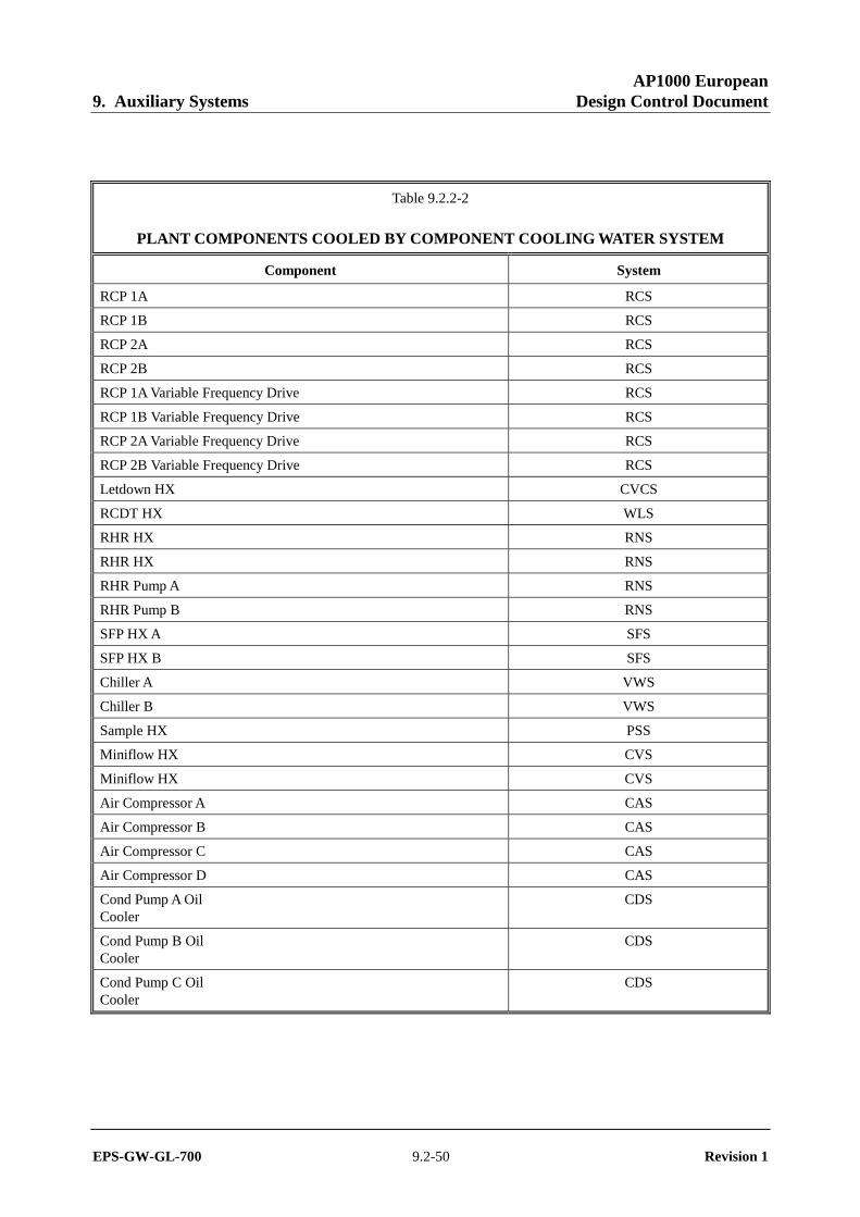
AP1000 European 9. Auxiliary Systems Design Control Document
EPS-GW-GL-700 9.2-50 Revision 1
Table 9.2.2-2
PLANT COMPONENTS COOLED BY COMPONENT COOLING WATER SYSTEM
Component System
RCP 1A RCS
RCP 1B RCS
RCP 2A RCS
RCP 2B RCS
RCP 1A Variable Frequency Drive RCS
RCP 1B Variable Frequency Drive RCS
RCP 2A Variable Frequency Drive RCS
RCP 2B Variable Frequency Drive RCS
Letdown HX CVCS
RCDT HX WLS
RHR HX RNS
RHR HX RNS
RHR Pump A RNS
RHR Pump B RNS
SFP HX A SFS
SFP HX B SFS
Chiller A VWS
Chiller B VWS
Sample HX PSS
Miniflow HX CVS
Miniflow HX CVS
Air Compressor A CAS
Air Compressor B CAS
Air Compressor C CAS
Air Compressor D CAS
Cond Pump A Oil Cooler
CDS
Cond Pump B Oil Cooler
CDS
Cond Pump C Oil Cooler
CDS

AP1000 European 9. Auxiliary Systems Design Control Document
EPS-GW-GL-700 9.2-51 Revision 1
Table 9.2.3-1
GUIDELINES FOR DEMINERALIZED WATER (MEASURED AT THE OUTLET OF THE DEMINERALIZED
WATER TREATMENT SYSTEM)
Parameters Normal Value Initiate Action
Specific conductivity, μS/cm at 77°F (25ºC) ≤ 0.1 ≤ 0.2
Active silica, ppb ≤ 10 ≤ 20
Total silica, ppb ≤ 50
Suspended solids, ppb ≤ 50
Aluminum, ppb ≤ 20
Calcium, ppb ≤ 5
Magnesium, ppb ≤ 5
Chloride, ppb ≤ 1
Sulfate, ppb ≤ 1
Total organic carbon, ppb ≤ 100
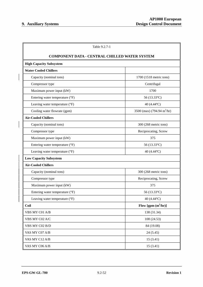
AP1000 European 9. Auxiliary Systems Design Control Document
EPS-GW-GL-700 9.2-52 Revision 1
Table 9.2.7-1
COMPONENT DATA - CENTRAL CHILLED WATER SYSTEM
High Capacity Subsystem
Water Cooled Chillers
Capacity (nominal tons) 1700 (1518 metric tons)
Compressor type Centrifugal
Maximum power input (kW) 1700
Entering water temperature (°F) 56 (13.33ºC)
Leaving water temperature (°F) 40 (4.44ºC)
Cooling water flowrate (gpm) 3500 (max) (794.94 m3/hr)
Air-Cooled Chillers
Capacity (nominal tons) 300 (268 metric tons)
Compressor type Reciprocating, Screw
Maximum power input (kW) 375
Entering water temperature (°F) 56 (13.33ºC)
Leaving water temperature (°F) 40 (4.44ºC)
Low Capacity Subsystem
Air-Cooled Chillers
Capacity (nominal tons) 300 (268 metric tons)
Compressor type Reciprocating, Screw
Maximum power input (kW) 375
Entering water temperature (°F) 56 (13.33ºC)
Leaving water temperature (°F) 40 (4.44ºC)
Coil Flow [gpm (m3/hr)]
VBS MY C01 A/B 138 (31.34)
VBS MY C02 A/C 108 (24.53)
VBS MY C02 B/D 84 (19.08)
VAS MY C07 A/B 24 (5.45)
VAS MY C12 A/B 15 (3.41)
VAS MY C06 A/B 15 (3.41)
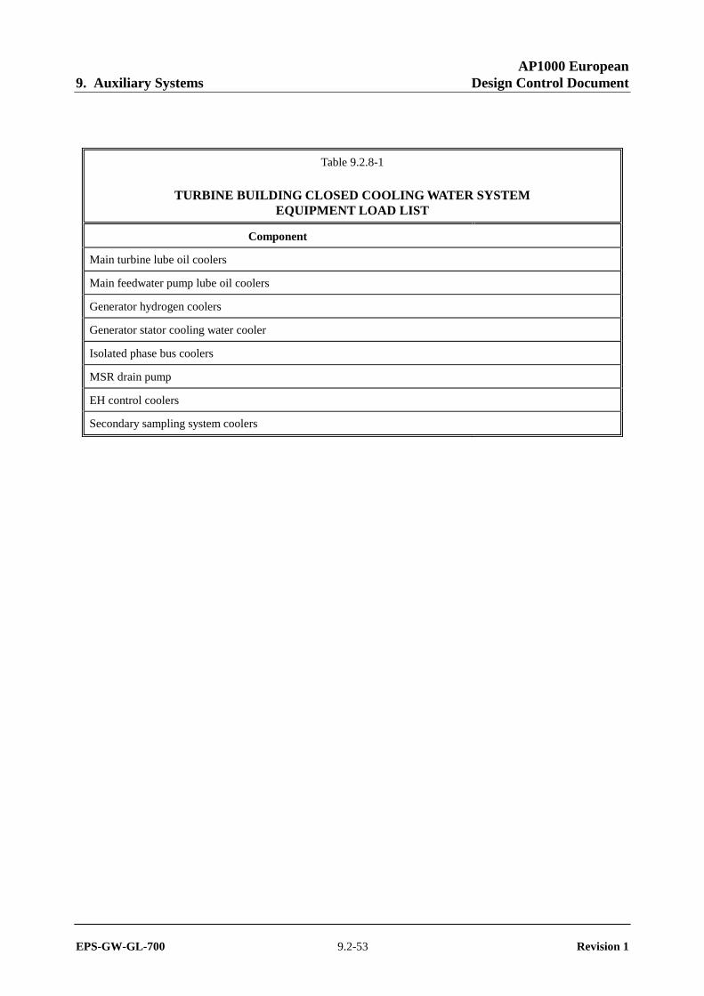
AP1000 European 9. Auxiliary Systems Design Control Document
EPS-GW-GL-700 9.2-53 Revision 1
Table 9.2.8-1
TURBINE BUILDING CLOSED COOLING WATER SYSTEM EQUIPMENT LOAD LIST
Component
Main turbine lube oil coolers
Main feedwater pump lube oil coolers
Generator hydrogen coolers
Generator stator cooling water cooler
Isolated phase bus coolers
MSR drain pump
EH control coolers
Secondary sampling system coolers

AP1000 European 9. Auxiliary Systems Design Control Document
EPS-GW-GL-700 9.2-54 Revision 1
Table 9.2.10-1
HOT WATER HEATING SYSTEM DESIGN DATA (NOMINAL VALUES)
Available Steam Supply
High pressure turbine extraction
Pressure (psia) 170 (1.172 MPa abs)
Enthalpy (Btu/lbm) 1087 (2.53×10⁶ joule/kg)
Temperature (°F) 368 (186.67ºC)
Auxiliary steam
Pressure (psia) 210 (1.448 MPa abs)
Enthalpy (Btu/lbm) 1199 (2.79×10⁶ joule/kg)
Temperature (°F) 386 (196.67ºC)
Heat Exchanger
Quantity 2
Type Shell and Tube – subcooled
Capacity (Btu/hr) 12,000,000 (3.52×10⁶ joule/sec)

AP1000 European 9. Auxiliary Systems Design Control Document
EPS-GW-GL-700 9.2-55 Revision 1
Figure 9.2.1-1 (Sheet 1 of 2)
Service Water System Figure represents system functional arrangement. Details internal to the system may Piping and Instrumentation Diagram differ as a result of implementation factors such as vendor-specific component requirements. (REF) SWS001
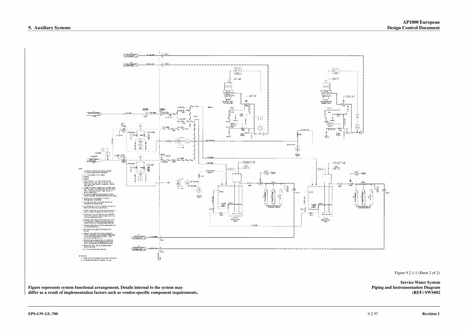
AP1000 European 9. Auxiliary Systems Design Control Document
EPS-GW-GL-700 9.2-57 Revision 1
Figure 9.2.1-1 (Sheet 2 of 2)
Service Water System Figure represents system functional arrangement. Details internal to the system may Piping and Instrumentation Diagram differ as a result of implementation factors such as vendor-specific component requirements. (REF) SWS002
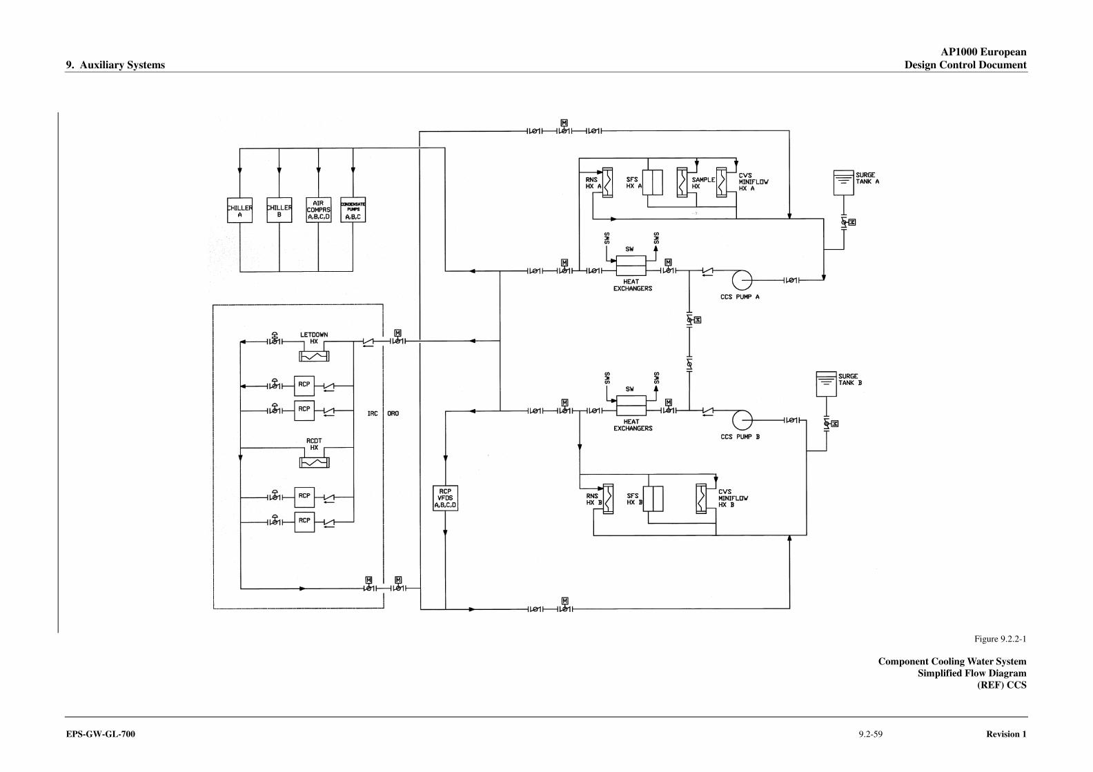
AP1000 European 9. Auxiliary Systems Design Control Document
EPS-GW-GL-700 9.2-59 Revision 1
Figure 9.2.2-1
Component Cooling Water System Simplified Flow Diagram
(REF) CCS
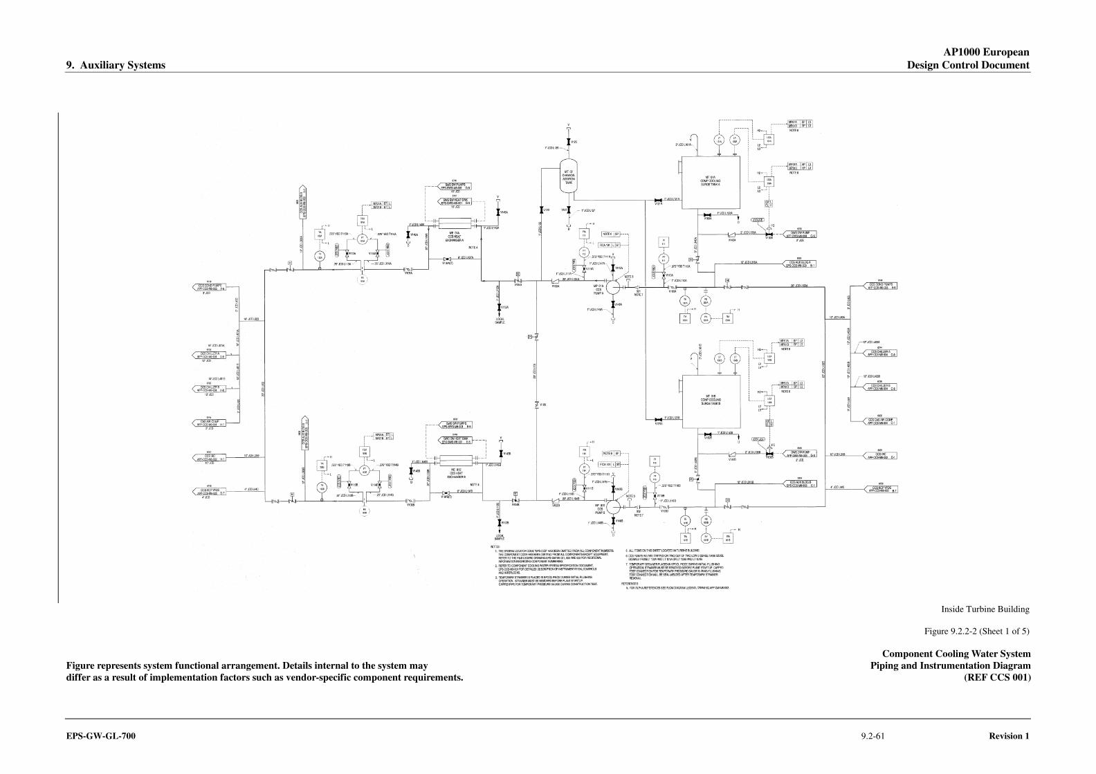
AP1000 European 9. Auxiliary Systems Design Control Document
EPS-GW-GL-700 9.2-61 Revision 1
Inside Turbine Building
Figure 9.2.2-2 (Sheet 1 of 5)
Component Cooling Water System Figure represents system functional arrangement. Details internal to the system may Piping and Instrumentation Diagram differ as a result of implementation factors such as vendor-specific component requirements. (REF CCS 001)
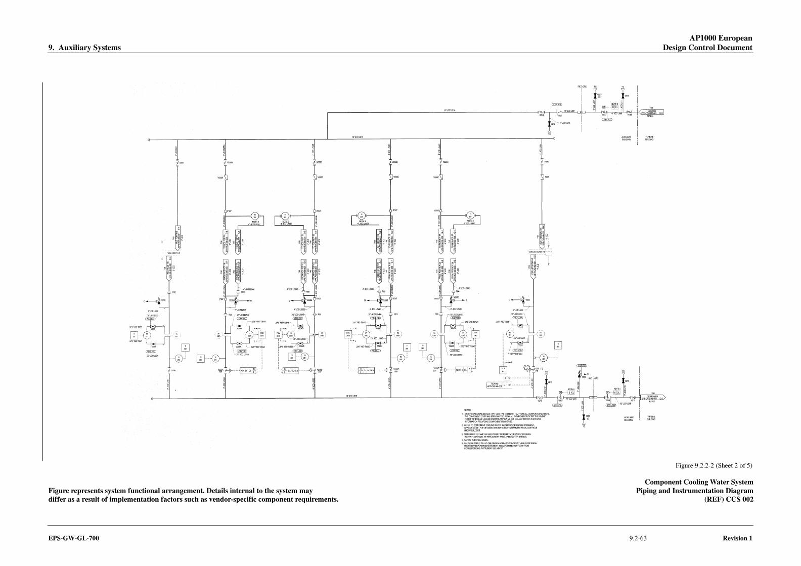
AP1000 European 9. Auxiliary Systems Design Control Document
EPS-GW-GL-700 9.2-63 Revision 1
Figure 9.2.2-2 (Sheet 2 of 5)
Component Cooling Water System Figure represents system functional arrangement. Details internal to the system may Piping and Instrumentation Diagram differ as a result of implementation factors such as vendor-specific component requirements. (REF) CCS 002
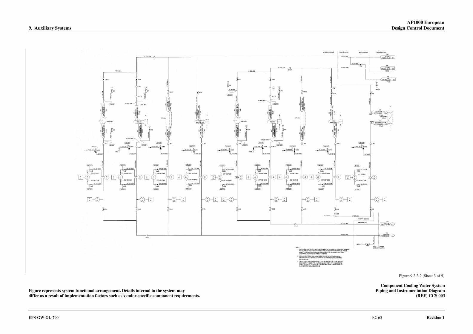
AP1000 European 9. Auxiliary Systems Design Control Document
EPS-GW-GL-700 9.2-65 Revision 1
Figure 9.2.2-2 (Sheet 3 of 5)
Component Cooling Water System Figure represents system functional arrangement. Details internal to the system may Piping and Instrumentation Diagram differ as a result of implementation factors such as vendor-specific component requirements. (REF) CCS 003

AP1000 European 9. Auxiliary Systems Design Control Document
EPS-GW-GL-700 9.2-67 Revision 1
Inside Turbine Building
Figure 9.2.2-2 (Sheet 4 of 5)
Component Cooling Water System Figure represents system functional arrangement. Details internal to the system may Piping and Instrumentation Diagram differ as a result of implementation factors such as vendor-specific component requirements. (REF) CCS 004
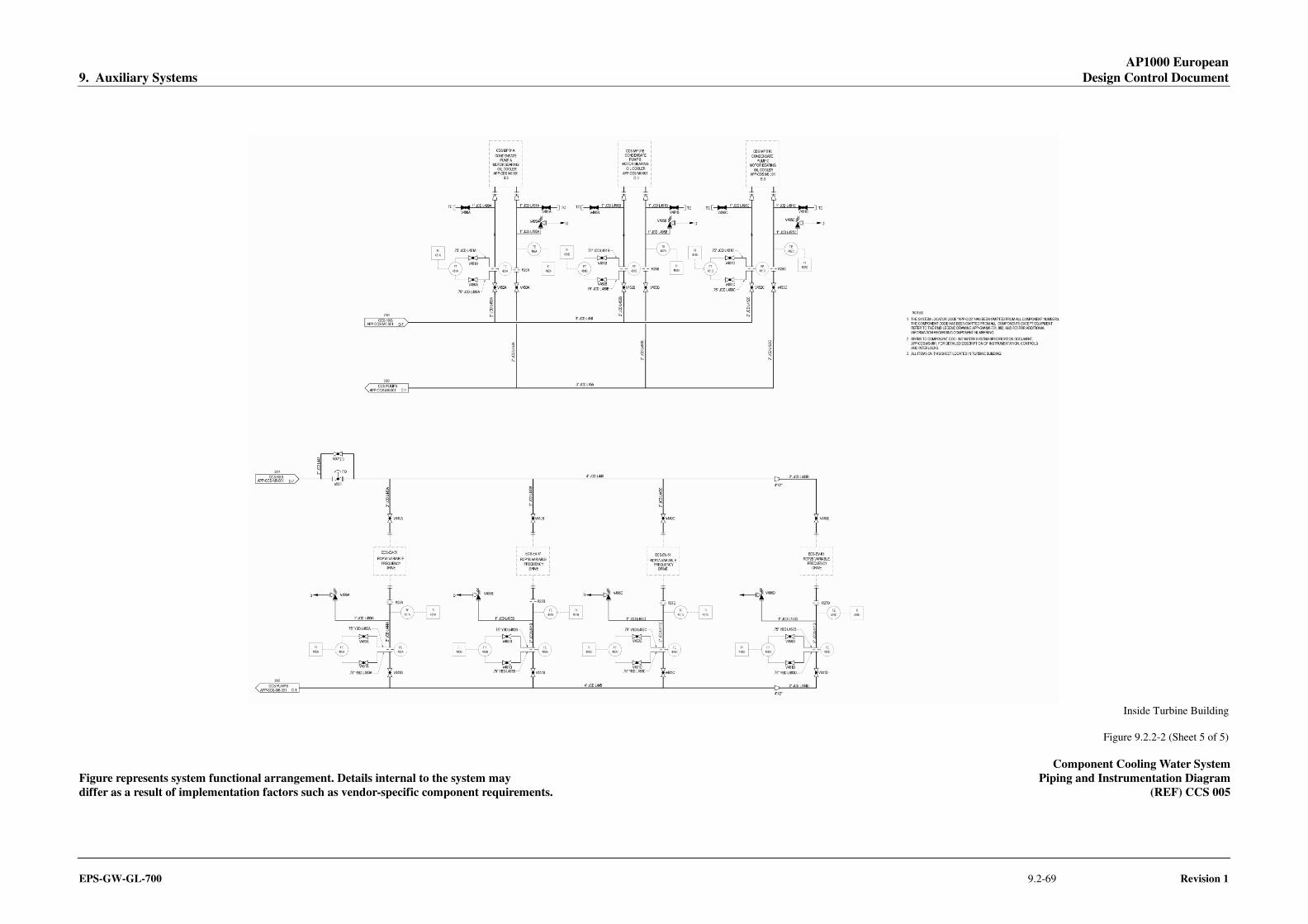
AP1000 European 9. Auxiliary Systems Design Control Document
EPS-GW-GL-700 9.2-69 Revision 1
Inside Turbine Building
Figure 9.2.2-2 (Sheet 5 of 5)
Component Cooling Water System Figure represents system functional arrangement. Details internal to the system may Piping and Instrumentation Diagram differ as a result of implementation factors such as vendor-specific component requirements. (REF) CCS 005

AP1000 European 9. Auxiliary Systems Design Control Document
EPS-GW-GL-700 9.2-71 Revision 1
Figure 9.2.4-1
Demineralized Water Transfer and Storage System Containment Isolation Provision
(REF) DWS 007

AP1000 European 9. Auxiliary Systems Design Control Document
EPS-GW-GL-700 9.2-73 Revision 1
Inside Auxiliary Building
Figure 9.2.7-1 (Sheet 1 of 4)
Central Chilled Water System Figure represents system functional arrangement. Details internal to the system may Piping and Instrumentation Diagram differ as a result of implementation factors such as vendor-specific component requirements. (REF) VWS 006

AP1000 European 9. Auxiliary Systems Design Control Document
EPS-GW-GL-700 9.2-75 Revision 1
Figure 9.2.7-1 (Sheet 2 of 4)
Central Chilled Water System Figure represents system functional arrangement. Details internal to the system may Piping and Instrumentation Diagram differ as a result of implementation factors such as vendor-specific component requirements. (REF) VWS 007

AP1000 European 9. Auxiliary Systems Design Control Document
EPS-GW-GL-700 9.2-77 Revision 1
Figure 9.2.7-1 (Sheet 3 of 4)
Central Chilled Water System Figure represents system functional arrangement. Details internal to the system may Piping and Instrumentation Diagram differ as a result of implementation factors such as vendor-specific component requirements. (REF) VWS 003

AP1000 European 9. Auxiliary Systems Design Control Document
EPS-GW-GL-700 9.2-79 Revision 1
Figure 9.2.7-1 (Sheet 4 of 4)
Figure represents system functional arrangement. Details internal to the system may High Capacity Subsystem Simplified Sketch differ as a result of implementation factors such as vendor-specific component requirements. (REF) VWS 004