65 gentry - kichler.com · figures 1, 2 and 3 are examples of different ways to mount the outlet...
TRANSCRIPT

65" GENTRY
INSTRUCTION MANUAL
Product images may vary slightly from actual product.

TABLE OF CONTENTS
SAFETY RULES.......................................................................... 4
5
5
6
7
10
11
13
14
14
TOOLS REQUIRED....................................................................
PACKAGE CONTENTS.............................................................
MOUNTING OPTIONS.............................................................
HANGING THE FAN..................................................................
INSTALLATION OF SAFETY SUPPORT..........................
ELECTRICAL CONNECTIONS.............................................
FINISHING THE INSTALLATION........................................
INSTALLING THE LIGHT PLATE........................................
INSTALLING THE LED LIGHT KITAND GLASS SHADE ASSEMBLY......................................15
16
17
18
19
20
21
CONTROL SYSTEM SET-UP...............................................
BUTTON INSTRUCTION........................................................
INSTALLING THE WALL CONTROLSYSTEM WALL PLATE...........................................................
OPERATION INSTRUCTIONS............................................
TROUBLESHOOTING............................................................
65" GENTRY | 3
ATTACHING THE FAN BLADES..........................................
SENSORLESS DC CONTROL PAIRING PROCEDURES...........................................................................

4 | KICHLER.COM
SAFETY RULES
WARNING: FOR CANADA, THIS FAN MUST BE SECURED DIRECTLY TO THE BUILDING STRUCTURE / CEILING JOIST. DON'T SECURE THIS FAN TO AN OUTLET BOX.
1. To reduce the risk of electric shock, insure electricity has been turned off at the circuit breaker or fuse box before beginning.
2. All wiring must be in accordance with the National Electrical Code and local electrical codes. Electrical installation should be performed by a qualified licensed electrician.
3. WARNING: Not suitable for use with solid-state speed controls.
4. WARNING: To reduce the risk of fire, electric shock, or personal injury, mount to outlet box marked "acceptable for fan support of 22.7 kg (50 lbs.) or less" and use mounting screws provided with the outlet box. Most outlet boxes commonly used for the support of light fixtures are not acceptable for fan support and may need to be replaced. Due to the complexity of the installation of this fan, a qualified licensed electrician is strongly recommended.
WARNING: TO REDUCE THE RISK OF FIRE, ELECTRIC SHOCK OR PERSONAL INJURY, MOUNT FAN TO OUTLET BOX MARKED "ACCEPTABLE FOR FAN SUPPORT".
5. The outlet box and support structure must be securely mounted and capable of reliably supporting a minimum of 50 pounds. Use only CUL Listed outlet boxes marked "FOR FAN SUPPORT".
6. The fan must be mounted with a minimum of 7 feet clearance from the trailing edge of the blades to the floor.
7. To operate the reverse function on this fan, press the reverse button while the fan is running.
8. Avoid placing objects in the path of the blades.
9. To avoid personal injury or damage to the fan and other items, be cautious when working around or cleaning the fan.
10. Do not use water or detergents when cleaning the fan or fan blades. A dry dust cloth or lightly dampened cloth will be suitable for most cleaning.
11. After marking electrical connections, spliced conductors should be turned upward and pushed carefully up into outlet box. The wires should be spread apart with the grounded conductor and the equipment-grounding conductor on one side of the outlet box.
12. Electrical diagrams are reference only. Light kits that are not packed with the fan must be CUL Listed and marked suitable for use with the model fan you are installing. Switches must be CUL General Use Switches. Refer to the Instructions packaged with the light kits and switches for proper assembly.
WARNING: TO REDUCE THE RISK OF PERSONAL INJURY, DO NOT BEND THE BLADE BRACKETS (ALSO REFERRED TO AS FLANGES) DURING ASSEMBLY OR AFTER INSTALLATION. DO NOT INSERT OBJECTS IN THE PATH OF THE BLADES.
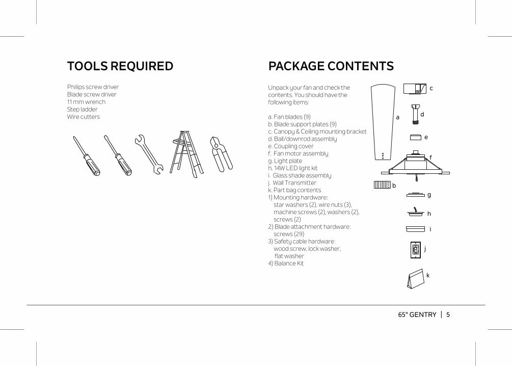
TOOLS REQUIRED
Philips screw driverBlade screw driver11 mm wrenchStep ladderWire cutters
PACKAGE CONTENTS
i
j
k
f
g
h
b
c
d
e
Unpack your fan and check the contents. You should have the following items:
a. Fan blades (9) b. Blade support plates (9)c. Canopy & Ceiling mounting bracketd. Ball/downrod assemblye. Coupling coverf. Fan motor assemblyg. Light plateh. 14W LED light kit i. Glass shade assembly j. Wall Transmitterk. Part bag contents1) Mounting hardware: star washers (2), wire nuts (3),
machine screws (2), washers (2), screws (2)
2) Blade attachment hardware: screws (29)
3) Safety cable hardware: wood screw, lock washer, flat washer4) Balance Kit
a
65" GENTRY | 5

6 | KICHLER.COM
If there isn't an existing UL (cUL for Canadian Installation) listed mounting box, then read the following instructions. Disconnect the power by removing fuses or turning off circuit breakers.
Secure the outlet box directly to the building structure. Use appropriate fasteners and building materials. The outlet box and its support must be able to fully support the moving weight of the fan (at least 50 lbs). Do not use plastic outlet boxes.
Figures 1, 2 and 3 are examples of different ways to mount the outlet box.
NOTE: If you are installing the ceiling fan on a sloped (vaulted) ceiling, you may need a longer downrod to maintain proper clearance between the tip of the blade and the ceiling. A minimum clearance of 12" is suggested for optimal operation.
NOTE: Depending on the location you have selected for installation, you may need to purchase and install a "Joist Hanger" for the support of the outlet box. Make sure the joist hanger you purchase has been designed for use with ceiling fans. (Fig. 4)
MOUNTING OPTIONS
Fig. 1
Outlet box
Outlet boxFig. 2Provide strong
support
Recessedoutlet box Ceiling
mountingplate
Fig. 3
ANGLED CEILINGMAXIMUM 20° ANGLE
Outlet boxFig. 4
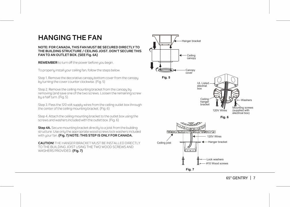
Fig. 5
Fig. 6
Fig. 7
Hanger bracket
Ceiling canopy
Canopycover
HANGING THE FANNOTE: FOR CANADA, THIS FAN MUST BE SECURED DIRECTLY TO THE BUILDING STRUCTURE / CEILING JOIST. DON'T SECURE THIS FAN TO AN OUTLET BOX. (SEE Fig. 6A)
REMEMBER to turn off the power before you begin.
To properly install your ceiling fan, follow the steps below.
Step 1. Remove the decorative canopy bottom cover from the canopy by turning the cover counter clockwise. (Fig. 5)
Step 2. Remove the ceiling mounting bracket from the canopy by removing (and save one of the two screws. Loosen the remaining screw by a half turn. (Fig. 5)
Step 3. Pass the 120 volt supply wires from the ceiling outlet box through the center of the ceiling mounting bracket. (Fig. 6)
Step 4. Attach the ceiling mounting bracket to the outlet box using the screws and washers included with the outlet box. (Fig. 6)
Step 4A. Secure mounting bracket directly to a joist from the building structure. Use only the appropriate wood screws lock washers included with your fan. (Fig. 7) NOTE: THIS STEP IS ONLY FOR CANADA.
CAUTION! THE HANGER BRACKET MUST BE INSTALLED DIRECTLY TO THE BUILDING JOIST USING THE TWO WOOD SCREWS AND WASHERS PROVIDED. (Fig. 7)
65" GENTRY | 7
120V Wires
Hanger bracketCeiling joist
#10 Wood screwsLock washers
120V Wires
Ceiling hangerbracket
Mounting screws (supplied with electrical box)
UL Listed electrial box
Washers
8 | KICHLER.COM
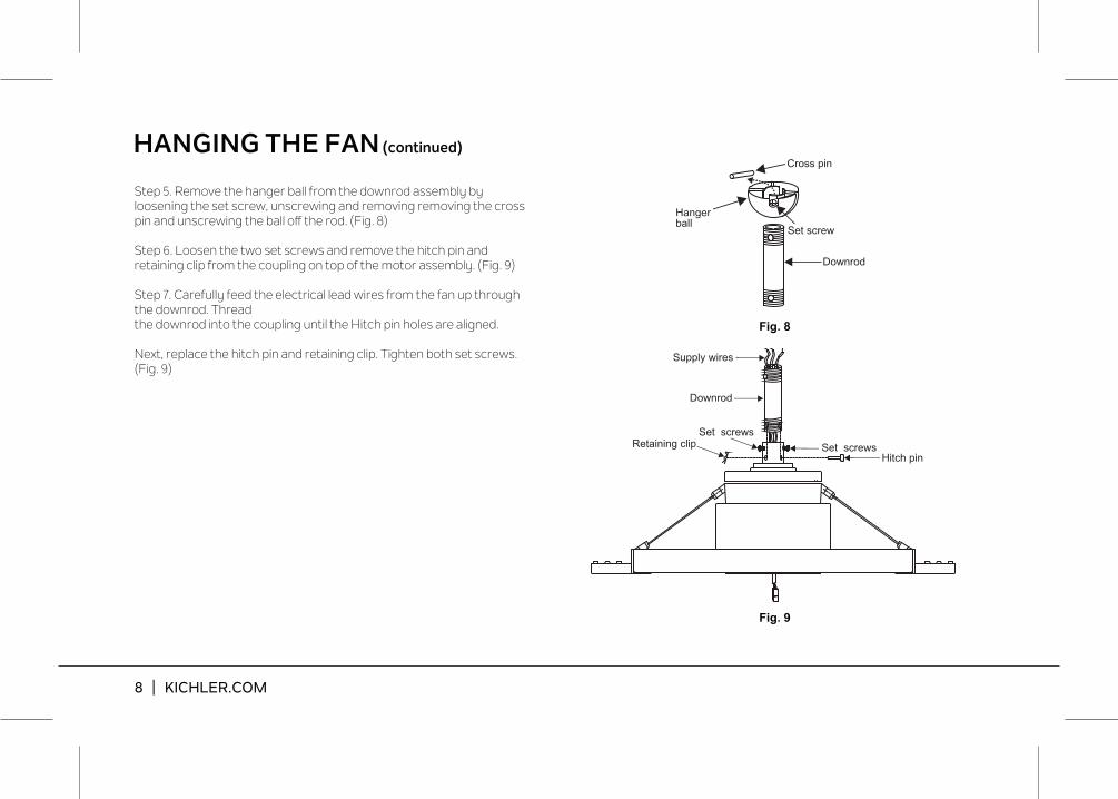
Step 5. Remove the hanger ball from the downrod assembly by loosening the set screw, unscrewing and removing removing the cross pin and unscrewing the ball off the rod. (Fig. 8)
Step 6. Loosen the two set screws and remove the hitch pin and retaining clip from the coupling on top of the motor assembly. (Fig. 9)
Step 7. Carefully feed the electrical lead wires from the fan up through the downrod. Threadthe downrod into the coupling until the Hitch pin holes are aligned.
Next, replace the hitch pin and retaining clip. Tighten both set screws. (Fig. 9)
HANGING THE FAN (continued)
Fig. 8
Fig. 9
Downrod
Cross pin
Hangerball
Set screw
Supply wires
Downrod
Hitch pinRetaining clip Set screws
Set screws
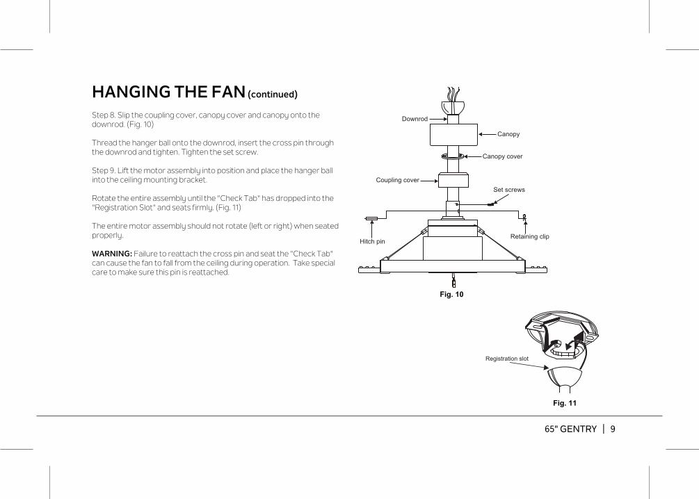
Fig. 10
Fig. 11
HANGING THE FAN (continued)
Step 8. Slip the coupling cover, canopy cover and canopy onto the downrod. (Fig. 10)
Thread the hanger ball onto the downrod, insert the cross pin through the downrod and tighten. Tighten the set screw.
Step 9. Lift the motor assembly into position and place the hanger ball into the ceiling mounting bracket.
Rotate the entire assembly until the "Check Tab" has dropped into the "Registration Slot" and seats firmly. (Fig. 11)
The entire motor assembly should not rotate (left or right) when seated properly.
WARNING: Failure to reattach the cross pin and seat the "Check Tab" can cause the fan to fall from the ceiling during operation. Take special care to make sure this pin is reattached.
Registration slot
Downrod
Canopy
Canopy cover
Set screws
Hitch pinRetaining clip
Coupling cover
65" GENTRY | 9
10 | KICHLER.COM
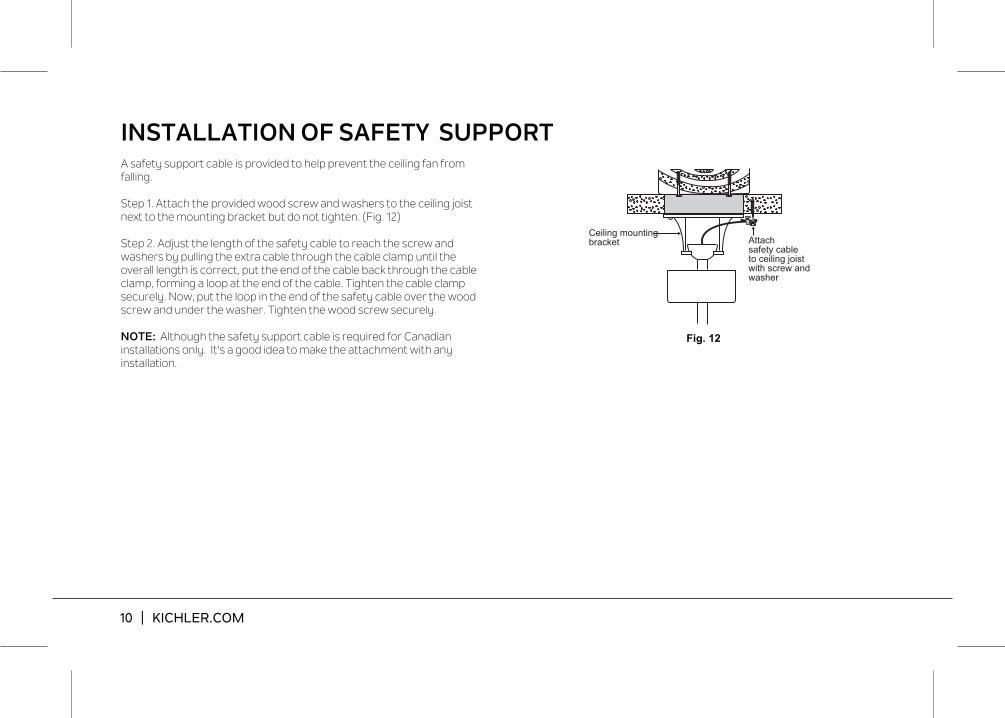
A safety support cable is provided to help prevent the ceiling fan from falling.
Step 1. Attach the provided wood screw and washers to the ceiling joist next to the mounting bracket but do not tighten. (Fig. 12)
Step 2. Adjust the length of the safety cable to reach the screw and washers by pulling the extra cable through the cable clamp until the overall length is correct, put the end of the cable back through the cable clamp, forming a loop at the end of the cable. Tighten the cable clamp securely. Now, put the loop in the end of the safety cable over the wood screw and under the washer. Tighten the wood screw securely.
NOTE: Although the safety support cable is required for Canadian installations only. It's a good idea to make the attachment with anyinstallation.
Fig. 12
Ceiling mounting bracket Attach
safety cableto ceiling joistwith screw andwasher
INSTALLATION OF SAFETY SUPPORT
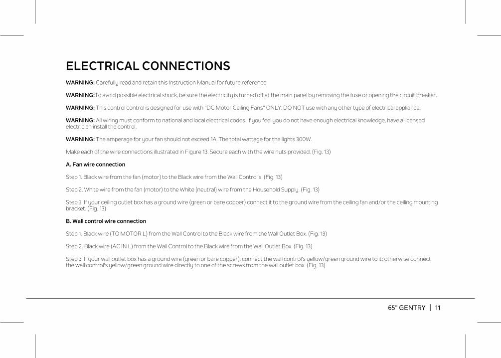
ELECTRICAL CONNECTIONSWARNING: Carefully read and retain this Instruction Manual for future reference.
WARNING:To avoid possible electrical shock, be sure the electricity is turned off at the main panel by removing the fuse or opening the circuit breaker.
WARNING: This control control is designed for use with "DC Motor Ceiling Fans" ONLY. DO NOT use with any other type of electrical appliance.
WARNING: All wiring must conform to national and local electrical codes. If you feel you do not have enough electrical knowledge, have a licensed electrician install the control.
WARNING: The amperage for your fan should not exceed 1A. The total wattage for the lights 300W.
Make each of the wire connections illustrated in Figure 13. Secure each with the wire nuts provided. (Fig. 13)
A. Fan wire connection
Step 1. Black wire from the fan (motor) to the Black wire from the Wall Control's. (Fig. 13)
Step 2. White wire from the fan (motor) to the White (neutral) wire from the Household Supply. (Fig. 13)
Step 3. If your ceiling outlet box has a ground wire (green or bare copper) connect it to the ground wire from the ceiling fan and/or the ceiling mounting bracket. (Fig. 13)
B. Wall control wire connection
Step 1. Black wire (TO MOTOR L) from the Wall Control to the Black wire from the Wall Outlet Box. (Fig. 13)
Step 2. Black wire (AC IN L) from the Wall Control to the Black wire from the Wall Outlet Box. (Fig. 13)
Step 3. If your wall outlet box has a ground wire (green or bare copper), connect the wall control's yellow/green ground wire to it; otherwise connect the wall control's yellow/green ground wire directly to one of the screws from the wall outlet box. (Fig. 13)
65" GENTRY | 11

12 | KICHLER.COM
Fig. 13
Black White
Black
Black
Ground conductor
Outlet box
Wall outlet box
Yellow/green ground
BlackBlackBlack
Black
Bla
ck
Whi
te
Gre
en
SUPPLY CIRCUIT

Fig. 14
Outlet box
Ceiling mountingbracket
Canopy
Canopy cover
Screws
Screws
Step 1. Tuck all the connections neatly into the ceiling outlet box.
Step 2. Slide the canopy up to the mounting bracket and place one of the key hole slots over the mounting screw on the mounting bracket. Rotate the canopy until the screw head locks in place at the narrow section of the key hole. See figure 14.
Step 3. Align the remaining circular hole on the canopy with the remaining hole on the Ceiling Mounting Bracket. Insert and tighten the mounting screw you removed earlier and the mounting screw from Step 2 above. Now, attach the canopy cover to the mounting screw heads by inserting the screw heads into the bottom side of the canopy cover and rotating the cover clockwise.
NOTE: Adjust the canopy screws as necessary until the canopy and canopy cover are snug. (Fig. 14)
WARNING: Make sure the "Check Tab" at the bottom of the hanger bracket is properly seated in the "Registration Slot" on the side of the hanger ball before attaching the canopy to the bracket. Failure to properly seat the "Check Tab" could damage the electrical wires when to ceiling fan blade direction is changed while the fan is running.
FINISHING THE INSTALLATION
65" GENTRY | 13
14 | KICHLER.COM
Fig. 16
Fig. 15
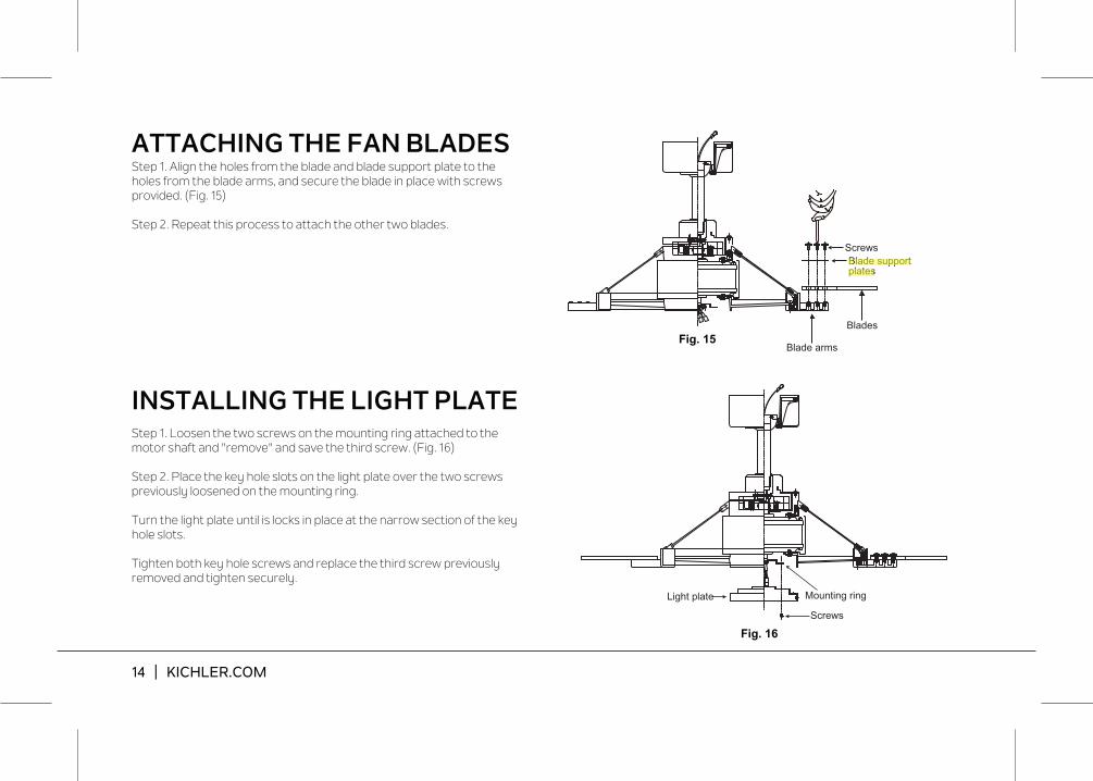
INSTALLING THE LIGHT PLATEStep 1. Loosen the two screws on the mounting ring attached to the motor shaft and "remove" and save the third screw. (Fig. 16)
Step 2. Place the key hole slots on the light plate over the two screws previously loosened on the mounting ring.
Turn the light plate until is locks in place at the narrow section of the key hole slots.
Tighten both key hole screws and replace the third screw previously removed and tighten securely.
Blades
Blade arms
ScrewsBlade supportplates
ATTACHING THE FAN BLADESStep 1. Align the holes from the blade and blade support plate to the holes from the blade arms, and secure the blade in place with screws provided. (Fig. 15)
Step 2. Repeat this process to attach the other two blades.
Light plate Mounting ring
Screws

65" GENTRY | 15
Fig. 17
Fig. 18
INSTALLING THE LED LIGHT KITAND GLASS SHADE ASSEMBLYNOTE: Before starting installation, disconnect the power by turning off the circuit breaker or removing the fuse at fuse box.
Step 1. Loosen the three mounting screws on the inside of the LED light kit. (Fig.17)
Step 2. While holding the LED light kit under the fan motor, make the wire connections: (Fig. 17)- Red to white - Black to black
Step 3. Tuck the connections neatly into the light plate. Place the key holes on the LED light kit over the 2 screws previously loosened from the light plate, turn the LED light kit until it locks in place at the narrow section of the key holes. Secure by tightening all three screws. (Fig.17)
Step 4. Raise the glass shade against the light plate and Secure by tightening all three screws. (Fig. 18)
Wire connectors
LED light kit
Light plate
ScrewsGlass shadeassembly
Screws
16 | KICHLER.COM
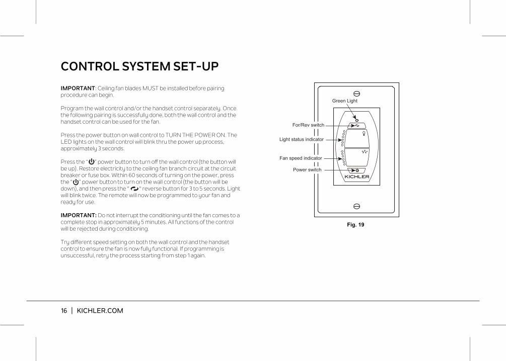
Fig. 19
CONTROL SYSTEM SET-UP
Green Light
For/Rev switch
Light status indicator
Fan speed indicator
Power switch
IMPORTANT: Ceiling fan blades MUST be installed before pairing procedure can begin.
Program the wall control and/or the handset control separately. Once the following pairing is successfully done, both the wall control and the handset control can be used for the fan.
Press the power button on wall control to TURN THE POWER ON. The LED lights on the wall control will blink thru the power up process, approximately 3 seconds.
Press the “ ” power button to turn off the wall control (the button will be up). Restore electricity to the ceiling fan branch circuit at the circuit breaker or fuse box. Within 60 seconds of turning on the power, press the “ ” power button to turn on the wall control (the button will be down), and then press the " " reverse button for 3 to 5 seconds. Light will blink twice. The remote will now be programmed to your fan and ready for use.
IMPORTANT: Do not interrupt the conditioning until the fan comes to a complete stop in approximately 5 minutes. All functions of the control will be rejected during conditioning.
Try different speed setting on both the wall control and the handset control to ensure the fan is now fully functional. If programming is unsuccessful, retry the process starting from step 1 again.

65" GENTRY | 17
Fig. 20
LED Indicator Red LED: Transmitter signal indicator. When RF signal is sending, the red light will illuminate.Green LED: To show the Forward and Reverse indicator.
ON/OFF button " "ON: Turn on the power.OFF: Turn off the power.
Reverse button " "When the fan is running, press and release the Reverse button one time, the fan will change operating direction.Downflow: Green indicator LED will be off.Reverse: Green indicator LED will be on.
Light button " "Press and release the Light button for light ON/OFF control.Light indicator LEDs will show current light status. If the light kit is OFF, the Light indicator LEDs are also all off. Press AND HOLD the light button for more than 1 second and the light kit will begin dimming. Light indicator LED will show the change in light level status. The light level cycles from bright to dim and back to bright when the light button is held.
Fan control " "Press and release the Fan speed button for Fan ON/OFF control.Fan indicator LED will illustrate the current fan speed. If the fan is OFF, the fan speed indicator LEDs will also be OFF. Press and hold Fans speed button for more than 1second to begin adjusting the fan speeds. The indicator LEDs will shows the current speed level. The fan speed adjustments adjust in a repeat cycle when the speed button is held down. The speeds adjust from High to Low, then back up to High.
BUTTON INSTRUCTION
18 | KICHLER.COM
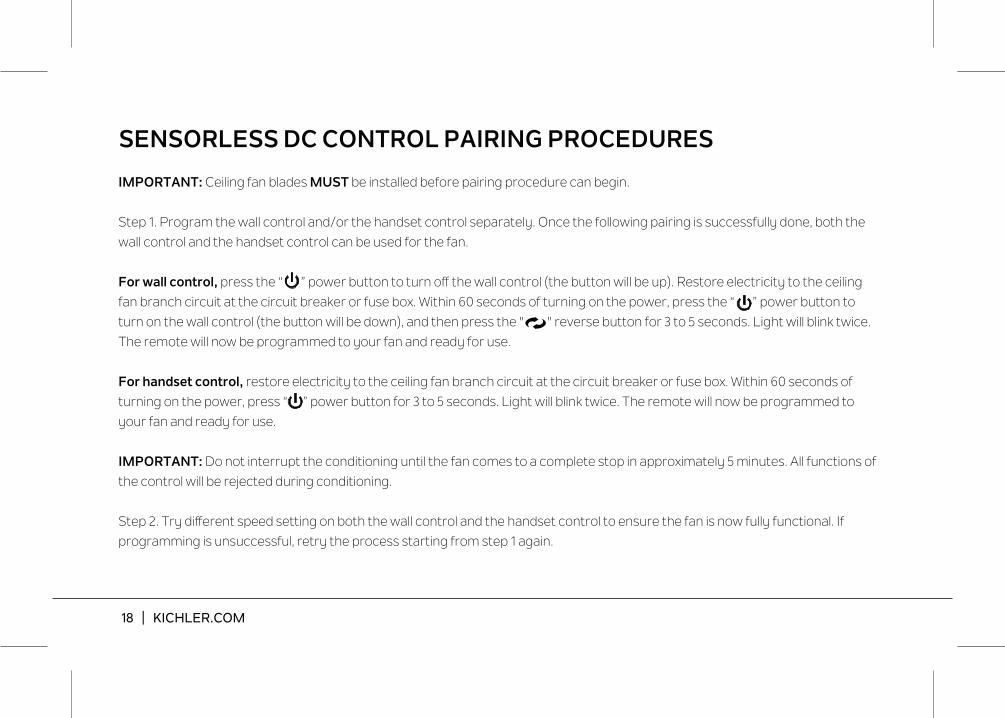
SENSORLESS DC CONTROL PAIRING PROCEDURES
IMPORTANT: Ceiling fan blades MUST be installed before pairing procedure can begin.
Step 1. Program the wall control and/or the handset control separately. Once the following pairing is successfully done, both the wall control and the handset control can be used for the fan.
For wall control, fan branch circuit at the circuit breaker or fuse box. Within 60 seconds of turning on the power, press the “ ” power button to turn on the wall control (the button will be down), and then press the " " reverse button for 3 to 5 seconds. Light will blink twice. The remote will now be programmed to your fan and ready for use.
For handset control, restore electricity to the ceiling fan branch circuit at the circuit breaker or fuse box. Within 60 seconds of turning on the power, press “ ” power button for 3 to 5 seconds. Light will blink twice. The remote will now be programmed to your fan and ready for use.
IMPORTANT: Do not interrupt the conditioning until the fan comes to a complete stop in approximately 5 minutes. All functions of the control will be rejected during conditioning.
If programming is unsuccessful, retry the process starting from step 1 again.

65" GENTRY | 19
Fig. 21
Select a location to install the Wall Control System Transmitter and Wall Plate.
REMEMBER also this should state that the control is not to be mounted outdoors. You can safely use the transmitter outdoors but it should be mounted indoors away from excess heat and away from contact with water or humidity.
Install the wall plate using an existing wall switch outlet box. Make sure the electrical power is TURNED OFF at the main panel before continuing.
If your ceiling outlet box has a ground wire (green or bare copper) connect it to the ground wire from the wall switch and/or the ceiling mounting bracket and push back inside the outlet box.
Install the wall plate on the existing wall outlet box using the screws provided. (Fig. 21)
After installing the wall anchors, attached the wall plate with the mounting screws to finish the installation.
INSTALLING THE WALL CONTROL SYSTEM WALL PLATE
Screws
Outlet box
Screws
Wall plateSwitch
20 | KICHLER.COM
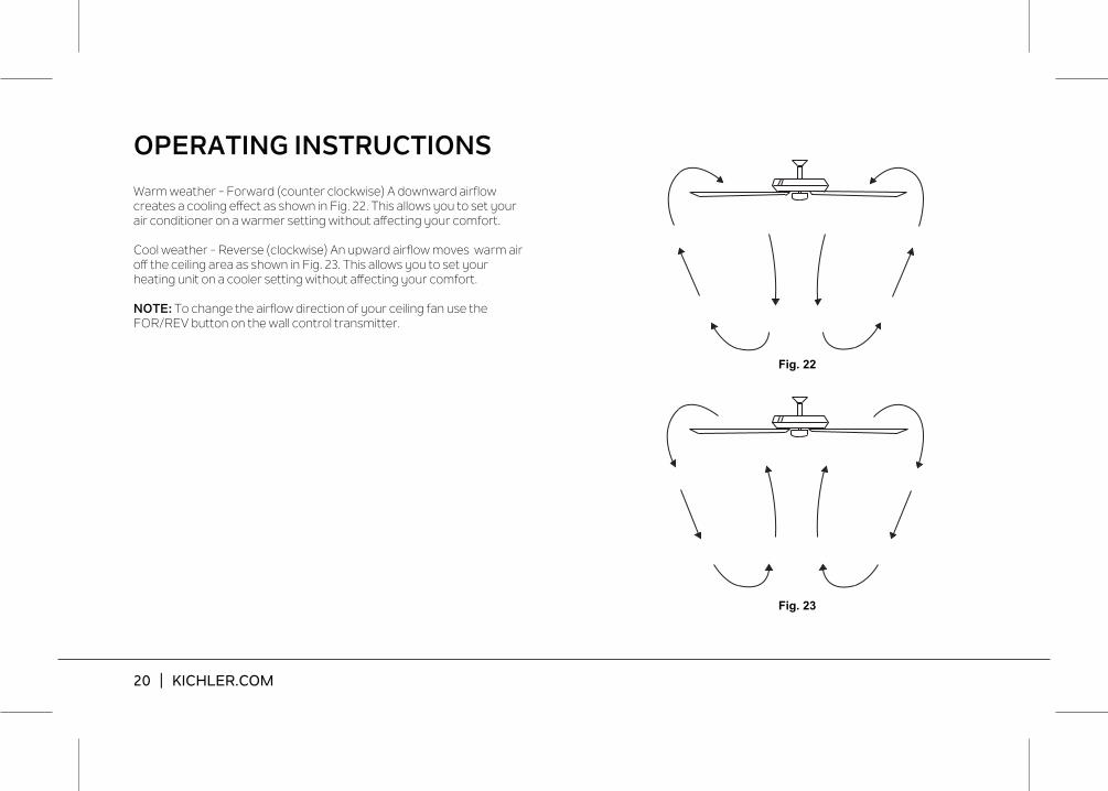
Fig. 22
Fig. 23
Warm weather - Forward (counter clockwise) A downward airflow creates a cooling effect as shown in Fig. 22. This allows you to set your air conditioner on a warmer setting without affecting your comfort. Cool weather - Reverse (clockwise) An upward airflow moves warm air off the ceiling area as shown in Fig. 23. This allows you to set your heating unit on a cooler setting without affecting your comfort.
NOTE: To change the airflow direction of your ceiling fan use the FOR/REV button on the wall control transmitter.
OPERATING INSTRUCTIONS

65" GENTRY | 21
Problem
Fan will not start.
Fan sounds noisy.
Fan wobble.
Remote control malfunction.
Solution
1. Check circuit fuses or breakers.2. Check all electrical connections to insure proper contact. CAUTION: Make sure the main power is OFF when checking any electrical connection.
1. Make sure all motor housing screws are snug.2. Make sure the screws that attach the fan blade brackets to the motor are tight.3. Make sure wire nut connections are not rubbing against each other or the interior wall of the switch housing. CAUTION:
Make sure main power is off.4. Allow a 24-hour "breaking-in" period. Most noise associated with a new fan disappear during this time.5. If using an optional light kit, make sure the screws securing the glassware are tight. Make sure the light bulbs are not
touching any other component.6. Do not connect this fan to wall mounted variable speed control(s). they are not compatible with ceiling fan motors or
remote controls.7. Make sure the upper canopy is a short distance from the ceiling. It should not touch the ceiling.
1. Check that all blade and blade arm screws are secure.2. Most fan wobbling problems are caused when blade levels are unequal. Check this level by selecting a point on the ceiling
above the tip of one of the blades. Measure this distance. Rotate the fan until the next blade is positioned for measurement. Repeat for each blade. The distance deviation should be equal within 1/8".
3. If the blade wobble is still noticeable, interchanging two adjacent (side by side) blades can redistribute the weight and possibly result in smoother operation.
1. Ceiling Fans with remote control systems CAN NOT be operated in conjunction with any other control system EXCEPT a basic On/Off wall switch, if desired.
TROUBLESHOOTING

www.kichler.com
KICHLER® LIGHTING
7711 EAST PLEASANT VALLEY ROAD P.O. BOX 318010
CLEVELAND, OHIO 44131-8010
CUSTOMER SERVICE 866.558.5706
8:30 AM TO 5:00 PM EST, MONDAY - FRIDAY