44 hrg injection
TRANSCRIPT
________________________________________________________________________
Choice of Technological Regimes of a Blast FurnaceOperation with Injection of Hot Reducing Gases
A.Babich, H.W.Gudenau, A.Formoso1, K.Mavrommatis, C.Froehling, L.Garcia1

2
AbstractInjection rate of fossil fuels is limited because of drop in the flame temperature in theraceway and problems in the deadman region and the cohesive zone. The next stepfor further considerable coke saving, clean deadman as well as increase in blastfurnace productivity and minimizing the environmental impact due to a decrease incarbon dioxide emission would be injection of hot reducing gases (HRG) which areproduced by low grade coal gasification or top gas regenerating. Use of HRG incombination with high PCI rate and oxygen enrichment in the blast could allow tokeep and to increase the competitiveness of the blast furnace process.
Calculations using a mathematical model show that the HRG injection in combinationwith PC and enriching blast with oxygen may provide an increase in PC rate up to300-400 kg/tHM and a rise in the furnace productivity by 40-50%. Blast furnaceoperation with full oxygen blast (100% of process oxygen with the exception for thehot blast) is possible when HRG is injected.

3
1. IntroductionOne of the largest global challenges in this age is the preservation of the
environment. The world-wide energy consumption is approx. 9.8 *1018 J per year, the
CO2 -emissions causing the greenhouse effect and coming out of human activities
are approx. 860 Mt/a /1/. Regarding the agreement of Kyoto/2/ the steel industry
must find a compromise between environmental compatibility, economy, saving of
resources and supply guarantee. The steel industriy is responsible for approx. 5 % of
the world-wide energy consumption/3/ (in Germany about 10%) and therefore in the
future has to deal more and more with the preservation of resources as well as the
lowering of CO2-emissions.
Steel work and rolling
mill14%
Blast furnace and sinter
plant72%Power plant
and others14%
Figure 1: Structure of energy consumption in an integrated steel work /4/
Currently approx. 95 % of the pig iron is made by blast furnace process, which in
spite of modern technologies contributes considerably to the high energy
consumption and environmental impact.
The blast furnace, sinter plant and coke oven plant consume 70-75% of the entire
energy consumption of an integrated steelwork (Figure 1). In consideration of the
linked energy, this value is in the range of 11-12 GJ /t HM /4/ The main part of the
required fuels is covered by metallurgical coke, which makes up 40-50% of the total
fuel /5/. By production of 1 t coke is released about 4150 kg of CO2./6/
Apart from the ecological consequences, coke causes a majority of production costs
of the pig iron. But despite all ecological and economical problems resulting from the
coke use, the blast furnace route remains the most efficient way to produce crude
steel. Only about 5% of the primary metal is manufactured by alternative steelmaking
4
processes such as direct- and smelting-reduction methods /7/. Thus the lowering of
coke consumption and total energy consumption at the blast furnace process is of
large importance not only from aspects of environmental protection, but also from
economic regard.
Previous Development:
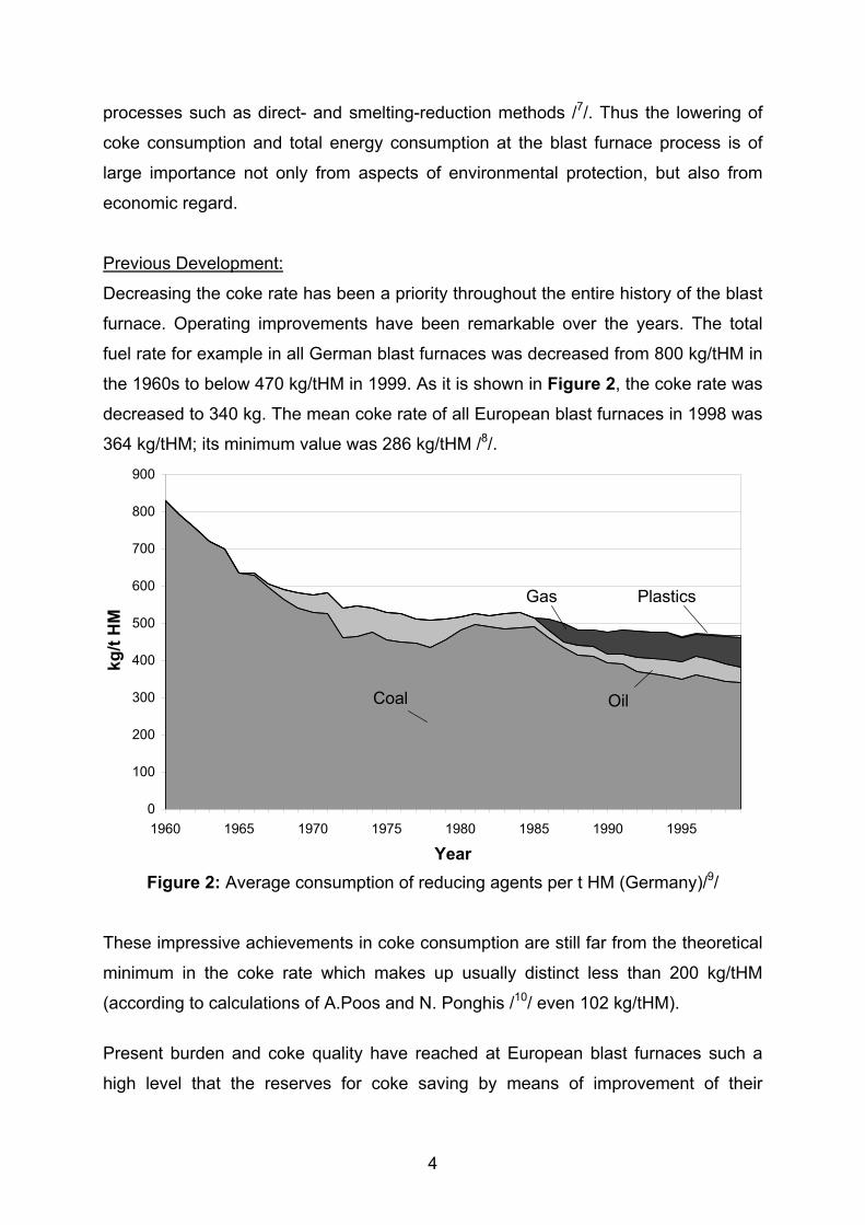
Decreasing the coke rate has been a priority throughout the entire history of the blast
furnace. Operating improvements have been remarkable over the years. The total
fuel rate for example in all German blast furnaces was decreased from 800 kg/tHM in
the 1960s to below 470 kg/tHM in 1999. As it is shown in Figure 2, the coke rate was
decreased to 340 kg. The mean coke rate of all European blast furnaces in 1998 was
364 kg/tHM; its minimum value was 286 kg/tHM /8/.
0
100
200
300
400
500
600
700
800
900
1960 1965 1970 1975 1980 1985 1990 1995
Year
kg/t
HM
Coal
PlasticsGas
Oil
Figure 2: Average consumption of reducing agents per t HM (Germany)/9/
These impressive achievements in coke consumption are still far from the theoretical
minimum in the coke rate which makes up usually distinct less than 200 kg/tHM
(according to calculations of A.Poos and N. Ponghis /10/ even 102 kg/tHM).
Present burden and coke quality have reached at European blast furnaces such a
high level that the reserves for coke saving by means of improvement of their

5
preparation are almost exhausted. According to the statistical study, only about 10%
of coke rate variation are explained by coke and ore burden properties /8/.
Partial replacement of coke by other fuels has been within the last two decades the
main way of coke saving. Auxiliary fuels as natural gases (NG), oil, pulverized coal
(PC) and occasionally coke oven gases and organic wastes are injected via the
tuyeres. Coke consumption of about 286-320 kg/tHM have been achieved at some
blast furnaces by the PC injection of 170-200 kg/tHM /11/12/13/.
Consumption of fossil fuels injected via the tuyeres is limited by their endothermic
effect and by the oxidizing potential of the raceway which has to be able to provide a
gasification of injectants within the raceway. Incomplete conversion of injected fuels
leads to char generation and causes drop in the gas permeability, dirtying of the dead
man and finally decrease in the furnace productivity and increase in the coke rate. In
next section, measures for increasing fossil auxiliary fuel efficiency are listed. Further
ways for approach to the theoretical minimum of coke rate and for decrease in total
energy consumption should be:
- optimization of hot metal temperature and Si-content
- improvement of process control
- decrease in heat losses
- injection of hot reducing gas (HRG) which is produced by fossil fuel gasification
or top gas regenerating
Numerous theoretical investigations as well as some pilot and industrial trials of the
blast furnace technology with HRG-injection have been conducted in the former
USSR, Belgium, Japan, the USA and other countries since the 1960s
/10/14/15/16/17/18/19/20/. The results pointed out basic advantages of this technology, but
further developments have not been proceeded due to the complexity of its
realization. Beyond that, direct injection of fossil fuels was more economical and
technologically simpler to implement at that time.
Since the injection rate of fossil fuels at some blast furnaces operating with super
high PC or/and natural gas consumption is already close to the limit, an interest in the
HRG technology has arisen again in the last few years. Different innovations of the
blast furnaces technology which involve HRG injection have been recently worked

6
out /21/22/23/. Calculations for injecting recycled top gas into the hearth on the basis of
the kinetic "Four Fluid Model" /24/, were made. Thereby the following 4 technology
options were simulated /22/:
a) conventional technology without gas recycling
b) simple top gas recycling without CO2 removal
c) top gas recycling with O2-enrichment of the blast
d) top gas recycling after CO2 removal at simultaneous O2 enrichment
Figure 3: Calculated furnace parameters at fixed metal temperature /22/
The calculation results show that simple and oxygen enriched recycling (variants b
and c) lead to decrease in furnace efficiency and due to the cooling effects of CO2 in
the recycled gas. Using HRG recycling after cleaning from carbon dioxide, an
increase of about 25% in production and decrease in fuel rate of about 20% can be
7
achieved by high recycle fractions; stable furnace operation may be possible at 100%
HRG recycling (Fig. 3) /22/.
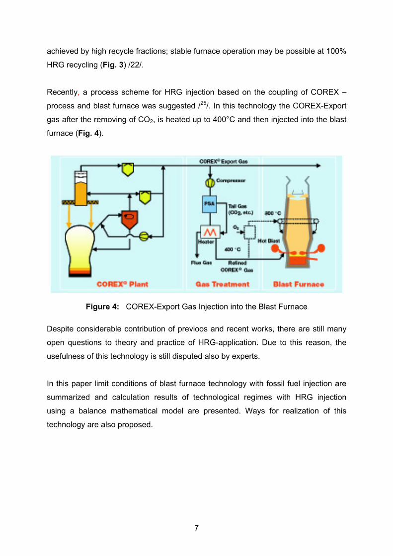
Recently, a process scheme for HRG injection based on the coupling of COREX –
process and blast furnace was suggested /25/. In this technology the COREX-Export
gas after the removing of CO2, is heated up to 400°C and then injected into the blast
furnace (Fig. 4).
Figure 4: COREX-Export Gas Injection into the Blast Furnace
Despite considerable contribution of previoos and recent works, there are still many
open questions to theory and practice of HRG-application. Due to this reason, the
usefulness of this technology is still disputed also by experts.
In this paper limit conditions of blast furnace technology with fossil fuel injection are
summarized and calculation results of technological regimes with HRG injection
using a balance mathematical model are presented. Ways for realization of this
technology are also proposed.
8
2. Effect of fossil and artificial auxiliary fuels on the blast furnace processInjecting fossil reducing agents influences strongly the heat exchange, the gas
permeability and the slag regime in the blast furnace. In numerous works both
changes of the blast furnace operating condition as well as the conversion processes
in the raceway have been investigated. From this reason only some aspects of the
change in the raceway conditions, in the gas permeability and liquid product drainage
as well as special features of HRG injecting are regarded here.
2.1. Flame temperature and oxidizing potential of the raceway
By injecting auxiliary fuels, flame temperature is reduced since the bosh gas volume
rises more strongly than the quantity of heat generated by fuel gasification and
carried by the hot blast. The amount of heat generated by combustion of auxiliary
fuels decreases in comparison to the heat amount released by the coke combustion
because of their pyrolysis and lower heat of incomplete combustion.
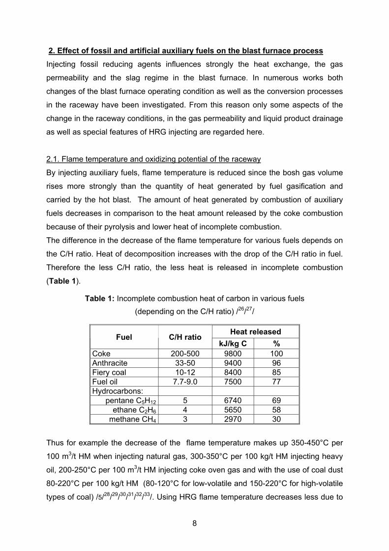
The difference in the decrease of the flame temperature for various fuels depends on
the C/H ratio. Heat of decomposition increases with the drop of the C/H ratio in fuel.
Therefore the less C/H ratio, the less heat is released in incomplete combustion
(Table 1).
Table 1: Incomplete combustion heat of carbon in various fuels(depending on the C/H ratio) /26/27/
Heat releasedFuel C/H ratiokJ/kg C %
Coke 200-500 9800 100Anthracite 33-50 9400 96Fiery coal 10-12 8400 85Fuel oil 7.7-9.0 7500 77Hydrocarbons:
pentane C5H12 5 6740 69ethane C2H6 4 5650 58
methane CH4 3 2970 30
Thus for example the decrease of the flame temperature makes up 350-450°C per
100 m3/t HM when injecting natural gas, 300-350°C per 100 kg/t HM injecting heavy
oil, 200-250°C per 100 m3/t HM injecting coke oven gas and with the use of coal dust
80-220°C per 100 kg/t HM (80-120°C for low-volatile and 150-220°C for high-volatile
types of coal) /5/28/29/30/31/32/33/. Using HRG flame temperature decreases less due to
9
the insignificant pyrolysis as well as high temperature. Beyond that the problem of
incomplete combustion does not apply. Compared to fossil fuels thereby a far higher
quantity of HRG is applicable.
To keep the flame temperature at a constant level is usual technological mode of
blast furnace operation with combined blast. When injecting auxiliary fuels the
decrease of flame temperature is adapted by enriching blast with process oxygen,
incresase in blast temperature or decrease in humidity of the blast. Nevertheless the
constant value of the flame temperature may not maintain the required temperature
and composition of hot metal in changing technological conditions /34/. Following
equation for flame temperature, needed to save initial temperature and composition
of hot metal under changed technological conditions, was set up on the base of the
heat balance in the lower blast furnace zone viewing two technological regimes
conditions - with (index 1) and without injecting reducing agents (index 0) /35/:
T1 = Tn + [ 1 - A (rd o - rd 1 ) / rd o ] (K0 V0 / K1V1) (T0 - Tn) (1) where: T: flame temperature, °C Tn : temperature of burden and gases in the reserve zone of heat exchange (idle
zone), °C rd : direct reduction rate, (-) K : coke rate, kg/t HM V: bosh gas volume, m3/t coke A = 1 – 0.9 / Wb Wb : water equivalent of burden, kJ/t HM.
The necessary flame temperature as it follows from Eq. (1) depends on furnace
operation conditions. E.g. a change in direct reduction rate, gas volume or coke rate
requires correction in the flame temperature value. The PCI affects the necessary
flame temperature not only because the drop in direct reduction rate but also due to
the radiation of the coal particles within the raceway /34/36/.
The oxidizing potential of the raceway at constant oxygen concentration in blast
depends on the rate of injected fuels and can be maintained or changed controlling
their ratio, according to the equation /37/:

10
∆ S2 = - (m/n) ∆ S1 , (2)
where: S1 and S2: injecting rate of gaseous and liquid / solid respectively, m3/kgHM
(kg/kgHM)
m, n: theoretical oxygen consumption for combustion of 1 m3 gaseous fuel
and 1 kg liquid / solid fuel respectively, m3;
The coefficients m and n are calculated by the equations /37/38/:
m = 2 (H2) + 2 (CO) + 2 (CH4) + 3.5(C2H6) + 5(C3H8) +...
n = 1.8667 Cw + 11.2 Hw,
where H2, CO, CH4, C2H6, C3H8...: hydrogen, carbon monoxide, methane,
methane, propane and other components in gaseous fuel, %/100;
Cw Hw : content of carbon and hydrogen in liquid / solid fuel, %/100.
To keep oxidizing potential e.g. for the case of simultaneous PC and NG injection, a
PC consumption change by 10 kg should be accompanied according to eq. (2) by
change in NG consumption in the opposite direction by 7-8 m3.
Injection of HRG does not require additional oxidizing potential of the raceway.
2.2. Gas permeability and drainage of liquid products
The lower the coke rate, the more difficult to maintain the gas permeability in the
cohesive zone and in lower part of the furnace as well as the drainage of the melted
products. The minimum coke rate which maintains the drainage of the liquid
products in a counter flow corresponds to the critical voidage of 0,23-0,24 m3/m3 /39/.
High coke qualitiy is necessary to limit the contamination of the furnace especially in
the area of the dead man as well as to guarantee the necessary hydraulic and gas
dynamic conditions in the hearth.
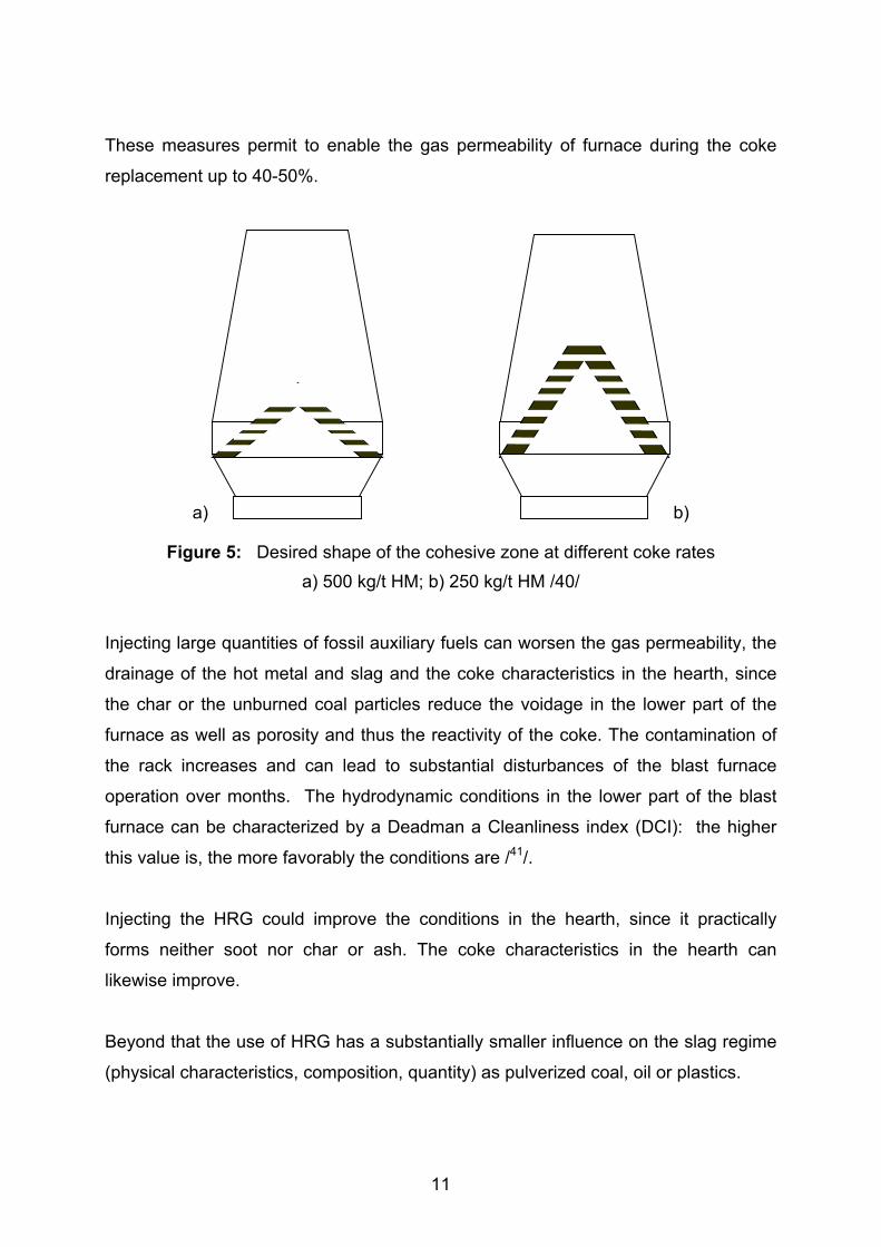
The following measures are necessary for the preservation of the gas permeability at
the substantial decrease of coke rate /40/:
- the reverse V-profile of the cohesive zone
- the peak of the cohesive zone should be shifted possibly far upwards to
maintain a sufficient number of coke windows and therefore the sufficient gas
permeability in the cohesive zone (Figure 5)
- during a retention of the coke layer thickness the ore layer thickness must be
decreased.
11
These measures permit to enable the gas permeability of furnace during the coke
replacement up to 40-50%.
a) b)
Figure 5: Desired shape of the cohesive zone at different coke ratesa) 500 kg/t HM; b) 250 kg/t HM /40/
Injecting large quantities of fossil auxiliary fuels can worsen the gas permeability, the
drainage of the hot metal and slag and the coke characteristics in the hearth, since
the char or the unburned coal particles reduce the voidage in the lower part of the
furnace as well as porosity and thus the reactivity of the coke. The contamination of
the rack increases and can lead to substantial disturbances of the blast furnace
operation over months. The hydrodynamic conditions in the lower part of the blast
furnace can be characterized by a Deadman a Cleanliness index (DCI): the higher
this value is, the more favorably the conditions are /41/.
Injecting the HRG could improve the conditions in the hearth, since it practically
forms neither soot nor char or ash. The coke characteristics in the hearth can
likewise improve.
Beyond that the use of HRG has a substantially smaller influence on the slag regime
(physical characteristics, composition, quantity) as pulverized coal, oil or plastics.

12
2.3. Limit for fossil auxiliary fuels and fundamental advantages of HRG
The highest rate of NG injection of 155 kg/tHM was achieved in USA (coke rate was
310 kg/tHM), in Russia and Ukraine its rate at some BFs was 150-170 m3/tHM /5/42/.
The higher NG rate leads to local supercooling of the hearth, an increment of slag
viscosity, incompleteness of NG combustion with char generation, and worsening of
melting products drainage.
The injection rate of coke oven gas (COG) (which is only injected occasionally in
some blast furnaces because its free resources at an integrated plant are usually
limited) is changed from 100 to 250-300 m3/tHM /5/11/42/; the coke/COG replacement
ratio makes up 0.4-0.45 kg/m3 compare to 0.8-0.85 kg/m3 for NG.
PC is the most common auxiliary fuel. Its injection rate of 200-230 kg/tHM with the
drop in coke consumption down to 280-300 kg/tHM has been achieved during trial
periods at some BFs /11/12/43/. Theoretical, laboratory and pilot investigations as well
as the latest industrial experience show that PC rate can be raised up to at least 250
kg/tHM and BF operating with coke/coal ratio = 50/50 (%) could be maintained /5,37/.
On the other hand, average PC rate in Europe rarely exceeds 130-150 kg/tHM (in
1999 only IJmuiden 6, the Netherlands operated with PC rate of 204 kg/tHM and
coke rate of 316 kg/tHM /44/) mainly because of the problems with complete
combustion within the raceway, gas permeability in the shaft, dirtying of the deadman
and as a result irregular furnace operation and decrease in productivity. Increase in
PC rate up to the record level of 266 kg/tHM even under perfect burden and
operational conditions at Fukuyama No.3 BF (NKK, Japan) did not result in record
low coke rates /45/.
Total consumption of injected fuel at co-injection of NG, PC and /or oil does also not
exceed 180-230 kg/tHM /5/.
Considerable success in finding solutions to the above mentioned problems as
- the provision of the complete or at least high rate of auxiliary fuel utilization,
13
- the provision of a suitable permeability under conditions of a very large decrease
of the coke layer thickness and of the thickness of the coke windows in the
cohesive zone,
- the compensation for the negative changes of heat fluctuation and slag formation
processes,
- the maintenance of a uniform distribution of injected fuels around the furnace
circumference
has been recently made. Further investigations and improvements of blast furnace
operation with high rate of fossil fuel injection as well using of already developed
measures (optimization of burden distribution, blast oxygen enrichment, improvement
in delivery of oxidizing agent to the coal jet and their mixing, optimizing of coal
grinding, use of catalysts, use of ionized air and injection of a gas-oxygen mixture for
intensifying natural gas combustion etc. /5,35/46/ could maintain a stable furnace
operation at high PCI as well as NG or oil injection and increase the achieved
average level of injected fuel rate.
It is necessary to clearly understand that all efforts in the direction of increasing the
PC rate could shift the achieved limit of PCI to a higher level but not eliminate the
limitation on fossil fuel injection generally.
Hot reduction gases have following fundamental advantages in comparison with the
fossil auxiliary fuels:
- they enable to introduce a higher quantity of carbon monoxide and hydrogen, as
fossil fuels
- the quantity of hot reduction gas in combination with enriching blast with oxygen
could be increased up to a nitrogen-free-process, because no (or almost none)
heat is necessary for the splitting of the hydrocarbons and in the raceway no
processes of combustion do take place
- the relative share of CO and H2 increases because of reduction of the nitrogen
quantity
- the furnace productivity increases, because in the fraction of time, more carbon
converses and more raw material gets melted
- the mixing of the gas stream with the hot blast is improved. This leads to the
increase of CO - and H2- utilization rates

14
- the lower part of the blast furnace remains "cleaner" and the coke characteristics
under the cohesive zone can be maintained.
The advantages of the HRG mentioned above refer on the injection into the hearth.
When injecting into the shaft or belly, in the lower part of the blast furnace with
reduced gas permeability the gas volume would not rise, so that an increase of the
furnace productivity is possible; beyond that the physical heat of the HRG is entered
at that point, where the temperature is low.
The decisive argument agaist the HRG injection into the shaft consisits of enormous
difficulty to provide the necessary gas distribution in the shaft, especially in the
cohesive zone. The distribution of the HRG all-over the furnace radius and the gas-
penetrating up to the center will be one of the main problems of this method of HRG
injection.
Further disadvantages of the HRG injection into the shaft consisit of the costly and
complex constructional modifications; the shaft is more stressed by the additional
tuyere rank.
3. Calculations of technological regimes for the Injection of HRG into the blastfurnace
3.1 Mathematical ModelThe calculations represented in the following were carried out using a mathematical
model of the Donetsk State University of Technology /47/. This is a total balance
model that does not require any input parameters to be assumed (e.g., the “ Four
Fluid Model" /26/ needs raceway geometry, softening temperature of the burden,
distribution of burden- and coke size all-over the furnace radius, coke size in
deadman and other parameters of the inner state as input parameters).
The model calculates the coke rate, the blast volume, parameters of the inner state
(bosh gas volume, flame temperature, direct reduction rate, heat generated and
absorbed), and output parameters (slag volume, relative productivity, top gas
composition and temperature, etc.). The model was developed on the base of a
complex method of Prof. A.N.Ramm /26/. This method based on the interrelations of

15
material and heat balances equations. Its characteristic feature is following: a system
of equations of material balance of different input components according to a target
hot metal chemical composition is formed; to this system one equation of heat
balance is added which determines the correlation between coke rate and remaining
components. The coke rate is introduced as unknown value in all equations of the
material balance, rates of iron bearing and flux components in the heat balance
equation.
The main steps of calculation are:
1. O2-quantity released during reduction
2. useful heat output of physical and chemical conversions of burden, coke and coal
ash
3. total quantity of C, H, O and N in 1m³ or 1kg of each injected fuel as well as the
enthalpy and calorific value (by burning in the raceway)
4. volume of bosh gas, direct reduction rate and top gas temperature
5. coke and total fuel consumption, as well as blast volume
6. needs of fluxes, slag volume, top gas parameter (volume, composition, calorific
value)
7. heat balance
8. flame temperature
9. change in the productivity and intensity of the coke combustion.
Furnace productivity is determined with the consideration of material gas permeability
/47/:
P = P° * (vg/vg) * (d° * Θ° * γ°/ d * Θ * γ)1/2
where: d = (L * vb/vc + 1) * (vb/vc + 1) -1
p: blast furnace productivity, t / 24 h
Θ: average gas temperature, K
vg : wet top gas volume, m³ / kg HM
γ : average gas density, kg / m²
vb, vc : burden and coke volume respectively, m³ / kg HM
L : ratio of gas pressure drop in
index 0 refers to initial (base) conditions.
16
3.2 Calculation conditionsThe injection of hot reducing gases with various parameters into the blast furnace
hearth has been simulated. Calculations have been carried out for two blast furnaces
operating under the different conditions. Blast furnace 1 (BF-1) with a working volume
of about 1000 m3 and 12 tuyeres represents the typical blast furnace with only coke
operation without enriching blast with oxygen (21% O2). The hot blast temperature is
1080°C. The produced pig iron contains 0.6% Si and 0.040% S. Blast furnace 2 (BF-
2) (working volume of about 3800 m3, 40 tuyeres) represents a modern blast furnace
with PCI and O2-enrichment of the hot blast. The hot blast temperature is in the range
1160°C to 1180°C and the produced pig iron contains about 0.37% Si and 0.029% S.
The burden of BF-1 consists of 59.1% sinters, 34.3% pellets and 6.6% lump ore; the
S-content in the coke makes up 0.5%. At the BF-2 the sinter/pellets ratio in the
burden makes up 2:1. In Tables 2 and 3 the burden and coke parameters for both
blast furnaces as well as PC parameters for BF-2 are given.

17
Table 2: Burden consumption and composition
Burden BF-1 BF-2Sinter:consumption (kg/t HM) 935 923
composition (%)
Fe 56,83 58,09FeO 5,87 4,90CaO 9,86 9,67SiO2 5,80 5,09MgO 1,65 1,54Al2O3 1,40 1,05MnO 0,52 0,22
Pellets:consumption (kg/t HM) 543 437
composition (%)
Fe 65,08 65,70FeO 0,31 1,50CaO 2,94 0,92SiO2 2,77 4,70MgO 0,09 0,26Al2O3 0,65 0,30MnO 0,17 0,07
Lump Ore:consumption (kg/t HM) 104 189
composition (%)
Fe 65,05 65,50FeO 0,78 2,00CaO 0,22 0,90SiO2 2,55 8,20MgO 0,04 0,90Al2O3 1,36 0,50MnO 0,15 0,10
Limestone:consumption (kg/t HM) - 38
composition (%) -CaO - 53,5SiO2 - 1,8MgO - 0,7Al2O3 - 0,3MnO - 0,05
18
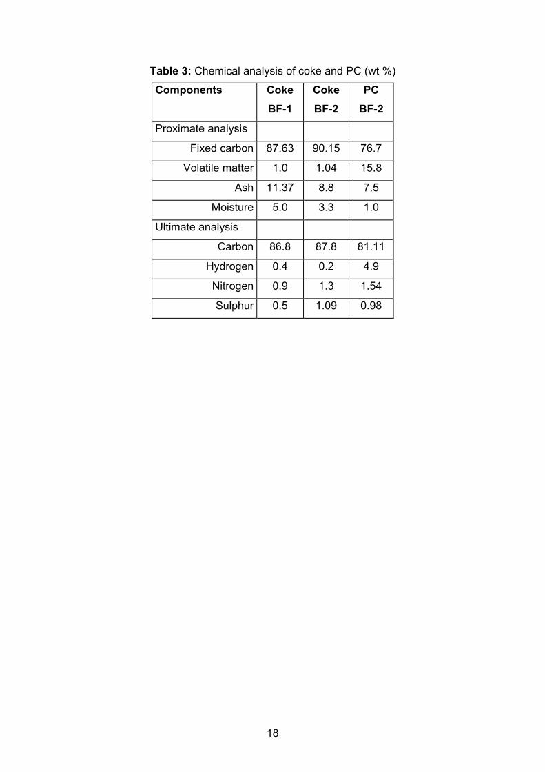
Table 3: Chemical analysis of coke and PC (wt %)
Components CokeBF-1
CokeBF-2
PCBF-2
Proximate analysis
Fixed carbon 87.63 90.15 76.7
Volatile matter 1.0 1.04 15.8
Ash 11.37 8.8 7.5
Moisture 5.0 3.3 1.0
Ultimate analysis
Carbon 86.8 87.8 81.11
Hydrogen 0.4 0.2 4.9
Nitrogen 0.9 1.3 1.54
Sulphur 0.5 1.09 0.98
19
3.3 Calculation results3.3.1 Influence of HRG-parametersThe influence of HRG temperature and composition on blast furnace process has
been investigated for the conditions of the BF-2 (hot blast temperature 1180°C and
PCI rate 160 kg/t HM). Four cases with the same injection rates of PCI and HRG
(160 kg/t HM and 150 m³/t HM respectively) were examined and compared with the
basic case. A constant flame temperature of 2150°C was maintained by controlling
the oxygen concentration in the blast.
The main results of the calculation are shown in Table 4. While the HRGs of cases 1
and 2 are produced by coal gasification, in case 3 a HRG is used, which is generated
by steam conversion of natural gas. The reducing gas used in case 4 is top gas,
where CO2 is stripped from the recycled gas.
The HRG in case 1 is characterised by a high content of oxidizing agents (CO2+H2O
= 13,5%) as well as a low temperature of 700°C. It is shown, that the physical heat of
the HRG can not compensate the lower heat entry with the hot blast (approx. by 430
kJ /kgHM in comparison to the basis case) and the heat consumption for the
decomposition of carbon dioxide and water steam (271 kJ /kgHM). For that reason
the coke rate has not been changed despite the decrease in the direct reduction rate
(rd) by 8% in comparison to the basis case. The furnace productivity increased by 11
%.
At reduction of the oxidising agents (CO2+H2O) up to 3,5% and an increase of the
blast temperature up to 1000°C (case 2) the coke consumption was lowered by 35
kg/tHM and the furnace productivity increased around by 11 %.
The use of HRG with 3 % CO2, 3 % CH4, high H2 - content and t = 1000°C (case 3)
makes possible to reduce the coke consumption by 47 kg/tHM, because of the strong
decrease in direct reduction rate (by 12 %) and less needs of heat for the
decomposition of CO2 and H2O (about 50 kJ/kg HM). The CO- and H2-conversion
degrees improve. The productivity was increased by 15%.
The recycled top gas (after CO2 removing) is characterised by a high content of CO
and H2 (72 and 25 % respectively) and low content of oxidixing agents (CO2 + H2O =

20
3 %). Injection of this gas with a temperature of 1000°C into the hearth (case 4)
makes possible a reduction of coke rate by 27 kg /t RE (8,5%) as well as an increase
in productivity by 8 %.
Table 4: Influence of parameters of HRG on blast furnace operating parametersBase 1 2 3 4
Blast:temperature, °C 1180 1180 1180 1180 1180oxygen, % 24,1 34,3 31,0 31,7 30,5PC, kg/tHM 160 160 160 160 160HRG, m3/tHM 0 150 150 150 150composition in %: H2 33,1 44,0 71,0 25,0
CH4 0,0 1,0 3,0 0,0CO 52,9 51,5 22,6 72,0N2 0,0 0,0 1,0 0,0
CO2 7,0 3,0 3,0 1,5H2O 6,5 0,5 0,0 1,5
temperature, °C 700 1000 1000 1000
direct reduction rate, % 52,9 44,7 44,0 40,8 46,3Coke, kg/tHM 345 345 310 298 318total fuel, kg/tHM 511 511 477 464 484blast vol., m3/tHM 1000 724 740 718 756Top gas, %composition in % CO2 20,8 24,0 24,0 24,2 23,8
CO 26,1 34,8 31,3 29,0 32,8H2 3,5 6,5 6,7 8,6 5,5N2 49,5 34,7 37,9 38,2 37,9
calorific power, kJ/m3 3685 5107 4685 4595 4733temperature, °C 166 107 125 126 125CO utilization rate 43,7 40,2 42,8 44,8 41,5H2 utilization rate 46,1 42,3 45,1 47,3 43,8Heat balance, kJ/kgHMcombust. of C of coke 1420,0 1584,1 1301,0 1255,3 1319,3combust. of PC 1092,1 1092,1 1092,1 1092,1 1092,1combust. of HRG 0,0 -271,2 -64,1 -49,7 -57,2heat carried by PC 11,5 11,5 11,5 11,5 11,5heat carried by HRG 0,0 149,6 217,0 222,1 213,3heat carried by the blast 1554,3 1124,2 1149,3 1114,4 1174,8oxidizing C -- CO 1096,3 934,4 920,1 855,6 964,9oxidizing CO -- CO2 3969,9 4106,8 4035,8 3877,2 4120,0oxidizing H2 --H2O 500,9 717,0 807,1 1075,2 643,0total in reduction area 5567,0 5758,2 5763,0 5808,0 5727,9total heat generated 9645,0 9448,5 9469,9 9453,8 9481,9useful heat absorbed 8868,8 8868,9 8852,5 8846,5 8856,0heat in top gases 370,4 214,3 249,7 244,9 253,6external heat losses 407,8 369,0 370,7 364,6 375,4total heat absorbed 9647,0 9452,3 9472,9 9456,0 9485,0
flame temperature, °C 2150 2150 2150 2150 2150Productivity, % 100,0 111,3 110,9 114,8 108,4
21
3.3.2. Only HRG injection and co-Injection of HRG and PCIn Table 5 the calculation results for the BF-2 operating conditions are shown at
simultaneous injection of PC and HRG. The parameters of HRG are equal for all
cases:
composition: H2 = 33 %, CO = 60 %, CH4 = 3 %, CO2 = 4 %
temperature: 1000°C.
The cases 1 and 2 represent the partly and total substitution of pulverized coal by
HRG. These technological regimes are of no interest for practice, since the modern
blast furnace technology and equipment for PC preparation and guarantee an
effective use of 150-180 kg /tHM PC, thus the advantages of HRG can not be
realized. As consequence the coke rate rises.
Case 3 shows the co-injection of HRG and “standard level” of PC (150 kg /tHM coal +
150 m3 /tHM HRG). The direct reduction rate decreases by more than 8% in
comparison with the basis case because of the high content of reducing agents. This
is the primary cause for the coke saving of approx. 35 kg /tHM despite the drop in
heat supply. This technological regime is accompanied by lowering of the blast
volume by 25 %, the bosh gas volume by 12 % and the top gas temperature by
approx. 40°C. The hydrogen content in the top gas rises in comparison with the basis
case from 3.4 to 6.1%; the nitrogen content decreases from 49.6 to 37.6 % because
of the increased quantity of reducing agents and oxygen content in the blast. The
calorific value of the top gas rises by 28%. Other operating parameters (slag volume,
flux consumption etc.) don’t change. The furnace productivity increases by 10 %.
In cases 4-6 the increase in PCI by 50-100 kg/tHM and in the furnace productivity by
15-30% were possible due to a rise in the oxygen concentration in the blast. Thereby
an essential coke saving of 83-150 kg/tHM was reached. The efficiency of heat use
rises from 91,9 in the basis case to 94,2-96,0%. When injecting 250 kg /tHM PC and
300 m3/tHM HRG (case 6), blast volume and O2-enrichment of the blast make up 315
m³/tHM and 75% respectively. The top gas has low temperature, contains 60%
CO+H2 and only 8% N2. Its calorific value makes up approx. 7350 kJ /m³. The high
thermal and reducing potential of this gas can be utilized in the blast furnace and/or
other aggregates.
22
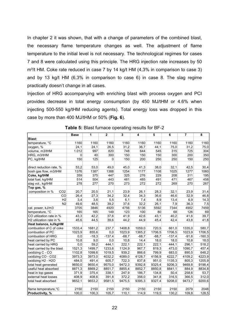
In chapter 2 it was shown, that with a change of parameters of the combined blast,
the necessary flame temperature changes as well. The adjustment of flame
temperature to the initial level is not necessary. The technological regimes for cases
7 and 8 were calculated using this principle. The HRG injection rate increases by 50
m³/t HM. Coke rate reduced in case 7 by 14 kg/t HM (4,3% in comparison to case 3)
and by 13 kg/t HM (6,3% in comparison to case 6) in case 8. The slag regime
practically doesn’t change in all cases.
Injection of HRG accompanying with enriching blast with process oxygen and PCI
provides decrease in total energy consumption (by 450 MJ/tHM or 4.6% when
injecting 500-550 kg/tHM reducing agents). Total energy loss was dropped in this
case by more than 400 MJ/tHM or 50% (Fig. 6).
Table 5: Blast furnace operating results for BF-2Base 1 2 3 4 5 6 7 8
Blast:temperature, °C 1160 1160 1160 1160 1160 1160 1160 1160 1160oxygen, % 24,1 24,1 26,5 31,2 36,7 44,1 75,0 31,2 75,0volume, m3/tHM 1.012 997 820 748 644 545 315 725 304HRG, m3/tHM 0 40 300 150 150 150 300 200 350PC, kg/tHM 150 125 0 150 200 250 250 150 250
direct reduction rate, % 53,2 53,0 49,0 45,0 41,3 38,0 32,1 42,5 30,4bosh gas flow, m3/tHM 1376 1387 1388 1254 1177 1108 1025 1277 1060Coke, kg/tHM 359 375 447 325 276 229 208 311 195total fuel, kg/tHM 514 504 443 481 485 491 471 467 458slag vol., kg/tHM 278 277 270 273 272 272 269 270 267Top gas, %composition in % CO2 20,7 20,5 21,1 23,9 26,1 28,3 32,1 23,9 31,4
CO 26,4 27,3 34,2 32,4 34,3 36,6 46,6 32,9 46,8H2 3,4 3,6 5,5 6,1 7,4 8,9 13,4 6,9 14,3N2 49,6 48,5 39,2 37,6 32,2 26,1 7,9 36,3 7,5
cal. power, kJ/m3 3705 3846 4920 4756 5136 5592 7344 4902 7459temperature, °C 165 165 149 123 100 80 68 126 69CO utilization rate in % 43,3 42,2 37,6 41,9 42,6 43,1 40,2 41,6 39,7H2 utilization rate in % 45,6 44,5 39,6 44,2 44,9 45,4 42,4 43,8 41,8Heat balance, kJ/kgHMcombustion of C of coke 1533,4 1681,2 237,7 1408,8 1059,0 720,5 661,0 1335,0 580,7combustion of PC 1023,9 855,6 0,0 1023,9 1365,2 1706,5 1706,5 1023,9 1706,5combustion of HRG 0,0 -18,3 -137,4 -68,7 -68,7 -68,7 -137,4 -91,6 -160,3heat carried by PC 10,8 9,0 0,0 10,8 14,4 18,0 18,0 10,8 18,0heat carried by HRG 0,0 59,2 444,1 222,1 222,1 222,1 444,1 296,1 518,2heat carried by the blast 1521,3 1499,7 1233,6 1124,9 967,7 819,3 473,0 1090,7 457,4oxidizing C - CO 1102,8 1099,6 1019,5 939,2 866,6 799,9 683,0 890,5 648,2oxidizing CO - CO2 3973,3 3973,0 4032,2 4089,0 4128,7 4156,9 4222,7 4109,2 4223,9oxidizing H2 - H2O 484,5 491,4 605,7 722,3 837,8 951,0 1135,3 805,3 1205,9total heat generated 9650,0 9650,4 9575,0 9472,3 9392,8 9325,4 9206,3 9469,8 9198,4useful heat absorbed 8871,3 8869,2 8851,7 8855,4 8852,7 8850,8 8841,1 884,9 8834,8heat in top gases 371,9 375,4 338,1 247,9 186,7 134,8 50,4 258,6 53,7external heat losses 408,9 408,6 391,8 372,2 356,0 341,8 316,5 366,5 312,0total heat absorbed 9652,1 9653,2 9581,5 9475,5 9395,3 9327,4 9208,0 9473,7 9200,6
flame temperature,°C 2150 2150 2150 2150 2150 2150 2150 2079 2048Productivity, % 100,0 100,3 105,7 110,1 114,9 119,5 130,2 109,8 128,5
23
a) Total Energy Consumption
8.8009.0009.2009.4009.6009.800
1 2 3 4 5 6 7Cases
MJ
/ t H
M
d) External Energy Loss
250275300325350375400425450
0,00 20,00 40,00 60,00 80,00Oxygen content in Blast (%)
MJ
/ t H
Mb) Total Energy Loss
0
100
200
300
400
1 2 3 4 5 6 7Cases
MJ
/ t H
M
e) Total Energy Consumption
9.1009.2009.3009.4009.5009.6009.700
0 100 200 300 400 500 600PC+HRG, kg / t HM
MJ
/ t H
M
c) External Energy Loss
050
100150200250300350400450
1 2 3 4 5 6 7Cases
MJ
/ t H
M
f) Total Energy Loss
0
200
400
600
800
1.000
100 200 300 400 500 600PC+HRG, kg / t HM
MJ
/ t H
M
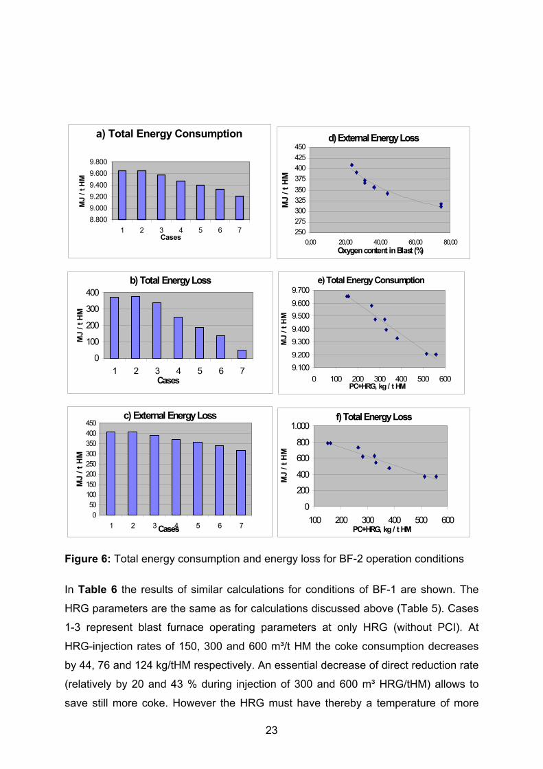
Figure 6: Total energy consumption and energy loss for BF-2 operation conditions
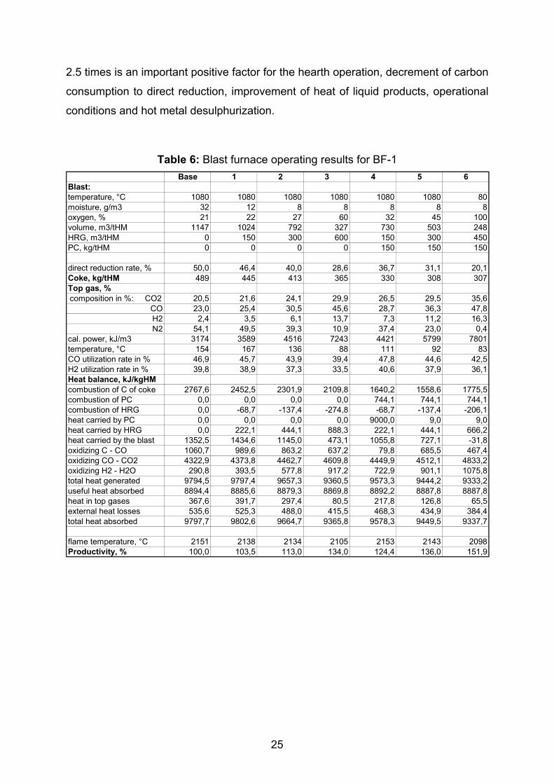
In Table 6 the results of similar calculations for conditions of BF-1 are shown. The
HRG parameters are the same as for calculations discussed above (Table 5). Cases
1-3 represent blast furnace operating parameters at only HRG (without PCI). At
HRG-injection rates of 150, 300 and 600 m³/t HM the coke consumption decreases
by 44, 76 and 124 kg/tHM respectively. An essential decrease of direct reduction rate
(relatively by 20 and 43 % during injection of 300 and 600 m³ HRG/tHM) allows to
save still more coke. However the HRG must have thereby a temperature of more
24
than 1000°C. Injection of 150 m³ HRG/tHM doesn’t require perceptible changes in
the combined blast parameters. At 300 m³ HRG/t HM the blast moisture was reduced
down to the atmospheric value and a blast volume to less than 800 m³/tHM; the
oxygen enrichment rises up to 27%. At 600 m³ HRG/tHM the blast volume decreases
to approx. 330 m³/t HM and the O2-enrichment makes up 60 %. The furnace
productivity rises in cases 1-3 by 3.5, 13 and 34% respectively.
Cases 4-5 illustrate the operating parameters at co-injection of PC (150 kg/t HM) and
HRG (150 and 300 m³/t HM). Besides a considerable coke saving of 160 (32%) and
180 kg/t HM (37%) these technological regimes provide an increase in furnace
productivity of 24 and 36% respectively. The effectiveness of heat use increases in
case 5 by 3.3%; the heat loss decreases from 5.5% in the basis case to 4.5%.
Case 6 represents a special technological regime, the so-called „Oxy-Coal-Process“.
Since in this process 100 % O2 is injected i.e. no hot blast is used, neither cowpers
are necessary nor other costs for the heating of blast arise. This regime enables coke
saving of 182 kg/t HM and increase in furnace productivity by 52 %. Extra economic
benefits could be derived by utilization of the top gas with a high calorific value which
contains no nitrogen.
Total energy consumption decreases by 55-80 MJ/tHM for every 100 m3/tHM of
HRG. The higher value corresponds to the cases with PC co-injection (Fig. 7, e).
Change in the value of energy loss is similar. E.g., external energy losses make up
20 and 28 MJ/tHM per 100 m3/tHM of HRG for the cases without and with co-
injection of PC respectively (Fig. 7, f).
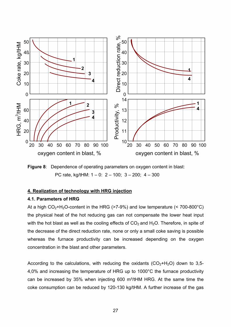
Further study of blast furnace operation with the injection of preheated top gas after
CO2 removal (HRG parameters are the same as in Table 4, case 4) has been carried
out under BF-2 conditions for the wide range of oxygen enrichment of blast and PCI
rate. Hot metal temperature has been kept on a constant level by maintaining the
necessary value of flame temperature. Results are presented in Fig 8.
Maximum coke saving of about 370 kg/tHM or more than 70% has been achieved
when injecting over 400 m3/tHM HRG, 300 kg/tHM PC with blast consisting almost
completely of cold process oxygen (80-90%O2). Decrease in direct reduction rate by
25
2.5 times is an important positive factor for the hearth operation, decrement of carbon
consumption to direct reduction, improvement of heat of liquid products, operational
conditions and hot metal desulphurization.
Table 6: Blast furnace operating results for BF-1Base 1 2 3 4 5 6
Blast:temperature, °C 1080 1080 1080 1080 1080 1080 80moisture, g/m3 32 12 8 8 8 8 8oxygen, % 21 22 27 60 32 45 100volume, m3/tHM 1147 1024 792 327 730 503 248HRG, m3/tHM 0 150 300 600 150 300 450PC, kg/tHM 0 0 0 0 150 150 150
direct reduction rate, % 50,0 46,4 40,0 28,6 36,7 31,1 20,1Coke, kg/tHM 489 445 413 365 330 308 307Top gas, %composition in %: CO2 20,5 21,6 24,1 29,9 26,5 29,5 35,6
CO 23,0 25,4 30,5 45,6 28,7 36,3 47,8H2 2,4 3,5 6,1 13,7 7,3 11,2 16,3N2 54,1 49,5 39,3 10,9 37,4 23,0 0,4
cal. power, kJ/m3 3174 3589 4516 7243 4421 5799 7801temperature, °C 154 167 136 88 111 92 83CO utilization rate in % 46,9 45,7 43,9 39,4 47,8 44,6 42,5H2 utilization rate in % 39,8 38,9 37,3 33,5 40,6 37,9 36,1Heat balance, kJ/kgHMcombustion of C of coke 2767,6 2452,5 2301,9 2109,8 1640,2 1558,6 1775,5combustion of PC 0,0 0,0 0,0 0,0 744,1 744,1 744,1combustion of HRG 0,0 -68,7 -137,4 -274,8 -68,7 -137,4 -206,1heat carried by PC 0,0 0,0 0,0 0,0 9000,0 9,0 9,0heat carried by HRG 0,0 222,1 444,1 888,3 222,1 444,1 666,2heat carried by the blast 1352,5 1434,6 1145,0 473,1 1055,8 727,1 -31,8oxidizing C - CO 1060,7 989,6 863,2 637,2 79,8 685,5 467,4oxidizing CO - CO2 4322,9 4373,8 4462,7 4609,8 4449,9 4512,1 4833,2oxidizing H2 - H2O 290,8 393,5 577,8 917,2 722,9 901,1 1075,8total heat generated 9794,5 9797,4 9657,3 9360,5 9573,3 9444,2 9333,2useful heat absorbed 8894,4 8885,6 8879,3 8869,8 8892,2 8887,8 8887,8heat in top gases 367,6 391,7 297,4 80,5 217,8 126,8 65,5external heat losses 535,6 525,3 488,0 415,5 468,3 434,9 384,4total heat absorbed 9797,7 9802,6 9664,7 9365,8 9578,3 9449,5 9337,7
flame temperature, °C 2151 2138 2134 2105 2153 2143 2098Productivity, % 100,0 103,5 113,0 134,0 124,4 136,0 151,9

26
a) Total Energy Consumption
910092009300940095009600970098009900
Base 1 2 3 4 5 6Cases
MJ
/ t H
M
HRG-InjectionPC+HRG-
d) External Energy Loss
350
400
450
500
550
20 40 60 80 100Oxygen Content in Blast, %
MJ/
t HM
b) Total Energy Loss
0100200300400500600700800900
1000
Base 1 2 3 4 5 6Cases
MJ/
t HM
HRG-InjectionPC+HRG-
e) External Energy Loss
300
350
400
450
500
550
600
0 100 200 300 400 500 600HRG (m³/ t HM)
MJ/
t HM
PC = 0
PC = 150
c) External Energy Loss
0
100
200
300
400
500
600
Base 1 2 3 4 5 6Cases
MJ
/ t H
M
HRG-InjectionPC+HRG-Injection
f) Total Energy Loss
9100
9200
9300
9400
9500
9600
9700
9800
9900
0 100 200 300 400 500 600HRG in m³/t HM
MJ
/ t H
M
PC = 0
PC = 150
Figure 7: Total energy consumption and energy loss for BF-1 operation conditions
27
Figure 8: Dependence of operating parameters on oxygen content in blast:
PC rate, kg/tHM: 1 – 0: 2 – 100; 3 – 200; 4 – 300
4. Realization of technology with HRG injection4.1. Parameters of HRGAt a high CO2+H2O-content in the HRG (>7-9%) and low temperature (< 700-800°C)
the physical heat of the hot reducing gas can not compensate the lower heat input
with the hot blast as well as the cooling effects of CO2 and H2O. Therefore, in spite of
the decrease of the direct reduction rate, none or only a small coke saving is possible
whereas the furnace productivity can be increased depending on the oxygen
concentration in the blast and other parameters.
According to the calculations, with reducing the oxidants (CO2+H2O) down to 3,5-
4,0% and increasing the temperature of HRG up to 1000°C the furnace productivity
can be increased by 35% when injecting 600 m³/tHM HRG. At the same time the
coke consumption can be reduced by 120-130 kg/tHM. A further increase of the gas
0
10
20
4ß
30
50
20 30 40 10050 90807060
20
40
60
0
1
23
4
1 234
0
10
20
40
30
50
20 30 40 10050 90807060
11
12
13
10
1
4
14
14
oxygen content in blast, % oxygen content in blast, %
HR
G, m
3 /tHM
Cok
e ra
te, k
g/tH
M
Dire
ct re
duct
ion
rate
, %Pr
oduc
tivity
, %
28
temperature by 100°C leads to an additional coke saving of approx. 2,5 kg per 100
m³/t HM HRG.
Injection of HRG with high hydrogen content and a few percents of methane ensures
the best operating results from the coke saving and productivity points of view. Such
a gas can be generated e.g. by steam-conversion of natural gas or coke-oven gas.
Effective use of HRG when injecting into the blast furnace hearth can be reached
under following conditions:
• gas temperature should be on the level of the hot blast temperature, e.g. 1000-
1250°C; this requirement is important when injecting high amounts of HRG
• a minimum content of oxidizing agents in the HRG (usually less than 3-5% CO2 +
H2O). Every one percent extra can cause an increase in coke consumption up to
3 %
• a constant gas composition. Variations of the chemical analysis (particularly CO
and CO2) can disturb the process and lead to an excessive consumption of coke
• economic manufacture of the HRG
4.2. Production of HRGAt present time gasification of low coal grades and top gas regeneration are the most
economic methods for HRG manufacturing.
For coal gasification effective methods should be chosen. 4 - 5 m³ HRG from 1 kg
coal can be generated by air- or steam-air-conversion of coal. Nitrogen in the
reducing gas decreases the coke / HRG replacement ratio. However this can be
compensated by increased gas temperature. The use of mini reactor / gasifiers
incorporated into the tuyere apparatus allows HRG injection with temperature of
1800-2000°C. /18/
Various technologies for coal gasification in the fluidized bed, melting reactor and
underground gasification were developed and investigated at the Institute of Ferrous
Metallurgy of the Aachen University of Technology /48/49/50/51/.
Cleaning of top gas from CO2 is usually accomplished by adding special chemical
reagents (e.g., monoethanolamine); this technology is very complicated. The removal
of carbon dioxide can also be done in gas scrubbers by solving the top gas in water

29
at high pressure. This technology is used for example in the production of synthetic
ammonia. The cowpers can be used for heating up the HRG up to 1000-1300°C.
A technology with recycled top gas after its cleaning from CO2 could also lead to
additional cost saving. Carbon dioxide can be produced in gaseous or solid phase
and utilized in the production of food, chemicals, in agriculture1, metallurgy, etc.
The recirculation of top gas in the blast furnace without removal of the oxidizers can
be used only in relatively low quantities, e.g. to compensate high temperature in the
raceway and low gas volume when enriching blast with oxygen.
4.3. Blast Furnace TechnologyThree technological variants with HRG injection were investigated:
a) the substitute of the pulverized coal (partly and completely) by HRG
b) the injection of HRG in addition to the reached level of PCI; the PC rate was kept
on the constant level
c) the injection of HRG with simultaneous increase of the PCI due to the increased
oxidation potential in the raceway.
Variant a) is of no interest for the practice because the existing equipment and
technology maintains injection of 150-180 kg/tHM PC and the advantages of HRG
can not be realized. The consequence is a rise of coke consumption. Variant b)
ensures a coke saving of approx. 20-25 kg/tHM per each 100 m³ HRG/t HM. Variant
c) provides the highest efficiency. Maintaining the flame temperature at a necessary
value, which keeps hot metal temperature and silica content, allows extra coke
saving.
Total fuel rate at HRG injection decreases almost proportional to the drop in the coke
rate: the difference corresponds to the heat generation by gasification of CH4 and
heat absorption by decomposition of CO2 and H2O.
A technology with the use of 100% of cold process oxygen requires no hot stoves
and causes no costs for the blast heating; it provides a high coke saving and an
increase in productivity. In the investigated case these values amounted 182 kg /tHM
1 Increase in CO2 in air by 2% provides an acceleration in plants growth as twice. This fact could be used for theincrease of harvest in hot houses or under glasses.
30
and 52 % respectively. Additional benefit can be achieved by the use of the top gas
as fuel or reductants, since it contains no nitrogen and has a high calorific value.
Nevertheless the optimal value of oxygen concentration in the blast should be
determined because the disadvantage of the “oxy-coal process” is the absence of
physical heat in the blast.
4.4. Tuyere apparatus designDesign of tuyere assembly for high amount of HRG, process oxygen and PC injection
in the hearth should provide a complete mixture of PC with oxidizing agent, optimal
kinetic energy of streams and reliability and simplicity in exploitation.
Conventional tuyere constructions with lances for auxiliary fuels inserted into the
inner cavity of tuyere apparatus through the blowpipe or tuyere body as well as also
tuyeres with co-axial, double lances or separate lances for fuel and local oxygen
delivery /52/53 cannot simultaneously fulfil two contradictory conditions: from the one
hand, prevent ignition of super high amount of coal in high oxygen volume in the
tuyere cavity and, from other hand, avoid the dilution of oxidizer with HRG before
burning out of coal particles.
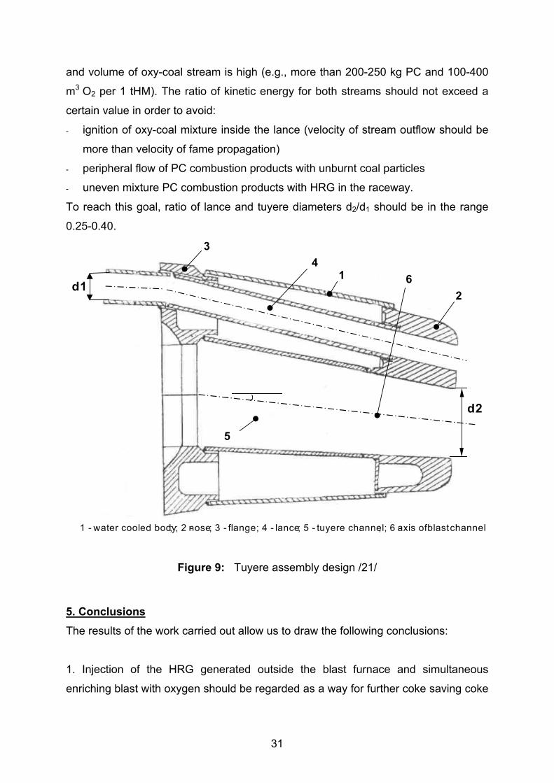
Following method and construction of tuyere apparatus can be suggested (Figure 9).
PC with process oxygen and HRG with hot blast and/or additives (e.g., water steam,
coke oven gas) are introduced into the hearth separately to improve combustion
conditions of coal and to provide more rational use of oxygen. HRG and hot blast or
HRG only in the case of “oxy-coal process” are introduced through the tuyere
channel 5. Process oxygen and PC are entered through the lance 4 which is inserted
in the water-cooled tuyere body 1. Oxy-coal mixture is formed in the lance cavity and
delivered directly into the hearth. PC burnt with oxygen at the front of the tuyere
nose in a local volume with very high temperature-oxidizing potential (gas
temperature can achieve 3000°C or more /54/). Coal gasification is accelerated
sharply and complete combustion of super high PCI is maintained. HRG and
combustion products of coal are mixed and form bosh gas with a very low content of
nitrogen. Temperature of the mixture makes up 2100-2300°C.
Flow rate through the tuyere channel is significant lower than using conventional
blast furnace technology (e.g., 500-1000 m3/tHM HRG only or HRG with hot blast)
31
and volume of oxy-coal stream is high (e.g., more than 200-250 kg PC and 100-400
m3 O2 per 1 tHM). The ratio of kinetic energy for both streams should not exceed a
certain value in order to avoid:
- ignition of oxy-coal mixture inside the lance (velocity of stream outflow should be
more than velocity of fame propagation)
- peripheral flow of PC combustion products with unburnt coal particles
- uneven mixture PC combustion products with HRG in the raceway.
To reach this goal, ratio of lance and tuyere diameters d2/d1 should be in the range
0.25-0.40.
1 - water cooled body; ; 2 -nose; 3 - flange; 4 - lance; 5 - tuyere channel; ; 6 -axis ofblastchannel
62
1
34
5
d1
d2
Figure 9: Tuyere assembly design /21/
5. ConclusionsThe results of the work carried out allow us to draw the following conclusions:
1. Injection of the HRG generated outside the blast furnace and simultaneous
enriching blast with oxygen should be regarded as a way for further coke saving coke
32
and increase in the furnace productivity beyond the injection of fossil auxiliary fuels.
Furthermore this technology promotes also decrease of the hearth contamination.
2. The HRG should be heated to about 1000°C and should have a minimal content of
CO2 and H2O (< 3-5%) as well as only minimal variations in the chemical analysis.
3. HRG can be manufactured by air- or steam-air - conversion of coal or by top gas
recycling. Low grade coals with a high ash content can be used for gasification,
whereas rich coals with low ash content should be used for PCI.
4. Co-injection of PC and HRG with simultaneous enriching blast with process
oxygen is the most effective technology. The use of HRG, pulverized coal with low
ash-content and O2-enrichment of the blast up to 80-100% can ensure an increase of
the PCI rate up to 300-400 kg/tHM and productivity of 140-150%. This technological
regime provides decrease in total energy consumption of 55-80 MJ /t HM for every
100 m³/t HM of HRG.
5. Method and tuyere apparatus design for high amount of HRG, process oxygen and
PC injection have been suggested.
Acknowledgement
The authors would like to thank Prof. S.Yaroshevskii of the Donetsk State Univ. of
Techn., Ukraine for valuable assistance,
33
References 1 H.Engeln; GEO, No.7, 2001, pp.108-1382 Stahl und Eisen 119 (1999), No.8, pp. 49-573 Iron and Steel Review (1999), Heft International ’98, p. 594 J.Pethke: Stahl und Eisen 111 (1998),No. 4. Pp. 107-112.5 H.W.Gudenau, K.Mavrommatis, A.Babich: Ironmaking (text book), Aachen (2001) http://www.iehk.rwth-aachen.de/DL-ironmaking/text_book6 H.M.Aichinger, K.Muelheims, H.B.Luengen, U.Schierloh, K.P.Stricker: Stahl und Eisen 121 (2001),No.5, p. 59-657 Ironmaking & Steelmaking, July (1999), pp.2-9.8 R.Munnix. Factors governing blast furnace productivity and coke rate, European Blast FurnaceCommittee, Lulea, October 6-8, 1999, 14 p.9 Jahrbuch Stahl 2001, Verlag Stahl und Eisen, Band 1, Duessldorf, 2000.10 A.Poos; N.Ponghis: Stahl und Eisen 111 (1991), No.8,pp. 69-7511 A.Cheng: Proc. 4th European Coke and Ironmaking Congress, Paris, June 19-22, 2000, pp.44-52.12 Gao Kezhong, Li Zhaoyi, Xu Wanren: : Proc. 4th European Coke and Ironmaking Congress, Paris,June 19-22, 2000, pp.192-195.13 W.E.Buss, H.Toll, R.Worberg: Steel Technology, (2000), No. 1, pp. 47-52.14 V.G.Voskoboinikov, B.L.Schurakovskii, A.G.Michalevich: Stal (1971), No.4, pp.290-29315 A.N.Ramm, Y.B.Karpilovskii: Stal (1971), No.4, pp.295-30316 E.N.Tikhomirov: Reducing Gases and Oxygen in the Blast Furnace, Metallurgija, Moscow, 1982,1982, 104p17 I.G.Tovarovskii, Yu.S.Yusfin, A.P.Pukhov, E.V.Prikhod’ko, A.A.Tretyak: Stal (1992), No.12, pp.11-1918 I.G.Tovarovskii, A.P.Pukhov, V.S.Shvedov et.al.: Stal (1997), No.7, pp.1-419 M.A.Tseitlin, S.E.Lasutkin, G.M.Styopin; ISIJ Int. 34 (1994), No.7, pp. 570-57320 Y.Ohno, M.Matsuura, H.Mitsufuji, T.Furukawa: ISIJ Int. 32 (1992), No.7, pp.838-84721 A.N.Ryzhenkov, V.A.Nozdrachev, S.L.Yaroshevskii, A.I.Babich, A.I.Krasavsev: Chugun (Pig Iron)(1996), No.7, pp. 7-17.22 P.R.Austin; H.Nogami; J.Yagi; ISIJ Int. 38 (1998), No.3, pp. 239-24523 H. W. Gudenau, A.Babich, S.Geimer. Proc. Sustainable Development Simulation - Investigation –Measurement Workshop Brazil, April 2001, pp. IV.1-6.24 P.R.Austin; H.Nogami; J.Yagi; ISIJ Int. 37 (1997), No.5, pp. 458-46725 H.Wieseinger, A.Eberle, D.Siuka, H.Freydorfer, C.Böhm: Stahl und Eisen 121 (2001), No.11, p. I/26.26 A.N.Ramm. A Modern Blast Furnace Process, Metallurgiya, Moscow, (1980), 304 p.27 L.Garcia, A.Formoso, A.Cores and A.Babich: Revista Latinoamericana de Metalurgia Materiales, 20(2000), No. 1, pp. 39-52.28 W.Kalinovski, W.Krueger: 37 (1992), No. 10-11. pp. 357-36429 H.W.Gudenau, S.Wippermann, V.P.Moskovchuk: Stal (1996), No.2, pp.9-1130 H.W.Gudenau, F.R.S.Azevedo, L.Birkhäuser et.al: Stahl und Eisen 117 (1997), No.6, pp.61-6831 S.L.Yaroshevskii. Pig Iron Production using PCI, Metallurgiya, Moscow, 1988, 176 p32 O.V.Mitasov, A.I.Babich: Methodic Instruction for the Calculation of the Flame Temperature, DSUT,Donezk, 1988, 24 p33 S.L.Yaroshevski, A.I.Babich, V.P.Tereshchenko, V.A.Nozdrachev, Z.K.Afanaseva: Stal, (1995),No.8, pp.11-1734 A.Formoso, A.Babich, H.W.Gudenau, L.Garcia, A.Cores: ISIJ Int. 39 (1999), No.11, pp. 1134-1139.35 A.Babich, S.Yaroshevskii, A.Formoso, A.Isidro, S.Ferrreira, A.Cores, L.Garcia: ISIJ Int. 36 (1996),No.10, pp. 1250-1258.36 S.L.Yaroshevskii, A.I.Babich, V.S.Sklyar: Steel in Translation 25 (1995), No. 1, pp.17-18.37 A.Babich, S.L.Yaroshevskii, V.P.Tereshchenko: Intensifying Pulverized Coal Use in the Blast FuraceOperation, Technic, Kiev (1993), 200 p.38 A.Babich, S.Yaroshevskii, A.Formoso, A.Cores, L.Garcia, V.Nozdrachev : ISIJ Int. 39 (1999), No.3,pp. 220-238.39 A.N.Pochvisnev, V.M.Klempert: Stal (1969), No. 12, pp. 1077-1079.40 H.W.Gudenau, K.Kreibich, B.Korthas, L.Birkhäuser: Stahl und Eisen 108 (1988), No.19, pp.881-88941 R.J.Nighitingale, F.W.B.U.Tanzil, A.J.G.Beck, J.D.Dunning, S.K.Vardy: 2nd Int. Congr. On Sci. andTechnol. of Ironmaking and 57th Ironmaking Conf. Proc., Toronto (1998), pp.567-57942 I.G.Tovarovskii, N.G.Boikov, V.F.Pashinskii et.al.: Steel in the USSR 20 (1990), No.9, pp. 414-41943 N.Ponghis: Iron & Steelmaker (1998), No.8, pp.35-40.
34
44 H.Toxopeus, J.van de Stel, R.Molenaar: Proc. 4th European Coke and Ironmaking Congress, Paris,June 19-22, 2000, pp.204-21145 I.Okochi, A.Maki, A.Sakai, A.Shimomura, M.Sato, R.Mutai, Proc. 4th European Coke and IronmakingCongress, Paris, June 19-22, 2000, pp.196-203.46 A.I.Babich, Steel in USSR, 21 (1991), No. 1, pp.3-5.47 S.L.Yaroshevskii, A.I.Babich, G.N.Sidorenko: Methodic Instruction for Calculating Blast FurnaceOperation Parameters, Donetsk, DPI, 1991, 43p48 H.W.Gudenau, K.Guntermann: 3. Aachener Stahlkolloquium (ASK) 19, 20, III (1987), pp. 76-82.49 H.W.Gudenau, C.Mittelvielhaus. K.A. Theis, A.Bellin, S.Pintsch: Steel & Metals Magazine 27 (1989)No. 10 ,pp. 737-742.50 H.W.Gudenau, R.Zechner: ISIJ Int. 29 (1989), No. 11, pp. 903-910.51 H.W.Gudenau, H.Hoberg, W.Moscowtschuk: Coal of Ukraine (1995), No. 6, pp. 52-53.52 A.Babich, V.Kochura, V.Nozdrachev et.al.: Steel in the USSR, 21(1991), No. 12, pp. 538-540.53 K.H.Peters, E.Beppler, B.Kortas and M.Peterrs: Proc. 2nd EuropeanIronmaking Congress, 15-18 September 1991, Glasgow, UK, (1991), pp.247-262.54 A.I.Babich, A.A.Minaev, S.L.Yaroshevskii, V.P.Tereshchenko, V.V.Kochura, V.A.Nozdrachev:Russia patent No..2118989, publ. in 1998.