=31!!i · pdf filerecent development of the two-stroke engine ii ... piston and timing piston...
TRANSCRIPT

NATIONALADVISORYCOMMI~EEFOR AERONAUTICS.
TECHNICAL MEMORANDUM
No, 1082
R~CENT DEVELOPMENT OX’ THE TWO–STROKE ENGTNE
II - DES IGN l’llATURliS
By J. Zeman
Zeitschrift des .Vereines .Deutscher Zngenieure.Vol. 87, ~0. 13/14, April 3, 1943
Reprint of ReTeP+3 Translation No. 2382Issued by the Ministry of Aircraft Production,,
London, England
=31!!I-.. ,.:-...___ —— .. -.-— --,
WashingtonMay 1945
~..., .,----- ~.--,,,.-.s>-
+. :,. ‘Lvi,. .,.. . . . . . . . . . . .. t..-

; Illllllllllllllimmn’lilllllllllllllll31176014407754
I__-— .—
--, --’.-
NAT XON’AL ADVL50RY COMMITTEE
-.---—
TECHNICAL MEMORANDUM. ... . ,., . ,.!. .,, .,- ...
—--— —
FOR AERONAUTICS ‘
NO. 1082, >,.
RECENT DEVELOPMENT OF THE TWO-STROKE ENGINE
II - DESIGN FEATURES*
,“” By J. Zeman,
Completing the first paper dealing with charging methods,and arrangements (VDI, vol. 87 (1943), no. 1/2, pp. 17-24),the present paper diecusees the design forme of two-stroke“engities. j?eaturee which largely influence piston running are:
(a) The shape and surface condition of the sliding parts “
‘(b) The cylinder and piston materials
(c) Heat conditions in the piston, and lubrication
There is little essential difference between four-strokeand tw-o-stroke engines with ordinary pistons. In large en-gines, for example, are always found separately cast or weldedframes in which the stresses are taken up by tie rods. Twinpiston and timing piston engines often differ from this design.Examples can be found in many engines of German or foreign make.Their methods of operation will be dealt with in the third partof the present paper, which also Includes the bibliography.
The development of two-stroke engine design is, of courseo ,,mainly concerned with such features as are inherently diffi-cult to master; that is, the piston barrel and the design ofthe gudgeon pin b?aring. Designers of four-stroke engines now-‘a-days experience approximately the same difficulties, sinceheat stresdes have increased to the point of influencing condi-tions in the piston barrel.
,Features which notably affect this are:
,-,,
. (a) The material .
m. i. .,(b)”PreVkiling” ’heat c“onditi”ons ‘“”
--—------—-—----—— -——- .———---
*Z,VDI, vol. 87, no. 13/14,” April 3, 1943, pp. 177-182.
“lUOTE: Reprint of R.T.P.3 Translation No. 2382; issued bythe Ministry of Aircraft Production, London, England.
II: ._:

2 NACA TM NO. 1082
(=“) The shape, surfac”e”condition, and lubrication of thesliding parts
/
SHAPE AND SURFACE CONDITION OF THE SLIDING PARTS,.
,,
The placing of the scavenging and exhaust ports affectstthe heat distribution in the cylinder and consequently con–stitutes a measure of the possible deformation in running.From this point of’ view, scavenging devices which do not causedistortion of the cyllnder are to be recommended. A logicalrequirement is} of course, that the temperature is kept asuniform as possible. across the cylinder. Alternatively, zonesof high temperature on one cylinder side must be compensatedby zones of low temperature on the same side. .
; It is easy to understand that all past experience is nowbeing applied to perfecting the working surfaces. Chromiumplating of the cylinder liners is apparently also coming intouse. (See reference 104. )
CYLINDER AND PISTON MATERIALS
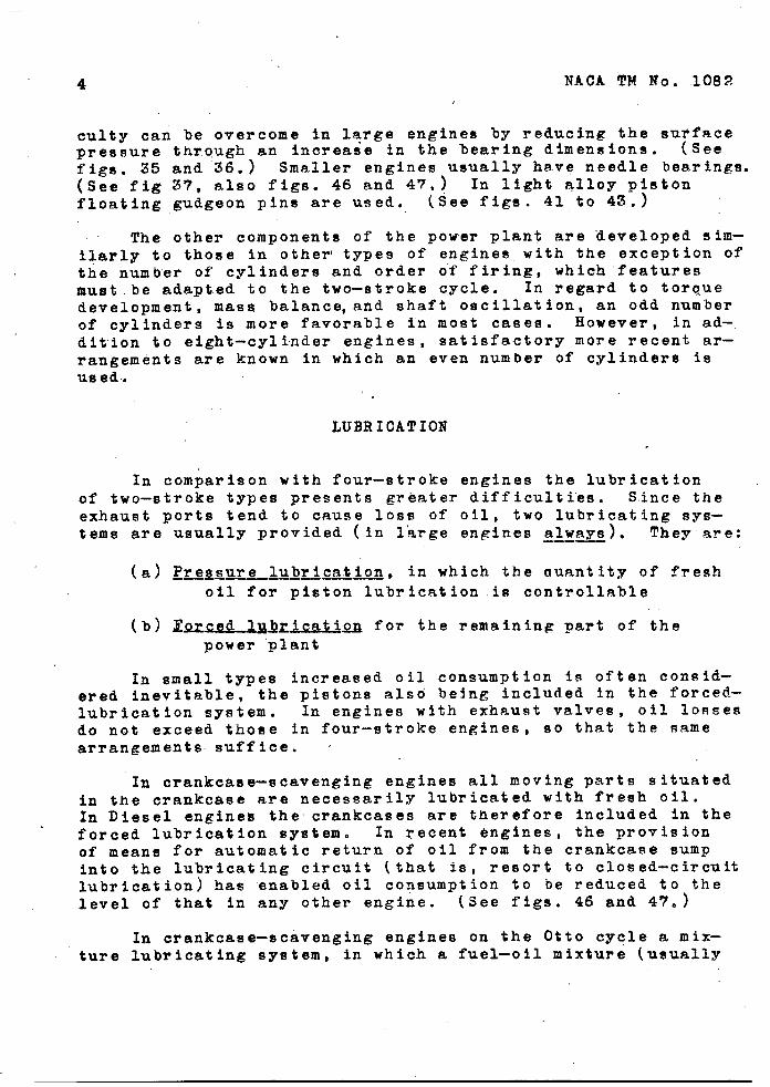
The most frequent material for cylinders (or liners) iscast, iron, although steel is aldo often employed. The materi-als used for pistons are cast iron, steel, and light alloys.In cast irdn and steel pistons is noted an increasing use ofscraper rings’ (more rarely slipper guides) which are rolledor hammered in. They are made of white metal or more freguent–ly of lead-bronze. (See figs. 33 to36,) The pistons are thenno longer stressed along their entirelength, and possible cylinderdistortion is conseo,uently prevented.
HEAT CONDITIONS IN THE PISTON
Heat conditions in the piston are primarily, influencedby the scavenging process. The flow of the exhaust gases of–ten causes an increase in temperature on one side of the pis-ton, and the scavenge air flow a temperature drop on the other.Piston crowns of high tensile strength are consequently re-~$:uired. (See figs. 33 and 34.)
Transmission of the heat accumulating in the piston crown

~-“.
><
,,
NAOA TM No . 1’082 3
to the coolant (cooling ‘water or oil) is a “problem which de-signers afe at present trying to solve In two totally differ-ent directions.
In the original ~n”~’”’old.erprinciple ‘the heat is conductedto the piston rings and ‘the heat flow to them aided by liberslcross sections. (See figi. 33.and 34.) If the thermal load-ing is not too high, ‘this method is a’dequate. In highlystressed en~ines, however, and also in opposed- and timing-piston engines where, the pistons are on the exhaust side, the,problem becomes considerably more difficult since the pistonrings naturally tend to stick.
As in four-stroke engines, more recent designs, ,however,appear to follo”w an alternative principle, by which the majorpart of the abstracted heat is kept away from the piston ringsso as to maintain their temperature ag low as possible. Toachieve this, the heat flow to the rings is therefore impededby suit’ably reducing the ring cross section or providing cast-on carrier rings. The principle is thus, to conduct the heataccumulating in the piston crown eitherdirectlv to the circulating-—-- --Aoil or indirectl~ through the piston skirt to the cylinder and.--——-circulatfng oil, bypassing the rings. This implies a much sire- ,pier method of piston cooling, which is clearly illustrated infigure 37.
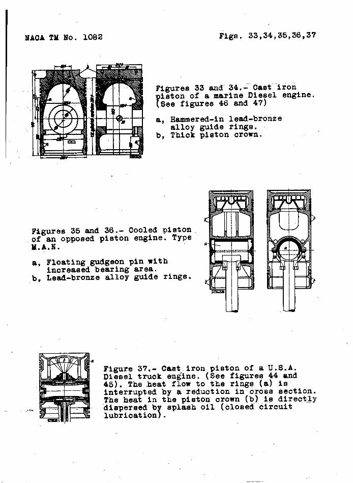
Another method consists of relieving the heat stresses onthe piston rings by preceding packing rings designed to preventseizing. The so-called “gas seal’t (fig. 30) is the most commonexample of this, although other types have also been suggested.(See-fig. 39.)
Finally, shields of heat-resisting steel are used (fig. 38).They can support higher working temperatures, so that the dropin temperature between.the gas and.the piston, and consequentlythe amount of heat to be abstracted from the piston are reduced..
Large or heavily heat-loaded pistons, as well as the pistonsof all opposed piston engines must be completely cooled, (Seefigs. 35 and 36.) The’ coolant” used is usually oil. Fresh wateris used ‘more seldom while air cooling has also been suggested(fig. ‘39). The coolant is conducted through jointed or tele-scopic pipes. Different methods of adapting. the connecting rodfor this purpose are being studied. .
,-:,. . .. . .. . . . .,*J -
The piston gudgeon’’pin~’ run without alternation of “pressure.Consequently, it’ is particularly difficult to feed the lubricantto the sliding surfaces at high bearing pressures. This diffi-
4 NACA TM No. 1085!
culty can be overcome fn large engines by reducing the surfacepressure through an increase in the hearing dimensions. (Seefign. 35 and”36. ) Smaller engines u~ually have needle bearings.(See fig 3?, also figs. 46 and 47. ) In ligh;1@;~o~3p;stonfloating gudgeon pins are used. (See figs. .
,. The other components of the power plant are developed sim-ilarly to those in other’ types of engines, with the exception ofthe number of cylinders and order of firing, which ’featuresmust .be adapted to the two-stroke cycle. In regard to torquedevelopment, mass balance, and shaft oscillation, an odd numberof cylinders is more favorable in most cases. Eowever, in ad-,dition to eight-cylinder engines, satisfactory more recent ar-rangements are known in which an even number of cylinders isused.
LUBRICATION
In comparison with four-stroke engines the lubricationof two-stroke types presents greater difficulties. Since theexhaust ports tend to cause 10SS of oil, two lubricating sys-tems are usually provided (in l“arge engines alw~). They are:---
(a) ~~w~~brication, in which the ouantity of fresh———-oil for piston lubrication is controllable
(b) luced~ybricatio~ for the remaining part of thepower “plant
In small types increased oil consumption is often consid-ered inevitable, the pistons also be$ng included in the forced-lubrication system. In engines with exhaust valves, oil lossesdo not exceed those in four-stroke engines, so that the samearrangements suffice. o
In crankcase-scavenging engines all moving parts situatedin the crankcase are necessarily lubricated with fresh oil.In Diesel engines the crankcases are therefore included in theforced lubrication system. In recent engines, the provisionof means for automatic return of oil from the crankcase sumpinto the lubricating circuit (that is, resort to closed-circuitlubrication) has ‘enabled oil consumption to be reduced to thelevel of that in any other engine. (See figs. 46 and 47.)
In crankcase-scavenging engines on the Otto cycle a mix-ture lubricating system, in which a fuel-oil mixture (usually

~NACA TM” NO. 1082 5!
in 20:1 ratio) is introduced into the carburetor, is commonlyused. The oil collecting in the crankcase is used for lubri-cating the transmission mechanism. This is a very effectivemethod$ but the oil consumption is necessarily high.’ It iS,,howeve,r.,,de.tx!.imeatalto, export prospects”, such fuel-oil mix–
,,.,
tures usually being unobtainable at foreign filling stations.Fuel injection and the substituted gaseous fuels require dif-ferent types” of lubrication. Some of these appear promising(“fig. 57, reference 68) and will be discussed in part 3 ofthe present p“aper.
—
GENERAL LAYOUT OF !CHE TWO-STROKE ENGINE
In general design ’engines with simple pistons are simi-lar to other. types. The practice of using separate cast orwelded frames, in which the stress is taken up by tie rods,is always ’found.in large engines (fig. 401) and occasionallyin smaller types. In two-stroke engines, particularly, thisform of construction is capable of fullest and most effectivedevelopment , and results in pleasing and effective designs.Smaller and medium-size engines are usually fitted with con-tinuous cast cylinder blocks extending to the.cylinder tops,placed on a bed plate (references ‘7?’,80, 99, 100, 102, 104,105, 107, 109, 110, 111, and 113). The stresses are usuallytaken. up by tie rods while the cylinder liners,are separatelyfitted. This type of engine represents a stepping stone tothe specifically automobile engine (figs. 41 to 45) Of
in-line or V-type, which is essentially similar to the four-stroke engine (references 74 to 76, 78, 79, 83 to 83, 103,and 112). Tie rods are often omitted in this case, however,the bed plate being formed by the oil sump and separate bear-ing caps.
Small and medium types of crankcase-scavenged Diesel en-,gines have crankcases fitted with separate cylinders, thecrankcase stresses being taken up by tie rods. (See figs. 46and 47. )
,
The o~sed-piston and timi~niston’ engines (references-—- —— -- --—---- —-85 to 98), on the other hand, often show considerable deviationfrom this standard design since their entire construction must,of course, be adapted to the special conditions. The’ Doxfordengines shown in figures 48 to 49, the mo8t po,p,ulartype of
;... large opposed-piston’,Dies’el” en’~ine faithfully adhere to theJunkers system of construction (references 91, 92 and 95), whilethe Junkers engine itself, which is now-a-days built only in
II .1

6 ‘NACA 9M” No,, 1082.
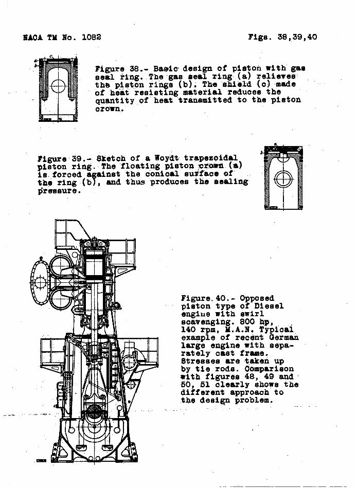
smaller sizes, tends to develop” along more economical and com-pact lines. In, opposed- and timing-piston engines are furtherfound all possible variants, of which the figures 50 to 56give ‘an approximate idea. The general impression is .of an un-certain and transitional developmexit. Only in small, high-speed. spark-ignition engines (e.g. , figs. 55 and 56) has “thetwin-parallel piston arrangement been standardized, partly, ‘perhaps, because the general laybu% need differ on’ly slightlyfrom that of standard-piston engines.
Translation ‘byJ. Helledoren
NACA TM NO. 1082 Figs . 33,34,35,36,37
Figures 33 and’34.= Cast”’”i~oh..
?iston of a marine Diesel engine.See figures 46 and 47)
a, Hammered-in lead-bronzealloy guide rings.
b, Thick piston crown.
F&8ures 35 and 36.- Cooled pistonof an opposed piston engine. TypeM.A.N.
a, Floating gudgeon pin withincreased bearing area.
b, Lead-bronze alloy guide rings.
a
_,-
UA UJ
Figure 37.- Cast.iron piston of a U.S.A.Diesel truck engine. (See figures 44 and45). The heat flow to the rings (a) isInterrupted by a reduction in cross section.,The.heat in the piston crown (b) is direct..lydispersed b
Tsplash oil”(closed circuit
lubrication .
MACA TM No. 1082 Figs . 38,39,40
.. ?.*.
Figure 38.- Ba8i~ design of piston with gasseai ring..Thp“gas seal ring,(a) reliavesthe p+qt.onrings (b);The “shield(o) madeof heat resisting material reduoes the
, quantity,of heat.transmitted to the pi8toa
& Ommn,.
Figure 39. - Sketc$h of a Woydt trapezoidalpiston ring. The float$.ngPiston ~~~ (a)is.,foroeda ainst the oonical su~?kce of’
fthe ting(b , and thus produoes the sealingpre8suri9.
.*.
l’igure.40.-Opposedpiston type c?fDieselengine with swirlscavenging. 800 4P,140 rpm, ‘U.A.N.TypiCtil,exagple of recdnt Germanlarge engine with.sepa-rately cast frame?Stresses are “takenupby tie rods. Comparisonwith figures 48, 49 and50, 51 clearly shows thedifferent approaoh tothe desiq problem. .-.,.,-

8;
Figures 41 to 43.- Twelve-cylinderV engine, 1200 hp, 700 rpm, Klockner- .Humboldt-Deutztype. 220 mm bore, 330 mm stroke, mechanicallydriven : ;centrifugalblower, swirl scavenging,fuel injection.Latest German marineand automobileengine. For comparison see corresponding~.S.A. engine infigures 52, 53.

}’
lTACATM MO. 1082 Figs. 44,45,46,4?
b -’mu
Figures 44 and 45.- Diesel engine with 27.5 hp per cylinderat 2000 rpm. General Motors Oo. 100 mm bcme, 127 mm stroke.Built as three, four and six-cylinder in-line engine. Uniflowscavenging, exhaust valves, mechanically driven Roots scaveng-ing blower with helical blades.
Blgures 46 and 47.- Marine Diesel engine of 50 hp per cylinderat 325’rpm. Hanseatische’Mot.orengesellschaft,Hamburg-Bergedorf.,~50 mm bore, 35’0mm stroke. Improv6d German orank=ease scavenging. $.eparateCylinders. Orankcase #tresses takenup by tie rods. A mep of 4 a$m 18 obtained *ith satisfactoryfuel consumption (17? to 175 g2/hp) and low oil consumptitmlittle over 2,gr).

?.6.
‘l!lACATM MO. 1082 Figs . 48,49,50,’51
ti P ‘m *[*
r: %11 I 1111 II [ 1111 Im
?igures 48 and 49.- 5-cylinder opposed piston engine. 8000 hp,133 rpm, 725 mm bore, 1300+950 mm stroke. A popular Britishmarine engine which has recently also gone into production inU.S.A. The original Junkers desi~without change.
1
Figures 50 and 51.- Latestdesign of double-actingengine with timing piston.1100 hp per cylinder at125 rpm. Burmeister andWain type. 550 mm bore,1200 mm piston stroke, 400mm timing piston stroke.The timing pistons (a) aredirectly driven from the
[crankshaft d) by theeccentrics b) and geartrain (c). Diameter oftiming piston equalsdiameter of working piston.
.,:, . ... ...>..--- .. ---- ..”
has-been retairiedpractically;-.fl._.7
d:
II_ .—-.
I
NACA TM NO. 1082 Figs. 52,53,54,55,58
..
Figures 52 and 53.- 800 hp opposed piston engine,~720 rpm.Fairbanks-Morse type. Mechanically driven Root centrifugalblower. -3O3mm bore, 254+254 mm stroke. Rail car andmarine engine. Copying the Junkers aero engine.
Figure 54.-Transm&8siOhgear of anopposed pistonengine.Dankworth type.Similar enginesare built byJunker8-Allaoh.,Sulzer,Oappa.,. ,...—.. .,..-, - ~ ~u H$ll.
g*.e+~, ’55~’ *O.’ .~o-swroke r~ing engine. UR,25Q type of,Auto=.Uniog ’date@ 1938.”Separate rociproca$ing’blower,of whiohtkq.~tston.~’&ie Ur$96tI by the ’orankehaftthrough the
/]6@8~trtp8 b . Znlst’pdrtq controll~by louvres .(o),tq$a-pistoti‘type.
●

1 ATI- 7183 . TITLE: Recent Development of the Two-Stroke Engine
(None) AUTHOR(S) : Zeman, J. ORIG. AGENCY: (Not known)
OQIO. A05MCT HO.
(None) PUBLISHED BY : (Not known) PU3USWM AOOCT NO.
(None) DAlt
(None) HOC CWL
Unclass. Germanv lAHOUAOa
German PAOSS
1 tUagra FOREIGN TITLE: (Original document not available)
TRANSLATION BY: National Advisory Committee lor Aeronautics. Washington. D. C. NO: TM 1082 ABSTRACT:
General design of two-stroke cycle engine and problems encountered are outlined. Scavenger and exhaust ports must be carefully arranged to keep heat distribution uniform. Materials most frequently used in manufacturing are cast iron for cylinders, cast iron or steel or light steel alloys for pistons, and lead-bronze for rings. Heat conditions In the piston head are discussed, and methods for attaining good heat distribution are explained. Lubrication difficulties are analyzed.
DISTRIBUTION: SPECIAL. All requests for copies must be addressed to: Translating Agency DIVISION: Power Plants, Reciprocating (6) SECTION: Design and Description (15)
ATI SHEET NO.: R-6-15-10
SUBJECT HEADINGS: Engines - Design (32864); Engines, Two stroke cycle (34190); Engine performance (32846)
Control Air Documents Ontco Vyright-Pattortoa Air Form Qaso, Dayton, Ohio
AIR TECHNICAL INDEX