piston engines part 4 piston engine operations (oil and fuel pumps)
TRANSCRIPT
PISTON ENGINES
Part 4
Piston Engine Operations(Oil and Fuel Pumps)
IntroductionOil Systems
Lubrication is used between 2 sliding surfaces to overcoming friction,
and therefore prevent or reduce component wear.
The properties demanded from a lubricantvary considerably with the particular application.
Lubricant for a bicycle is not suitable for a steam engine;a lubricating oil for any engine
should be of a suitable viscosity for maximum loadsand also retain this viscosity
over the full range of engine temperature.
Engine Block
SUMP
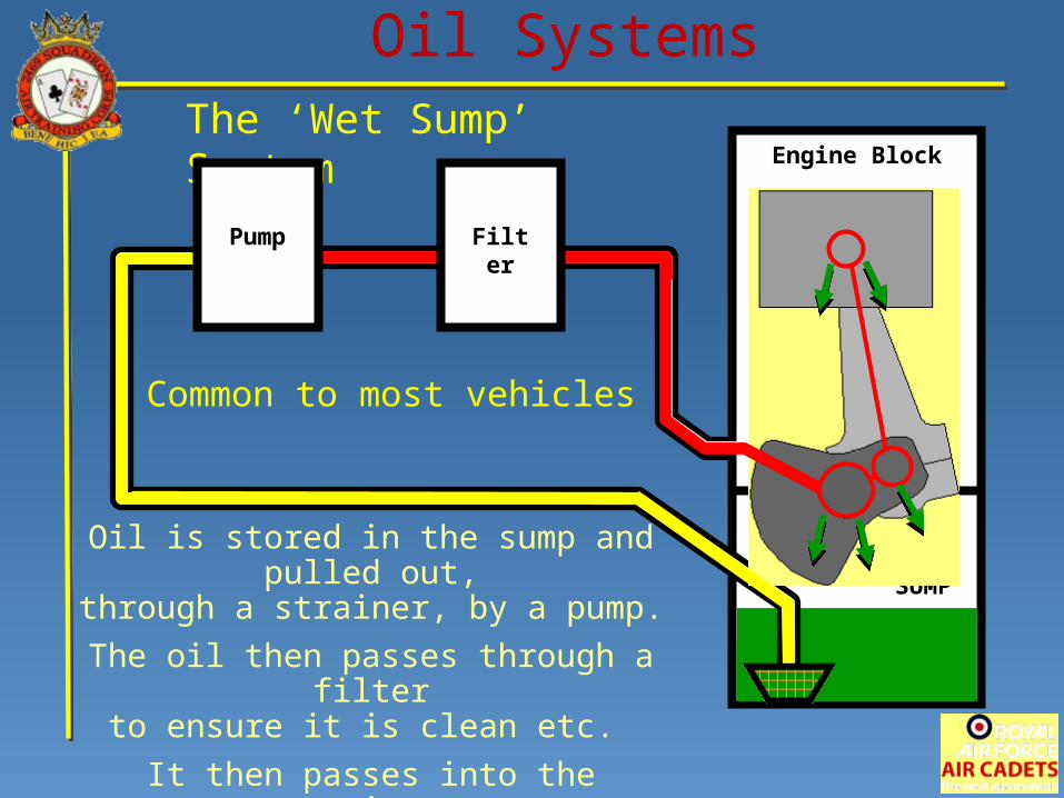
Oil SystemsThe ‘Wet Sump’ System
Common to most vehicles
FilterPump
Oil is stored in the sump and pulled out,through a strainer, by a pump.
The oil then passes through a filterto ensure it is clean etc.
It then passes into the engine,returning excess oil to the sump.
Engine Block
SUMP
Oil Systems
FilterPump
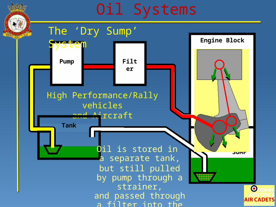
High Performance/Rally vehiclesand Aircraft
Tank
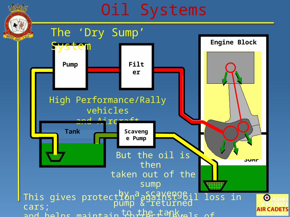
The ‘Dry Sump’ System
Oil is stored in a separate tank,
but still pulled by pump through a strainer,
and passed through a filter into the engine,
returning excess oil to the sump.
Engine Block
SUMP
Oil Systems
FilterPump
High Performance/Rally vehiclesand Aircraft
Tank Scavenge Pump
The ‘Dry Sump’ System
But the oil is then taken out of the sump by a scavenge pump &
returned to the tank,hence the name ‘Dry
Sump’This gives protection against oil loss in cars;and helps maintain correct levels of lubrication in aircraft.
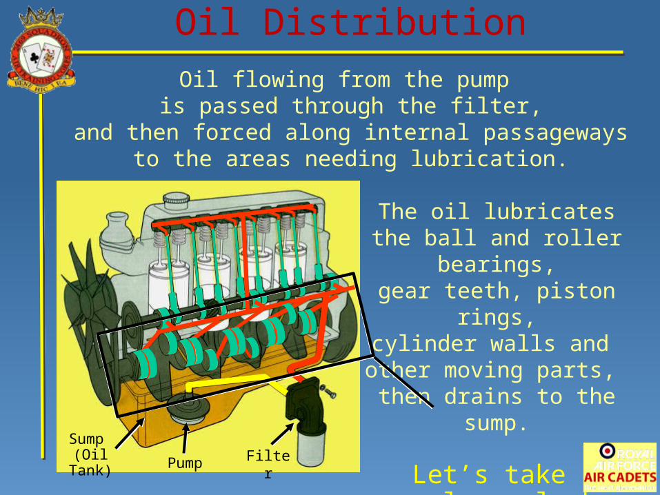
Oil flowing from the pump is passed through the filter,
and then forced along internal passagewaysto the areas needing lubrication.
The oil lubricatesthe ball and roller bearings,
gear teeth, piston rings,cylinder walls and
other moving parts, then drains to the sump.
Let’s take a closer look here.
Oil Distribution
Sump (Oil Tank)
Pump Filter
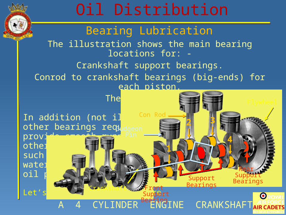
The illustration shows the main bearing locations for: -Crankshaft support bearings.
Conrod to crankshaft bearings (big-ends) for each piston.The gudgeon pins.
In addition (not illustrated) areother bearings required to provide smooth running of other componentssuch as the cam shaft, water pump drive shaft,oil pump drive shaft etc.
Let’s take a closer look here.
Oil DistributionBearing Lubrication
Flywheel
Front Support Bearing
Rear Support BearingsSupport
Bearings
Gudgeon Pin
Crankshaft
Con Rod
A 4 CYLINDER ENGINE CRANKSHAFT
1
2 3
4
Con Rod Big End
Oil DistributionBearing Lubrication
Crankshaft
Shell Bearings
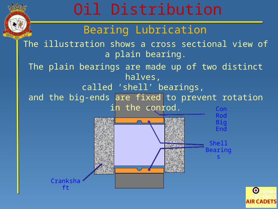
The illustration shows a cross sectional view of a plain bearing.
The plain bearings are made up of two distinct halves, called ‘shell’ bearings,
and the big-ends are fixed to prevent rotation in the conrod.
Con Rod Big End
Oil Splash
Oil Splash
Oil Splash
Oil Splash
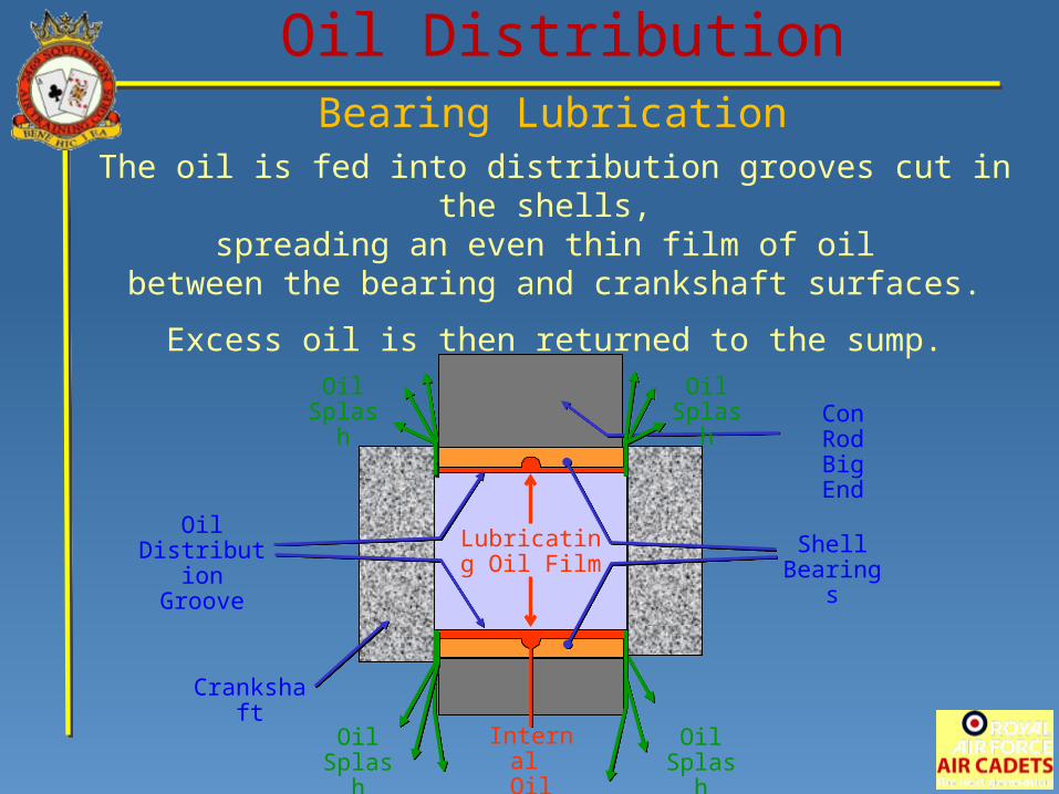
Oil DistributionBearing Lubrication
Crankshaft
Oil Distribution
Groove
Internal Oil Feed
Lubricating Oil Film
Shell Bearings
The oil is fed into distribution grooves cut in the shells, spreading an even thin film of oil
between the bearing and crankshaft surfaces.
Excess oil is then returned to the sump.
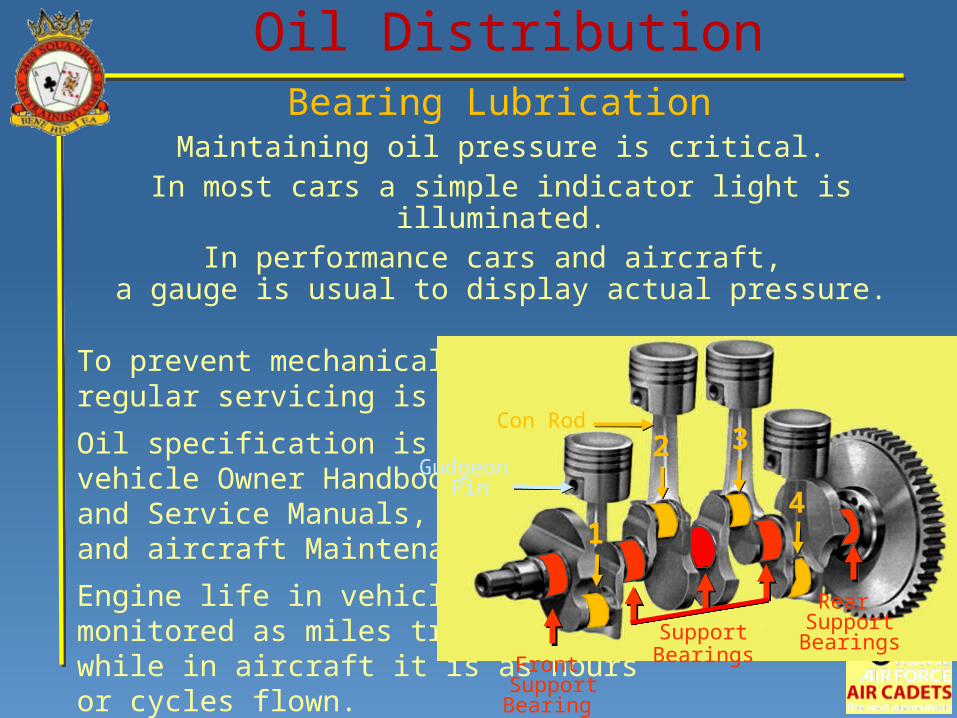
Maintaining oil pressure is critical.In most cars a simple indicator light is illuminated.
In performance cars and aircraft, a gauge is usual to display actual pressure.
To prevent mechanical damage regular servicing is necessary.
Oil specification is found invehicle Owner Handbooksand Service Manuals, and aircraft Maintenance Manuals.
Engine life in vehicles ismonitored as miles travelled, while in aircraft it is as hours or cycles flown. Front
Support Bearing
Rear Support BearingsSupport
Bearings
Gudgeon Pin
Con Rod
1
2 3
4
Oil DistributionBearing Lubrication
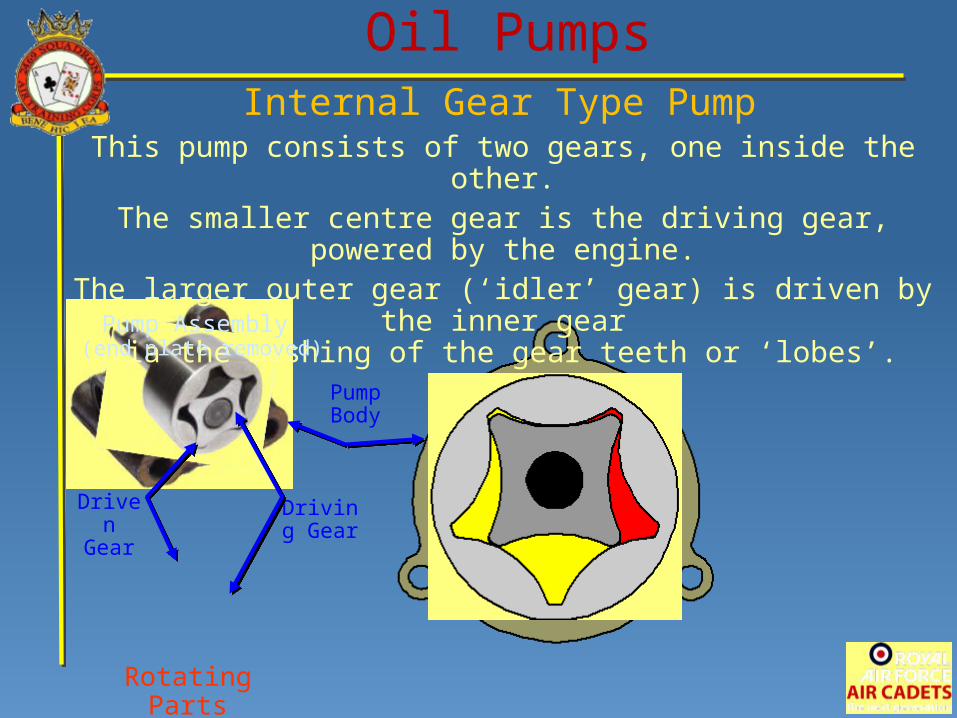
Oil PumpsInternal Gear Type Pump
Rotating Parts
Driving Gear
Pump Body
This pump consists of two gears, one inside the other.The smaller centre gear is the driving gear, powered by the engine.
The larger outer gear (‘idler’ gear) is driven by the inner gearvia the meshing of the gear teeth or ‘lobes’.
Pump Assembly (end plate removed)
Driven Gear
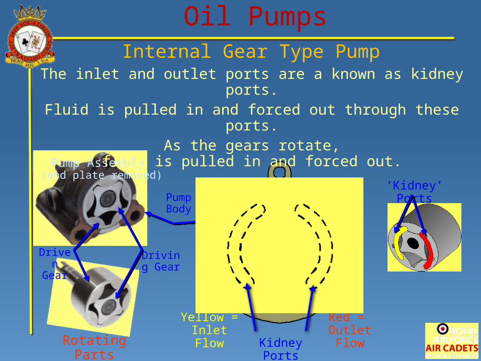
Oil PumpsInternal Gear Type Pump
Pump Assembly (end plate removed)
Rotating Parts
Driving Gear
Driven Gear
Pump Body
Yellow = Inlet Flow
Red = Outlet Flow
‘Kidney’ Ports
The inlet and outlet ports are a known as kidney ports.Fluid is pulled in and forced out through these ports.
As the gears rotate,fluid is pulled in and forced out.
Kidney Ports
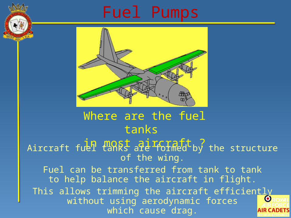
Fuel Pumps
Where are the fuel tanks in most aircraft ?
Aircraft fuel tanks are formed by the structure of the wing.Fuel can be transferred from tank to tank
to help balance the aircraft in flight.This allows trimming the aircraft efficiently
without using aerodynamic forceswhich cause drag.
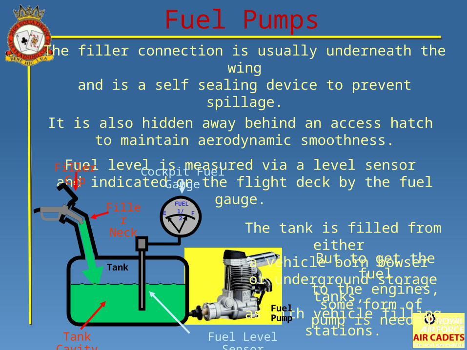
The filler connection is usually underneath the wingand is a self sealing device to prevent spillage.
It is also hidden away behind an access hatch to maintain aerodynamic smoothness.
Fuel level is measured via a level sensor and indicated on the flight deck by the fuel gauge.
The tank is filled from either a vehicle born bowser
or underground storage tanks, as with vehicle filling stations.
Tank
E F1/2FUEL
Fuel Pumps
Tank Cavity
Filler Cap
Filler Neck
Fuel Level Sensor
Cockpit Fuel Gauge
But to get the fuelto the engines,some form of
pump is needed.FuelPump
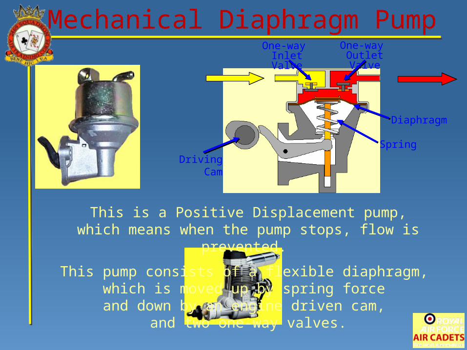
Mechanical Diaphragm PumpOne-way Inlet Valve
Diaphragm
One-way Outlet Valve
Driving Cam
This is a Positive Displacement pump,which means when the pump stops, flow is prevented.
This pump consists of a flexible diaphragm, which is moved up by spring force
and down by an engine driven cam, and two one-way valves.
Spring
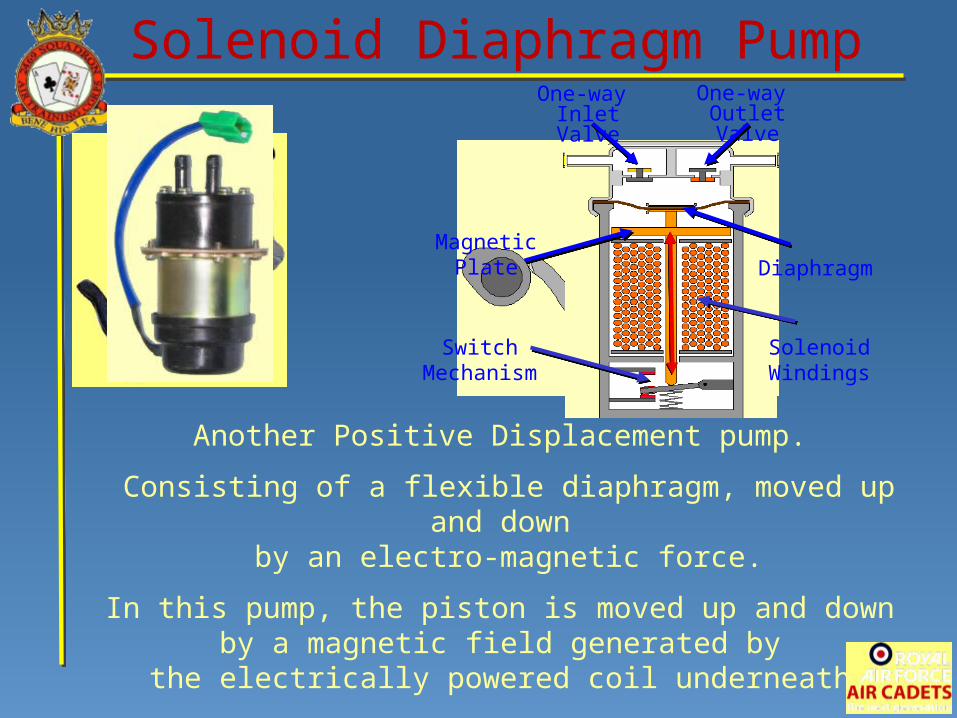
Solenoid Diaphragm PumpOne-way Inlet Valve
One-way Outlet Valve
Diaphragm
Solenoid Windings
Magnetic Plate
Switch Mechanism
Another Positive Displacement pump.
Consisting of a flexible diaphragm, moved up and down by an electro-magnetic force.
In this pump, the piston is moved up and down by a magnetic field generated by
the electrically powered coil underneath.
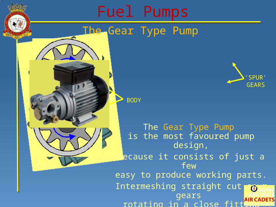
Fuel PumpsThe Gear Type Pump
‘SPUR’ GEARS
BODY
The Gear Type Pump is the most favoured pump design,because it consists of just a few easy to produce working parts.
Intermeshing straight cut spur gears rotating in a close fitting body.
FLOW OUT
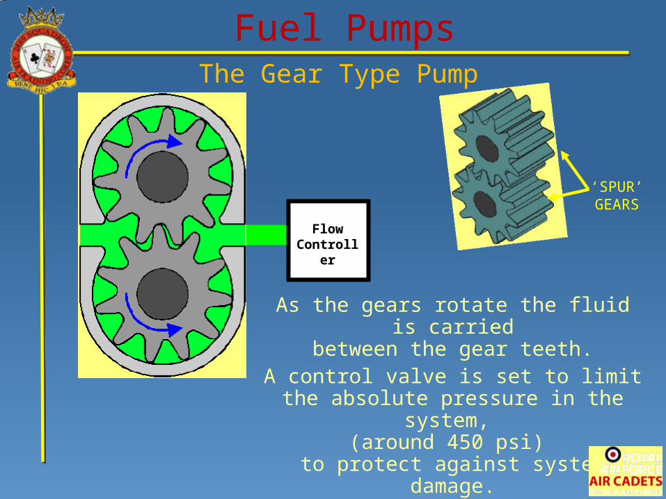
Fuel PumpsThe Gear Type Pump
‘SPUR’ GEARS
Flow Controller
As the gears rotate the fluid is carriedbetween the gear teeth.
A control valve is set to limit the absolute pressure in the system,
(around 450 psi) to protect against system damage.
FLOW OUT
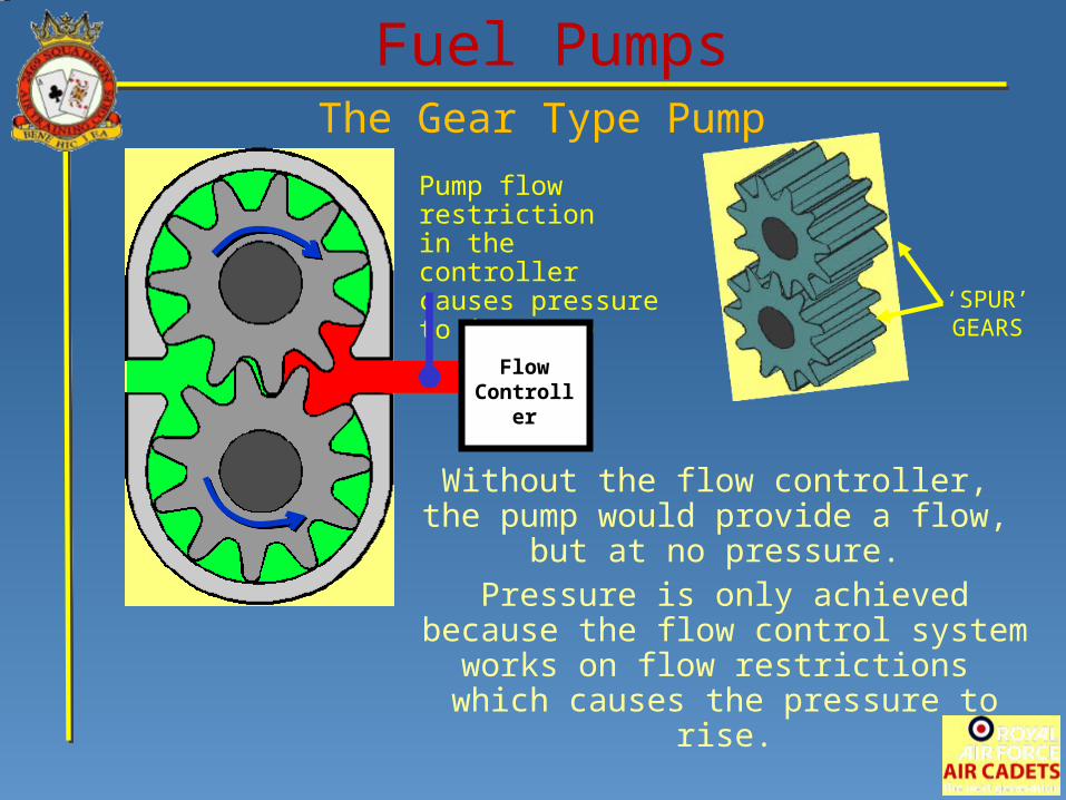
Fuel PumpsThe Gear Type Pump
‘SPUR’ GEARS
Pump flow restrictionin the controllercauses pressureto increase
Flow Controller
Without the flow controller, the pump would provide a flow,
but at no pressure. Pressure is only achieved
because the flow control system works on flow restrictions
which causes the pressure to rise.
Carburettor
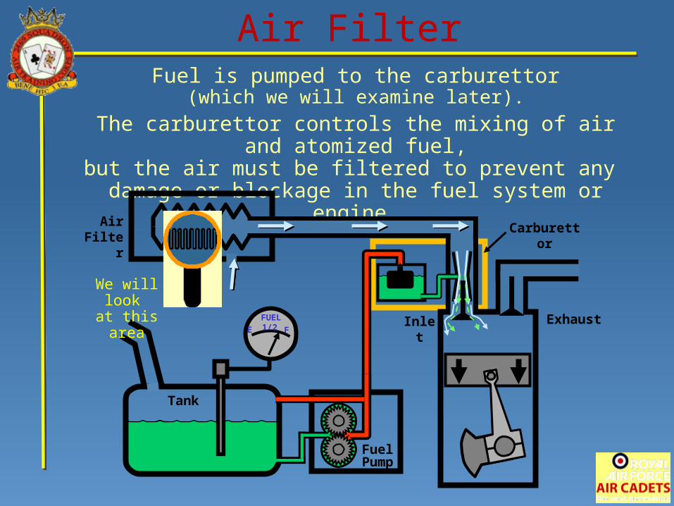
Air FilterFuel is pumped to the carburettor
(which we will examine later).
The carburettor controls the mixing of air and atomized fuel,but the air must be filtered to prevent any
damage or blockage in the fuel system or engine.
Tank
E F1/2FUEL
FuelPump
Air Filter
Inlet Exhaust
We will look at this area

Air Filter
Air FilterA paper based element bonded into a rubberized material,
is concertinaed to get the greatest surface area.
Air with contaminants passes through the filter, which catches the contaminants and leaves the air cleaner.
Filtration rate is in Microns (1 micron = 0.000,001 metre). So a 30 micron filter
stops particles of 30 microns or more.
Filter of corrugated paper
Air and Dirt
Dirt trapped by filter
Clean Air
Check of Understanding
Where would a Dry Sump Oil Systembe most commonly used?
Only inHigh Performance/Rally vehicles
Most vehicles
Only in Aircraft
High Performance/Rally vehiclesand Aircraft
What differentiates a Dry Sump systemfrom a Wet Sump system?
A Scavenger Pump
A Diaphragm Pump
A Positive Displacement Pump
An Internal Gear Type Pump
Check of Understanding
Bearings in a crankshaft are made up of two distinct parts.
What are these called?
Ball Bearings
Dry Bearings
Shell Bearings
Roller Bearings
Check of Understanding
Where would you find the oil specificationsfor an aircraft?
The aircraft log
The service manual
The operating manual
The maintenance manual
Check of Understanding
Within an internal gear-type pump there are two gears.
Which one is driven by the engine?
The Driven Gear
The Idler Gear
The Outer Gear
The Driving Gear
Check of Understanding
Which of these pumps has a flexible diaphragm moved up and down
by an electro-magnetic force?
A Solenoid Diaphragm Pump
A Gear Type Pump
A Scavenger Pump
A Mechanical Diaphragm Pump
Check of Understanding
Which is the most favoured type of pump design?
Meshing Gear Pump
Solenoid Diaphragm Pump
Mechanical Diaphragm Pump
Gear Type Pump
Check of Understanding
Without the flow controller in a gear-type pump,
What flow would the pump supply?
No flow at all
A flow at no pressure
A flow at high pressure
A flow at low pressure
Check of Understanding
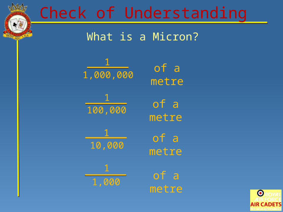
What is a Micron?
Check of Understanding
of a metre1
100,000
11,000,000
of a metre
110,000
of a metre
1
1,000of a metre
PISTON ENGINES
End of Presentation