3. scope of supply 1.1 scope of supply by cpstl
TRANSCRIPT
3. SCOPE OF SUPPLY
1.1 Scope of Supply by CPSTL
2.1.1 Construction Utilities
3.1.1.1 Electricity and drinking water that would be supplied to the contractor to undertake this work would be charged from the contractor as per meter/estimate .The prospective contractor is required to indicate his requirements of power from the CPSTL in his offer for evaluation purposes.
3.1.1.2 The electrical power supply available to the contractor is 1000 Watts, 400V AC, 4 wire (TPN), 50Hz and shall be subjected to following 06 conditions.
3.1.1.3 The Electrical Section of CPSTL will terminate feeding cable to a suitable circuit isolating and interrupting devices such as a circuit breaker or a switch fuse at convenient location, within 100 ft. from the tank shell. This switch gears shall remain the property of CPSTL and contractor shall have no access to it.
3.1.1.4 It is the responsibility of the contractor to properly connect his main power distribution board to the downstream side of the CPSTL switch gear, in consultation / supervision of Electrical Engineer of CPSTL.
3.1.1.5 Contractor’s power distribution board should consist of adequate over current and earth leakage protective device for safety of men and machinery.
3.1.1.6 It is the responsibility of the contractor to maintain his switch gear and cable network in good condition, so as to provide, complete safety to men and machinery.
3.1.1.7 Power supply will be energized after inspection by the Electrical Engineer of CPSTL, provided all requirements in clause (2)and (3)are satisfied.
3.1.1.8 The whole electrical installation of the contractor shall conform to IEE wiring regulations (16th Edition) published by the Institution of Electrical Engineers (I.E.E), London.
1.2 Scope of Supply by Contractor
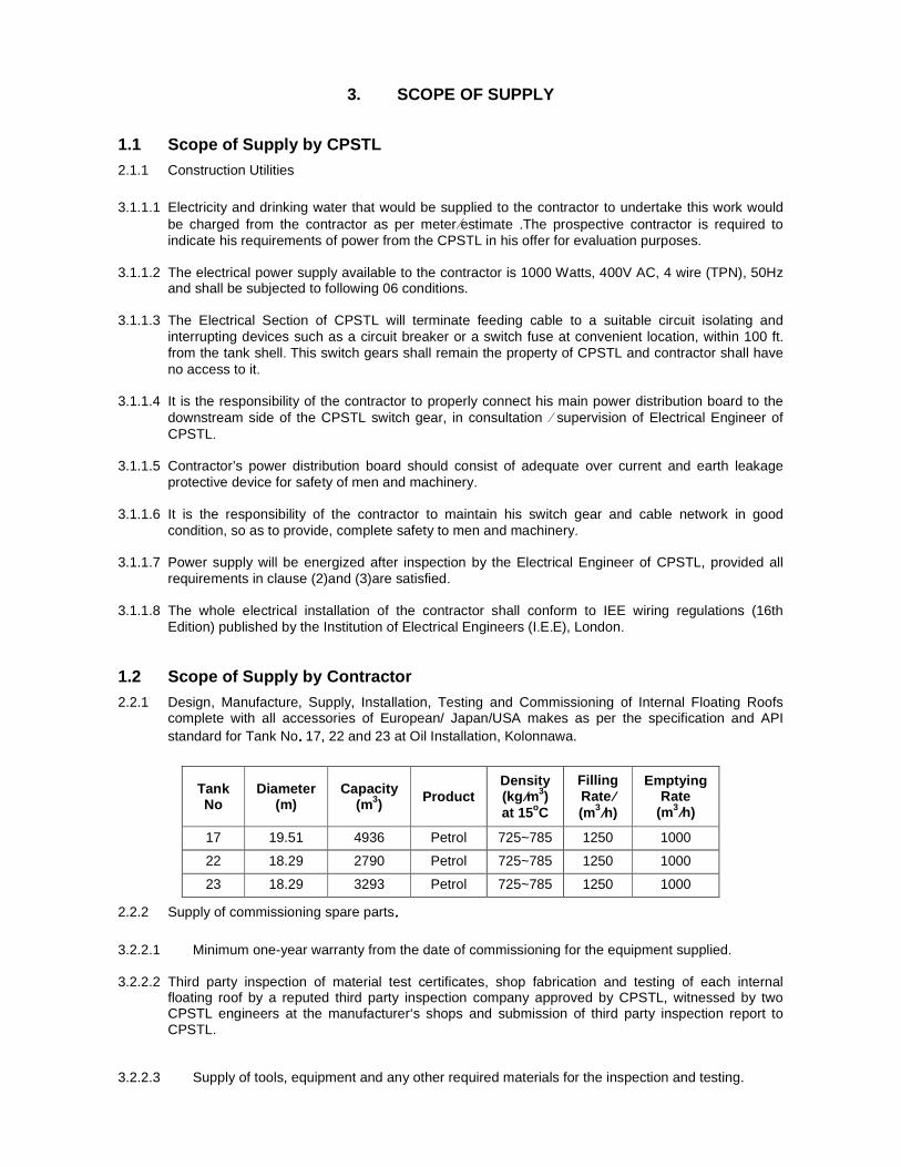
2.2.1 Design, Manufacture, Supply, Installation, Testing and Commissioning of Internal Floating Roofs complete with all accessories of European/ Japan/USA makes as per the specification and API standard for Tank No. . . . 17, 22 and 23 at Oil Installation, Kolonnawa.
2.2.2 Supply of commissioning spare parts....
3.2.2.1 Minimum one -year warranty from the date of commissioning for the equipment supplied.
3.2.2.2 Third party inspection of material test certificates, shop fabrication and testing of each internal floating roof by a reputed third party inspection company approved by CPSTL, witnessed by two CPSTL engineers at the manufacturer‘s shops and submission of third party inspection report to CPSTL.
3.2.2.3 Supply of tools, equipment and any other required materials for the inspection and testing.
Tank No
Diameter (m)
Capacity (m3) Product
Density (kg /m3) at 15oC
Filling Rate/
(m3/h)
Emptying Rate
(m3/h)
17 19.51 4936 Petrol 725~785 1250 1000
22 18.29 2790 Petrol 725~785 1250 1000
23 18.29 3293 Petrol 725~785 1250 1000

Page 1 of 46
3.2.2.4 Supply of as built detailed drawings, all test certificates, and duly furnished manufacturing data sheets along with the internal floating roofs.
3.2.2.5 Supply of installation, operation, workshop and spare parts manuals in English Language.
3.2.2.6 Internal Floating Roofs components suitably protected for transportation and suitable for abnormal weather conditions .
3.2.2.7 Supply of Internal Floating Roof erection procedure.
3.2.2.8 Supply of procedure for observing any seal damage during operations.
3.2.2.9 Supply of food, accommodation, internal transportation, any other local expenses for two CPSTL Engineers witnessing the testing and inspection at the manufacture‘s testing facility. Chargers for return air tickets and visa for CPSTL Engineers will be borne by CPSTL.
3.2.2.10 Training of CPSTL maintenance crew for preventive maintenance, trouble shooting and repairing at the work shop of CPSTL, Sri Lanka.

Page 2 of 46
4. SCOPE OF WORK AND SPECIFICATIONS
2.1 Scope of Work by CPSTL
3.1.1 Necessary modification for the tanks to install internal floating roof in fixed roof tanks shall be attended by other party.
3.1.2 Only one modified Tanks will be released for the installation of IFR at an instance.
3.1.3 Next tank will be released for IFR installation approximately within 3 months from the completion, testing and commissioning of the previous tank.
2.2 Contractors’ Scope of Work and Specifications
Scope of Work and Specifications for Design, Manufacture, Supply, Installation, Testing and Commissioning of Aluminium internal floating roofs (Metallic Roofs on floats) are as follows.
3.2.1 Scope of Work
3.2.1.1 Design, Manufacture, Supply, Installation, Testing and Commissioning of Aluminium internal floating roofs on floats have their deck above the liquid supported by closed pontoon compartments for buoyancy as per API STANDARD 650 Appendix H Section H.2.2 e inside the Fixed Roof Tank (Refer Table No. 01 for details) to minimize breathing losses and thereby reduce the overall Hydrocarbon loss from the tank.
3.2.1.2 The Bidder shall also carry out the jobs that are not specifically mentioned in this specification here but required for successful completion of the job in all respects as per the standards, drawings and codes. Loading, handling and transportation of all materials from supply point/store at work site/Contractor’s store as per the requirement of the job.
3.2.1.3 It is desired that the provision of Aluminium Internal Floating Roof shall have minimum impact on safe filling capacity of the Tank.
3.2.1.4 Supplier shall study the drawings attached. A certificate for suitability of proposed Internal Floating Roofs shall be submitted to CPSTL.
3.2.2 Codes and standards • API Standard 650, Welded tanks for oil storage, 12th Edition, March 2013.
• API Standard 653, Tank Inspection, Repair, Alteration and Reconstruction, 5thEdition,
November2014
The applicable fabrication, erection, welding, inspection and testing requirements of Annex H of
API standard 650 shall be met.
3.2.3 Specification
4.2.3.1 Material
The Manufacturer shall submit a complete material specification in his proposal. The choice of
materials shall be governed by compatibility with the specified liquid. Material produced to
specifications other than those listed in API STANDARD 650 Annex. H (alternative materials) may
be used. Material shall be certified to meet all the requirements of a material specification listed in
API STANDARD 650 Annex H, and approved by the CPSTL or shall comply with requirements as
specified by the CPSTL.

Page 3 of 46
The material of floating roof is Aluminium. Aluminum shall conform to the requirements of API
STANDARD 650 Annex AL. Aluminum skin shall be 0.50 mm (0.020 in.) minimum nominal
thickness. Extruded Aluminum floats shall be 1.2 mm (0.050 in.) minimum nominal thickness.
Peripheral rim section shall be 3.0 mm minimum thickness.
4.2.3.2 General Requirements
a. An internal floating roof and its accessories shall be designed and constructed to allow the roof to
operate throughout its normal travel without manual attention and without damage to any part of
the fixed roof, the internal floating roof, internal floating roof seals (except for normal wear), the
tank, or their appurtenances
b. The internal floating roof shall be designed and built to float and rest in a uniform horizontal plane
(no drainage slope required).
c. All seams in the internal floating roof that are exposed to product vapor or liquid shall be vapor-
tight in accordance with API STANDARD 650 H.4.3.1.
d. A vapor-tight rim (or skirt), extending at least 150 mm (6 in.) above the liquid at the design
flotation level, shall be provided around both the internal floating roof periphery and around all
internal floating roof penetrations (columns, ladders, stilling wells, man ways, open deck drains
and other roof openings)except for drains designed to avoid product backflow onto the roof.
e. a vapor-tight rim (or skirt), extending at least 100 mm (4 in.)into the liquid at the design flotation
level, around both the internal floating roof periphery and around all internal floating roof
penetrations (columns, ladders, stilling wells, manways, open deck drains and other roof
openings), with the exception of penetrations for pressure-vacuum (bleeder)vents (per H.5.2.1).
f. All conductive parts of the internal floating roof shall be electrically interconnected and bonded to
the outer tank structure. This shall be accomplished by electric bonding shunts in the seal area (a
minimum of four, uniformly distributed)or flexible multi-strand cables from the external tank roof to
the internal floating roof (a minimum of two, uniformly distributed). All movable cover accessories
(hatches, manholes, pressure relief devices, and other openings)on the internal floating roof shall
be electrically bonded to the internal floating roof to prevent static electricity sparking when they
are opened.
g. Each closed flotation compartment shall be capable of being field-inspected for the presence of
combustible gas. Inspection openings shall be located above the liquid level and closed
compartments shall be capable of being resealed in the field after periodic inspection (to prevent
liquid or vapor entry).
h. All closed flotation compartments shall be seal welded to prevent liquid or vapor entry.
i. Deck Drains shall be provided to return any spillage or condensate to the product. Such drains
shall close automatically or extended at least 100 mm into the product to minimize the vapor loss.

Page 4 of 46
4.2.3.3 Buoyancy Requirements
a. All internal floating roof design calculations shall be based on the lower of the product specific
gravity or0.7 (to allow for operation in a range of hydrocarbon service),
b. All internal floating roofs shall include buoyancy required to support at least twice its dead weight
(including the weight of the flotation compartments, seal and all other floating roof and attached
components), plus additional buoyancy to offset the calculated friction exerted by peripheral and
penetration seals during filling.
c. The internal floating roof shall be designed to meet the requirements of API STANDARD 650
H.4.2.1.3 and to safely support at least two men walking anywhere on the roof while it is floating
or resting on its supports without damaging the floating roof and without allowing product on the
roof. One applied load of 2.2 kN(500 lbf)over 0.1 m2 (1 ft2)applied anywhere on the roof
addresses two men walking.
4.2.3.4 Internal Floating Roof Support Design Loads
Internal floating roof supports and deck structural attachments (such as reinforcing pads and
pontoon end gussets) shall be designed to support the load combinations listed in API STANDARD
650 H.4.2.2.2 without exceeding allowable stresses. Consideration shall also be made for non-
uniform support settlement or other non-uniform load distribution.
4.2.3.5 Other Design Requirements
Aluminum load carrying members, assemblies and connections shall comply with the design
requirements of the latest edition of the Aluminum Design Manual.
4.2.3.6 Joint Design a. All seams in the floating roof exposed directly to product vapour or liquid shall be welded,
bolted, screwed, riveted, clamped, or sealed and checked for vapour-tightness per API Standard 650 H.6.2.
b. Welded joints between aluminium members shall conform to API Standard 650, AL.5.1
c. Single-welded butt joints without backing are acceptable for flotation units where one side is inaccessible.
d. The thickness of fillet welds on material less than 4.8 mm (3/16 in.)thick shall not be less than that of the thinner member of the joint.
e. Only austenitic type stainless steel hardware shall be used to join aluminium components to each other or to carbon steel.
f. Manufacturer shall specify if aluminum hardware may be used to join aluminum components. Aluminum shall be isolated from carbon steel by an austenitic stainless steel spacer, an elastomeric pad, or equivalent protection. The use of plated fasteners shall be permitted only when connecting steel components.
g. Use of any joint sealing compound, insulating material, polymer, elastomer, or adhesive shall be preapproved by the CPSTL. The joining procedure along with test results demonstrating the properties required by this paragraph shall be described completely.
h. Any joint sealing compound, insulating material, elastomeric or adhesive shall be compatible with the product stored; specified service conditions; and with materials joined.
i. Resulting joints shall be equivalent in serviceability (with the basic floating roof components), of a size and strength that will accept the roof design loads without failure or leakage, and shall have an expected life equal to the service life of the roof. Any non-metallic component shall be selected and fabricated to preclude absorption (under design conditions specified and permitted by this standard)of hydrocarbons, hydro-test water and specified product to be stored.

Page 5 of 46
4.2.3.7 Peripheral Seals
a. In addition to the required floating roof primary peripheral seal, secondary peripheral seals shall
be provided.
b. A peripheral seal (rim seal) that spans the annular space between the internal floating roof deck
and the shell shall be provided. Peripheral seals shall be one mounted above the other, the
lower is the primary peripheral seal and the upper is the secondary peripheral seal.
c. Primary and Secondary seal material shall be able to use with gasoline(Fluoropolymers or Nitril)
d. All peripheral seals and their attachment to the floating roof shall be designed to accommodate
±100 mm (±4 in.) of local deviation between the floating roof and the shell.
Type of peripheral seal
a. Peripheral seals (Primary and Secondary) shall be Vapor-mounted rim seal in a form of
flexible-wiper seals.
Vapor-mounted rim seal means Peripheral seal positioned such that it does not normally
contact the surface of the stored liquid. Flexible-wiper seal means a rim seal utilizing a
blade or tip of a flexible material (such as extruded rubber or synthetic rubber) with or
without a reinforcing cloth or mesh.
b. The specific requirements for all floating roof peripheral seals are listed below.
1) All fasteners and washers for installation of seal joints, including fabric seal joints, shall
be austenitic stainless steel. (See restrictions on contact between galvanizing and
stainless steel in API STANDARD 650S.2.1.3.)
2) The seals shall be designed for a temperature range extending from design metal
temperature less 8 °C (15 °F)to the maximum operating temperature.
3) Lengths of seal sections shall be as long as practical. No holes or openings shall be
permitted in the completed seal. The seal material may be fabricated in sections
resulting in seams, but any such seam shall be joined or otherwise held tightly together
along the entire seam. For peripheral seals that use a fabric material to affect the seal,
the requirement in the preceding sentence applies only to the fabric and not to any
support devises. An adequate but minimum number of expansion joints shall be
provided.
4) Provisions shall be made to prevent damage to the seal due to any overflow openings in
the shell.
5) Rough spots on the shell that could damage the seal assembly shall be ground smooth.
See API STANDARD 650H.6.1.
6) All metallic components shall be electrically bonded. See API STANDARD 650H.4.1.6
or C.3.1.6 for electrical bonding requirements.
4.2.3.8 Roof Penetrations
Columns, ladders, and other rigid vertical appurtenances that penetrate the deck shall be provided
with a seal that will permit a local deviation of ±125 mm (±5 in.). Appurtenances shall be plumb
within a tolerance of ±75 mm (±3 in .).
Page 6 of 46
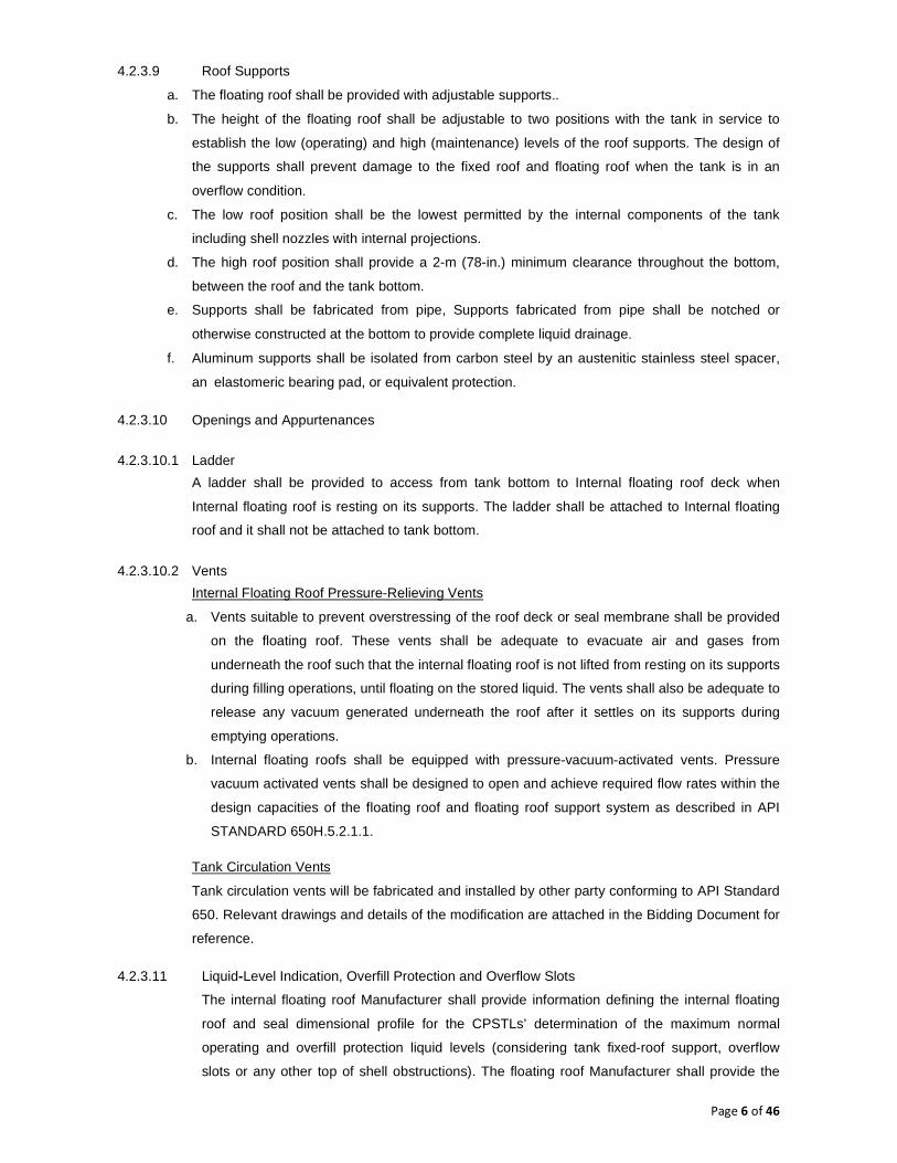
4.2.3.9 Roof Supports
a. The floating roof shall be provided with adjustable supports..
b. The height of the floating roof shall be adjustable to two positions with the tank in service to
establish the low (operating) and high (maintenance) levels of the roof supports. The design of
the supports shall prevent damage to the fixed roof and floating roof when the tank is in an
overflow condition.
c. The low roof position shall be the lowest permitted by the internal components of the tank
including shell nozzles with internal projections.
d. The high roof position shall provide a 2-m (78-in.) minimum clearance throughout the bottom,
between the roof and the tank bottom.
e. Supports shall be fabricated from pipe, Supports fabricated from pipe shall be notched or
otherwise constructed at the bottom to provide complete liquid drainage.
f. Aluminum supports shall be isolated from carbon steel by an austenitic stainless steel spacer,
an elastomeric bearing pad, or equivalent protection.
4.2.3.10 Openings and Appurtenances
4.2.3.10.1 Ladder
A ladder shall be provided to access from tank bottom to Internal floating roof deck when
Internal floating roof is resting on its supports. The ladder shall be attached to Internal floating
roof and it shall not be attached to tank bottom.
4.2.3.10.2 Vents
Internal Floating Roof Pressure-Relieving Vents
a. Vents suitable to prevent overstressing of the roof deck or seal membrane shall be provided
on the floating roof. These vents shall be adequate to evacuate air and gases from
underneath the roof such that the internal floating roof is not lifted from resting on its supports
during filling operations, until floating on the stored liquid. The vents shall also be adequate to
release any vacuum generated underneath the roof after it settles on its supports during
emptying operations.
b. Internal floating roofs shall be equipped with pressure-vacuum-activated vents. Pressure
vacuum activated vents shall be designed to open and achieve required flow rates within the
design capacities of the floating roof and floating roof support system as described in API
STANDARD 650H.5.2.1.1.
Tank Circulation Vents
Tank circulation vents will be fabricated and installed by other party conforming to API Standard
650. Relevant drawings and details of the modification are attached in the Bidding Document for
reference.
4.2.3.11 Liquid -Level Indication, Overfill Protection and Overflow Slots
The internal floating roof Manufacturer shall provide information defining the internal floating
roof and seal dimensional profile for the CPSTLs’ determination of the maximum normal
operating and overfill protection liquid levels (considering tank fixed-roof support, overflow
slots or any other top of shell obstructions). The floating roof Manufacturer shall provide the

Page 7 of 46
design flotation level (liquid surface elevation)of the internal floating roof at which the
pressure/vacuum relief vents will begin to open (to facilitate the CPSTLs’ determination of
minimum operating levels).
4.2.3.12 Anti-Rotation and Centering Devices
The internal floating roof shall be centred and restrained from rotating. A guide pole with
rollers, two or more seal centring cables or other suitable device(s)shall be provided as
required for this purpose. The internal floating roof shall not depend solely on the peripheral
seals or vertical penetration wells to maintain the centred position or to resist rotation. Any
device used for either purpose shall not interfere with the ability of the internal floating roof to
travel within the full operating elevations in accordance with API STANDARD 650H.4.1.1.
4.2.3.13 Manholes and Inspection Hatches
4.2.3.13.1 Shell Manholes
Two tank shell manholes above the internal floating roof resting position will be fabricated and
installed by other party conforming to API STANDARD 650. Relevant drawings and details of
the modification are attached in the Bidding Document for reference.
4.2.3.13.2 Internal floating roof deck manholes
Two internal floating roof deck manholes shall be provided for easy access to and ventilation
of the tank when the floating roof is on its supports and the tank is empty. The manholes shall
have nominal opening of 600 mm and shall be provided with a bolted or secured and
gasketed manhole cover.The manhole neck dimensions shall meet the requirements of API
STANDARD 650H.4.1.4 and H.4.1.5.
4.2.3.14 Inlet Diffuser
Tank Inlet Diffusers will be fabricated and installed by CPSTL conforming to API STANDARD
650. Relevant drawings and details of the modification are attached in the Bidding Document
for reference.
4.2.3.15 Gauging and Sampling Devices
Internal floating roof shall have provision to accommodate Stilling well for radar gauge
extending up to the fixed roof and Provision in the internal floating roof for taking manual
product level measurements using Dip Tape and Plumb.All such devices on the floating roof
shall be installed within the plumbness tolerance of H.4.5of API Standard 650.
Stilling well will be fabricated and installed by other party conforming to API standard650.
CPSTL will provide relevant drawings and details of the modification for reference
4.2.3.16 Foam Dams
Internal floating roof shall have installed Integral Foam Dam to concentrate firefighting foam in
the tank seal area in the case of a fire. Integral foam dam shall have bolted directly to the rim
angle and the base of a secondary tank seal of the floating roof. Foam Dam shall require less
foam, corrosion resistant, will last the life of tank and should comply with API STANDARD 650
Appendix-H, H.5.9.

Page 8 of 46
4.2.3.17 Fabrication, Erection, Welding, Inspection, and Testing
a. The applicable fabrication, erection, welding, inspection, and testing requirements of API
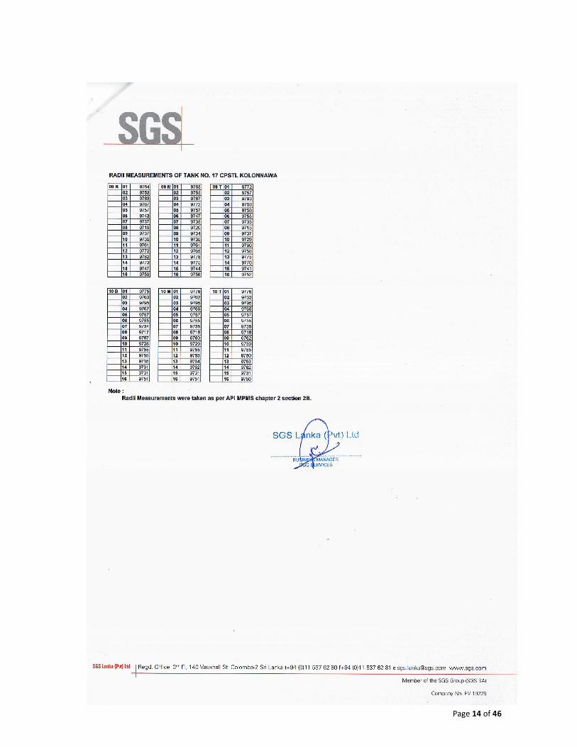
STANDARD 650 Standard shall be met. A Tank physical measurement report and tank
mechanical drawings will be provided to the bidder along with this document.
b. Upon the start of internal floating roof installation, or concurrent with assembly within a tank
under construction, the tank (interior shell and vertical components) shall be inspected by the
floating roof erector. The purpose of this inspection shall be to confirm plumbness of all
interior components, along with roundness and the condition of the shell (for the presence of
damage, projections, or obstructions) to verify that the floating roof and seals will operate
properly.
c. Any defects, projections, obstructions or tank tolerance limits (exceeding those defined in 7.5
of Appendix H of API 650), which would inhibit proper internal floating roof and seal operation,
that are identified by the internal floating roof erector shall be reported to the CPSTL
d. Deck seams and other joints that are required to be or vapor-tight per API STANDARD 650
H.4.1.3 shall be tested for leaks by the shop or field joint assembler. Joint testing shall be
performed by means of penetrating oil or another method consistent with those described in
this standard for testing cone-roof and/or tank-bottom seams, or by any other method mutually
agreed upon by the Purchaser and the roof Manufacturer.
e. The floating roof Manufacturer shall supply all floating roof closures required for testing per API
STANDARD 650 H.4.1.3, H.4.1.7, H.4.3.1, and H.6.2. Rivets, self-tapping screws, and
removable sections are not acceptable for test plugs.
f. Any flotation compartment that is completely shop-fabricated or assembled in such a manner
as to permit leak testing at the fabricating shop shall be leak tested at the shop as well as
retested in the field by the floating roof erector for all accessible seams. In the field assembly
yard or in the erected position, the erector shall spot leak test 10 % of the flotation
compartments, whether shop- or field-fabricated.
g. CPSTL representatives may select the specific compartments to test and the test location,
based on his visual inspections for indications of damage or potential. Any leaking
compartments shall be repaired and re-tested by the roof Manufacturer. If the testing finds any
leaks in compartments tested, except for those damaged by shipping, then 100 % of the roof
compartments shall be leak tested. Unless prohibited by safety concerns, leak testing shall be
at an internal pressure of 20 kPa to 55 kPa(3 lbf/in.2 to 8 lbf/in.2) gauge using a soap solution
or commercial leak detection solution.
h. Upon assembly and prior to a flotation test, the erector shall inspect to verify that the peripheral
seal produces an acceptable fit against the tank shell.
4.2.3.18 Initial Flotation
A flotation test and initial fill inspection shall be conducted by the CPSTL which shall be
witnessed by the supplier. CPSTL shall make water connections and supply all tank closures
required for testing and remove all water connections and temporary closures (including
gaskets, fasteners, test blanks, etc.) after completion of the test.

Page 9 of 46
Flotation test may be done using water or product at the option of the CPSTL. During this test,
the internal floating roof and all accessible compartments shall be jointly checked by supplier
and CPSTL to confirm that they are free from leaks. The appearance of a damp spot on the
upper side of the part in contact with the liquid shall be considered evidence of leakage.
During initial fill the internal floating roof shall be checked to confirm that it travels freely to its
full height. The peripheral seal shall be checked for proper operation throughout the entire
travel of the internal floating roof.
4.2.3.19 Commissioning of Internal Floating Roof
After initial floatation test the evaporation losses of the tank shall be monitored jointly for 14
days to confirm the satisfactory operation of Internal Floating Roof.

Page 10 of 46
PHYSICAL MEASUREMENT REPORT

Page 11 of 46

Page 12 of 46

Page 13 of 46
Page 14 of 46


Page 16 of 46

Page 17 of 46

Page 18 of 46

Page 19 of 46
DRAWINGS
� Drawing of Tank No 17
� Drawing of Tank No 22
� Drawing of Tank No 23

Page 20 of 46

Page 21 of 46

Page 22 of 46