3-d fea of hard turning: investigation of pcbn …3-d fea of hard turning: investigation of pcbn...
TRANSCRIPT
Transactions of NAMRI/SME 1 Volume 35, 2007
3-D FEA OF HARD TURNING: INVESTIGATION OF PCBN CUTTING TOOL MICRO- GEOMETRY EFFECTS
Yiğit Karpat and Tuğrul Özel Department of Industrial and Systems Engineering
Rutgers University Piscataway, New Jersey
KEYWORDS Finite Element Analysis, cutting tool micro-geometry, PCBN tools, and hard turning. ABSTRACT In this study, 3-D finite element modeling of precision hard turning has been used to investigate the effects of cutting edge micro-geometry on tool forces, temperatures and stresses in machining of AISI H13 steel using polycrystalline cubic boron nitrite (PCBN) inserts with two distinct edge preparations. Hard turning experiments were conducted to investigate the effects of cutting edge geometry, feed rate and cutting speed on tool flank wear and resultant forces. During hard turning experiments, low-grade PCBN inserts with honed and chamfered edge preparations and through-hardened AISI H-13 steel bars were used. Three components of tool forces and flank wear of the inserts were measured. PCBN inserts with honed micro-geometry cutting edge resulted in lower tool flank wear in all cutting conditions. The feasibility of using finite element analysis to investigate the cutting tool micro-geometry effects in 3D hard turning is also explored. INTRODUCTION Hard turning is a popular manufacturing process in producing finished components that are typically machined from alloy steels with hardness between 50 and 70 HRc (Koenig et al., 1984). Polycrystalline cubic boron nitrite (PCBN) cutting tools are widely used in hard turning. PCBN tools are designed with a certain micro-edge geometry with a process called edge preparation. Micro-geometry of a cutting edge plays a pivotal role on the workpiece surface properties and the performance of the cutting tool (Toenshoff et al. 1995). In order to improve
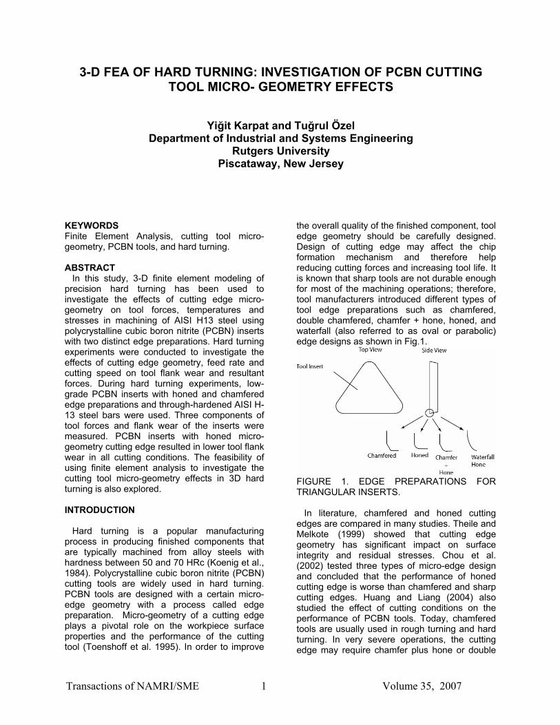
the overall quality of the finished component, tool edge geometry should be carefully designed. Design of cutting edge may affect the chip formation mechanism and therefore help reducing cutting forces and increasing tool life. It is known that sharp tools are not durable enough for most of the machining operations; therefore, tool manufacturers introduced different types of tool edge preparations such as chamfered, double chamfered, chamfer + hone, honed, and waterfall (also referred to as oval or parabolic) edge designs as shown in Fig.1.
FIGURE 1. EDGE PREPARATIONS FOR TRIANGULAR INSERTS. In literature, chamfered and honed cutting edges are compared in many studies. Theile and Melkote (1999) showed that cutting edge geometry has significant impact on surface integrity and residual stresses. Chou et al. (2002) tested three types of micro-edge design and concluded that the performance of honed cutting edge is worse than chamfered and sharp cutting edges. Huang and Liang (2004) also studied the effect of cutting conditions on the performance of PCBN tools. Today, chamfered tools are usually used in rough turning and hard turning. In very severe operations, the cutting edge may require chamfer plus hone or double
Transactions of NAMRI/SME 2 Volume 35, 2007
chamfer edge preparation in order to prevent chipping and breakage; honed tools are usually employed in finish hard turning. In recent years, finite element analysis (FEA) has become a major tool to calculate the process variables such as cutting forces, temperatures and stresses during machining. There are numerous studies on 2-D FEA of orthogonal cutting which provides essential information about the mechanics of cutting but the studies on 3-D turning are limited. A 3-D FEA of machining processes is needed to study practical machining operations. This will be very useful for process planners and tool designers to optimize cutting conditions and materials prior to actual production. The force, temperature and stress information provided by the FEA may be used to predict tool wear and according to this information existing cutting conditions may be altered, if necessary, in order to prolong tool life. The geometry of the cutting tool, workpiece and cutting tool material properties, and tool-chip friction conditions must be defined carefully to obtain reasonable results from finite element analysis. FEA was used to study the effects of edge geometry on the process variables. Shatla et al. (2000) used 2-D FEM modeling to study the influence of edge preparation (hone/chamfer) on process variables during orthogonal cutting of AISI H13 steel. Özel (2003) also used a 2-D FEM model to simulate orthogonal cutting of AISI H13 steel using honed and chamfered PCBN tools. Both models simulated the continuous chip formation and predicted forces, temperature and stress distributions. Chen et al., (2006) presented a 2-D model to study influence of edge geometry on tool wear rate and residual stress formation in PCBN machining of AISI H13 steel. Their model also simulated continuous chip formation. In 3-D FEA studies for modeling machining processes, Guo and Dornfeld (1998) presented a model to simulate burr formation when drilling stainless steel. Ceretti et al. (2000) used 3-D FEA to model in turning of aluminum alloys and low-carbon steels under orthogonal and oblique cutting conditions. Guo and Liu (2002) proposed 3-D FEA for hard turning of AISI 52100 steel using PCBN tools. The model was used to predict the cutting forces, temperature distribution over the cutting edge, and the residual stress distribution on the machined
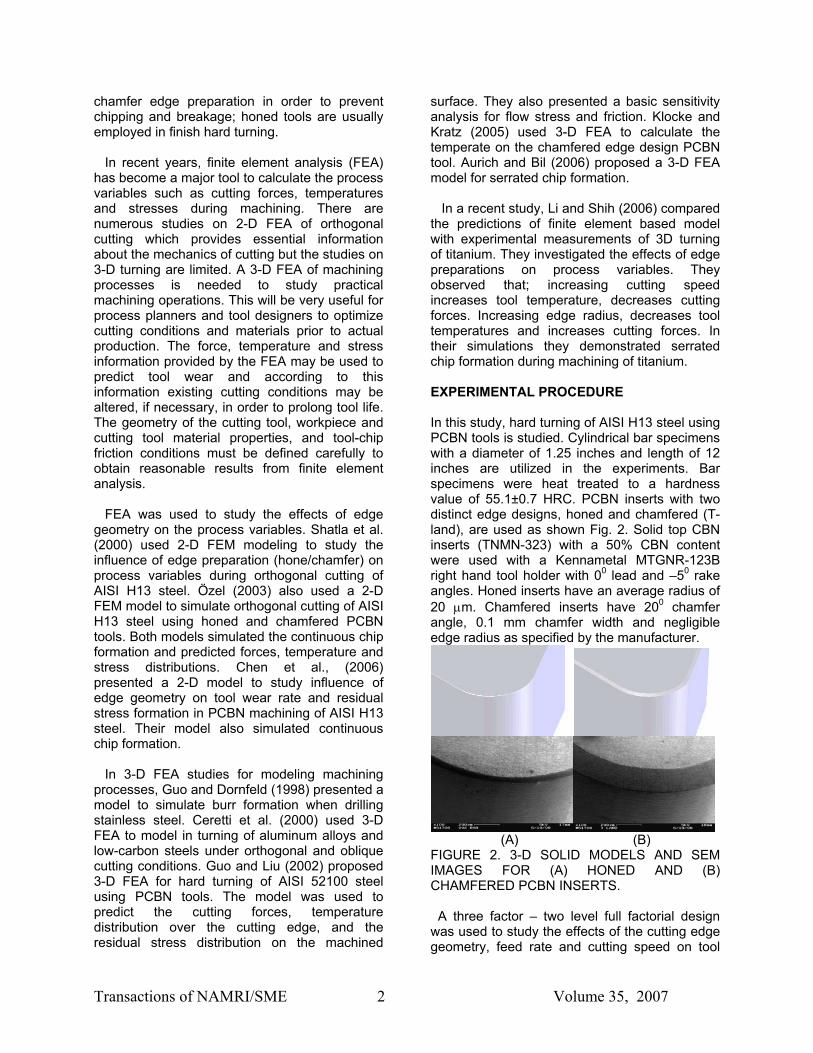
surface. They also presented a basic sensitivity analysis for flow stress and friction. Klocke and Kratz (2005) used 3-D FEA to calculate the temperate on the chamfered edge design PCBN tool. Aurich and Bil (2006) proposed a 3-D FEA model for serrated chip formation. In a recent study, Li and Shih (2006) compared the predictions of finite element based model with experimental measurements of 3D turning of titanium. They investigated the effects of edge preparations on process variables. They observed that; increasing cutting speed increases tool temperature, decreases cutting forces. Increasing edge radius, decreases tool temperatures and increases cutting forces. In their simulations they demonstrated serrated chip formation during machining of titanium. EXPERIMENTAL PROCEDURE In this study, hard turning of AISI H13 steel using PCBN tools is studied. Cylindrical bar specimens with a diameter of 1.25 inches and length of 12 inches are utilized in the experiments. Bar specimens were heat treated to a hardness value of 55.1±0.7 HRC. PCBN inserts with two distinct edge designs, honed and chamfered (T-land), are used as shown Fig. 2. Solid top CBN inserts (TNMN-323) with a 50% CBN content were used with a Kennametal MTGNR-123B right hand tool holder with 00 lead and –50 rake angles. Honed inserts have an average radius of 20 µm. Chamfered inserts have 200 chamfer angle, 0.1 mm chamfer width and negligible edge radius as specified by the manufacturer.
(A) (B) FIGURE 2. 3-D SOLID MODELS AND SEM IMAGES FOR (A) HONED AND (B) CHAMFERED PCBN INSERTS. A three factor – two level full factorial design was used to study the effects of the cutting edge geometry, feed rate and cutting speed on tool
Transactions of NAMRI/SME 3 Volume 35, 2007
wear at a constant depth of cut. The factors and factor levels are summarized in Table 1. Two replications of each factor level combinations were conducted.
TABLE 1. FACTORS AND FACTOR LEVELS Factor Factor levels Edge preparation Honed, Chamfered Feed rate 0.025, 0.05 (mm/rev) Cutting speed 150, 200 (m/min)
Longitudinal turning was conducted on a rigid, high-precision CNC lathe (Romi Centur 35E) at a constant depth of cut at 0.254 mm. The length of cut for each pass was about 225 mm in the axial feed direction. Due to availability constraints, each insert was used for one factor level combination, which consisted of 16 replications. In this manner each edge preparation was subject to the same number of tests and the same axial length of cut. Finally, tool wear measurements were conducted when a single pass is completed. PCBN inserts were examined using a tool-maker microscope to measure flank wear depth and detect undesirable features on the edge of the cutting tool. Cutting force measurements The cutting forces were measured with a three-component force dynamometer (Kistler Type 9121) mount on the turret disk of the CNC lathe via a custom designed turret adapter (Kistler type 9121) for the toolholder creating a very rigid tooling fixture. The charge signal generated at the dynamometer was amplified using charge amplifiers (Kistler Type 5814B1). The amplified signal is acquired and sampled by using data acquisition PCMCIA card and Matlab software on a laptop computer at a sampling frequency of 1000 Hz per channel. Three components of the resultant force are shown schematically in Fig. 3.
FIGURE 3. ILLUSTRATION OF BAR TURNING.
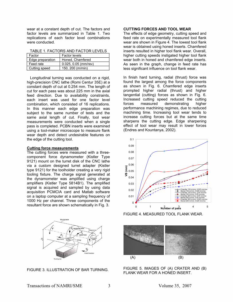
CUTTING FORCES AND TOOL WEAR The effects of edge geometry, cutting speed and feed rate on experimentally measured tool flank wear are shown in Figure 4. The lowest tool flank wear is obtained using honed inserts. Chamfered inserts resulted in higher tool flank wear. Overall, higher cutting speeds instigated higher tool flank wear both in honed and chamfered edge inserts. As seen in the graph, change in feed rate has less significant influence on tool flank wear. In finish hard turning, radial (thrust) force was found the largest among the force components as shown in Fig. 6. Chamfered edge inserts prompted higher radial (thrust) and higher tangential (cutting) forces as shown in Fig. 6. Increased cutting speed reduced the cutting forces measured demonstrating higher performance machining regimes, due to reduced machining time. Increasing tool wear tends to increase cutting forces but at the same time sharpens the cutting edge. Edge sharpening effect of tool wear may result in lower forces (Endres and Kountanya, 2002).
0
0.01
0.02
0.03
0.04
0.05
0.06
0.07
0.08
0.09
0.1
0 1 2 3 4 5Number of pass
VB (m
m)
Chamfer 150 m/min, 0.025 mm/revHoned 150 m/min, 0.025 mm/revChamfer 150 m/min, 0.05 mm/revHoned 150 m/min, 0.05 mm/revChamfer 200 m/min, 0.05 mm/revHoned 200 m/min, 0.05 mm/revChamfer 200 m/min, 0.025 mm/revHoned 200 m/min, 0.025 mm/rev
FIGURE 4. MEASURED TOOL FLANK WEAR.
(A) (B)
FIGURE 5. IMAGES OF (A) CRATER AND (B) FLANK WEAR FOR A HONED INSERT.

Transactions of NAMRI/SME 4 Volume 35, 2007
0
50
100
150
200
250
300
1 2 3 4 5
Number of pass
Fx (N
)Chamfer 150 m/min, 0.025 mm/rev
Honed 150 m/min, 0.025 mm/rev
Chamfer 150 m/min, 0.05 mm/rev
Honed 150 m/min, 0.05 mm/rev
Chamfer 200 m/min, 0.05 mm/rev
Honed 200 m/min, 0.05 mm/rev
Chamfer 200 m/min, 0.025 mm/rev
Honed 200 m/min, 0.025 mm/rev
A) RADIAL (THRUST) FORCE
0
10
20
30
40
50
60
70
80
90
100
1 2 3 4 5
Number of pass
Fy (N
)
Chamfer 150 m/min, 0.025 mm/rev
Honed 150 m/min, 0.025 mm/rev
Chamfer 150 m/min, 0.05 mm/rev
Honed 150 m/min, 0.05 mm/rev
Chamfer 200 m/min, 0.05 mm/rev
Honed 200 m/min, 0.05 mm/rev
Chamfer 200 m/min, 0.025 mm/rev
Honed 200 m/min, 0.025 mm/rev
B) FEED (AXIAL) FORCE
0
10
20
30
40
50
60
70
80
90
100
1 2 3 4 5
Number of pass
Fz (N
)
Chamfer 150 m/min, 0.025 mm/rev
Honed 150 m/min, 0.025 mm/rev
Chamfer 150 m/min, 0.05 mm/rev
Honed 150 m/min, 0.05 mm/rev
Chamfer 200 m/min, 0.05 mm/rev
Honed 200 m/min, 0.05 mm/rev
Chamfer 200 m/min, 0.025 mm/rev
Honed 200 m/min, 0.025 mm/rev
C) TANGENTIAL (CUTTING) FORCE FIGURE 6. MEASURED FORCES.
3-D FINITE ELEMENT ANALYSIS OF HARD TURNING A 3-D FEA model is developed using DEFORM-3D 5.0 finite element modeling software as shown in Fig. 7. The modeling approach is based on updated Lagrangian formulation for large plastic deformation analysis to simulate the chip formation. The chip separation from workpiece is achieved with continuous remeshing. The workpiece is model as plastic and PCBN tool is modeled as rigid.
FIGURE. 7 FINITE ELEMENT SIMULATION OF HARD TURNING WITH PCBN TOOL Two different workpiece material flow stress models for AISI H13 steel are used. The first model (Model-1) was the default AISI H13 steel model provided with the DEFORM-3D software as shown in Fig. 8, the second workpiece material model (Model-2) was the Johnson-Cook material model suggested by Chen et al. (2006). The parameters of the Johnson-Cook constitutive equation, given in Eq. (1), for AISI H13 steel are A= 715 MPa, B=329 MPa, C=0.03, n=0.28 and m=1.5.
( ) 0
0 0
1 ln 1m
n
m
T TA B CT T
εσ εε
− = + + − −
&
&
(1)
In Eq. (1) the parameter A is the initial yield strength of the material at room temperature. The equivalent plastic strain rate ε& is normalized with a reference strain rate 0ε& . T0 is room temperature, and Tm is the melting temperature of the material, and they are constants. While the parameter n takes into
Transactions of NAMRI/SME 5 Volume 35, 2007
account the strain hardening effect, the parameter m models the thermal softening effect and C represents strain rate sensitivity.
0
500
1000
1500
2000
2500
3000
3500
4000
4500
0 0.2 0.4 0.6 0.8 1 1.2
ε
σ, M
Pa
300 oC; 6000/s800 oC; 6000/s1200 oC; 6000/s300 oC; 10000/s800 oC; 10000/s1200 oC; 10000/s
FIGURE 8. FLOW STRESS FOR AISI H-13 STEEL IN MODEL-1. Thermal properties for AISI H-13 steel and PCBN material are given in Table 2. TABLE 2. THERMAL PROPERTIES Thermal conductivity, W/m-°K AISI H-13 steel PCBN
24.6 100
Heat capacity, J/g °K AISI H-13 steel PCBN
3.650 3.264
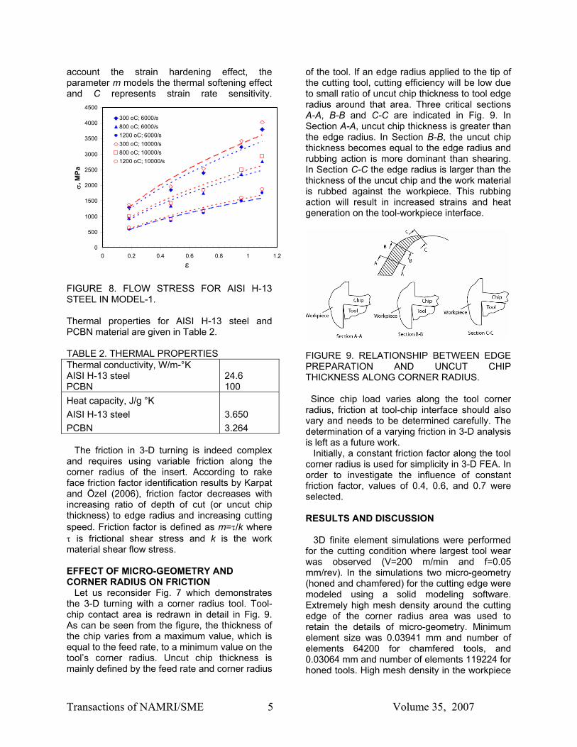
The friction in 3-D turning is indeed complex and requires using variable friction along the corner radius of the insert. According to rake face friction factor identification results by Karpat and Özel (2006), friction factor decreases with increasing ratio of depth of cut (or uncut chip thickness) to edge radius and increasing cutting speed. Friction factor is defined as m=τ/k where τ is frictional shear stress and k is the work material shear flow stress. EFFECT OF MICRO-GEOMETRY AND CORNER RADIUS ON FRICTION Let us reconsider Fig. 7 which demonstrates the 3-D turning with a corner radius tool. Tool-chip contact area is redrawn in detail in Fig. 9. As can be seen from the figure, the thickness of the chip varies from a maximum value, which is equal to the feed rate, to a minimum value on the tool’s corner radius. Uncut chip thickness is mainly defined by the feed rate and corner radius
of the tool. If an edge radius applied to the tip of the cutting tool, cutting efficiency will be low due to small ratio of uncut chip thickness to tool edge radius around that area. Three critical sections A-A, B-B and C-C are indicated in Fig. 9. In Section A-A, uncut chip thickness is greater than the edge radius. In Section B-B, the uncut chip thickness becomes equal to the edge radius and rubbing action is more dominant than shearing. In Section C-C the edge radius is larger than the thickness of the uncut chip and the work material is rubbed against the workpiece. This rubbing action will result in increased strains and heat generation on the tool-workpiece interface.
FIGURE 9. RELATIONSHIP BETWEEN EDGE PREPARATION AND UNCUT CHIP THICKNESS ALONG CORNER RADIUS.
Since chip load varies along the tool corner radius, friction at tool-chip interface should also vary and needs to be determined carefully. The determination of a varying friction in 3-D analysis is left as a future work. Initially, a constant friction factor along the tool corner radius is used for simplicity in 3-D FEA. In order to investigate the influence of constant friction factor, values of 0.4, 0.6, and 0.7 were selected. RESULTS AND DISCUSSION 3D finite element simulations were performed for the cutting condition where largest tool wear was observed (V=200 m/min and f=0.05 mm/rev). In the simulations two micro-geometry (honed and chamfered) for the cutting edge were modeled using a solid modeling software. Extremely high mesh density around the cutting edge of the corner radius area was used to retain the details of micro-geometry. Minimum element size was 0.03941 mm and number of elements 64200 for chamfered tools, and 0.03064 mm and number of elements 119224 for honed tools. High mesh density in the workpiece
Transactions of NAMRI/SME 6 Volume 35, 2007
was also used to capture the chip flow in a relatively small depth of cut. Predicted forces are presented in Table 3. In general axial and thrust force agree well with the experiments. However, cutting force is predicted much larger than the measured ones. TABLE 3. PREDICTED FORCES Edge Flow
Stress Model
Fric-tion factor
Axial Force (N)
Cutting Force (N)
Thrust Force (N)
Honed Model-1 0.4 22 119 90 Honed Model-1 0.6 25 115 89 Honed Model-2 0.4 20 115 65 Honed Model-2 0.7 41 160 129 Chamf. Model-2 0.4 37 145 147 Chamf. Model-2 0.7 45 145 193 Chamf. Model-1 0.7 38 122 165 Temperature field in the workpiece, chip and the tool were also calculated in 3-D FEA. A representative temperature field in workpiece and the chip is given in Fig. 10.
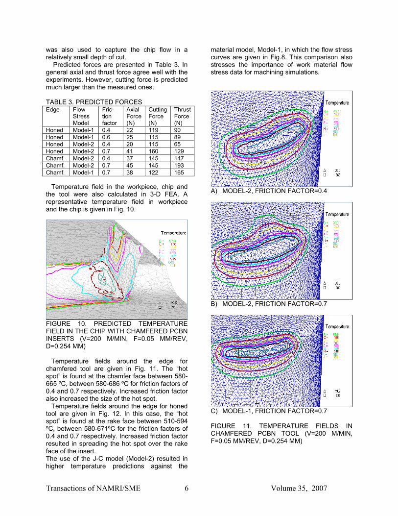
FIGURE 10. PREDICTED TEMPERATURE FIELD IN THE CHIP WITH CHAMFERED PCBN INSERTS (V=200 M/MIN, F=0.05 MM/REV, D=0.254 MM) Temperature fields around the edge for chamfered tool are given in Fig. 11. The “hot spot” is found at the chamfer face between 580-665 ºC, between 580-686 ºC for friction factors of 0.4 and 0.7 respectively. Increased friction factor also increased the size of the hot spot. Temperature fields around the edge for honed tool are given in Fig. 12. In this case, the “hot spot” is found at the rake face between 510-594 ºC, between 580-671ºC for the friction factors of 0.4 and 0.7 respectively. Increased friction factor resulted in spreading the hot spot over the rake face of the insert. The use of the J-C model (Model-2) resulted in higher temperature predictions against the
material model, Model-1, in which the flow stress curves are given in Fig.8. This comparison also stresses the importance of work material flow stress data for machining simulations.
A) MODEL-2, FRICTION FACTOR=0.4
B) MODEL-2, FRICTION FACTOR=0.7
C) MODEL-1, FRICTION FACTOR=0.7 FIGURE 11. TEMPERATURE FIELDS IN CHAMFERED PCBN TOOL (V=200 M/MIN, F=0.05 MM/REV, D=0.254 MM)

Transactions of NAMRI/SME 7 Volume 35, 2007
A) MODEL-1, FRICTION FACTOR=0.4
B) MODEL-1, FRICTION FACTOR=0.6
C) MODEL-2, FRICTION FACTOR=0.4
D) MODEL-2, FRICTION FACTOR=0.7 FIGURE 12. TEMPERATURE FIELDS IN HONED PCBN TOOL (V=200 M/MIN, F=0.05 MM/REV, D=0.254 MM) Effective stress distribution was also calculated through post-analysis where the cutting tool is
defined as elastic body. Resultant stress distribution is shown for chamfered tool in Fig. 13. Highest stress concentration was observed at the rake end of the chamfer face. The shape of the stress contour resembles the flank and crater wear images obtained experimentally. Furthermore, localized stress concentration is found to be greater in chamfered tool compared to honed tool as shown in Figures 13 and 14.
FIGURE 13. EFFECTIVE STRESS DISTRIBUTION ON CHAMFERED CBN TOOL (V=200 M/MIN, F=0.05 MM/REV, D=0.254 MM, FS MODEL-1, FRICTION FACTOR=0.7)
A) MODEL-1, FRICTION FACTOR=0.4
B) MODEL-1, FRICTION FACTOR=0.6 FIGURE 14. EFFECTIVE STRESS DISTRIBUTIONS ON HONED PCBN TOOL (V=200 M/MIN, F=0.05 MM/REV, D=0.254 MM)
Transactions of NAMRI/SME 8 Volume 35, 2007
CONCLUSIONS In this work, hard turning experiments were performed and the feasibility of using finite element analysis to investigate the cutting tool micro-geometry effects in 3-D hard turning is explored. From the experimental and simulation results, the following conclusions can be drawn:
• Hone micro-geometry inserts have tendency to result in lower forces, hence lower flank wear.
• Chamfer micro-geometry provides higher localized stress concentration.
• As commonly known, FEA simulations are sensitive to the work material model and the friction factor.
• Larger friction factor results in higher tool temperatures.
• Explanation of crater wear location can be made with the aid of predicted temperature and stress fields.
• For more accurate predictions, variable friction models along the corner radius are worth being explored with 3-D FEA.
• Variable micro-geometry edge design along the corner radius to maintain a constant chip load to edge radius ratio may affect temperatures and stresses applied to the tool.
REFERENCES Aurich, J.C., and H. Bil, (2006), “3D finite element modelling of segmented chip formation,” Annals of the CIRP, Vol. 55/1, pp. 47-50. Ceretti, E., C. Lazzaroni, L. Menegardo, and T. Altan, (2000), “Turning simulations using a three-dimentional FEM code,”, Journal of Materials Processing Technology, Vol. 98, pp. 99-103. Chen L., T.I. El-Wardany, M. Nasr, M.A. Elbestawi, (2006), “Effects of edge preparation and feed when hard turning a hot work die steel with polycrystalline cubic boron nitride tools,” Annals of the CIRP, Vol. 55/1, pp. 89-92. Chou Y.K., C.J. Evans, and M.M. Barash, (2002), “Experimental investigation on CBN turning of hardened AISI 52100 steel,” Journal of Materials Processing Technology, Vol. 124, pp. 274-283. Endres, W.J., and R. Kountanya, (2002), “The effects of corner radius and edge radius on tool flank wear,” Transactions of North American Manufacturing Research Institute, Vol. XXX pp. 401-407.
Guo, Y., and D.A. Dornfeld, (1998), “Finite element analysis of drilling burr minimization with a backup material,” Transactions of North American Manufacturing Research Institute, Vol. XXVI, pp. 207-212. Guo, Y., and C.R. Liu, (2002) “ 3D FEA modeling of hard turning,” ASME Journal of Manufacturing Science and Engineering, Vol. 124, pp. 189-199. Huang, Y., and S.Y. Liang, (2004), “Effect of cutting conditions on tool performance in CBN hard turning,” Transactions of North American Manufacturing Research Institute, Vol. XXXII, pp. 511-518. Karpat, Y., and T. Özel, (2006), "Identification of Friction Factors for Chamfered and Honed Tools Through Slip-line field Analysis," Proceedings of 2006 ASME International Conference on Manufacturing Science and Engineering, Paper No. 21127, Ypsilanti, MI. Koenig W.A, R. Komanduri, H.K. Toenshoff, and G. Ackeshott, (1984), “Machining of hard metals,” Annals of the CIRP, Vol.33/2, pp. 417-427. Klocke, F., H. Kartz, (2005), “Advanced Tool Edge Geometry for High Precision Hard Turning,” Annals of the CIRP, Vol. 54/1, pp. 47-50. Li R. and A. Shih, (2006), “Finite element modeling of 3D turning of titanium,” International Journal of Advanced Manufacturing Technology, Vol. 29, No 3-4, pp. 253-261. Özel, T., (2003), "Modeling of Hard Part Machining: Effect of Insert Edge Preparation for CBN Cutting Tools," Journal of Materials Processing Technology, Vol.141, pp. 284-293. Thiele J.D., and S.N. Melkote, (1999), “The effect of tool edge geometry on workpiece subsurface deformation and through thickness residual stresses for hard turning of AISI 52100 steel,” Transactions of North American Manufacturing Research Institute, Vol. XXVII, pp. 135-140. Toenshoff, H., H-G., Wobeker, and D., Brandt, (1995), “Hard turning – influences on the workpiece properties,” Transactions of North American Manufacturing Research Institute, Vol. XXIII, pp. 215-220. Shatla, M., Y-C. Yen, and T. Altan, (2000), “Tool-workpiece interface in orthogonal cutting application of FEM modeling,” Transactions of North American Manufacturing Research Institute, Vo. XXVIII, pp. 173-178.