pcd - pcbn tools
TRANSCRIPT
PRODUCTION TOOLING
YOUR IDEAL PARTNER
PRO
DU
CTIO
N T
OO
LIN
G
MC s.a.sVia Viadagola, 15I-40057 Granarolo dell’Emilia (BO)Tel. + 39 051 6056626Fax + 39 051 [email protected]
PRODUCTION TOOLING
PCD - PCBN TOOLS
22
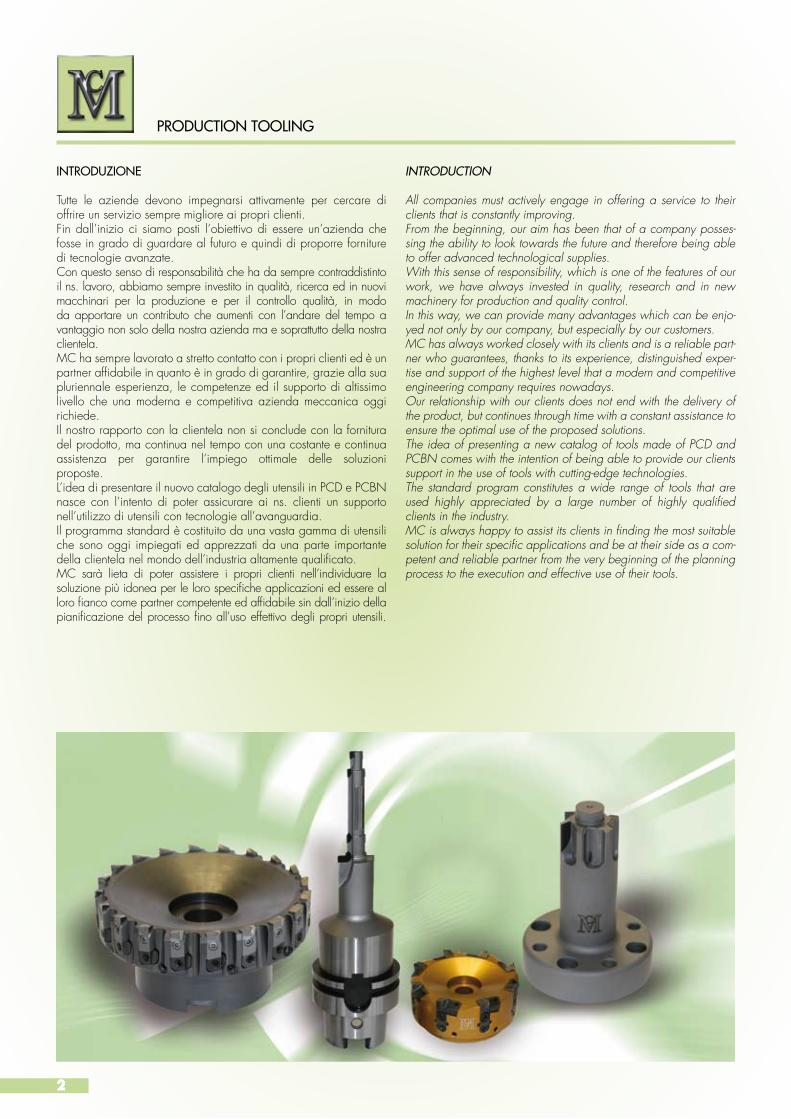
All companies must actively engage in offering a service to their clients that is constantly improving.From the beginning, our aim has been that of a company posses-sing the ability to look towards the future and therefore being able to offer advanced technological supplies. With this sense of responsibility, which is one of the features of our work, we have always invested in quality, research and in new machinery for production and quality control. In this way, we can provide many advantages which can be enjo-yed not only by our company, but especially by our customers. MC has always worked closely with its clients and is a reliable part-ner who guarantees, thanks to its experience, distinguished exper-tise and support of the highest level that a modern and competitive engineering company requires nowadays.Our relationship with our clients does not end with the delivery of the product, but continues through time with a constant assistance to ensure the optimal use of the proposed solutions. The idea of presenting a new catalog of tools made of PCD and PCBN comes with the intention of being able to provide our clients support in the use of tools with cutting-edge technologies. The standard program constitutes a wide range of tools that are used highly appreciated by a large number of highly qualified clients in the industry.MC is always happy to assist its clients in finding the most suitable solution for their specific applications and be at their side as a com-petent and reliable partner from the very beginning of the planning process to the execution and effective use of their tools.
Tutte le aziende devono impegnarsi attivamente per cercare di offrire un servizio sempre migliore ai propri clienti. Fin dall’inizio ci siamo posti l’obiettivo di essere un’azienda che fosse in grado di guardare al futuro e quindi di proporre forniture di tecnologie avanzate. Con questo senso di responsabilità che ha da sempre contraddistinto il ns. lavoro, abbiamo sempre investito in qualità, ricerca ed in nuovi macchinari per la produzione e per il controllo qualità, in modo da apportare un contributo che aumenti con l’andare del tempo a vantaggio non solo della nostra azienda ma e soprattutto della nostra clientela.MC ha sempre lavorato a stretto contatto con i propri clienti ed è un partner affidabile in quanto è in grado di garantire, grazie alla sua pluriennale esperienza, le competenze ed il supporto di altissimo livello che una moderna e competitiva azienda meccanica oggi richiede. Il nostro rapporto con la clientela non si conclude con la fornitura del prodotto, ma continua nel tempo con una costante e continua assistenza per garantire l’impiego ottimale delle soluzioni proposte. L’idea di presentare il nuovo catalogo degli utensili in PCD e PCBN nasce con l’intento di poter assicurare ai ns. clienti un supporto nell’utilizzo di utensili con tecnologie all’avanguardia.Il programma standard è costituito da una vasta gamma di utensili che sono oggi impiegati ed apprezzati da una parte importante della clientela nel mondo dell’industria altamente qualificato.MC sarà lieta di poter assistere i propri clienti nell’individuare la soluzione più idonea per le loro specifiche applicazioni ed essere al loro fianco come partner competente ed affidabile sin dall’inizio della pianificazione del processo fino all’uso effettivo degli propri utensili.
INTRODUCTION
PRODUCTION TOOLING
INTRODUZIONE

3
INDICE / INDEX
PCD – PCBN Applicazioni / PCD - PCBN Applications Pagina / page 4
Frese saldo-brasate in PCD / PCD brazed milling cutters Pagina / page 6Programma standard / Standard program Pagina / page 8 BMD 4020 BMD 4030 BMD 6030 BMD 4010 BMD 4060 BMD 4050-52 - BMD 6050-52 - BMD 5050-52 - BMD 8050-52Guida alle formule / General acronims and formula Pagina / page 17Note tecniche / Technical hints Pagina / page 18Esempi di lavorazione / Application examples Pagina / page 20 Frese JET FEED - Frese HPC / JET FEED mills - HPC mills Pagina / page 21Fresatura in piano con inserti in PCD / Flat milling cutters with PCD inserts Pagina / page 24Finitura ad alta velocità della ghisa / High - speed finish of cast iron Pagina / page 28Programma standard / Standard program Pagina / page 30IMD 4040-41 IMD 6040-41 IMD 5040-41 IMD 3040-41 IMD 8040-41 Pagina / page 8Inserti intercambiabili / Indexable inserts Pagina / page 40Chiave di lettura dei codici degli inserti / Inserts designation Pagina / page 41Impiego delle qualità per gli inserti / Inserts grade application Pagina / page 44Note tecniche per frese / Technical hints for milling cutters Pagina / page 45Indicazioni per la lavorazione / Machining instructions Pagina / page 46Guida alle formule / General formula list Pagina / page 47Schema di montaggio per frese /Handling milling cutters Pagina / page 48Ricambi / Spare parts Pagina / page 50Esempi di lavorazione / Application examples Pagina / page 52Frese a spianare con cartucce registrabili e inserti in PCD / Milling cutters with indexable cartridges and PCD inserts Pagina / page 61Programma standard / Standard program Pagina / page 62IMD 5030 IMD 5035 IMD 8030-32Taglienti in PCD / PCD cutting edges Pagina / page 65Note tecniche per frese / Technical hints for milling cutters Pagina / page 66Guida alle formule / General acronims and formulas Pagina / page 67Schema di montaggio per frese / Handling milling cutters Pagina / page 68Ricambi / Spare parts Pagina / page 74
Mandrini per frese / Holders for milling cutters Pagina / page 76
Utensili in PCD / PCD tools Pagina / page 86Programma standard alesatori BRD 4060-62 / Reamers standard program BRD 4060-62 Pagina / page 88Chiave di lettura dei codici degli alesatori / Reamers designation Pagina / page 90Geometria di taglio / Cutting geometry Pagina / page 91Programma standard alesatori BRD 6060-62 / Reamers standard program BRD 6060-62 Pagina / page 92Chiave di lettura dei codici degli alesatori / Reamers designation Pagina / page 94Geometria di taglio / Cutting geometryNote tecniche per alesatori / Technical hints for reamers Pagina / page 95
Adattatori / Adapters Pagina / page 96
Assistenza / Assistence Pagina / page 104
Competenza / Competence Pagina / page 105
La competenza negli utensili / Tools competence Pagina / page 106
PRODUCTION TOOLING
4
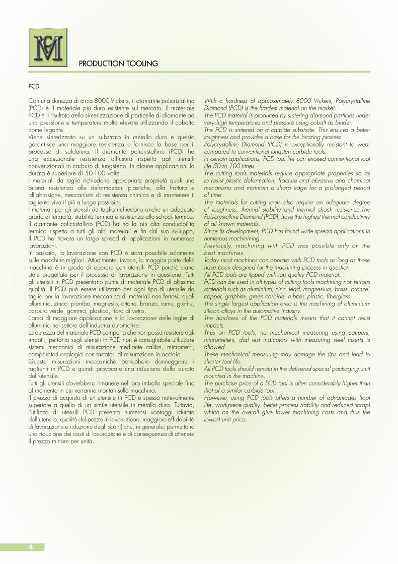
Con una durezza di circa 8000 Vickers, il diamante policristallino (PCD) è il materiale più duro esistente sul mercato. Il materiale PCD è il risultato della sinterizzazione di particelle di diamante ad una pressione e temperature molto elevate utilizzando il cobalto come legante. Viene sinterizzato su un substrato in metallo duro e questo garantisce una maggiore resistenza e fornisce la base per il processo di saldatura. Il diamante policristallino (PCD) ha una eccezionale resistenza all’usura rispetto agli utensili convenzionali in carburo di tungsteno. In alcune applicazioni la durata è superiore di 50-100 volte .I materiali da taglio richiedono appropriate proprietà quali una buona resistenza alle deformazioni plastiche, alla frattura e all’abrasione, meccanismi di resistenza chimica e di mantenere il tagliente vivo il più a lungo possibile. I materiali per gli utensili da taglio richiedono anche un adeguato grado di tenacità, stabilità termica e resistenza allo schock termico. Il diamante policristallino (PCD) ha ha la più alta conducibilità termica rispetto a tutti gli altri materiali e fin dal suo sviluppo, il PCD ha trovato un largo spread di applicazioni in numerose lavorazioni. In passato, la lavorazione con PCD è stata possibile solamente sulle macchine migliori. Attualmente, invece, la maggior parte delle macchine è in grado di operare con utensili PCD purchè siano state progettate per il processo di lavorazione in questione. Tutti gli utensili in PCD presentano punte di materiale PCD di altissima qualità. Il PCD può essere utilizzato per ogni tipo di utensile da taglio per la lavorazione meccanica di materiali non ferrosi, quali alluminio, zinco, piombo, magnesio, ottone, bronzo, rame, grafite, carburo verde, gomma, plastica, fibra di vetro.L’area di maggiore applicazione è la lavorazione delle leghe di alluminio nel settore dell’industria automotive.La durezza del materiale PCD comporta che non possa resistere agli impatti, pertanto sugli utensili in PCD non è consigliabile utilizzare sistemi meccanici di misurazione mediante calibri, micrometri, comparatori analogici con tastatori di misurazione in acciaio. Queste misurazioni meccaniche potrebbero danneggiare i taglienti in PCD e quindi provocare una riduzione della durata dell’utensile. Tutti gli utensili dovrebbero rimanere nel loro imballo speciale fino al momento in cui verranno montati sulla macchina.Il prezzo di acquisto di un utensile in PCD è spesso notevolmente superiore a quello di un simile utensile in metallo duro. Tuttavia, l’utilizzo di utensili PCD presenta numerosi vantaggi (durata dell’utensile, qualità del pezzo in lavorazione, maggiore affidabilità di lavorazione e riduzione degli scarti) che, in generale, permettono una riduzione dei costi di lavorazione e di conseguenza di ottenere il prezzo minore per unità.
With a hardness of approximately 8000 Vickers, Polycrystalline Diamond (PCD) is the hardest material on the market. The PCD material is produced by sintering diamond particles under very high temperatures and pressure using cobalt as binder.The PCD is sintered on a carbide substrate. This ensures a better toughness and provides a base for the brazing process.Polycrystalline Diamond (PCD) is exceptionally resistant to wear compared to conventional tungsten carbide tools. In certain applications, PCD tool life can exceed conventional tool life 50 to 100 times.The cutting tools materials require appropriate properties so as to resist plastic deformation, fracture and abrasive and chemical mecanisms and maintain a sharp edge for a prolonged period of time.The materials for cutting tools also require an adeguate degree of toughness, thermal stability and thermal shock resistance.The Polycrystalline Diamond (PCD), have the highest thermal conductivity of all known materials. Since its development, PCD has found wide spread applications in numerous machinining. Previously, machining with PCD was possible only on the best machines.Today most machines can operate with PCD tools as long as these have been designed for the machining process in question.All PCD tools are tipped with top quality PCD material.PCD can be used in all types of cutting tools machining non-ferrous materials such as aluminium, zinc, lead, magnesium, brass, bronze, copper, graphite, green carbide, rubber, plastic, fiberglass. The single largest application area is the machining of aluminium-silicon alloys in the automotive industry.The hardness of the PCD materials means that it cannot resist impacts.Thus on PCD tools, no mechanical measuring using calipers, micrometers, dial test indicators with measuring steel inserts is allowed. These mechanical measuring may damage the tips and lead to shorter tool life. All PCD tools should remain in the delivered special packaging until mounted in the machine.The purchase price of a PCD tool is often considerably higher than that of a similar carbide tool. However, using PCD tools offers a number of advantages (tool life, workpiece quality, better process riability and reduced scrap) which on the overall give lower machining costs and thus the lowest unit price.
PCD
PRODUCTION TOOLING

5
Il policristallino di nitruro di boro cubico (PCBN), viene prodotto dalla sinterizzazione di particelle di CBN (nitruro di boro cubico) con particelle varie di ceramica ad una pressione e temperature molto elevate e viene sinterizzato su un substrato in metallo duro.I cristalli di CBN sono orientati in modo casuale e garantiscono caratteristiche di durezza e resistenza all’usura eccezionali.Il CBN è il secondo materiale più duro esistente sul mercato dopo il PCD e possiede elevate proprietà di resistenza termica e chimica.Fin dal suo sviluppo oltre 60 anni fa, gli utensili in PCBN vengono usati per la lavorazione di acciai duri, consentendo una effettiva riduzione di costi rispetto alla operazione convenzionale di rettifica.Le principali aree di applicazione per gli utensili da taglio in PCBN sono la lavorazione di sgrossatura e finitura degli acciai con durezza superiore ai 45 HRC, delle ghise grigie e delle ghise sferoidali, sia per operazioni di barenatura, che di tornitura e fresatura.L’impiego di utensili in CBN consente importanti vantaggi economici in termini di produttività e riduzione dei costi, in alternativa agli utensili convenzionali in carburo di tunghsteno.
Polycristalline cubic boron nitride (PCBN) composites are produced by sintering micron CBN (cubic boron nitride) powered with various ceramics particles, so as to produce extremely hard and thermally stable tooling materials.Most PCBN materials are integrally bonded to a cemented carbide substrate. The CBN crystals are randomly oriented and ensure exceptional hardness and wear resistance. CBN is the second hardest material known after syntetic diamond, but has high thermal and chemical resistence properties.Since their development over a quarter of century ago, tools are used for the machining of hardned steel, offering viable more cost effective alternative to conventional grinding process. The principal application areas for PCBN cutting tools are rough-and finish-machining of steel greater 45 HRC, grey cast irons and hard cast irons as well as fine boring, turning and milling operations.Using CBN tools provides important economic benefits in terms of productivity, reducing costs as an alternative to the conventional tools tunghsteno carbide.
PCBN
PRODUCTION TOOLING
PCD PCBN

66
FRESE SALDOBRASATE IN PCDPCD BRAZED MILLING CUTTERS
FRESE SALDOBRASATE IN PCDPCD BRAZED MILLING CUTTERS

7
La combinazione tra l’elevata durezza del diamante policristallino sintetico e la tenacità del metallo duro che costituisce il substrato su cui viene sinterizzato il PCD, rappresentano la migliore scelta per l’operazione di fresatura delle leghe leggere.E’ con la lavorazione di fresatura che si evidenziano tutti i vantaggi del PCD.Questi utensili vengono impiegati per la lavorazione ad alta velocità.La eccezionale accuratezza nella lavorazione dei taglienti in PCD, in aggiunta alla loro elevata resistenza ed alla stabilità del corpo utensile garantiscono economicità alla vita utensile.Ciò consente di poter ridurre i tempi di lavorazione e quindi i costi del processo.Oltre al programma standard, che prevede per tutte le frese la lubrificazione centrale, produciamo molte altre tipologie di frese saldobrasate concepite per applicazioni speciali.
Programma standard
• Frese a codolo cilindrico
• Frese a codolo filettato
• Frese a spianare con attacco a manicotto secondo ISO 6442
• Frese a spianare con attacco HSK -A secondo ISO 12641-1
Standard program
•Milling cutters with cilindrical shaft
•Screw-on type end mill
•Face milling cutter according to ISO 6442
•Face milling cutter HSK-A shaft according to ISO 12614-1
The combination between the hardness of a synthetic polycrystalline diamond and the toughness of the hard metal that constitutes the substrate, on which the PCD is sintered, represents the best choice for the process of milling light alloys. The advantages of PCD are visible during the milling process. These tools are used for high-speed machining. The exceptional accuracy in the manufacturing of PCD cutting edges, in addition to their high resistance and stability of the body, guarantee an economical and long lasting tool.This allows to not only reduce the manufacturing time, but also the production cost. In addition to the standard program, which provides all milling cutters with a central coolant supply directly to the cutting edges, we produce many other types of milling brazed cutters designed for special applications.
FRESE SALDOBRASATE IN PCD PCD BRAZED MILLING CUTTERS
PRODUCTION TOOLING
8
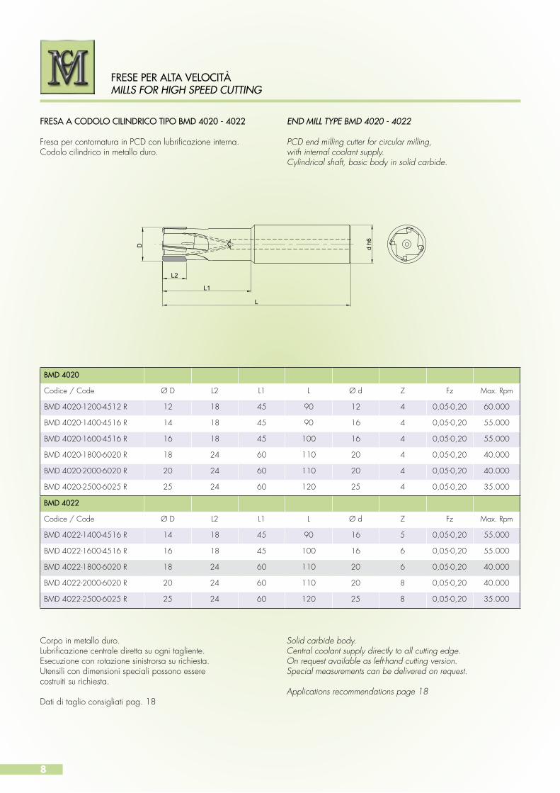
BMD 4020
Codice / Code Ø D L2 L1 L Ø d Z Fz Max. Rpm
BMD 4020-1200-4512 R 12 18 45 90 12 4 0,05-0,20 60.000
BMD 4020-1400-4516 R 14 18 45 90 16 4 0,05-0,20 55.000
BMD 4020-1600-4516 R 16 18 45 100 16 4 0,05-0,20 55.000
BMD 4020-1800-6020 R 18 24 60 110 20 4 0,05-0,20 40.000
BMD 4020-2000-6020 R 20 24 60 110 20 4 0,05-0,20 40.000
BMD 4020-2500-6025 R 25 24 60 120 25 4 0,05-0,20 35.000
BMD 4022
Codice / Code Ø D L2 L1 L Ø d Z Fz Max. Rpm
BMD 4022-1400-4516 R 14 18 45 90 16 5 0,05-0,20 55.000
BMD 4022-1600-4516 R 16 18 45 100 16 6 0,05-0,20 55.000
BMD 4022-1800-6020 R 18 24 60 110 20 6 0,05-0,20 40.000
BMD 4022-2000-6020 R 20 24 60 110 20 8 0,05-0,20 40.000
BMD 4022-2500-6025 R 25 24 60 120 25 8 0,05-0,20 35.000
FRESA A CODOLO CILINDRICO TIPO BMD 4020 - 4022
Fresa per contornatura in PCD con lubrificazione interna.Codolo cilindrico in metallo duro.
Corpo in metallo duro.Lubrificazione centrale diretta su ogni tagliente.Esecuzione con rotazione sinistrorsa su richiesta.Utensili con dimensioni speciali possono esserecostruiti su richiesta.
Dati di taglio consigliati pag. 18
Solid carbide body.Central coolant supply directly to all cutting edge.On request available as left-hand cutting version.Special measurements can be delivered on request.
Applications recommendations page 18
END MILL TYPE BMD 4020 - 4022
PCD end milling cutter for circular milling,with internal coolant supply.Cylindrical shaft, basic body in solid carbide.
D d h6
L
L1
L2
FRESE PER ALTA VELOCITÀMILLS FOR HIGH SPEED CUTTING

9
BMD 4030
Codice / Code Ø D L2 L1 L Ø d Z X Fz Max. Rpm
BMD 4030-0600-1506 R 6 10 15 60 6 2 0,1x45° 0,05-0,20 60.000
BMD 4030-0600-2506 R 6 18 25 80 6 2 0,1x45° 0,05-0,20 60.000
BMD 4030-0800-2008 R 8 10 20 80 8 2 0,1x45° 0,05-0,20 60.000
BMD 4030-0800-3008 R 8 18 30 90 8 2 0,1x45° 0,05-0,20 60.000
BMD 4030-1000-2010 R 10 10 20 80 10 2 0,1x45° 0,05-0,20 60.000
BMD 4030-1000-3010 R 10 18 30 90 10 2 0,1x45° 0,05-0,20 60.000
BMD 4030-1200-3012 R 12 10 30 100 12 2 0,1x45° 0,05-0,20 60.000
BMD 4030-1200-3512 R 12 18 35 105 12 2 0,1x45° 0,05-0,20 60.000
FRESA A CODOLO CILINDRICO TIPO BMD 4030
Fresa forante in PCD con lubrificazione interna,nr. 1 taglientre oltre il centro.Codolo cilindrico in metallo duro.
Corpo in metallo duro.Lubrificazione centrale diretta su ogni tagliente.Esecuzione con rotazione sinistrorsa su richiesta.Utensili con dimensioni speciali possono esserecostruiti su richiesta.
Dati di taglio consigliati pag. 18
Solid carbide body.Central coolant supply directly to all cutting edge.On request available as left-hand cutting version.Special measurements can be delivered on request.
Applications recommendations page 18
END MILL TYPE BMD 4030
PCD slot milling cutter with nr.1 cutting edge over centre.Internal coolant supply. Cylindrical shaft, basic body in solid carbide.
L
D d h6
X L2
L1
FRESE PER ALTA VELOCITÀMILLS FOR HIGH SPEED CUTTING
10
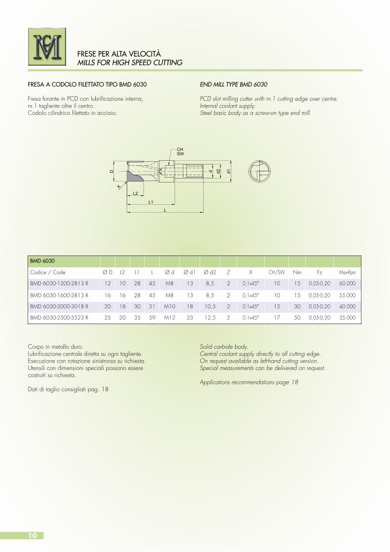
BMD 6030
Codice / Code Ø D L2 L1 L Ø d Ø d1 Ø d2 Z X CH/SW Nm Fz Max-Rpm
BMD 6030-1200-2813 R 12 10 28 45 M8 13 8,5 2 0,1x45° 10 15 0,05-0,20 60.000
BMD 6030-1600-2813 R 16 16 28 45 M8 13 8,5 2 0,1x45° 10 15 0,05-0,20 55.000
BMD 6030-2000-3018 R 20 18 30 51 M10 18 10,5 2 0,1x45° 15 30 0,05-0,20 40.000
BMD 6030-2500-3523 R 25 20 35 59 M12 23 12,5 2 0,1x45° 17 50 0,05-0,20 35.000
FRESA A CODOLO FILETTATO TIPO BMD 6030
Fresa forante in PCD con lubrificazione interna,nr.1 tagliente oltre il centro.Codolo cilindrico filettato in acciaio.
END MILL TYPE BMD 6030
PCD slot milling cutter with nr.1 cutting edge over centre.Internal coolant supply.Steel basic body as a screw-on type end mill.
CHSW
D
L2
L1
d2d d1
L
X
Corpo in metallo duro.Lubrificazione centrale diretta su ogni tagliente.Esecuzione con rotazione sinistrorsa su richiesta.Utensili con dimensioni speciali possono esserecostruiti su richiesta.
Dati di taglio consigliati pag. 18
Solid carbide body.Central coolant supply directly to all cutting edge.On request available as left-hand cutting version.Special measurements can be delivered on request.
Applications recommendations page 18
FRESE PER ALTA VELOCITÀMILLS FOR HIGH SPEED CUTTING

FRESA SFERICA TIPO BMD 4010
Fresa sferica in PCD con lubrificazione interna.Codolo cilindrico in metallo duro.
BALL END MILL TYPE BMD 4010
PCD milling cutter with spherical head.Internal coolant supply.Cylindrical shaft, basic body in solid carbide.
D d h6
L1
L2
L
BMD 4010
Codice / Code Ø D L2 L1 L Ø d Z Fz Max. Rpm
BMD 4010-0600-3006 R 6 6 30 80 6 2 0,05-0,20 60.000
BMD 4010-0600-4006 R 6 6 40 100 6 2 0,05-0,20 60.000
BMD 4010-0800-3008 R 8 8 30 80 8 2 0,05-0,20 60.000
BMD 4010-0800-4008 R 8 8 40 100 8 2 0,05-0,20 60.000
BMD 4010-1000-3010 R 10 10 30 80 10 2 0,05-0,20 60.000
BMD 4010-1000-4010 R 10 10 40 100 10 2 0,05-0,20 60.000
BMD 4010-1200-3012 R 12 12 30 100 12 2 0,05-0,20 60.000
BMD 4010-1200-4012 R 12 12 40 120 12 2 0,05-0,20 60.000
Corpo in metallo duro.Lubrificazione centrale diretta su ogni tagliente.Esecuzione con rotazione sinistrorsa su richiesta.Utensili con dimensioni speciali possono esserecostruiti su richiesta.
Dati di taglio consigliati pag. 18
Solid carbide body.Central coolant supply directly to all cutting edge.On request available as left-hand cutting version.Special measurements can be delivered on request.
Applications recommendations page 18
FRESE PER ALTA VELOCITÀMILLS FOR HIGH SPEED CUTTING
11
12
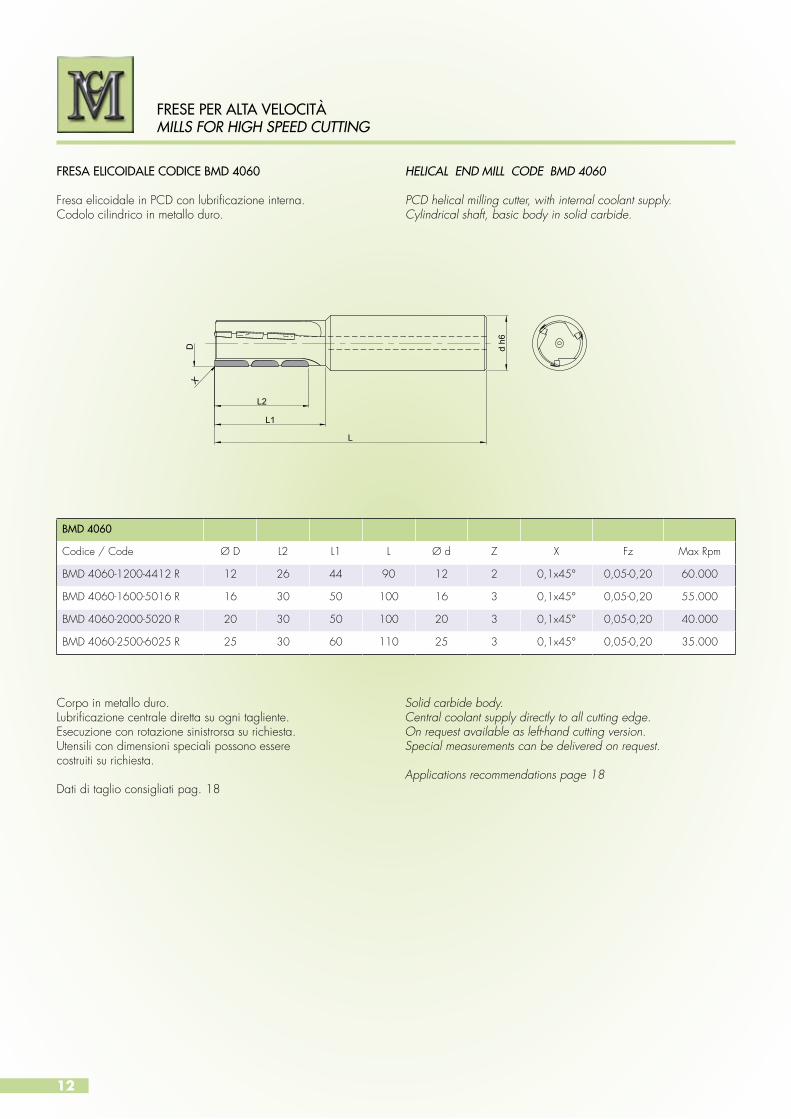
FRESA ELICOIDALE CODICE BMD 4060 Fresa elicoidale in PCD con lubrificazione interna.Codolo cilindrico in metallo duro.
HELICAL END MILL CODE BMD 4060
PCD helical milling cutter, with internal coolant supply.Cylindrical shaft, basic body in solid carbide.
L
L1
L2
D d h6
X
Corpo in metallo duro.Lubrificazione centrale diretta su ogni tagliente.Esecuzione con rotazione sinistrorsa su richiesta.Utensili con dimensioni speciali possono esserecostruiti su richiesta.
Dati di taglio consigliati pag. 18
Solid carbide body.Central coolant supply directly to all cutting edge.On request available as left-hand cutting version.Special measurements can be delivered on request.
Applications recommendations page 18
BMD 4060
Codice / Code Ø D L2 L1 L Ø d Z X Fz Max Rpm
BMD 4060-1200-4412 R 12 26 44 90 12 2 0,1x45° 0,05-0,20 60.000
BMD 4060-1600-5016 R 16 30 50 100 16 3 0,1x45° 0,05-0,20 55.000
BMD 4060-2000-5020 R 20 30 50 100 20 3 0,1x45° 0,05-0,20 40.000
BMD 4060-2500-6025 R 25 30 60 110 25 3 0,1x45° 0,05-0,20 35.000
FRESE PER ALTA VELOCITÀMILLS FOR HIGH SPEED CUTTING
13
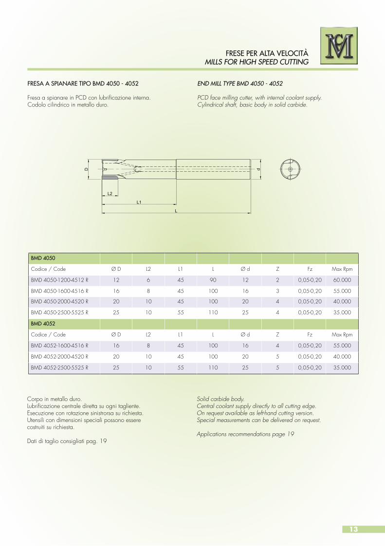
END MILL TYPE BMD 4050 - 4052
PCD face milling cutter, with internal coolant supply.Cylindrical shaft, basic body in solid carbide.
L
L1
L2
D d
Corpo in metallo duro.Lubrificazione centrale diretta su ogni tagliente.Esecuzione con rotazione sinistrorsa su richiesta.Utensili con dimensioni speciali possono esserecostruiti su richiesta.
Dati di taglio consigliati pag. 19
Solid carbide body.Central coolant supply directly to all cutting edge.On request available as left-hand cutting version.Special measurements can be delivered on request.
Applications recommendations page 19
BMD 4050
Codice / Code Ø D L2 L1 L Ø d Z Fz Max Rpm
BMD 4050-1200-4512 R 12 6 45 90 12 2 0,05-0,20 60.000
BMD 4050-1600-4516 R 16 8 45 100 16 3 0,05-0,20 55.000
BMD 4050-2000-4520 R 20 10 45 100 20 4 0,05-0,20 40.000
BMD 4050-2500-5525 R 25 10 55 110 25 4 0,05-0,20 35.000
BMD 4052
Codice / Code Ø D L2 L1 L Ø d Z Fz Max Rpm
BMD 4052-1600-4516 R 16 8 45 100 16 4 0,05-0,20 55.000
BMD 4052-2000-4520 R 20 10 45 100 20 5 0,05-0,20 40.000
BMD 4052-2500-5525 R 25 10 55 110 25 5 0,05-0,20 35.000
FRESE PER ALTA VELOCITÀMILLS FOR HIGH SPEED CUTTING
FRESA A SPIANARE TIPO BMD 4050 - 4052 Fresa a spianare in PCD con lubrificazione interna.Codolo cilindrico in metallo duro.
14
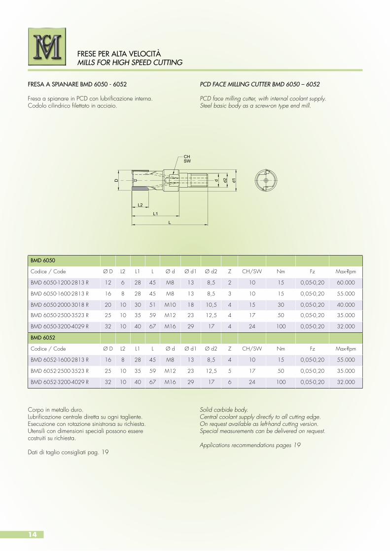
FRESA A SPIANARE BMD 6050 - 6052
Fresa a spianare in PCD con lubrificazione interna.Codolo cilindrico filettato in acciaio.
PCD FACE MILLING CUTTER BMD 6050 – 6052
PCD face milling cutter, with internal coolant supply.Steel basic body as a screw-on type end mill.
CHSW
L
L1
L2
D d1d2d
Corpo in metallo duro.Lubrificazione centrale diretta su ogni tagliente.Esecuzione con rotazione sinistrorsa su richiesta.Utensili con dimensioni speciali possono esserecostruiti su richiesta.
Dati di taglio consigliati pag. 19
Solid carbide body.Central coolant supply directly to all cutting edge.On request available as left-hand cutting version.Special measurements can be delivered on request.
Applications recommendations pages 19
BMD 6050
Codice / Code Ø D L2 L1 L Ø d Ø d1 Ø d2 Z CH/SW Nm Fz Max-Rpm
BMD 6050-1200-2813 R 12 6 28 45 M8 13 8,5 2 10 15 0,05-0,20 60.000
BMD 6050-1600-2813 R 16 8 28 45 M8 13 8,5 3 10 15 0,05-0,20 55.000
BMD 6050-2000-3018 R 20 10 30 51 M10 18 10,5 4 15 30 0,05-0,20 40.000
BMD 6050-2500-3523 R 25 10 35 59 M12 23 12,5 4 17 50 0,05-0,20 35.000
BMD 6050-3200-4029 R 32 10 40 67 M16 29 17 4 24 100 0,05-0,20 32.000
BMD 6052
Codice / Code Ø D L2 L1 L Ø d Ø d1 Ø d2 Z CH/SW Nm Fz Max-Rpm
BMD 6052-1600-2813 R 16 8 28 45 M8 13 8,5 4 10 15 0,05-0,20 55.000
BMD 6052-2500-3523 R 25 10 35 59 M12 23 12,5 5 17 50 0,05-0,20 35.000
BMD 6052-3200-4029 R 32 10 40 67 M16 29 17 6 24 100 0,05-0,20 32.000
FRESE PER ALTA VELOCITÀMILLS FOR HIGH SPEED CUTTING

15
D d H
6
L (±0,02)
L1
FRESA A SPIANARE BMD 5050 – 5052 Fresa a spianare in PCD con lubrificazione interna,attacco a manicotto secondo ISO 6442.Possibilità di asportazione fino a 10 mm.L’elevato numero dei taglienti consente avanzamenti elevati.
PCD FACE MILLING CUTTER BMD 5050- 5052
PCD face milling cutter, with internal coolant supply,shaft according to ISO 6442.Depth of cut up to 10 mm, high fed rate are achieved,thanks to the large number of teeth.
Corpo in metallo duro.Lubrificazione centrale diretta su ogni tagliente.Esecuzione con rotazione sinistrorsa su richiesta.Utensili con dimensioni speciali possono esserecostruiti su richiesta.
Dati di taglio consigliati pag. 19
Solid carbide body.Central coolant supply directly to all cutting edge.On request available as left-hand cutting version.Special measurements can be delivered on request.
Applications recommendations page 19
BMD 5050
Codice / Code Ø D L1 L Ø d Z Fz Max Rpm
BMD 5050-4000-4016 R 40 12 40 16 6 0,05-0,20 28.000
BMD 5050-5000-4022 R 50 12 40 22 8 0,05-0,20 26.000
BMD 5050-6300-4022 R 63 12 40 22 8 0,05-0,20 25.000
BMD 5050-8000-5027 R 80 12 50 27 8 0,05-0,20 20.000
BMD 5050-1000-5032 R 100 12 50 32 10 0,05-0,20 18.000
BMD 5050-1250-6340 R 125 12 63 40 12 0,05-0,20 16.000
BMD 5052
Codice / Code Ø D L1 L Ø d Z Fz Max Rpm
BMD 5052-4000-4016 R 40 12 40 16 10 0,05-0,20 28.000
BMD 5052-5000-4022 R 50 12 40 22 12 0,05-0,20 26.000
BMD 5052-6300-4022 R 63 12 40 22 14 0,05-0,20 25.000
BMD 5052-8000-5027 R 80 12 50 27 16 0,05-0,20 20.000
BMD 5052-1000-5032 R 100 12 50 32 18 0,05-0,20 18.000
BMD 5052-1250-6340 R 125 12 63 40 22 0,05-0,20 16.000
FRESE PER ALTA VELOCITÀMILLS FOR HIGH SPEED CUTTING

16
HSK
ISO 12164 - 1FORMA A - STYLE A
D
L1
L (±0.02)
Corpo in metallo duro.Lubrificazione centrale diretta su ogni tagliente.Esecuzione con rotazione sinistrorsa su richiesta.Utensili con dimensioni speciali possono esserecostruiti su richiesta.
Dati di taglio consigliati pag. 19
Solid carbide body.Central coolant supply directly to all cutting edge.On request available as left-hand cutting version.Special measurements can be delivered on request.
Applications recommendations page 19
BMD 8050
Codice / Code Ø D HSK L1 L Z Fz Max Rpm
BMD 8050-3200- 1063 R 32 63 12 100 6 0,05-0,20 32.000
BMD 8050-4000 -1063 R 40 63 12 100 6 0,05-0,20 28.000
BMD 8050-5000-1063 R 50 63 12 100 8 0,05-0,20 26.000
BMD 8050-6300-1063 R 63 63 12 100 8 0,05-0,20 25.000
BMD 8050-8000-1063 R 80 63 12 100 8 0,05-0,20 20.000
BMD 8050-1000-1063 R 100 63 12 100 10 0,05-0,20 18.000
BMD 8050-1250-1063 R 125 63 12 100 12 0,05-0,20 16.000
BMD 8052
Codice / Code Ø D HSK L1 L Z Fz Max Rpm
BMD 8052-3200- 1063 R 32 63 12 100 8 0,05-0,20 32.000
BMD 8052-4000 -1063 R 40 63 12 100 10 0,05-0,20 28.000
BMD 8052-5000-1063 R 50 63 12 100 12 0,05-0,20 26.000
BMD 8052-6300-1063 R 63 63 12 100 14 0,05-0,20 25.000
BMD 8052-8000-1063 R 80 63 12 100 16 0,05-0,20 20.000
BMD 8052-1000-1063 R 100 63 12 100 18 0,05-0,20 18.000
BMD 8052-1250-1063 R 125 63 12 100 22 0,05-0,20 16.000
FRESA A SPIANARE TIPO BMD 8050 – 8052 Fresa a spianare in PCD con lubrificazione interna, con attacco HSK secondo ISO 12641-1. Possibilità di asportazione fino a 10 mm.L’elevato numero dei taglienti consente avanzamenti elevati.
PCD FACE MILLING CUTTER BMD 8050 - 8052
PCD face milling cutter with internal coolantsupply, HSK-A shaft according to ISO 12614-1.Depth of cut up to 10 mm., high feed rate are achieved,thanks to the large number of teeth.
FRESE PER ALTA VELOCITÀMILLS FOR HIGH SPEED CUTTING
17
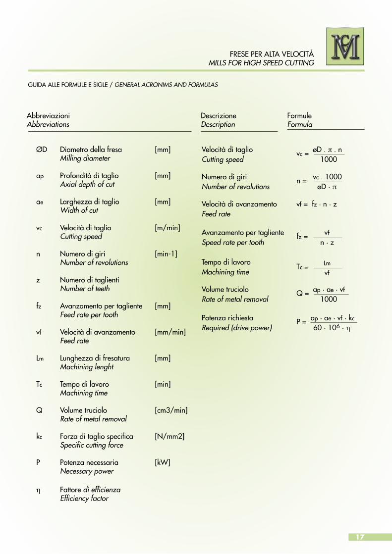
GUIDA ALLE FORMULE E SIGLE / GENERAL ACRONIMS AND FORMULAS
FRESE PER ALTA VELOCITÀMILLS FOR HIGH SPEED CUTTING
ØD Diametro della fresa [mm] Milling diameter
ap Profondità di taglio [mm] Axial depth of cut
ae Larghezza di taglio [mm] Width of cut
vc Velocità di taglio [m/min] Cutting speed
n Numero di giri [min-1] Number of revolutions
z Numero di taglienti Number of teeth
fz Avanzamento per tagliente [mm] Feed rate per tooth
vf Velocità di avanzamento [mm/min] Feed rate
Lm Lunghezza di fresatura [mm] Machining lenght
Tc Tempo di lavoro [min] Machining time
Q Volume truciolo [cm3/min] Rate of metal removal
kc Forza di taglio specifica [N/mm2] Specific cutting force
P Potenza necessaria [kW] Necessary power
η Fattore di efficienza Efficiency factor
Velocità di taglio vc = øD . π . nCutting speed 1000
Numero di giri n = vc . 1000Number of revolutions øD . π Velocità di avanzamento vf = fz . n . z Feed rate
Avanzamento per tagliente fz = vf
Speed rate per tooth n . z
Tempo di lavoro Tc = Lm
Machining time vf
Volume truciolo Q = ap . ae . vf
Rate of metal removal 1000
Potenza richiesta P = ap . ae . vf . kc
Required (drive power) 60 . 106 . η
AbbreviazioniAbbreviations
DescrizioneDescription
FormuleFormula
18
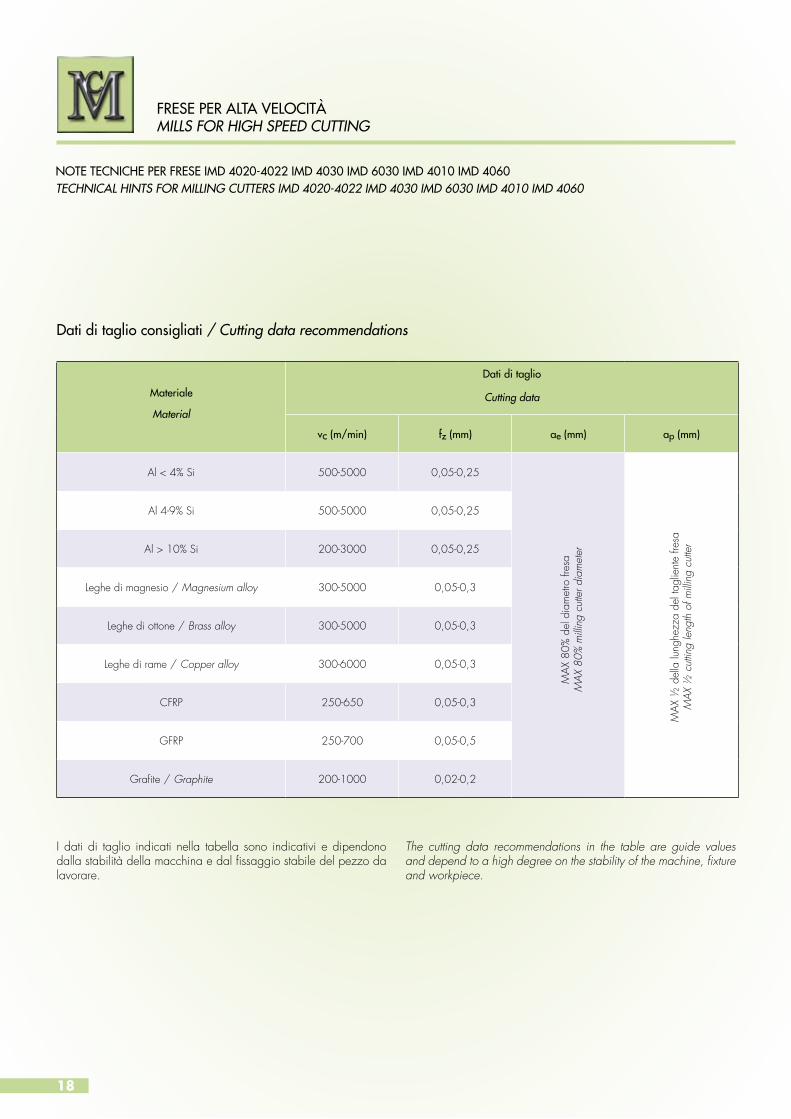
NOTE TECNICHE PER FRESE IMD 4020-4022 IMD 4030 IMD 6030 IMD 4010 IMD 4060TECHNICAL HINTS FOR MILLING CUTTERS IMD 4020-4022 IMD 4030 IMD 6030 IMD 4010 IMD 4060
I dati di taglio indicati nella tabella sono indicativi e dipendono dalla stabilità della macchina e dal fissaggio stabile del pezzo da lavorare.
The cutting data recommendations in the table are guide values and depend to a high degree on the stability of the machine, fixture and workpiece.
FRESE PER ALTA VELOCITÀMILLS FOR HIGH SPEED CUTTING
Materiale
Material
Dati di taglio
Cutting data
vc (m/min) fz (mm) ae (mm) ap (mm)
Al < 4% Si 500-5000 0,05-0,25
MAX
80%
del
dia
met
ro fr
esa
MAX
80%
milli
ng c
utte
r dia
met
er
MAX
½ d
ella
lung
hezz
a de
l tag
lient
e fre
saM
AX ½
cut
ting
leng
th o
f milli
ng c
utte
r
Al 4-9% Si 500-5000 0,05-0,25
Al > 10% Si 200-3000 0,05-0,25
Leghe di magnesio / Magnesium alloy 300-5000 0,05-0,3
Leghe di ottone / Brass alloy 300-5000 0,05-0,3
Leghe di rame / Copper alloy 300-6000 0,05-0,3
CFRP 250-650 0,05-0,3
GFRP 250-700 0,05-0,5
Grafite / Graphite 200-1000 0,02-0,2
Dati di taglio consigliati / Cutting data recommendations

19
NOTE TECNICHE PER FRESE IMD 4050-4052 IMD 6050-6052 IMD 5050-5052 IMD 8050-8052TECHNICAL HINTS FOR MILLING CUTTERS IMD 4050-4052 IMD 6050-6052 IMD 5050-5052 IMD 8050-8052
I dati di taglio indicati nella tabella sono indicativi e dipendono dalla stabilità della macchina e dal fissaggio stabile del pezzo da lavorare.
The cutting data recommendations in the table are guide values and depend to a high degree on the stability of the machine, fixture and workpiece.
FRESE PER ALTA VELOCITÀMILLS FOR HIGH SPEED CUTTING
Materiale
Material
Dati di taglio
Cutting data
vc (m/min) fz (mm) ae (mm) ap (mm)
Al < 4% Si 500-5000 0,05-0,25
MAX
80%
del
dia
met
ro fr
esa
MAX
80%
milli
ng c
utte
r dia
met
er
MAX
2/3
del
la lu
nghe
zza
del t
aglie
nte
fresa
MAX
2/3
cut
ting
leng
th o
f milli
ng c
utte
r
Al 4-9% Si 500-5000 0,05-0,25
Al > 10% Si 200-3000 0,05-0,25
Leghe di magnesio / Magnesium alloy 300-5000 0,05-0,3
Leghe di ottone / Brass alloy 300-5000 0,05-0,3
Leghe di rame / Copper alloy 300-6000 0,05-0,3
CFRP 250-800 0,05-0,15
GFRP 250-800 0,05-0,2
Grafite / Graphite 200-1000 0,02-0,2
Dati di taglio consigliati / Cutting data recommendations

20
FRESE PER ALTA VELOCITÀMILLS FOR HIGH SPEED CUTTING
ESEMPI DI LAVORAZIONE / APPLICATION EXAMPLESO
20±0
,05
R0,4
5045
95
O20
0 -0,0
11 h
6
22
Pezzo da lavorare / Workpiece Corpo pompa ad ingranaggi / Gear pump housing
Materiale / Material Ghisa G 25 / Cast Iron G 25
Lavorazione / Machining Fresatura di spiantura e contornatura sedi / Face and circular milling of the sea
Utensile / Tool Fresa per spianatura e contornatura BMD - 090123 Dia. 20 Face and circular milling cutter BMD - 090123 Dia. 20
Numero taglienti / Number of teeth Z = 7
Tagliente / Cutting edge PCBN
Velocità di taglio / Cutting speed Vc = 722 m. / min.
Numero di giri / RPM n = 11.500 1 /min.
Avanzamento / Feed rate Vf = 4.025 mm. / min.
Avanz. per tagliente / Feed rate per tooth fz = 0,05 mm.
Refrigerante / Internal coolant no / no
Risultati / Results Rugosità / Roughness Ra = 0,5
21
FRESE PER ALTA VELOCITÀMILLS FOR HIGH SPEED CUTTING
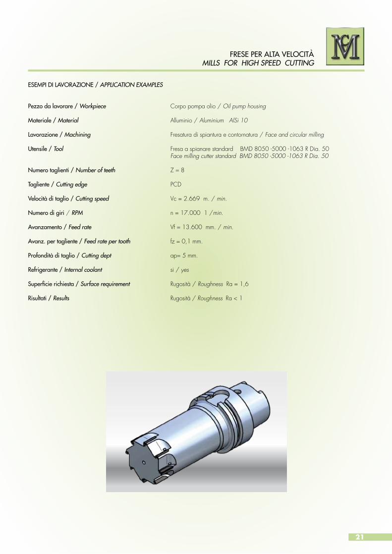
ESEMPI DI LAVORAZIONE / APPLICATION EXAMPLES
Pezzo da lavorare / Workpiece Corpo pompa olio / Oil pump housing
Materiale / Material Alluminio / Aluminium AlSi 10
Lavorazione / Machining Fresatura di spiantura e contornatura / Face and circular milling
Utensile / Tool Fresa a spianare standard BMD 8050 -5000 -1063 R Dia. 50 Face milling cutter standard BMD 8050 -5000 -1063 R Dia. 50
Numero taglienti / Number of teeth Z = 8
Tagliente / Cutting edge PCD
Velocità di taglio / Cutting speed Vc = 2.669 m. / min.
Numero di giri / RPM n = 17.000 1 /min.
Avanzamento / Feed rate Vf = 13.600 mm. / min.
Avanz. per tagliente / Feed rate per tooth fz = 0,1 mm.
Profondità di taglio / Cutting dept ap= 5 mm.
Refrigerante / Internal coolant si / yes
Superficie richiesta / Surface requirement Rugosità / Roughness Ra = 1,6
Risultati / Results Rugosità / Roughness Ra < 1
22
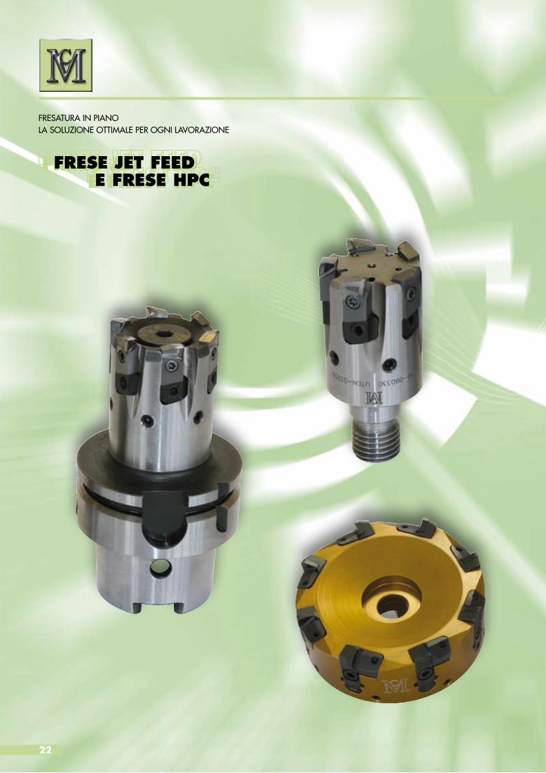
FRESATURA IN PIANOLA SOLUZIONE OTTIMALE PER OGNI LAVORAZIONE
FRESE JET FEED E FRESE HPCFRESE JET FEED E FRESE HPC

23
FLAT MILLINGTHE OPTIMAL SOLUTION FOR EVERY MACHINING
JET FEED MILLS HPC MILLSJET FEED MILLS HPC MILLS
24
FRESE JET FEEDJET FEED MILLS
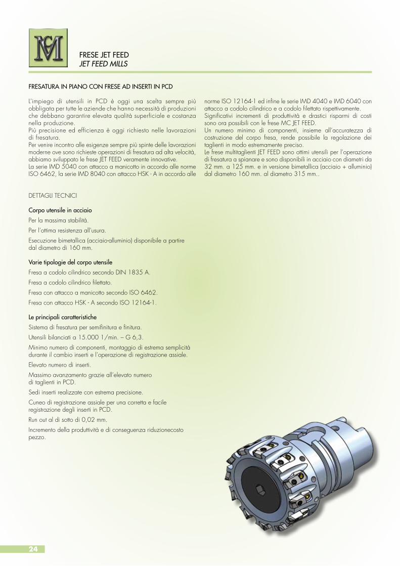
FRESATURA IN PIANO CON FRESE AD INSERTI IN PCD
L’impiego di utensili in PCD è oggi una scelta sempre più obbligata per tutte le aziende che hanno necessità di produzioni che debbano garantire elevata qualità superficiale e costanza nella produzione.Più precisione ed efficienza è oggi richiesto nelle lavorazioni di fresatura.Per venire incontro alle esigenze sempre più spinte delle lavorazioni moderne ove sono richieste operazioni di fresatura ad alta velocità, abbiamo sviluppato le frese JET FEED veramente innovative.La serie IMD 5040 con attacco a manicotto in accordo alle norme ISO 6462, la serie IMD 8040 con attacco HSK - A in accordo alle
norme ISO 12164-1 ed infine le serie IMD 4040 e IMD 6040 con attacco a codolo cilindrico e a codolo filettato rispettivamente.Significativi incrementi di produttività e drastici risparmi di costi sono ora possibili con le frese MC JET FEED.Un numero minimo di componenti, insieme all’accuratezza di costruzione del corpo fresa, rende possibile la regolazione dei taglienti in modo estremamente preciso.Le frese multitaglienti JET FEED sono ottimi utensili per l’operazione di fresatura a spianare e sono disponibili in acciaio con diametri da 32 mm. a 125 mm. e in versione bimetallica (acciaio + alluminio) dal diametro 160 mm. al diametro 315 mm..
DETTAGLI TECNICI
Corpo utensile in acciaio
Per la massima stabilità.
Per l’ottima resistenza all’usura.
Esecuzione bimetallica (acciaio-alluminio) disponibile a partiredal diametro di 160 mm.
Varie tipologie del corpo utensile
Fresa a codolo cilindrico secondo DIN 1835 A.
Fresa a codolo cilindrico filettato.
Fresa con attacco a manicotto secondo ISO 6462.
Fresa con attacco HSK - A secondo ISO 12164-1.
Le principali caratteristiche
Sistema di fresatura per semifinitura e finitura.
Utensili bilanciati a 15.000 1/min. – G 6,3.
Minimo numero di componenti, montaggio di estrema semplicitàdurante il cambio inserti e l’operazione di registrazione assiale.
Elevato numero di inserti.
Massimo avanzamento grazie all’elevato numerodi taglienti in PCD.
Sedi inserti realizzate con estrema precisione.
Cuneo di registrazione assiale per una corretta e facile registrazione degli inserti in PCD.
Run out al di sotto di 0,02 mm.
Incremento della produttività e di conseguenza riduzionecostopezzo.

25
TECHNICAL SPECIFICATIONS
Steel tool body
For highest stability.
For maximum abrasion resistance.
Bimetallic version (steel and aluminum) available starting froma diameter of 160 mm.
Various types of tool body
Milling cutters with cylindrical shaft according to DIN 1835 A.
Screw-on type end mill.
Milling cutter shaft according to ISO 6462.
Milling cutter with HSK - A shaft according to ISO 12164-1.
The main features
Milling finish and semi-finish system.
A minimum of components, easy handling and adjustability during the changing of inserts and adjustment axial operation.
Tools balanced to G 6,3 at 15.000 1/min.
Extremely high number of inserts.
High feed rate due to a high number of PCD inserts.
Higly exact insert pocket.
Sensitive adjusting wedge for a correct and easy adjustmentof the PCD inserts.
Run out under 0,02 mm.
Increase productivity and therefore reduced cost per part.
FRESE JET FEED JET FEED MILLS
The use of PCD tools is now an increasingly more mandatory requirement for companies who need to guarantee perfect surface finish and consistency in production. Higher precision and efficiency is now required in milling process. To meet the increasing demands due to modern machining where high-speed milling is required, we have developed the truly innovative JET FEED mills.The IMD 5040 series with clamp fixing in accordance withISO 6462, the IMD 8040 series with HSK - A in accordance with ISO 12164-1, and finally the IMD 4040 and IMD 6040 series with a cylindrical shaft and a screw-on type shaft respectively.
Significant increases in productivity and important cost savings are now possible with MC JET FEED mills.A minimal number of components, together with the accurate construction of the body, make it possible to adjust the cutting edges in an extremely precise manner.The JET FEED multi-cut mills are excellent tools for milling operation and are available in steel with diameters ranging from 32 to125 mm. and a bimetallic (steel and aluminium) version with diameters ranging from 160 to 315 mm..
FLAT MILLING CUTTERS WITH PCD INSERTS
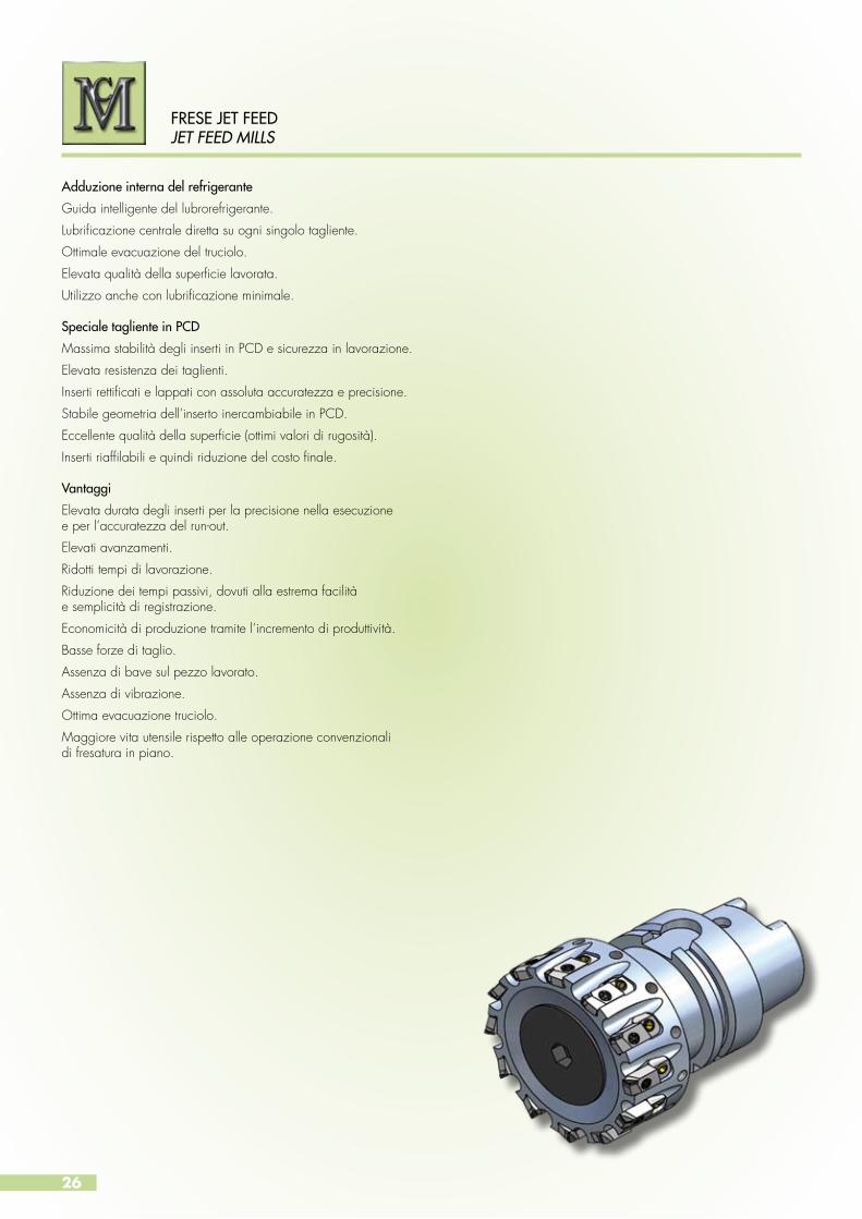
Adduzione interna del refrigerante
Guida intelligente del lubrorefrigerante.
Lubrificazione centrale diretta su ogni singolo tagliente.
Ottimale evacuazione del truciolo.
Elevata qualità della superficie lavorata.
Utilizzo anche con lubrificazione minimale.
Speciale tagliente in PCD
Massima stabilità degli inserti in PCD e sicurezza in lavorazione.
Elevata resistenza dei taglienti.
Inserti rettificati e lappati con assoluta accuratezza e precisione.
Stabile geometria dell’inserto inercambiabile in PCD.
Eccellente qualità della superficie (ottimi valori di rugosità).
Inserti riaffilabili e quindi riduzione del costo finale.
Vantaggi
Elevata durata degli inserti per la precisione nella esecuzionee per l’accuratezza del run-out.
Elevati avanzamenti.
Ridotti tempi di lavorazione.
Riduzione dei tempi passivi, dovuti alla estrema facilitàe semplicità di registrazione.
Economicità di produzione tramite l’incremento di produttività.
Basse forze di taglio.
Assenza di bave sul pezzo lavorato.
Assenza di vibrazione.
Ottima evacuazione truciolo.
Maggiore vita utensile rispetto alle operazione convenzionali di fresatura in piano.
26
FRESE JET FEEDJET FEED MILLS
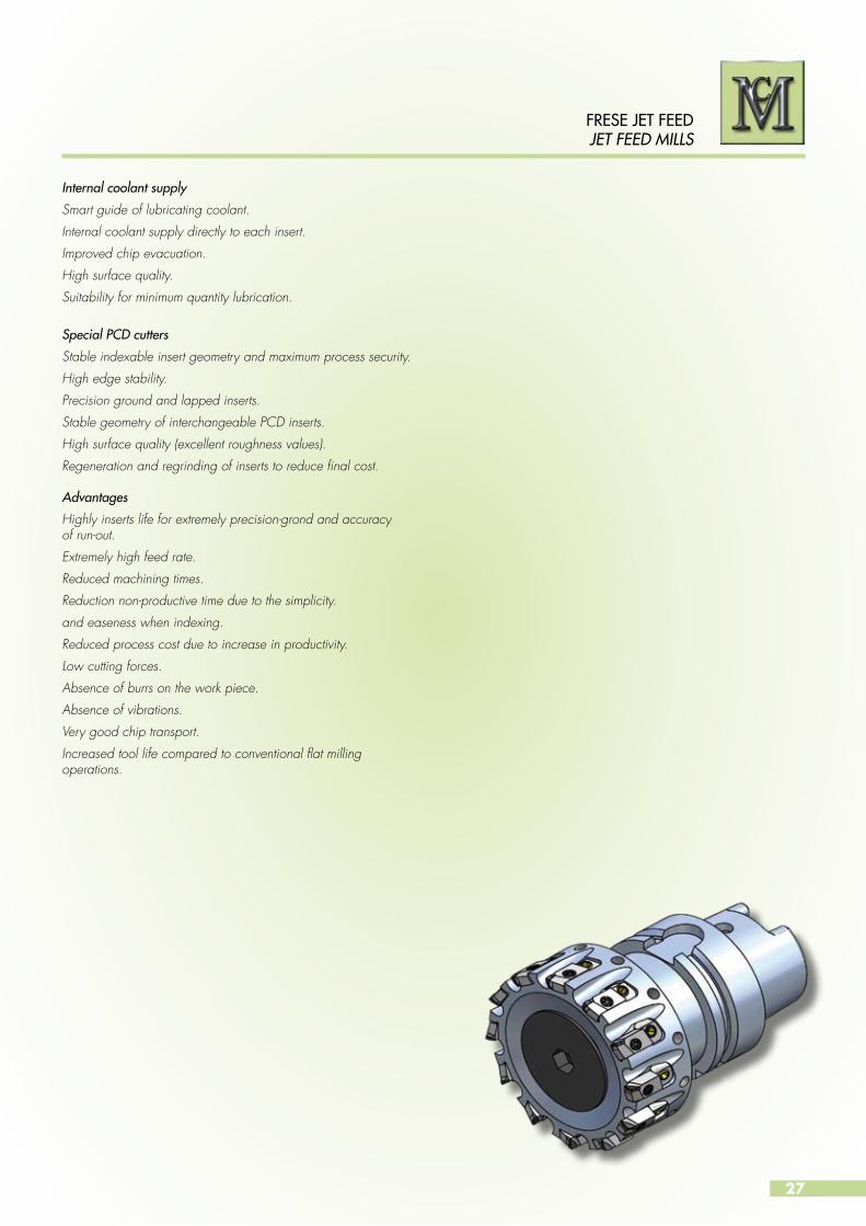
Internal coolant supply
Smart guide of lubricating coolant.
Internal coolant supply directly to each insert.
Improved chip evacuation.
High surface quality.
Suitability for minimum quantity lubrication.
Special PCD cutters
Stable indexable insert geometry and maximum process security.
High edge stability.
Precision ground and lapped inserts.
Stable geometry of interchangeable PCD inserts.
High surface quality (excellent roughness values).
Regeneration and regrinding of inserts to reduce final cost.
Advantages
Highly inserts life for extremely precision-grond and accuracyof run-out.
Extremely high feed rate.
Reduced machining times.
Reduction non-productive time due to the simplicity.
and easeness when indexing.
Reduced process cost due to increase in productivity.
Low cutting forces.
Absence of burrs on the work piece.
Absence of vibrations.
Very good chip transport.
Increased tool life compared to conventional flat milling operations.
27
FRESE JET FEED JET FEED MILLS

28
DETTAGLI TECNICI
Corpo utensile in acciaio
Per la massima stabilità.
Per l’ottima resistenza all’usura.
Esecuzione bimetallica (acciaio-alluminio) disponibile a partiredal diametro di 160 mm.
Varie tipologie del corpo utensile
Fresa a codolo cilindrico secondo DIN 1835 A.
Fresa a codolo cilindrico filettato.
Fresa con attacco a manicotto secondo ISO 6462.
Fresa con attacco HSK - A secondo ISO 12164-1.
Caratteristiche
Lavorazione ad alta velocità.
Ottima qualità superficiale.
Inserti riaffilabili e quindi risduzione del costo finale.
Costi operativi ridotti grazie ai dati di taglio elevati ed all’economicità
del costo dell’inserto.
Condizioni di taglio raccomandate
Velocità: 600 - 2000 m/min.
Avanzamento: fz 0,1 - 0,3 mm./tagliente.
Profondità di taglio: ap = 0,5 o inferiore.
Lavorazione a secco.
Le frese JET FEED della serie IMD 4040, IMD 6040, IMD 5040, IMD 3040, IMD 8040 sono estremamente indicate anche per la fresatura di finitura ad alta velocità delle ghise. Cambiando semplicemente il tipo di inserto, questi utensili possono essere impiegati indifferentemente per la fresatura delle leghe leggere e delle ghise. Per la finitura ad alta velocità delle ghise generalmente vengono utilizzati inserti in PCBN.
Nelle pagine seguenti sono indicate le geometrie degli inserti e la selezione dei gradi per le varie applicazioni.A pagina 45 sono invece indicati i dati di taglio consigliati.
FINITURA AD ALTA VELOCITA’ DELLA GHISA
FRESE JET FEEDJET FEED MILLS

29
TECHNICAL SPECIFICATIONS
Steel tool body
For highest stability.
For maximum abrasion resistance.
Bimetallic version (steel and aluminium) available starting from
a diameter of 160 mm.
Various types of tool body
Milling cutters with cylindrical shaft according to DIN 1835 A.
Screw-on type end mill.
Milling cutter shaft according to ISO 6462.
Milling cutter with HSK - A shaft according to ISO 12164-1.
Characteristics
High-speed machining.
Extremely high surface quality.
Regeneration and regrinding of inserts to reduce final cost.
Operating costs reduced by high feed data and the low of cost of
the inserts.
Recommended cutting conditions
Speed: 600 - 2000 m/min.
Feed: fz 0,1 - 0,3 mm./cutting edge.
Cut depth: ap = 0,5 or inferior.
Dry machining.
The JET FEED mills, series IMD 4040, IMD 6040, IMD 5040, IMD 3040 and IMD 8040, are also highly suitable for high-speed milling of cast iron. These tools can be used for both milling of light alloys and cast iron by simply changing the type of insert. PCBN inserts are generally used for high-speed finishing of cast irons.
The geometry and grade selection of the inserts for various applications are shown in the following pages.On the other hand, the recommended cutting data can be visualized on page 45.
HIGH-SPEED FINISH OF CAST IRON
FRESE JET FEED JET FEED MILLS

30
FRESE JET FEEDJET FEED MILLS
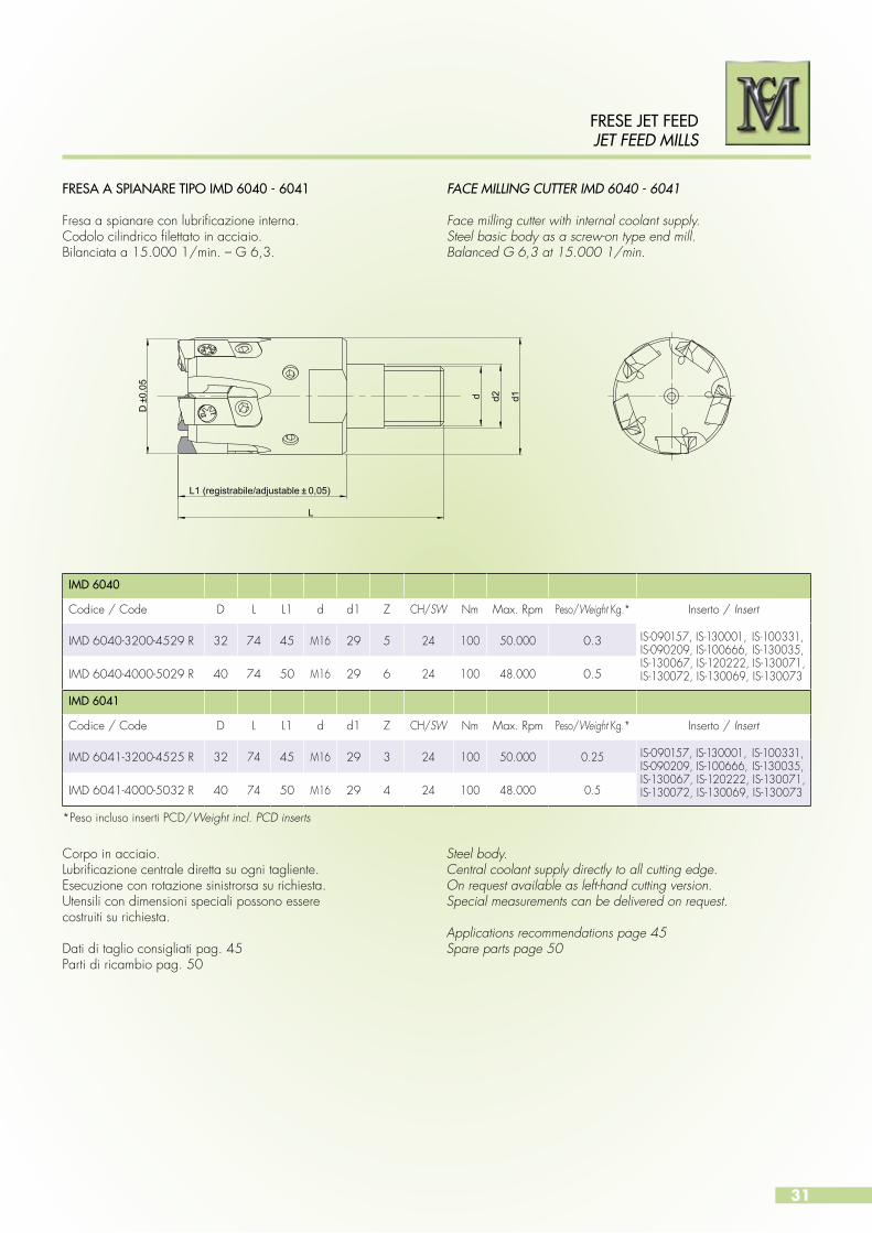
FRESA A SPIANARE TIPO IMD 4040 - 4041
Fresa a spianare con lubrificazione interna.Codolo cilindrico in acciaio secondo DIN 1835 A.Bilanciata a 15.000 1/min. – G 6,3.
FACE MILLING CUTTER IMD 4040 - 4041
Face milling cutter with internal coolant supply.Steel basic body,cilindrical shaft according to DIN 1835 A. Balanced G 6,3 at 15.000 1/min.
L1 (registrabile/adjustable ±0,05)
D±0
,05
d h6
L
Corpo in acciaio.Lubrificazione centrale diretta su ogni tagliente.Esecuzione con rotazione sinistrorsa su richiesta.Utensili con dimensioni speciali possono esserecostruiti su richiesta.
Dati di taglio consigliati pag. 45Parti di ricambio pag. 50
Steel body.Central coolant supply directly to all cutting edge.On request available as left-hand cutting version.Special measurements can be delivered on request.
Applications recommendations page 45Spare parts page 50
IMD 4040
Codice / Code D L L1 d Z Max. Rpm Peso/Weight Kg.* Inserto / Insert
IMD 4040-3200-4525 R 32 101 45 25 5 50.000 0.5 IS-090157, IS-130001, IS-100331,IS-090209, IS-100666, IS-130035,IS-130067, IS-120222, IS-130071,IS-130072, IS-130069, IS-130073IMD 4040-4000-5032 R 40 106 50 32 6 48.000 0.8
IMD 4041
Codice / Code D L L1 d Z Max. Rpm Peso/Weight Kg.* Inserto / Insert
IMD 4041-3200-4525 R 32 101 45 25 3 50.000 0.4 IS-090157, IS-130001, IS-100331,IS-090209, IS-100666, IS-130035,IS-130067, IS-120222, IS-130071,IS-130072, IS-130069, IS-130073IMD 4041-4000-5032 R 40 106 50 32 4 48.000 0.7
*Peso incluso inserti PCD/Weight incl. PCD inserts
31
FRESE JET FEED JET FEED MILLS
L1 (registrabile/adjustable ± 0,05)
D ±
0,05
L
d d2 d1
IMD 6040
Codice / Code D L L1 d d1 Z CH/SW Nm Max. Rpm Peso/Weight Kg.* Inserto / Insert
IMD 6040-3200-4529 R 32 74 45 M16 29 5 24 100 50.000 0.3 IS-090157, IS-130001, IS-100331,IS-090209, IS-100666, IS-130035,IS-130067, IS-120222, IS-130071,IS-130072, IS-130069, IS-130073IMD 6040-4000-5029 R 40 74 50 M16 29 6 24 100 48.000 0.5
IMD 6041
Codice / Code D L L1 d d1 Z CH/SW Nm Max. Rpm Peso/Weight Kg.* Inserto / Insert
IMD 6041-3200-4525 R 32 74 45 M16 29 3 24 100 50.000 0.25 IS-090157, IS-130001, IS-100331,IS-090209, IS-100666, IS-130035,IS-130067, IS-120222, IS-130071,IS-130072, IS-130069, IS-130073IMD 6041-4000-5032 R 40 74 50 M16 29 4 24 100 48.000 0.5
FRESA A SPIANARE TIPO IMD 6040 - 6041 Fresa a spianare con lubrificazione interna.Codolo cilindrico filettato in acciaio.Bilanciata a 15.000 1/min. – G 6,3.
FACE MILLING CUTTER IMD 6040 - 6041
Face milling cutter with internal coolant supply.Steel basic body as a screw-on type end mill.Balanced G 6,3 at 15.000 1/min.
Corpo in acciaio.Lubrificazione centrale diretta su ogni tagliente.Esecuzione con rotazione sinistrorsa su richiesta.Utensili con dimensioni speciali possono esserecostruiti su richiesta.
Dati di taglio consigliati pag. 45Parti di ricambio pag. 50
Steel body.Central coolant supply directly to all cutting edge.On request available as left-hand cutting version.Special measurements can be delivered on request.
Applications recommendations page 45Spare parts page 50
*Peso incluso inserti PCD/Weight incl. PCD inserts

32
FRESE JET FEEDJET FEED MILLS
FRESA A SPIANARE TIPO IMD 5040
Fresa a spianare con lubrificazione interna.Attacco a manicotto secondo ISO 6462.Bilanciata a 15.000 1/min. – G 6,3.
FACE MILLING CUTTER IMD 5040
Face milling cutter with internal coolant supply.Shaft according to ISO 6462.Balanced G 6,3 at 15.000 1/min.
L (registrabile/adjustable ± 0,05)
D d H
6
Corpo in acciaio. Lubrificazione centrale diretta su ogni taglientetramite vite distribuzione refrigerante.Utensili con rotazione sinistrorsa e con dimensionispeciali possono essere costruiti su richiesta.
Dati di taglio consigliati pag. 45Parti di ricambio pag. 50
Steel body.Central coolant supply directly to all cutting edgeby a coolant distribution screw.As left-hand cutting version and special measurementscan be delivered on request.
Applications recommendations page 45Spare parts page 50
IMD 5040
Codice / Code D L d Z Max. Rpm Peso/Weight Kg.* Inserto / Insert
IMD 5040-4000-5016 R 40 50 16 6 48.000 0.4 IS-090157, IS-130001, IS-100331,IS-090209, IS-100666, IS-130035,IS-130067, IS-120222, IS-130071,IS-130072, IS-130069, IS-130073 IMD 5040-5000-5022 R 50 50 22 8 45.000 0.6
IMD 5040-6300-5022 R 63 50 22 8 41.000 0.9
IS-080329, IS-110029, IS-110074,IS-100640, IS-080381, IS-120288,IS-130068, IS-080378, IS-130074,IS-130075, IS-130070, IS-130076
IMD 5040-8000-5027 R 80 50 27 12 36.000 1.4
IMD 5040-1000-5032 R 100 50 32 16 31.000 2
IMD 5040-1250-6340 R 125 63 40 20 23.000 3.3
*Peso incluso inserti PCD/Weight incl. PCD inserts

33
L (registrabile/adjustable ± 0,05)
D d H
6
IMD 5041
Codice / Code D L d Z Max. Rpm Peso/Weight Kg.* Inserto / Insert
IMD 5041-4000-5016 R 40 50 16 4 48.000 0.3 IS-090157, IS-130001, IS-100331,IS-090209, IS-100666, IS-130035,IS-130067, IS-120222, IS-130071,IS-130072, IS-130069, IS-130073IMD 5041-5000-5022 R 50 50 22 5 45.000 0.55
IMD 5041-6300-5022 R 63 50 22 6 41.000 0.85
IS-080329, IS-110029, IS-110074,IS-100640, IS-080381, IS-120288,IS-130068, IS-080378, IS-130074,IS-130075, IS-130070, IS-130076
IMD 5041-8000-5027 R 80 50 27 6 36.000 1.3
IMD 5041-1000-5032 R 100 50 32 8 31.000 1.8
IMD 5041-1250-6340 R 125 63 40 10 23.000 3
FRESE JET FEED JET FEED MILLS
FRESA A SPIANARE TIPO IMD 5041
Fresa a spianare con lubrificazione interna.Attacco a manicotto secondo ISO 6462.Bilanciata a 15.000 1/min. – G 6,3
FACE MILLING CUTTER IMD 5041
Face milling cutter, with internal coolant supply.Shaft according to ISO 6462.Balanced G 6,3 at 15.000 1/min.
Corpo in acciaio. Lubrificazione centrale diretta su ogni taglientetramite vite distribuzione refrigerante.Utensili con rotazione sinistrorsa e con dimensionispeciali possono essere costruiti su richiesta.
Dati di taglio consigliati pag. 45Parti di ricambio pag. 50
Steel body.Central coolant supply directly to all cutting edgeby a coolant distribution screw.As left-hand cutting version and special measurementscan be delivered on request.
Applications recommendations page 45Spare parts page 50
*Peso incluso inserti PCD/Weight incl. PCD inserts
34
FRESE JET FEEDJET FEED MILLS
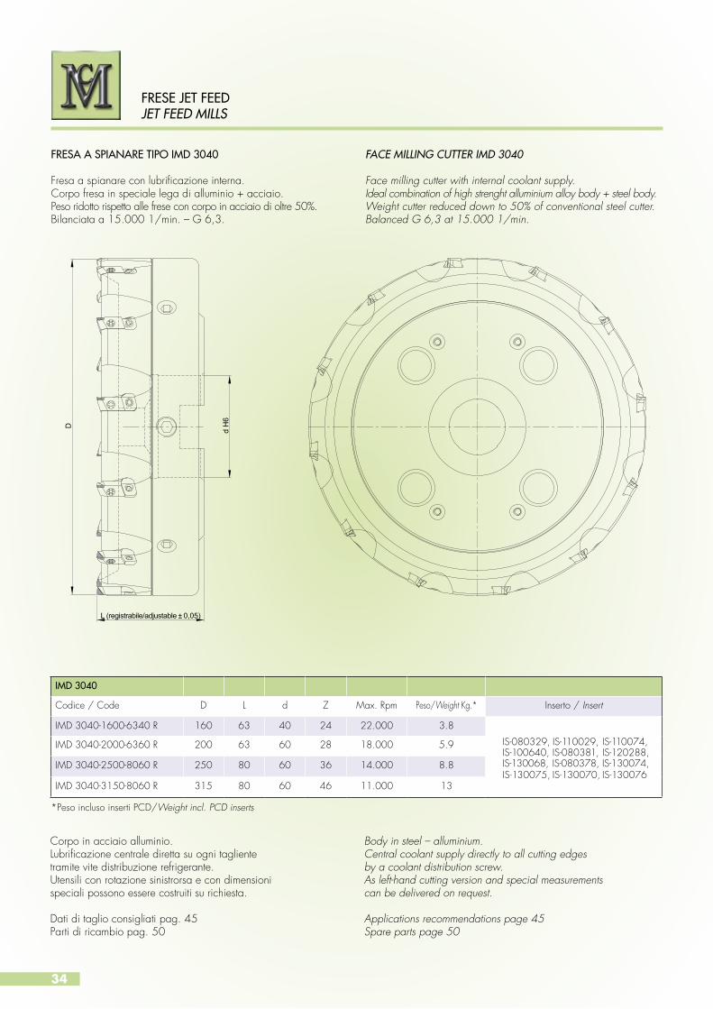
FRESA A SPIANARE TIPO IMD 3040
Fresa a spianare con lubrificazione interna.Corpo fresa in speciale lega di alluminio + acciaio.Peso ridotto rispetto alle frese con corpo in acciaio di oltre 50%.Bilanciata a 15.000 1/min. – G 6,3.
FACE MILLING CUTTER IMD 3040
Face milling cutter with internal coolant supply.Ideal combination of high strenght alluminium alloy body + steel body.Weight cutter reduced down to 50% of conventional steel cutter.Balanced G 6,3 at 15.000 1/min.
L (registrabile/adjustable ± 0,05)
d H
6
D
Corpo in acciaio alluminio.Lubrificazione centrale diretta su ogni taglientetramite vite distribuzione refrigerante.Utensili con rotazione sinistrorsa e con dimensionispeciali possono essere costruiti su richiesta.
Dati di taglio consigliati pag. 45Parti di ricambio pag. 50
Body in steel – alluminium.Central coolant supply directly to all cutting edgesby a coolant distribution screw.As left-hand cutting version and special measurementscan be delivered on request.
Applications recommendations page 45Spare parts page 50
IMD 3040
Codice / Code D L d Z Max. Rpm Peso/Weight Kg.* Inserto / Insert
IMD 3040-1600-6340 R 160 63 40 24 22.000 3.8
IS-080329, IS-110029, IS-110074,IS-100640, IS-080381, IS-120288,IS-130068, IS-080378, IS-130074,IS-130075, IS-130070, IS-130076
IMD 3040-2000-6360 R 200 63 60 28 18.000 5.9
IMD 3040-2500-8060 R 250 80 60 36 14.000 8.8
IMD 3040-3150-8060 R 315 80 60 46 11.000 13
*Peso incluso inserti PCD/Weight incl. PCD inserts
35
L (registrabile/adjustable ± 0,05)
d H
6
D
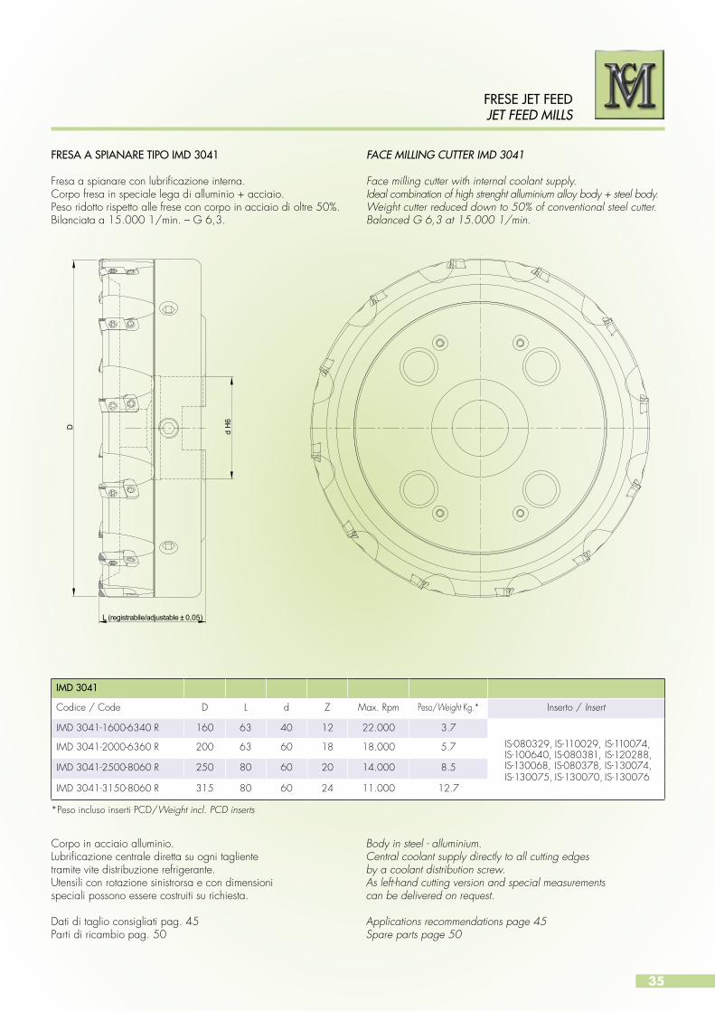
FRESA A SPIANARE TIPO IMD 3041
Fresa a spianare con lubrificazione interna.Corpo fresa in speciale lega di alluminio + acciaio.Peso ridotto rispetto alle frese con corpo in acciaio di oltre 50%.Bilanciata a 15.000 1/min. – G 6,3.
FACE MILLING CUTTER IMD 3041
Face milling cutter with internal coolant supply.Ideal combination of high strenght alluminium alloy body + steel body.Weight cutter reduced down to 50% of conventional steel cutter.Balanced G 6,3 at 15.000 1/min.
Corpo in acciaio alluminio.Lubrificazione centrale diretta su ogni taglientetramite vite distribuzione refrigerante.Utensili con rotazione sinistrorsa e con dimensionispeciali possono essere costruiti su richiesta.
Dati di taglio consigliati pag. 45Parti di ricambio pag. 50
Body in steel - alluminium.Central coolant supply directly to all cutting edgesby a coolant distribution screw.As left-hand cutting version and special measurementscan be delivered on request.
Applications recommendations page 45Spare parts page 50
FRESE JET FEED JET FEED MILLS
IMD 3041
Codice / Code D L d Z Max. Rpm Peso/Weight Kg.* Inserto / Insert
IMD 3041-1600-6340 R 160 63 40 12 22.000 3.7
IS-080329, IS-110029, IS-110074,IS-100640, IS-080381, IS-120288,IS-130068, IS-080378, IS-130074,IS-130075, IS-130070, IS-130076
IMD 3041-2000-6360 R 200 63 60 18 18.000 5.7
IMD 3041-2500-8060 R 250 80 60 20 14.000 8.5
IMD 3041-3150-8060 R 315 80 60 24 11.000 12.7
*Peso incluso inserti PCD/Weight incl. PCD inserts

36
FRESE JET FEEDJET FEED MILLS
FRESA A SPIANARE TIPO IMD 8040
Fresa a spianare con lubrificazione interna.Attacco HSK secondo ISO 12164-1.Bilanciata a 15.000 1/min. – G 6,3.
FACE MILLING CUTTER IMD 8040
Face milling cutter with internal coolant supply.HSK shaft according to ISO 12164-1.Balanced G 6,3 at 15.000 1/min.
ISO 12164 - 1FORMA A - STYLE A
D
L (registrabile/adjustable ±0,05)
HS
K
Corpo in acciaio.Lubrificazione centrale diretta su ogni taglientetramite vite distribuzione refrigerante.Utensili con rotazione sinistrorsa e con dimensioni speciali possono essere costruiti su richiesta.
Dati di taglio consigliati pag. 45Parti di ricambio pag. 50
Steel body.Central coolant supply directly to all cutting edgesby a coolant distribution screw.As left-hand cutting version and special measurementscan be delivered on request.
Applications recommendations page 45Spare parts page 50
IMD 8040
Codice / Code Ø D HSK L Z Max Rpm Peso/Weight Kg.* Inserto / Insert
IMD 8040-3200-8063 R 32 63 80 5 50.000 1.0IS-090157, IS-130001, IS-100331,IS-090209, IS-100666, IS-130035,IS-130067, IS-120222, IS-130071,IS-130072, IS-130069, IS-130073
IMD 8040-4000-8063 R 40 63 80 6 48.000 1.1
IMD 8040-5000-8063 R 50 63 80 8 45.000 1.3
IMD 8040-6300-8063 R 63 63 80 8 41.000 1.7IS-080329, IS-110029, IS-110074,IS-100640, IS-080381, IS-120288,IS-130068, IS-080378, IS-130074,IS-130075, IS-130070, IS-130076
IMD 8040-8000-8063 R 80 63 80 12 36.000 2.1
IMD 8040-1000-8063 R 100 63 80 16 31.000 2.6
IMD 8040-1250-8063 R 125 63 80 20 23.000 3.6
MD 8040-4000-1080 R 40 80 100 6 48.000 2.5 IS-090157, IS-130001, IS-100331,IS-090209, IS-100666, IS-130035,IS-130067, IS-120222, IS-130071,IS-130072, IS-130069, IS-130073IMD 8040-5000-1080 R 50 80 100 8 45.000 2.7
IMD 8040-6300-1080 R 63 80 100 8 41.000 3.4IS-080329, IS-110029, IS-110074,IS-100640, IS-080381, IS-120288,IS-130068, IS-080378, IS-130074,IS-130075, IS-130070, IS-130076
IMD 8040-8000-1080 R 80 80 100 12 36.000 3.5
IMD 8040-1000-1080 R 100 80 100 16 31.000 4
IMD 8040-1250-1080 R 125 80 100 20 23.000 5
*Peso incluso inserti PCD/Weight incl. PCD inserts

37
FRESA A SPIANARE TIPO IMD 8040
Fresa a spianare con lubrificazione internaAttacco HSK secondo ISO 12164-1.Bilanciata a 15.000 1/min. – G 6,3.
FACE MILLING CUTTER IMD 8040
Face milling cutter with internal coolant supply.HSK shaft according to ISO 12164-1.Balanced G 6,3 at 15.000 1/min.
ISO 12164 - 1FORMA A - STYLE A
D
L (registrabile/adjustable ±0,05)
HS
K
Corpo in acciaio.Lubrificazione centrale diretta su ogni taglientetramite vite distribuzione refrigerante.Utensili con rotazione sinistrorsa e con dimensioni speciali possono essere costruiti su richiesta.
Dati di taglio consigliati pag. 45Parti di ricambio pag. 50
Steel body.Central coolant supply directly to all cutting edgesby a coolant distribution screw.As left-hand cutting version and special measurementscan be delivered on request.
Applications recommendations page 45Spare parts page 50
FRESE JET FEED JET FEED MILLS
IMD 8040
Codice / Code Ø D HSK L Z Max Rpm Peso/Weight Kg.* Inserto / Insert
IMD 8040-4000-1210 R 40 100 120 6 48.000 3.1 IS-090157, IS-130001, IS-100331,IS-090209, IS-100666, IS-130035,IS-130067, IS-120222, IS-130071,IS-130072, IS-130069, IS-130073IMD 8040-5000-1210 R 50 100 120 8 45.000 3.3
IMD 8040-6300-1210 R 63 100 120 8 41.000 3.7
IS-080329, IS-110029, IS-110074,IS-100640, IS-080381, IS-120288,IS-130068, IS-080378, IS-130074,IS-130075, IS-130070, IS-130076
IMD 8040-8000-1210 R 80 100 120 12 36.000 4.1
IMD 8040-1000-1210 R 100 100 120 16 31.000 4.6
IMD 8040-1250-1210 R 125 100 120 20 23.000 5.6
IMD 8040-1600-1210 R 160 100 120 24 16.000 6.5
*Peso incluso inserti PCD/Weight incl. PCD inserts
38
FRESE JET FEEDJET FEED MILLS
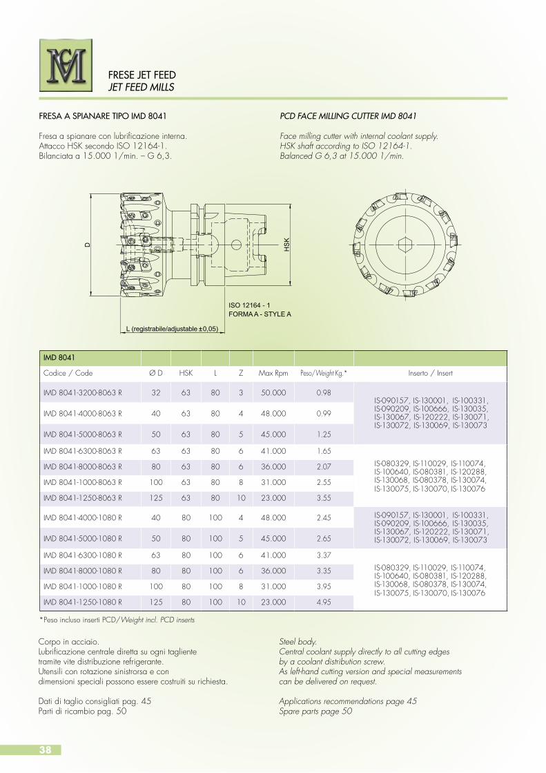
FRESA A SPIANARE TIPO IMD 8041
Fresa a spianare con lubrificazione interna.Attacco HSK secondo ISO 12164-1.Bilanciata a 15.000 1/min. – G 6,3.
PCD FACE MILLING CUTTER IMD 8041
Face milling cutter with internal coolant supply.HSK shaft according to ISO 12164-1.Balanced G 6,3 at 15.000 1/min.
ISO 12164 - 1FORMA A - STYLE A
D
L (registrabile/adjustable ±0,05)
HS
K
Corpo in acciaio.Lubrificazione centrale diretta su ogni taglientetramite vite distribuzione refrigerante.Utensili con rotazione sinistrorsa e con dimensioni speciali possono essere costruiti su richiesta.
Dati di taglio consigliati pag. 45Parti di ricambio pag. 50
Steel body.Central coolant supply directly to all cutting edgesby a coolant distribution screw.As left-hand cutting version and special measurementscan be delivered on request.
Applications recommendations page 45Spare parts page 50
IMD 8041
Codice / Code Ø D HSK L Z Max Rpm Peso/Weight Kg.* Inserto / Insert
IMD 8041-3200-8063 R 32 63 80 3 50.000 0.98IS-090157, IS-130001, IS-100331,IS-090209, IS-100666, IS-130035,IS-130067, IS-120222, IS-130071,IS-130072, IS-130069, IS-130073
IMD 8041-4000-8063 R 40 63 80 4 48.000 0.99
IMD 8041-5000-8063 R 50 63 80 5 45.000 1.25
IMD 8041-6300-8063 R 63 63 80 6 41.000 1.65
IS-080329, IS-110029, IS-110074,IS-100640, IS-080381, IS-120288,IS-130068, IS-080378, IS-130074,IS-130075, IS-130070, IS-130076
IMD 8041-8000-8063 R 80 63 80 6 36.000 2.07
IMD 8041-1000-8063 R 100 63 80 8 31.000 2.55
IMD 8041-1250-8063 R 125 63 80 10 23.000 3.55
IMD 8041-4000-1080 R 40 80 100 4 48.000 2.45 IS-090157, IS-130001, IS-100331,IS-090209, IS-100666, IS-130035,IS-130067, IS-120222, IS-130071,IS-130072, IS-130069, IS-130073IMD 8041-5000-1080 R 50 80 100 5 45.000 2.65
IMD 8041-6300-1080 R 63 80 100 6 41.000 3.37
IS-080329, IS-110029, IS-110074,IS-100640, IS-080381, IS-120288,IS-130068, IS-080378, IS-130074,IS-130075, IS-130070, IS-130076
IMD 8041-8000-1080 R 80 80 100 6 36.000 3.35
IMD 8041-1000-1080 R 100 80 100 8 31.000 3.95
IMD 8041-1250-1080 R 125 80 100 10 23.000 4.95
*Peso incluso inserti PCD/Weight incl. PCD inserts
39
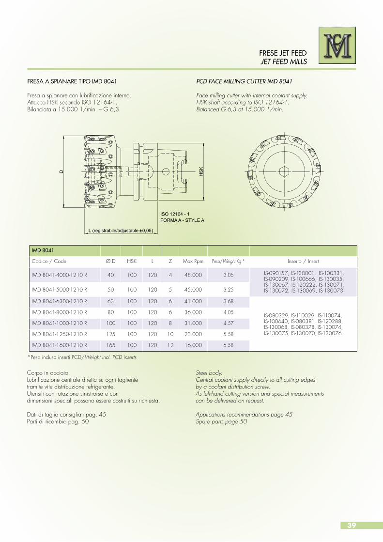
FRESA A SPIANARE TIPO IMD 8041
Fresa a spianare con lubrificazione interna.Attacco HSK secondo ISO 12164-1.Bilanciata a 15.000 1/min. – G 6,3.
PCD FACE MILLING CUTTER IMD 8041
Face milling cutter with internal coolant supply.HSK shaft according to ISO 12164-1.Balanced G 6,3 at 15.000 1/min.
ISO 12164 - 1FORMA A - STYLE A
D
L (registrabile/adjustable ±0,05)
HS
K
Corpo in acciaio.Lubrificazione centrale diretta su ogni taglientetramite vite distribuzione refrigerante.Utensili con rotazione sinistrorsa e con dimensioni speciali possono essere costruiti su richiesta.
Dati di taglio consigliati pag. 45Parti di ricambio pag. 50
Steel body.Central coolant supply directly to all cutting edgesby a coolant distribution screw.As left-hand cutting version and special measurementscan be delivered on request.
Applications recommendations page 45Spare parts page 50
FRESE JET FEED JET FEED MILLS
IMD 8041
Codice / Code Ø D HSK L Z Max Rpm Peso/Weight Kg.* Inserto / Insert
IMD 8041-4000-1210 R 40 100 120 4 48.000 3.05 IS-090157, IS-130001, IS-100331,IS-090209, IS-100666, IS-130035,IS-130067, IS-120222, IS-130071,IS-130072, IS-130069, IS-130073IMD 8041-5000-1210 R 50 100 120 5 45.000 3.25
IMD 8041-6300-1210 R 63 100 120 6 41.000 3.68
IS-080329, IS-110029, IS-110074,IS-100640, IS-080381, IS-120288,IS-130068, IS-080378, IS-130074,IS-130075, IS-130070, IS-130076
IMD 8041-8000-1210 R 80 100 120 6 36.000 4.05
IMD 8041-1000-1210 R 100 100 120 8 31.000 4.57
IMD 8041-1250-1210 R 125 100 120 10 23.000 5.58
IMD 8041-1600-1210 R 165 100 120 12 16.000 6.58
*Peso incluso inserti PCD/Weight incl. PCD inserts
40
FRESE JET FEEDJET FEED MILLS
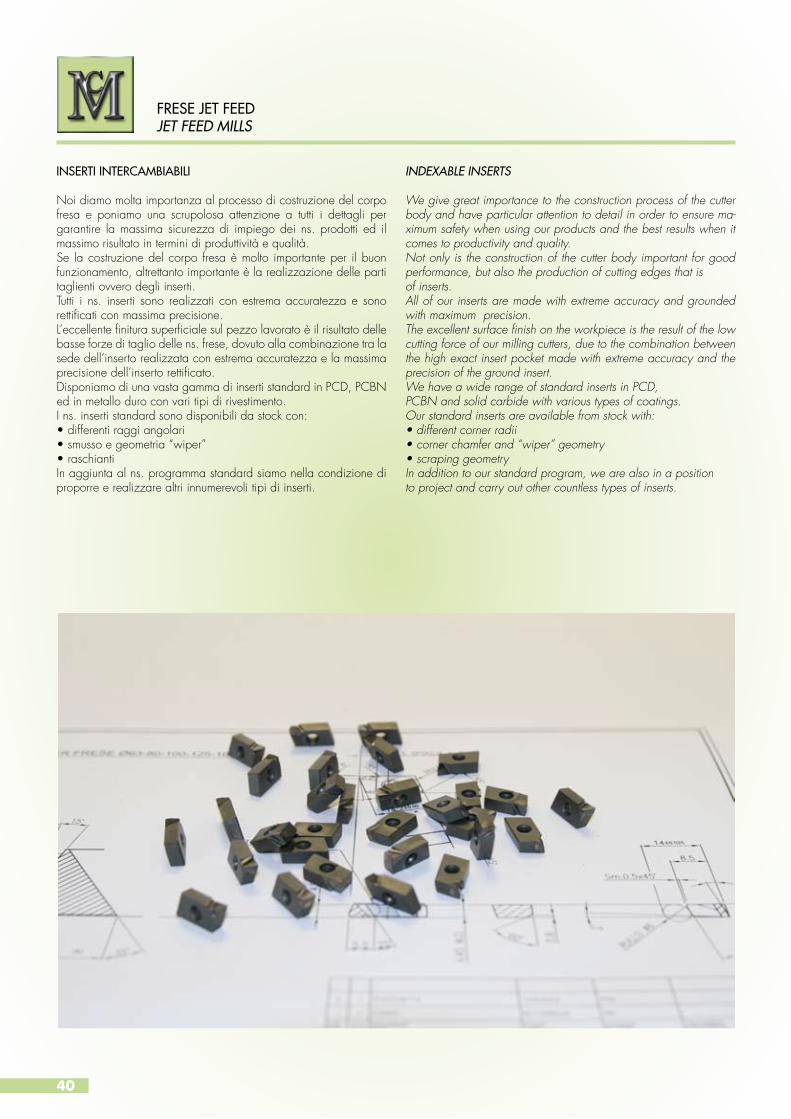
We give great importance to the construction process of the cutter body and have particular attention to detail in order to ensure ma-ximum safety when using our products and the best results when it comes to productivity and quality. Not only is the construction of the cutter body important for good performance, but also the production of cutting edges that isof inserts.All of our inserts are made with extreme accuracy and grounded with maximum precision. The excellent surface finish on the workpiece is the result of the low cutting force of our milling cutters, due to the combination between the high exact insert pocket made with extreme accuracy and the precision of the ground insert. We have a wide range of standard inserts in PCD, PCBN and solid carbide with various types of coatings. Our standard inserts are available from stock with:• different corner radii • corner chamfer and “wiper” geometry• scraping geometry In addition to our standard program, we are also in a positionto project and carry out other countless types of inserts.
Noi diamo molta importanza al processo di costruzione del corpo fresa e poniamo una scrupolosa attenzione a tutti i dettagli per garantire la massima sicurezza di impiego dei ns. prodotti ed il massimo risultato in termini di produttività e qualità.Se la costruzione del corpo fresa è molto importante per il buon funzionamento, altrettanto importante è la realizzazione delle parti taglienti ovvero degli inserti.Tutti i ns. inserti sono realizzati con estrema accuratezza e sono rettificati con massima precisione.L’eccellente finitura superficiale sul pezzo lavorato è il risultato delle basse forze di taglio delle ns. frese, dovuto alla combinazione tra la sede dell’inserto realizzata con estrema accuratezza e la massima precisione dell’inserto rettificato.Disponiamo di una vasta gamma di inserti standard in PCD, PCBN ed in metallo duro con vari tipi di rivestimento.I ns. inserti standard sono disponibili da stock con:•differentiraggiangolari•smussoegeometria“wiper”•raschiantiIn aggiunta al ns. programma standard siamo nella condizione di proporre e realizzare altri innumerevoli tipi di inserti.
INDEXABLE INSERTSINSERTI INTERCAMBIABILI

41
INSERTS DESIGNATIONCHIAVE DI LETTURA DEI CODICI DEGLI INSERTI
Esempio di ordinazione
IS 080329 – 0175 – S – D10 1 2 3 4 5
1. Tipo prodotto
IS Inserto
2. Codice
080329 Disegno
3. Imbocco
4. Preparazione tagliente
5. Materiale tagliente
Ordering example
IS 080329 – 0175 – S – D10 1 2 3 4 5
1. Type of product
IS Insert
2. Code
080329 Drawing
3. Lead
4. Cutting edge preparation
5. Cutting material
Imbocco Smusso Raggio
0175 0,1 x 75°
0190 0,1 x 90°
0200 0,2
0400 0,4
0800 0,8
0845 0,8 x 45°
S Standard
X Speciale per materiali non ferrosi
Y Speciale per materiali non ferrosi
Z Speciale per ghisa
W Raschiante
Codice Grado
K 10 K10 - K20 non rivestito
T 10 K10 - K20 rivestito TiN
W 10 K10 - K20 rivestito TiAlN
W 20 K10 - K20 rivestito TiAlN
T B 2 K10 - K20 rivestito TiB2
CCD K10 - K20 rivestito Diamante
D 10 PCD grani 10 micron
D 25 PCD grani 25 micron
D 30 PCD micro grani
B 10 CBN
B 20 CBN elevato contenuto di CBN
Code Grade
K 10 K10 - K20 uncoated
T 10 K10 - K20 coated TiN
W 10 K10 - K20 coated TiAlN
W 20 K10 - K20 coated TiAlN
T B 2 K10 - K20 coated TiB2
CCD K10 - K20 coated Diamond
D 10 PCD 10 micron gran size
D 25 PCD 25 micron gran size
D 30 PCD mixed-grain
B 10 CBN
B 20 CBN high CBN content
S Standard
X Special for non ferrous material
Y Special for non ferrous material
Z Special for cast iron
W Scraping
Lead Chamfer Radius
0175 0,1 x 75°
0190 0,1 x 90°
0200 0,2
0400 0,4
0800 0,8
0845 0,8 x 45°
FRESE JET FEED JET FEED MILLS

42
FRESE JET FEEDJET FEED MILLS
INDEXABLE INSERTS FOR MILLING CUTTERSIMD 4040-4041 - IMD 6040-6041 - IMD 5040-5041IMD 3040-3041 - IMD 8040-8041
INSERTI INTERCAMBIABILI PER FRESE IMD 4040-4041 - IMD 6040-6041 - IMD 5040-5041IMD 3040-3041 - IMD 8040-8041
H
L
R
PE
E
Inserti in Metallo Duro Carbide Inserts
•A richiesta in tempi brevi. •In short time available.
Metallo duroCarbide
Non Rivestito
Uncoated
RivestitoCoated
RivestitoCoated
RivestitoCoated
Rivestito Coated
Rivestito Coated
Codice / Code L H R E PE K10 T10 W10 W20 TB2 CCD
IS 120222 - 0175 S 13 5 0,1x75° 1,8 • • • • • •
IS 120222 - 0190 S 13 4,5 0,1x90° 1,8 • • • • • •
IS 120222 - 1000 W 13 5 raschiante / scraping • • • • • •
IS 130071 - 0400 S 13 4,5 0,4 • • • • • •
IS 130072 - 0800 S 13 4,5 0,8 • • • • • •
IS 130069 - 0800 S 13 4,5 0,8 • • • • • •
IS 130073 - 2000 W 13 5 raschiante / scraping • • • • • •
IS 080378 - 0175 S 14,2 5 0,1x75° 1,8 • • • • • •
IS 080378 - 0190 S 14,2 4,5 0,1x90° 1,8 • • • • • •
IS 080378 - 1000 W 14,2 5 raschiante / scraping • • • • • •
IS 130074 - 0400 S 14,2 4,5 0,4 • • • • • •
IS 130075 - 0800 S 14,2 4,5 0,8 • • • • • •
IS 130070 - 0800 S 14,2 4,5 0,8 • • • • • •
IS 130076 - 2000 W 14,2 5 raschiante / scraping • • • • • •
43
FRESE JET FEED JET FEED MILLS
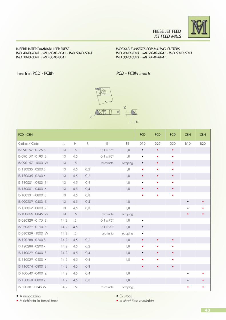
INDEXABLE INSERTS FOR MILLING CUTTERSIMD 4040-4041 - IMD 6040-6041 - IMD 5040-5041IMD 3040-3041 - IMD 8040-8041
INSERTI INTERCAMBIABILI PER FRESEIMD 4040-4041 - IMD 6040-6041 - IMD 5040-5041IMD 3040-3041 - IMD 8040-8041
Inserti in PCD - PCBN PCD - PCBN inserts
•Amagazzino• A richiesta in tempi brevi
• Ex stock• In short time available
H
L
EP
E
R
PCD - CBN PCD PCD PCD CBN CBN
Codice / Code L H R E PE D10 D25 D30 B10 B20
IS 090157 - 0175 S 13 5 0,1 x 75° 1,8 • • •
IS 090157 - 0190 S 13 4,5 0,1 x 90° 1,8 • • •
IS 090157 - 1000 W 13 5 raschiante scraping • • •
IS 130035 - 0200 S 13 4,5 0,2 1,8 • • •
IS 130035 - 0200 X 13 4,5 0,2 1,8 • • •
IS 130001 - 0400 S 13 4,5 0,4 1,8 • • •
IS 130001 - 0400 X 13 4,5 0,4 1,8 • • •
IS 100331 - 0800 S 13 4,5 0,8 • • •
IS 090209 - 0400 Z 13 4,5 0,4 1,8 • •
IS 130067 - 0800 Z 13 4,5 0,8 1,8 • •
IS 100666 - 0845 W 13 5 raschiante scraping • •
IS 080329 - 0175 S 14,2 5 0,1 x 75° 1,8 •
IS 080329 - 0190 S 14,2 4,5 0,1 x 90° 1,8 •
IS 080329 - 1000 W 14,2 5 raschiante scraping •
IS 120288 - 0200 S 14,2 4,5 0,2 1,8 • • •
IS 120288 - 0200 X 14,2 4,5 0,2 1,8 • • •
IS 110029 - 0400 S 14,2 4,5 0,4 1,8 • • •
IS 110029 - 0400 X 14,2 4,5 0,4 1,8 • • •
IS 110074 - 0800 S 14,2 4,5 0,8 • • •
IS 100640 - 0400 Z 14,2 4,5 0,4 1,8 • •
IS 130068 - 0800 Z 14,2 4,5 0,8 1,8 • •
IS 080381- 0845 W 14,2 5 raschiante scraping • •
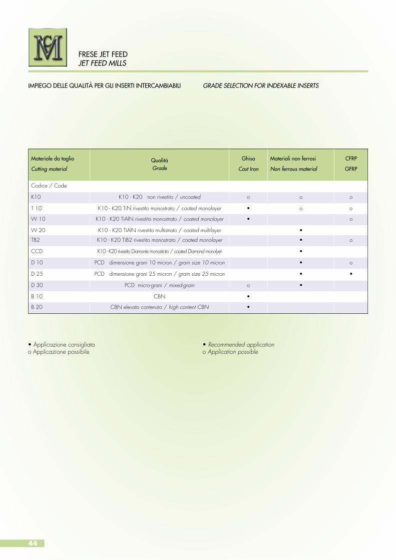
Materiale da taglio Cutting material
QualitàGrade
Ghisa
Cast Iron
Materiali non ferrosi Non ferrous material
CFRP
GFRP
Codice / Code
K10 K10 - K20 non rivestito / uncoated o o o
T 10 K10 - K20 TiN rivestito monostrato / coated monolayer • o o
W 10 K10 - K20 TiAlN rivestito monostrato / coated monolayer • o
W 20 K10 - K20 TiAlN rivestito multistrato / coated multilayer •
TB2 K10 - K20 TiB2 rivestito monostrato / coated monolayer • o
CCD K10 - K20 rivestito Diamante monostrato / coated Diamond monolyer •
D 10 PCD dimensione grani 10 micron / grain size 10 micron • o
D 25 PCD dimensione grani 25 micron / grain size 25 micron • •
D 30 PCD micro-grani / mixed-grain o •
B 10 CBN •
B 20 CBN elevato contenuto / high content CBN •
44
FRESE JET FEEDJET FEED MILLS
GRADE SELECTION FOR INDEXABLE INSERTSIMPIEGO DELLE QUALITÀ PER GLI INSERTI INTERCAMBIABILI
•Applicazioneconsigliatao Applicazione possibile
• Recommended applicationo Application possible

45
FRESE JET FEED JET FEED MILLS
Dati di taglio consigliati Cutting data recommendations
TECHNICAL HINTS FOR MILLING CUTTERSIMD 4040-4041 - IMD 6040-6041 - IMD 5040-5041IMD 3040-3041 - IMD 8040-8041
NOTE TECNICHE PER FRESEIMD 4040-4041 - IMD 6040-6041 - IMD 5040-5041IMD 3040-3041 - IMD 8040-8041
I dati di taglio indicati nella tabella sono indicativi e dipendono dalla stabilità della macchina e dal fissaggio stabile del pezzoda lavorare.
The cutting data recommendations in the table are guide values and depend to a high degree on the stability of the machine, fixture and workpiece.
Materiale da lavorare
Workpiece material
Velocità di taglio
Cutting Speedfz
(mm)K10 T10 W10 W20 TB2 CCD D10
D20 D30
B10B20
Al < 4% Si 200-800 200-1000 200-1200 200-1500 500-5000 500-5000 0,05 - 0,25
Al 4-9 % Si 200-600 200-1000 200-1200 200-1200 500-4000 500-4000 0,05 - 0,25
Al > 10% Si 200-600 200-800 200-1000 200-1200 200-3500 200-3500 0,05 - 0,25
Leghe di magnesio Magnesium alloy 200-800 200-1000 200-1200 200-1500 300-5000 300-5000 0,05 - 0,30
Leghe di ottoneBrass alloy 200-300 200-400 200-800 200-1000 300-5000 300-5000 0,05 - 0,25
Leghe di rameCopper alloy 200-300 200-400 200-800 200-1000 300-6000 300-6000 0,05 - 0,25
CFRP 100-200 100-250 100-500 100-400 200-650 200-650 0,05 - 0,15
GFRP 100-200 100-250 100-500 100-400 200-800 200-800 0,05 - 0,20
GrafiteGraphite 100-200 100-250 100-400 200-2000 200-2000 0,05 - 0,20
GhisaCast iron 80-150 80-200 140-250 200-300 400-800 0,05 - 0,25
vc (m/min)

46
FRESE JET FEEDJET FEED MILLS
MACHINING INSTRUCTIONSINDICAZIONI PER LA LAVORAZIONE
CONCORDANZA
DISCORDANZA
ACCORDANCE
DISCORDANCE
Da preferire la fresatura in concordanza se ci sono le condizioni di stabilità e di potenza della macchina.
Posizione fra pezzo e fresa consigliata.
ØD della fresa per spianatura consigliato in funzione della larghezza ae: ØD = + 20/30% di ae.
Accordance milling is preferable if conditions of stability and machine power are present.
Reccomended position between workpiece and milling cutter.
Diameter (ØD) of the flattening milling cutter that is reccomended according to the width ae: diameter (ØD) = +20-30% of ae.
Vf
Vc
Vf
Vc
ØDae
Vf
Vc

47
FRESE JET FEED JET FEED MILLS
GUIDA ALLE FORMULE E SIGLE / GENERAL ACRONIMS AND FORMULAS
ØD Diametro della fresa [mm] Milling diameter
ap Profondità di taglio [mm] Axial depth of cut
ae Larghezza di taglio [mm] Width of cut
vc Velocità di taglio [m/min] Cutting speed
n Numero di giri [min-1] Number of revolutions
z Numero di taglienti Number of teeth
fz Avanzamento per tagliente [mm] Feed rate per tooth
vf Velocità di avanzamento [mm/min] Feed rate
Lm Lunghezza di fresatura [mm] Machining lenght
Tc Tempo di lavoro [min] Machining time
Q Volume truciolo [cm3/min] Rate of metal removal
kc Forza di taglio specifica [N/mm2] Specific cutting force
P Potenza necessaria [kW] Necessary power
η Fattore di efficienza Efficiency factor
Velocità di taglio vc = øD . π . nCutting speed 1000
Numero di giri n = vc . 1000Number of revolutions øD . π Velocità di avanzamento vf = fz . n . z Feed rate
Avanzamento per tagliente fz = vf
Speed rate per tooth n . z
Tempo di lavoro Tc = Lm
Machining time vf
Volume truciolo Q = ap . ae . vf
Rate of metal removal 1000
Potenza richiesta P = ap . ae . vf . kc
Required (drive power) 60 . 106 . η
AbbreviazioniAbbreviations
DescrizioneDescription
FormuleFormula

48
FRESE JET FEEDJET FEED MILLS
SCHEMA DI MONTAGGIO PER FRESE IMD 4040-4041IMD 6040-6041 IMD 5040-5041 IMD 3040-3041IMD 8040-8041
Istruzioni di registrazione
Coppia di serraggio per vite bloccaggio inserto
Fase AAvvitare la vite di registrazione (3) fino ad arrivare a battuta.
Fase BMontare gli inserti (1).Fissare gli inserti agendo sulla vite di fissaggio (2) con una coppiadi serraggio di 2,5 Nm.
Fase CPresettare gli inserti a quota teorica LR con la vite di registrazione (3). Regolazione assiale max.=0,1 mm.
Fase DAllineare gli inserti alla stessa altezzaagendo sulla vite di registrazione (3)del cuneo con un run-out assialedi 0,005 mm.
Coppia di serraggio Torx
2,5 (Nm) Tx 10IP
49
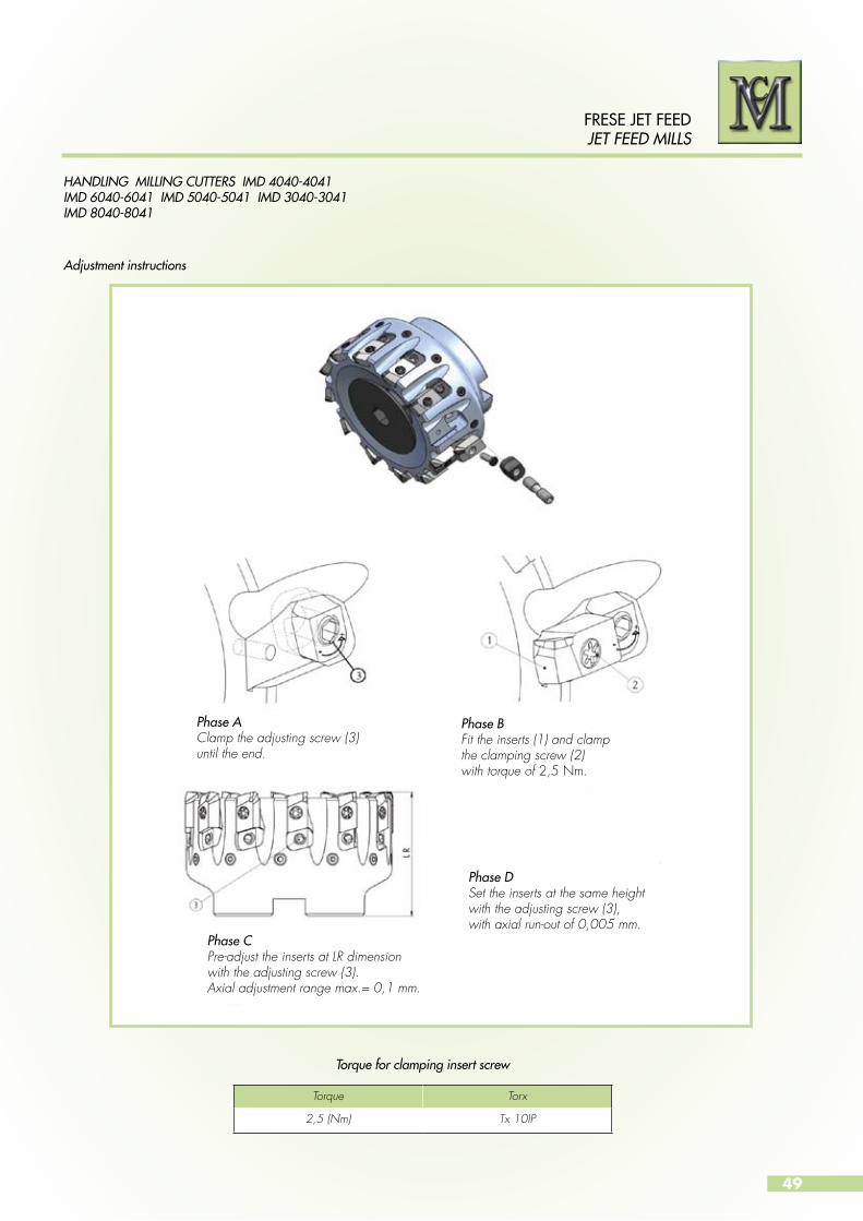
HANDLING MILLING CUTTERS IMD 4040-4041IMD 6040-6041 IMD 5040-5041 IMD 3040-3041IMD 8040-8041
FRESE JET FEED JET FEED MILLS
Torque for clamping insert screw
Adjustment instructions
Phase AClamp the adjusting screw (3)until the end.
Phase BFit the inserts (1) and clampthe clamping screw (2)with torque of 2,5 Nm.
Phase CPre-adjust the inserts at LR dimensionwith the adjusting screw (3). Axial adjustment range max.= 0,1 mm.
Phase DSet the inserts at the same height with the adjusting screw (3), with axial run-out of 0,005 mm.
Torque Torx
2,5 (Nm) Tx 10IP

50
FRESE JET FEEDJET FEED MILLS
RICAMBI PER IMD 4040-4041, IMD 6040-6041, IMD 5040-5041, IMD 3040-3041, IMD 8040-8041.
SPARE PARTS FOR IMD 4040-4041, IMD 6040-6041,IMD 5040-5041, IMD 3040-3041, IMD 8040-8041.
Descrizione
Description
Codice ricambi
Spare part code
Frese
Milling cuttersDiametro fresa
Cutterdiameter
Dimension
DimensionsIMD 4040IMD 4041
IMD 6040IMD 6041
IMD 5040IMD 5041
IMD 3040IMD 3041
IMD 8040IMD 8041
Vite distribuzione refrigeranteCoolant distribution screw
TAP 040-00 • • 40
Vite distribuzione refrigerante Coolant distribution screw
TAP 050-00 • • 50
Vite distribuzione refrigeranteCoolant distribution screw
TAP 063-00 • • 63
Vite distribuzione refrigeranteCoolant distribution screw
TAP 080-10 • • 80
Vite distribuzione refrigeranteCoolant distribution screw
TAP 100-00 • • 100
Vite distribuzione refrigeranteCoolant distribution screw
TAP 125-00 • • 125
Coperchio distribuzione refrigeranteCoolant distribution cap
TAP 160-00 • 160
Coperchio distribuzione refrigeranteCoolant distribution cap
TAP 200-00 • 200
Coperchio distribuzione refrigeranteCoolant distribution cap
TAP 250-00 • 250
Coperchio distribuzione refrigeranteCoolant distribution cap
TAP 315-00 • 315
Cuneo regolazione Adjusting wedge
RX 080-392 • • • • • 32-315
Vite cuneo di regolazioneAdjusting wedge screw
VX 05-13 • • • • 32-50 M5x0,5LH/RHx13
Vite cuneo di regolazioneAdjusting wedge screw
VX 05-16 • • • 63-315 M5x0,5LH/RHx16
Vite insertoInsert screw
TX 03-09 • • • • • 32-315 M3x9 (Torx)
Vite bilanciatura Balancing screw
EX 05-10 • • • • 32-50 M5x10
Vite bilanciaturaBalancing screw
EX 06-10 • • 63-125 M6x10
Vite bilanciaturaBalancing screw
EX 12x1-16 • 160-315 M12x1 L=16
Vite coperchio distribuzione refrigeranteCoolant distribution cap screw
SX 04-20 • 160-315 M4X20
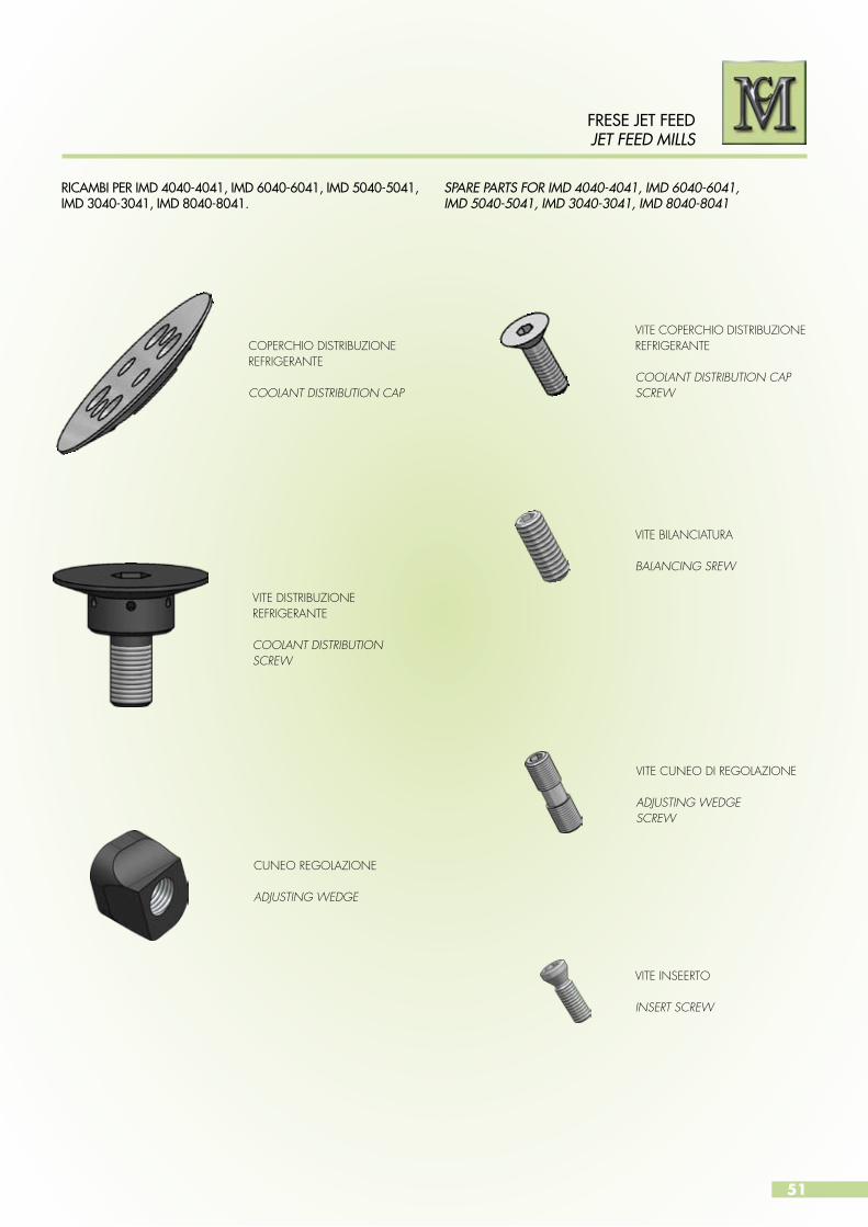
51
FRESE JET FEED JET FEED MILLS
VITE COPERCHIO DISTRIBUZIONE REFRIGERANTE
COOLANT DISTRIBUTION CAP SCREW
RICAMBI PER IMD 4040-4041, IMD 6040-6041, IMD 5040-5041, IMD 3040-3041, IMD 8040-8041.
SPARE PARTS FOR IMD 4040-4041, IMD 6040-6041,IMD 5040-5041, IMD 3040-3041, IMD 8040-8041
VITE BILANCIATURA
BALANCING SREW
VITE CUNEO DI REGOLAZIONE
ADJUSTING WEDGESCREW
VITE INSEERTO
INSERT SCREW
VITE DISTRIBUZIONE REFRIGERANTE
COOLANT DISTRIBUTION SCREW
CUNEO REGOLAZIONE
ADJUSTING WEDGE
COPERCHIO DISTRIBUZIONE REFRIGERANTE
COOLANT DISTRIBUTION CAP
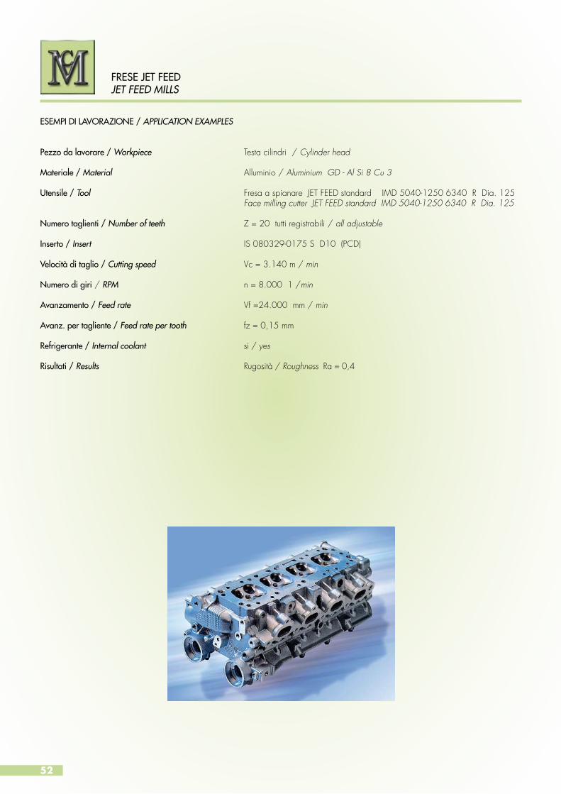
52
FRESE JET FEEDJET FEED MILLS
ESEMPI DI LAVORAZIONE / APPLICATION EXAMPLES
Pezzo da lavorare / Workpiece Testa cilindri / Cylinder head
Materiale / Material Alluminio / Aluminium GD - Al Si 8 Cu 3
Utensile / Tool Fresa a spianare JET FEED standard IMD 5040-1250 6340 R Dia. 125 Face milling cutter JET FEED standard IMD 5040-1250 6340 R Dia. 125
Numero taglienti / Number of teeth Z = 20 tutti registrabili / all adjustable
Inserto / Insert IS 080329-0175 S D10 (PCD)
Velocità di taglio / Cutting speed Vc = 3.140 m / min
Numero di giri / RPM n = 8.000 1 /min
Avanzamento / Feed rate Vf =24.000 mm / min
Avanz. per tagliente / Feed rate per tooth fz = 0,15 mm
Refrigerante / Internal coolant si / yes
Risultati / Results Rugosità / Roughness Ra = 0,4

53
FRESE JET FEED JET FEED MILLS
ESEMPI DI LAVORAZIONE / APPLICATION EXAMPLES
Pezzo da lavorare / Workpiece Blocco motore / Engine block
Materiale / Material Alluminio / Aluminium GD - Al Si 11
Utensile / Tool Fresa a spianare JET FEED standard IMD 5040-1000 5032 R Dia. 100 Face milling cutter JET FEED standard IMD 5040-1000 5032 R Dia. 100
Numero taglienti / Number of teeth Z = 16 tutti registrabili / all adjustable
Inserto / Insert IS 080329-0175 S D10 (PCD)
Velocità di taglio / Cutting speed Vc = 2.355 m/min
Numero di giri / RPM n = 7.500 1 /min (max. numero di giri del mandrino / max. number of spindle revolutions)
Avanzamento / Feed rate Vf =19.200 mm. / min
Avanz. per tagliente / Feed rate per tooth fz = 0,16 mm
Refrigerante / Internal coolant si / yes
Risultati / Results Rugosità / Roughness Ra = 2 - 4
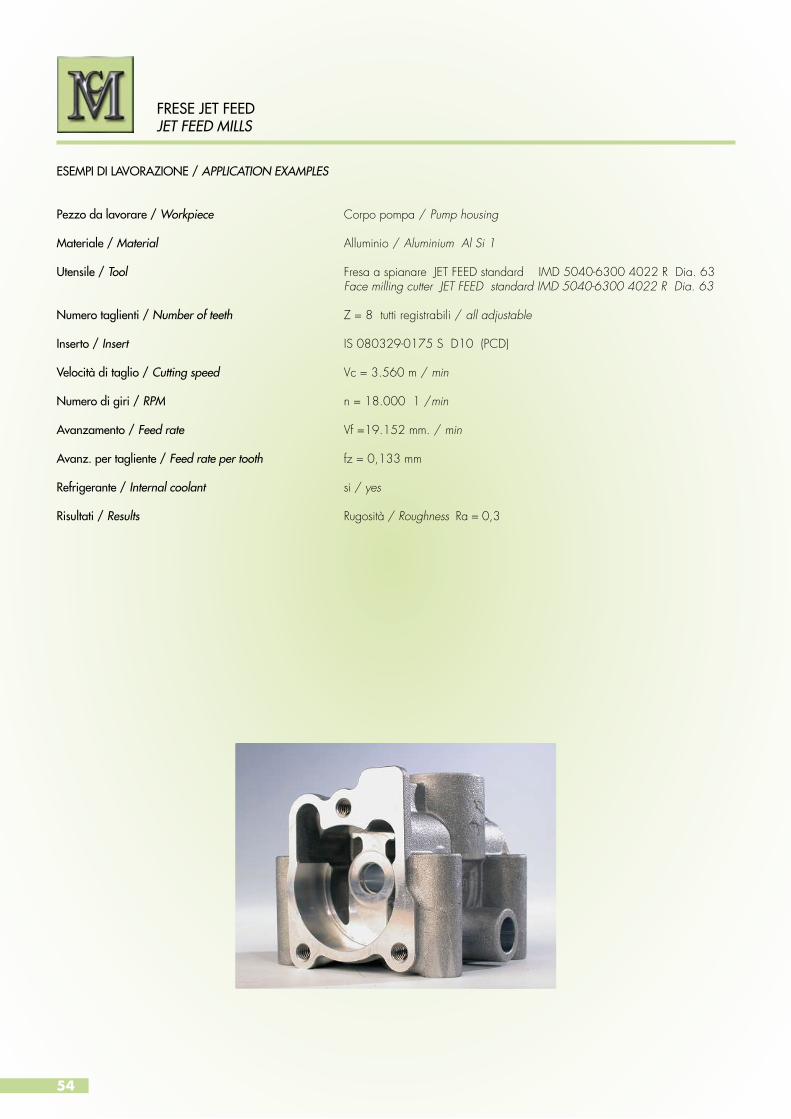
54
FRESE JET FEEDJET FEED MILLS
ESEMPI DI LAVORAZIONE / APPLICATION EXAMPLES
Pezzo da lavorare / Workpiece Corpo pompa / Pump housing
Materiale / Material Alluminio / Aluminium Al Si 1
Utensile / Tool Fresa a spianare JET FEED standard IMD 5040-6300 4022 R Dia. 63 Face milling cutter JET FEED standard IMD 5040-6300 4022 R Dia. 63
Numero taglienti / Number of teeth Z = 8 tutti registrabili / all adjustable
Inserto / Insert IS 080329-0175 S D10 (PCD)
Velocità di taglio / Cutting speed Vc = 3.560 m / min
Numero di giri / RPM n = 18.000 1 /min
Avanzamento / Feed rate Vf =19.152 mm. / min
Avanz. per tagliente / Feed rate per tooth fz = 0,133 mm
Refrigerante / Internal coolant si / yes
Risultati / Results Rugosità / Roughness Ra = 0,3
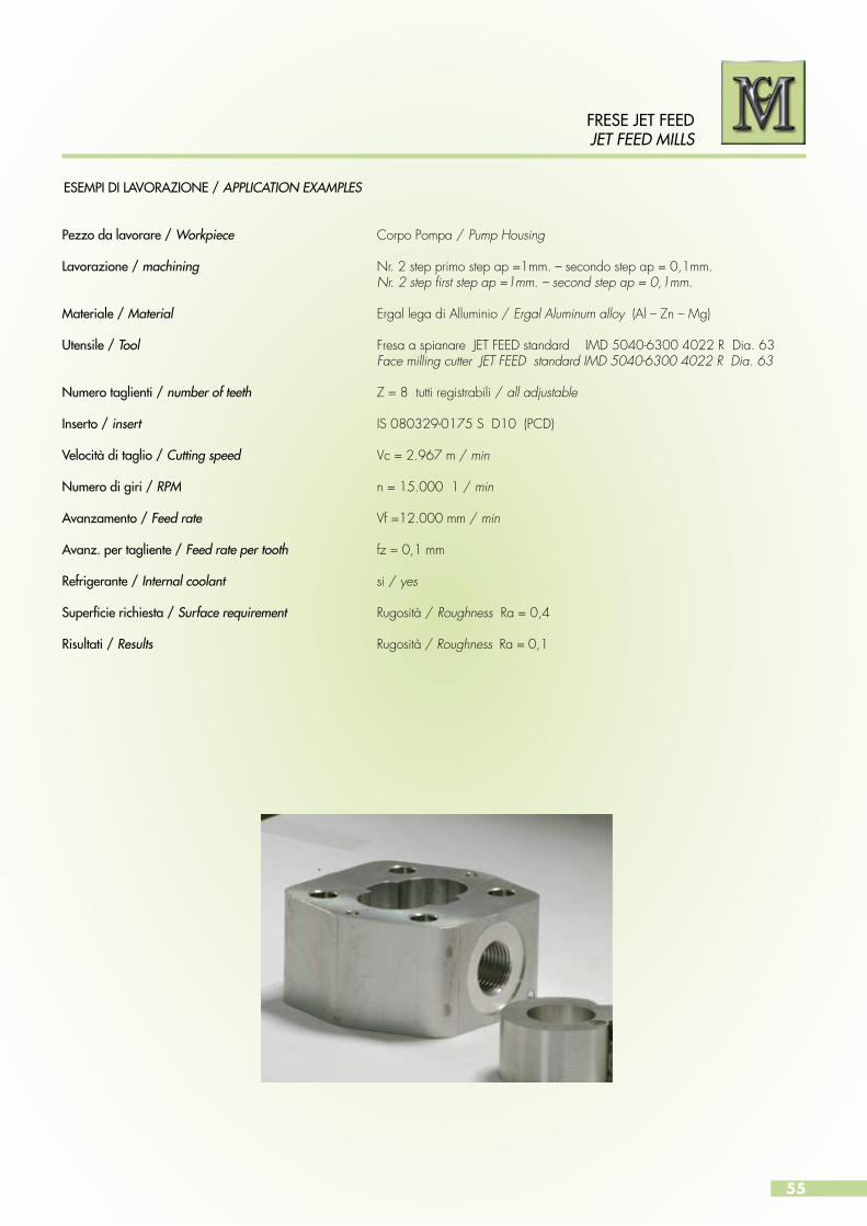
55
FRESE JET FEED JET FEED MILLS
ESEMPI DI LAVORAZIONE / APPLICATION EXAMPLES
Pezzo da lavorare / Workpiece Corpo Pompa / Pump Housing
Lavorazione / machining Nr. 2 step primo step ap =1mm. – secondo step ap = 0,1mm. Nr. 2 step first step ap =1mm. – second step ap = 0,1mm.
Materiale / Material Ergal lega di Alluminio / Ergal Aluminum alloy (Al – Zn – Mg)
Utensile / Tool Fresa a spianare JET FEED standard IMD 5040-6300 4022 R Dia. 63 Face milling cutter JET FEED standard IMD 5040-6300 4022 R Dia. 63
Numero taglienti / number of teeth Z = 8 tutti registrabili / all adjustable
Inserto / insert IS 080329-0175 S D10 (PCD)
Velocità di taglio / Cutting speed Vc = 2.967 m / min
Numero di giri / RPM n = 15.000 1 / min
Avanzamento / Feed rate Vf =12.000 mm / min
Avanz. per tagliente / Feed rate per tooth fz = 0,1 mm
Refrigerante / Internal coolant si / yes
Superficie richiesta / Surface requirement Rugosità / Roughness Ra = 0,4
Risultati / Results Rugosità / Roughness Ra = 0,1
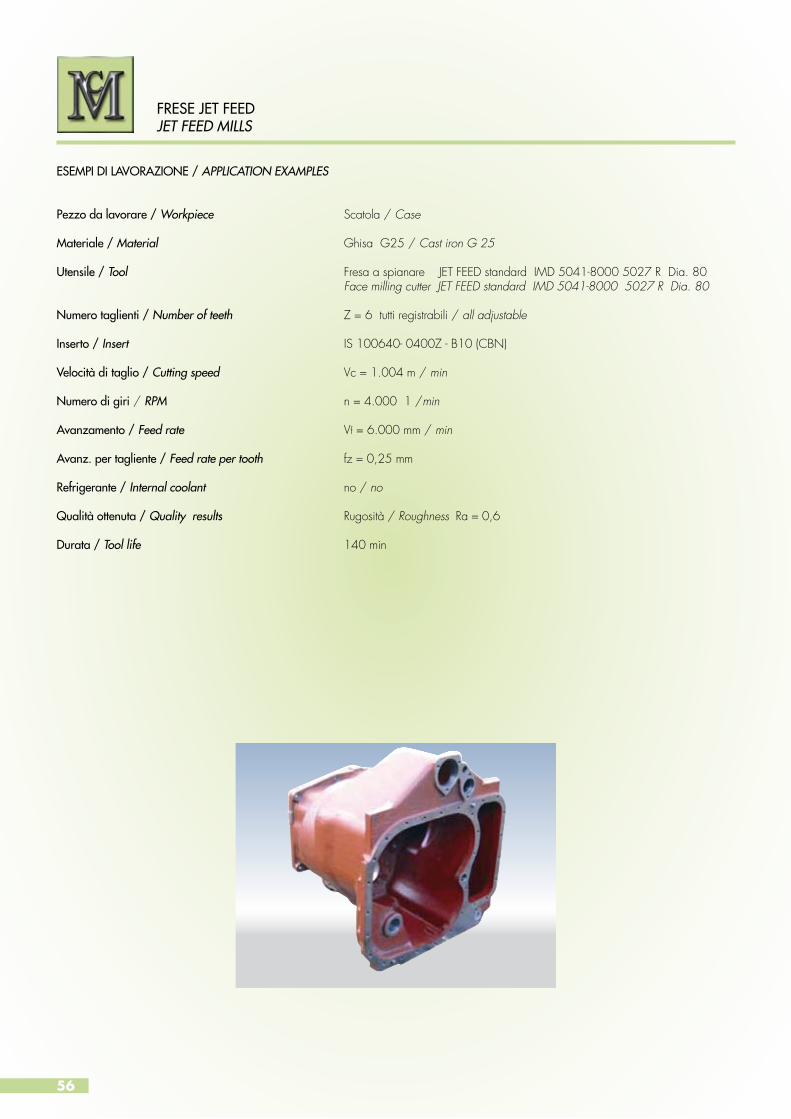
56
FRESE JET FEEDJET FEED MILLS
ESEMPI DI LAVORAZIONE / APPLICATION EXAMPLES
Pezzo da lavorare / Workpiece Scatola / Case
Materiale / Material Ghisa G25 / Cast iron G 25
Utensile / Tool Fresa a spianare JET FEED standard IMD 5041-8000 5027 R Dia. 80 Face milling cutter JET FEED standard IMD 5041-8000 5027 R Dia. 80
Numero taglienti / Number of teeth Z = 6 tutti registrabili / all adjustable
Inserto / Insert IS 100640- 0400Z - B10 (CBN)
Velocità di taglio / Cutting speed Vc = 1.004 m / min
Numero di giri / RPM n = 4.000 1 /min
Avanzamento / Feed rate Vf = 6.000 mm / min
Avanz. per tagliente / Feed rate per tooth fz = 0,25 mm
Refrigerante / Internal coolant no / no
Qualità ottenuta / Quality results Rugosità / Roughness Ra = 0,6
Durata / Tool life 140 min

57
FRESE JET FEED JET FEED MILLS
ESEMPI DI LAVORAZIONE / APPLICATION EXAMPLES
Pezzo da lavorare / Workpiece Scatola / Case
Materiale / Material Ghisa GS 400 / Cast iron GS 400
Utensile / Tool Fresa a spianare JET FEED standard IMD 5041-8000 5027 R Dia. 80 Face milling cutter JET FEED standard IMD 5041-8000 5027 R Dia. 80
Numero taglienti / Number of teeth Z = 6 tutti registrabili / all adjustable
Inserto / Insert IS 100640- 0400Z – B20 (CBN)
Velocità di taglio / Cutting speed Vc = 753,6 m / min
Numero di giri / RPM n = 3.000 1 /min
Avanzamento / Feed rate Vf = 3.420 mm / min
Avanz. per tagliente / Feed rate per tooth fz = 0,19 mm
Refrigerante / Internal coolant no / no
Superficie richiesta / surface requirement Rugosità / Roughness Ra = 1,2
Qualità ottenuta / Quality results Rugosità / Roughness Ra = 0,4 - 0,8
Durata / Tool life 120 min
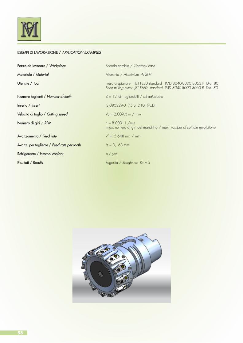
58
ESEMPI DI LAVORAZIONE / APPLICATION EXAMPLES
Pezzo da lavorare / Workpiece Scatola cambio / Gearbox case
Materiale / Material Alluminio / Aluminium Al Si 9
Utensile / Tool Fresa a spianare JET FEED standard IMD 8040-8000 8063 R Dia. 80 Face milling cutter JET FEED standard IMD 8040-8000 8063 R Dia. 80
Numero taglienti / Number of teeth Z = 12 tutti registrabili / all adjustable
Inserto / Insert IS 080329-0175 S D10 (PCD)
Velocità di taglio / Cutting speed Vc = 2.009,6 m / min
Numero di giri / RPM n = 8.000 1 /min (max. numero di giri del mandrino / max. number of spindle revolutions)
Avanzamento / Feed rate Vf =15.648 mm / min
Avanz. per tagliente / Feed rate per tooth fz = 0,163 mm
Refrigerante / Internal coolant si / yes
Risultati / Results Rugosità / Roughness Rz = 5

59
ESEMPI DI LAVORAZIONE / APPLICATION EXAMPLES
Pezzo da lavorare / Workpiece Scatola trasmissione / Trasmission housing
Materiale / Material Alluminio / Aluminium GD-Al Si 9Cu3
Utensile / Tool Fresa a spianare JET FEED standard IMD 5040-8000 5027 R Dia. 80 Face milling cutter JET FEED standard IMD 5040-8000 5027 R Dia. 80
Numero taglienti / Number of teeth Z = 12 tutti registrabili / all adjustable
Inserto / Insert IS 080329-0175 S D10 (PCD)
Velocità di taglio / Cutting speed Vc = 3.768 m / min
Numero di giri / RPM n = 15.000 1 /min (max. numero di giri del mandrino / max. number of spindle revolutions)
Avanzamento / Feed rate Vf = 9.000 mm / min
Avanz. per tagliente / Feed rate per tooth fz = 0,05 mm
Refrigerante / Internal coolant si / yes
Risultati / Results Rugosità / Roughness Rz = 5
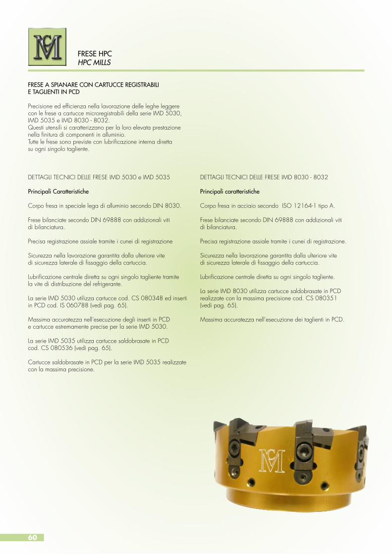
60
FRESE HPCHPC MILLS
Precisione ed efficienza nella lavorazione delle leghe leggerecon le frese a cartucce microregistrabili della serie IMD 5030,IMD 5035 e IMD 8030 - 8032.Questi utensili si caratterizzano per la loro elevata prestazionenella finitura di componenti in alluminio.Tutte le frese sono previste con lubrificazione interna direttasu ogni singolo tagliente.
FRESE A SPIANARE CON CARTUCCE REGISTRABILIE TAGLIENTI IN PCD
DETTAGLI TECNICI DELLE FRESE IMD 5030 e IMD 5035
Principali Caratteristiche
Corpo fresa in speciale lega di alluminio secondo DIN 8030.
Frese bilanciate secondo DIN 69888 con addizionali vitidi bilanciatura.
Precisa registrazione assiale tramite i cunei di registrazione
Sicurezza nella lavorazione garantita dalla ulteriore vitedi sicurezza laterale di fissaggio della cartuccia.
Lubrificazione centrale diretta su ogni singolo tagliente tramitela vite di distribuzione del refrigerante.
La serie IMD 5030 utilizza cartucce cod. CS 080348 ed inserti in PCD cod. IS 060788 (vedi pag. 65).
Massima accuratezza nell’esecuzione degli inserti in PCDe cartucce estremamente precise per la serie IMD 5030.
La serie IMD 5035 utilizza cartucce saldobrasate in PCDcod. CS 080536 (vedi pag. 65).
Cartucce saldobrasate in PCD per la serie IMD 5035 realizzate con la massima precisione.
DETTAGLI TECNICI DELLE FRESE IMD 8030 - 8032
Principali caratteristiche
Corpo fresa in acciaio secondo ISO 12164-1 tipo A.
Frese bilanciate secondo DIN 69888 con addizionali vitidi bilanciatura.
Precisa registrazione assiale tramite i cunei di registrazione.
Sicurezza nella lavorazione garantita dalla ulteriore vitedi sicurezza laterale di fissaggio della cartuccia.
Lubrificazione centrale diretta su ogni singolo tagliente.
La serie IMD 8030 utilizza cartucce saldobrasate in PCD realizzate con la massima precisione cod. CS 080351(vedi pag. 65).
Massima accuratezza nell’esecuzione dei taglienti in PCD.

61
FRESE HPCHPC MILLS
Precision and efficiency in the in the machining of light alloys by milling cutters with micro-adjustable cartridges in the IMD 5030, IMD 5035, IMD 8030 - 8032 series.These tools are characterized by their high performancein the finishing of aluminum components. All mills are provided with central coolant supply directly to all cutting edges.
MILLING CUTTERS WITH INDEXABLE CARTRIDGESAND PCD CUTTING EDGES
TECHNICAL SPECIFICATIONS FOR MILLS IMD 5030 and IMD 5035
Main features
Milling cutter body in special aluminium alloy accordingto DIN 8030.
Balanced milling cutters according to DIN 69888 with balancing screws.
Precise axial indexing through wedge indexing.
Safe machining guaranteed by securing the side screw cartridge attachment.
Direct central lubrication to each individual cutter throughthe refrigerant screw distribution.
The IMD 5030 series employs code CS 080348 cartridgesand PCD inserts IS 060788 (see page 65).
Superior accuracy in the execution of PCD cutting edges.
Extremely accurate cartridges and PCD inserts for the seriesIMD 5030.
The IMD 5035 series employs brazed cartridges in PCD codeCS 080536 (see page 65).
PCD brazed cartridges for IMD 5035 series compiledwith the utmost precision.
TECHNICAL SPECIFICATIONS FOR MILLS IMD 8030 - 8032
Main features
Milling cutter body in steel according to ISO 12164-1 type A.
Balanced milling cutters according to DIN 69888 with additional balanced screws.
Precise axial indexing through wedge indexing.
Safe machining guaranteed by securing the side screw cartridge attachment.
Central coolant supply and distribution directly to eachcutting edge.
The IMD 8030 series employs PCD brazed cartridges compiled with the utmost precision code CS 080351 (see page 65).
Superior accuracy in the execution of PCD cutting edges.

62
FRESE HPCHPC MILLS
FRESA A SPIANARE TIPO IMD 5030
Fresa a spianare con lubrificazione interna.Attacco a manicotto secondo DIN 8030.Bilanciata secondo DIN 69888.
FACE MILLING CUTTER IMD 5030
Face milling cutter shaft according to DIN 8030with central coolant supply.Balanced according to DIN 69888.
D
L (registrabile/adjustable ±0.05)
d H
6
Corpo in speciale lega di alluminio.Lubrificazione centrale diretta su ogni tagliente tramitevite distribuzione refrigerante.Utensili con rotazione sinistrorsae con dimensioni speciali su richiesta.
Dati di taglio consigliati pag. 66Parti di ricambio pag. 74
Special aluminim alloy body.Central coolant supply directly to all cutting edgesby a coolant distribution screw.On request available as left-hand cutting versionand special measurements.
Applications recommendations page 66Spare parts page 74
IMD 5030
Codice / Code Ø D L2 d Z Max Rpm PesoWeight Kg
Cartuccia + Inserto in PCD Cartridge + PCD Insert
IMD 5030-6300-4822 R 63 48 22 3 25.000 0.45
CS 080348 + Inserto in PCD IS 060788 - DA / DB / DCCS 080348 + PCD Insert IS 060788 - DA / DB / DC
IMD 5030-8000-5027 R 80 50 27 5 25.000 0.7
IMD 5030-1000-5032 R 100 50 32 6 21.600 1
IMD 5030-1250-6340 R 125 63 40 8 18.500 2
IMD 5030-1600-6340 R 160 63 40 10 15.000 2.7
IMD 5030-2000-6360 R 200 63 60 12 13.500 3.7
IMD 5030-2500-6360 R 250 63 60 15 12.200 5.2
IMD 5030-3150-8060 R 315 80 60 18 9.800 12
IMD 5030-4000-8060 R 400 80 60 24 6.100 20
IMD 5030-5000-8060 R 500 80 60 30 4.900 31
*Peso incluso inserti PCD e cartucce/Weight incl. PCD inserts and cartridges

63
FRESE HPCHPC MILLS
FRESA A SPIANARE TIPO IMD 5035
Fresa a spianare con lubrificazione interna. Attacco a manicotto secondo DIN 8030.Bilanciata secondo DIN 69888.
FACE MILLING CUTTER IMD 5035
Face milling cutter with central coolant supply.Shaft according to DIN 8030.Balanced according to DIN 69888.
D
L (registrabile/adjustable ±0.05)
d H
6
Corpo in speciale lega di alluminio.Lubrificazione centrale diretta su ogni tagliente tramitevite distribuzione refrigerante.Utensili con rotazione sinistrorsae con dimensioni speciali su richiesta.
Dati di taglio consigliati pag. 66Parti di ricambio pag. 74
Special aluminim alloy body.Central coolant supply directly to all cutting edgesby a coolant distribution screw.On request available as left-hand cutting versionand special measurements.
Applications recommendations page 66Spare parts page 74
IMD 5035
Codice / Code Ø D L d Z Max Rpm Peso/Weight Kg* Cartuccia + Inserto in PCD / Cartridge + PCD Insert
IMD 5035-6300-4822 R 63 48 22 3 25.000 0.45
CS 080356-DA , CS 080356-DB , CS 080356 - DC
IMD 5035-8000-5027 R 80 50 27 5 25.000 0.7
IMD 5035-1000-5032 R 100 50 32 6 21.600 1
IMD 5035-1250-6340 R 125 63 40 8 18.500 2
IMD 5035-1600-6340 R 160 63 40 10 15.000 2.7
IMD 5035-2000-6360 R 200 63 60 12 13.500 3.7
IMD 5035-2500-6360 R 250 63 60 15 12.200 5.2
IMD 5035-3150-8060 R 315 80 60 18 9.800 12
IMD 5035-4000-8060 R 400 80 60 24 6.100 20
IMD 5035-5000-8060 R 500 80 60 30 4.900 31
*Peso incluso cartucce PCD/Weight incl. PCD cartridges
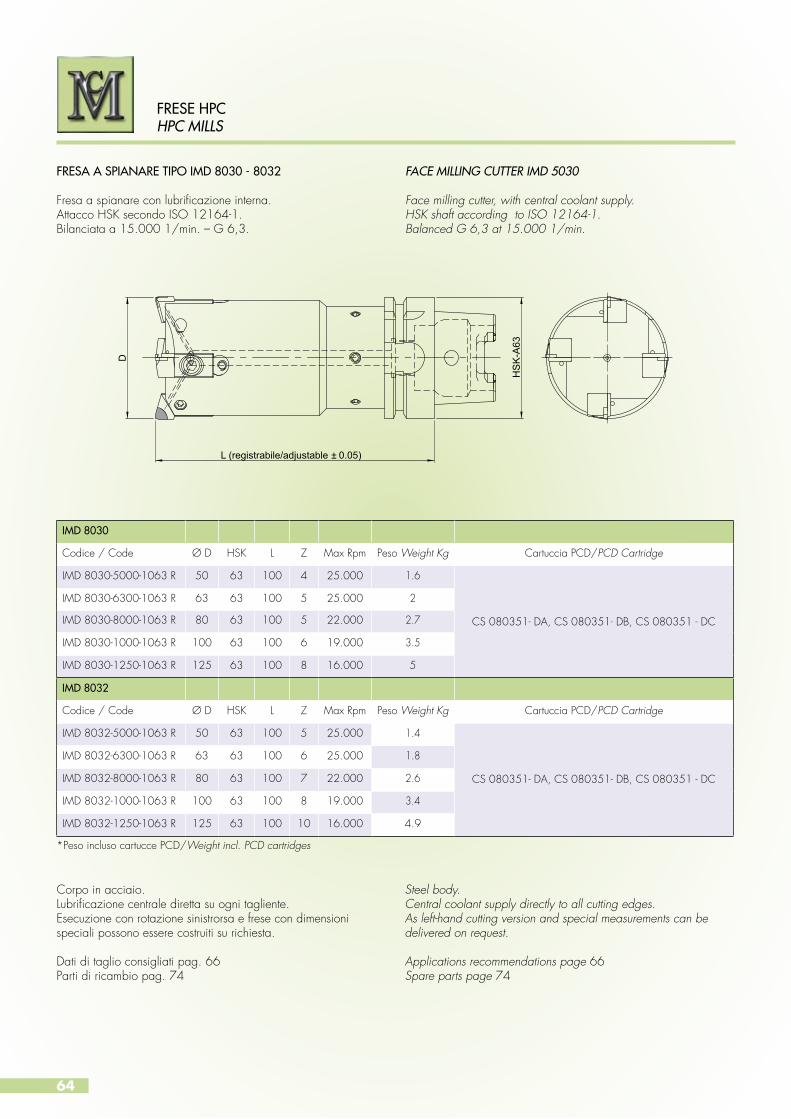
64
FRESE HPCHPC MILLS
FRESA A SPIANARE TIPO IMD 8030 - 8032
Fresa a spianare con lubrificazione interna.Attacco HSK secondo ISO 12164-1.Bilanciata a 15.000 1/min. – G 6,3.
FACE MILLING CUTTER IMD 5030
Face milling cutter, with central coolant supply.HSK shaft according to ISO 12164-1.Balanced G 6,3 at 15.000 1/min.
D
L (registrabile/adjustable ± 0.05)
HS
K-A
63IMD 8030
Codice / Code Ø D HSK L Z Max Rpm Peso Weight Kg Cartuccia PCD/PCD Cartridge
IMD 8030-5000-1063 R 50 63 100 4 25.000 1.6
CS 080351- DA, CS 080351- DB, CS 080351 - DC
IMD 8030-6300-1063 R 63 63 100 5 25.000 2
IMD 8030-8000-1063 R 80 63 100 5 22.000 2.7
IMD 8030-1000-1063 R 100 63 100 6 19.000 3.5
IMD 8030-1250-1063 R 125 63 100 8 16.000 5
IMD 8032
Codice / Code Ø D HSK L Z Max Rpm Peso Weight Kg Cartuccia PCD/PCD Cartridge
IMD 8032-5000-1063 R 50 63 100 5 25.000 1.4
CS 080351- DA, CS 080351- DB, CS 080351 - DC
IMD 8032-6300-1063 R 63 63 100 6 25.000 1.8
IMD 8032-8000-1063 R 80 63 100 7 22.000 2.6
IMD 8032-1000-1063 R 100 63 100 8 19.000 3.4
IMD 8032-1250-1063 R 125 63 100 10 16.000 4.9
Corpo in acciaio.Lubrificazione centrale diretta su ogni tagliente.Esecuzione con rotazione sinistrorsa e frese con dimensioni speciali possono essere costruiti su richiesta.
Dati di taglio consigliati pag. 66Parti di ricambio pag. 74
Steel body.Central coolant supply directly to all cutting edges.As left-hand cutting version and special measurements can be delivered on request.
Applications recommendations page 66Spare parts page 74
*Peso incluso cartucce PCD/Weight incl. PCD cartridges

65
FRESE HPCHPC MILLS
TAGLIENTI IN PCD PER FRESE MD 5030
TAGLIENTI IN PCD PER FRESE MD 5035
TAGLIENTI IN PCD PER FRESE IMD 8030
PCD CUTTING EDGE FOR MILLING IMD 5030
PCD CUTTING EDGE FOR MILLING IMD 5035
PCD CUTTING EDGE FOR MILLING IMD 8030
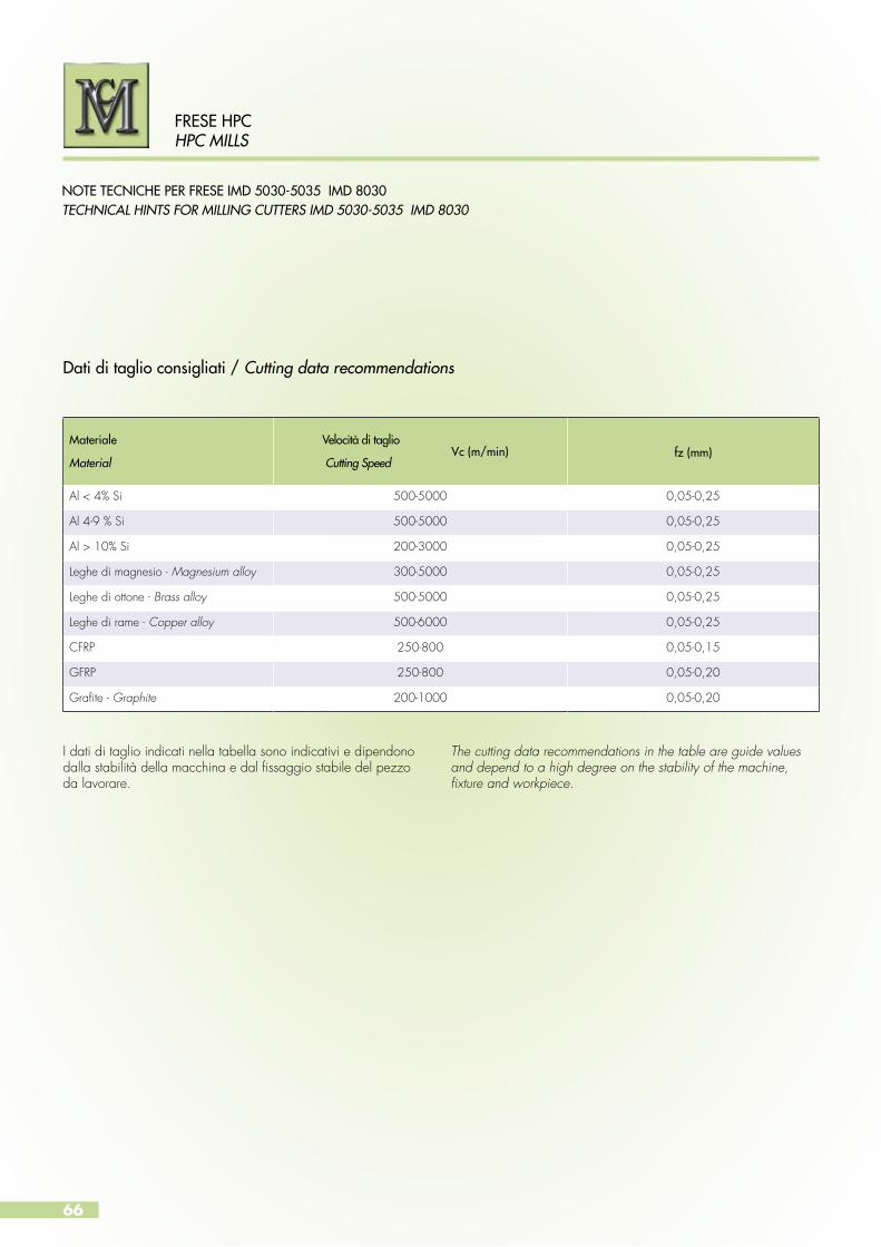
66
FRESE HPCHPC MILLS
NOTE TECNICHE PER FRESE IMD 5030-5035 IMD 8030TECHNICAL HINTS FOR MILLING CUTTERS IMD 5030-5035 IMD 8030
Dati di taglio consigliati / Cutting data recommendations
Materiale
Material
Velocità di taglio
Cutting Speedfz (mm)
Al < 4% Si 500-5000 0,05-0,25
Al 4-9 % Si 500-5000 0,05-0,25
Al > 10% Si 200-3000 0,05-0,25
Leghe di magnesio - Magnesium alloy 300-5000 0,05-0,25
Leghe di ottone - Brass alloy 500-5000 0,05-0,25
Leghe di rame - Copper alloy 500-6000 0,05-0,25
CFRP 250-800 0,05-0,15
GFRP 250-800 0,05-0,20
Grafite - Graphite 200-1000 0,05-0,20
I dati di taglio indicati nella tabella sono indicativi e dipendono dalla stabilità della macchina e dal fissaggio stabile del pezzoda lavorare.
The cutting data recommendations in the table are guide values and depend to a high degree on the stability of the machine, fixture and workpiece.
Vc (m/min)
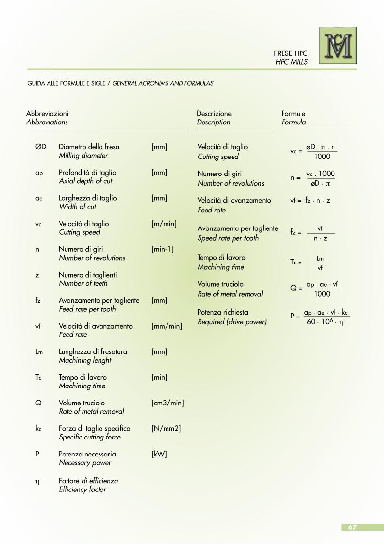
67
FRESE HPCHPC MILLS
GUIDA ALLE FORMULE E SIGLE / GENERAL ACRONIMS AND FORMULAS
ØD Diametro della fresa [mm] Milling diameter
ap Profondità di taglio [mm] Axial depth of cut
ae Larghezza di taglio [mm] Width of cut
vc Velocità di taglio [m/min] Cutting speed
n Numero di giri [min-1] Number of revolutions
z Numero di taglienti Number of teeth
fz Avanzamento per tagliente [mm] Feed rate per tooth
vf Velocità di avanzamento [mm/min] Feed rate
Lm Lunghezza di fresatura [mm] Machining lenght
Tc Tempo di lavoro [min] Machining time
Q Volume truciolo [cm3/min] Rate of metal removal
kc Forza di taglio specifica [N/mm2] Specific cutting force
P Potenza necessaria [kW] Necessary power
η Fattore di efficienza Efficiency factor
Velocità di taglio vc = øD . π . nCutting speed 1000
Numero di giri n = vc . 1000Number of revolutions øD . π Velocità di avanzamento vf = fz . n . z Feed rate
Avanzamento per tagliente fz = vf
Speed rate per tooth n . z
Tempo di lavoro Tc = Lm
Machining time vf
Volume truciolo Q = ap . ae . vf
Rate of metal removal 1000
Potenza richiesta P = ap . ae . vf . kc
Required (drive power) 60 . 106 . η
AbbreviazioniAbbreviations
DescrizioneDescription
FormuleFormula
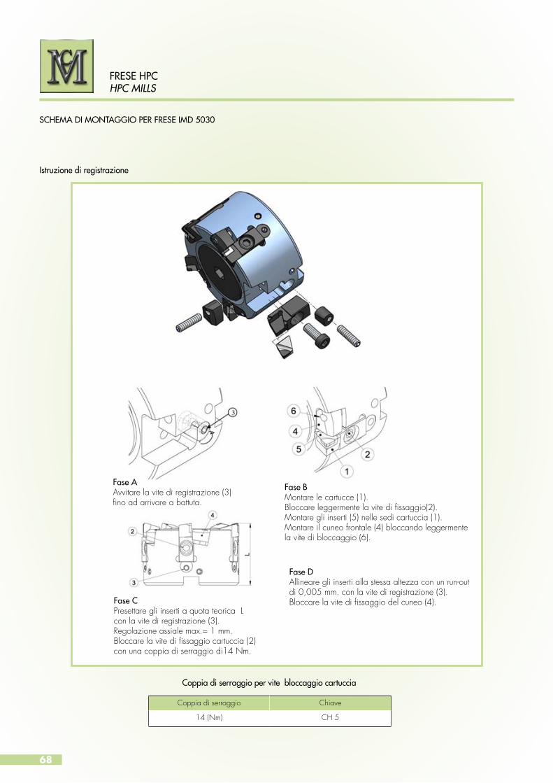
68
FRESE HPCHPC MILLS
SCHEMA DI MONTAGGIO PER FRESE IMD 5030
Istruzione di registrazione
Coppia di serraggio per vite bloccaggio cartuccia
Fase AAvvitare la vite di registrazione (3)fino ad arrivare a battuta.
Fase BMontare le cartucce (1).Bloccare leggermente la vite di fissaggio(2).Montare gli inserti (5) nelle sedi cartuccia (1).Montare il cuneo frontale (4) bloccando leggermente la vite di bloccaggio (6).
Fase CPresettare gli inserti a quota teorica Lcon la vite di registrazione (3).Regolazione assiale max.= 1 mm. Bloccare la vite di fissaggio cartuccia (2)con una coppia di serraggio di14 Nm.
Fase DAllineare gli inserti alla stessa altezza con un run-out di 0,005 mm. con la vite di registrazione (3).Bloccare la vite di fissaggio del cuneo (4).
Coppia di serraggio Chiave
14 (Nm) CH 5
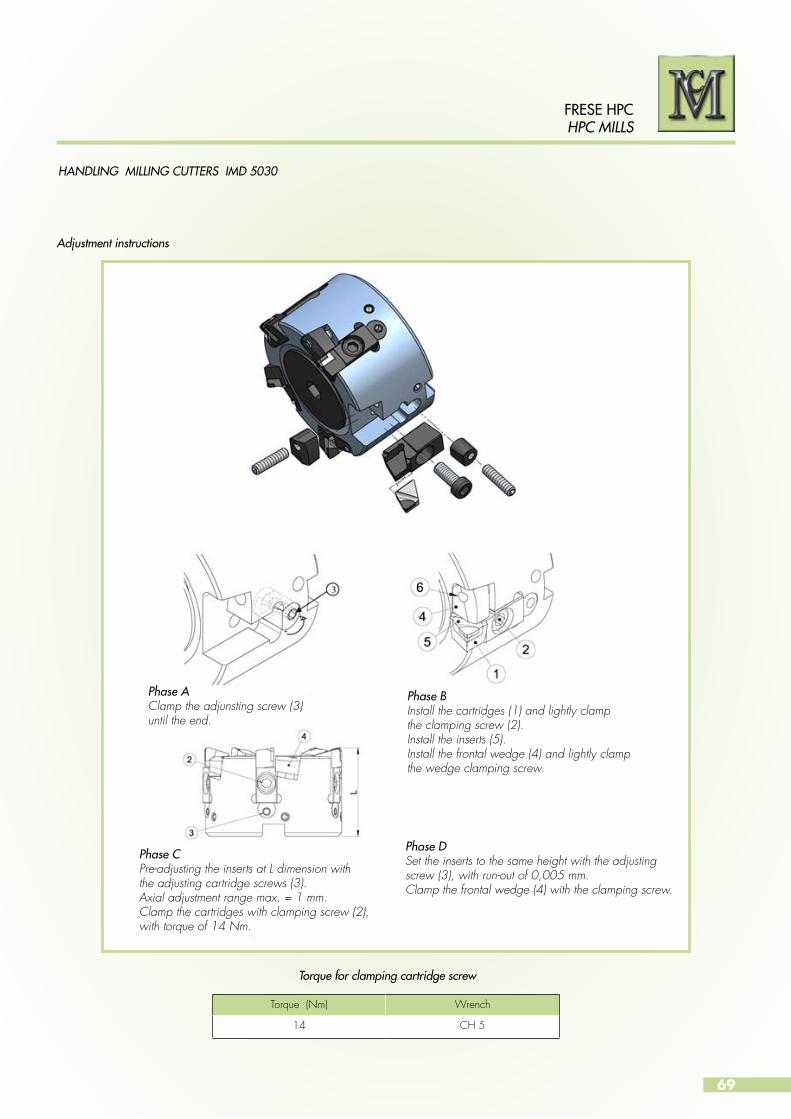
69
FRESE HPCHPC MILLS
HANDLING MILLING CUTTERS IMD 5030
Adjustment instructions
Torque for clamping cartridge screw
Phase AClamp the adjunsting screw (3) until the end.
Phase BInstall the cartridges (1) and lightly clampthe clamping screw (2).Install the inserts (5).Install the frontal wedge (4) and lightly clamp the wedge clamping screw.
Phase CPre-adjusting the inserts at L dimension withthe adjusting cartridge screws (3).Axial adjustment range max. = 1 mm.Clamp the cartridges with clamping screw (2),with torque of 14 Nm.
Phase DSet the inserts to the same height with the adjusting screw (3), with run-out of 0,005 mm.Clamp the frontal wedge (4) with the clamping screw.
Torque (Nm) Wrench
14 CH 5
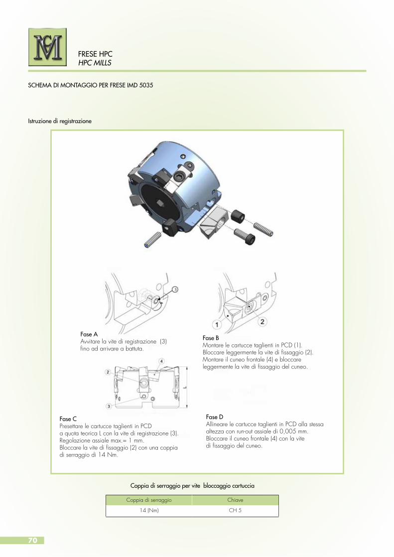
70
FRESE HPCHPC MILLS
SCHEMA DI MONTAGGIO PER FRESE IMD 5035
Istruzione di registrazione
Coppia di serraggio per vite bloccaggio cartuccia
Fase AAvvitare la vite di registrazione (3)fino ad arrivare a battuta.
Fase BMontare le cartucce taglienti in PCD (1).Bloccare leggermente la vite di fissaggio (2).Montare il cuneo frontale (4) e bloccareleggermente la vite di fissaggio del cuneo.
Fase CPresettare le cartucce taglienti in PCDa quota teorica L con la vite di registrazione (3).Regolazione assiale max.= 1 mm. Bloccare la vite di fissaggio (2) con una coppiadi serraggio di 14 Nm.
Fase DAllineare le cartucce taglienti in PCD alla stessa altezza con run-out assiale di 0,005 mm.Bloccare il cuneo frontale (4) con la vitedi fissaggio del cuneo.
Coppia di serraggio Chiave
14 (Nm) CH 5
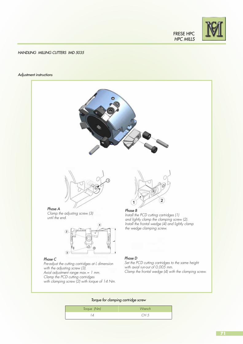
71
FRESE HPCHPC MILLS
HANDLING MILLING CUTTERS IMD 5035
Adjustment instructions
Torque for clamping cartridge screw
Phase AClamp the adjusting screw (3)until the end.
Phase BInstall the PCD cutting cartridges (1)and lightly clamp the clamping screw (2).Install the frontal wedge (4) and lightly clampthe wedge clamping screw.
Phase CPre-adjust the cutting cartridges at L dimensionwith the adjusting screw (3).Axial adjustment range max.= 1 mm. Clamp the PCD cutting cartridgeswith clamping screw (2) with torque of 14 Nm.
Phase DSet the PCD cutting cartridges to the same height with axial run-out of 0,005 mm.Clamp the frontal wedge (4) with the clamping screw.
Torque (Nm) Wrench
14 CH 5

72
FRESE HPCHPC MILLS
SCHEMA DI MONTAGGIO PER FRESE IMD 8030 - 8032
Istruzione di registrazione
Coppia di serraggio per vite bloccaggio cartuccia
Coppia di serraggio Chiave
14 (Nm) CH 5
Fase AAvvitare la vite di registrazione (3)fino ad arrivare a battuta.
Fase BMontare le cartucce taglienti in PCD (1).Bloccare leggermente la vite di fissaggio (2).Montare il cuneo frontale (4) e bloccareleggermente la vite di fissaggio del cuneo.
Fase CPresettare le cartucce taglienti in PCDa quota teorica L con la vite di registrazione (3).Regolazione assiale max.= 1 mm. Bloccare la vite di fissaggio (2) con una coppiadi serraggio di 14 Nm.
Fase DAllineare le cartucce taglienti in PCDalla stessa altezza con run-out assialedi 0,005 mm.Bloccare il cuneo frontale (4)con la vite di fissaggio del cuneo.
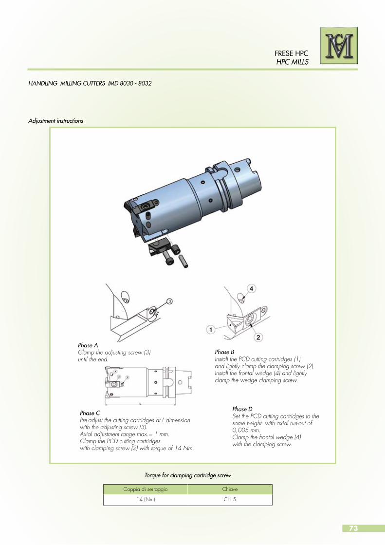
73
FRESE HPCHPC MILLS
HANDLING MILLING CUTTERS IMD 8030 - 8032
Adjustment instructions
Torque for clamping cartridge screw
Coppia di serraggio Chiave
14 (Nm) CH 5
Phase AClamp the adjusting screw (3)until the end.
Phase BInstall the PCD cutting cartridges (1)and lightly clamp the clamping screw (2).Install the frontal wedge (4) and lightly clamp the wedge clamping screw.
Phase CPre-adjust the cutting cartridges at L dimensionwith the adjusting screw (3).Axial adjustment range max.= 1 mm.Clamp the PCD cutting cartridgeswith clamping screw (2) with torque of 14 Nm.
Phase DSet the PCD cutting cartridges to the same height with axial run-out of 0,005 mm.Clamp the frontal wedge (4)with the clamping screw.
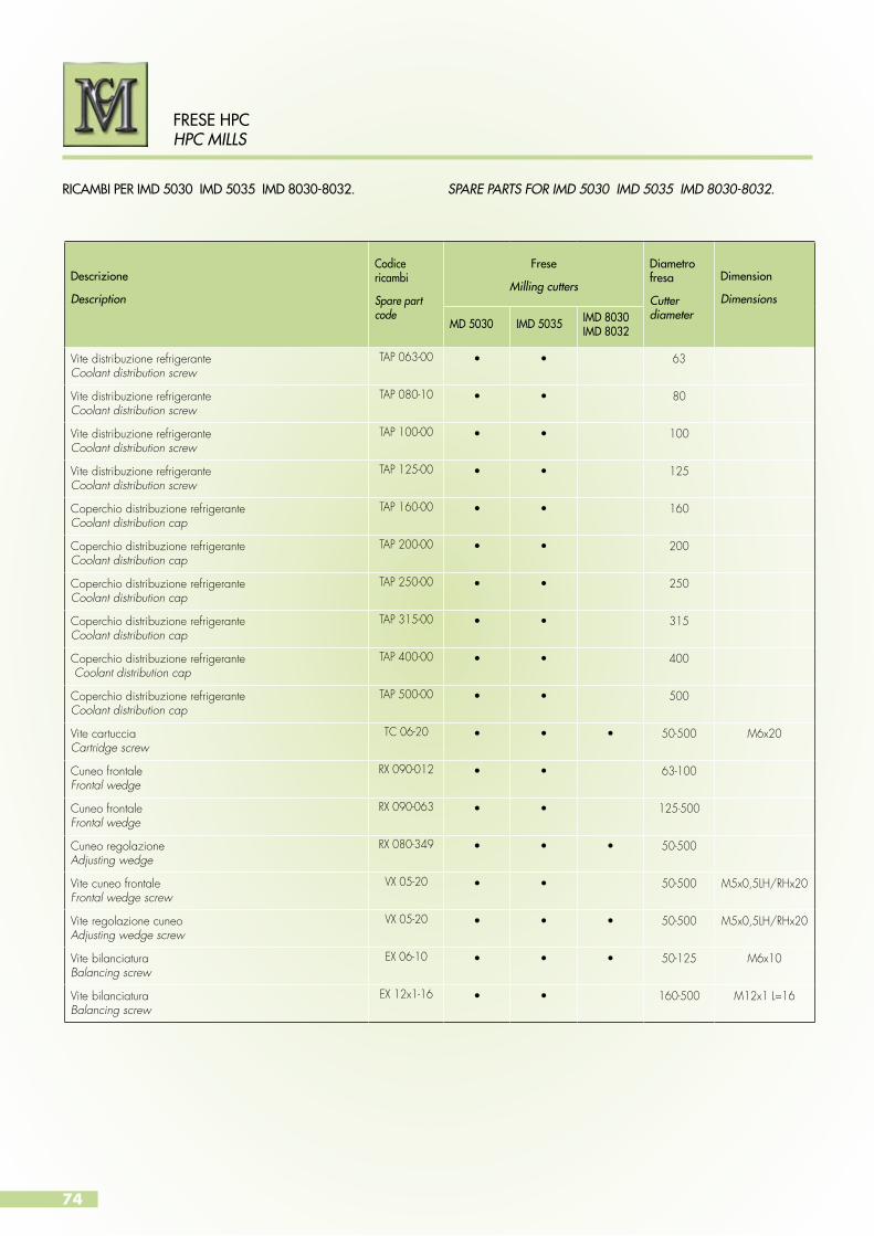
74
RICAMBI PER IMD 5030 IMD 5035 IMD 8030-8032. SPARE PARTS FOR IMD 5030 IMD 5035 IMD 8030-8032.
FRESE HPCHPC MILLS
Descrizione
Description
Codice ricambi
Spare part code
Frese
Milling cutters
Diametro fresa
Cutterdiameter
Dimension
Dimensions
MD 5030 IMD 5035 IMD 8030IMD 8032
Vite distribuzione refrigeranteCoolant distribution screw
TAP 063-00 • • 63
Vite distribuzione refrigeranteCoolant distribution screw
TAP 080-10 • • 80
Vite distribuzione refrigeranteCoolant distribution screw
TAP 100-00 • • 100
Vite distribuzione refrigeranteCoolant distribution screw
TAP 125-00 • • 125
Coperchio distribuzione refrigeranteCoolant distribution cap
TAP 160-00 • • 160
Coperchio distribuzione refrigeranteCoolant distribution cap
TAP 200-00 • • 200
Coperchio distribuzione refrigeranteCoolant distribution cap
TAP 250-00 • • 250
Coperchio distribuzione refrigeranteCoolant distribution cap
TAP 315-00 • • 315
Coperchio distribuzione refrigerante Coolant distribution cap
TAP 400-00 • • 400
Coperchio distribuzione refrigeranteCoolant distribution cap
TAP 500-00 • • 500
Vite cartucciaCartridge screw
TC 06-20 • • • 50-500 M6x20
Cuneo frontaleFrontal wedge
RX 090-012 • • 63-100
Cuneo frontaleFrontal wedge
RX 090-063 • • 125-500
Cuneo regolazioneAdjusting wedge
RX 080-349 • • • 50-500
Vite cuneo frontaleFrontal wedge screw
VX 05-20 • • 50-500 M5x0,5LH/RHx20
Vite regolazione cuneoAdjusting wedge screw
VX 05-20 • • • 50-500 M5x0,5LH/RHx20
Vite bilanciaturaBalancing screw
EX 06-10 • • • 50-125 M6x10
Vite bilanciaturaBalancing screw
EX 12x1-16 • • 160-500 M12x1 L=16
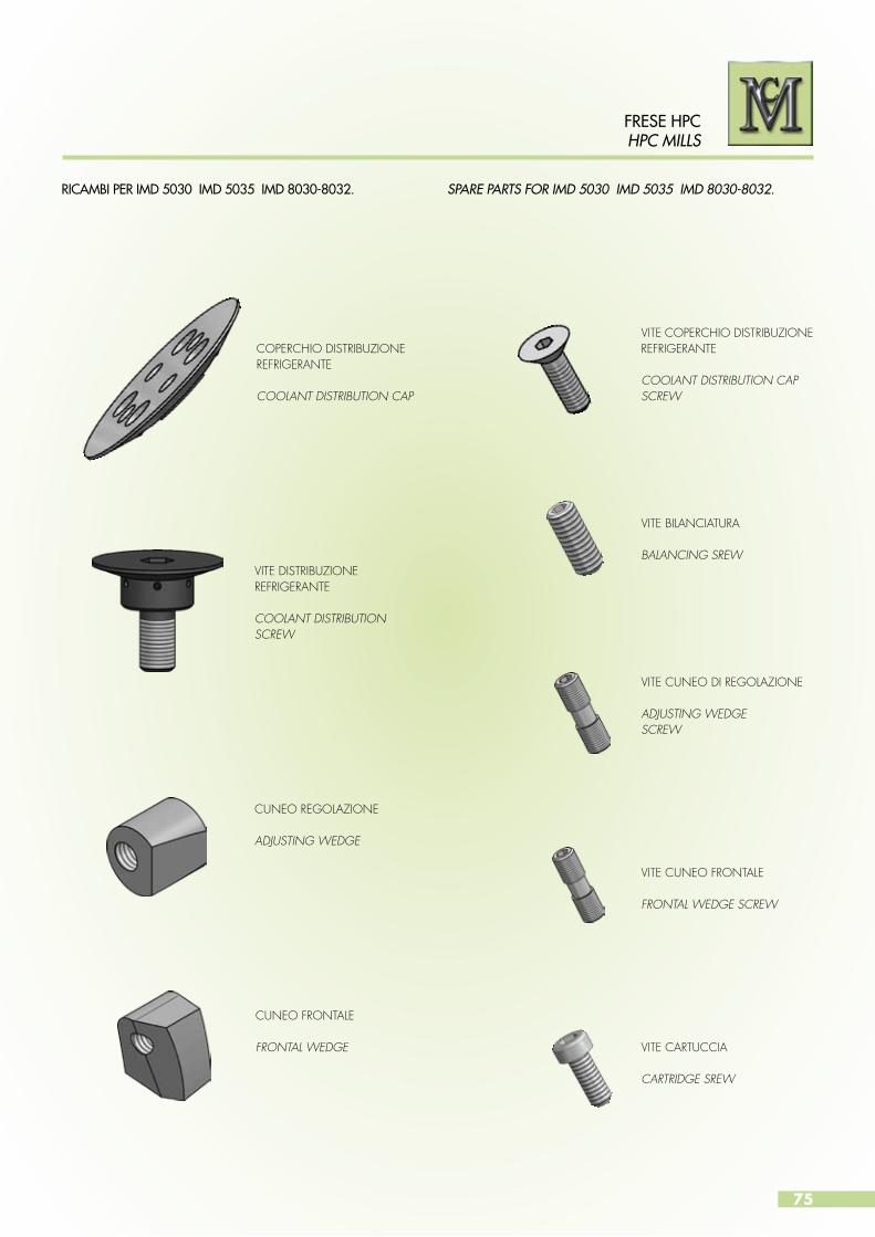
75
FRESE HPCHPC MILLS
RICAMBI PER IMD 5030 IMD 5035 IMD 8030-8032. SPARE PARTS FOR IMD 5030 IMD 5035 IMD 8030-8032.
CUNEO FRONTALE
FRONTAL WEDGE VITE CARTUCCIA
CARTRIDGE SREW
VITE DISTRIBUZIONE REFRIGERANTE
COOLANT DISTRIBUTION SCREW
CUNEO REGOLAZIONE
ADJUSTING WEDGE
VITE COPERCHIO DISTRIBUZIONE REFRIGERANTE
COOLANT DISTRIBUTION CAP SCREW
VITE BILANCIATURA
BALANCING SREW
VITE CUNEO FRONTALE
FRONTAL WEDGE SCREW
VITE CUNEO DI REGOLAZIONE
ADJUSTING WEDGESCREW
COPERCHIO DISTRIBUZIONE REFRIGERANTE
COOLANT DISTRIBUTION CAP
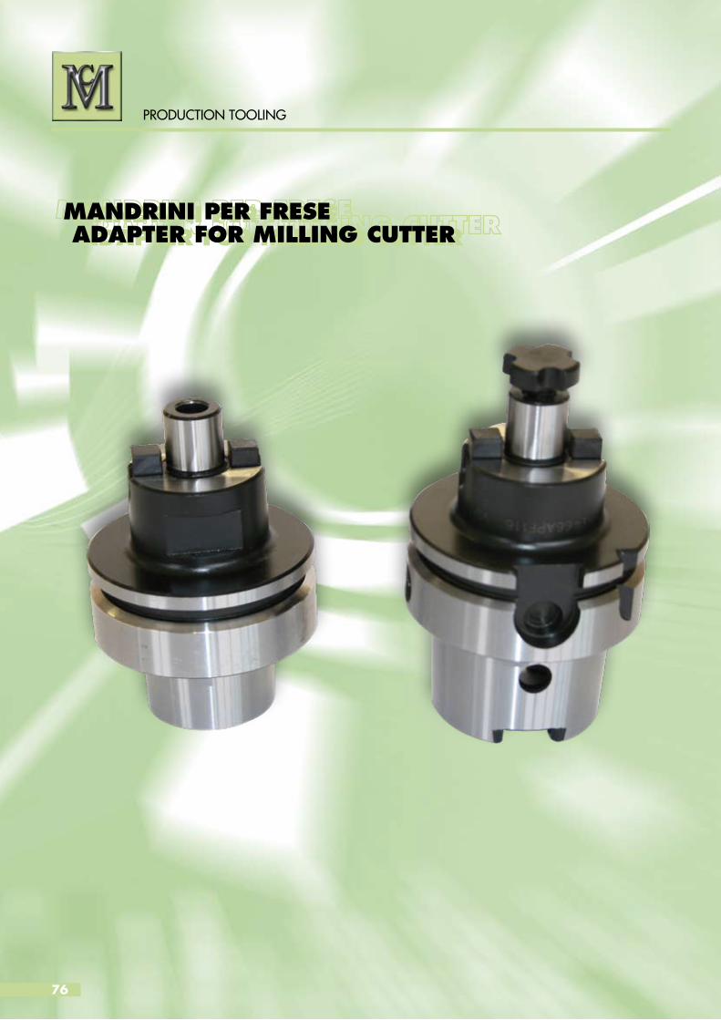
76
PRODUCTION TOOLING
MANDRINI PER FRESE ADAPTER FOR MILLING CUTTERMANDRINI PER FRESE ADAPTER FOR MILLING CUTTER

77
PRODUCTION TOOLING
MANDRINI PER FRESE CON ATTACCO FILETTATO
Prolunga in acciaio con lubrificazione interna. Attacco cilindrico filettato.
ADAPTER FOR SCREW-ON TYPE MILLING CUTTER
Steel extension with internal coolant supply.Cylindrical connection for threaded modular system.
dD2
D1
D h
6
L
L1
CIL 1040
Codice / Code Ø D Ø D1 Ø D2 L L1 d
CIL 1040-1300-7016 16 13 8,5 130 70 M8
CIL 1040-1300-1016 16 13 8,5 160 100 M8
CIL 1040-1800-8020 20 18 10,5 140 80 M10
CIL 1040-1800-1220 20 18 10,5 180 120 M10
CIL 1040-2100-9025 25 21 12,5 160 90 M12
CIL 1040-2100-1325 25 21 12,5 200 130 M12
CIL 1040-2900-9032 32 29 17 160 90 M16
CIL 1040-2900-1332 32 29 17 200 130 M16

78
PRODUCTION TOOLING
MANDRINI PER FRESE CON ATTACCO FILETTATO
Attacco HSK- A 63 secondo DIN 69893.Bilanciato a 20.000 1/min. – G 2,5.
ADAPTER FOR SCREW-ON TYPE MILLING CUTTER
Shaft HSK – A 63 according to DIN 69893.Balanced G 2,5 at 20.000 1/min.
DIN 69893FORMA A - STYLE A
HS
K
D D1
d
L
CPA 6610
Codice / Code HSK Ø D Ø D1 L Ø d
CPA 6610-1300-5963 63 13 8,5 59 M8
CPA 6610-1800-5963 63 18 10,5 59 M10
CPA 6610-2100-5963 63 21 12,5 59 M12
CPA 6610-2900-5963 63 29 17 59 M16
CPA 6610-1300-8463 63 13 8,5 84 M8
CPA 6610-1800-8463 63 18 10,5 84 M10
CPA 6610-2100-8463 63 21 12,5 84 M12
CPA 6610-2900-8463 63 29 17 84 M16
CPA 6610-1300-1063 63 13 8,5 109 M8
CPA 6610-1800-1063 63 18 10,5 109 M10
CPA 6610-2100-1063 63 21 12,5 109 M12
CPA 6610-2900-1063 63 29 17 109 M16
CPA 6610-1300-1363 63 13 8,5 134 M8
CPA 6610-1800-1363 63 18 10,5 134 M10
CPA 6610-2100-1363 63 21 12,5 134 M12
CPA 6610-2900-1363 63 29 17 134 M16
CPA 6610-1800-1563 63 18 10,5 159 M10
CPA 6610-2100-1563 63 21 12,5 159 M12
CPA 6610-2900-1563 63 29 17 159 M16
CPA 6610-2100-1863 63 21 12,5 184 M12
CPA 6610-2900-1863 63 29 17 184 M16
CPA 6610-2100-2063 63 21 12,5 209 M12
CPA 6610-2900-2063 63 29 17 209 M16
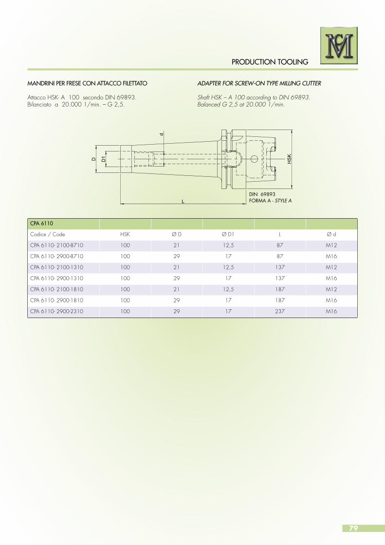
79
PRODUCTION TOOLING
MANDRINI PER FRESE CON ATTACCO FILETTATO
Attacco HSK- A 100 secondo DIN 69893.Bilanciato a 20.000 1/min. – G 2,5.
ADAPTER FOR SCREW-ON TYPE MILLING CUTTER
Shaft HSK – A 100 according to DIN 69893.Balanced G 2,5 at 20.000 1/min.
DIN 69893FORMA A - STYLE A
HS
K
D D1
d
L
CPA 6110
Codice / Code HSK Ø D Ø D1 L Ø d
CPA 6110- 2100-8710 100 21 12,5 87 M12
CPA 6110- 2900-8710 100 29 17 87 M16
CPA 6110- 2100-1310 100 21 12,5 137 M12
CPA 6110- 2900-1310 100 29 17 137 M16
CPA 6110- 2100-1810 100 21 12,5 187 M12
CPA 6110- 2900-1810 100 29 17 187 M16
CPA 6110- 2900-2310 100 29 17 237 M16

80
PRODUCTION TOOLING
MANDRINI PER FRESE CON ATTACCO FILETTATO
Attacco ISO 40 secondo DIN 69871 AD/B.Bilanciato A 20.000 1/min. – G 2,5.
ADAPTER FOR SCREW-ON TYPE MILLING CUTTER
Shaft ISO 40 according to DIN 69871AD/B.Balanced G 2,5 at 20.000 1/min.
DIN 69871FORMA AD/B - STYLE AD/B
D D1
d
L
CPA 1410
Codice / Code ISO / SK Ø D Ø D1 L Ø d
CPA 1410 -1300-5540 40 13 8,5 55 M8
CPA 1410 -1800-5540 40 18 10,5 55 M10
CPA 1410 -2100-5540 40 21 12,5 55 M12
CPA 1410 -2900-5540 40 29 17 55 M16
CPA 1410 -1300-7540 40 13 8,5 75 M8
CPA 1410 -1800-7540 40 18 10,5 75 M10
CPA 1410 -2100-7540 40 21 12,5 75 M12
CPA 1410 -2900-7540 40 29 17 75 M16
CPA 1410 -1300-9540 40 13 8,5 95 M8
CPA 1410 -1800-9540 40 18 10,5 95 M10
CPA 1410 -2100-9540 40 21 12,5 95 M12
CPA 1410 -2900-9540 40 29 17 95 M16
CPA 1410 -1300-1140 40 13 8,5 115 M8
CPA 1410 -1800-1140 40 18 10,5 115 M10
CPA 1410 -2100-1140 40 21 12,5 115 M12
CPA 1410 -2900-1140 40 29 17 115 M16
CPA 1410 -1800-1440 40 18 10,5 145 M10
CPA 1410 -2100-1440 40 21 12,5 145 M12
CPA 1410 -2900-1440 40 29 17 145 M16
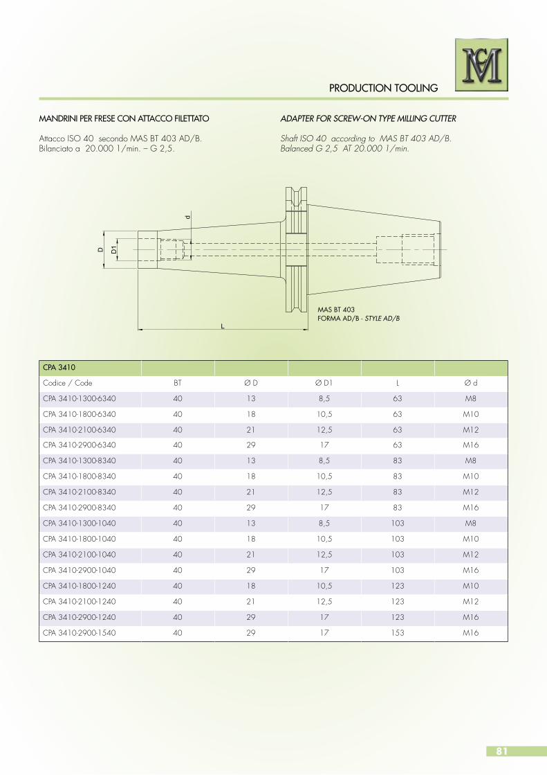
81
PRODUCTION TOOLING
MANDRINI PER FRESE CON ATTACCO FILETTATO
Attacco ISO 40 secondo MAS BT 403 AD/B.Bilanciato a 20.000 1/min. – G 2,5.
ADAPTER FOR SCREW-ON TYPE MILLING CUTTER
Shaft ISO 40 according to MAS BT 403 AD/B.Balanced G 2,5 AT 20.000 1/min.
MAS BT 403FORMA AD/B - STYLE AD/B
D D1
d
L
CPA 3410
Codice / Code BT Ø D Ø D1 L Ø d
CPA 3410-1300-6340 40 13 8,5 63 M8
CPA 3410-1800-6340 40 18 10,5 63 M10
CPA 3410-2100-6340 40 21 12,5 63 M12
CPA 3410-2900-6340 40 29 17 63 M16
CPA 3410-1300-8340 40 13 8,5 83 M8
CPA 3410-1800-8340 40 18 10,5 83 M10
CPA 3410-2100-8340 40 21 12,5 83 M12
CPA 3410-2900-8340 40 29 17 83 M16
CPA 3410-1300-1040 40 13 8,5 103 M8
CPA 3410-1800-1040 40 18 10,5 103 M10
CPA 3410-2100-1040 40 21 12,5 103 M12
CPA 3410-2900-1040 40 29 17 103 M16
CPA 3410-1800-1240 40 18 10,5 123 M10
CPA 3410-2100-1240 40 21 12,5 123 M12
CPA 3410-2900-1240 40 29 17 123 M16
CPA 3410-2900-1540 40 29 17 153 M16

82
PRODUCTION TOOLING
MANDRINI PORTAFRESA TIPO 6620
Mandrini portafresa attacco HSK-A 63 secondo DIN 69893.Bilanciato 20.000 1/min. – G 6,3.
ACE MILL HOLDERS TYPE 6620
Face mill holders, shaft HSK-A 63 according to DIN 69893.Balanced G 6,3 at 20.000 1/min.
DIN 69893FORMA A - STYLE A
Dd
LL1
HS
K
CPA 6620
Codice / Code HSK Ø D L L1 Ø d
CPA 6620 - 1600 - 5063 63 16 50 17 38
CPA 6620 - 2200 - 5063 63 22 50 19 48
CPA 6620 - 2700 - 6063 63 27 60 21 58
CPA 6620 - 3200 - 6063 63 32 60 24 66
CPA 6620 - 4000 - 6063 63 40 60 27 80
CPA 6620 - 1600 - 1063 63 16 100 17 38
CPA 6620 - 2200 - 1063 63 22 100 19 48
CPA 6620 - 2700 - 1063 63 27 100 21 58
CPA 6620 - 3200 - 1063 63 32 100 24 66
CPA 6620 - 4000 - 1063 63 40 100 27 80
CPA 6620
Diametro mandrinoHolder diameter
Tassello Key for spindleCodice / Code
Vite tasselloKey screw
Codice / Code
Vite a croceCross head screwCodice / Code
16 916TSL01 110301001 916VTC02
22 922TSL01 110301201 922VTC02
27 927TSL01 110401601 927VTC02
32 932TSL01 110601601 932VTC02
40 940TSL01 110601601 940VTC02
RICAMBI / SPARE PARTS
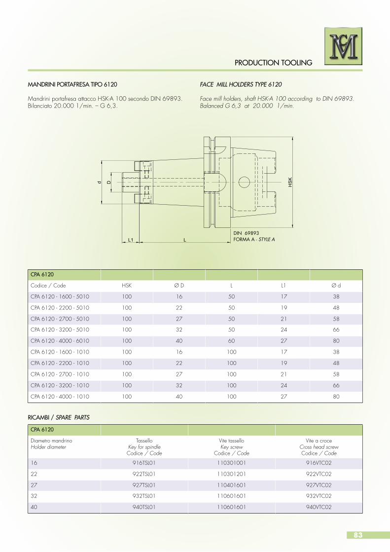
83
PRODUCTION TOOLING
MANDRINI PORTAFRESA TIPO 6120
Mandrini portafresa attacco HSK-A 100 secondo DIN 69893.Bilanciato 20.000 1/min. – G 6,3.
FACE MILL HOLDERS TYPE 6120
Face mill holders, shaft HSK-A 100 according to DIN 69893.Balanced G 6,3 at 20.000 1/min.
DIN 69893FORMA A - STYLE A
Dd
LL1
HS
K
RICAMBI / SPARE PARTS
CPA 6120
Codice / Code HSK Ø D L L1 Ø d
CPA 6120 - 1600 - 5010 100 16 50 17 38
CPA 6120 - 2200 - 5010 100 22 50 19 48
CPA 6120 - 2700 - 5010 100 27 50 21 58
CPA 6120 - 3200 - 5010 100 32 50 24 66
CPA 6120 - 4000 - 6010 100 40 60 27 80
CPA 6120 - 1600 - 1010 100 16 100 17 38
CPA 6120 - 2200 - 1010 100 22 100 19 48
CPA 6120 - 2700 - 1010 100 27 100 21 58
CPA 6120 - 3200 - 1010 100 32 100 24 66
CPA 6120 - 4000 - 1010 100 40 100 27 80
CPA 6120
Diametro mandrinoHolder diameter
Tassello Key for spindleCodice / Code
Vite tasselloKey screw
Codice / Code
Vite a croceCross head screwCodice / Code
16 916TSL01 110301001 916VTC02
22 922TSL01 110301201 922VTC02
27 927TSL01 110401601 927VTC02
32 932TSL01 110601601 932VTC02
40 940TSL01 110601601 940VTC02

84
PRODUCTION TOOLING
MANDRINI PORTAFRESA TIPO CPA 1420
Mandrini portafresa attacco ISO 40 secondo DIN 69871 AD/ B.Bilanciati 12.000 1/min. – G 6,3.
FACE MILL HOLDERS TYPE CPA 1420
Face mill holders, shaft SK40 according to DIN 69871AD / B.Balanced G 6,3 at 20.000 1/min.
DIN 69871FORMA AD/B - STYLE AD/B
Dd
LL1
CPA 1420
Codice / Code ISO / SK D L L1 d
CPA 1420 - 1600 - 3540 40 16 35 17 38
CPA 1420 - 2200 - 3540 40 22 35 19 48
CPA 1420 - 2700 - 3540 40 27 35 21 58
CPA 1420 - 3200 - 3540 40 32 35 24 78
CPA 1420 - 1600 - 4540 40 16 45 17 38
CPA 1420 - 2200 - 4540 40 22 45 19 48
CPA 1420 - 2700 - 5040 40 27 50 21 58
CPA 1420 - 3200 - 5540 40 32 55 24 78
CPA 1420 - 4000 - 5540 40 40 55 27 88
CPA 1420
Diametro mandrinoHolder diameter
Tassello Key for spindleCodice / Code
Vite tasselloKey screw
Codice / Code
Vite a croceCross head screwCodice / Code
16 916TSL01 110301001 916VTC02
22 922TSL01 110301201 922VTC02
27 927TSL01 110401601 927VTC02
32 932TSL01/04 110601601 932VTC02
40 940TSL01 110601601 940VTC02
RICAMBI / SPARE PARTS

85
PRODUCTION TOOLING
MANDRINI PORTAFRESA TIPO CPA 3420
Mandrini portafresa attacco MAS 403/ BT AD/ B.Bilanciati 12.000 1/min. – G 6,3.
FACE MILL HOLDERS TYPE CPA 3420
Face mill holders, shaft MAS 403/BT AD/B.Balanced G 6,3 AT 12.000 1/min.
MAS BT 403FORMA AD/B - STYLE AD/B
Dd
LL1
RICAMBI / SPARE PARTS
CPA 3420
Codice / Code BT D L L1 d
CPA 3420 - 1600 - 3540 40 16 35 17 46
CPA 3420 - 2200 - 3540 40 22 35 19 59
CPA 3420 - 2700 - 3540 40 27 35 21 58
CPA 3420 - 1600 - 4540 40 16 45 17 38
CPA 3420 - 2200 - 4540 40 22 45 19 48
CPA 3420 - 2700 - 4540 40 27 45 21 58
CPA 3420 - 3200 - 5040 40 32 50 24 78
CPA 3420 - 4000 - 5540 40 40 55 27 88
CPA 3420
Diametro mandrinoHolder diameter
Tassello Key for spindleCodice / Code
Vite tasselloKey screw
Codice / Code
Vite a croceCross head screwCodice / Code
16 916TSL01 110301001 916VTC02
22 922TSL01 110301201 922VTC02
27 927TSL01 110401601 927VTC02
32 932TSL01 110601601 932VTC02
40 940TSL01 110601601 940VTC02

86
PRODUCTION TOOLING
Alesatura, barenatura, allargatura
I ns. utensili in PCD sono realizzati con la massima precisione e garantiscono un utilizzo sicuro per ogni tipo di lavorazione.Grazie ad una esperienza pluriennale MC interpreta le esigenze dei suoi clienti fornendo le giuste soluzioni.Il ns. impegno è diretto a fornire soluzioni complete e vantaggiose che ottimizzino il ciclo produttivo.La ns. competenza nel settore degli utensili in PCD é costantemente confermata dalla produzione giornaliera dei ns. utensili.Diverse sono le versioni, dagli utensili bitaglienti agli utensili con 4 - 6 - 8 e più taglienti.Gli utensili possono essere realizzati con corpi in acciaio o in metallo duro integrale, per garantire la massima rigidità.I corpi in metallo duro vengono utilizzati soprattutto per la costruzione di utensili di piccolo diametro.Si possono realizzare utensili a più diametri, in tal modo si riducono i tempi passivi, aumentando di conseguenza l’economicità nelle lavorazioni. Offriamo soluzioni integrate innovative con la costruzione di utensili a più taglienti, che realizzano contemporaneamente lavorazioni di più diametri, smussi, raggi, lamature con tolleranze di lavorazione molto strette ed eccellenti qualità di superficie.Anche la lavorazione di scanalature o di profili esterni possono essere eseguite con i ns. utensili in PCD.Le innumerevoli possibili combinazioni dei taglienti in PCD consentono di poter eseguire molte lavorazioni con un solo utensile e quindi con notevoli vantaggi. I ns. utensili vengono prodotti con estrema accuratezza e garantiscono una lavorazione precisa.I taglienti realizzati con la massima precisione con tolleranze inferiori ai 3 microns garantiscono ottime prestazioni.La ns. produzione verte sopratutto su utensili speciali, che vengono
UTENSILI IN PCD
realizzati per tutte le produzioni che richiedono un solo utensile che combini molteplici lavorazioni come smussi, raggi, lamature e più diametri.Oltre agli alesatori ed allargatori a taglienti fissi in PCD, il ns. programma di produzione comprende anche la costruzione di utensili con inserti intercambiabili in PCD e la produzione di barenatori multitaglienti con pattini di guida e lame intercambiabili in PCD che sfruttano il principio degli alesatori lama pattino.In questo catalogo vengono proposti utensili standard con 4, 6 e 8 taglienti.Oltre agli alesatori fissi per fori passanti e fori ciechi della serie BRD 4060 e BRD 4062, che sono utilizzati con successo presso importanti aziende, abbiamo ora sviluppato gli alesatori con testina intercambiabile della serie BRD 6060 per fori passanti e della serie BRD 6062 per fori ciechi. Per garantire la precisione di rotazione necessaria e quindi per evitare gli errori di rotazione causati dal mandrino macchina, gli alesatori con testina intercambiabile utilizzano sistemi di fissaggio con attacchi modulari.Questi attacchi modulari consentono di poter effettuare la registrazione assiale e radiale e di ottenerre una concentricità di rotazione entro i 3 microns. I vantaggi che possono essere ottenuti con questi attacchi modulari, che sono ora disponibili in una ampia gamma di tipologie, sono evidenti non solo sulla qualità dei fori prodotti, ma anche per lo sforzo ridotto dell’utensile assicurando quindi una vita più lunga all’utensile ed una migliore affidabilità di processo. Grazie alla adduzione del refrigerante diretta sui taglienti gli alesatori della serie BRD 4060, BRD 4062, BRD 6060, BRD 6062 possono essere impiegati anche con la lubrificazione minimale.
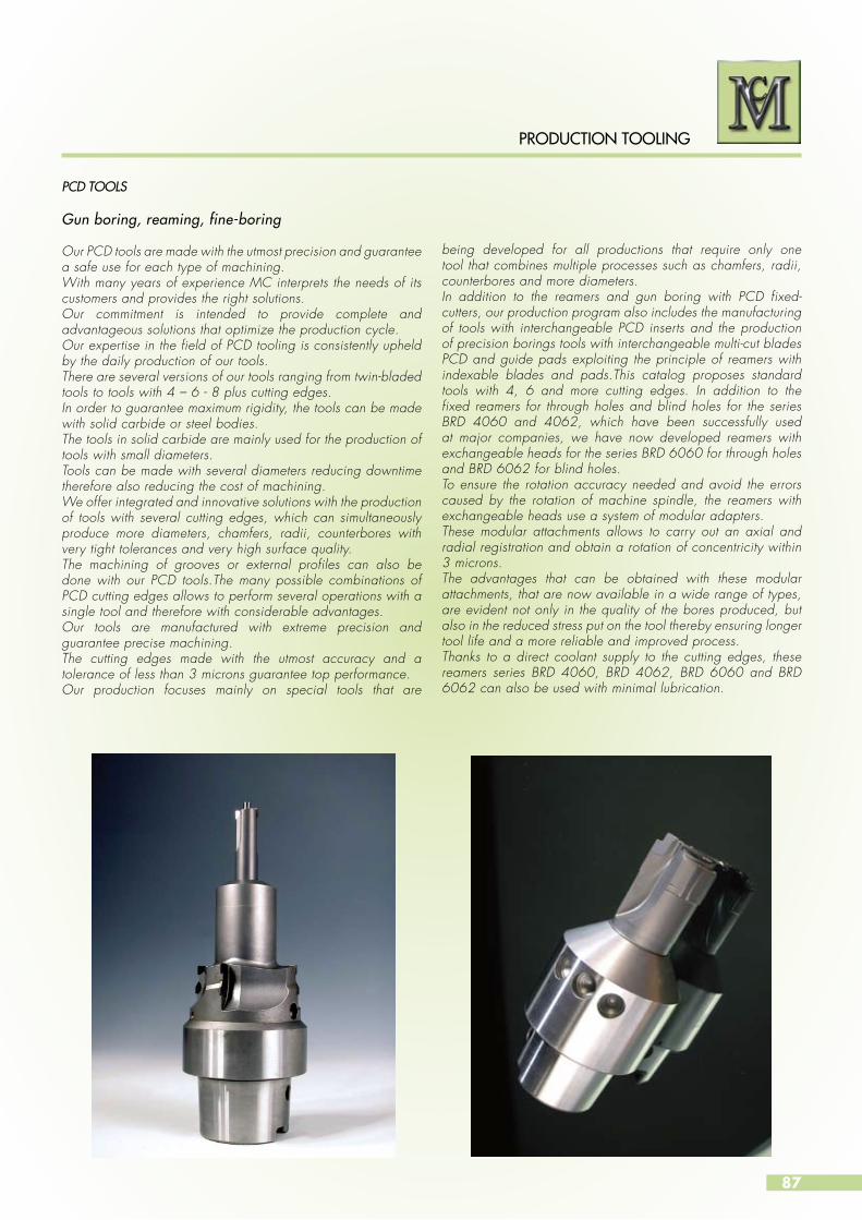
87
PRODUCTION TOOLING
Gun boring, reaming, fine-boring
Our PCD tools are made with the utmost precision and guarantee a safe use for each type of machining.With many years of experience MC interprets the needs of its customers and provides the right solutions.Our commitment is intended to provide complete and advantageous solutions that optimize the production cycle. Our expertise in the field of PCD tooling is consistently upheld by the daily production of our tools. There are several versions of our tools ranging from twin-bladed tools to tools with 4 – 6 - 8 plus cutting edges.In order to guarantee maximum rigidity, the tools can be made with solid carbide or steel bodies.The tools in solid carbide are mainly used for the production of tools with small diameters.Tools can be made with several diameters reducing downtime therefore also reducing the cost of machining.We offer integrated and innovative solutions with the production of tools with several cutting edges, which can simultaneously produce more diameters, chamfers, radii, counterbores with very tight tolerances and very high surface quality.The machining of grooves or external profiles can also be done with our PCD tools.The many possible combinations of PCD cutting edges allows to perform several operations with a single tool and therefore with considerable advantages.Our tools are manufactured with extreme precision and guarantee precise machining.The cutting edges made with the utmost accuracy and a tolerance of less than 3 microns guarantee top performance.Our production focuses mainly on special tools that are
PCD TOOLS
being developed for all productions that require only one tool that combines multiple processes such as chamfers, radii, counterbores and more diameters.In addition to the reamers and gun boring with PCD fixed-cutters, our production program also includes the manufacturing of tools with interchangeable PCD inserts and the production of precision borings tools with interchangeable multi-cut blades PCD and guide pads exploiting the principle of reamers with indexable blades and pads.This catalog proposes standard tools with 4, 6 and more cutting edges. In addition to the fixed reamers for through holes and blind holes for the series BRD 4060 and 4062, which have been successfully used at major companies, we have now developed reamers with exchangeable heads for the series BRD 6060 for through holes and BRD 6062 for blind holes.To ensure the rotation accuracy needed and avoid the errors caused by the rotation of machine spindle, the reamers with exchangeable heads use a system of modular adapters.These modular attachments allows to carry out an axial and radial registration and obtain a rotation of concentricity within 3 microns.The advantages that can be obtained with these modular attachments, that are now available in a wide range of types, are evident not only in the quality of the bores produced, but also in the reduced stress put on the tool thereby ensuring longer tool life and a more reliable and improved process.Thanks to a direct coolant supply to the cutting edges, these reamers series BRD 4060, BRD 4062, BRD 6060 and BRD 6062 can also be used with minimal lubrication.
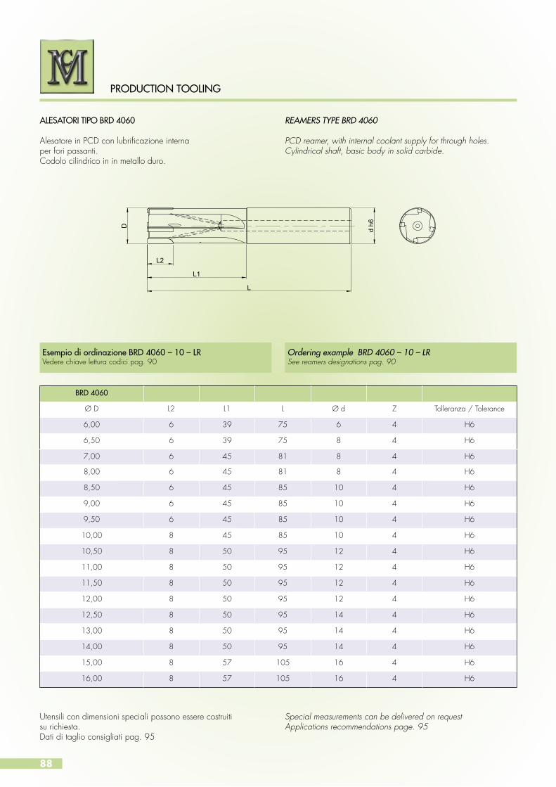
88
PRODUCTION TOOLING
ALESATORI TIPO BRD 4060
Alesatore in PCD con lubrificazione internaper fori passanti.Codolo cilindrico in in metallo duro.
Utensili con dimensioni speciali possono essere costruitisu richiesta. Dati di taglio consigliati pag. 95
Special measurements can be delivered on requestApplications recommendations page. 95
REAMERS TYPE BRD 4060
PCD reamer, with internal coolant supply for through holes.Cylindrical shaft, basic body in solid carbide.
D d h6
L
L1
L2
BRD 4060
Ø D L2 L1 L Ø d Z Tolleranza / Tolerance
6,00 6 39 75 6 4 H6
6,50 6 39 75 8 4 H6
7,00 6 45 81 8 4 H6
8,00 6 45 81 8 4 H6
8,50 6 45 85 10 4 H6
9,00 6 45 85 10 4 H6
9,50 6 45 85 10 4 H6
10,00 8 45 85 10 4 H6
10,50 8 50 95 12 4 H6
11,00 8 50 95 12 4 H6
11,50 8 50 95 12 4 H6
12,00 8 50 95 12 4 H6
12,50 8 50 95 14 4 H6
13,00 8 50 95 14 4 H6
14,00 8 50 95 14 4 H6
15,00 8 57 105 16 4 H6
16,00 8 57 105 16 4 H6
Esempio di ordinazione BRD 4060 – 10 – LRVedere chiave lettura codici pag. 90
Ordering example BRD 4060 – 10 – LRSee reamers designations pag. 90

89
PRODUCTION TOOLING
ALESATORI TIPO BRD 4062
Alesatore in PCD con lubrificazione interna per fori ciechi.Codolo cilindrico in in metallo duro.
Utensili con dimensioni speciali possono essere costruitisu richiesta. Dati di taglio consigliati pag. 95
Special measurements can be delivered on request.Applications recommendations page. 95
REAMERS TYPE BRD 4062
PCD reamer, with central coolant supply for blind holes.Cylindrical shaft, basic body in solid carbide.
D d h6
L
L1
L2
Esempio di ordinazione BRD 4062 – 10 – LR Vedere chiave lettura codici pag. 90
Ordering example BRD 4062 – 10 – LRSee reamers designations pag. 90
BRD 4062
Ø D L2 L1 L Ø d Z Tolleranza / Tolerance
6,00 6 39 75 6 4 H6
6,50 6 39 75 8 4 H6
7,00 8 45 81 8 4 H6
8,00 8 45 81 8 4 H6
8,50 8 45 85 10 4 H6
9,00 8 45 85 10 4 H6
9,50 8 45 85 10 4 H6
10,00 8 45 85 10 4 H6
10,50 8 50 95 12 4 H6
11,00 8 50 95 12 4 H6
11,50 8 50 95 12 4 H6
12,00 8 50 95 12 4 H6
12,50 8 50 95 14 4 H6
13,00 8 50 95 14 4 H6
14,00 8 50 95 14 4 H6
15,00 8 57 105 16 4 H6
16,00 8 57 105 16 4 H6

90
PRODUCTION TOOLING
REAMERS BRD 4060-4062 DESIGNATIONCHIAVE DI LETTURA DEI CODICI DEGLI ALESATORIBRD 4060-4062
Esempio di ordinazione
BRD 4060 – 10 – LR 1 2 3 4
1. Codice prodotto
BRD Alesatore
2. Codice tipo
4060 - 4062 Tipo
3. Diametro
10 Ø D
4. Imbocco
Ordering example
BRD 4060 – 10 – LR 1 2 3 4
1. Product code
BRD Reamer
2. Code type
4060 - 4062 Type
3. Diameter
10 Ø D
4. Imbocco
Imbocco / Lead Geometria / Geometry
LR 0,5 x 45°
LW 0,3 x 75°
LF 0,3x75° / 0,5x5°

91
PRODUCTION TOOLING
CUTTING GEOMETRYGEOMETRIA DI TAGLIO
0,5 x 45°0°
0,3 x 75°0°
0,3 x 75° / 0,5 x 5°0°
Dedescrizione dell’imboccoLead angle
Angoli spogliaRake angle
ImboccoLead

92
PRODUCTION TOOLING
ALESATORI TIPO BRD 6060
Testina di alesatura in PCD con lubrificazione internaper fori passanti. Codolo cilindrico filettato in acciaio.
Utensili con dimensioni speciali possono essere costruitisu richiesta. Dati di taglio consigliati pag. 95
Special measurements can be delivered on request.Applications recommendations page 95
REAMERS TYPE BRD 6060
PCD reaming head, with internal coolant supplyfor through holes.Ciylindrical shaft as s screw, steel basic body.
D
L
L1
Esempio di ordinazione BRD 6060 – 16,5 – H7 - LR Vedere chiave lettura codici pag. 94
Ordering example BRD 6060 – 16,5 – H7 - LRSee reamers designations page 94
BRD 6060
Ø D L1 L Z Grandezza / Size
16,00 – 19,99 8 15 4 15
20,00 – 24,99 10 20 4 19
25,00 – 28,99 10 25 6 24
29,00 – 33,99 10 25 6 28
34,00 – 39,99 10 30 6 33
40,00 – 44,99 10 30 6 39
45,00 – 49,99 10 35 6 44
50,00 – 60,00 10 35 6 49
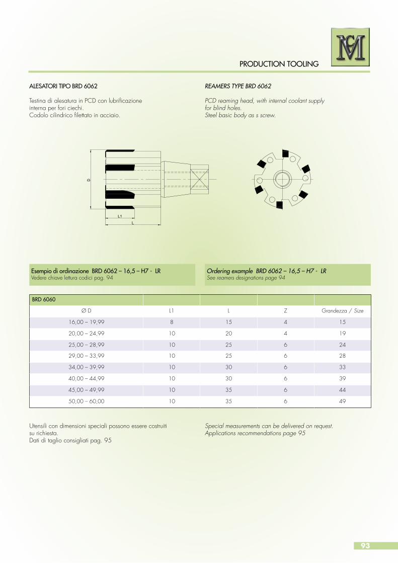
93
PRODUCTION TOOLING
ALESATORI TIPO BRD 6062
Testina di alesatura in PCD con lubrificazioneinterna per fori ciechi.Codolo cilindrico filettato in acciaio.
REAMERS TYPE BRD 6062
PCD reaming head, with internal coolant supplyfor blind holes.Steel basic body as s screw.
Utensili con dimensioni speciali possono essere costruitisu richiesta.Dati di taglio consigliati pag. 95
Special measurements can be delivered on request.Applications recommendations page 95
D
L
L1
Esempio di ordinazione BRD 6062 – 16,5 – H7 - LR Vedere chiave lettura codici pag. 94
Ordering example BRD 6062 – 16,5 – H7 - LRSee reamers designations page 94
BRD 6060
Ø D L1 L Z Grandezza / Size
16,00 – 19,99 8 15 4 15
20,00 – 24,99 10 20 4 19
25,00 – 28,99 10 25 6 24
29,00 – 33,99 10 25 6 28
34,00 – 39,99 10 30 6 33
40,00 – 44,99 10 30 6 39
45,00 – 49,99 10 35 6 44
50,00 – 60,00 10 35 6 49

94
PRODUCTION TOOLING
REAMERS BRD 6060-6062 DESIGNATIONCHIAVE DI LETTURA DEI CODICI DEGLI ALESATORIBRD 6060-6062
Esempio di ordinazione
BRD 6060 – 16,5 – H7 - LR 1 2 3 4 5
1. Codice prodotto
BRD Alesatore
2. Codice tipo
6060 - 6062 Tipo
3. Diametro
16 Ø D
4. Tolleranza
H 7
5. Imbocco
Ordering example
BRD 6060 – 16,5 – H7 - LR 1 2 3 4 5
1. Product code
BRD Reamer
2. Code type
6060 - 6062 Type
3. Diameter
16 Ø D
4. Tolerance
H 7
5. Lead
CUTTING GEOMETRYGEOMETRIA DI TAGLIO
Dedescrizione dell’imboccoLead angle
Angoli spogliaRake angle
ImboccoLead
0,5 x 45°0°
0,3 x 75°0°
0,3 x 75° / 0,5 x 5°0°
Imbocco / Lead Geometria / Geometry
LR 0,5 x 45°
LW 0,3 x 75°
LF 0,3x75° / 0,5x5°
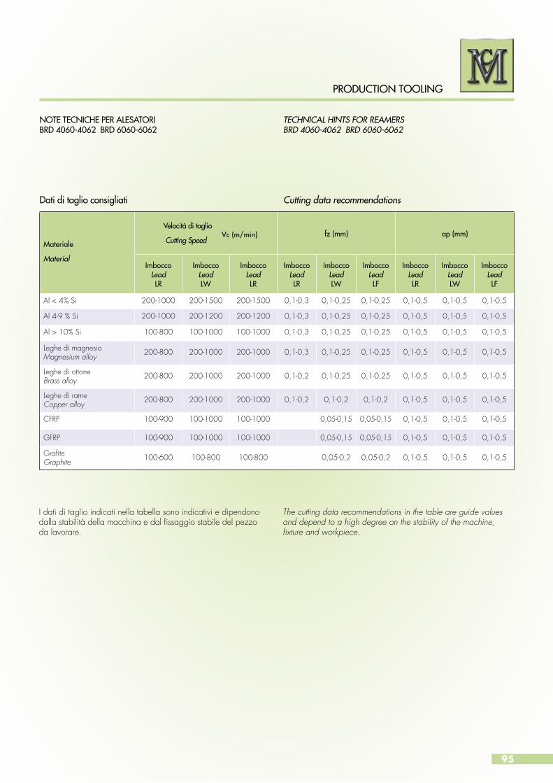
95
PRODUCTION TOOLING
NOTE TECNICHE PER ALESATORIBRD 4060-4062 BRD 6060-6062
Dati di taglio consigliati
TECHNICAL HINTS FOR REAMERS BRD 4060-4062 BRD 6060-6062
Cutting data recommendations
Materiale
Material
Velocità di taglio
Cutting Speedfz (mm) ap (mm)
ImboccoLeadLR
ImboccoLeadLW
ImboccoLeadLR
ImboccoLeadLR
ImboccoLeadLW
ImboccoLeadLF
ImboccoLeadLR
ImboccoLeadLW
ImboccoLeadLF
Al < 4% Si 200-1000 200-1500 200-1500 0,1-0,3 0,1-0,25 0,1-0,25 0,1-0,5 0,1-0,5 0,1-0,5
Al 4-9 % Si 200-1000 200-1200 200-1200 0,1-0,3 0,1-0,25 0,1-0,25 0,1-0,5 0,1-0,5 0,1-0,5
Al > 10% Si 100-800 100-1000 100-1000 0,1-0,3 0,1-0,25 0,1-0,25 0,1-0,5 0,1-0,5 0,1-0,5
Leghe di magnesio Magnesium alloy 200-800 200-1000 200-1000 0,1-0,3 0,1-0,25 0,1-0,25 0,1-0,5 0,1-0,5 0,1-0,5
Leghe di ottoneBrass alloy 200-800 200-1000 200-1000 0,1-0,2 0,1-0,25 0,1-0,25 0,1-0,5 0,1-0,5 0,1-0,5
Leghe di rameCopper alloy 200-800 200-1000 200-1000 0,1-0,2 0,1-0,2 0,1-0,2 0,1-0,5 0,1-0,5 0,1-0,5
CFRP 100-900 100-1000 100-1000 0,05-0,15 0,05-0,15 0,1-0,5 0,1-0,5 0,1-0,5
GFRP 100-900 100-1000 100-1000 0,05-0,15 0,05-0,15 0,1-0,5 0,1-0,5 0,1-0,5
GrafiteGraphite 100-600 100-800 100-800 0,05-0,2 0,05-0,2 0,1-0,5 0,1-0,5 0,1-0,5
I dati di taglio indicati nella tabella sono indicativi e dipendono dalla stabilità della macchina e dal fissaggio stabile del pezzoda lavorare.
The cutting data recommendations in the table are guide values and depend to a high degree on the stability of the machine, fixture and workpiece.
Vc (m/min)

96
PRODUCTION TOOLING
ADATTATORI TIPO CSH 1060 - 1260
Adattatori con attacco cilindrico secondo DIN 1835- Aper alesatori in PCD BRD 6060.
HOLDER TYPE CSH 1060 - 1260
Holder with cylindrical shaft accordingto DIN 1835-A for PCD reamers BRD 6060.
D d2
d1
L2L1
L
L3
Adattatori con dimensioni speciali possono esserecostruiti su richiesta.
Special measurements can be delivered on request.
CSH 1060
Codice / Code Ø D L3 L2 L1 L Ø d1 Ø d2
CSH 1060-1600-1520 16,00 - 19,99 15 50 90 140 15,5 20
CSH 1060-2000-2020 20,00 - 24,99 20 50 110 160 19,3 20
CSH 106 -2500-2525 25,00 - 28,99 25 56 114 170 24,3 25
CSH 1060-2900-2525 29,00 - 33,99 25 56 114 170 28,3 25
CSH 1060-3400-3032 34,00 - 39,99 30 60 120 180 33,2 32
CSH 1060-4000-3032 40,00 - 44,99 30 60 120 180 39,2 32
CSH 1060-4500-3532 45,00 - 49,99 35 60 140 200 44,2 32
CSH 1060-5000-3532 50,00 - 60,00 35 60 140 200 49,2 32
CSH 1260
Codice / Code Ø D L3 L2 L1 L Ø d1 Ø d2
CSH 1260-1600-1520 16,00 - 19,99 15 50 60 110 15,5 20
CSH 1260-2000-2020 20,00 - 24,99 20 50 80 130 19,3 20
CSH 1260-2500-2525 25,00 - 28,99 25 56 84 140 24,3 25
CSH 1260-2900-2525 29,00 - 33,99 25 56 84 140 28,3 25
CSH 1260-3400-3032 34,00 - 39,99 30 60 90 150 33,2 32
CSH 1260-4000-3032 40,00 - 44,99 30 60 90 150 39,2 32
CSH 1260-4500-3532 45,00 - 49,99 35 60 110 170 44,2 32
CSH 1260-5000-3532 50,00 - 60,00 35 60 110 170 49,2 32
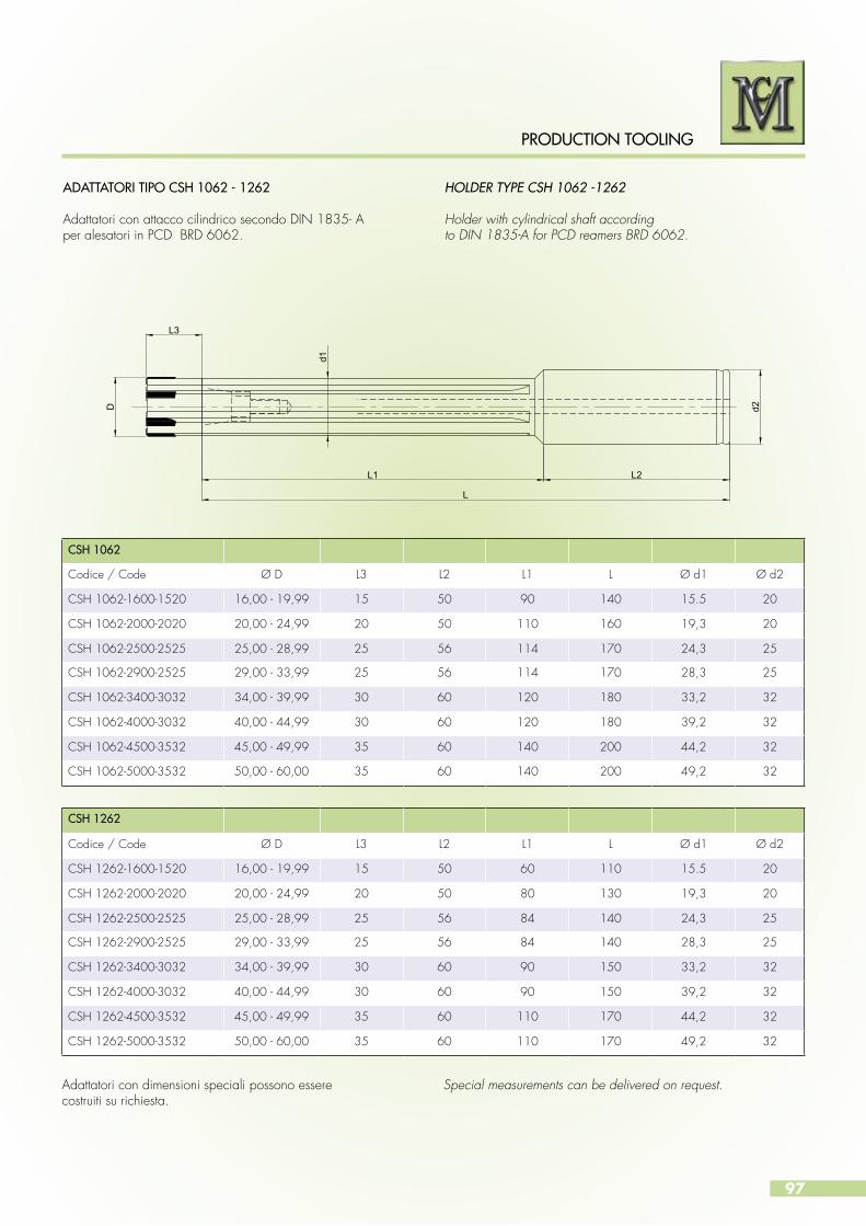
97
PRODUCTION TOOLING
CSH 1062
Codice / Code Ø D L3 L2 L1 L Ø d1 Ø d2
CSH 1062-1600-1520 16,00 - 19,99 15 50 90 140 15.5 20
CSH 1062-2000-2020 20,00 - 24,99 20 50 110 160 19,3 20
CSH 1062-2500-2525 25,00 - 28,99 25 56 114 170 24,3 25
CSH 1062-2900-2525 29,00 - 33,99 25 56 114 170 28,3 25
CSH 1062-3400-3032 34,00 - 39,99 30 60 120 180 33,2 32
CSH 1062-4000-3032 40,00 - 44,99 30 60 120 180 39,2 32
CSH 1062-4500-3532 45,00 - 49,99 35 60 140 200 44,2 32
CSH 1062-5000-3532 50,00 - 60,00 35 60 140 200 49,2 32
CSH 1262
Codice / Code Ø D L3 L2 L1 L Ø d1 Ø d2
CSH 1262-1600-1520 16,00 - 19,99 15 50 60 110 15.5 20
CSH 1262-2000-2020 20,00 - 24,99 20 50 80 130 19,3 20
CSH 1262-2500-2525 25,00 - 28,99 25 56 84 140 24,3 25
CSH 1262-2900-2525 29,00 - 33,99 25 56 84 140 28,3 25
CSH 1262-3400-3032 34,00 - 39,99 30 60 90 150 33,2 32
CSH 1262-4000-3032 40,00 - 44,99 30 60 90 150 39,2 32
CSH 1262-4500-3532 45,00 - 49,99 35 60 110 170 44,2 32
CSH 1262-5000-3532 50,00 - 60,00 35 60 110 170 49,2 32
ADATTATORI TIPO CSH 1062 - 1262
Adattatori con attacco cilindrico secondo DIN 1835- Aper alesatori in PCD BRD 6062.
HOLDER TYPE CSH 1062 -1262
Holder with cylindrical shaft accordingto DIN 1835-A for PCD reamers BRD 6062.
D d2
L2L1
L
L3d1
Adattatori con dimensioni speciali possono esserecostruiti su richiesta.
Special measurements can be delivered on request.

98
PRODUCTION TOOLING
ADATTATORI TIPO CSH 2060
Adattatori con attacco modulare con registrazioneradiale/angolare per alesatori BRD 6060.
HOLDER TYPE CSH 2060
Holder with shaft module radially and angularadjustable for BRD 6060 reamers.
D d2
L
L1
L2
d1
Adattatori con dimensioni speciali possono esserecostruiti su richiesta.
Special measurements can be delivered on request.
CSH 2060
Codice / Code D L2 L1 L d1 d2
CSH 2060-1600-1560 16,00 - 19,99 15 70 85 15.5 60
CSH 2060-2000-2060 20,00 - 24,99 20 75 90 19,3 60
CSH 2060-2500-2560 25,00 - 28,99 25 75 90 24,3 60
CSH 2060-2900-2560 29,00 - 33,99 25 80 95 28,3 60
CSH 2060-3400-3060 34,00 - 39,99 30 85 100 33,2 60
CSH 2060-4000-3060 40,00 - 44,99 30 90 105 39,2 60
CSH 2060-4500-3560 45,00 - 49,99 35 95 110 44,2 60
CSH 2060-5000-3560 50,00 - 60,00 35 105 120 49,2 60
Grandezza modulo Ø d2Module size Ø d2
Vite fissaggio / Clamping screw Grano di regolazione / Adjusting screw Cilindro di protezione / Trust Pad
Dimensione / Dimension Codice / Code Dimensione / Dimension Codice / Code Codice / Code
60 M 5 x 16 TC 06 - 16 M 6 x 8 EX 06 - 08 RX - 98010
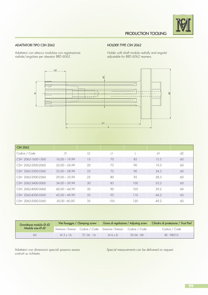
99
PRODUCTION TOOLING
ADATTATORI TIPO CSH 2062
Adattatori con attacco modulare con registrazioneradiale/angolare per alesatori BRD 6062.
HOLDER TYPE CSH 2062
Holder with shaft module radially and angularadjustable for BRD 6062 reamers.
d2D
L
L1
L2
d1
Adattatori con dimensioni speciali possono esserecostruiti su richiesta.
Special measurements can be delivered on request.
CSH 2062
Codice / Code D L2 L1 L d1 d2
CSH 2062-1600-1560 16,00 – 19,99 15 70 85 15.5 60
CSH 2062-2000-2060 20,00 – 24,99 20 75 90 19,3 60
CSH 2062-2500-2560 25,00 – 28,99 25 75 90 24,3 60
CSH 2062-2900-2560 29,00 – 33,99 25 80 95 28,3 60
CSH 2062-3400-3060 34,00 – 39,99 30 85 100 33,2 60
CSH 2062-4000-3060 40,00 – 44,99 30 90 105 39,2 60
CSH 2062-4500-3560 45,00 – 49,99 35 95 110 44,2 60
CSH 2062-5000-3560 50,00 - 60,00 35 105 120 49,2 60
Grandezza modulo Ø d2Module size Ø d2
Vite fissaggio / Clamping screw Grano di regolazione / Adjusting screw Cilindro di protezione / Trust Pad
Dimensione / Dimension Codice / Code Dimensione / Dimension Codice / Code Codice / Code
60 M 5 x 16 TC 06 - 16 M 6 x 8 EX 06 - 08 RX - 98010
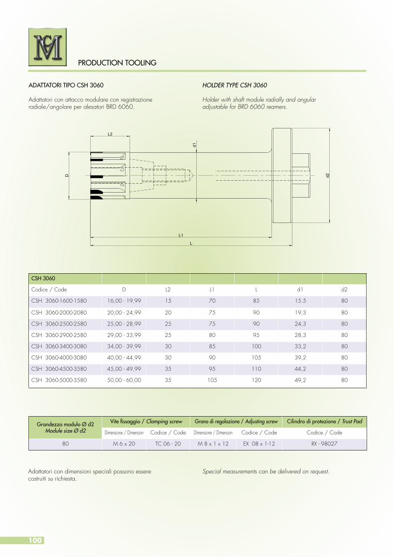
100
PRODUCTION TOOLING
ADATTATORI TIPO CSH 3060
Adattatori con attacco modulare con registrazioneradiale/angolare per alesatori BRD 6060.
HOLDER TYPE CSH 3060
Holder with shaft module radially and angularadjustable for BRD 6060 reamers.
D d2
L
L1
L2
d1
Adattatori con dimensioni speciali possono esserecostruiti su richiesta.
Special measurements can be delivered on request.
CSH 3060
Codice / Code D L2 L1 L d1 d2
CSH 3060-1600-1580 16,00 - 19,99 15 70 85 15.5 80
CSH 3060-2000-2080 20,00 - 24,99 20 75 90 19,3 80
CSH 3060-2500-2580 25,00 - 28,99 25 75 90 24,3 80
CSH 3060-2900-2580 29,00 - 33,99 25 80 95 28,3 80
CSH 3060-3400-3080 34,00 - 39,99 30 85 100 33,2 80
CSH 3060-4000-3080 40,00 - 44,99 30 90 105 39,2 80
CSH 3060-4500-3580 45,00 - 49,99 35 95 110 44,2 80
CSH 3060-5000-3580 50,00 - 60,00 35 105 120 49,2 80
Grandezza modulo Ø d2Module size Ø d2
Vite fissaggio / Clamping screw Grano di regolazione / Adjusting screw Cilindro di protezione / Trust Pad
Dimensione / Dimension Codice / Code Dimensione / Dimension Codice / Code Codice / Code
80 M 6 x 20 TC 06 - 20 M 8 x 1 x 12 EX 08 x 1-12 RX - 98027

101
PRODUCTION TOOLING
ADATTATORI TIPO CSH 3062
Adattatori con attacco modulare con registrazioneradiale/angolare per alesatori BRD 6062.
HOLDER TYPE CSH 3062
Holder with shaft module radially and angularadjustable for BRD 6062 reamers.
d2D
L
L1
L2
d1
Adattatori con dimensioni speciali possono esserecostruiti su richiesta.
Special measurements can be delivered on request.
CSH 2062
Codice / Code D L2 L1 L d1 d2
CSH 3062-1600-1580 16,00 - 19,99 15 70 85 15.5 80
CSH 3062-2000-2080 20,00 - 24,99 20 75 90 19,3 80
CSH 3062-2500-2580 25,00 - 28,99 25 75 90 24,3 80
CSH 3062-2900-2580 29,00 - 33,99 25 80 95 28,3 80
CSH 3062-3400-3080 34,00 - 39,99 30 85 100 33,2 80
CSH 3062-4000-3080 40,00 - 44,99 30 90 105 39,2 80
CSH 3062-4500-3580 45,00 - 49,99 35 95 110 44,2 80
CSH 3062-5000-3580 50,00 - 60,00 35 105 120 49,2 80
Grandezza modulo Ø d2Module size Ø d2
Vite fissaggio / Clamping screw Grano di regolazione / Adjusting screw Cilindro di protezione / Trust Pad
Dimensione / Dimension Codice / Code Dimensione / Dimension Codice / Code Codice / Code
80 M 6 x 20 TC 06 - 20 M 8 x 1 x 12 EX 08 x 1-12 RX - 98027
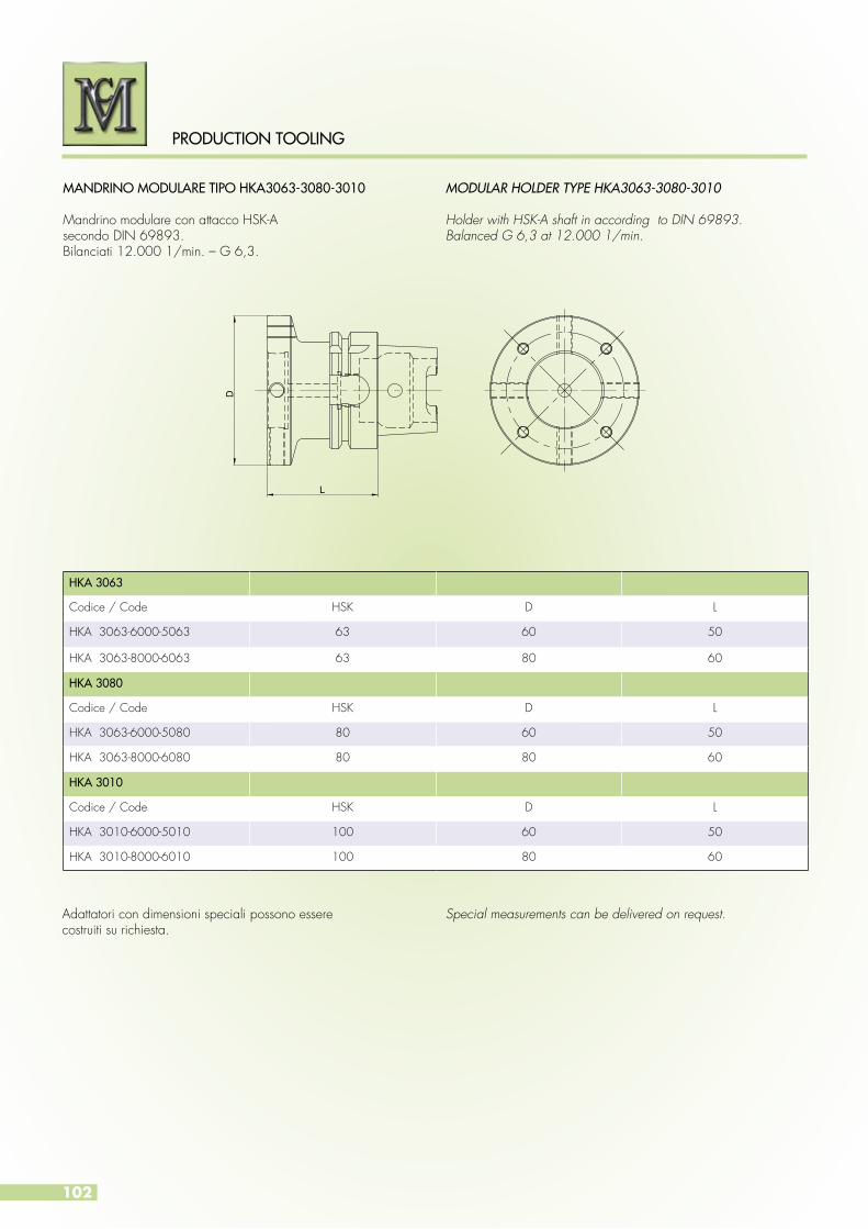
102
PRODUCTION TOOLING
MANDRINO MODULARE TIPO HKA3063-3080-3010
Mandrino modulare con attacco HSK-Asecondo DIN 69893.Bilanciati 12.000 1/min. – G 6,3.
MODULAR HOLDER TYPE HKA3063-3080-3010
Holder with HSK-A shaft in according to DIN 69893.Balanced G 6,3 at 12.000 1/min.
L
D
Adattatori con dimensioni speciali possono esserecostruiti su richiesta.
Special measurements can be delivered on request.
HKA 3063
Codice / Code HSK D L
HKA 3063-6000-5063 63 60 50
HKA 3063-8000-6063 63 80 60
HKA 3080
Codice / Code HSK D L
HKA 3063-6000-5080 80 60 50
HKA 3063-8000-6080 80 80 60
HKA 3010
Codice / Code HSK D L
HKA 3010-6000-5010 100 60 50
HKA 3010-8000-6010 100 80 60
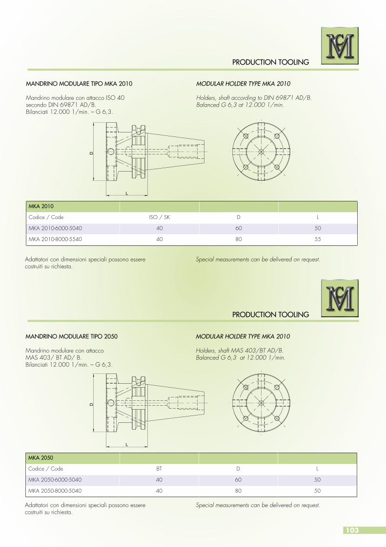
103
PRODUCTION TOOLING
PRODUCTION TOOLING
MANDRINO MODULARE TIPO 2050
Mandrino modulare con attaccoMAS 403/ BT AD/ B.Bilanciati 12.000 1/min. – G 6,3.
MODULAR HOLDER TYPE MKA 2010
Holders, shaft MAS 403/BT AD/B.Balanced G 6,3 at 12.000 1/min.
MKA 2050
Codice / Code BT D L
MKA 2050-6000-5040 40 60 50
MKA 2050-8000-5040 40 80 50
MANDRINO MODULARE TIPO MKA 2010
Mandrino modulare con attacco ISO 40secondo DIN 69871 AD/B.Bilanciati 12.000 1/min. – G 6,3.
MODULAR HOLDER TYPE MKA 2010
Holders, shaft according to DIN 69871 AD/B. Balanced G 6,3 at 12.000 1/min.
L
D
L
D
Adattatori con dimensioni speciali possono esserecostruiti su richiesta.
Adattatori con dimensioni speciali possono esserecostruiti su richiesta.
Special measurements can be delivered on request.
Special measurements can be delivered on request.
MKA 2010
Codice / Code ISO / SK D L
MKA 2010-6000-5040 40 60 50
MKA 2010-8000-5540 40 80 55

104
PRODUCTION TOOLING
Servizio di rigenerazione per utensili in PCD e PCBN
Nella moderna lavorazione ad asportazione di truciolo, è sempre più importante la gestione corretta dell’ordine, sia si tratti di un nuovo utensile che di una rigenerazione, al fine di poter garantire consegne che rispettino i tempi concordati.Oggi non si può più prescindere da tutto ciò.MC garantisce alla propria clientela una assistenza costante e grazie al proprio servizio di rigenerazione e riaffilatura, è in grado di assicurare un lunga durata dei propri utensili.Consegne che rispettino i tempi, aiutano l’utilizzatore.Siamo in grado di garantire il rispetto dei tempi di consegna in quanto provvediamo direttamenteo o tramite il nostro corriere alla consegna presso il cliente.Anche per la rigenerazione, gli utensili possono essere prelevati direttamente da noi o tramite il ns. corriere.Gli utensili da rigenerare vengono innanzitutto puliti con cura.Per gli utensili saldobrasati così come per gli inserti, il tagliente in PCD o PCBN viene sbrasato.Gli utensili vengono poi ulteriormente puliti ed i nuovi taglienti in PCD o PCBN vengono saldati e successivamente viene eseguita una nuova riaffilatura. Nel caso si tratti di frese o di utensili a fissaggio meccanico, dopo lo smontaggio, gli utensili vengolo puliti con cura e le parti usurate vengono sostituite.Gli inserti o le parti taglienti usurate vengono rigenerate e sull’utensile vengono montati nuovi taglienti rigenerati.Tutti gli utensili dopo il montaggio delle parti taglienti, vengono registrati alla misura richiesta.Gli inserti o i taglienti delle frese a fissaggio meccanico, possono essere anche solo riaffilati senza la necessità di dover operare una rigenerazione,solo se l’usura non supera 0,1 mm..
Siamo sempre e costantemente a Vostra disposizione per ulteriori informazioni.
Regeneration service for PCD and PCBN tools
In modern metal stock removal machining, a proper order management is increasingly important, whether it be for a new tool or a regeneration of such in order to guarantee on-time delivery.Today, you can no longer disregard anything.MC offers constant costumer assistance and thanks to its regeneration and regrindiing services, is able to guarantee long lasting tool life.Deliveries that comply with the time set ultimately help the user.We are capable of guaranteeing on-time delivery due to the fact that we provide direct pick-up or delivery through our courier to the client’s location.Even for the regeneration, the tools can be picked up directly from us or delivered through our courier.The tools to be regenerated are first and foremost cleaned thoroughly.For soldered and brazed tools as well as inserts, the cutters in PCD or PCBN will be unbrazed.The tools are then further cleaned and new PCD or PCBN cutters are welded followed by a sharpening of the blades.In the case of milling cutters or tools with mechanical fixing, after disassembly, the tools are thoroughly cleaned and worn out parts are replaced.The worn out inserts or cuttimg parts are regenerated and new regenerated cutting edges are mounted on the tool.All tools, after mounting of the cutting parts, are adjusted according to the requested size.The inserts or blades of the milling cutters with mechanical fixing can be resharpened without the need of a regeneration as long as the wear does not exceed 0,1 mm..
We are always at your disposal for more information.
ASSISTENZA
GESTIONE DELLA RIAFFILATURA / REGRINDING MANAGEMENT
ASSISTANCE
Tel.: + 39 051 60 56 626 - Fax: + 39 051 76 02 28 - E-mail: [email protected]
RICEVIMENTO UTENSILI RECEIPTOF GOOD
CICLO DI RIAFFILATURA REGRINDING CYCLE
CONTROLLO CONTROL
CONSEGNA DELIVERY
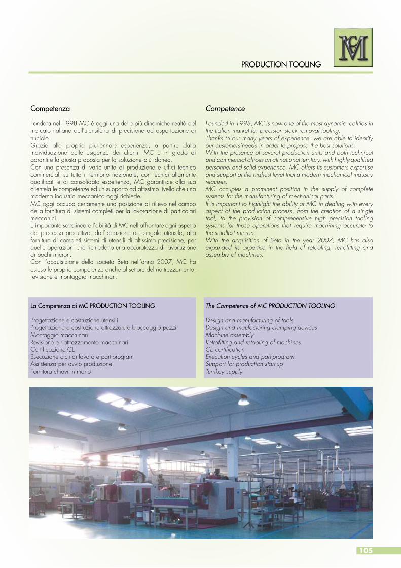
105
PRODUCTION TOOLING
Competenza
Fondata nel 1998 MC è oggi una delle più dinamiche realtà del mercato italiano dell’utensileria di precisione ad asportazione di truciolo.Grazie alla propria pluriennale esperienza, a partire dalla individuazione delle esigenze dei clienti, MC è in grado di garantire la giusta proposta per la soluzione più idonea. Con una presenza di varie unità di produzione e uffici tecnico commerciali su tutto il territorio nazionale, con tecnici altamente qualificati e di consolidata esperienza, MC garantisce alla sua clientela le competenze ed un supporto ad altissimo livello che una moderna industria meccanica oggi richiede.MC oggi occupa certamente una posizione di rilievo nel campo della fornitura di sistemi completi per la lavorazione di particolari meccanici.È importante sottolineare l’abilità di MC nell’affrontare ogni aspetto del processo produttivo, dall’ideazione del singolo utensile, alla fornitura di completi sistemi di utensili di altissima precisione, per quelle operazioni che richiedono una accuratezza di lavorazione di pochi micron.Con l’acquisizione della società Beta nell’anno 2007, MC ha esteso le proprie competenze anche al settore del riattrezzamento, revisione e montaggio macchinari.
La Competenza di MC PRODUCTION TOOLING
Progettazione e costruzione utensiliProgettazione e costruzione attrezzature bloccaggio pezziMontaggio macchinariRevisione e riattrezzamento macchinariCertificazione CEEsecuzione cicli di lavoro e part-programAssistenza per avvio produzioneFornitura chiavi in mano
Competence
Founded in 1998, MC is now one of the most dynamic realities in the Italian market for precision stock removal tooling.Thanks to our many years of experience, we are able to identify our customers’needs in order to propose the best solutions.With the presence of several production units and both technical and commercial offices on all national territory, with highly qualified personnel and solid experience, MC offers its customers expertise and support at the highest level that a modern mechanical industry requires.MC occupies a prominent position in the supply of complete systems for the manufacturing of mechanical parts.It is important to highlight the ability of MC in dealing with every aspect of the production process, from the creation of a single tool, to the provision of comprehensive high precision tooling systems for those operations that require machining accurate to the smallest micron.With the acquisition of Beta in the year 2007, MC has also expanded its expertise in the field of retooling, retrofitting and assembly of machines.
The Competence of MC PRODUCTION TOOLING
Design and manufacturing of toolsDesign and maufactoring clamping devicesMachine assemblyRetrofitting and retooling of machinesCE certificationExecution cycles and part-programSupport for production start-upTurnkey supply
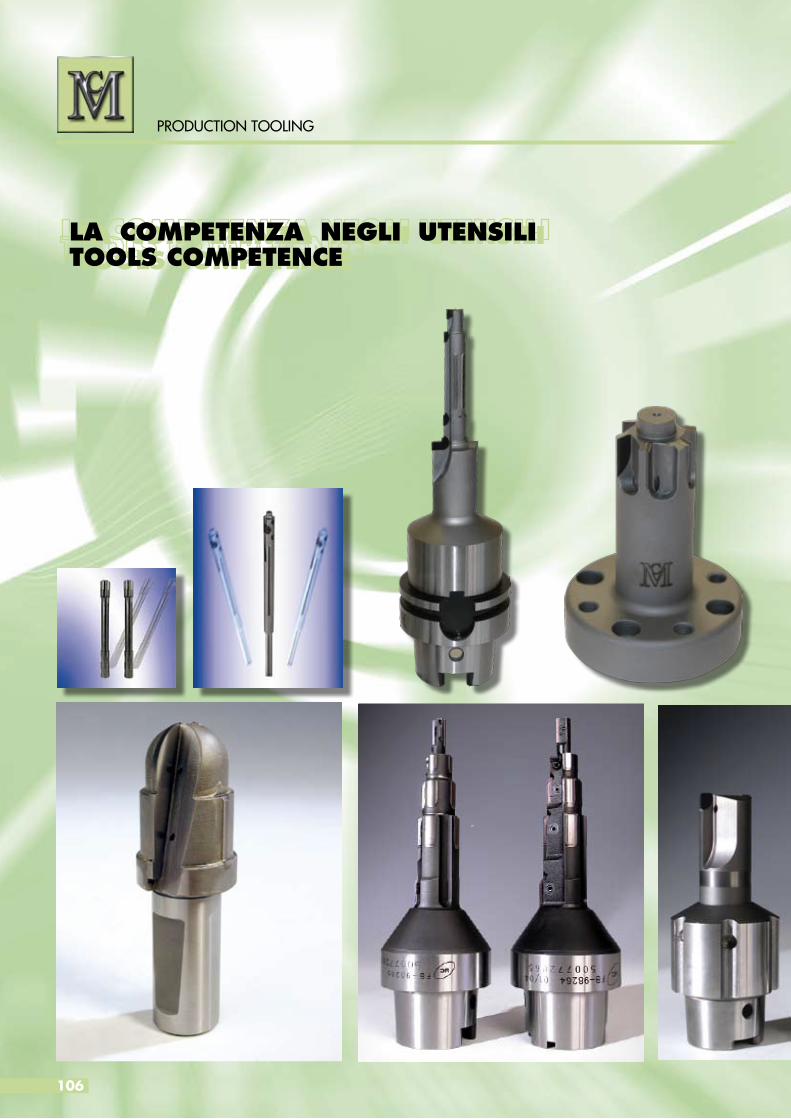
LA COMPETENZA NEGLI UTENSILI TOOLS COMPETENCE
106
PRODUCTION TOOLING
LA COMPETENZA NEGLI UTENSILI TOOLS COMPETENCE
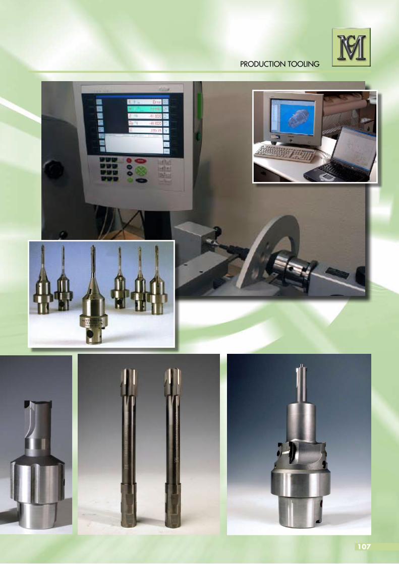
107
PRODUCTION TOOLING

PRODUCTION TOOLING
YOUR IDEAL PARTNER
PRO
DU
CTIO
N T
OO
LIN
G
MC s.a.sVia Viadagola, 15I-40057 Granarolo dell’Emilia (BO)Tel. + 39 051 6056626Fax + 39 051 [email protected]
PRODUCTION TOOLING
PCD - PCBN TOOLS