111220-09mn003-deis appendix 2b-drilling and blasting design-iede
DESCRIPTION
PlanTRANSCRIPT
Kiggavik Project
Environmental Impact Statement
Tier 3 Technical Appendix 2B
Drilling and Blasting Design and Related Regulatory Considerations
December 2011

April 26, 2011
DRILLING AND BLASTING DESIGN AND RELATED REGULATORY CONSIDERATIONS
Kiggavik Project
REP
OR
T
Report Number: 10-1345-0026 Task 3 rev
Distribution:
2 Copies: AREVA Resources Canada Inc., Saskatoon, SK
1 Copy: Golder Associates Ltd., Calgary AB
1 Copy: Golder Associates Ltd., Burnaby BC
1 Copy: Golder Associates Ltd., Sudbury ON
Submitted to:AREVA Resources Canada Inc. Attention: Frederic Guerin, Ph.D., P.Geo. General Manager, Kiggavik-Sissons
KIGGAVIK PROJECT DRILLING AND BLASTING DESIGN
April 26, 2011 Report No. 10-1345-0026 Task 3 rev
Executive Summary AREVA Resources Canada Inc.’s (AREVA’s) Kiggavik property is situated approximately 80 km west of
Baker Lake, Nunavut Territory. The Kiggavik Project can be divided into two main deposit areas: the Kiggavik
area; and the Sissons area. Main, Centre and East Zone deposits are located within the Kiggavik area, while the
Andrew Lake and End Grid deposits are located within the Sissons area, approximately 15 km to 17 km south of
the Kiggavik area. AREVA has retained Golder Associates Ltd. (Golder) to assess drilling and blasting design
for the proposed Kiggavik mining operations.
The study is intended to assess the potential to develop the Kiggavik Project by open pit mining at the Main,
Centre and Andrew Lake deposits and underground mining at the End Grid deposit without incurring blasting
related damage to the proposed infrastructure and local environment yet producing adequately fragmented rock.
This document is a report of Golder’s findings and is based on information provided to us by AREVA, published
literature and Golder’s experience from similar projects.
The original open pit blast designs proposed by AREVA used 150 mm diameter blastholes. Alternate blast designs have been proposed using 187 mm diameter blastholes. These are intended to reduce the cost of drilling and blasting while maintaining the impacts of blasting to below regulatory and non-regulatory limits. In order to limit the water damage to the explosive, which would result in poor blast performance and elevated nitrogen release levels, a doped emulsion of 70/30 (Emulsion/AN) blend is recommended. The potential impacts of blasting at the Kiggavik Project include ground vibrations, potential impact on fisheries, release of nitrogen compounds in mine water, flyrock and fragmentation size distribution produced by the proposed designs.
Golder understands that contract development mining will be retained for primary development and production ore mining at the End Grid underground operations. Therefore, design and implementation of the underground blasts are not included in this report. However, general comments are made regarding the potential for blast-induced impacts and potential methods to mitigate these, if necessary.
In general, there is little potential risk to the proposed infrastructure from vibrations induced by the proposed
blast designs. Flyrock ranges and suggested clearance radii are less than the initially proposed clearance zone
of 500 m. As well, the fragmentation size distribution is estimated to be greater than 95% passing for the
maximum fragment size of 1.0 m.
The study indicates that the most obvious threats to the infrastructure are blast-induced ground vibrations at the Andrew Lake Dewatering Structure and the potential to exceed the Fisheries and Oceans Canada (DFO) limit (13 mm/s) if active spawning beds occur in the water bodies at locations nearest the pit crest. These threats are the highest as the blasting operations approach the proposed ultimate pit crest. As the blasting operations approach the ultimate pit crest, an increased collar and/or decking may be required to maintain vibrations below limits for the Andrew Lake Dewatering Structure and any active spawning beds which may occur near the shores of Andrew Lake closest to the dike.
It is important to remember that the analyses for ground vibrations, flyrock, instantaneous underwater
overpressure and fragmentation presented in this report are based on empirical formulae which are commonly
used in the blasting industry to assess these blasting effects. The models are intended as first approximations
that should be calibrated to provide more refined estimates.

KIGGAVIK PROJECT DRILLING AND BLASTING DESIGN
April 26, 2011 Report No. 10-1345-0026 Task 3 rev
It is suggested that test programs be developed and conducted to calibrate and refine the ground vibration,
flyrock, instantaneous water overpressure and fragmentation model parameters presented in this report. It is
recommended that these be carried out during the initial phases of blasting at Kiggavik. A continued refinement
of the models proposed is recommended in order to provide more accurate estimates and potentially allow for an
optimization of blast designs as the blasting operations continue.
Mines are subject to regulations limiting ammonia, nitrate and nitrite levels in mine effluents released into the
environment. In order to mitigate the potential impacts related to the loss of nitrogen compounds from the
blasting operations, an effective explosives management system should be implemented as part of production
start-up. This should be done for both the open pit and underground operations.
KIGGAVIK PROJECT DRILLING AND BLASTING DESIGN
April 26, 2011 Report No. 10-1345-0026 Task 3 rev i
Table of Contents
1.0 INTRODUCTION ............................................................................................................................................................... 5
2.0 GEOTECHNICAL AND GEOMECHANICAL SUMMARY ................................................................................................ 8
2.1 General Geology .................................................................................................................................................. 8
2.2 Kiggavik Area Deposits ........................................................................................................................................ 8
2.3 Sissons Area Deposits ......................................................................................................................................... 9
2.4 Geotechnical Summary ..................................................................................................................................... 11
2.4.1 Material Properties and Rock Mass Quality ................................................................................................. 11
2.4.2 Rock Mass Fabric ........................................................................................................................................ 11
2.4.3 Faults and Shears ........................................................................................................................................ 12
2.4.4 Joint Spacing ............................................................................................................................................... 12
2.4.5 Permafrost and Groundwater ....................................................................................................................... 12
3.0 MINE DESIGN PARAMETERS ...................................................................................................................................... 13
3.1 Open Pit Mining ................................................................................................................................................. 13
3.1.1 Open Pit Parameters .................................................................................................................................... 13
3.1.2 Drilling and Excavating Equipment .............................................................................................................. 13
3.2 Underground Mining .......................................................................................................................................... 14
3.2.1 End Grid Mining Methods and Parameters .................................................................................................. 14
4.0 COMPARATIVE ASSESSMENT OF EXPLOSIVES ...................................................................................................... 14
4.1 ANFO ................................................................................................................................................................. 14
4.2 Emulsion ............................................................................................................................................................ 14
4.3 Emulsion/AN Mixtures ....................................................................................................................................... 15
4.4 Explosive Costs ................................................................................................................................................. 16
4.5 Estimated Explosive Use over the Life of Mine .................................................................................................. 16
4.6 Potential Environmental Impacts ....................................................................................................................... 17
5.0 BLAST IMPACT LIMITATIONS ...................................................................................................................................... 18
5.1 Regulatory Limits ............................................................................................................................................... 18
5.1.1 Explosives Regulations ................................................................................................................................ 18
5.1.2 Impact on Fisheries ...................................................................................................................................... 20
5.1.3 Nitrogen Compounds in Mine Effluent .......................................................................................................... 20
KIGGAVIK PROJECT DRILLING AND BLASTING DESIGN
April 26, 2011 Report No. 10-1345-0026 Task 3 rev ii
5.2 Non-Regulatory Limits ....................................................................................................................................... 21
5.2.1 Ground Vibrations ........................................................................................................................................ 21
5.2.2 Flyrock ......................................................................................................................................................... 23
5.2.3 Fragmentation .............................................................................................................................................. 23
6.0 BLAST DESIGN ............................................................................................................................................................. 23
6.1 Blast Design Assumptions ................................................................................................................................. 24
6.2 Production Blast Design .................................................................................................................................... 24
6.3 Controlled Blasting for Final Walls ..................................................................................................................... 28
6.3.1 Presplitting ................................................................................................................................................... 28
6.3.2 Trim Blasting ................................................................................................................................................ 28
6.4 Fragmentation.................................................................................................................................................... 33
6.5 Impact of Blast Design Variations on Costs ....................................................................................................... 35
7.0 IMPACT ASSESSMENT ................................................................................................................................................. 36
7.1 Vibration Attenuation Models ............................................................................................................................. 36
7.2 Impact on Canadian Fisheries Waters ............................................................................................................... 38
7.2.1 Blast Induced PPV and Spawning Beds ...................................................................................................... 38
7.2.2 Instantaneous Overpressure ........................................................................................................................ 39
7.3 Ground Vibration Impact .................................................................................................................................... 41
7.3.1 Estimated PPV at Proposed Infrastructure Locations .................................................................................. 41
7.4 Flyrock Range.................................................................................................................................................... 43
7.5 Nitrate Loss Mitigation ....................................................................................................................................... 45
7.5.1 Nitrate Loss Mechanisms ............................................................................................................................. 45
7.5.2 Estimated Nitrogen Loss .............................................................................................................................. 47
7.5.3 Mitigation Strategies..................................................................................................................................... 50
7.5.4 Observed Ammonia Concentrations ............................................................................................................ 50
8.0 CONCLUSIONS AND RECOMMENDATIONS ............................................................................................................... 52
9.0 REFERENCES ................................................................................................................................................................ 54
KIGGAVIK PROJECT DRILLING AND BLASTING DESIGN
April 26, 2011 Report No. 10-1345-0026 Task 3 rev iii
TABLES
Table 1: Geotechnical Parameters for Kiggavik Main & Centre Zones .................................................................................... 11
Table 2: Geotechnical Parameters for Andrew Lake Zone ....................................................................................................... 11
Table 3: Mine Design Parameters for Kiggavik Deposits ......................................................................................................... 13
Table 4: Typical Properties of Emulsion/AN Mixtures .............................................................................................................. 15
Table 5: Summary of Estimated Explosive Use by Year .......................................................................................................... 17
Table 6: Vibration Limits for Various Infrastructure Types ........................................................................................................ 22
Table 7: General Guidelines to Vibration Damage Thresholds for Blasting Near Dams .......................................................... 22
Table 8: Blast Design Parameters for the Kiggavik Open Pits ................................................................................................. 25
Table 9: Charge Table for 150 mm and 187 mm Diameter Holes * .......................................................................................... 25
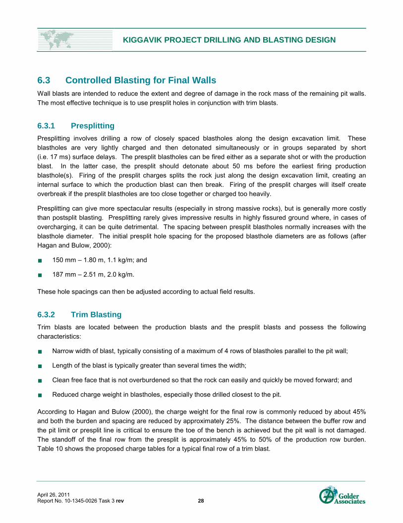
Table 10: Charge Table – Kiggavik Open Pits Trim Blasts....................................................................................................... 29
Table 11: Kiggavik Fragmentation Size Assessment (Emulsion/AN - 70/30) ........................................................................... 34
Table 12: Relative Drill and Blast Costs ................................................................................................................................... 36
Table 13: Estimated PPV for Water Bodies near the Proposed Kiggavik Pits .......................................................................... 38
Table 14: Typical Values for Substrate Density and Compression Wave Velocity ................................................................... 39
Table 15: Properties Used to Assess Setback Distance for Instantaneous Overpressure ....................................................... 40
Table 16: Minimum Setback Distance for Instantaneous Overpressure Guideline ................................................................... 40
Table 17: Estimated PPV at Selected Infrastructure Facilities Induced by Main, Centre and East Zone Blasts....................... 42
Table 18: Estimated PPV at Selected Infrastructure Facilities Induced by Andrew Lake Zone Blasts ..................................... 42
Table 19: Estimated PPV at the Andrew Lake Dewatering Structure ....................................................................................... 43
Table 20: Summary of Flyrock Ranges for Proposed Production Blast Designs ...................................................................... 44
Table 21: Summary of Estimated Nitrogen Loss for Kiggavik .................................................................................................. 48
Table 22: Summary of Estimated Nitrogen Loss for Andrew Lake ........................................................................................... 49
Table 23: Summary of Estimated Nitrogen Loss for End Grid .................................................................................................. 49
Table 24: Total Ammonia Concentrations in Mine Water from Case Studies ........................................................................... 51
FIGURES
Figure 1: General Site Location Map .......................................................................................................................................... 6
Figure 2: Site Map ...................................................................................................................................................................... 7
Figure 3: Regional Geology and Structure ............................................................................................................................... 10
Figure 4: Leaching Rates of Doped Emulsion Blends .............................................................................................................. 18
Figure 5: Quantity-Distance Plot for Storing Explosives ........................................................................................................... 19
Figure 6: Proposed Kiggavik Production Blast Design with 150 mm Diameter Holes .............................................................. 26
Figure 7: Proposed Kiggavik Production Blast Design with 187 mm Diameter Holes .............................................................. 27
KIGGAVIK PROJECT DRILLING AND BLASTING DESIGN
April 26, 2011 Report No. 10-1345-0026 Task 3 rev iv
Figure 8: Proposed Kiggavik Presplit Blast Design .................................................................................................................. 30
Figure 9: Proposed Kiggavik Trim Blast Design with 150 mm Diameter Holes ........................................................................ 31
Figure 10: Proposed Kiggavik Trim Blast Design with 187 mm Diameter Holes ...................................................................... 32
Figure 11: Fragmentation Size Distribution for the Kiggavik Main and Centre Pits .................................................................. 33
Figure 12: Fragmentation Size Distribution for the Kiggavik Andrew Lake Pit.......................................................................... 34
Figure 13: Blast Cost Comparison for Three Production Blast Designs ................................................................................... 35
Figure 14: Ground Vibration Attenuation Results from Various Studies ................................................................................... 37
Figure 15: Estimated PPV at a Given Distance for 150 mm and 187 mm Diameter Holes and Showing Various Vibration Limits ........................................................................................................................................................ 37
Figure 16: Charge Weight versus Setback Distance for Instantaneous Water Overpressure .................................................. 41
Figure 17: Estimated Yearly Nitrogen Loss for Kiggavik, Andrew Lake and End Grid ............................................................. 48
APPENDICES
APPENDIX A Canadian Explosives Regulations
APPENDIX B Nunavut Mine Health Safety Regulations
APPENDIX C DFO Comments on the Draft Environmental Impact Statement for the Proposed Kiggavik Project
APPENDIX D Current Site Plans (Provided by AREVA)

KIGGAVIK PROJECT DRILLING AND BLASTING DESIGN
April 26, 2011 Report No. 10-1345-0026 Task 3 rev 5
1.0 INTRODUCTION AREVA Resources Canada Inc. (AREVA) has retained Golder Associates Ltd. (Golder) to assess drilling and
blasting design for the proposed Kiggavik Project in Nunavut Territory.
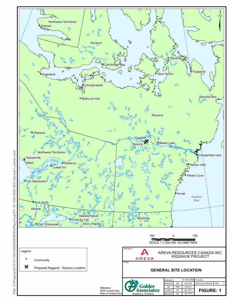
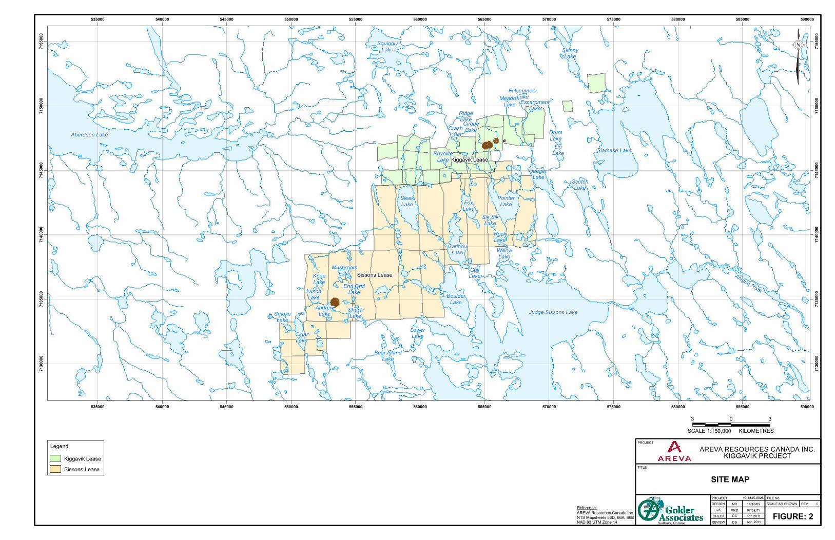
The Kiggavik property is situated approximately 80 km west of Baker Lake, Nunavut (Figure 1). The Kiggavik
Project can be divided into two main deposit areas: the Kiggavik area; and the Sissons area. Main, Centre and
East Zone deposits are located within the Kiggavik area, while the Andrew Lake and End Grid deposits are
located within the Sissons area, approximately 15 km to 17 km south of the Kiggavik area, as shown on
Figure 2.
The scope of work for this task is as follows:
Review Golder’s geotechnical database and summarize the existing geomechanical properties as they
relate to blasting.
Review AREVA’s initially anticipated mine design parameters as well as available drilling and excavating
equipment.
Review the vibration, flyrock, fragmentation and water overpressure limitations set by regulatory agencies
or internally by AREVA.
Provide blast design criteria on the basis of the engineering geological model, available equipment, and
required end-product from the blasting.
Provide a comparative assessment of the available explosives (e.g. ANFO, Emulsion and Emulsion/AN
blends). This will entail a trade-off assessment considering issues such as explosive and drilling costs as
well as potential environmental impacts.
Provide a review of issues related to the loss of nitrate, nitrite and ammonia associated blasting and provide
a blast management plan intended to mitigate such losses.
FILE No.SCALE AS SHOWN
FIGURE: 1REV. 0
ÇÇÇ
Nunavut
Alberta
Manitoba
Northwest Territories
Saskatchewan
Nunavut
Northwest Territories
HudsonBay
Detah
Arviat
Holman
Wekwetì
Kugaaruk
Taloyoak
Reliance
Fox Lake
Kugluktuk
Churchill
Whale Cove
Gjoa Haven
Fort Smith
Pine Point
Baker Lake
Repulse Bay
Umingmaktok
Yellowknife
Lutsel K'e
Fond-du-Lac
Lac Brochet
Rankin Inlet
Stony Rapids
Garden Creek
Coral Harbour
Cambridge Bay
Bathurst Inlet
Fort Chipewyan
Fort Resolution
Chesterfield Inlet
KiggavikSissons
PROJECT
TITLE
PROJECT
GISCHECKREVIEWSudbury, Ontario
RRD 07/02/11
10-1345-0026
KILOMETRESSCALE 1:7,500,000150 1500
Legend
CommunityÇ Proposed Kiggavik - Sissons Location
ReferenceESRI Canada DataAtlas of Canada Data
DCDS Apr. 2011
Apr. 2011
Path:
Z:\Pr
ojects
\2010
\10-13
45-00
26\G
IS\M
XDs\R
eport
ing\G
TI-10
-1345
-0026
-GEO
-Gen
eral L
ocati
on.m
xd
MDDESIGN 09/10/09
GENERAL SITE LOCATION
AREVA RESOURCES CANADA INC.KIGGAVIK PROJECT
AREVA RESOURCES CANADA INC.KIGGAVIK PROJECT
FILE No.SCALE AS SHOWN
FIGURE: 2REV. 0
PROJECT
TITLE
PROJECT DESIGN
GISCHECK
SITE MAP
REVIEWSudbury, Ontario
RRD 07/02/11
10-1345-0026
LinLake
CalfLakeKnee
Lake
RockLake
DrumLake
SmokeLake
CrashLake
ShackLake
LunchLake
CigarLake
FoxLake
AndrewLake
MeadowLake
WillowLake
JaegerLake Scotch
Lake
SkinnyLake
LowerLake
BoulderLake
CaribouLake
SleekLake
RidgeLake
PointerLake
Siamese LakeRhyoliteLake
MushroomLake
End GridLake
CirqueLake
SquigglyLake
Aberdeen Lake
Aniguq River
Sik SikLake
EscarpmentLake
Bear IslandLake
FelsenmeerLake
Judge Sissons Lake
Sissons Lease
Kiggavik Lease
535000
535000
540000
540000
545000
545000
550000
550000
555000
555000
560000
560000
565000
565000
570000
570000
575000
575000
580000
580000
585000
585000
590000
590000
7130
000
7130
000
7135
000
7135
000
7140
000
7140
000
7145
000
7145
000
7150
000
7150
000
7155
000
7155
000
LegendKiggavik LeaseSissons Lease
3 30SCALE 1:150,000 KILOMETRES
Reference:AREVA Resources Canada Inc.NTS Mapsheets 56D, 66A, 66BNAD 83 UTM Zone 14
DCDS Apr. 2011
Apr. 2011
MD 14/10/09

KIGGAVIK PROJECT DRILLING AND BLASTING DESIGN
April 26, 2011 Report No. 10-1345-0026 Task 3 rev 8
2.0 GEOTECHNICAL AND GEOMECHANICAL SUMMARY
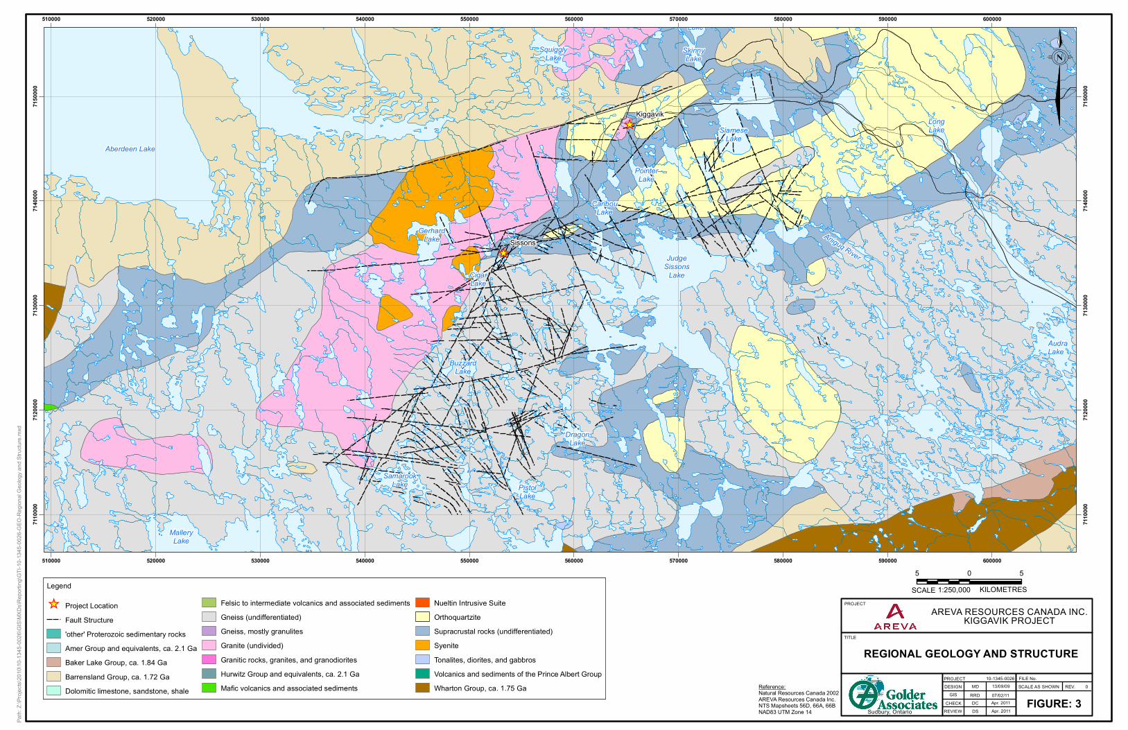
2.1 General Geology The Kiggavik Project is located within the Rae Province (AREVA, 2007), at the southwest end of the Archean
Woodburn Group, and at the northeastern end of the Thelon Basin which formed after the Hudsonian Orogeny
(Golder, 1989). The Woodburn group consists of metavolcanic and metasedimentary assemblages, which are in
tectonic contact and structurally overlie Archean basement granitic to minor amphibolitic gneisses
(AREVA, 2007), while the Thelon Sandstone unconformably overlies a series of geological units ranging from
Archean Basement to Aphebian rocks of various metamorphic grades (Golder, 1989). A regional geological map
is presented on Figure 3.
Overlying the Woodburn Group is the Meso-Proterozoic Dubwant Supergroup (AREVA, 2007). The Dubwant
Supergroup can be subdivided into the Baker Lake, Wharton and Barrensland Groups, in ascending order. The
Baker Lake Group consists of several sedimentary redbeds which are not exposed near the Kiggavik area, as
well as the Christopher Island Formation, which may have intrusive equivalents present as syentic dikes within
the Sissons area. The Wharton Group unconformably overlies the Baker Lake Group, and consists of the felsic
volcanic Pitz Formation and fluorite-bearing granite (AREVA, 2007). The Pitz Formation is not present in the
Sissons area, and the fluorite-bearing granite has been locally named the Lone Gull Granite. The Lone Gull
Granite has been interpreted to be older than the Wharton Group. The Barrensland Group unconformably
overlies the Wharton Group (AREVA, 2007). It mainly consists of the Thelon Formation, which is exposed to the
north of the Sissons area, and the MacKenzie diabase dikes, which are the youngest rocks within the project
area.
2.2 Kiggavik Area Deposits The Kiggavik area is located between two regional fault zones (AREVA, 2007). The Thelon fault is located to the
north, while the Sissons fault is located to the south. The Kiggavik deposits (Main, Centre and East Zones)
follow a local 65° east-northeast trending shear zone (Figure 3). Basement host rocks are composed of
metasediments (mainly metaarkoses and metapelites overlain by orthoquartzites), and to a lesser extent altered
granite and intrusives. Despite their considerable metamorphic overprint, these rocks appear to be essentially
flat lying with the foliation/bedding dipping north at 10° to 20° (Golder, 1989).
The lithology in the Main Zone deposit consists of granite and metasediments, with the near vertical fault serving
as the contact between the two units. At Main Zone, a northwest-southeast trending dike of MacKenzie diabase
cuts through the middle of the deposit, and is unmineralized (AREVA, 2007).
Main Zone consists of two parallel running major lenses, which are elongated along strike (AREVA, 2007) and
are approximately 20 m to 30 m thick, as well as two minor lenses. The major lenses trend east-northeast with a
plunge of approximately 25°, and are controlled by the intersection of the shear zone with a near vertical
northeast trending fault. Generally, mineralization at Main Zone occurs to depth of approximately 150 m to
190 m below ground surface (mbgs). Mineralized zones are associated with an intensive alteration halo,
characterized by desilicification and argillization with mainly illite and sericite.

KIGGAVIK PROJECT DRILLING AND BLASTING DESIGN
April 26, 2011 Report No. 10-1345-0026 Task 3 rev 9
Centre Zone is located approximately 600 m to the east of Main Zone, along strike of the shear zone
(AREVA, 2007). Mineralization occurs in two lenses with a shallow depth, extending to a depth of approximately
100 m below ground surface. The footwall rock consists of an orthoquartzite horizon, which controls the dip of
the mineralized lenses.
East Zone is located approximately 500 m to the east of Centre Zone, along strike of the shear zone
(AREVA, 2007). Mineralization within the East Zone is similar to that of Centre Zone, and occurs up to 60 mbgs.
2.3 Sissons Area Deposits The Sissons deposits are located in pelite and arenitic metasediments overlying granitic gneisses and
granodiorites (AREVA, 2007). These formations have been strongly metamorphosed and altered, tectonised,
and intruded by lamprophyres, syenites and granites. The rocks have gently dipping foliation, small scale
recumbent folding and low angle thrusting. The area also consists of steeply dipping brittle deformation zones
that trend east-northeast to north-northeast as a conjugate set. Three main faults (the Sissons North, Buzzard
Lake and Andrew Lake) intersect the area.
The Andrew Lake deposit is located on a major east-northeast structure (AREVA, 2007) (Figure 3). This region
has seen several episodes of hydraulic brecciation mainly within the granite and syenite rocks, and to a lesser
extent in the metasediment units. The subvertical faulting associated with the Andrew Lake deposit governs the
extension of the mineralization.
Three main mineralized lenses have been identified at Andrew Lake (AREVA, 2007). These are associated with
strongly altered metasediments (metagreywackes and metapelites), altered paragneiss, and less altered
metasediments. The lenses overlie each other, and are separated by a quartz breccia and paragneiss.
Mineralization within the Andrew Lake area occurs between 70 m and 270 m below ground surface.
The End Grid deposit is located approximately 960 m northeast of the Andrew Lake deposit. Although the
general geology is similar, the End Grid mineralization is located from 250 m to 450 m below surface. It has
significantly poorer rock quality than the Andrew Lake deposit. Only underground mining methods are
considered for the deposit.
AREVA RESOURCES CANADA INC.KIGGAVIK PROJECT
FILE No.SCALE AS SHOWN
FIGURE: 3REV. 0
PROJECT
TITLE
PROJECT DESIGN
GISCHECK
REGIONAL GEOLOGY AND STRUCTURE
REVIEWSudbury, Ontario
RRD 07/02/11
10-1345-0026
_̂
_̂
LongLake
CigarLake
SkinnyLake
DragonLake
PistolLake
SiameseLake
PointerLake
CaribouLake
GerhardLake
BuzzardLake
Aniguq River
AudraLake
Aberdeen Lake
SquigglyLake
SamarookLake
KavisilikLake
JudgeSissons
Lake
PrincessMaryLake
MalleryLake
Sissons
Kiggavik
510000
510000
520000
520000
530000
530000
540000
540000
550000
550000
560000
560000
570000
570000
580000
580000
590000
590000
600000
600000
7110
000
7110
000
7120
000
7120
000
7130
000
7130
000
7140
000
7140
000
7150
000
7150
000
Legend
_̂ Project LocationFault Structure'other' Proterozoic sedimentary rocksAmer Group and equivalents, ca. 2.1 GaBaker Lake Group, ca. 1.84 GaBarrensland Group, ca. 1.72 GaDolomitic limestone, sandstone, shale
Felsic to intermediate volcanics and associated sedimentsGneiss (undifferentiated)Gneiss, mostly granulitesGranite (undivided)Granitic rocks, granites, and granodioritesHurwitz Group and equivalents, ca. 2.1 GaMafic volcanics and associated sediments
Nueltin Intrusive SuiteOrthoquartziteSupracrustal rocks (undifferentiated)SyeniteTonalites, diorites, and gabbrosVolcanics and sediments of the Prince Albert GroupWharton Group, ca. 1.75 Ga
5 50SCALE 1:250,000 KILOMETRES
Reference:Natural Resources Canada 2002AREVA Resources Canada Inc.NTS Mapsheets 56D, 66A, 66BNAD83 UTM Zone 14
DCDS
Apr. 2011Apr. 2011
Path:
Z:\Pr
ojects
\2010
\10-13
45-00
26\G
IS\MX
Ds\Re
portin
g\GTI-
10-13
45-00
26-G
EO-R
egion
al Ge
ology
and S
tructu
re.mx
d
MD 13/09/09
KIGGAVIK PROJECT DRILLING AND BLASTING DESIGN
April 26, 2011 Report No. 10-1345-0026 Task 3 rev 11
2.4 Geotechnical Summary 2.4.1 Material Properties and Rock Mass Quality
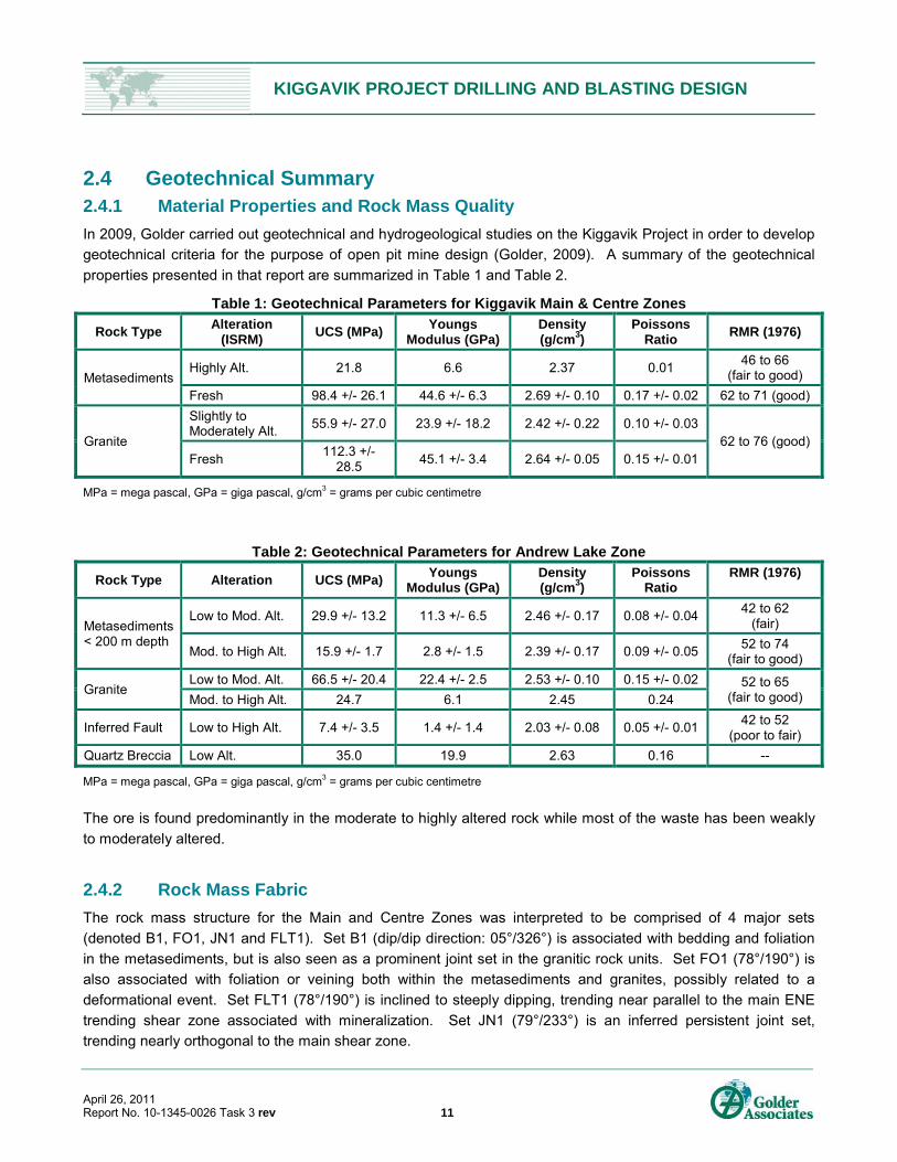
In 2009, Golder carried out geotechnical and hydrogeological studies on the Kiggavik Project in order to develop
geotechnical criteria for the purpose of open pit mine design (Golder, 2009). A summary of the geotechnical
properties presented in that report are summarized in Table 1 and Table 2.
Table 1: Geotechnical Parameters for Kiggavik Main & Centre Zones
Rock Type Alteration
(ISRM) UCS (MPa)
Youngs Modulus (GPa)
Density (g/cm3)
Poissons Ratio
RMR (1976)
Metasediments Highly Alt. 21.8 6.6 2.37 0.01
46 to 66 (fair to good)
Fresh 98.4 +/- 26.1 44.6 +/- 6.3 2.69 +/- 0.10 0.17 +/- 0.02 62 to 71 (good)
Granite
Slightly to Moderately Alt.
55.9 +/- 27.0 23.9 +/- 18.2 2.42 +/- 0.22 0.10 +/- 0.03 62 to 76 (good)
Fresh 112.3 +/-
28.5 45.1 +/- 3.4 2.64 +/- 0.05 0.15 +/- 0.01
MPa = mega pascal, GPa = giga pascal, g/cm3 = grams per cubic centimetre
Table 2: Geotechnical Parameters for Andrew Lake Zone
Rock Type Alteration UCS (MPa) Youngs
Modulus (GPa) Density (g/cm3)
Poissons Ratio
RMR (1976)
Metasediments < 200 m depth
Low to Mod. Alt. 29.9 +/- 13.2 11.3 +/- 6.5 2.46 +/- 0.17 0.08 +/- 0.04 42 to 62
(fair)
Mod. to High Alt. 15.9 +/- 1.7 2.8 +/- 1.5 2.39 +/- 0.17 0.09 +/- 0.05 52 to 74
(fair to good)
Granite Low to Mod. Alt. 66.5 +/- 20.4 22.4 +/- 2.5 2.53 +/- 0.10 0.15 +/- 0.02 52 to 65
(fair to good) Mod. to High Alt. 24.7 6.1 2.45 0.24
Inferred Fault Low to High Alt. 7.4 +/- 3.5 1.4 +/- 1.4 2.03 +/- 0.08 0.05 +/- 0.01 42 to 52
(poor to fair)
Quartz Breccia Low Alt. 35.0 19.9 2.63 0.16 --
MPa = mega pascal, GPa = giga pascal, g/cm3 = grams per cubic centimetre
The ore is found predominantly in the moderate to highly altered rock while most of the waste has been weakly
to moderately altered.
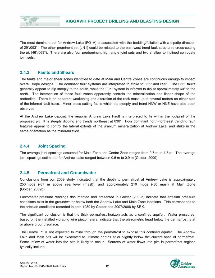
2.4.2 Rock Mass Fabric
The rock mass structure for the Main and Centre Zones was interpreted to be comprised of 4 major sets
(denoted B1, FO1, JN1 and FLT1). Set B1 (dip/dip direction: 05°/326°) is associated with bedding and foliation
in the metasediments, but is also seen as a prominent joint set in the granitic rock units. Set FO1 (78°/190°) is
also associated with foliation or veining both within the metasediments and granites, possibly related to a
deformational event. Set FLT1 (78°/190°) is inclined to steeply dipping, trending near parallel to the main ENE
trending shear zone associated with mineralization. Set JN1 (79°/233°) is an inferred persistent joint set,
trending nearly orthogonal to the main shear zone.
KIGGAVIK PROJECT DRILLING AND BLASTING DESIGN
April 26, 2011 Report No. 10-1345-0026 Task 3 rev 12
The most dominant set for Andrew Lake (FO1A) is associated with the bedding/foliation with a dip/dip direction
of 29°/093°. The other prominent set (JN1) could be related to the east-west trend fault structures cross-cutting
the pit (46°/063°). There are also four predominant high angle joint sets and two shallow to inclined conjugate
joint sets.
2.4.3 Faults and Shears
The faults and major shear zones identified to date at Main and Centre Zones are continuous enough to impact
overall slope designs. The dominant fault systems are interpreted to strike to 065° and 095°. The 065° faults
generally appear to dip steeply to the south, while the 095° system is inferred to dip at approximately 60° to the
north. The intersection of these fault zones apparently controls the mineralization and linear shape of the
orebodies. There is an apparent weakening and alteration of the rock mass up to several metres on either side
of the inferred fault trace. Minor cross-cutting faults which dip steeply and trend NNW or NNE have also been
observed.
At the Andrew Lake deposit, the regional Andrew Lake Fault is interpreted to lie within the footprint of the
proposed pit. It is steeply dipping and trends northeast at 030°. Four dominant north-northeast trending fault
features appear to control the lateral extents of the uranium mineralization at Andrew Lake, and strike in the
same orientation as the mineralization.
2.4.4 Joint Spacing
The average joint spacings assumed for Main Zone and Centre Zone ranged from 0.7 m to 4.3 m. The average
joint spacings estimated for Andrew Lake ranged between 0.5 m to 0.9 m (Golder, 2009).
2.4.5 Permafrost and Groundwater
Conclusions from our 2009 study indicated that the depth to permafrost at Andrew Lake is approximately
250 mbgs (-87 m above sea level (masl)), and approximately 210 mbgs (-30 masl) at Main Zone
(Golder, 2009b).
Piezometer pressure readings documented and presented in Golder (2009c) indicate that artesian pressure
conditions exist in the groundwater below both the Andrew Lake and Main Zone locations. This corresponds to
the artesian conditions recorded in both 1989 by Golder and 2007/2008 by SRK.
The significant conclusion is that the thick permafrost horizon acts as a confined aquifer. Water pressures,
based on the installed vibrating wire piezometers, indicate that the piezometric head below the permafrost is at
or above ground surface.
The Centre Pit is not expected to mine through the permafrost to expose this confined aquifer. The Andrew
Lake and Main pits will be excavated to ultimate depths at or slightly below the current base of permafrost.
Some inflow of water into the pits is likely to occur. Sources of water flows into pits in permafrost regions
typically include:

KIGGAVIK PROJECT DRILLING AND BLASTING DESIGN
April 26, 2011 Report No. 10-1345-0026 Task 3 rev 13
Seepage from melting of permafrost;
Seepage from unfrozen zones through pit walls;
Surface run-off and undiverted surface water; and
Sub-permafrost water.
3.0 MINE DESIGN PARAMETERS
3.1 Open Pit Mining 3.1.1 Open Pit Parameters
Table 3 provides a summary of the mine design parameters currently proposed for the Kiggavik deposits. The
pit sizes are based on the results of the 2007 Pre-feasibility Study and recent pit design studies.
Table 3: Mine Design Parameters for Kiggavik Deposits
Parameter East Zone Centre Zone Main Zone Andrew Lake
Pit Size (106 m3) 2.7 6.9 28.7 38.4
Pit Maximum Depth (m) ~120 ~110 ~255 ~275
Overall Pit Slope (o) 40 46 to 51 46 to 51 40 to 45
Bench Height (m) 12 (double bench) 12 (double bench) 12 (double bench) 12 (single bench)
Berm Width (m) 12 11 to 14 11 to 14 8
Bench Face Angle (o) 75 75 75 70 to 75
Ramp Width (m) 25 25 25 25
3.1.2 Drilling and Excavating Equipment
The following equipment is proposed for the drilling and blasting operations at Kiggavik:
Rotary blasthole drill with the following parameters:
Diesel powered, self propelled, crawler mounted;
187 mm diameter holes (a possible range of 150 mm to 229 mm);
Drill depths up to 45 m;
Penetration rate estimated at 14.5 m/hr for 150 mm diameter holes;
18 m3 hydraulic shovel for waste mining and a 10 m3 backhoe for ore mining; and
140 tonne trucks for waste hauling and 91 tonne trucks for ore hauling.
KIGGAVIK PROJECT DRILLING AND BLASTING DESIGN
April 26, 2011 Report No. 10-1345-0026 Task 3 rev 14
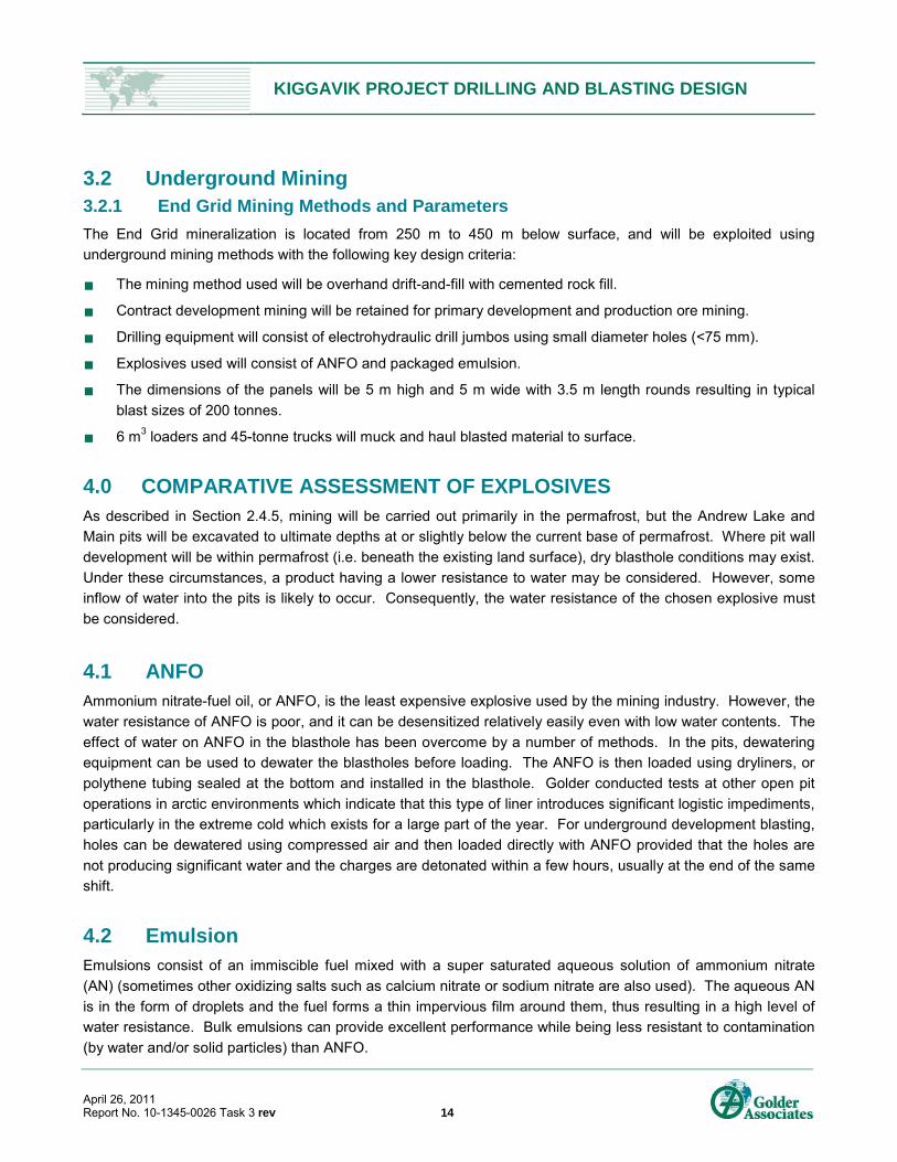
3.2 Underground Mining 3.2.1 End Grid Mining Methods and Parameters
The End Grid mineralization is located from 250 m to 450 m below surface, and will be exploited using
underground mining methods with the following key design criteria:
The mining method used will be overhand drift-and-fill with cemented rock fill.
Contract development mining will be retained for primary development and production ore mining.
Drilling equipment will consist of electrohydraulic drill jumbos using small diameter holes (<75 mm).
Explosives used will consist of ANFO and packaged emulsion.
The dimensions of the panels will be 5 m high and 5 m wide with 3.5 m length rounds resulting in typical
blast sizes of 200 tonnes.
6 m3 loaders and 45-tonne trucks will muck and haul blasted material to surface.
4.0 COMPARATIVE ASSESSMENT OF EXPLOSIVES As described in Section 2.4.5, mining will be carried out primarily in the permafrost, but the Andrew Lake and
Main pits will be excavated to ultimate depths at or slightly below the current base of permafrost. Where pit wall
development will be within permafrost (i.e. beneath the existing land surface), dry blasthole conditions may exist.
Under these circumstances, a product having a lower resistance to water may be considered. However, some
inflow of water into the pits is likely to occur. Consequently, the water resistance of the chosen explosive must
be considered.
4.1 ANFO Ammonium nitrate-fuel oil, or ANFO, is the least expensive explosive used by the mining industry. However, the
water resistance of ANFO is poor, and it can be desensitized relatively easily even with low water contents. The
effect of water on ANFO in the blasthole has been overcome by a number of methods. In the pits, dewatering
equipment can be used to dewater the blastholes before loading. The ANFO is then loaded using dryliners, or
polythene tubing sealed at the bottom and installed in the blasthole. Golder conducted tests at other open pit
operations in arctic environments which indicate that this type of liner introduces significant logistic impediments,
particularly in the extreme cold which exists for a large part of the year. For underground development blasting,
holes can be dewatered using compressed air and then loaded directly with ANFO provided that the holes are
not producing significant water and the charges are detonated within a few hours, usually at the end of the same
shift.
4.2 Emulsion Emulsions consist of an immiscible fuel mixed with a super saturated aqueous solution of ammonium nitrate
(AN) (sometimes other oxidizing salts such as calcium nitrate or sodium nitrate are also used). The aqueous AN
is in the form of droplets and the fuel forms a thin impervious film around them, thus resulting in a high level of
water resistance. Bulk emulsions can provide excellent performance while being less resistant to contamination
(by water and/or solid particles) than ANFO.
KIGGAVIK PROJECT DRILLING AND BLASTING DESIGN
April 26, 2011 Report No. 10-1345-0026 Task 3 rev 15
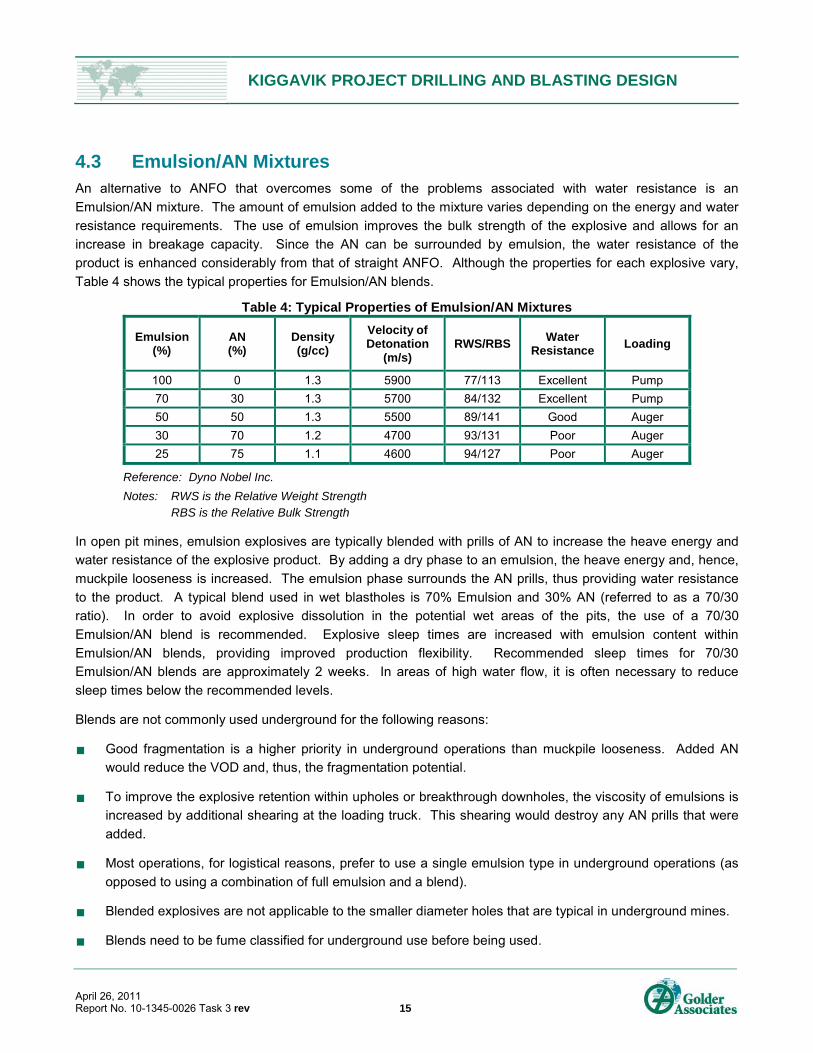
4.3 Emulsion/AN Mixtures An alternative to ANFO that overcomes some of the problems associated with water resistance is an
Emulsion/AN mixture. The amount of emulsion added to the mixture varies depending on the energy and water
resistance requirements. The use of emulsion improves the bulk strength of the explosive and allows for an
increase in breakage capacity. Since the AN can be surrounded by emulsion, the water resistance of the
product is enhanced considerably from that of straight ANFO. Although the properties for each explosive vary,
Table 4 shows the typical properties for Emulsion/AN blends.
Table 4: Typical Properties of Emulsion/AN Mixtures
Emulsion (%)
AN (%)
Density (g/cc)
Velocity of Detonation
(m/s) RWS/RBS
Water Resistance
Loading
100 0 1.3 5900 77/113 Excellent Pump
70 30 1.3 5700 84/132 Excellent Pump
50 50 1.3 5500 89/141 Good Auger
30 70 1.2 4700 93/131 Poor Auger
25 75 1.1 4600 94/127 Poor Auger
Reference: Dyno Nobel Inc.
Notes: RWS is the Relative Weight Strength RBS is the Relative Bulk Strength
In open pit mines, emulsion explosives are typically blended with prills of AN to increase the heave energy and
water resistance of the explosive product. By adding a dry phase to an emulsion, the heave energy and, hence,
muckpile looseness is increased. The emulsion phase surrounds the AN prills, thus providing water resistance
to the product. A typical blend used in wet blastholes is 70% Emulsion and 30% AN (referred to as a 70/30
ratio). In order to avoid explosive dissolution in the potential wet areas of the pits, the use of a 70/30
Emulsion/AN blend is recommended. Explosive sleep times are increased with emulsion content within
Emulsion/AN blends, providing improved production flexibility. Recommended sleep times for 70/30
Emulsion/AN blends are approximately 2 weeks. In areas of high water flow, it is often necessary to reduce
sleep times below the recommended levels.
Blends are not commonly used underground for the following reasons:
Good fragmentation is a higher priority in underground operations than muckpile looseness. Added AN
would reduce the VOD and, thus, the fragmentation potential.
To improve the explosive retention within upholes or breakthrough downholes, the viscosity of emulsions is
increased by additional shearing at the loading truck. This shearing would destroy any AN prills that were
added.
Most operations, for logistical reasons, prefer to use a single emulsion type in underground operations (as
opposed to using a combination of full emulsion and a blend).
Blended explosives are not applicable to the smaller diameter holes that are typical in underground mines.
Blends need to be fume classified for underground use before being used.
KIGGAVIK PROJECT DRILLING AND BLASTING DESIGN
April 26, 2011 Report No. 10-1345-0026 Task 3 rev 16
Thus, in wet conditions where ANFO cannot be used underground at the End Grid Mine, a 100% packaged
emulsion explosive is recommended.
4.4 Explosive Costs In general, the weight cost of ANFO, Emulsion and Emulsion/AN blends increases with the percent increase in
Emulsion. However, it is difficult to quantify the difference without detailed knowledge of the manufacturer, the
proposed plans for the site and the sources of components by a given manufacturer. Specific and relative costs
vary based on geographic as well as infrastructure parameters such as:
Sources for the products and/or components sourced; and
Conditions that affect the costs of the explosives at the site including:
Transportation;
Storage;
Manufacturer and/or preparation; and
External market cost pressures for the raw materials.
Although each manufacturer may have different costs for the various explosives, estimated explosives costs are
as follows:
ANFO $72.50/100 kg
70/30 Emulsion/AN Blend $97.80/100 kg
Although, ANFO is generally the least expensive explosive product, the total cost of drilling and blasting must be
considered when comparing options. This is because ANFO is also a less energetic explosive and requires a
smaller blast pattern in order to achieve fragmentation results comparable to the denser, higher energy emulsion
blends. Drilling costs are typically around 50% of total drill and blast costs. A cost comparison for the proposed
blast designs is provided in Section 6.4.
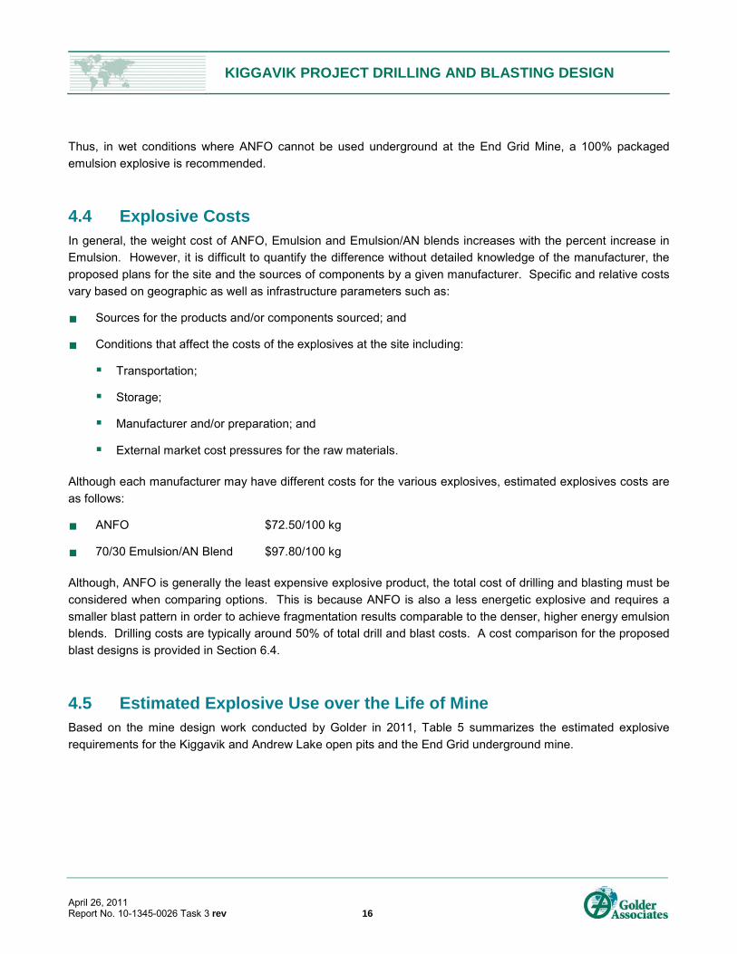
4.5 Estimated Explosive Use over the Life of Mine Based on the mine design work conducted by Golder in 2011, Table 5 summarizes the estimated explosive
requirements for the Kiggavik and Andrew Lake open pits and the End Grid underground mine.
KIGGAVIK PROJECT DRILLING AND BLASTING DESIGN
April 26, 2011 Report No. 10-1345-0026 Task 3 rev 17
Table 5: Summary of Estimated Explosive Use by Year
Year All Open Pits 70/30
Blend 1)
(tonnes)
Underground Mine ANFO 2) (tonnes)
1 231 0
2 7,693 0
3 7,331 40
4 7,645 237
5 6,823 372
6 6,808 426
7 6,771 770
8 1,998 819
9 1,677 814
10 1,529 841
11 1,540 793
12 731 556
13 311 125
Total 51,090 5,793
We understand that the explosives supplier will provide the AN and emulsion components. They will be
responsible for having it loaded on barges, transported to site and stored until required. The supplier will also
supply mixing and delivery trucks. Typically, the supplier is also responsible for delivering the blasting agents to
the blastholes. Mine personnel then charge the holes, place the detonators and primers and tie in the patterns.
The explosive supplier will be responsible for the design and construction of the ammonium nitrate storage area
and emulsion plant. It is estimated that the facility will contain a 40,000 kg capacity explosives magazine
(presplit powder and miscellaneous cartridge powder, primers and detonating cord), a magazine for blasting
accessories (detonators, wire, etc.), bulk storage silos or buildings (4,800 tonnes capacity) and a garage to
house explosives delivery vehicles.
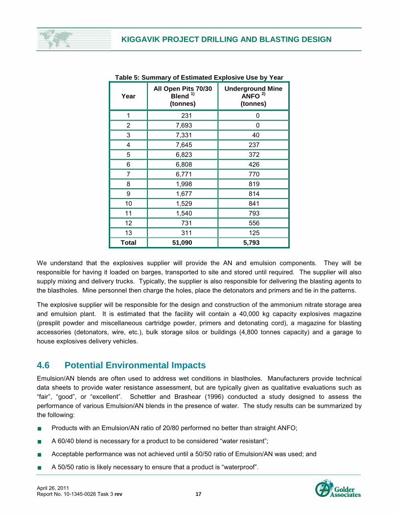
4.6 Potential Environmental Impacts Emulsion/AN blends are often used to address wet conditions in blastholes. Manufacturers provide technical
data sheets to provide water resistance assessment, but are typically given as qualitative evaluations such as
“fair”, “good”, or “excellent”. Schettler and Brashear (1996) conducted a study designed to assess the
performance of various Emulsion/AN blends in the presence of water. The study results can be summarized by
the following:
Products with an Emulsion/AN ratio of 20/80 performed no better than straight ANFO;
A 60/40 blend is necessary for a product to be considered “water resistant”;
Acceptable performance was not achieved until a 50/50 ratio of Emulsion/AN was used; and
A 50/50 ratio is likely necessary to ensure that a product is “waterproof”.
KIGGAVIK PROJECT DRILLING AND BLASTING DESIGN
April 26, 2011 Report No. 10-1345-0026 Task 3 rev 18
Figure 4 shows the estimated leach rates for Emulsion/AN blends. There is less than 0.5% difference in leach
rate above a 60/40 Emulsion/AN ratio (“water resistant” blend).
Figure 4: Leaching Rates of Doped Emulsion Blends
Pumpable blends have better water resistance than augerable blends which tend to lose their water resistance
as the percentage of emulsion decreases. In order to limit the water damage to the explosive, which would
result in poor blast performance, a doped emulsion of 70/30 (Emulsion/AN) blend is recommended.
5.0 BLAST IMPACT LIMITATIONS
5.1 Regulatory Limits 5.1.1 Explosives Regulations
The Canadian Regulations for the storage, possession, transportation, destruction and sale of blasting
explosives and initiation systems is contained in Appendix A. The following is an excerpt from Section 2.2 of that
document entitled Magazine Location:
A magazine should be situated so that the accidental explosion of its contents is not likely to cause any
serious damage to other buildings or injury to persons. The minimum distances by which a magazine
must be separated from other buildings or places are dependent on the maximum quantity of explosives
stored in the magazine at any one time. In Canada, the Quantity-Distance Table, compiled from a study
of the effects of recorded explosions, are taken as a guide in approving the site for a magazine containing
given amounts and types of explosives.
It is emphasized that these are minimum distances. Greater distances should be observed wherever
possible and greater distances in specific cases may be mandatory. Refer to Appendix A for a summary
of the Quantity-Distance Table.
0.00
0.50
1.00
1.50
2.00
2.50
3.00
3.50
4.00
40 50 60 70 80 90 100
AN
Lea
ch R
ate
(% p
er d
ay)
% Emulsion in Blasting Agent
KIGGAVIK PROJECT DRILLING AND BLASTING DESIGN
April 26, 2011 Report No. 10-1345-0026 Task 3 rev 19
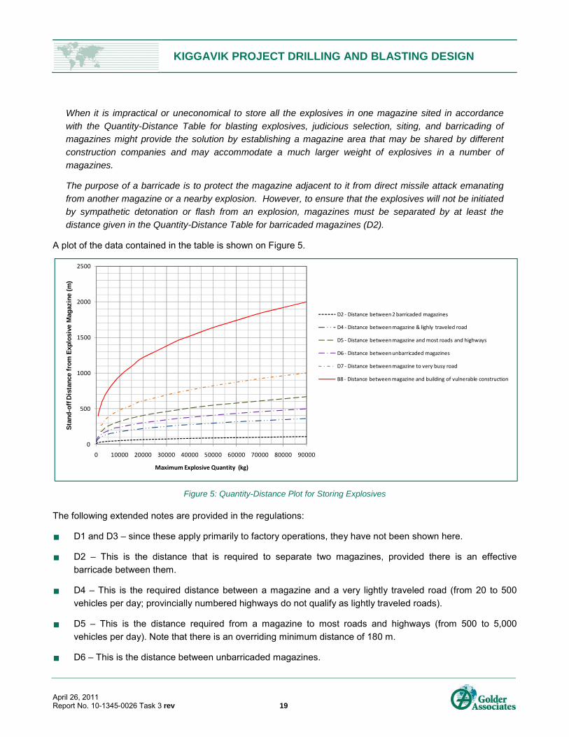
When it is impractical or uneconomical to store all the explosives in one magazine sited in accordance
with the Quantity-Distance Table for blasting explosives, judicious selection, siting, and barricading of
magazines might provide the solution by establishing a magazine area that may be shared by different
construction companies and may accommodate a much larger weight of explosives in a number of
magazines.
The purpose of a barricade is to protect the magazine adjacent to it from direct missile attack emanating
from another magazine or a nearby explosion. However, to ensure that the explosives will not be initiated
by sympathetic detonation or flash from an explosion, magazines must be separated by at least the
distance given in the Quantity-Distance Table for barricaded magazines (D2).
A plot of the data contained in the table is shown on Figure 5.
Figure 5: Quantity-Distance Plot for Storing Explosives
The following extended notes are provided in the regulations:
D1 and D3 – since these apply primarily to factory operations, they have not been shown here.
D2 – This is the distance that is required to separate two magazines, provided there is an effective
barricade between them.
D4 – This is the required distance between a magazine and a very lightly traveled road (from 20 to 500
vehicles per day; provincially numbered highways do not qualify as lightly traveled roads).
D5 – This is the distance required from a magazine to most roads and highways (from 500 to 5,000
vehicles per day). Note that there is an overriding minimum distance of 180 m.
D6 – This is the distance between unbarricaded magazines.
0
500
1000
1500
2000
2500
0 10000 20000 30000 40000 50000 60000 70000 80000 90000
Sta
nd
-off
Dis
tan
ce f
rom
Exp
losi
ve M
agaz
ine
(m)
Maximum Explosive Quantity (kg)
D2 ‐ Distance between 2 barricaded magazines
D4 ‐ Distance between magazine & lighly traveled road
D5 ‐ Distance between magazine and most roads and highways
D6 ‐ Distance between unbarricaded magazines
D7 ‐ Distance between magazine to very busy road
B8 ‐ Distance between magazine and building of vulnerable construction
KIGGAVIK PROJECT DRILLING AND BLASTING DESIGN
April 26, 2011 Report No. 10-1345-0026 Task 3 rev 20
D7 – This column is called Inhabited Building Distance. It applies to very busy roads (more than 5,000
vehicles in a 24-hour period) and to buildings where people may assemble. Note that there are minimum
distances: 270 m for up to 20 people and 400 m for more than 20 people.
D8 – This is the distance from a magazine to a building of vulnerable construction. Vulnerable construction
includes highrises, schools, hospitals, etc. Note that this is twice the normal Inhabited Building Distance
found in D7. There is an overriding distance of 400 m.
A copy of the Nunavut Mine Health Safety Regulations is contained in Appendix B. Section 14.06 states that:
Overhead power lines supplying electricity to a magazine or area where explosives are prepared shall
a) be protected against power surges and lighting; and
b) be terminated in a cable a minimum of 60 m horizontal distance from the magazine.
Section 14.08, subsection 2) states:
The ground surrounding a magazine must be kept free of all brush, timber or other combustible material
for a distance of not less than 20 m from the magazine (R-026-99, s.56).
5.1.2 Impact on Fisheries
Fisheries and Oceans Canada (DFO) has established a set of guidelines for the use of explosives in or near
Canadian fisheries waters (Wright and Hopky, 1998). These guidelines set out that “No explosive may be used
that produces or is likely to produce, a peak particle velocity greater than 13 mm/s in a spawning bed during egg
incubation”. Under conditions where these guidelines cannot be met, the proponent is required to prepare a
mitigation plan outlining additional procedures for protecting fish and their habitat. It is worth noting that this
guideline limit only applies during spawning season and only at spawning beds. The DFO guidelines also set
out an underwater overpressure limit of 100 kPa at fish habitat. The underwater overpressure limit only tends to
become a measurable indicator when blasting or explosives are used within the water body itself. No blasting is
expected to occur in any body of water on or around the Kiggavik Project site.
5.1.3 Nitrogen Compounds in Mine Effluent
Mines are subject to regulations limiting ammonia, nitrate and nitrite levels in mine effluents released into the
environment. Discharge limits are typically defined in consultation with the regulators based on legislated water
quality guidelines where they exist (e.g. metal mining effluent regulations (MMER), drinking water, aquatic life,
etc).
The ammonia limits in mine effluent in Nunavut are set by the water board in consultation with the proponent
(AREVA). The effluent limits are intended to allow the proponent to meet Canadian Environmental Quality
Guidelines (CCME) aquatic life guidelines in the receiving environment at a pre-determined location. The
receiving guidelines are as follows:
Total unionized ammonia 0.019 mg/L (this is dependent on water temperature); and
Total NO3-N = 13 mg/L.
KIGGAVIK PROJECT DRILLING AND BLASTING DESIGN
April 26, 2011 Report No. 10-1345-0026 Task 3 rev 21
The MMER does not have ammonia guidelines but states the undiluted effluent cannot be acutely toxic.
The preparation of an Ammonia Management Plan is typically part of the permitting process in Nunavut. This
plan would outline the measures that will be taken to minimize the release of Nitrogen compounds in effluent and
meet the suggested discharge limits.
5.2 Non-Regulatory Limits 5.2.1 Ground Vibrations
The intensity of ground vibrations, which is an elastic effect measured in units of PPV, is defined as the speed of
excitation of particles within the ground resulting from vibratory motion. For the purposes of this report, PPV is
measured in mm/s.
While ground vibration is an elastic effect, one must also consider the plastic or non-elastic effect produced
locally by each detonation when assessing the effects on the bedrock strata and local water wells. The
detonation of an explosive produces a very rapid and dramatic increase in volume due to the conversion of the
explosive from a solid to a gaseous state. When this occurs within the confines of a borehole, it has the
following effects:
The bedrock in the area immediately adjacent to the explosive product is crushed.
As the energy from the detonation radiates outward from the borehole, the bedrock between the borehole
and quarried face becomes fragmented and is displaced while there is minimal fracturing of the bedrock
behind the borehole.
Energy not used in the fracturing and displacement of the bedrock dissipates in the form of ground
vibrations, sound and airblast. This energy attenuates rapidly from the blast site due to geometric
spreading and natural damping.
Ground vibration guidelines are typically established for blasting sites to prevent damage to adjacent facilities or
infrastructure. Exceeding these levels does not in itself imply that damage has occurred but only increases the
potential that damage might occur. Siskind and Stagg (1993) suggested a PPV limit for Class B or better steel
pipelines (or Class 6 or better PVC pipelines) at 127 mm/s. However, many pipeline companies in Canada
(including TransCanada Pipelines and Union Gas) impose a more conservative limit of 50 mm/s. Ground
vibration limits for stronger materials, such as concrete, may be set as high as 150 to 200 mm/s, while peak
ground vibration levels of 300 to 600 mm/s are required to create micro-cracks or open existing discontinuities in
bedrock (Keil et al., 1977). Richards and Moore (2007) provided a review of the damage potential from blast-
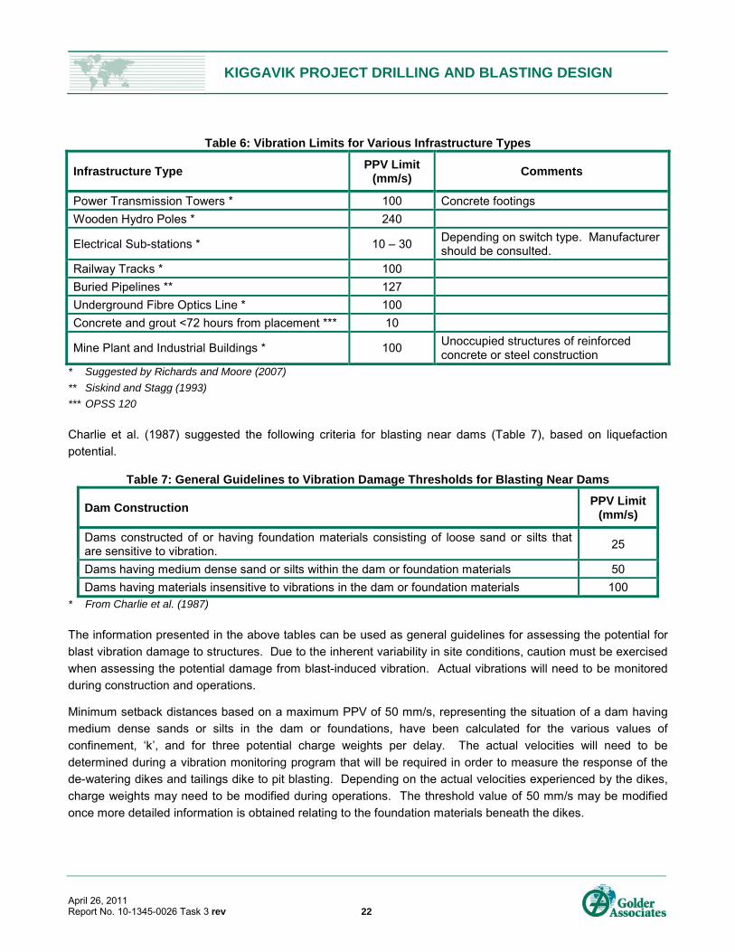
induced vibrations from open pit coal mines. Table 6 provides a summary of PPV limits proposed for a variety of
infrastructure types.
KIGGAVIK PROJECT DRILLING AND BLASTING DESIGN
April 26, 2011 Report No. 10-1345-0026 Task 3 rev 22
Table 6: Vibration Limits for Various Infrastructure Types
Infrastructure Type PPV Limit
(mm/s) Comments
Power Transmission Towers * 100 Concrete footings
Wooden Hydro Poles * 240
Electrical Sub-stations * 10 – 30 Depending on switch type. Manufacturer should be consulted.
Railway Tracks * 100
Buried Pipelines ** 127
Underground Fibre Optics Line * 100
Concrete and grout <72 hours from placement *** 10
Mine Plant and Industrial Buildings * 100 Unoccupied structures of reinforced concrete or steel construction
* Suggested by Richards and Moore (2007)
** Siskind and Stagg (1993)
*** OPSS 120
Charlie et al. (1987) suggested the following criteria for blasting near dams (Table 7), based on liquefaction
potential.
Table 7: General Guidelines to Vibration Damage Thresholds for Blasting Near Dams
Dam Construction PPV Limit
(mm/s)
Dams constructed of or having foundation materials consisting of loose sand or silts that are sensitive to vibration.
25
Dams having medium dense sand or silts within the dam or foundation materials 50
Dams having materials insensitive to vibrations in the dam or foundation materials 100 * From Charlie et al. (1987)
The information presented in the above tables can be used as general guidelines for assessing the potential for
blast vibration damage to structures. Due to the inherent variability in site conditions, caution must be exercised
when assessing the potential damage from blast-induced vibration. Actual vibrations will need to be monitored
during construction and operations.
Minimum setback distances based on a maximum PPV of 50 mm/s, representing the situation of a dam having
medium dense sands or silts in the dam or foundations, have been calculated for the various values of
confinement, ‘k’, and for three potential charge weights per delay. The actual velocities will need to be
determined during a vibration monitoring program that will be required in order to measure the response of the
de-watering dikes and tailings dike to pit blasting. Depending on the actual velocities experienced by the dikes,
charge weights may need to be modified during operations. The threshold value of 50 mm/s may be modified
once more detailed information is obtained relating to the foundation materials beneath the dikes.
KIGGAVIK PROJECT DRILLING AND BLASTING DESIGN
April 26, 2011 Report No. 10-1345-0026 Task 3 rev 23
5.2.2 Flyrock
Flyrock causes the most injuries and damage in reported blasting incidents at surface mines. It can be
considered as the ejection of rock fragments through the air or along the ground beyond the blast zone. It also
occurs when the explosive within the blasthole is either excessive or poorly confined and high pressure gas
propels broken rock fragments. Flyrock generally results from a mismatch between the available energy and the
work to be done. This results from either too much energy for a fixed burden or insufficient burden for a fixed
charge. Flyrock results from three key mechanisms (face bursting, cratering and rifling) which result from the
lack of confinement of the energy from the explosive column.
Flyrock should be limited from endangering the mine personnel as well as impacting the mine infrastructure.
The previously proposed blast clearance zone for the Kiggavik Project has been set at 500 m from final pit crest.
5.2.3 Fragmentation
In addition to designing blasts that minimize potential damage to the nearby structures, the design must also
ensure that the resulting blasted rock has a size distribution that complies with the mine’s requirements and
downstream processes such as crushing. We understand that the maximum fragmentation size for the Kiggavik
open pits is 1,000 mm. This is the assumed feed size to the crusher (i.e. ROM ore). Anything larger than this
will be caught in a grizzly and reduced with a rock breaker.
6.0 BLAST DESIGN The selection of an appropriate blasthole diameter is important in terms of fragmentation and cost. Ideally, it is
desirable to obtain the maximum fragmentation at a minimum cost. The cost of drilling and explosives
decreases as the diameter of the blasthole increases. Other factors must be considered such as bench height,
rock structure and rock hardness. Smaller diameter blastholes are more suited to strongly jointed rocks as the
decreased spacing results in fewer joints between holes. This will tend to reduce the amount of oversize and
result in better fragmentation. Blasthole sampling is another consideration when selecting the blasthole size.
Depending on the resource block model and type of mineralization, a tighter blasthole spacing can provide
additional sampling data for ore grade control. Some operations will use smaller diameter holes in ore blasts
and larger diameter holes in waste blasts.
As discussed in Section 3.1.2, the blasthole diameter considered in the 2007 PFS was 150 mm (6 in.) with the
capability of drilling larger diameter blastholes. Alternative designs are presented here for larger blastholes of
187 mm (9 in.) diameter.
The underground blast designs for the End Grid deposit are not discussed in this section. Both underground
development and production blasting will be done by contract crews using typical drift development blasting
methods. Blast parameters such as hole size, cut design, hole spacing and trim blasting are expected to be
developed by the contractor.

KIGGAVIK PROJECT DRILLING AND BLASTING DESIGN
April 26, 2011 Report No. 10-1345-0026 Task 3 rev 24
6.1 Blast Design Assumptions The production blast design criteria were formulated on the basis of the engineering geological models for the
deposits. Basic assumptions used for the process were:
A doped emulsion will be used (70/30, Emulsion/AN) to address potentially wet blasting conditions.
The operating bench height will be 12 m.
The available equipment will be capable of drilling blasthole diameters ranging from 150 mm up to 229 mm.
The earlier studies based costs on a 150 mm diameter blasthole. We also propose an alternate blasthole
of 187 mm diameter in order reduce the number of blastholes required. This would result in less drills,
fewer drillers and lower costs.
A staggered pattern using millisecond delays and en echelon firing sequence, initiated from a corner, is
assumed. The inter-hole and inter-row are designed to provide an upright muckpile which is appropriate for
the limited mobility and good breakout force and reach of a hydraulic shovel (JMRC, 1996).
The length of the blasted block will be a minimum of twice the width, which will be between three and five
rows for production blasts.
The bench face angles will generally be steep, approximately 75°, and hence vertical blastholes have been
assumed. According to Hagan and Bulow (2000), a vertical back row will usually be satisfactory where the
designed final face is steeply dipping (>70°). Inclined blastholes could improve the consistency of the
burden and the efficiency of fragmentation; however, accuracy of drilling angled holes is difficult to achieve,
particularly with smaller diameter blastholes.
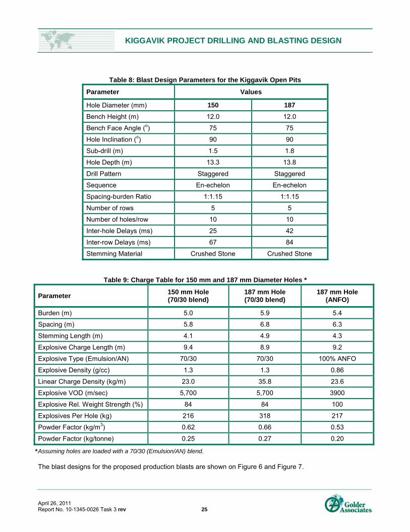
6.2 Production Blast Design Table 8 summarizes the blast designs considered for the Kiggavik open pits and are based on the geotechnical
properties for the Kiggavik site (Table 1). Table 9 shows the proposed charge tables for the proposed blast
designs.
KIGGAVIK PROJECT DRILLING AND BLASTING DESIGN
April 26, 2011 Report No. 10-1345-0026 Task 3 rev 25
Table 8: Blast Design Parameters for the Kiggavik Open Pits
Parameter Values
Hole Diameter (mm) 150 187
Bench Height (m) 12.0 12.0
Bench Face Angle (o) 75 75
Hole Inclination (o) 90 90
Sub-drill (m) 1.5 1.8
Hole Depth (m) 13.3 13.8
Drill Pattern Staggered Staggered
Sequence En-echelon En-echelon
Spacing-burden Ratio 1:1.15 1:1.15
Number of rows 5 5
Number of holes/row 10 10
Inter-hole Delays (ms) 25 42
Inter-row Delays (ms) 67 84
Stemming Material Crushed Stone Crushed Stone
Table 9: Charge Table for 150 mm and 187 mm Diameter Holes *
Parameter 150 mm Hole (70/30 blend)
187 mm Hole (70/30 blend)
187 mm Hole (ANFO)
Burden (m) 5.0 5.9 5.4
Spacing (m) 5.8 6.8 6.3
Stemming Length (m) 4.1 4.9 4.3
Explosive Charge Length (m) 9.4 8.9 9.2
Explosive Type (Emulsion/AN) 70/30 70/30 100% ANFO
Explosive Density (g/cc) 1.3 1.3 0.86
Linear Charge Density (kg/m) 23.0 35.8 23.6
Explosive VOD (m/sec) 5,700 5,700 3900
Explosive Rel. Weight Strength (%) 84 84 100
Explosives Per Hole (kg) 216 318 217
Powder Factor (kg/m3) 0.62 0.66 0.53
Powder Factor (kg/tonne) 0.25 0.27 0.20
* Assuming holes are loaded with a 70/30 (Emulsion/AN) blend.
The blast designs for the proposed production blasts are shown on Figure 6 and Figure 7.
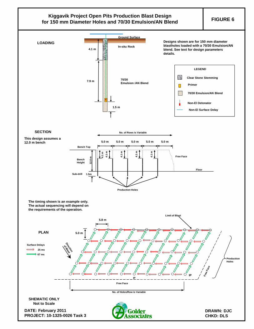
FIGURE 6Kiggavik Project Open Pits Production Blast Design
for 150 mm Diameter Holes and 70/30 Emulsion/AN Blend
4.1 m
7.9 m
1.5 m
In-situ Rock
Ground Surface
70/30 Emulsion /AN Blend
5.0 m 5.0 m5.0 m 5.0 m 5.0 m
4.1
m
12
.0 mBench
Height
Free Face
Bench Top
SECTION
LOADING Designs shown are for 150 mm diameter blastholes loaded with a 70/30 Emulsion/AN blend. See text for design parameters details.
Non-El Detonator
Non-El Surface Delay
LEGEND
70/30 Emulsion/AN Blend
Primer
Clear Stone Stemming
This design assumes a 12.0 m bench
No. of Rows is Variable
4.1
m
4.1
m
4.1
m
4.1
m
DATE: February 2011PROJECT: 10-1325-0026 Task 3
DRAWN: DJCCHKD: DLS
Limit of Blast
Free Face
No. of Holes/Row is Variable
1.5m
Production Holes
Floor
Production Holes
SHEMATIC ONLYNot to Scale
PLAN
Surface Delays
25 ms
67 ms
IP
5.8 m
5.0 m
Sub-drill
The timing shown is an example only. The actual sequencing will depend on the requirements of the operation.
IP
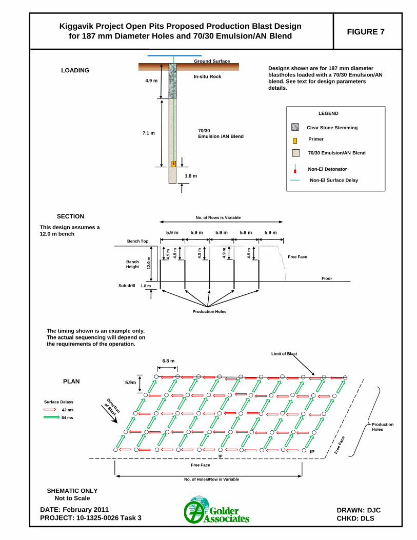
FIGURE 7Kiggavik Project Open Pits Proposed Production Blast Design
for 187 mm Diameter Holes and 70/30 Emulsion/AN Blend
4.9 m
7.1 m
1.8 m
In-situ Rock
Ground Surface
5.9 m 5.9 m5.9 m 5.9 m 5.9 m
4.9
m
12
.0 mBench
Height
Free Face
Bench Top
SECTION
LOADING Designs shown are for 187 mm diameter blastholes loaded with a 70/30 Emulsion/AN blend. See text for design parameters details.
Non-El Detonator
Non-El Surface Delay
LEGEND
70/30 Emulsion/AN Blend
Primer
Clear Stone Stemming
This design assumes a 12.0 m bench
No. of Rows is Variable
4.9
m
4.9
m
4.9
m
4.9
m
70/30 Emulsion /AN Blend
DATE: February 2011PROJECT: 10-1325-0026 Task 3
DRAWN: DJCCHKD: DLS
Limit of Blast
Free Face
No. of Holes/Row is Variable
1.8 m
Production Holes
Floor
Production Holes
SHEMATIC ONLYNot to Scale
PLAN
Surface Delays
42 ms
84 ms
IP
6.8 m
5.9m
Sub-drill
The timing shown is an example only. The actual sequencing will depend on the requirements of the operation.
IP
KIGGAVIK PROJECT DRILLING AND BLASTING DESIGN
April 26, 2011 Report No. 10-1345-0026 Task 3 rev 28
6.3 Controlled Blasting for Final Walls Wall blasts are intended to reduce the extent and degree of damage in the rock mass of the remaining pit walls.
The most effective technique is to use presplit holes in conjunction with trim blasts.
6.3.1 Presplitting
Presplitting involves drilling a row of closely spaced blastholes along the design excavation limit. These
blastholes are very lightly charged and then detonated simultaneously or in groups separated by short
(i.e. 17 ms) surface delays. The presplit blastholes can be fired either as a separate shot or with the production
blast. In the latter case, the presplit should detonate about 50 ms before the earliest firing production
blasthole(s). Firing of the presplit charges splits the rock just along the design excavation limit, creating an
internal surface to which the production blast can then break. Firing of the presplit charges will itself create
overbreak if the presplit blastholes are too close together or charged too heavily.
Presplitting can give more spectacular results (especially in strong massive rocks), but is generally more costly
than postsplit blasting. Presplitting rarely gives impressive results in highly fissured ground where, in cases of
overcharging, it can be quite detrimental. The spacing between presplit blastholes normally increases with the
blasthole diameter. The initial presplit hole spacing for the proposed blasthole diameters are as follows (after
Hagan and Bulow, 2000):
150 mm – 1.80 m, 1.1 kg/m; and
187 mm – 2.51 m, 2.0 kg/m.
These hole spacings can then be adjusted according to actual field results.
6.3.2 Trim Blasting
Trim blasts are located between the production blasts and the presplit blasts and possess the following
characteristics:
Narrow width of blast, typically consisting of a maximum of 4 rows of blastholes parallel to the pit wall;
Length of the blast is typically greater than several times the width;
Clean free face that is not overburdened so that the rock can easily and quickly be moved forward; and
Reduced charge weight in blastholes, especially those drilled closest to the pit.
According to Hagan and Bulow (2000), the charge weight for the final row is commonly reduced by about 45%
and both the burden and spacing are reduced by approximately 25%. The distance between the buffer row and
the pit limit or presplit line is critical to ensure the toe of the bench is achieved but the pit wall is not damaged.
The standoff of the final row from the presplit is approximately 45% to 50% of the production row burden.
Table 10 shows the proposed charge tables for a typical final row of a trim blast.
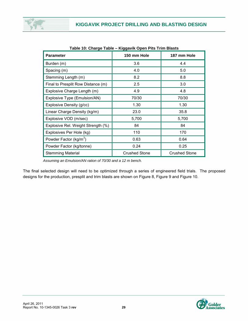
KIGGAVIK PROJECT DRILLING AND BLASTING DESIGN
April 26, 2011 Report No. 10-1345-0026 Task 3 rev 29
Table 10: Charge Table – Kiggavik Open Pits Trim Blasts
Parameter 150 mm Hole 187 mm Hole
Burden (m) 3.6 4.4
Spacing (m) 4.0 5.0
Stemming Length (m) 8.2 8.8
Final to Presplit Row Distance (m) 2.5 3.0
Explosive Charge Length (m) 4.9 4.8
Explosive Type (Emulsion/AN) 70/30 70/30
Explosive Density (g/cc) 1.30 1.30
Linear Charge Density (kg/m) 23.0 35.8
Explosive VOD (m/sec) 5,700 5,700
Explosive Rel. Weight Strength (%) 84 84
Explosives Per Hole (kg) 110 170
Powder Factor (kg/m3) 0.63 0.64
Powder Factor (kg/tonne) 0.24 0.25
Stemming Material Crushed Stone Crushed Stone
Assuming an Emulsion/AN ration of 70/30 and a 12 m bench.
The final selected design will need to be optimized through a series of engineered field trials. The proposed
designs for the production, presplit and trim blasts are shown on Figure 8, Figure 9 and Figure 10.
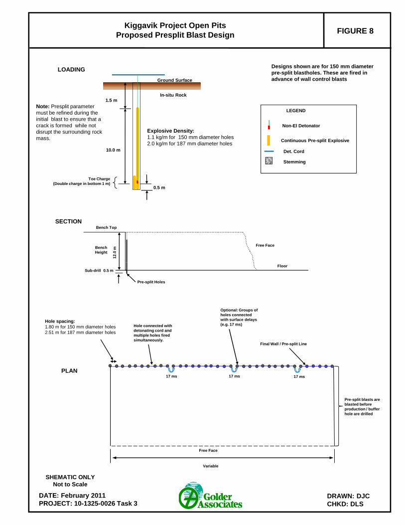
FIGURE 8Kiggavik Project Open Pits
Proposed Presplit Blast Design
1.5 m
10.0 m
In-situ Rock
Ground Surface
12
.0 mBench
Height
Free Face
Bench TopSECTION
LOADINGDesigns shown are for 150 mm diameter pre-split blastholes. These are fired in advance of wall control blasts
0.5 m
Toe Charge (Double charge in bottom 1 m)
Continuous Pre-split Explosive
Non-El Detonator
Det. Cord
LEGEND
Stemming
Note: Presplit parameter must be refined during the initial blast to ensure that a crack is formed while not disrupt the surrounding rock mass.
Explosive Density: 1.1 kg/m for 150 mm diameter holes2.0 kg/m for 187 mm diameter holes
DATE: February 2011PROJECT: 10-1325-0026 Task 3
DRAWN: DJCCHKD: DLS
Pre-split Holes
Floor
Final Wall / Pre-split Line
Free Face
Variable
Pre-split blasts are blasted before production / buffer hole are drilled
Hole spacing:1.80 m for 150 mm diameter holes2.51 m for 187 mm diameter holes
SHEMATIC ONLYNot to Scale
PLAN
Hole connected with detonating cord and multiple holes fired simultaneously.
0.5 mSub-drill
Optional: Groups of holes connected with surface delays (e.g. 17 ms)
17 ms 17 ms 17 ms
FIGURE 9Kiggavik Project Open Pits Trim Blast
for 150 mm Diameter Holes and 70/30 Emulsion/AN Blend
4.1 m
1.5 m
In-situ Rock
Ground Surface
PRODUCTION HOLES
8.2 m
1.1 m
In-situ Rock
Ground Surface
BUFFER ROW HOLES
4.1 m
12
.0 m
Bench Height
Free Face
Bench Top5.0 m3.6 m 5.0 m
Final Wall
2.5 m
8.2 m
SECTION
LOADING Designs shown are for 150 mm diameter blastholes loaded with a 70/30 Emulsion/AN blend.
Non-El Detonator
Non-El Surface Delay
LEGEND (Loading)
70/30 Emulsion/AN Blend
Primer
Stemming
7.9 m3.8 m
70/30 Emulsion /AN Blend70/30
Emulsion /AN Blend
DATE: February 2011PROJECT: 10-1325-0026 Task 3
DRAWN: DJCCHKD: DLS
Final Wall – Previously Blasted Pre-split
Free Face
Buffer Holes
Previously Blasted Pre-split
Floor
Production HolesBuffer Hole
1.5 m
Subdrill: 1.2m
SHEMATIC ONLYNot to Scale
PLAN
Surface Delays
25 ms
42 ms
67 ms
Buffer Hole
Production HoleIP
4.0 m
5.0 m
3.6 m
2.5 m
5.8 m
This is an example. The actual sequencing will depend on the requirements of the operation.
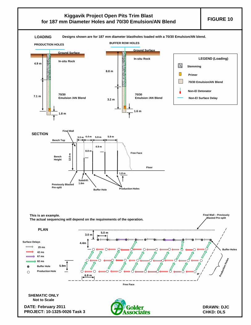
FIGURE 10Kiggavik Project Open Pits Trim Blast
for 187 mm Diameter Holes and 70/30 Emulsion/AN Blend
4.9 m
1.8 m
In-situ Rock
Ground Surface
PRODUCTION HOLES
8.8 m
1.6 m
In-situ Rock
Ground Surface
BUFFER ROW HOLES
4.9 m
12
.0 m
Bench Height
Free Face
Bench Top5.9 m4.4 m 5.9 m
Final Wall
3.0 m
8.8 m
SECTION
LOADING Designs shown are for 187 mm diameter blastholes loaded with a 70/30 Emulsion/AN blend.
Non-El Detonator
Non-El Surface Delay
LEGEND (Loading)
70/30 Emulsion/AN Blend
Primer
Stemming
7.1 m3.2 m
70/30 Emulsion /AN Blend
70/30 Emulsion /AN Blend
DATE: February 2011PROJECT: 10-1325-0026 Task 3
DRAWN: DJCCHKD: DLS
Final Wall – Previously Blasted Pre-split
Free Face
Buffer Holes
Previously Blasted Pre-split
Floor
Production HolesBuffer Hole
1.8 m
Subdrill: 1.6m
SHEMATIC ONLYNot to Scale
PLAN
Surface Delays
42 ms
67 ms
82 ms
Buffer Hole
Production HoleIP
5.0 m
5.9m
4.4m
3.0 m
6.8 m
This is an example. The actual sequencing will depend on the requirements of the operation.
25 ms

KIGGAVIK PROJECT DRILLING AND BLASTING DESIGN
April 26, 2011 Report No. 10-1345-0026 Task 3 rev 33
6.4 Fragmentation The most commonly used system to predict rock fragmentation in bench blasting with a single free face is the
Kuz-Ram fragmentation model. The Kuz-Ram model is an empirically derived predictor of size distribution for
blasting hard rock and does not include further breakdown during subsequent handling. The approach has been
found to provide a reliable estimate of the coarse end of the size distribution, but tends to underestimate the
proportion of fines at the smaller particle end of the distribution. The Kuz-Ram model takes into account the
blast layout, rock type, and the explosive used, although it does not allow for changes in the blast timing. It
incorporates the effects of burden, spacing, blasthole diameter, charge length and type, square or staggered
patterns, rock jointing and rock strength. Two key drawbacks to the Kuz-Ram Model are its poor predictive
capability in the fines range and upper limit cut-off to block sizes.
Because the Kuz-Ram model was developed based on empirical data, it provides guidelines and trends for
fragmentation prediction results but should not be considered as a precise predictor. Calibration of the model is
typically achieved by image analysis, which provides a quantitative measure of fragmentation based on image
analysis of muckpiles, run of mine (ROM) and crusher product.
The predicted fragmentation assumes a ratio of actual to theoretical VOD of 0.85, although this ratio could be as
high as 0.95 if the bulk product is well mixed. Plots of the estimated fragmentation size distributions for the blast
designs presented in Table 8 are displayed on Figure 11 and Figure 12. Since most of the blasts will be in waste
rock, the analyses were conducted for the waste blast designs at the two locations.
Figure 11: Fragmentation Size Distribution for the Kiggavik Main and Centre Pits
0%
10%
20%
30%
40%
50%
60%
70%
80%
90%
100%
1 10 100 1000
Percent Passing (%)
Size (mm)
187 mm Hole 70/30 Blend
150 mm Hole 70/30 Blend
187 mm Hole ANFO
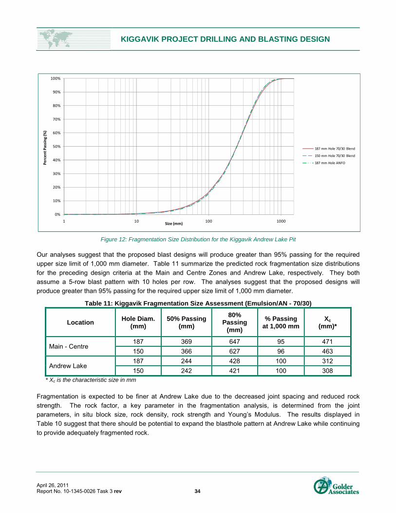
KIGGAVIK PROJECT DRILLING AND BLASTING DESIGN
April 26, 2011 Report No. 10-1345-0026 Task 3 rev 34
Figure 12: Fragmentation Size Distribution for the Kiggavik Andrew Lake Pit
Our analyses suggest that the proposed blast designs will produce greater than 95% passing for the required
upper size limit of 1,000 mm diameter. Table 11 summarize the predicted rock fragmentation size distributions
for the preceding design criteria at the Main and Centre Zones and Andrew Lake, respectively. They both
assume a 5-row blast pattern with 10 holes per row. The analyses suggest that the proposed designs will
produce greater than 95% passing for the required upper size limit of 1,000 mm diameter.
Table 11: Kiggavik Fragmentation Size Assessment (Emulsion/AN - 70/30)
Location Hole Diam.
(mm) 50% Passing
(mm)
80% Passing
(mm)
% Passing at 1,000 mm
Xc (mm)*
Main - Centre 187 369 647 95 471
150 366 627 96 463
Andrew Lake 187 244 428 100 312
150 242 421 100 308 * Xc is the characteristic size in mm
Fragmentation is expected to be finer at Andrew Lake due to the decreased joint spacing and reduced rock
strength. The rock factor, a key parameter in the fragmentation analysis, is determined from the joint
parameters, in situ block size, rock density, rock strength and Young’s Modulus. The results displayed in
Table 10 suggest that there should be potential to expand the blasthole pattern at Andrew Lake while continuing
to provide adequately fragmented rock.
0%
10%
20%
30%
40%
50%
60%
70%
80%
90%
100%
1 10 100 1000
Percent Passing (%)
Size (mm)
187 mm Hole 70/30 Blend
150 mm Hole 70/30 Blend
187 mm Hole ANFO
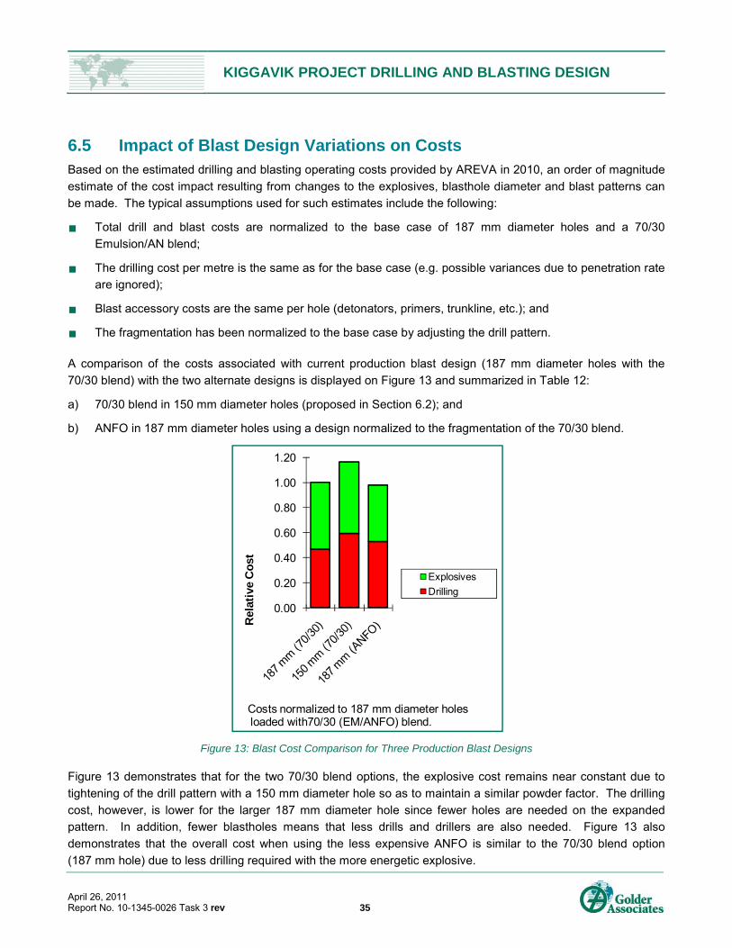
KIGGAVIK PROJECT DRILLING AND BLASTING DESIGN
April 26, 2011 Report No. 10-1345-0026 Task 3 rev 35
6.5 Impact of Blast Design Variations on Costs Based on the estimated drilling and blasting operating costs provided by AREVA in 2010, an order of magnitude
estimate of the cost impact resulting from changes to the explosives, blasthole diameter and blast patterns can
be made. The typical assumptions used for such estimates include the following:
Total drill and blast costs are normalized to the base case of 187 mm diameter holes and a 70/30
Emulsion/AN blend;
The drilling cost per metre is the same as for the base case (e.g. possible variances due to penetration rate
are ignored);
Blast accessory costs are the same per hole (detonators, primers, trunkline, etc.); and
The fragmentation has been normalized to the base case by adjusting the drill pattern.
A comparison of the costs associated with current production blast design (187 mm diameter holes with the
70/30 blend) with the two alternate designs is displayed on Figure 13 and summarized in Table 12:
a) 70/30 blend in 150 mm diameter holes (proposed in Section 6.2); and
b) ANFO in 187 mm diameter holes using a design normalized to the fragmentation of the 70/30 blend.
Figure 13: Blast Cost Comparison for Three Production Blast Designs
Figure 13 demonstrates that for the two 70/30 blend options, the explosive cost remains near constant due to
tightening of the drill pattern with a 150 mm diameter hole so as to maintain a similar powder factor. The drilling
cost, however, is lower for the larger 187 mm diameter hole since fewer holes are needed on the expanded
pattern. In addition, fewer blastholes means that less drills and drillers are also needed. Figure 13 also
demonstrates that the overall cost when using the less expensive ANFO is similar to the 70/30 blend option
(187 mm hole) due to less drilling required with the more energetic explosive.
0.00
0.20
0.40
0.60
0.80
1.00
1.20
Rel
ativ
e C
ost
Explosives
Drilling
Costs normalized to 187 mm diameter holesloaded with70/30 (EM/ANFO) blend.
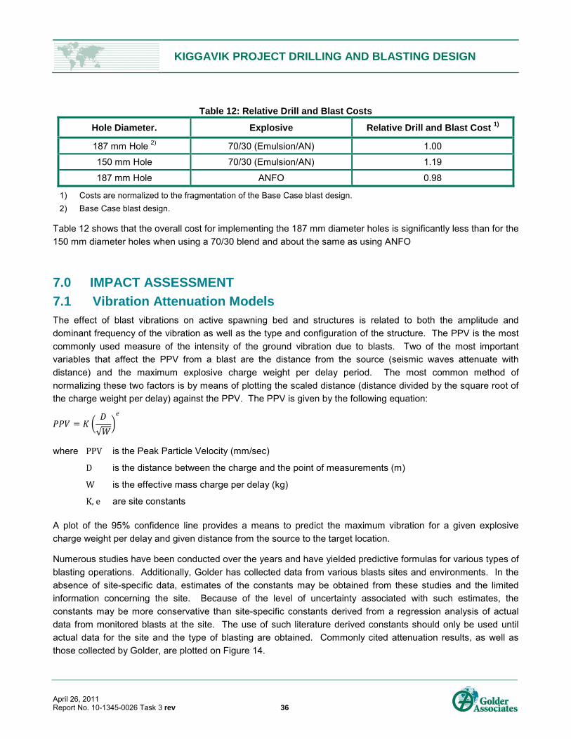
KIGGAVIK PROJECT DRILLING AND BLASTING DESIGN
April 26, 2011 Report No. 10-1345-0026 Task 3 rev 36
Table 12: Relative Drill and Blast Costs
Hole Diameter. Explosive Relative Drill and Blast Cost 1)
187 mm Hole 2) 70/30 (Emulsion/AN) 1.00
150 mm Hole 70/30 (Emulsion/AN) 1.19
187 mm Hole ANFO 0.98
1) Costs are normalized to the fragmentation of the Base Case blast design.
2) Base Case blast design.
Table 12 shows that the overall cost for implementing the 187 mm diameter holes is significantly less than for the
150 mm diameter holes when using a 70/30 blend and about the same as using ANFO
7.0 IMPACT ASSESSMENT
7.1 Vibration Attenuation Models The effect of blast vibrations on active spawning bed and structures is related to both the amplitude and
dominant frequency of the vibration as well as the type and configuration of the structure. The PPV is the most
commonly used measure of the intensity of the ground vibration due to blasts. Two of the most important
variables that affect the PPV from a blast are the distance from the source (seismic waves attenuate with
distance) and the maximum explosive charge weight per delay period. The most common method of
normalizing these two factors is by means of plotting the scaled distance (distance divided by the square root of
the charge weight per delay) against the PPV. The PPV is given by the following equation:
√
where PPV is the Peak Particle Velocity (mm/sec)
D is the distance between the charge and the point of measurements (m)
W is the effective mass charge per delay (kg)
K, e are site constants
A plot of the 95% confidence line provides a means to predict the maximum vibration for a given explosive
charge weight per delay and given distance from the source to the target location.
Numerous studies have been conducted over the years and have yielded predictive formulas for various types of
blasting operations. Additionally, Golder has collected data from various blasts sites and environments. In the
absence of site-specific data, estimates of the constants may be obtained from these studies and the limited
information concerning the site. Because of the level of uncertainty associated with such estimates, the
constants may be more conservative than site-specific constants derived from a regression analysis of actual
data from monitored blasts at the site. The use of such literature derived constants should only be used until
actual data for the site and the type of blasting are obtained. Commonly cited attenuation results, as well as
those collected by Golder, are plotted on Figure 14.

KIGGAVIK PROJECT DRILLING AND BLASTING DESIGN
April 26, 2011 Report No. 10-1345-0026 Task 3 rev 37
Figure 14: Ground Vibration Attenuation Results from Various Studies
Based on the initial information we have regarding the Kiggavik sites, the constants from the open pit in the NWT
(K value of 964 and an e value of -1.47) have been chosen until further substantial data from the site are
recorded. Figure 15 shows the estimated vibration amplitudes for the proposed designs using 150 mm and
187 mm diameter blastholes (70/30 Emulsion/AN blend).
Figure 15: Estimated PPV at a Given Distance for 150 mm and 187 mm Diameter Holes and
Showing Various Vibration Limits
1
10
100
1000
1 10 100
Pea
k P
arti
cle
Vel
oci
ty (
mm
/s)
Scaled Distance (m/kg1/2)
USBM typical upper limit (Oriard, 2002)
Open pit toward an open face (Scott, 1996)
Open pit in NWT (large data set)
Open pit in Quebec
Limestone quarries in Southern Ontario
PPV = 964*(SD)-1.47
95% ConfidenceOpen pit in NWT
PPV = 964*(SD)-1.47
95% ConfidenceOpen pit in NWT
0
50
100
150
200
250
50 100 150 200 250 300 350 400 450 500
Pae
k P
arti
cle
Vel
oci
ty (
mm
/s)
Distance (m)
187 mm hole
150 mm Hole
Uncured Concrete Limit (10 mm/s)
Spawning Bed Limit (13 mm/s)
Standard 50 mm/s Limit
100 mm/s Limit
Buried Pipeline Limit
Wooden Hydro Poles
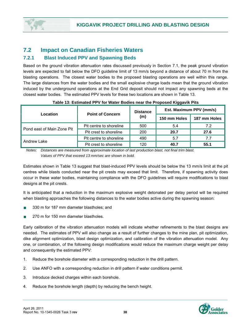
KIGGAVIK PROJECT DRILLING AND BLASTING DESIGN
April 26, 2011 Report No. 10-1345-0026 Task 3 rev 38
7.2 Impact on Canadian Fisheries Waters 7.2.1 Blast Induced PPV and Spawning Beds
Based on the ground vibration attenuation rates discussed previously in Section 7.1, the peak ground vibration
levels are expected to fall below the DFO guideline limit of 13 mm/s beyond a distance of about 70 m from the
blasting operations. The closest water bodies to the proposed blasting operations are well within this range.
The large distances from the water bodies and the small explosive charge loads mean that the ground vibration
induced by the underground operations at the End Grid deposit should not impact any spawning beds at the
closest water bodies. The estimated PPV levels for these two locations are shown in Table 13.
Table 13: Estimated PPV for Water Bodies near the Proposed Kiggavik Pits
Location Point of Concern Distance
(m)
Est. Maximum PPV (mm/s)
150 mm Holes 187 mm Holes
Pond east of Main Zone Pit Pit centre to shoreline 500 5.4 7.2
Pit crest to shoreline 200 20.7 27.6
Andrew Lake Pit centre to shoreline 490 5.7 7.7
Pit crest to shoreline 120 40.7 55.1 Notes: Distances are measured from approximate location of last production blast, not final trim blast.
Values of PPV that exceed 13 mm/sec are shown in bold.
Estimates shown in Table 13 suggest that blast-induced PPV levels should be below the 13 mm/s limit at the pit
centres while blasts conducted near the pit crests may exceed that limit. Therefore, if spawning activity does
occur in these water bodies, maintaining compliance with the DFO guidelines will require modifications to blast
designs at the pit crests.
It is anticipated that a reduction in the maximum explosive weight detonated per delay period will be required
when blasting approaches the following distances to the water bodies active during the spawning season:
330 m for 187 mm diameter blastholes; and
270 m for 150 mm diameter blastholes.
Early calibration of the vibration attenuation models will indicate whether refinements to the blast designs are
needed. The estimates of PPV will also change as a result of further changes to the mine plan, pit optimization,
dike alignment optimization, blast design optimization, and calibration of the vibration attenuation model. Any
one, or combination, of the following design modifications would reduce the maximum charge weight per delay
and consequently the estimated PPV:
1. Reduce the borehole diameter with a corresponding reduction in the drill pattern.
2. Use ANFO with a corresponding reduction in drill pattern if water conditions permit.
3. Introduce decked charges within each borehole.
4. Reduce the borehole length (depth) by reducing the bench height.
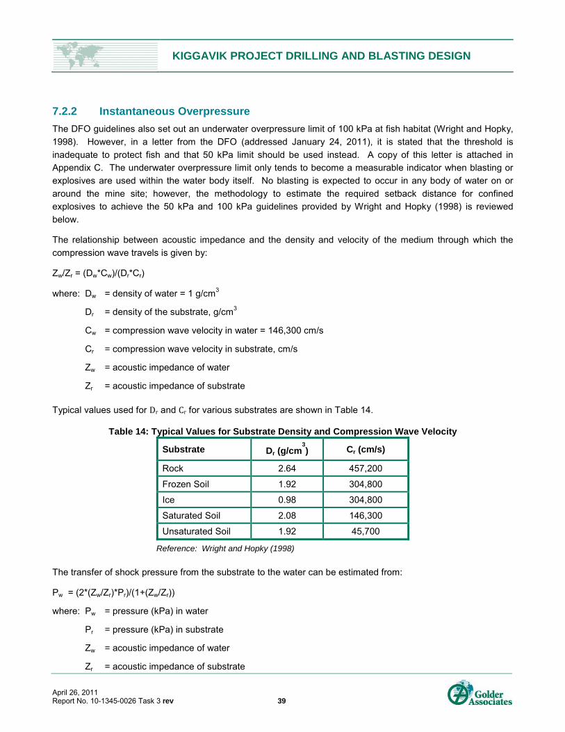
KIGGAVIK PROJECT DRILLING AND BLASTING DESIGN
April 26, 2011 Report No. 10-1345-0026 Task 3 rev 39
7.2.2 Instantaneous Overpressure
The DFO guidelines also set out an underwater overpressure limit of 100 kPa at fish habitat (Wright and Hopky,
1998). However, in a letter from the DFO (addressed January 24, 2011), it is stated that the threshold is
inadequate to protect fish and that 50 kPa limit should be used instead. A copy of this letter is attached in
Appendix C. The underwater overpressure limit only tends to become a measurable indicator when blasting or
explosives are used within the water body itself. No blasting is expected to occur in any body of water on or
around the mine site; however, the methodology to estimate the required setback distance for confined
explosives to achieve the 50 kPa and 100 kPa guidelines provided by Wright and Hopky (1998) is reviewed
below.
The relationship between acoustic impedance and the density and velocity of the medium through which the
compression wave travels is given by:
Zw/Zr = (Dw*Cw)/(Dr*Cr)
where: Dw = density of water = 1 g/cm3
Dr = density of the substrate, g/cm3
Cw = compression wave velocity in water = 146,300 cm/s
Cr = compression wave velocity in substrate, cm/s
Zw = acoustic impedance of water
Zr = acoustic impedance of substrate
Typical values used for Dr and Cr for various substrates are shown in Table 14.
Table 14: Typical Values for Substrate Density and Compression Wave Velocity
Substrate Dr (g/cm3) Cr (cm/s)
Rock 2.64 457,200
Frozen Soil 1.92 304,800
Ice 0.98 304,800
Saturated Soil 2.08 146,300
Unsaturated Soil 1.92 45,700
Reference: Wright and Hopky (1998)
The transfer of shock pressure from the substrate to the water can be estimated from:
Pw = (2*(Zw/Zr)*Pr)/(1+(Zw/Zr))
where: Pw = pressure (kPa) in water
Pr = pressure (kPa) in substrate
Zw = acoustic impedance of water
Zr = acoustic impedance of substrate
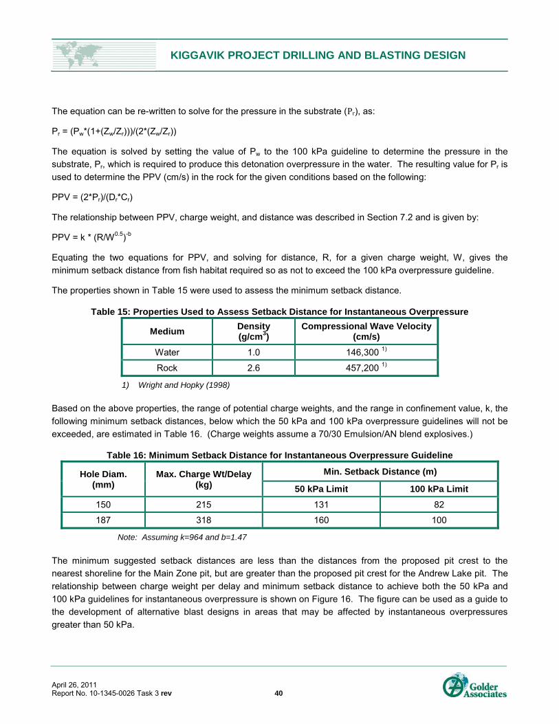
KIGGAVIK PROJECT DRILLING AND BLASTING DESIGN
April 26, 2011 Report No. 10-1345-0026 Task 3 rev 40
The equation can be re-written to solve for the pressure in the substrate (Pr), as:
Pr = (Pw*(1+(Zw/Zr)))/(2*(Zw/Zr))
The equation is solved by setting the value of Pw to the 100 kPa guideline to determine the pressure in the
substrate, Pr, which is required to produce this detonation overpressure in the water. The resulting value for Pr is
used to determine the PPV (cm/s) in the rock for the given conditions based on the following:
PPV = (2*Pr)/(Dr*Cr)
The relationship between PPV, charge weight, and distance was described in Section 7.2 and is given by:
PPV = k * (R/W0.5)-b
Equating the two equations for PPV, and solving for distance, R, for a given charge weight, W, gives the
minimum setback distance from fish habitat required so as not to exceed the 100 kPa overpressure guideline.
The properties shown in Table 15 were used to assess the minimum setback distance.
Table 15: Properties Used to Assess Setback Distance for Instantaneous Overpressure
Medium Density (g/cm3)
Compressional Wave Velocity (cm/s)
Water 1.0 146,300 1)
Rock 2.6 457,200 1)
1) Wright and Hopky (1998)
Based on the above properties, the range of potential charge weights, and the range in confinement value, k, the
following minimum setback distances, below which the 50 kPa and 100 kPa overpressure guidelines will not be
exceeded, are estimated in Table 16. (Charge weights assume a 70/30 Emulsion/AN blend explosives.)
Table 16: Minimum Setback Distance for Instantaneous Overpressure Guideline
Hole Diam. (mm)
Max. Charge Wt/Delay (kg)
Min. Setback Distance (m)
50 kPa Limit 100 kPa Limit
150 215 131 82
187 318 160 100
Note: Assuming k=964 and b=1.47
The minimum suggested setback distances are less than the distances from the proposed pit crest to the
nearest shoreline for the Main Zone pit, but are greater than the proposed pit crest for the Andrew Lake pit. The
relationship between charge weight per delay and minimum setback distance to achieve both the 50 kPa and
100 kPa guidelines for instantaneous overpressure is shown on Figure 16. The figure can be used as a guide to
the development of alternative blast designs in areas that may be affected by instantaneous overpressures
greater than 50 kPa.
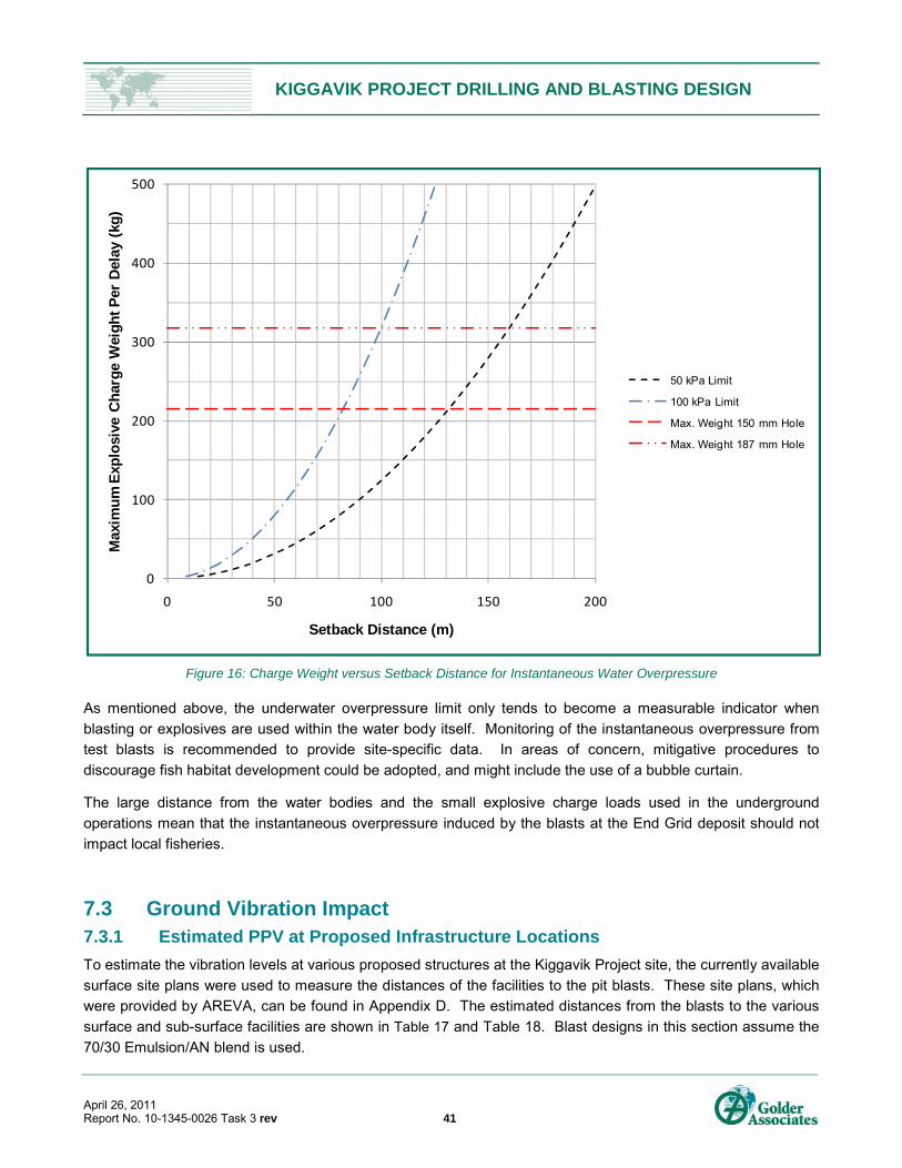
KIGGAVIK PROJECT DRILLING AND BLASTING DESIGN
April 26, 2011 Report No. 10-1345-0026 Task 3 rev 41
Figure 16: Charge Weight versus Setback Distance for Instantaneous Water Overpressure
As mentioned above, the underwater overpressure limit only tends to become a measurable indicator when
blasting or explosives are used within the water body itself. Monitoring of the instantaneous overpressure from
test blasts is recommended to provide site-specific data. In areas of concern, mitigative procedures to
discourage fish habitat development could be adopted, and might include the use of a bubble curtain.
The large distance from the water bodies and the small explosive charge loads used in the underground
operations mean that the instantaneous overpressure induced by the blasts at the End Grid deposit should not
impact local fisheries.
7.3 Ground Vibration Impact 7.3.1 Estimated PPV at Proposed Infrastructure Locations
To estimate the vibration levels at various proposed structures at the Kiggavik Project site, the currently available
surface site plans were used to measure the distances of the facilities to the pit blasts. These site plans, which
were provided by AREVA, can be found in Appendix D. The estimated distances from the blasts to the various
surface and sub-surface facilities are shown in Table 17 and Table 18. Blast designs in this section assume the
70/30 Emulsion/AN blend is used.
0
100
200
300
400
500
0 50 100 150 200
Max
imu
m E
xplo
sive
Ch
arg
e W
eig
ht
Per
Del
ay (
kg)
Setback Distance (m)
50 kPa Limit
100 kPa Limit
Max. Weight 150 mm Hole
Max. Weight 187 mm Hole
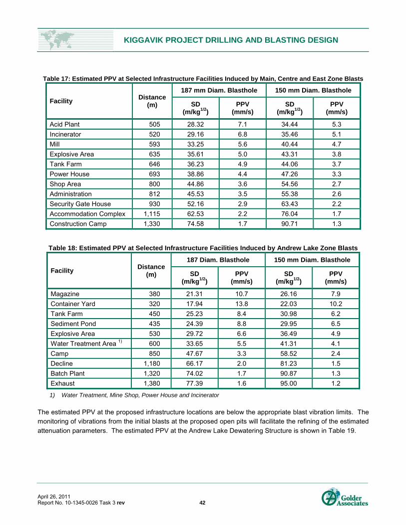
KIGGAVIK PROJECT DRILLING AND BLASTING DESIGN
April 26, 2011 Report No. 10-1345-0026 Task 3 rev 42
Table 17: Estimated PPV at Selected Infrastructure Facilities Induced by Main, Centre and East Zone Blasts
Facility Distance
(m)
187 mm Diam. Blasthole 150 mm Diam. Blasthole
SD (m/kg1/2)
PPV (mm/s)
SD (m/kg1/2)
PPV (mm/s)
Acid Plant 505 28.32 7.1 34.44 5.3
Incinerator 520 29.16 6.8 35.46 5.1
Mill 593 33.25 5.6 40.44 4.7
Explosive Area 635 35.61 5.0 43.31 3.8
Tank Farm 646 36.23 4.9 44.06 3.7
Power House 693 38.86 4.4 47.26 3.3
Shop Area 800 44.86 3.6 54.56 2.7
Administration 812 45.53 3.5 55.38 2.6
Security Gate House 930 52.16 2.9 63.43 2.2
Accommodation Complex 1,115 62.53 2.2 76.04 1.7
Construction Camp 1,330 74.58 1.7 90.71 1.3
Table 18: Estimated PPV at Selected Infrastructure Facilities Induced by Andrew Lake Zone Blasts
Facility Distance
(m)
187 Diam. Blasthole 150 mm Diam. Blasthole
SD (m/kg1/2)
PPV (mm/s)
SD (m/kg1/2)
PPV (mm/s)
Magazine 380 21.31 10.7 26.16 7.9
Container Yard 320 17.94 13.8 22.03 10.2
Tank Farm 450 25.23 8.4 30.98 6.2
Sediment Pond 435 24.39 8.8 29.95 6.5
Explosive Area 530 29.72 6.6 36.49 4.9
Water Treatment Area 1) 600 33.65 5.5 41.31 4.1
Camp 850 47.67 3.3 58.52 2.4
Decline 1,180 66.17 2.0 81.23 1.5
Batch Plant 1,320 74.02 1.7 90.87 1.3
Exhaust 1,380 77.39 1.6 95.00 1.2
1) Water Treatment, Mine Shop, Power House and Incinerator
The estimated PPV at the proposed infrastructure locations are below the appropriate blast vibration limits. The
monitoring of vibrations from the initial blasts at the proposed open pits will facilitate the refining of the estimated
attenuation parameters. The estimated PPV at the Andrew Lake Dewatering Structure is shown in Table 19.

KIGGAVIK PROJECT DRILLING AND BLASTING DESIGN
April 26, 2011 Report No. 10-1345-0026 Task 3 rev 43
Table 19: Estimated PPV at the Andrew Lake Dewatering Structure
Location Blast Location Distance
(m)
Est. Maximum PPV (mm/s)
150 mm Hole 187 mm Hole
Andrew Lake Dike Pit center 490 5.5 7.4
Pit crest 120 43.3 58.5
Estimates shown in Table 19 suggest that blast-induced PPV levels should be below the 50 mm/s limit at the pit
centre while blasts conducted near the pit crests may exceed that limit for blasts using 187 mm diameter holes.
The estimates of PPV amplitude are likely to change resulting from changes to the mine plan, pit optimization,
dike alignment optimization, blast design optimization, and calibration of the vibration attenuation model.
Ongoing blast monitoring will provide guidance as to when, if at all, blast designs should be altered to
accommodate vibration levels at the dike. The smaller diameter holes (150 mm) could also be used for the initial
waste stripping at Andrew Lake.
Ground vibrations induced by the underground operations at the End Grid deposit should not impact the local
infrastructure due to the relatively large distances from the closest structures and small explosive charge loads.
7.4 Flyrock Range Numerous studies of flyrock projection have been conducted and studied. These include Lundborg (1981),
Roth (1981), Workman and Calder (1994), St. George and Gibson (2001), Richard and Moore (2004 and 2005),
Little (2007), and McKenzie (2009). In general, these are based on kinematic equations to describe the motion
of rock fragments after ejection. McKenzie (2009) developed and presented equations to predict maximum
flyrock range and the size of particle achieving the maximum range for blasts of varying rock density, blasthole
diameter, explosive density and the state of confinement. The publication also presented guidelines to establish
personnel clearance distances as a function of charge design and implementation. The maximum flyrock range
is given by:
11 ..
where Rmax is the flyrock range (m)
SDBm is the Scaled Distance of Burial (metric)
is the hole diameter (mm)
Fs is the shape factor (usually between 1.1 to 1.3 describes most flyrock fragments well)
SDBm is given by the following:
0.00050.00923 .
where St is the stemming length (m)
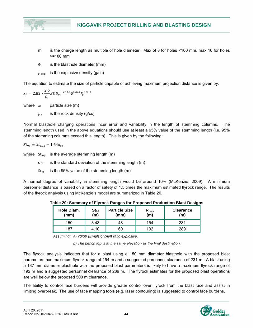
KIGGAVIK PROJECT DRILLING AND BLASTING DESIGN
April 26, 2011 Report No. 10-1345-0026 Task 3 rev 44
m is the charge length as multiple of hole diameter. Max of 8 for holes <100 mm, max 10 for holes
>=100 mm
is the blasthole diameter (mm)
exp is the explosive density (g/cc)
The equation to estimate the size of particle capable of achieving maximum projection distance is given by:
2.822.6 . . .
where xf particle size (m)
r is the rock density (g/cc)
Normal blasthole charging operations incur error and variability in the length of stemming columns. The
stemming length used in the above equations should use at least a 95% value of the stemming length (i.e. 95%
of the stemming columns exceed this length). This is given by the following:
1.64
where Stavg is the average stemming length (m)
σ St is the standard deviation of the stemming length (m)
St95 is the 95% value of the stemming length (m)
A normal degree of variability in stemming length would be around 10% (McKenzie, 2009). A minimum
personnel distance is based on a factor of safety of 1.5 times the maximum estimated flyrock range. The results
of the flyrock analysis using McKenzie’s model are summarized in Table 20.
Table 20: Summary of Flyrock Ranges for Proposed Production Blast Designs
Hole Diam. (mm)
St95 (m)
Particle Size (mm)
Rmax
(m) Clearance
(m)
150 3.43 48 154 231
187 4.10 60 192 289
Assuming: a) 70/30 (Emulsion/AN) ratio explosive.
b) The bench top is at the same elevation as the final destination.
The flyrock analysis indicates that for a blast using a 150 mm diameter blasthole with the proposed blast
parameters has maximum flyrock range of 154 m and a suggested personnel clearance of 231 m. A blast using
a 187 mm diameter blasthole with the proposed blast parameters is likely to have a maximum flyrock range of
192 m and a suggested personnel clearance of 289 m. The flyrock estimates for the proposed blast operations
are well below the proposed 500 m clearance.
The ability to control face burdens will provide greater control over flyrock from the blast face and assist in
limiting overbreak. The use of face mapping tools (e.g. laser contouring) is suggested to control face burdens.

KIGGAVIK PROJECT DRILLING AND BLASTING DESIGN
April 26, 2011 Report No. 10-1345-0026 Task 3 rev 45
With the exception of the initial portal entrance blasts, the underground blasting operations at the End Grid will
not present any flyrock risks. Flyrock from the portal entrance blasts can be limited by the use of blasting mats
or other cover.
7.5 Nitrate Loss Mitigation 7.5.1 Nitrate Loss Mechanisms
Mines are subject to regulations limiting ammonia, nitrate and nitrite levels in mine effluents released into the
environment. The primary source of these nitrogen compounds is typically explosive used in blasting operations,
as AN remains a significant component of most explosives used in the mining industry. The amount of AN
entering a local water drainage system is related to site conditions, explosives used, explosive handling and
blast efficiency.
The key mechanisms by which AN is lost to the water drainage system are as follows:
Spillage during blasthole loading or transportation to the blast site;
Dissolution by standing or flowing water through the blasthole;
Erosion of explosive from high flowing water through the blasthole; and
Leaching of undetonated explosive from the blasted muck, including both ore and waste rock.
Although the majority of explosives used will be from the surface open pits, the End Grid underground mine is
also a likely source of nitrate loss. Losses at underground operations can be significant but are often ignored
because of the relatively small volume of explosives used there. The ability to achieve good blast efficiency and
performance is also related to the mining method used and the blast design employed.
An important factor often related to underground blasting operations is the high use of ANFO. Key issues are as
follows:
Spillage of ANFO often occurs as a result of blowback during the pneumatic loading of blastholes and
moving the hose from hole-to-hole. ANFO has no water resistance and will dissolve readily in water.
The direct release of nitrates into water in wet areas. Loading wet blastholes with ANFO can result in a
significant AN loss through dissolution.
Photos 7.1 through 7.4 show typical blasting environments for both open pit and underground situations that are
likely to result in AN loss to the environment.
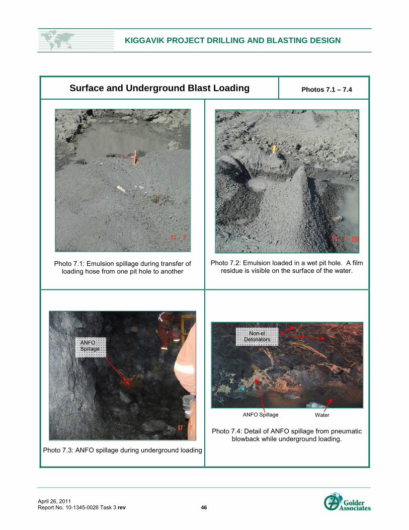
KIGGAVIK PROJECT DRILLING AND BLASTING DESIGN
April 26, 2011 Report No. 10-1345-0026 Task 3 rev 46
Surface and Underground Blast Loading Photos 7.1 – 7.4
Photo 7.1: Emulsion spillage during transfer of loading hose from one pit hole to another
Photo 7.2: Emulsion loaded in a wet pit hole. A film residue is visible on the surface of the water.
Photo 7.3: ANFO spillage during underground loading
Photo 7.4: Detail of ANFO spillage from pneumatic blowback while underground loading.
ANFO Spillage
ANFO Spillage Water
Non-el Detonators
KIGGAVIK PROJECT DRILLING AND BLASTING DESIGN
April 26, 2011 Report No. 10-1345-0026 Task 3 rev 47
7.5.2 Estimated Nitrogen Loss
Following the detonation of AN-based explosive, some residual nitrogen compounds (namely Ammonia, NH3;
Nitrite, NO2; and Nitrate, NO3) are left on the surface of the soils, the rock, the pit walls, etc., and can
subsequently be washed out by surface run-off. Based on field studies at mining operations, Pommen (1983)
and Ferguson and Leask (1988) reported the following factors for expressing the residual nitrogen remaining
after the detonation of AN-based explosives:
Nitrogen loss factor for ANFO: 1% (1% of the mass of nitrogen initially present).
Nitrogen loss factor for the Emulsion: 5-6% (5 to 6% of the mass of nitrogen initially present).
The steps required for the calculation of the nitrogen loss during blasting is as follows:
Compute the quantities of explosives (tonnes per year) to be used;
Compute, from the tonnage of explosives at year “i”, the initial content (tonnes per year) of nitrogen present
in the explosive before use.
Compute, from the tonnage of nitrogen initially present in the explosives at year “i”, the residual load of
Nitrogen (tonnes per year) left on-site after use of the explosive.
Transform the total residual load of nitrogen on-site at year “i” into tonnes per year of each of NO3, NH3 and
NO2 (expressed as N-NO3, N-NH3, N-NO2).
The variables used in the calculation of nitrogen loss during the use of explosives are as follows:
% Emulsion in the explosive – 70% (0% for the End Grid);
% ANFO in the explosive – 30% (100% for the End Grid);
% N in Emulsion – 25%;
% N in ANFO – 33%;
% Residual N from Emulsion left after detonation – 5%;
% Residual N from Emulsion left after detonation – 1%;
% N as N-NO3 – 87%;
% N as N-NH3 – 10%; and
% N as N-NO2 – 3%.
Based on the estimated explosive use during the life of the project, an estimate of the nitrogen loss was
calculated for the three main operating areas: Kiggavik, Andrew Lake and End Grid. This was broken down into
the respective nitrogen contributions from the three primary compounds noted. Figure 17 shows a summary of
the annual nitrogen for the three operations. Table 21, Table 22 and Table 23 tabulate the annual nitrogen loss
from the total explosive use at the Kiggavik, Andrew Lake and End Grid operations, respectively.
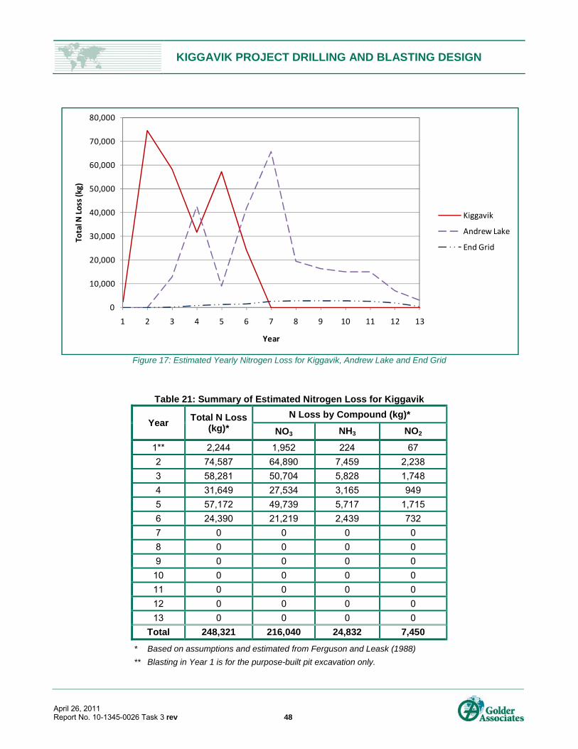
KIGGAVIK PROJECT DRILLING AND BLASTING DESIGN
April 26, 2011 Report No. 10-1345-0026 Task 3 rev 48
Figure 17: Estimated Yearly Nitrogen Loss for Kiggavik, Andrew Lake and End Grid
Table 21: Summary of Estimated Nitrogen Loss for Kiggavik
Year Total N Loss
(kg)*
N Loss by Compound (kg)*
NO3 NH3 NO2
1** 2,244 1,952 224 67
2 74,587 64,890 7,459 2,238
3 58,281 50,704 5,828 1,748
4 31,649 27,534 3,165 949
5 57,172 49,739 5,717 1,715
6 24,390 21,219 2,439 732
7 0 0 0 0
8 0 0 0 0
9 0 0 0 0
10 0 0 0 0
11 0 0 0 0
12 0 0 0 0
13 0 0 0 0
Total 248,321 216,040 24,832 7,450
* Based on assumptions and estimated from Ferguson and Leask (1988)
** Blasting in Year 1 is for the purpose-built pit excavation only.
0
10,000
20,000
30,000
40,000
50,000
60,000
70,000
80,000
1 2 3 4 5 6 7 8 9 10 11 12 13
Total N
Loss (kg)
Year
Kiggavik
Andrew Lake
End Grid
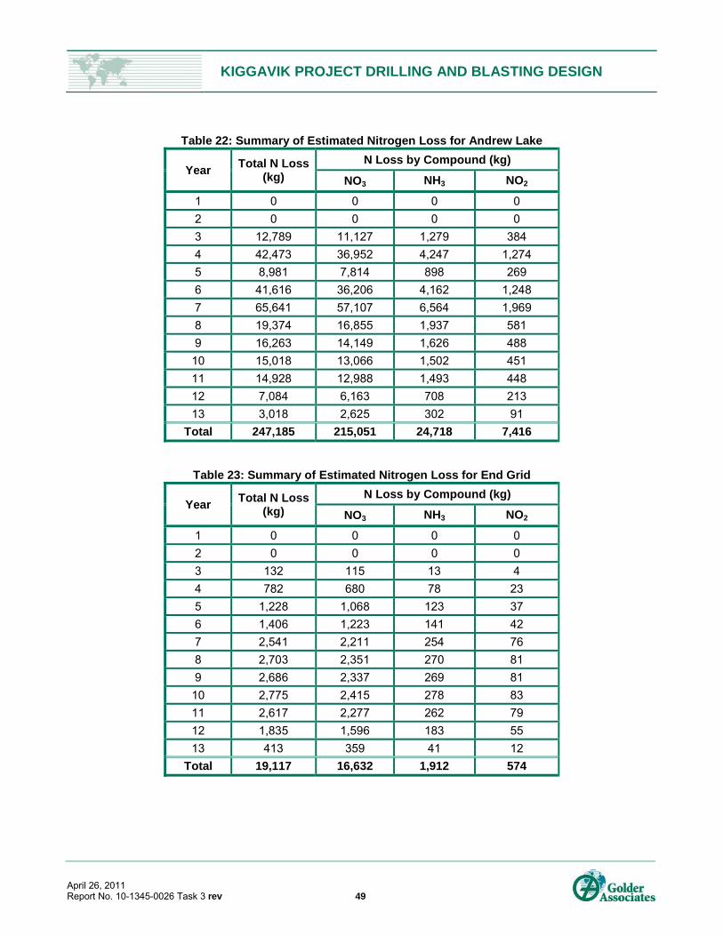
KIGGAVIK PROJECT DRILLING AND BLASTING DESIGN
April 26, 2011 Report No. 10-1345-0026 Task 3 rev 49
Table 22: Summary of Estimated Nitrogen Loss for Andrew Lake
Year Total N Loss
(kg)
N Loss by Compound (kg)
NO3 NH3 NO2
1 0 0 0 0
2 0 0 0 0
3 12,789 11,127 1,279 384
4 42,473 36,952 4,247 1,274
5 8,981 7,814 898 269
6 41,616 36,206 4,162 1,248
7 65,641 57,107 6,564 1,969
8 19,374 16,855 1,937 581
9 16,263 14,149 1,626 488
10 15,018 13,066 1,502 451
11 14,928 12,988 1,493 448
12 7,084 6,163 708 213
13 3,018 2,625 302 91
Total 247,185 215,051 24,718 7,416
Table 23: Summary of Estimated Nitrogen Loss for End Grid
Year Total N Loss
(kg)
N Loss by Compound (kg)
NO3 NH3 NO2
1 0 0 0 0
2 0 0 0 0
3 132 115 13 4
4 782 680 78 23
5 1,228 1,068 123 37
6 1,406 1,223 141 42
7 2,541 2,211 254 76
8 2,703 2,351 270 81
9 2,686 2,337 269 81
10 2,775 2,415 278 83
11 2,617 2,277 262 79
12 1,835 1,596 183 55
13 413 359 41 12
Total 19,117 16,632 1,912 574

KIGGAVIK PROJECT DRILLING AND BLASTING DESIGN
April 26, 2011 Report No. 10-1345-0026 Task 3 rev 50
7.5.3 Mitigation Strategies
In order to minimize any potential impacts an effective explosives management system should be implemented
as part of production start-up. The management strategy should include the following:
An education program for all production employees that outlines the potential problem and appropriate
mitigation techniques;
A spill handling procedure;
A monitoring program that is integrated with baseline water quality information; and
A review of blasting operations early in production to determine efficiency levels.
7.5.4 Observed Ammonia Concentrations
Table 24 summarizes the total ammonia concentrations in mine water from various case studies at surface and
underground mines. This information is from Wiber et al. (1991), Royal Oak Mines (1997), Pommen (1983),
Golder (2006) and Cameron et al. (2007). The table also notes the control measures implemented to reduce the
total nitrogen levels, and, for a few cases, the levels after these actions were taken. It is evident from this data
that in many cases the implementation of more effective blast management procedures, or a change to
explosive type, resulted in significant reductions to measured ammonia concentrations.
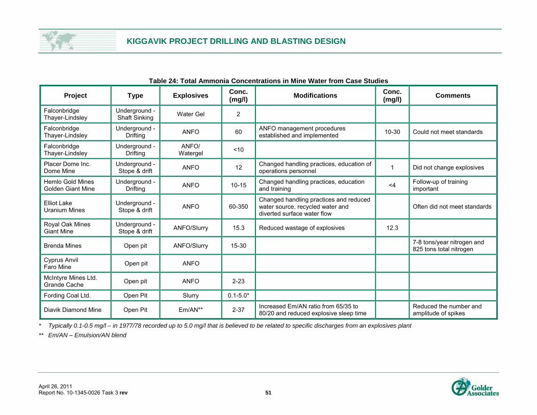
KIGGAVIK PROJECT DRILLING AND BLASTING DESIGN
April 26, 2011 Report No. 10-1345-0026 Task 3 rev 51
Table 24: Total Ammonia Concentrations in Mine Water from Case Studies
Project Type Explosives Conc. (mg/l)
Modifications Conc. (mg/l)
Comments
Falconbridge Thayer-Lindsley
Underground -Shaft Sinking
Water Gel 2
Falconbridge Thayer-Lindsley
Underground -Drifting
ANFO 60 ANFO management procedures established and implemented
10-30 Could not meet standards
Falconbridge Thayer-Lindsley
Underground -Drifting
ANFO/ Watergel
<10
Placer Dome Inc. Dome Mine
Underground - Stope & drift
ANFO 12 Changed handling practices, education of operations personnel
1 Did not change explosives
Hemlo Gold Mines Golden Giant Mine
Underground -Drifting
ANFO 10-15 Changed handling practices, education and training
<4 Follow-up of training important
Elliot Lake Uranium Mines
Underground -Stope & drift
ANFO 60-350 Changed handling practices and reduced water source, recycled water and diverted surface water flow
Often did not meet standards
Royal Oak Mines Giant Mine
Underground -Stope & drift
ANFO/Slurry 15.3 Reduced wastage of explosives 12.3
Brenda Mines Open pit ANFO/Slurry 15-30 7-8 tons/year nitrogen and 825 tons total nitrogen
Cyprus Anvil Faro Mine
Open pit ANFO
McIntyre Mines Ltd. Grande Cache
Open pit ANFO 2-23
Fording Coal Ltd. Open Pit Slurry 0.1-5.0*
Diavik Diamond Mine Open Pit Em/AN** 2-37 Increased Em/AN ratio from 65/35 to 80/20 and reduced explosive sleep time
Reduced the number and amplitude of spikes
* Typically 0.1-0.5 mg/l – in 1977/78 recorded up to 5.0 mg/l that is believed to be related to specific discharges from an explosives plant
** Em/AN – Emulsion/AN blend
KIGGAVIK PROJECT DRILLING AND BLASTING DESIGN
April 26, 2011 Report No. 10-1345-0026 Task 3 rev 52
8.0 CONCLUSIONS AND RECOMMENDATIONS Production and wall control blast designs have been presented for the proposed open pits at the Kiggavik
Project. The blast designs have been based on standard design methods applied to the specific rock types and
structure that is known to exist in the deposit areas. Designs for two open pit blasthole sizes have been
presented, 187 mm and 150 mm. The use of 150 mm diameter holes would result in the need to drill more
blastholes due to the reduction in spacing and burden and, therefore, increase costs.
Where the development of the pit walls is beneath the de-watered lakes (Andrew Lake Zone), wet blasthole
conditions can be expected. Where the walls are developed within permafrost beneath the existing land mass
(Main and Centre Zones), drier blasthole conditions may be encountered, although actual conditions will remain
unknown until the blasting operations commence. In order to limit the water damage to the explosive, which
would result in poor blast performance, a doped emulsion of 70/30 (Emulsion/AN) blend is recommended. A
charge table has been presented for the two blasthole diameters using a 70/30 blend. Although ANFO is a less
expensive explosive product, its lower energy requires a higher drilling density thereby increasing overall drill
and blast costs.
The following is a summary of the findings of our study and recommendations for further work:
Blast layout designs have been presented for the open pit blasting at the Main, Centre and Andrew Lake
Zones. With input from the AREVA and eventual operating experience, other designs may be considered
more appropriate for the mine and should be subjected to analysis using the presented flyrock, vibration
and fragmentation models (or calibrated versions of them).
Proposed blast designs are likely to produce acceptable results for the following:
Fragmentation;
Vibration levels at the existing and proposed infrastructure; and
Flyrock ranges and suggested clearance radii. (These are within the initially proposed clearance zone
of 500 m).
187 mm diameter blastholes may induce PPV amplitudes that exceed the initially proposed limit of 50 mm/s
for the Andrew Lake Dewatering Structure as blasts approach the pit crest. The threshold value of 50 mm/s
may be modified once more detailed information is obtained relating to the foundation materials beneath
the dikes. Ongoing blast monitoring will provide guidance as to when, if at all, blast designs should be
altered to accommodate vibration limits at the dike.
The proposed blast designs are unlikely to induce underwater overpressure levels that are harmful to fish in
the adjacent water bodies. Analyses indicate that blasts are likely to induce PPV levels that are below the
13 mm/s limit (for active spawning beds) at the pit centres, while blasts conducted near the pit crests may
exceed that limit. If spawning activity does occur along these reaches of the above-mentioned water
bodies, maintaining compliance with the DFO guidelines is necessary.
KIGGAVIK PROJECT DRILLING AND BLASTING DESIGN
April 26, 2011 Report No. 10-1345-0026 Task 3 rev 53
Recently updated data on the estimated drill penetration rates, estimated drilling and explosives unit costs
and the cost of accessories were used to provide an order of magnitude estimate of the cost impact
resulting from changes to the explosives, blasthole diameter and blast patterns. The base case design of
187 mm diameter holes using a 70/30 Emulsion/AN blend provides a lowest cost option that can be used
routinely in all conditions, wet or dry, without modifying drilling patterns or blast procedures.
The ground vibration, flyrock, fragmentation, and instantaneous underwater overpressure analyses
presented in this report are based on empirical formulae which are commonly used in the blasting industry
to assess these effects from blasting. The models are intended to provide initial approximations only and
they should be calibrated with actual site data to provide refined estimates. It is suggested that monitoring
programs be developed and conducted to calibrate and refine the ground vibration, flyrock and
fragmentation models presented in this report. These could be initiated in advance of the main blasting at
the Kiggavik open pits, possibly as test blasts when early waste stripping commences.
The use of face mapping tools (e.g. laser contouring) is suggested to ensure that face burdens are
controlled. This will provide greater control over flyrock from the blast face and assist in limiting overbreak.
Contract development mining will be retained for primary development and production ore mining at the
End Grid underground operation. The limited size of the blasts and charge weights, as well as the large
distances from the proposed infrastructure and lakes, will limit the potential impact by vibration and
instantaneous water overpressure. Flyrock will only be a concern for the portal construction. The use of
blasting mats or other cover should mitigate this risk. In order to limit the loss of nitrogen compounds to the
environment, the use of packaged Emulsion explosives could be considered. This will also help to maintain
good blast performance and efficiency.
The annual total nitrogen loss, as well as that for the three primary nitrogen compounds, has been
estimated for the life of mine. The total annual estimated nitrogen loss ranges from 2,244 kg (Year 1) to
74,904 kg (Year 4) and a total life of mine nitrogen loss estimated at approximately 514,600 kg.
In order to mitigate the potential impacts of AN loss from the blasting operations, an effective explosives
management system should be implemented as part of production start-up. This should be done for both
the open pit and underground operations.
KIGGAVIK PROJECT DRILLING AND BLASTING DESIGN
April 26, 2011 Report No. 10-1345-0026 Task 3 rev 54
9.0 REFERENCES AMEC Earth and Environmental, 2004. “Ammonium Nitrate and Explosives Management Plan, Jericho Diamond
Mine, Nunavut”, submitted to Tehera Diamond Corporation, Toronto, Ontario.
AREVA Resources Canada Inc., 2007. “Kiggavik Project Prefeasibility Report – Section 5 Geology and
Resources”. Revision 1. November 2007.
Charlie, W. A., Doehring, D. O., and Lewis, W.A. (1987). “Explosive Induced Damage Potential to Earthfill Dams
and Embankments”, Proceedings of the 13th Annual Conference on Explosives and Blasting Technique,
Society of Explosives Engineers, Feb. 1-6, Miami.
Golder Associates Ltd., 1989. “Report to Urangesellschaft Canada Limited on the Mining Geotechnical Aspects
of the Proposed Kiggavik Uranium Operations”. Volume I of II and Volume II of II. Project #882-1421/881-
1814G. August 1989.
Golder Associates Ltd., 2006. “Review of Blasting Operations And Explosives Management Diavik Diamond Mines Dcn 103”, Mackenzie Valley Land and Water Board website www.mvlwb.ca/WLWB/Registry/DDMI/N7L2-1645/Ammonia-AppendicesComplete.pdf.
Cameron, A., Corkery, D., Forsyth, B., Gong, T. and MacDonald, G., 2007. “An Investigation of Ammonium
Nitrate Loss to Mine Discharge Water at Diavik Diamond Mines”. Proceedings of Explo’ 2007, Blasting:
Techniques and Technology, Australian Institute of Mining and Metallurgy, Australia, 14 pp.
Forsberg, H., and Åkerlund, H. (1999). “Kväve och sprängämnesrester i LKABs malm-gråbers-och
productflöden,Diploma work, Luleå University of Technology.
Furguson, K.D., and Leask, S.M., 1988. “The Export of Nutrients from Surface Coal Mines”, Regional Program
Report 87-12, Environment Canada.
Golder Associates Ltd., 2009. “Geotechnical Recommendations for the Proposed Kiggavik Main, Kiggavik
Centre and Andrew Lake Open Pit”, submitted to AREVA Resources Canada Inc.
Golder Associates Ltd., 2009b. “Draft 2009 Kiggavik Geotechnical and Hydrogeological Investigation Data
Report”. November, 2009. Project #09-1362-0613. November 2009.
Hagan, T.N. and Bulow, B., 2000. “Blast Designs to Protect Pit Walls”, in Slope Stability in Surface Mining, ed.
Hustrulid, W.A., McCarter M.K. and Van Zyl, D.J.A.
Julius Kruttscnitt Mineral Resource Centre (JMRC), 1996. “Open Pit Blast Design: Analysis and Optimization”,
ed. A. Scott, 342 pp.
Little, T.N., 2007. “Flyrock Risk”, in Proceedings of Explo 2007, Wollongong, New South Wales, Australia,
p. 35-43.
Lundborg, N., 1981. “The Probability of Flyrock”, SveDeFo Report Ds 1981:5. 39 pp.
Mattila, K., Zaitsev, G. & Langwaldt, J., 2007. “Biological Removal Of Nutrients From Mine Waters”, Biologinen
ravinteiden poisto kaivosvedestä. Final report - loppuraportti. 99 p. ISBN 978-951-40-2060-5 (PDF), from
http://www.ymparisto.fi/download.asp?contentid=78492&lan=fi
KIGGAVIK PROJECT DRILLING AND BLASTING DESIGN
April 26, 2011 Report No. 10-1345-0026 Task 3 rev 55
McKenzie, C.K. and Holley, K.G., 2004. “A Study of Damage Profiles Behind Blasts”, in General Proceedings of
the 30th Annual Conference on Explosives and Blasting Technique, Society of Explosives Engineers,
pp 203-215.
McKenzie, C.K., 2009. “Flyrock Range & Fragmentation Size Prediction”, in Proceedings of the 35th Conference
on Explosives and Blasting Technique, Vol. 2, ISEE.
Ontario Provincial Standard Specification (OPSS) 120, 2008. “General Specification for the Use of Explosives”,
April, 2008.
Oriard, L.L., 2002. “Explosives Engineering, Construction Vibrations and Geotechnology”, International Society
of Explosive Engineers, 680 pp.
Pommen, L.W., 1983. “The Effect on Water Quality of Explosives Use in Surface Mining”, British Columbia MOE
Technical Report 4, Volume 1.
Richards, A.B. and Moore, A.J., 2004. “Flyrock Control – By Chance or Design”, in Proceedings of the 30th
Conference on Explosives and Blasting Technique, Vol. 1, ISEE, New Orleans.
Richards, A.B. and Moore A.J., November 2005. “Kalgoorlie Consolidated Gold Mines – Golden Pike Cut-Back
Flyrock control and Calibration of a Predictive Model”, Terrock Consulting Engineers.
Richards, A.B. and Moore, A.J., 2007. Effect of Blasting on Infrastructure”, in Proceedings of Explo 2007,
Wollongong, New South Wales, Australia, p. 45-50.
Royal Oak Mines Inc., 1997. “The Giant Mine Water Licence N1L2-0043, Application for the Renewal Giant Mine
Water Use Licence”, Supporting Documentation.
Schettler, L. and Brashear, S., 1996. “Effect of Water on ANFO/Emulsion Blends in Surface Mining”, General
Proceedings of the 22nd Annual Conference on Explosives and Blasting Technique, Society of Explosives
Engineers, pp 117-129.
Scott, A. ed., 1996. “Open Blast Design, Analysis and Optimization”, J.K.M.R.C. University of Queensland,
p. 298-299.
Siskind, D.E. and Stagg, M.S., 1993. “Response of Pressurized Pipelines to Production-Size Mine Blasting”, in
Proc. 9th Annual Symposium on Explosives and Blasting Research, International Society of Explosives
Engineers, pp. 129-148.
Wiber, M., Joyce D.K., Connel R., Luinstra W., Michelutti B., Bell B., 1991. “Environmental Aspects of Explosives
Use”, presented at the Northwest Mining Association Short Course, Spokane, Washington, December 1-3,
1991.
Workman, J.L. and Calder, P.N., 1994. “Flyrock Prediction and Control in Surface Mine Blasting”, in Proceedings
of the 20th Conference on Explosives and Blasting Technique, ISEE, p. 59-73.
Wright, D. G. and Hopky, G. E., 1998. “Guidelines for the Use of Explosives In or Near Canadian Fisheries
Waters”, Canadian Technical Report of Fisheries and Aquatic Sciences 2107: iv + 34 pp, Fisheries and
Oceans Canada.

KIGGAVIK PROJECT DRILLING AND BLASTING DESIGN
April 26, 2011 Report No. 10-1345-0026 Task 3 rev
Report Signature Page
GOLDER ASSOCIATES LTD.
Dan Corkery, B.Sc. David Sprott, P.Eng. Senior Mining Consultant Associate
DJC/DS/lb
n:\active\2010\other offices\1345 calgary\10-1345-0026 areva kiggavik\kiggavik blasting\report\1013450026_task_3_ final rpt 11apr26 kiggavik_mine_blast_design.docx
KIGGAVIK PROJECT DRILLING AND BLASTING DESIGN
April 26, 2011 Report No. 10-1345-0026 Task 3 rev
APPENDIX A Canadian Explosives Regulations

����������� ���������������� ��������
�� ������ ������ �������� ����� ����������� ��������
��� ������������ �������� ���� ������������������������������������������������� �
����� !!"
���
��������������
������ � � � � � � � � � � � � � � � � � � � � � � � � � � � � � � � � � � � � � � � � � � � � � � � � � � � � � � � � � � � � � � � � � �
��������������� � � � � � � � � � � � � � � � � � � � � � � � � � � � � � � � � � � � � � � � � � � � � � � � � � � � � � � � � � � � �
����������������� � � � � � � � � � � � � � � � � � � � � � � � � � � � � � � � � � � � � � � � � � � � � � � � � � � � � � � � � � � �
��� ���������� � � � � � � � � � � � � � � � � � � � � � � � � � � � � � � � � � � � � � � � � � � � � � � � � � � � � � � � �
��� ��!�"����#� ������ � � � � � � � � � � � � � � � � � � � � � � � � � � � � � � � � � � � � � � � � � � � � � � � � �
��$ �������%�������� �&������� � � � � � � � � � � � � � � � � � � � � � � � � � � � � � � � � � � � � � � � � �
��' �%%����%�������� � � � � � � � � � � � � � � � � � � � � � � � � � � � � � � � � � � � � � � � � � � � � � � � � �
��( ������������) ��% ���!�"��� � � � � � � � � � � � � � � � � � � � � � � � � � � � � � � � � � � � � � � � � � $
��* ���������!���&���&�+�� ��� � � � � � � � � � � � � � � � � � � � � � � � � � � � � � � � � � � � � � � � � $
��, ��-����������� ���&��.��/%���� � � � � � � � � � � � � � � � � � � � � � � � � � � � � � � � � � � � � � � $
��0 1� ��#�!-��� 2��!��������&2���&����� ��� � � � � � � � � � � � � � � � � � � � � � � � � � � � � � $
��3 4���� ������!��� ��#�!-����!� � � � � � � � � � � � � � � � � � � � � � � � � � � � � � � � � � � � � � � � � '
���5 4��6�%��)������� ��� ������� %� ����#��� � � � � � � � � � � � � � � � � � � � � � � � � � � � � � � '
���� 7 ����� ��%%��� ���������� � � � � � � � � � � � � � � � � � � � � � � � � � � � � � � � � � � � � � � '
���� 4����������� ��� ������� � � � � � � � � � � � � � � � � � � � � � � � � � � � � � � � � � � � � � � � � � � � '
���$ 4���� ������!��� ���6�������1��� � � � � � � � � � � � � � � � � � � � � � � � � � � � � � � � � � � � � � '
���' ��!� � � � � � � � � � � � � � � � � � � � � � � � � � � � � � � � � � � � � � � � � � � � � � � � � � � � � � � � � � � � � (
���( ������ ������� � � � � � � � � � � � � � � � � � � � � � � � � � � � � � � � � � � � � � � � � � � � � � � � � � � � � (
$������������ � � � � � � � � � � � � � � � � � � � � � � � � � � � � � � � � � � � � � � � � � � � � � � � � � � � � � � � � � � � � � � (
$�� �� ��� ����� � � � � � � � � � � � � � � � � � � � � � � � � � � � � � � � � � � � � � � � � � � � � � � � � � � � � � (
$�� 8�����!� � � � � � � � � � � � � � � � � � � � � � � � � � � � � � � � � � � � � � � � � � � � � � � � � � � � � � � � � � *
$�$ 8�� �9��/��!� � � � � � � � � � � � � � � � � � � � � � � � � � � � � � � � � � � � � � � � � � � � � � � � � � � � � *
$�' �/����!�� � ����4� 9�!� � � � � � � � � � � � � � � � � � � � � � � � � � � � � � � � � � � � � � � � � � � *
$�( �%/�)�� � ����4� 9�!� � � � � � � � � � � � � � � � � � � � � � � � � � � � � � � � � � � � � � � � � � � � � *
$�* ��� 9��!�8��!-�� � � � � � � � � � � � � � � � � � � � � � � � � � � � � � � � � � � � � � � � � � � � � � � � � � � ,
$�, �������������� 9 � � � � � � � � � � � � � � � � � � � � � � � � � � � � � � � � � � � � � � � � � � � � � � � � � ,
$�0 �� ��� ������-��� � � � � � � � � � � � � � � � � � � � � � � � � � � � � � � � � � � � � � � � � � � � � � � � � � � ,
'���#������������4��������� � � � � � � � � � � � � � � � � � � � � � � � � � � � � � � � � � � � � � � � � � � � � � � ,
'�� �� �� ���������6/�� ��� � � � � � � � � � � � � � � � � � � � � � � � � � � � � � � � � � � � � � � � � � � 0
'�� ���:�6/�� ����+�� ���!�� � ���� � � � � � � � � � � � � � � � � � � � � � � � � � � � � � � � � � � � 3
'�$� #� ���#�; ����+):#�; � � � � � � � � � � � � � � � � � � � � � � � � � � � � � � � � � � � � � � � � � � � � � 3
'�' ���������� � � � � � � � � � � � � � � � � � � � � � � � � � � � � � � � � � � � � � � � � � � � � � � � � � � � � � � � 3
'�( �6/�� ��� ����� ���!� ��� � � � � � � � � � � � � � � � � � � � � � � � � � � � � � � � � � � � � � � � � � � � 3
'�* �;��� -�/��&����� ����� � � � � � � � � � � � � � � � � � � � � � � � � � � � � � � � � � � � � � � � � � � � �5
'�, ��/�����!����-��� � � � � � � � � � � � � � � � � � � � � � � � � � � � � � � � � � � � � � � � � � � � � � � � �5
(��������4�����1��<4#���=�� � � � � � � � � � � � � � � � � � � � � � � � � � � � � � � � � � � � � � � � � � � � � � ��
��
*���������������1��<4#���=�� � � � � � � � � � � � � � � � � � � � � � � � � � � � � � � � � � � � � � � � � � � � ��
*�� �)��%������&������!�) ����������%������� � � � � � � � � � � � � � � � � � � � � � � � � � � � ��
*�� �%�� ���2�7����!��2���&��%%����%��������:+� �&��6/�� ��� � � � � � � � � � � � � �$
*�$ �� ��� ������)����������� � � � � � � � � � � � � � � � � � � � � � � � � � � � � � � � � � � � � � � � � � � �'
*�' �� ��� ������)��%�� ���� � � � � � � � � � � � � � � � � � � � � � � � � � � � � � � � � � � � � � � � � � �'
*�( ����&����!��6/�� ��� � � � � � � � � � � � � � � � � � � � � � � � � � � � � � � � � � � � � � � � � � � � � �'
*�* +��)��!��6/�� ��� � � � � � � � � � � � � � � � � � � � � � � � � � � � � � � � � � � � � � � � � � � � � � � � �(
�44����<���:�>������?:����������+#��1�����������+#�������
�<4#���=�� � � � � � � � � � � � � � � � � � � � � � � � � � � � � � � � � � � � � � � � � � � � � � � � � � � � � � � � � � � � � � � � �,
� ��!��-������� � � � � � � � � � � � � � � � � � � � � � � � � � � � � � � � � � � � � � � � � � � � � � � � � � � � � � � � � �,
����� �� �������) ��%����+�� ���!��6/�� ��� � � � � � � � � � � � � � � � � � � � � � � � � � � � � � �,
��)��%�������!�� � � � � � � � � � � � � � � � � � � � � � � � � � � � � � � � � � � � � � � � � � � � � � � � � � � � � � � � �,
����&!�&����������8�"��&����� ��� �������&���( � � � � � � � � � � � � � � � � � � � � � � � � � � � � � � �0
�44����<�+�:����4#��1�����1���=�����?������#��8��� � � � � � � � � � � � � � � � � �3
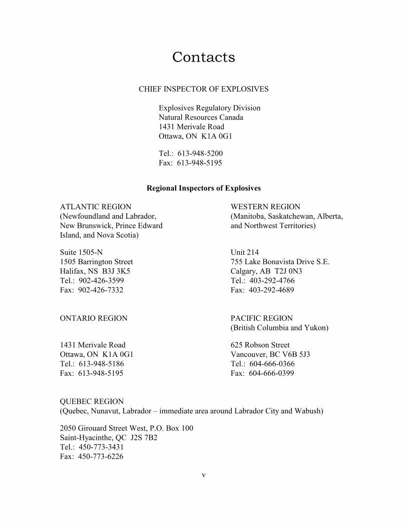
�
��������
8��1����4������1��<4#���=��
�6/�� ��� ���!������)����� ���
���������� ��� � ����&�
�'$��������������&
����;�2�����@���5��
����A��*�$:3'0:(�55
1�6A��*�$:3'0:(�3(
������������ ����������������
��#����������� 7�������������
B��;���&���&���&�#����&��2 B��������2��� 9�� -�;��2��������2
��;�+��� ;� 92�4��� ���&;��& ��&�����-;� ������������ C
� ���&2���&������� ����C
�������(5(:� �������'
�(5(�+�����!���������� ,((�#�9��+����� �������������
8����62�����+$D�$@( ��!��)2��+����D�5�$
����A��35�:'�*:$(33 ����A��'5$:�3�:',**
1�6A��35�:'�*:,$$� 1�6A��'5$:�3�:'*03
�������������� 4��1��������
B+���� -����%������&�?�9��C
�'$��������������& *�(���� ���������
����;�2�����@���5�� =�� �����2�+�=*+�(D$
����A��*�$:3'0:(�0* ����A��*5':***:5$**
1�6A��*�$:3'0:(�3( 1�6A��*5':***:5$33
>��+���������
B>���� 2��������2�#����&���E��%%�&���������������&�#����&�����)���&�7��� -C
�5(5��������&��������7� �2�4����+�6��55
�����:8)� ���-�2�>��D���,+�
����A��'(5:,,$:$'$�
1�6A��'(5:,,$:*��*

��
� ������������� ���� � ��������������
4��� �� �� ��������;��� ������!�����)������������%��������%��������&�&� �%�������� �����-�
�6/�� ��� ���!������)����� ���2� � -�� A
F �-������������� ���&���!������� G
F 1����>������):�� ��� ������� �����!�;��-��� ���������! G
F +������� ���&�&��� ���� ������� ���A
: ������� �� � ������� ���!��6/�� ��� G
: �� ��� ��&�� �!�����)/��*�%�!�"��� ���� ���&:�����2�������!-����&��������&�&
����!�G
F �//�� ������1��%��5�������������%�!�"������ �� �G���&
F ��-����6/�� ��� :������&�����%������
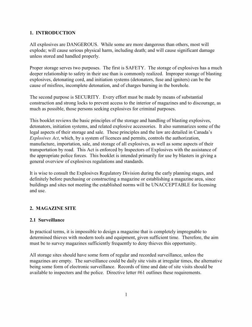
�
������� !���
�����6/�� ��� �����������������7-���� �%������%����&��!���� ��-�����-�� 2�%� ��;���
�6/��&�G�;���� �� �� ����� �/-) � ���-��%2��� ��&��!�&���-G���&�;���� �� �� �!��� ����&�%�!�
���� � ����&���&�-��&��&�/��/���)�
4��/��� ����!�� ���� ��;��/��/� � ����-���� ��� ���1��?����-�� ����!�����6/�� ��� �-� ���%� -
&��/����������� -�/���� ���)�����-����� ���-���� � �%%���)������"�&����%/��/��� ����!������� ���!
�6/�� ��� 2�&��������!� ��&2���&������������ ) ��% �B&�������� 2�� ����&��!����� C� �������-�
�� ����%� ��� 2��� �%/�����&���������2���&��� -��!� �������!�����-������-����
�-�� � ��&�/��/� ��� �������?�������)������%� �����%�&���)�%��� ��� �� �������
�� ��� �������&� ����!��� 9 ����/�������� � �����-�������������%�!�"��� ���&����&� ����!�2��
%� -�� �/� ����2��-� ��/�� �� � ��9��!��6/�� ��� ���� ��%�����/��/� � ��
�-� ����9���������; ��-���� � �/��� �/�� ����-�� ����!����&�-��&���!������ ���!��6/�� ��� 2
&�������� 2������������ ) ��% 2���&�������&��6/�� ����� � ���� �������� �� �%%���"� � �%�����-�
��!���� /� � ����-���� ����!����&� �������-� ��/��� �/�� ���&��-����;�����&������&�������&�H
����������� 2�;-� -2��)��� ) ��%����� �� � ���&�/��%�� 2� ������ ��-�����-���"�����2
%���� ����2��%/��������2� ���2���&� ����!���������6/�� ��� 2�� �;����� � �%��� /� � ����-���
���� /����������)����&����-� �� ��� ����� �&��)��� /� ��� ����6/�� ��� �;��-��-��� � ��� ���
�-���//��/������/��� ���� � ����-� ����9����� ������&�&�/��%����)����� ���)���� ��� ����!����!��
!��������������;����6/�� ��� ���!������� ���&� ���&��& �
���� �;� ����� �� �����-���6/�� ��� ���!������)����� ����&����!��-������)�/������!� ��!� 2���&
&�������)�������/�� -� ��!���� �� ��� ���!���%�!�"�������� ����� -��!���%�!�"��������2� �� �
����&��! ���&� ��� �����%�����!��-��� ����� -�&����% �;�����������4��+#������� �� ��!
��&�� ��
"�#$%$&��'��
"��'(�������� �
���/�� �� ������% 2����� ��%/� ��������&� �!����%�!�"�����-���� � �%/�����)��%/��!��������
&����%���&��-���� �;��-�%�&�������� ���&��.��/%���2�!����� �� �������%�����-������2��-����%
%� �������� ����)�%�!�"��� � �� �����)���.�����)����&��)��-���� ��-� ��//�������)���
���� ����!�� ��� � -���&�-���� �%����%�����!�������&��� ��&�&� ��������� �2����� ��-�
%�!�"��� ������%/�)����-�� ��������� �� ���&����&���)� ������ �� ��������!�������%� 2��-�������������
����!� �%����%������ ����� � ��������� ������ ��& �����%����&�&������ ������ �� � -���&���
��������������� /� ��� ���&��-��/��� �������� ������������I*��������� ��-� ����.����%��� �
'������)*���������)��������������)�����( ������+'���,# �� -"../
�
��)�%�!�"���� �����-��� ��� �������9:����������%/��&�����9:���%� ���� ��� �� ��������� ���
�&&��������)2��� ��%������ �����)�����-��������� ��� � 2�� ���&� ���&��)������)�%�!�"��������9:��
���/��� ������%�����2��-����-�� ��������� ��������%� ������� ��� �&�
"�"# ���0���1� �����
��%�!�"���� -���&���� ������&� ���-����-��� �&�������6/�� �������� � ������ �� �������9��)���
�� ����)� ����� �&�%�!�������-�������&��! ������J��)����/�� �� ����-��%���%�%�&� ��� � ��)
;-� -���%�!�"����%� ����� �/�����&���%���-�������&��! ����/�� � �����&�/��&��������-�
%�6�%�%�.������)����6/�� ��� � ����&�����-��%�!�"���������)�������%����������&�2��-�
>������):�� ��� �������2� �%/���&���%��� ��&)����-���� � ����� ��&�&��6/�� ��� 2�������9��
� ���!��&������//�����!��-�� ���������%�!�"���� ��������!�!������%���� ���&��)/� ����6/�� ��� ��
���� ��%/-� �"�&��-����-� ������%���%�%�&� ��� � �����������&� ��� � � -���&������ ����&
;-�������/� �������&�!�������&� ��� � ���� /� �� � � � �%�)����%��&����)�����������
�//��&�6�������� �%%��)����-��>������):�� ��� ��������
7-������� ��%/�� �� ��������� ���%� ������ ����������-���6/�� ��� ��������%�!�"���� ���&���
� ��&�� ��;��-��-��>������):�� ��� �������������� ���!��6/�� ��� 2�J�&� ��� � ��� ����2� ����!2
��&������ �&��!���%�!�"��� �%�!-��/����&���-�� ���������)�� ����� -��!���%�!�"����������-��
%�)���� -���&��)�&������� �� ��� ����� �%/���� ���&�%�)�� �%%�&������%� -����!���;��!-�
���6/�� ��� ��������%������%�!�"��� �
�-��/��/� ����������� �&��� ����/���� ���-��%�!�"�����&J� ������������%�&��� ��%� �������� 9
�%������!���%�����-���%�!�"��������������)��6/�� ������8�;����2������ �����-����-���6/�� ���
;�������������������&��)� )%/��-��� �&��������������� -���%�����6/�� ���2�%�!�"��� �%� ����
�/�����&��)������� ���-��&� ��� ��!���������-��>������):�� ��� ���������������� �&�&�%�!�"���
B��C�
"�2�������������!����+��������
����)�%�!�"����� � ������&�;��-���$5�%���� �B%C�������&)���;����2�����������%������� � %���
���-�� ����� ���.����&����-������2� ���� ������� /� �������6/�� ��� �������-���&����� �
"�3$�����(��������
7-��� ����&�;��-�����&J� ���������-����6/�� ��� 2�-����-��;��!-�����%%����%���������%� ����
������&�� �����6/�� ������&������ ��&�&�����-���� �� ����%�� �����-��%�!�"������1����6�%/��2���
�(5�9���!��% �B9!C����%%����%���������� � ����&�����!�;��-��(�9!���&)��%���2��-�������
.������)����(5�9!�%� ����� �� �&���&�� ���� ���!��6/�� ��� �����-��� � %������.������):
&� ��� � �
'������)*���������)��������������)�����( ������+'���,# �� -"../
$
��� -���&��������&��-����-��%�6��!����%%����%�����������&���������B��1�C������%���
�6/�� ����� ���!������)����-��� ���-� �������&�� ���)��� �� �����%���� �����!� ����� �����
���� �����������������//�� ��������% �
"�4���������'5�����# ���0���
7-�������������� ) ��% �����9�/�������%�!�"���2������-������ ���!��6/�� ���� -�������9�/������-��
%�!�"�������-�����%�K����������� ) ��% L��� ��&� ��-��&��������)/� ������ ��� 2����:��� ��� 2���&
��� ����� �&�������� 2�;��-����;��-�����-��� �2� -� 9���������&��������!� ��&����� -�&2�� �;�����
&��������!�����) ���&���� ��� � .��� ����� �� ������ �
��� ���-������������� ) ��%�� ��-�����!!������&�&��������� ���-������!)������ ���!��6/�� ��� ���&��
�-��9�)�����-����� ����� ��%�����/��/� � 2�����)������%� �����%�&�����/�����������;���� � ���
��
���� ��� ��&����� ��� � �������� ����!��-������������� ) ��%�%�!�"���� �� ������-����� ���!
�6/�� ��� �%�!�"���2���� -���&���������� ��(5�%���%�������-� �&� ��� ��%�)������&� �&�����-�
&� �������������� /� �������-��.������)���&�������� � ����&�� � %�������)/��3�%�!�"���
B�;�: �%/���%����%�!�"��� C�%�)�������-���"�&��)������ /� ����
"�6����������!��+��+7�������
��� ��&��������!� ��&���&���� ��� � �������4���2����2���� �%�����-�!-��6/�� ��� 2��-���
�6/�� ����/���������%� ����;�) �������������%��&����-�)�%� ����;�) ���� ����&��������� ���!
�6/�� ��� �%�!�"����B������;��-�&�������� C���&�9�/����� �� �&� � � ��������& ���&��������!
��& � -���&���� ����&�;��-�%� 9��!������-��� ����������/�����/��������� ����6/�� ��� �
"�8��-��# ����������+�9(������
���)�%������� ���&��.��/%���2� � -�� �/������%���� 2��-���&�������� ��� ���-���� 9���������
�6/�� ������&��-����������&�&����-��&���!��6/�� ��� �����-��%�!�"�����������-���/�����������-�
%�!�"����%�)��������!-��������-��%�!�"����
"�/:(��1��-����)������!��+)��+!���� ����
1� ����!-��� 2��!������ ��&2���&��!������ ��&� ���� ��� ������6/�� ��� 2�����/�� ����%�����������
-�"��&��-�������6/�� ������ 9���1����-� ���� ��2��-� �����% �%� ��������� ����&�������-�������� ���!
�6/�� ��� ������������������ ) ��%�%�!�"�������2����-��2������ �/�����2�&�)2� � ������ ������
'������)*���������)��������������)�����( ������+'���,# �� -"../
'
"�;*���� ����$������1��-�����
#� ����!���%�!�"��������-���� ������-�!-����9�;������&� ���-��/� ������)����������!� ��� 9��)
��!-����!��������&��!��-��%�!�"����� ��&�� ������������ � ��J� ����� ��������� ��� ��� ���% ��
�/����-���//��� -����-��&�� ���% 2��-��%�!�"����%� ����� �� �&���&�����/�� ������%� ����
��� ����&���%��-���%%�&����������
"��.*�������5����� ��� ��������������1����
��������-��&� ���� � -���&� ��/������� ���(�%���%��-��%�!�"���������&������&��������/��������
��!-����!� ���9����&��-���/�� ��&���&��!����&�����-���6����������-��%�!�"����
1���/�;������� ��6 ��&��!��(�9������� �B9=C�����-��� ����������������!��&����������-��;� �������2
�� �����-������ � ����� ������������������������
1����-���� ��������������)���� ��� ����.��/%��������-����� �&������� �&������%�!�"���2��� ��&��!
�%%��� ������&��� � ��������%� ) ��% 2� �� �����-��� ����� ��������������� ����
������������������ /� ����
"���� �������!���(�� ��������� ��
7 ����� � �%%��� ������&��� � � � -�� � ��������/-��� 2�%��������&�� 2�/�!�� 2��4������ 2��� �2
%� �������������!-���� �&��������������!� ) ��%�%�!�"��������!��&�/�� �� ��� ���������� � -����%
��� �&������%�!�"��� �
"��"*���������� ��� ������ ��
����/����������� ��� ���&��� � �� �&����%�!�"��� 2��� ��&��!����� �&�����&�� 2� �� ������ ���&
��!-���!2�%� �����;������!-�2�&� ����!-�2���&��%/� ���� � �����
"��2*���� ����$��������������:����
1����� ���-�"��&��-���%� ����;�) �������������%��&�;-��� �� �&����!��6/�� ��� � ����!������
!���&��!��� ����2��-��!����& � ������&��!���%�!�"����%� �����%��������&�������%��� -2�;��& 2
&�)�!�� 2���&���-��� �%�� ������%�������������&� ��� ���������� ��0�%�����%�!�"�����������
�� �������� 9 ���� ��&�������:�� � �����%�����������& ��&&�&�����/���� �����
����%��������� �&������� ����%�!�"����������!����&�������B���� ����������� 9�����&��!2���
�6�%/��C�%� ����������: �%�� ������%������� �
'������)*���������)��������������)�����( ������+'���,# �� -"../
(
"��3'����
��������� �!� �%� �����/� ��&���������6/�� ��� � ����!�� ��� � ���-����-��/���� �� �;����&����-�
-�"��&����&����)2��-�� �!� � -���&��������/� ��&������%�������-���;���&������ ����&��������������
��&����� ����)���%��� ����������� ��������&��-������;��!�� � �!!� ��&�� ���!��&�����A
����������� ��������
��;�����!� �!���-���� ����&����������&� ��� ����0�%�%� �����/� ��&������ -�� ���
�//��� -�����-��%�!�"�������-�� �!��%� �����/� ������&� ���-������&�� ���������� �
��;����&�������������&�%���%�"� ��-��/� ������)��-������������ -�������-��&��� ��������-�
�!��;���&�-����-��%�!�"����
�-������;��!�;��& ����;��& �����-�� �%���� ��%� ���//��������-��;�����!� �!�A
�<*1�'=�'
$(�-���0�+*�����������5
��'��>���
=�������������� -����+(�+���-������������
��������� ��������
4��������%�!�"��� ��� ���&������!!��!� ��� 2� �� ��� ����� ��� 2����;��-��� ��)���%�� �%�)
��.�����;�����!� �!� �����/��&��!�����-�������;-�����-��/��������%�!�"��� ������� ���&2
�!��!����.����%��� �%�)�&�/��&������ �����&�/����� ���M��������������!������� ������� �
)������!�������� /� ��� ����&����� ���&�!��&�� ���
"��4������ �%���
�-�������� �������)� ���� �����!������!��.������)����6/�� ��� � -���&����/���� ��&��)��� ���&)2
�� 9��������������-���;������ �����)�/���������-� ������ � ������%� ����� �� �&����������%� ���&
�� 9�&�;-��������-�� ����� ��������&�&�
2�#$%$&��'
2��!�����( ����
��!�"��� ������� ���!��6/�� ��� ���&������������ ) ��% �%� �������������� ����%�����-��� ����
� ��������������� ����������������� !!"2�����-��%� ���� ������� ����
'������)*���������)��������������)�����( ������+'���,# �� -"../
*
#� $������ ��� � %&���������������� ���'���� ������������ ����� ������� ����
��������������� %�����������(������������ %����������� ���'���� ����
����(���)���� �����������(� %�*� +����+(�,
2�"?������
8�����!���%�!�"��� �%�)����/��%����&��������� �����-���� ������������-�����!� ) ��% � ����)
���&�����-��� ����� ��������������� ��������������
2�2?�(��>������
��!���������;:�/��)�%�!�"�����/������ �%� �����%�&������� �����-������;��!A
F �� ����� �����-��N����%�9��!�:������� -� N�����G
F ��!�"������ ����&��6 �� ����)�����-�� ����!�����6/�� ��� G
F ��!�"����9�/�� ��/���� �)� �������&���&���)G
F 8��������� ��������% 2�%�� 2���&�&� ��/�� G
F 4��/��� �� 9��!����6/�� ��� �����;��-�� �� 9��!�����G���&
F 4� 9�!��!����6/�� ��� �/��/���)��&������&�;��-��� ��;��� -�/��&����� ������
���� ��%/����������9��/���%�!�"���� ������� �� ��!���2� ��&2�������� ����%������� � ���%�9�
�6/�� ��� �%���� �� ������
�-�����������%���)�%��)��������� ������������!� ) ��% � ����&������%�!�"���2���!�2���� ��� ���&
���:��� ��� �&�������� 2��������)���&�������/����& 2�������&����������!�- �� �;������1����-�
��� ��2��� ) ��%��� -���� ����;-� -��� -�������)� ������ ����&�����-�������!����� �������� ���&
������&��)� ������&� ��� ��&�� ��� �%%��&�&�
2�3�������!������*� >����
� � ����6/�� ��� � -���&���������/���&������%�!�"�������-�� � ��%� �����/��/���)� �� �&
��������������!��������-��%�!�"��������&������ �� �% ��� �� -���&��-��������/��� � � ������� �
�����&!� ������%�!�"������7-�������/� ����2��� �����&!��%� �������/�� �&������ ����!����� � ���
2�4����5!������*� >����
�%/�)� � � ������-��� �%�� ������%��������%� �������������;�&����� �%�������� �&�������
/��6�%��)������%�!�"�����������%/�)��6/�� ��� �/� 9�!� ���&�/� 9��!�%��������%� ����� ������)
���� ��&���&�&� ���)�&��� �� ���-�)� �� ���������/����������6/�� ������&�����-�"��&��
'������)*���������)��������������)�����( ������+'���,# �� -"../
,
��)�/� 9�!��!���� ����������-���� � �������&����!��&� ��&������;-������� ��%/���&2���&��-���&�&
���� ������������!�) �����������)���-�����.��&��6/�� ���2�%�)������:� �&�����-�� �%��/��/� ���
����%��9��! �%� �����9�/��� ����������� � �������
2�6'�� >���?���-�
����-��������������-��;�������-��%�!�"���2���K �� 9��!�����L�%� �����/�����&������-��;� �
/��%������)�%��9�&�;��-�����&�������5�%����%���� �B%%C�;�&�������&� ��� �������� ���(
����%���� �B %C�����;��-��-��!-�����-��������:�� � �����%�����������-� �� ����/���������������� -��
��%�����������&�/�������%��%/� ���!��-���6/�� ��� �����
� � � -���&����������/���&�����-�!-���&�����������������-�� �� 9��!����������/�� ��� ���&��!���
�-������� -���&������������-��&����-����/� � ��;��-����&�� ���)���
2�8�(��������'�� >
����������%� ����;�) ����/��&�����-������������� �� 9����-����&��� �� 9�%� ������ �&��� �� �� �
%� ���6/�� ��� �&�����������;��-���%��������%� �������9������������������&� �� 9�����-���� 9��
�-��%�!�"����;-�������;� �//�)�� �����!-�����
�-��/�� �� ���� ���� ��������-��%����� -��� ���&�������� ���&� ��� ��-���&�������������%�)���
�&��� �&���&��-��&�������� � -���&����&� ���)�&�;��-� ��������%�!�&�&�������� � -���&�������
� �&�
���%��)��� ��� � �;-���&����������&��6/�� ��� �-������������&����%�!�"��� 2��-�� �� ��-�
�������� �&�����-������������-���6/�� ��� �����-��%�!�"����������-�)�-�&��������%/������)�-��&
��&��������������� ��&����� ����-� ��� ���//��� �����-����������)� � ��%�� ����������
�6/�� ��� ����-������2���)�/�� ������ -��!������%�!�"����%� �� ������)� ������"�������������&
�6/�� ��� �
2�/����( ����'-���
�� ��� ����� -��� ������� ���!��6/�� ��� ���&������������ ) ��% �%�!�"��� �����������������
��.�� �����-���//��/������ -��� �%� �����/� ��&��� �&���� -�%�!�"�������-� �� -��� � -���&���
�����;�&���.�����)��)��-��%�!�"����9��/���
3�1!��'�%$��*�''�''��
�����6/�� ��� �%�!�"��� 2���-����-��������%������)�� ����� -%������&��-� ����&���/����� ���
����������%�������.����)� ��� 2� �%����&����-��J��� &� ����������&�H ������������ �
'������)*���������)��������������)�����( ������+'���,# �� -"../
0
8�;����2���%�!�"���������%�������.����)� ����%�9��!� ��� ����� ��!��-���6/�� ��� ����-�� ���
�� �� �%� ���&����&�����J��� &� ���������-� ��� ������� �����&����-������������� 2� ����!�����
������;�� ���!���� A
�����������������������������
�-�� ����!����&�/� � ��������)�.�������� ������ ���!��6/�� ��� ���&�&�������� �%� �
��� �����&��)���%�!�"������ �� ��B1��%��5�:���!�"����#� �� ���//�� �����C����-���� �� �
� ��-��/��%������/� � ��-��.������)����6/�� ��� ��� ��&�����-���� �� �����-���� �� �
����; � ����!�2������� ��/� � ���2���������-����� ����%�!�"���2�����6�%/��2����&���)
&�������� ���&�/� 9�/ �
���������������
�-�� ����!������)�.������)������ ���!��6/�� ��� ����&�������� ���� ���2�� �;����� ���)
.������)���� �� �!�%���2�%� ����� �����&��)������&��O ��� �� ��B1��%��5�:���!�"���
#� �� ���//�� �����C������� ������� ����&����-������������� ������)�/�� ������ ���2�!���
�;�)2������-��;� ��&� ����������� ���!��6/�� ��� ����&�������� ����� ��� �� �&����&�� ���
�-���� �� ��� ��� ���-��/��%������/� � ��-��.������)����6/�� ��� ��� ��&�����-���� �� ��
�-����������������� �� � �� � ����)���!����������� ��� �������� �� ��� � ��&���������/����-�
� ����)���&� ���)����&�&�����-��/���� ��)��-��%�!�"��� ���&�����-���� ����������/9��/���&
���������/��������)����&� ����!����� ����� -�%�!�"��� ���&��������������� �� �� -���&��//�)���
�-���6/�� ��� ���!������)����� ������&� ����!��-���)/����%�!�"��� �/��/� �&2��-������ �����2
��&��-��%�6�%�%�.������)������� ����&������ -�����
7-���� ��&2����� �� ��%� ������������&�����-�� ����;��-��-��%�!�"��� �������-����� /� ������)
����� /� �������/��� ���� ������-���� �� ��%�)����9�/������-��%����%�!�"��������������� ������
���
3��!������� �����������������
�����6/�� ��� �-�������� �!��&������&������� �B��C���%����������&�!�� 2����;�:&�!��
���� /���������!���� ����& � �� ���%���2���&��� �%/��������)�!���/��������������� ���!
�6/�� ����%�)����&� �!����&��)����5$$�2��� ���(�����-�� �%/��������)�!���/���&� ��� �;-� -
�6/�� ��� � ���������� /����&���&� ����&���!��-�����������-������� �/��-�����&���� ������6/�� ��� ��
�%/��������)�!���/ �+�B%� ��)�&�������� C���&���B%� ��)���� ���!��6/�� ��� C���!��-����
'������)*���������)��������������)�����( ������+'���,# �� -"../
3
3�"���,���������7�������$ ��������
���:�6/�� ������� ���!�� � ���� � � -�� � ���� ���!�;���2���� ���!�%� -��� �����6/��&�� 2
�� ������ ��� 2���&� �/� ��%/�� �%� ��������� ����&������%�!�"���� ��������!��6/�� ��� �
3�21� ��1�����75,1���
4�������� �����!��6/�� ��� 2����� ��� �%%��&�&��-����� ������-������ ���� �� ����&�� ��-�
����������� �&�� ���������������)�/�� ������-������!��������� �%/�)�;��-��-����.����%��� ��
��)�/����� ���M���������������%��� �/�����;���!��&��!��6/�� ��� �
3�3����������
�� ��������������)�%� �����9�/���������� ��/� ������ ���!��6/�� ��� ���&������������ ) ��% �����
%�!�"������&�������)�� �����%����������%� �������9�������� �����-��� �� 9 �&�������6 ��&��-�
�� �� ����%�� �����-��%�!�"����� ��-����;�/����&� ������/�����)�;-�����%�� ������6 ��&�&����
�%/�������������)� ������� -��� �� � -�;������//��&�6�+���������������)� -����/���/��&� ���
�� �%%��&�&�
��%�!�"����9��/���;-��� �� ��6/�� ��� ���� -������� 2���� ��� 2����/�;&��%��M;�%���%� �
9��/����� ��&����-���%���������� ���!��6/�� ��� ���&�&�������� �� ��&���N������ N�%� ���� ����
������)��� ��&�&�������)�/�� �������%� �������9�������� �����-�������6/�� ��� �-��������
N%� ���&N������ ��� ��-�)�%�)�����-�� �� ���� �� �.������ �&��� ����� �!�������%� ������������&
�������)�� ����������������6/�� ��� �
���� ��&�%� �����9�/��������)��6/�� �����-���� �/����������&���9��������� ����!�����-���� ��&
%� ������������&���������� ���-����)��� �������-��&�����-���6/�� ����� ���9��������� ����!��
���� �� 9�%� ����� �����&������� ��%���-�)����� ��� ����-�� �� 9� ���� �%� ������� ��&�&�����-�
��������)����9������� ����&�&� ��/�� �� �%� �������/����&����/��� ����&��-���6/�� ���
��!������)����� ����
�� ��& �%� �����9�/������� � ������ ���������/�� ��&���� ����� ��& �����-�������������-���
3�4����������'������������
����&&����������� �� 9���������)2����&�� ����6/�� ��� �������.����&����%������������ ��&������
��� ����� ��& ������� ��� �%� ������������&���������� ���-����)��� �������-��&�����-���6/�� ���
-��������� ��&�
'������)*���������)��������������)�����( ������+'���,# �� -"../
�5
����-� ��&�) �;-�����6/�� ��� ������-��%��� ��� -�� ����� ���)������-���� 2����� ��%/��������-��
���&�� �&������&���������� �����6/�� ��� ������)�����-�)�&������9��;2�;-�� �������&����)
�-�% ���� 2����;-��&�� �����-����������&�%�!�"������ �� ����
3�6������-��+������ �����
���� � ��/��� ���� � �����-���//��-�� ������&� ���� ������� ��%���� 2����� ��%/���������-�������)
������/� 9�!����� � ������� ���!��6/�� ��� ����&�������� ����/��/���)���&�/��%������)�%��9�&
�����&� �����;��� -�/������ -���&���������"�&��-������ ��%�����/�� ��&��! �����-��2�/���������� �
�;��� -�/�%� ������ ����� -�&���)��&������ �������&������������� ���� ����� �������������&�
�-����!����� /�� ������)��� � �;��-��-�����&������-���6/�� ��� ����%��9��-�� � ������-����6�
�.��������)������������� ���!�������-���&����� ��������&&���/�������� -�/%����;��-��������-�
����;��!A
F � ��H �%�!�"������ �� ����%���G���
F =��&��O �%�!�"������ �� ����%����;-��� ����� ��������-������&��G���
F 4����� �������������������%�!�"������ �� �M/��%�����%����
���� -�/%��������� ���!��6/�� ��� ����&�������� ������� ������ �&� ���������;��-������)�%��9��!
���;��-�����%/��/������2��-��/�� ����� �����!����� ���.�� ��&����-��������� ��&������)�������%��9���
���� ��)���&�&����&��� ��)�;��-��-�� -�//��������)��� �������� ������6/�� ���� ����&�
7-������� � � ���&�������� 2�&��������!� ��& 2���&���� ��� �����/�� -� �&2��-�� -�//����
��.����&����%��9����)��-�������� � �������� ��-���� /�� ������)����-��/�� ����/����!� � -��� � ����
%��9��-�������� ����� ���� /��� ��%%�&�����)�;��-��-���//��/������%�!�"������ �� ����%����
3�8������������-���
����)��� ��� �����-������6/�� ��� 2�;-��-���� ����2� � /� ��&��������%/��&2�%� �������/����&��
.�� 9�)�� �/� �����������-��-���� ���/��� ����&�����-���6/�� ��� ���!������)����� ���G��-��������
��/����%� ��������;�����!�B1��%�$'�:��/�� ��� ��� �&������/���C����-������%������ -���&
�� ��&�A
F 4�� �2�&������&���%�G
F ��!�"��������%�����2� � -�� ��)/����&���!���%���G
F ������2�.������)���&��;��� -�/��&����� ��������%��������6/�� ��� � �����G
F ���-�&�������)���&�/��/���)�&�%�!�G���&
F ��-���/���������&����� �
'������)*���������)��������������)�����( ������+'���,# �� -"../
��
4���$�'*����:�<*1�'=�'
�-��&�):��:&�)����� /������������6/�� ��� ��)�&����� 2� �%%��� ������ 2� �� ��� ����� ��; 2���&
��&���&��� ����/�������%���� �� �� �/��%����)���&����-��J��� &� ��������-��-������� � �����
��������.������ ������� /�����)�����2�%�����2���&���� ����� ��� �� ��J� ������-��-������� ��
��������.������ ���&���-�����!������)�� � ������&�H ������������ ��� �� �� � �%�
��!������� ��-��������������-������ /�������6/�� ��� ���
����)���-� ���� �&�������� /�����6/�� ��� �%� �������� ���&�%� -��� ��� ��&��������&� �/������
���)����� /�����!��6/�� ��� ����-������;��!���.����%��� � -���&����%��A
F �.��//�&�;��-��;�������6���!�� -�� ����&��)��������������� �G
F ��� ��� �;����!�� ��� �����&���&���%�)� � ���&G
F 1�������9 ���&��������� �-����������9 G
F -� � ���&���!������&)����� �������&��������6 � �������&�!��� �G
F +��9� ���&� ������!��������!��&� ��&�����G
F ���� ���������;��������� ���)�&�� ����G���&
F �6/�� ��� �=�-� �������� ������%�����-����555�9!��������� /����&�
�-��/�������������-� ��� ��������!��6/�� ��� �%� �����9�/��������!���2� �%�� ������������� ���
%�������2�%�� -� 2���)� /��9:/��&� ��!������%�:/��&� ��!�&��� �2���&���)� �� ��� ���-��� ���&
�!����� /�������� �)�
��������� �%� �����9�/�� �/��������%���-����6/�� ��� ��������-� ��� ���-����-���6/�� ���������
���%����&�������� �;���������!�������)����-����-����6/�� ��� ����-��&�������� �%� ���������
�%/�����)��� �� �&� ������������ �%/���%�����-���/���� � ��-�%���%�&��������������-�� � ���
������������� ������-�������-����%� ��������� � �����-��&�������� ���%��� �&���-�� ��!�
�%/���%�������-����-� ���
��&������������-� ���%� �������%���%�%����0�)��� ���&2���&����)��� ���&���%�����-����555�9!
� ����� /����&����;��&����� �%� ��� �%/��)�����-� ������6/�� ��� ��������������� /����&�����
/����&���%�����-����5� �� � ������-��� �������-� ��� -���&�����.��//�&�;��-������ 9��!���&
�%%��� ������ ) ��%��������;��-�� �%/��)������ ��������)���-� ��������)���%��
1��������!������ /���������!���� ����& �/�� ��& �����������&� /��)�&������ -� �&��������-� ��
;-������� ������ ��6/�� ��� ��������6/�� ��� ����-�� �%�� �%/��������)�!���/�%�)�������� /����&
��!��-���;��-���� �/����������!��&�� ����-��-�"��&�&��� �������� �����-������ /����������
���!���� ����& ����� ���������� /� �� ����� ����/�� ��&��!�%�6�&����& ����6/�� ��� ��
&�������-�"��&�&��� ��� 2� �%/��������)�!���/ 2���&���-�� ���
'������)*���������)��������������)�����( ������+'���,# �� -"../
��
6���'�� !����:�<*1�'=�'
���� � �%���%� ��� � ��)����&� ���)��6/�� ��� ����-� ���6/�� ��� �%�)������ -�%����������%
�������� ��-���-������������9���&����!����� /��������2�� �����%�����������;-� -��-����� ���
���-���� �������J��2����%�)� �� � ����%���������-���-� �&����������&������ �%����������� �
�-���!-�&�%�!���������������&��6/�� ��� � ������%� -�%����-�"��&�� ��-����-� �����!��&
��&�����2���&�-�� ����.����� /� ���� �������-��&���!���&�&� /� ���
���� ���;�) �/������������ ���� ���-��%���� ������������&������6/�� ��� �/��������&� ���)��!
�6/�� ��� �������� ����� �����������������/� ���������&����%�����-���//��/������&� ��� ����
%��-�& ���
��%��� ����-��/���� �;-��&� ���������&���&��6/�� ��� � -���&���������%/�����&� /� ���
�-�%2����� -���&� ���� ���-������ ���/��� ���� � �
�-�� ���%��-�& ��� �%%��&�&�����-��.������������������������� �����������������
�����&�&�����-��� �����6/����� �&���&� �%/������/��/��2� � -�� ��� -�� ��� ������� ��� ����
���!��.�������� ������ ���!��6/�� ��� �%� �����&� ���)�&2���&����6/����� �&���� �%/������/��/��
���������������������/����%��-��;��92�������-����� ���)�.�� ������������-�� ���)����-�
��&����9��!2��-��-��&���!���&�&� ��� ��������-���6/�� ��� � -���&����&�����&����� ����;��-��
��/�� ������������-��%���� ���������-���6/�� ��������-���6/�� ��� ���!������)����� ������
�&�� ��
� ��/����&����������&��6/�� ��� �%� �����/� 9�!�&�� ��&��!�����-������ /��������������!����
���& ���!������� �������� /��������������&� ��� ����� ����
��� ���-��&� ��� ��������6/�� ��� �%�)� �������������/��������2�/���� �����)�;-����%%����%:
���������� �&���&�;����!����6/�� ��� ������������&2����� ��&�� �������� �� �����-���� ����!�� )
�� /�� ���������-���������%����������/�� ��&��!�
6���5��������+�������5 �����!������������
�����!�) ������B��C:�� �&���� ���!��6/�� ��� 2� � -�� ��-��&)��%��� 2���������������K ;����L���-�
;�����!�%�)�����-���6�&�������������!�) ��������&2����-��!-����� �!�����)��� ��� �&��)� ����!����
��-��2�%�� ����%� /-���2���� ���� ����������&���!��&� ����!�� ��&����� ����;�����!��� ��� �
�-���� �� ������)������ �����
+��& ��������!�) ��������%�����-����� �&����&���& ��� �����&!� 2���&����������%���-���6�&�&
�����!�) ������;���� ��9�������-�������%���&���;��� �&� ����-�� � � 2� ������!��-�%����� ����)�
�-�� ;�����!�%�)������ ����&������������ �����&!� �����/��� � � ���������-��������2��-�� �����&!�
�������/� 9�!� � -���&�����6�%���&���&2��� ����� ���� �����2���9����������)�� �����-�)� -���&���
'������)*���������)��������������)�����( ������+'���,# �� -"../
�$
� ��&����)����-��/�� ����� �����!��-�%���&�� ���& ��-���� ��&�����������-�� ;�����!��� ����&��
��!������-����-�� �����&!� ������� ���� �����2��-�)� -���&����&� ���)�&��)�������!�
�-�����-���"������������� /� �������6/�� ��� �%� ������������&�/���������-������ /����������
&�!��&�&�����6/�� ��� ����-� ���6/�� ��� � ���������)� �� ��������� -� 9���&��� ����2���&
/� �� �/�� �&��� �%� ���������;�&����/� 9�!��!���&����� /������������
7-���������!�) �������6�&������-� �� ����&���� � -�����6������-����-����.��&�-� � ��/�&���%��-�
� � �����-������2� /� ����&� ����%��������%� �����/����%�&�������%�����&�;��&��������� 2
&� 9����& ���&��� ������ � -���&������%���&���%��-��%�!�"������&������&���������A�
�� -� ����%�����&�;��&� ����6/��&������)����2���.��&������!�) �����%� �������%���&�;��-
�;&� ������� ����������-�� ����%�����&��� �������%� ���-�������������
�
7-�����%������� ����%�����&����� �� �� ��%/� ����2��-�� �����%� ������-����!-�)� �����&�;��-
�� /� ����/��/���������-�����������"� ������!�) �����������&� ���)���%�)����%�&���)�&� �����!
(55�!��% �B!C��� �� �� � �&��B���8C������������������B#C���;�������&��&&��!�*�(�#���;��&
�� �-���B8$�8C����%��-)����&� /���� �B�� ����!��� ��������� �������������-���!-�)�����6/�� ���
&� ��������C�������������+�%+�����5����������9(�+�������5 ������ �(���� �(�+ �(��
�-�0��+�(� -��� ����� �����
8��& ���&��)� � -���&����/���� ��&�;-����-� � ��������� �� �&����//�)�!������ �)���&�����;��-�
�������������%��������-�� ����%�����&���������-������-����������!������-�����%��������)
;� -��!��-��������-����!-�)�;��-� �����;����������� ���- ���&�%�/ �� �&� -���&��������;�&���
&�)���&��-�����������&���+�� �����-�������� �/��� ��)�&�)������� �����!���-����6/�� ��� �������
6�"��(�����)� �������)��+$�����(��������,7���+����������
�-� ���)/� ����6/�� ��� �����%� -��� � �� ��������� -� 9���&��� ������-��������!�) �����
�6/�� ��� ���������-��� 2��-�)���������)������ �/�;�������&������-�� ���)����� �%� ������//���&�
��)� /����!�����6/�� ��� �%� ����� ������)� ���� ��&���&�&� ���)�&�
���;����!��2�;���� �����-����� �&��������%� �����&!����� �!��!���������-����!��&���� ���&� ���
�-��� )���� � �B!�������9&�;�C�-� �� ����&G��-������2��-��/��&� ��;������9��)�������� -�����
#�9�;� �2�����%�� �����-���-� ��� �%�� ������ �� �)2����-����-��������!� %���-���&�/������2�-�
/������)��� �%���� �� ������
����1��� �9�/���������!2���������%�)����9��-���!-��-��/�� �� ���! ���&� ����%�������-�
%�!�"�������-� � ����� �������-�"��&���&2����-�� ��&������� � �����2����%�)������ � ��)���
��/�� ����)� ����%�����&������ � ���� �������1����! �����9�/����������!���%�2��-� �� -���&���
������&���������&�����������&��������&� ���-������%�!��������-���!-��-��%������������-�������%��
�-��/� 9�!��!��
'������)*���������)��������������)�����( ������+'���,# �� -"../
�'
#��9�!�����6/�� ��� ��-���!-��-����/� 9�!��!�%�)� ����%�������-��%�!�"�������/��� �%� ����
/� 9�&��/�/��/���)2���&�����������%� �����/��&�;-���� /����&��%�� ������&���1�� ���&�-�������
������)��� �&��2�;-� -� ����� �������-�"��&����������6/�� ��� � ��������� �����&��/�B��!�2� /��� ���
�� 9 2�/���� �%������� C2����%�)������ � ��)������/�� �� ����%�����&����� � ���� �
6�2�����( �����5����������
������-���� ��%��-�&���&� ��� ������ ����&���������6/�� ��� ��������� ��-����� �/�������
/��&� �������� ���)������&� ��!��-�%�����-������-������&����-�� ��������� ��%%��!���
���-���6/�� ��� ����� ��������!��&� ��&���������������� /����&��������!�������� �����2� %���
.�������� ����6/�� ��� � �������&&�&�����-����� ��-������
�/� ���� ����%� �������9����������%�6�&��������)/� ����6/�� ��� ��������&� ����%����������
�� �%/��������)����;�����-���6/�� ��� ���������� ��&���&��-���6/�� ��� �������&� ���)�&�������
�%/����������&� � ��-��������������&���!��-��&� ��� �����;��-��-�� �����2����&��2������� ����
6�3�����( �����5!���(�����
+�����!�� �����%��-�&���&� ��� ����������%� ������ �%�&��-����-����� ���;�) ��-�� -�� ������
�6/�� ����&����!�������!G� �� �.�����)2�����%������ ������%� ����� -� ��� ���-������&�%�!����
/��/���)������J��)����/��/���;������ ����
����)�/�� �������%� �������9������%�9�� ��������-������)������)/�����6/�� ����� �&� ���)�&�����
��%�����)��%���2�&��������!� ��&2� � ����� ��� 2���&� ���)�� � �%� ������6�%���&� ������)���
�� �����-������&�������� �����)�9��&������%��!��-���6/�� ��� ������������&����-��/�� �� ���
���)�����&����������������%������ ���J� ��;����/������)����&����&�������������-������2�����������
&��� � �%� ����������������&G��-�)� -���&����&� ���)�&� �/������)��)�����!�&�������&�����
������)� ��� ��&�/�� ��
6�4$���+���������������
���� ��� ����� ���� ����&����-������������� ��������&����6/�� ��� ����-���6/�� ��� ��������&
%�)�-����������� �������!�����2�&����������)�����&���&2�����%/��/���)�9�/���)��-�����;��� �
� �&��� ���&��� � -� �� �% ��� � ����&������ ��%�������!��!�� �����;-� -� ������/������� ����
/����&�&��)��-����%������&�2��������&���������)� �� �.��� � ��� �����!���%����� �&����
�-�� �� �.��� � ����� -��&���&��!��6/�� ��� � ������&� � ���� ���
'������)*���������)��������������)�����( ������+'���,# �� -"../
�(
6�67(�5�������������
�6/�� ��� �%� ����������������&����6/�� ��� �%�)���������-����/��/����� ���������)����!���%�2
��!�2������!�) �����2��� �%/��������&)��%���2�&�� �����&�!��&��;��-���%�������)��� ��� � �-���
� ����&����;-� -����� �-����������� ���-���!-��-���6/�� �����������!�) �������-���-�&��������
%�����-����;���)�B�5C�)��� �����-��!����&2���� ���� � ����;�����-���� 9 2�����������&���;������
��%�����)2����2������� �&�� ������!��&������� �%�� ����)���&���-������ ���!��6/�� ��� 2���&
�%����-����6/�� ��� �&�������� ���-�����6/�� ������ ��;��-���%��

'������)*���������)��������������)�����( ������+'���,# �� -"../
�*
�-���6/�� ��� ���!������)����� ���H �%����/�������� ������-�� � ����)���&� ���)���;��9�� ���&
�-��/���� �����)���-������)�.�� ���� ������� �� ��� ��������-�� ����!�2�/� � �������� /��������2
&� ��� ����2� ���2������-���� /� � ����6/�� ��� 2�/��� ��&������-� ��������� ���� �����
-��&.������ ������)����� ���!�������� � ��� ��&����/�!����

�,
$����+��$
@ $���A,�'�$�!��$71�
:��'����%71$'��%�<*1�'=�'
�-���6/�� ��� ���!������)����� ����-� ������&� �&��-��>������):�� ��� ��B>:�C� ������������)��� �� �2���&���)�"���
�� �� �����;-� -��-��%�!�"����� �%���&��������;��� �����2�%� ������;��-��>:��/��� �/�� �
'�%�?��$71�
!��(��������/
�����&��$� � ��-� ���//�)�/��%����)����� ���)��/������� 2��-�)�-���������&�����&�-����
��� �-� �� ��-��&� ��� ���-���� ���.����&���� �/�������;��%�!�"��� 2�/����&�&��-����� ������ ���������� �&�
���;�����-�%��
�'� �-� �� ��-����.����&�&� ��� �����;������%�!�"������&������)���!-��)��������&����&�B��%��5����(55���-� �� �/��
&�)G�/����� ����)���%����&�-�!-;�) �&������.����)�� ���!-��)��������&����& C��
�( �-� �� ��-��&� ��� ����.����&���%���%�!�"�������%� �����& ���&�-�!-;�) �B��%�(55����(555���-� �� �/��
&�)C���������-����-����� ����������&��!�%���%�%�&� ��� �����05�%�
�* �-� �� ��-��&� ��� �����;����������� �&�&�%�!�"��� �
�, �-� � ���%��� � ����&���-�����&�+���&��!��� ��� ��������//��� �������)��� )����& �B%�����-���(555���-� �� ���
���':-����/����&C���&��������&��! �;-����/��/���%�)�� �%������������-����-��������%���%�%�&� ��� � A��
�,5�%�����/�����5�/��/�����&�'55�%����%�����-����5�/��/���
�0 �-� �� ��-��&� ��� ����%���%�!�"�������������&��!�������������� �� ��� ������=���������� �� ��� ����
�� ��&� �-�!-�� � 2� -��� 2�-� /���� 2��� ���������-����-� �� ��;� ���-�����%�����-�����&�+���&��!��� ��� �
���&�����,����-����� ����������&��!�&� ��� ����'55�%�
�!1$'':!$���'A'��# :��71$'��%�<*1�'=�'
��&����-�������&������� � �� �� ������ ) ��%2���� ���!��6/�� ��� ��������-���8�"��&����� �������������(�B&��������
�� ������������ ���� �� �����C����-������������� ��-�%����-��-�� �%����1���.�������� ����!����-���35�555�9!2� ���� �
)������!�������� /� ����
�6�%/����A ?���;������� �����((55�9!������ ���-����� ��������)����((55�9!2� -�� ���-����6��-�!-� ��.������)
B*555�9!C���&���&��-����.����&� ����!��&� ��� � ���� �����!�*555�9!����-����� ���������/����������
�����%�&���������� �
�6�%/����A� ?���-����%�� ���&�(55�%�����-������� ��-�� ����&�)���;�������9��;�-�;�%� -�)��� ��� �������
��� ���-����� ��������)����(55�%���&����,2���&��-����6����;� ��&� ��� �������2�'05�%�B'05�%�����;
�5�555�9!����-����� ������-�����%����!�� ���C�
�$A�#�'���$%�
�-��������&�� ������//�)����&�)��%�� ����!����&����-��J��� &� ���������/����� �������������������� �/��������8����-
��&�����)����-����)�
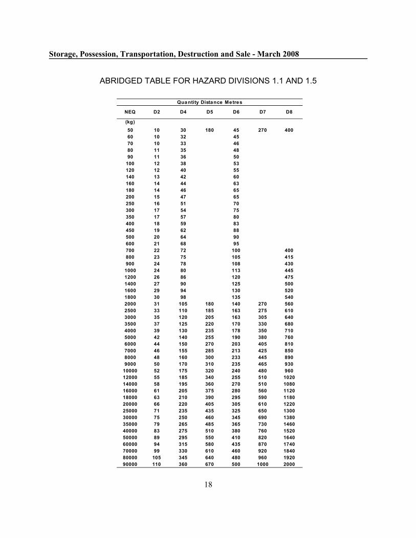
'������)*���������)��������������)�����( ������+'���,# �� -"../
�0
����������������������������������������������
����
�� �� �� �� � ��� ��
� �� �� �
�� �� ��
� �� ��
�� �� � ��
��� �� � ��
��� �� � ��
�� �� � �
� � � �
�� � �
��� �� � �
��� � �� ��
��� �� � ��
��� �� �� �
�� � �� �
�� �� �
��� �� ��
�� �� ��
��� �� �� ��� ��
�� �� �� ��� ��
��� � � �� ��
���� � � ��� �
���� � ��� ��
��� �� �� ��� ���
� �� �� � ��� ���
��� �� � ��� ��
���� �� ��� �� �� ��� � �
���� �� ��� �� � � ��� ��
���� �� ��� ��� � � ��� �
���� �� ��� ��� ��� ��� �
��� �� ��� ��� �� ��� ���
���� � �� ��� ��� �� � �
��� ��� ��� ��� �� ��
���� ��� �� ��� �� ��
��� � � ��� ��� � ��
���� �� ��� ��� ��� � ���
����� �� ��� ��� �� � � �
����� �� �� �� ��� ��� ����
���� � ��� � � ��� ��� ���
� ��� � ��� ��� �� � � ����
���� � ��� ��� ��� ��� ���
����� ��� �� ��� �� ����
����� �� ��� �� ��� �� ����
����� �� ��� � �� �� ���
����� �� � � � � � ��� � �
���� � ��� ��� �� � � ����
����� � ��� ��� �� �� � �
���� � ��� �� �� �� ���
����� �� ��� �� � ��� ��
���� ��� �� � � � � ����
����� ��� � � �� ��� ���� ����
������������������������
�� � �� �� �� ���

�3
$����+��7
'$#*1�:��# �:�=�����A!�����1'?���
�� �!"���#� ��$%&
'($�)*#���+*("'#"$�,&
+-�..�/�#01
�(����2�/�3�04
"� $)#
�5'6$+"7�+�"�7��#$(8
,�'�0/����/�����.��0�9����-����:���/���4 �9��������-9���;��0<�������/��9�/��0���0����.�9�=����-�
��/�.���0/9����%
��#� +" ��#)(�
+#$*>
?�6��*�
KIGGAVIK PROJECT DRILLING AND BLASTING DESIGN
April 26, 2011 Report No. 10-1345-0026 Task 3 rev
APPENDIX B Nunavut Mine Health Safety Regulations

MINE HEALTH AND SAFETY ACT LOI SUR LA SANTÉ ET LA SÉCURITÉ DANSLES MINES
CONSOLIDATION OF MINE HEALTHAND SAFETY REGULATIONSR-125-95
CODIFICATION ADMINISTRATIVEDU RÈGLEMENT SUR LA SANTÉET LA SÉCURITÉ DANS LESMINESR-125-95
AS AMENDED BY MODIFIÉ PARR-026-97R-106-97R-041-98R-026-99
R-026-97R-106-97R-041-98R-026-99
This consolidation is not an official statement of the law.It is an office consolidation prepared for convenience ofreference only. The authoritative text of regulations canbe ascertained from the Revised Regulations of theNorthwest Territories, 1990 and the monthlypublication of Part II of the Northwest TerritoriesGazette (for regulations made before April 1, 1999) andPart II of the Nunavut Gazette (for regulations made on orafter April 1, 1999).
La presénte codification administrative ne constitue pasle texte officiel de la loi; elle n’est établie qu'à titredocumentaire. Seuls les règlements contenus dans lesRèglements révisés des Territoires du Nord-Ouest(1990) et dans les parutions mensuelles de la Partie II dela Gazette des Territoires du Nord-Ouest (dans le casdes règlements pris avant le 1 avril 1999) et de la Partieer
II de la Gazette du Nunavut (dans le cas des règlementspris depuis le 1 avril 1999) ont force de loi.er
250
R-026-99,s.52. gel ou tout autre explosif au nitrate d'ammoniumrelativement insensible. (blasting agent)
«trou de sautage» S'entend d'un trou foré dans le but d'yplacer et d'y faire sauter des explosifs. (blasthole)R-026-99, art. 52.
MAGAZINES DÉPÔTS
Explosive Magazines Dépôts d'explosifs
14.02. The manager shall(a) obtain an explosives magazine permit from
the chief inspector before a magazine islocated, erected, built and put into serviceor modified;
(b) ensure that a magazine is not put intoservice until an explosives magazine permithas been issued;
(c) ensure that a copy of the explosivesmagazine permit is posted inside themagazine; and
(d) ensure that the magazine meets therequirements of regulations and standardsmade under the Explosives Act (Canada),as amended from time to time.R-026-99,s.53.
14.02. Le directeur :a) reçoit un permis de dépôt d'explosifs de
l'inspecteur en chef avant que le dépôt nesoit localisé, érigé, construit et mis enservice ou modifié;
b) fait en sorte que le dépôt ne soit mis enservice avant la délivrance du permis dedépôt d'explosifs;
c) fait en sorte qu'une copie du permis dedépôt d'explosifs soit affichée à l'intérieurdu dépôt;
d) fait en sorte que le dépôt respecte lesexigences des règlements et normes pris envertu de la Loi sur les explosifs (Canada),dans sa version la plus récente. R-026-99,art. 53.
Surface Magazines Dépôts en surface
14.03. (1) Subject to subsection (2), the site for a surfacemagazine shall be selected in accordance with theQuantity-Distance Table For Blasting Explosives.
14.03. (1) Sous réserve du paragraphe (2), le lieu d'undépôt en surface doit être choisi en conformité avec letableau des distances en fonction des quantitésd’explosifs.
(2) The manager may apply to the chief inspectorfor a variance where it is not possible to comply with theQuantity-Distance Table For Blasting Explosives.
(2) Le directeur peut demander une dérogation àl'inspecteur en chef s'il n'est pas possible de se conformerau tableau des distances en fonction des quantitésd’explosifs.
(3) The manager shall ensure that a surfacemagazine ceases to be used if the conditions under whichthe explosives magazine permit was issued no longerexist.
(3) Le directeur fait en sorte que le dépôt en surfacecesse d'être utilisé si les conditions en vertu desquelles lepermis de dépôt d'explosifs a été délivré ne sont plusremplies.
(4) The manager shall ensure that "NO SMOKINGOR OPEN FLAME" signs are posted at all approaches toa magazine.
(4) Le directeur fait en sorte que des panneaux "NEPAS FUMER OU PAS DE FLAMME NUE" soientaffichées à tous les accès d'un dépôt.
(5) No person shall smoke, take an open flame or (5) Nul ne fume, ne tient une flamme nue ou ne
251
produce sparks within 20 m of any place whereexplosives are stored or handled.
produit d'étincelles à moins de 20 m de tout endroit oùsont stockés ou manipulés des explosifs.
(6) Explosives stored on the surface shall be kept ina magazine with "DANGER EXPLOSIVES" signsconspicuously posted at all approaches to the magazineand on each side of the magazine.
(6) Les explosifs stockés à la surface doivent l'êtredans un dépôt sur lequel et aux accès duquel sont affichésbien en vue des panneaux indiquant «DANGEREXPLOSIFS».
(7) Magazines shall be kept securely locked at alltimes except when an authorized person is present.R-026-99.s.54.
(7) Les dépôts sont tenus fermés sécuritairement entout temps sauf en présence d'une personne autorisée. R-026-99, art. 54.
Electrical, Heating and Lighting Électricité, chauffage et éclairage
14.04. In each magazine or area where explosives areprepared,
(a) electrical equipment and wiring shall meetthe requirements of CSA StandardCAN/CSA M421-93, Use of Electricity inMines;
(b) electrical wiring shall be installed in metalarmour or rigid metal conduit havingscrewed, waterproof joints; and
(c) cable armouring and conduit shall bepermanently grounded. R-026-99,s.55.
14.04. Dans tout dépôt ou tout lieu où sont préparés desexplosifs :
a) l'équipement et les canalisations électriquesrespectent les exigences de la normeCAN/CSA M421-93 intitulée Utilisationde l'électricité dans les mines;
b) les canalisations électriques sont installéesdans une armature ou un conduit en métalavec des joints vissés étanches;
c) l'armature et le conduit des câbles sontenterrés de façon permanente. R-026-99,art. 55.
14.05. Where a magazine or area where explosives areprepared is electrically heated, lighted or provided with atelephone,
(a) electrical fuses or circuit breakers shall beinstalled in a locked fireproof cabinetlocated outside the room in whichexplosives are stored;
(b) electrical fuses or circuit breakers forheating circuits shall interrupt the currentwhere it is 25% over the normal load;
(c) where a liquid is used as a heating medium,the radiation pipes shall be effectivelygrounded;
(d) electrical fuses for lighting circuits shall notbe rated at more than 10A; and
(e) lighting fixtures shall be suitable for ClassII, Division 2 locations.
14.05. Lorqu'un dépôt ou un lieu de préparation desexplosifs est chauffé électriquement, éclairé ou pourvud'un téléphone :
a) des fusibles électriques doivent êtreinstallés dans un coffret fermé à l'épreuvedu feu à l'extérieur de la pièce dans laquellesont stockés les explosifs;
b) les fusibles ou les coupes circuits descircuits de chauffage doivent couper lecourant lorsque celui-ci est 25 % au-dessusde la normale;
c) lorsque le chauffage s'effectue par liquide,les tuyaux de chauffage doivent êtreenterrés efficacement;
d) les fusibles des circuits électriques nedoivent pas être supérieurs à 10A;
e) les accessoires d'éclairage sont adaptés àdes endroits de type classe 2, division 2.
14.06. Overhead power lines supplying electricity to amagazine or area where explosives are prepared shall
(a) be protected against power surges andlightning; and
14.06. Les lignes aériennes d'électricité approvisionnantle dépôt ou le lieu de préparation des explosifs enélectricité :
a) sont protégées contre les surtensions et la
252
(b) be terminated in a cable a minimum of 60 mhorizontal distance from the magazine.
foudre;b) sont terminées dans un câble situé à une
distance horizontale minimum de 60 m dudépôt.
14.07. All metal parts of a magazine or area whereexplosives are prepared such as framing, cladding, piping,cable armour and any electrical components shall bepermanently bonded to ground in accordance with therequirements of CSA Standard C22.1-94, CanadianElectrical Code, Part I.
14.07. Toutes les parties métalliques du dépôt ou le lieude préparation des explosifs telles que la charpente, legainage, le tubage, l'armature des câbles et tous lescomposants électriques sont attachés au sol de façonpermanente en conformité avec les exigences de laPremière partie du Code canadien de l'électricité(C22.1-94).
Magazine Care and Use Entretien et utilisation du dépôt
14.08. (1) Each magazine shall be operated andmaintained in accordance with the following rules:
(a) the magazine shall be in the charge of anauthorized person who shall carry out aweekly inspection of the magazine andrecord the results in a log-book;
(b) at a mine site, a record shall be kept of allexplosives issued and received and of theinventory of the surface magazine in a log-book, and all entries shall be signed by theauthorized person;
(c) the magazine shall be kept clean, dry, andfree from grit at all times and any spillageshall be cleaned up immediately;
(d) where necessary, the shelves and floorsshall be treated with a suitable neutralizingagent to remove all traces of explosivesubstances;
(e) the contents, including any explosivesreturned from a work place, shall bearranged in a tidy and organized manner;
(f) the magazine shall not contain any exposediron or steel except in fixtures;
(g) an authorized person shall ensure that thestock of explosives is rotated so that theoldest stock of each type and size ofexplosive is used first.
14.08. (1) Tout dépôt est exploité et entretenu enconformité avec les règles suivantes :
a) il est placé sous le contrôle d'une personneautorisée qui effectue une inspectionhebdomadaire du dépôt dont elle enregistreles résultats dans un registre;
b) dans un chantier minier, un relevé de tousles explosifs distribués et reçus ainsi quel’inventaire du contenu du dépôt de surfaceest tenu dans un registre et toutes lesentrées sont signées par la personneautorisée;
c) il est tenu propre, sec et sans grenaille entout temps et tout deversement estimmédiatement nettoyé;
d) lorsque nécessaire, les étagères et le solsont traités avec un agent neutralisantadapté pour enlever toute trace desubstances explosives;
e) ce qui s'y trouve est rangé de manièreorganisée y compris les explosifs retournésd'un lieu de travail;
f) il ne contient aucun fer ou acier nu saufdans les élements fixes;
g) une personne autorisée s'assure de larotation du stock de manière à ce que lestock le plus vieux pour chaque type etchaque taille d'explosif soit utilisé enpremier.
(2) The ground surrounding a magazine must bekept free of all brush, timber or other combustiblematerial for a distance of not less than 20 m from themagazine. R-026-99,s.56.
(2) Le sol entourant le dépôt doit être libre de touscopeaux, grumes ou autres matériaux combustibles dansun rayon d'au moins 20 m. R-026-99, art. 56.
253
UNDERGROUND STORAGE STOCKAGE SOUTERRAIN
Explosives Explosifs
14.09. Explosives underground in a mine shall be storedin a magazine, on day benches or in suitable shift boxes.R-026-99,s.57.
14.09. Les explosifs souterrains, dans une mine, sontstockés dans un dépôt, des coffres journaliers ou dans desboîtes de poste qui conviennent. R-026-99, art.57.
14.10. Detonators underground in a mine shall be storedin a magazine or in suitable shift containers.R-026-99,s.58.
14.10. Les détonateurs souterrains, dans une mine, sontstockés dans un dépôt ou dans des contenants de posteadaptés. R-026-99, art. 58.
Permits Permis
14.11. (1) The manager shall apply to the chief inspectorfor a permit to store more than 300 kg of explosives in anunderground magazine.
14.11. (1) Le directeur demande un permis à l'inspecteuren chef pour stocker plus de 300 kg d'explosifs dans undépôt souterrain.
(2) The application shall contain a plan of thelocation and the specification of the magazine.
(2) La demande contient un plan des lieux et lescaractéristiques du dépôt.
(3) Where the chief inspector is satisfied with theplan of the location, the chief inspector may issue apermit to the applicant.
(3) L'inspecteur en chef qui est satisfait du plan deslieux peut délivrer un permis au demandeur.
(4) Explosives shall be stored in a magazine inaccordance with the requirements established by the chiefinspector.
(4) Les explosifs sont stockés dans un dépôt enconformité avec les exigences mises en place parl'inspecteur en chef.
(5) Where explosives loading operations areconducted continuously over successive shifts, thequantity of explosives required for the completion of theoperation may be stored near the loading site without apermit. R-026-99,s.59.
(5) Lorsque des opérations de chargementd’explosifs se poursuivent pendant plusieurs postesconsécutifs, la quantité d'explosifs nécessaire à laréalisation complète de l'opération de chargement peutêtre stockée près du lieu de chargement sans permis.R-026-99, art. 59.
Storage of Detonators Underground Stockage souterrain des détonateurs
14.12. (1) The manager shall apply to the chief inspectorfor a permit to store detonators in a magazine.
14.12. (1) Le directeur demande un permis à l'inspecteuren chef pour stocker des détonateurs dans un dépôt.
(2) Repealed, R-026-99,s.60. (2) Abrogé, R-026-99, art. 60.
(3) The application for a permit to store detonatorsshall contain a plan of the location and the specificationsof the construction of the magazine.
(3) La demande comprend un plan du lieu et lescaractéristiques de la construction du dépôt.
(4) Detonators shall be stored in a magazine inaccordance with requirements established by the chiefinspector.
(4) Les détonateurs stockés dans un dépôt sontstockés en conformité avec les exigences mises en placepar l'inspecteur en chef.
254
(5) The magazine shall not be within 20 m of anylocation where other explosives are stored.
(5) Le dépôt ne doit pas se trouver à moins de 20 mde tout lieu où sont stockés d'autres explosifs.
(6) Where the chief inspector is satisfied with theplan of the location and the specifications of theconstruction, the chief inspector may issue a permit to theapplicant. R-026-99,s.60.
(6) L'inspecteur en chef qui est satisfait du plan deslieux et des caractéristiques de la construction peutdélivrer un permis au demandeur. R-026-99, art.60.
Location of Explosives Storage Lieu de stockage des explosifs
14.13. A magazine, day bench, shift box or shiftcontainer shall be
(a) located at least 60 m from a shaft, hoistroom, refuge station, transformer vault,electrical substation or fuel storage area;
(b) provided with conspicuous signs marked"EXPLOSIVES" in letters at least 150 mmin height; and
(c) provided with conspicuous "NOSMOKING OR OPEN FLAME" signsvisible from all approaches and placed notless than 20 m from the magazine, daybench, shift box or shift container.R-026-99,s.61.
14.13. Un dépôt, un coffre journalier, une boîte de posteou un contenant de poste doit être :
a) situé à 60 m au moins d'un puit, d'une sallede machine d'extraction, d'un abri, d'unechambre de transformateur, d'une sous-station électrique ou d'un dépôt de fuel;
b) pourvu de panneaux bien en vue surlesquels sont inscrits «EXPLOSIFS» enlettres d'une taille non inférieure à 150 mm;
c) pourvu de de panneaux visibles de tous lesabords sur lesquels sont inscrits «NE PASFUMER OU PAS DE FLAMME NUE»dans un rayon de 20 m autour d'un dépôt,d'un coffre journalier, d'une boîte ou d'uncontenant de poste. R-026-99, art. 61.
Day Bench or Shift Box Location Emplacement du coffre journalier oude la boîte de poste
14.14. (1) A day bench or shift box shall be located in anarea that is acceptable to an inspector, free of water, andfree from risk of any train, car or haulage colliding withthe explosives.
14.14. (1) Le coffre journalier ou la boîte de postedoivent être situés dans un lieu sec acceptable par uninspecteur, et sans risque de collision de train, de berlineou de transport avec les explosifs.
(2) A day bench or shift box shall be constructed orplaced at least 1 m above floor level where thesurrounding strata is adequately secured and shall, wherenecessary, have floors and walls lined with non-sparkingmaterial.
(2) Le coffre journalier ou la boîte de poste doiventêtre construits ou placés au moins 1 m au dessus du sol oùles strates environnantes sont protégées adéquatement et,lorsque nécessaire, dont les sols et les murs sont doublésde matériau qui ne provoque pas d'étincelles.
Weekly Inspection Inspection hebdomadaire
14.15. The manager shall authorize and require one ormore qualified persons to make a thorough weeklyinspection of all magazines, day benches, shift boxes orshift containers used for storing explosives or detonatorsand to report, in writing, to the manager stating that therequired inspection has been made and indicating theconditions found. R-026-99,s.62.
14.15. Le directeur autorise une ou plusieurs personnesqualifiées à procéder à une inspection hebdomadaire detous les dépôts, coffres journaliers, boîtes de poste oucontenants de poste utilisés pour stocker des explosifs oudes détonateurs et de rapporter au directeur en précisantque l'inspection exigée a été faite et l'état dans lequel ilsse trouvent. R-026-99, art. 62.
255
Blasting Certificate Certificat de sautage
14.16. (1) No person shall prepare or conduct or beallowed to prepare or conduct a blasting operation in orabout a mine unless that person holds a blastingcertificate issued by the chief inspector or a provisionalblasting certificate issued by the manager.
14.16. (1) Nul ne peut préparer, conduire ou être autoriséà préparer ou diriger un travail de sautage dans ou prèsd'une mine à moins d'être titulaire d'un certificat desautage delivré par l'inspecteur en chef ou d'un certificatde sautage provisoire délivré par le directeur.
(2) Notwithstanding subsection (1), a person who isnot the holder of a blasting certificate may assist in thepreparation and firing of charges if he or she does sounder the immediate direction and supervision of a personwho holds a blasting certificate.
(2) Par dérogation au paragraphe (1), une personnequi n'est pas titulaire d'un certificat de sautage peut aiderà la préparation et à la mise à feu des charges si elle le faitsous la direction et le contrôle d'une personne titulaired'un certificat de sautage.
(3) The blaster shall deliver his or her blastingcertificate to the manager when he or she commencesemployment as a blaster at the mine, and the managershall, unless the certificate has been suspended, return itto the blaster when his or her employment is terminated.
(3) Le boutefeu dépose son certificat de sautageauprès du directeur lorsqu'il commence son travail en tantque boutefeu à la mine et le directeur, à moins que lecertificat n'ait été suspendu, le lui rend lorsque son emploiest terminé.
Fume Class Catégorie de fumée
14.17. (1) Subject to subsection (2), explosives used inan underground mine shall be of Fume Class I rating asestablished by the Explosives Branch of the Departmentof Natural Resources, (Canada).
14.17. (1) Sous réserve du paragraphe (2), les explosifsutilisés dans une mine souterraine doivent être notésfumée de classe I par la direction des explosifs duministère de l'Énergie, des mines et des ressources duCanada.
(2) Before explosives other than explosives of FumeClass I rating are used in an underground mine, themanager shall apply to the chief inspector for permissionto use such explosives, and the application shall containdetails of the procedures to be taken to ensure that noperson is exposed to fumes and gases that endanger his orher health.
(2) Avant de pouvoir utiliser dans une minesouterraine d'autres explosifs que ceux notés fumée declasse I, le directeur demande l'autorisation d'utiliser detels explosifs à l'inspecteur en chef. La demande doitcontenir les détails de la marche à suivre devant être priseafin de faire en sorte que personne ne soit exposée à desfumées ou des gaz qui peuvent menacer sa santé.
(3) The manager shall give a copy of an applicationunder subsection (2) to the Committee.
(3) Le directeur donne au comité une copie de lademande faite en vertu du paragraphe (2).
(4) Where the chief inspector is satisfied that theprocedures to be taken to ensure that no person is exposedto fumes and gases that may endanger health, the chiefinspector may give permission to use explosives otherthan explosives of Fume Class I rating in an undergroundmine.
(4) Lorsque l'inspecteur en chef est satisfait desmarches à suivre devant être prises afin de faire en sorteque personne ne soit exposée à des fumées ou des gaz quipeuvent menacer la santé, il peut donner l'autorisationd'utiliser dans une mine souterraine d'autres explosifs queceux notés fumée de classe I. R-026-97, art. 11.
Prohibitions Interdiction
14.18. No person shall possess any explosives ordetonators except as required in the performance of his or
14.18. Il est interdit d'être en possession d'explosifs ou dedétonateurs en dehors de l'exercice de ses fonctions à la

256
her duties at the mine. mine.
14.19. No person shall remove, or be permitted toremove, explosives or detonators from a mine without aspecific written authorization given by the manager inrespect of each occurrence.
14.19. Il est interdit de sortir ou d'être autorisée à sortirdes explosifs ou des détonateurs de la mine sansautorisation expresse écrite du directeur à chaque fois quenécessaire.
Frozen Explosives Explosifs congelés
14.20. Frozen explosives shall only be thawed inaccordance with a procedure established by the managerin accordance with the manufacturer's recommendations.
14.20. Les explosifs congelés sont seulement dégelés enconformité avec la marche à suivre mise en place par ledirecteur selon les recommandations du fabricant.
Careless Acts Actes négligents
14.21. (1) No person shall commit a careless act withexplosives or detonators.
14.21. (1) Il est interdit de commettre des actesnégligents avec des explosifs ou des détonateurs.
(2) A person who discovers that a careless act hasbeen committed involving explosives or detonators shallreport the incident without delay to his or her shift boss,who shall report the matter without delay to his or hersupervisor.
(2) Toute personne qui découvre qu'un actenégligent avec des explosifs ou des détonateurs a étécommis doit le rapporter immédiatement à son chef deposte qui rapporte le problème à son surveillant.
(3) A supervisor who receives a report of a carelessact involving explosives or detonators shall, withoutdelay, report the incident to the manager.
(3) Le surveillant qui reçoit un rapport d'un actenégligent avec des explosifs ou des détonateurs enrapporte les détails au directeur.
(4) A manager who receives a report of a carelessact involving explosives or detonators shall make aninitial verbal report without delay to the chief inspectorand the Committee, and shall provide a written reportwithin 24 hours of the incident.
(4) Le directeur qui reçoit un rapport d'un actenégligent avec des explosifs ou des détonateurs rapportecelui-ci à l'inspecteur en chef et au comité, verbalementtout d'abord, puis par écrit dans les 24 heures.
Opening of Containers Ouverture des contenants
14.22. Only implements made of non-sparking materialshall be used to open boxes containing nitro-glycerinebased explosives.
14.22. Les caisses contenant des explosifs à base denitroglycérine doivent être ouvertes avec des outils faitsde matériaux qui ne produisent pas d'étincelles.
Defective Explosives Explosifs défectueux
14.23. (1) A person who discovers explosives he or shebelieves to be defective shall not use them and shall,without delay, report to the shift boss or supervisor.
14.23. (1) La personne qui découvre tout explosif qu’ellecroit défectueux ne doit pas les utiliser et en rapporteimmédiatement au chef de poste ou au surveillant.
(2) The shift boss or supervisor shall, without delay,report the defective explosives to the manager.
(2) Le chef de poste ou le surveillant en rapporte audirecteur sans délai.
(3) The manager shall (3) Le directeur :
257
(a) report the matter to an inspector and to themanufacturer of the explosives, with asmuch batch identification data as isavailable; and
(b) ensure that the explosives are removed anddestroyed in a safe manner in accordancewith the manufacturer’s recommendations.
R-026-99,s.63.
a) rapporte le problème à un inspecteur et aufabricant des explosifs accompagné dumaximum de renseignements disponiblessur le lot;
b) fait en sorte que les explosifs soient retiréset détruits en toute sécurité en conformitéavec les recommandations du fabricant.
R-026-99, art. 63.
Cartridge Wrapper Emballage des cartouches
14.24. Cartridge explosives, other than water-gel oremulsion explosives that are to be used for blastingoversize rock or bringing down hung-up material, shallnot be removed from their wrappers.
14.24. Les cartouches d'explosif, autre que les explosifsen bouillie ou les émulsions explosives utilisées pour lesautage des roches de grandes dimensions ou pour fairedescendre les produits d'abattage bloqués, ne doivent pasêtre retirées de leur emballage d'origine.
Prohibition Interdiction
14.25. (1) No person shall use safety fuse, otherwiseknown as tape fuse, in any blasting operations at a mine.
14.25. (1) Il est interdit d'utiliser des mèches de sûretéégalement connues sous le nom de mèche plate, pour lestravaux de sautage dans une mine.
(2) The manager shall ensure that safety fuse is notpresent at a mine.
(2) Le directeur fait en sorte qu'aucune mèche desûreté ne soit présente dans la mine.
Transporting Explosives Transport des explosifs
14.26. Explosives and detonators at a mine shall becarried or transported in accordance with theseregulations.
14.26. Les explosifs et les détonateurs dans une minedoivent être portés ou transportés en conformité avec leprésent règlement.
14.27. Repealed, R-026-99,s.64. 14.27. Abrogé, R-026-99, art. 64.
14.28. Detonators, if not used, shall be returned to thedetonator magazine or shift box or shift container but thenumber of detonators in a shift box or shift container mustnot exceed 50. R-026-99,s.65.
14.28. Les détonateurs non utilisés doivent être retournésau dépôt de détonateurs, dans la boîte de poste ou lecontenant de poste mais le nombre de détonateurscontenus dans la boîte de poste ou dans le contenant deposte ne doit pas être supérieur à 50. R-026-99, art. 65.
Transportation of Explosives and Detonators Transport des explosifs et des détonateurs
14.29. Mobile equipment used for transportingexplosives on the surface shall
(a) be kept in sound mechanical condition;(b) when carrying explosives, be provided with
orange diamond-shaped placards and withc lea rly vi s ibl e s i g n s marked"EXPLOSIVES" in letters not less than 150mm in height;
14.29. Un équipement mobile, de transport des explosifsen surface dans une mine :
a) doit être tenu en bon état mécanique;b) doit être équipé de plaques de danger en
forme de diamant de couleur orange et depanneaux indiquant de manière clairementvisible «EXPLOSIFS» en lettre n'ayant pasmoins de 150 mm de hauteur;

258
(c) have all metal parts that could come incontact with containers of explosivescovered with wood, tarpaulin or similarnon-sparking material;
(d) not be used to transport other goods ormaterials at the same time as explosives aretransported;
(e) be equipped with a type 20-ABC fireextinguisher;
(f) not be loaded with explosives in excess of80% of its rated carrying capacity;
(g) have explosives secured or fastened so as toprevent any part of the load from becomingdislodged;
(h) transport detonators with other explosivesonly if the detonators are
(i) packed in their original containers andplaced in a wooden box with a snuglyfitting lid that is separated from otherexplosives by a solid partition of woodat least 150 mm thick and that extendsat least 150 mm above the highestlevel to which the explosives arepacked in the vehicle, and
(ii) 5,000 or fewer in number;(i) only be operated by an authorized person
who is in attendance at all times;(j) carry only those persons necessary for
handling explosives;(k) not be refuelled if explosives or detonators
are on board except where the mobileequipment is designed and used solely forthe transportation of bulk blasting agents;and
(l) have its engine shut off and its park brakeon while loading or unloading explosives,except where the vehicle uses an engine-powered device for loading and unloadingthe explosives. R-026-99,s.66.
c) doit avoir toutes les parties métalliques quipourraient venir en contact avec lesconteneurs d'explosifs couverts de bois,d'une bâche ou de tout autre matériau qui neproduit pas d'étincelles;
d) ne doit pas être utilisé pour transporterd'autres biens ou matériels en même tempsque des explosifs;
e) doit être équipé d'un extincteur de type20-ABC;
f) ne doit pas être chargé avec des explosifs àplus de 80 % de sa masse brute maximale;
g) doit avoir les explosifs arrimés ou attachésafin d'éviter que toute partie du chargementne se détache;
h) ne doit transporter des détonateurs avecd'autres explosifs que si les détonateurssont :
(i) emballés dans leur contenant d'origineet rangés dans une boîte en bois aucouvercle parfaitement adapté, séparéedes autres explosifs par une cloison debois épaisse d'au moins 150 mm et quidépasse de 150 mm au moins le pointle plus haut auquel les explosifs sontchargés dans le véhicule,
(ii) moins de 5 000 en nombre;i) ne peut être conduit que par une personne
autorisée et qui doit être présente en touttemps;
j) ne peut transporter que les personnesnécessaires à la manutention des explosifs;
k) ne doit pas être ravitaillé en carburantlorsqu’il porte des explosifs ou desdétonateurs sauf s’il s’agit d’un équipementmobile conçu et utilisé exclusivement autransport de substances explosives en vrac;
l) doit avoir son moteur arrêté et son frein àmain serré pendant le chargement et ledéchargement des explosifs sauf lorsque levéhicule utilise un dispositif, dont l'énergievient du moteur, pour charger et déchargerles explosifs. R-026-99, art. 66.
14.30. (1) The transfer of explosives or detonators froman explosives magazine shall be so arranged that no delayoccurs between the time the explosives or detonatorsleave the magazine and the time they are properly storedin designated underground magazines or distributed topoints of use.
14.30. (1) Le transport d'explosifs ou de détonateurs d'undépôt d'explosifs doit être préparé de façon à ce qu'aucunretard n'intervienne entre le moment où les explosifs oules détonateurs quittent le dépôt et le moment où ils sontstockés dans les dépôts souterrains ou distribués auxendroits d'utilisation.
259
(2) Explosives shall not be left at any level stationor near the collar or other entrance to the mine, but shallbe transferred to designated magazines or points of usewithout delay.
(2) Les explosifs ne doivent être laissés à aucunerecette de niveau ni près de l'orifice du puit mais doiventêtre transportés sans retard aux dépôts désignés ou auxendroits d'utilisation.
(3) At no time shall explosives be left unattendedduring transportation. R-026-99,s.67.
(3) À aucun moment durant le transport, lesexplosifs ne doivent rester sans surveillance. R-026-99,art. 67.
14.31. (1) When explosives are to be transported in aconveyance, the authorized person in charge of theoperation shall give notice of that fact to the hoistoperator and, as applicable, to the shaft supervisor andcage tender.
14.31. (1) Lorsque des explosifs doivent être transportésdans un transporteur, la personne autorisée chargée del'opération en avise le machiniste d'extraction et, selon lecas, le surveillant du puit et le préposé à la cage.
(2) Explosives shall not be loaded into, transportedin or unloaded from a conveyance unless there is anauthorized person in charge.
(2) Les explosifs ne doivent pas être chargés outransportés dans un transporteur ou déchargés d'untransporteur sans la présence d'une personne autoriséechargée de l'opération.
(3) No materials shall be carried in the sameconveyance as explosives.
(3) Il est interdit de transporter dans un mêmetransporteur des explosifs et des matériaux.
(4) No persons shall be transported in a conveyancewhile explosives are being transported in the same shaft,except that persons may be transported in the conveyancefor the sole purpose of handling the explosives.
(4) Il est interdit de transporter des personnes dansun transporteur alors que des explosifs sont transportés enmême temps dans le même puits, à l'exception despersonnes nécessaires à la manutention des explosifs.
(5) Explosives that have been delivered to a headframe or portal shall be transported undergroundimmediately on the approach of an electrical storm.
(5) Tous les explosifs qui ont été délivrés à unchevalement ou une entrée de galerie doivent êtretransportés sous terre immédiatement à l'approche d'unorage électrique.
(6) Explosives shall not be transported in a shaftduring an electrical storm.
(6) Il est interdit de transporter des explosifs dans unpuits lors d'un orage électrique.
14.32. Where explosives or detonators are transportedunderground on a train,
(a) the locomotive shall be maintained on theforward end of the train, and no explosivesor detonators shall be carried on thelocomotive;
(b) a car carrying explosives or detonators shallbe
(i) separated from the locomotive by anempty car or a spacer of equivalentlength, and
(ii) protected from hazards related to thepresence of trolley wires;
(c) the explosives and detonators shall be in
14.32. Lorsque le transport des explosifs ou desdétonateurs sous terre s'effectue sur un train :
a) la locomotive doit rester à l'avant du convoiet ne doit pas transporter d'explosifs ou dedétonateurs;
b) la berline qui transporte les explosifs :(i) doit être séparée de la locomotive par
une berline vide ou une barred'espacement de longueur équivalente;
(ii) être adéquatement protégée contre lesdangers liés à la présence de fils decontact;
c) les explosifs et les détonateurs doivent êtreplacés dans des contenants acceptables par
260
containers that are acceptable to the chiefinspector and that prevent the explosivesand detonators from coming into contactwith any metal that could produce a spark;and
(d) a train carrying explosives or detonators(i) shall only comprise the locomotive,
the empty car or spacer and theexplosive cars, and
(ii) shall not proceed at a speed exceeding10 km/h.
l'inspecteur en chef afin de prévenir toutcontact entre les explosifs ou lesdétonateurs et tout métal qui pourraitproduire une étincelle;
d) le convoi transportant des explosifs ou desdétonateurs ne doit être composé que d'unelocomotive, d'une berline vide ou de laberline d'espacement et des berlinestransportant les explosifs et sa vitesse nedoit pas dépasser 10 km par heure.
14.33. Where explosives or detonators are transportedunderground by means of trackless mobile equipment,
(a) the mobile equipment shall not proceed at aspeed exceeding 10 km/h;
(b) the explosives and detonators shall be incontainers that are acceptable to the chiefinspector and that prevent the explosivesand detonators from coming into contactwith any metal that could produce a spark;
(c) the explosives and detonators shall be soloaded that they cannot fall from the mobileequipment;
(d) the mobile equipment shall, when carryingexplosives, be provided with conspicuoussigns marked "EXPLOSIVES" in letters atleast 150 mm in height;
(e) the mobile equipment shall have its engineshut off and park brake on while loading orunloading explosives or detonators exceptwhere the vehicle uses an engine-powereddevice for loading and unloading theexplosives or detonators;
(f) the mobile equipment shall not be refuelledwith explosives or detonators aboard,except for mobile equipment designed andused solely for the transportation of bulkblasting agents;
(g) no person shall smoke or have an openflame within 20 m of a vehicle transportingexplosives;
(h) the mobile equipment shall not be used totransport other materials at the same time asthe explosives or detonators; and
(i) the mobile equipment shall not carrypersons other than those handling theexplosives and detonators.
14.33. Lorsque le transport souterrain des explosifs oudes détonateurs s'effectue par engin mobile ne sedéplaçant pas sur des rails,
a) la vitesse de l'engin mobile ne doit pasdépasser 10 km par heure;
b) les explosifs et les détonateurs doivent êtreplacés dans des contenants acceptables parl'inspecteur en chef afin de prévenir toutcontact entre les explosifs ou lesdétonateurs et tout métal qui pourraitproduire une étincelle;
c) les explosifs et les détonateurs doivent êtrechargés de manière à ne pas tomber del'engin mobile;
d) lorsqu'il transporte des explosifs, l'enginmobile doit porter des panneaux indiquantde manière clairement visible«EXPLOSIFS» en lettre n'ayant pas moinsde 150 mm de hauteur;
e) l'engin mobile doit avoir son moteur arrêtéet son frein à main serré pendant lechargement et le déchargement desexplosifs ou des détonateurs sauf lorsquecelui-ci utilise un dispositif, dont l'énergievient du moteur, pour charger et déchargerles explosifs;
f) l'engin mobile ne doit pas être ravitaillé encarburant lorsqu'il porte des explosifs oudes détonateurs sauf s'il s'agit d'un enginmobile étudié et utilisé exclusivement autransport de substances explosives en vrac;
g) il est interdit de fumer ou de porter uneflamme nue à moins de 20 m d'un véhiculequi transporte des explosifs;
h) l'engin mobile ne doit pas transporterd'autres matériaux en même temps que desexplosifs ou des détonateurs;
i) il est interdit de transporter sur l'équipement
261
d'autres personnes que celles chargées de lamanutention des explosifs ou desdétonateurs.
Loading and Priming Procedures Marches à suivre pour le chargement et l'amorçage
14.34. (1) Explosives shall not be loaded into a blasthole(a) of insufficient size or in which there is an
obstruction; or(b) by hitting, pounding, ramming or applying
undue pressure.
14.34. (1) Il est interdit de charger d'explosifs un trou demine qui :
a) soit est de taille trop petite ou est obstrué;b) soit doit l'être en frappant, bourrant,
martelant ou en applicant une pressionexcessive.
(2) Explosives shall only be loaded into a blastholeby means of a loading tool made of non-sparkingmaterial.
(2) Les explosifs ne doivent être chargés dans untrou de mine qu'à l'aide d'outils de chargement fait enmatériau qui ne provoque pas d'étincelles.
(3) Primers shall only be made up at the blast site asrequired and shall not be transported.
(3) Les amorces sont préparées sur le lieu desautage, au besoin, et ne doivent pas être transportées.
(4) When priming nitro-glycerine type explosives,only a non-sparking implement shall be used to punch ahole in the explosive.
(4) Lorsque l'amorçage se fait à l'aide d'un explosifde type nitroglycérine, seul un outil ne causant pasd'étincelles doit être utilisé pour faire un trou dansl'explosif.
(5) Every primed explosive shall(a) contain a properly placed detonating device
sufficient to efficiently initiate theexplosion;
(b) in the case of a cartridge explosive, havethe detonator inserted into the cartridge insuch a manner that it cannot be separated orpulled out of the cartridge during theloading operation; and
(c) be detonated at the time for blasting exceptwhere a procedure for doing otherwise hasbeen established by the manager, given tothe Committee and approved by the chiefinspector.
(5) Tout explosif amorcé :a) doit avoir un dispositif détonant
correctement placé et suffisant pour créerl'explosion de façon efficace;
b) lorsqu'il s'agit d'explosif en cartouche, doitavoir un détonateur inséré dans la cartouchede manière à ce qu'il ne peut être séparé ousorti de la cartouche lors de l'opération dechargement;
c) doit être sauté lorsqu'il est amorcé aumoment prévu du sautage sauf si une autremarche à suivre a été préparée par ledirecteur donnée au comité et approuvéepar l'inspecteur en chef.
(6) Where detonating cord is used,(a) loading shall be completed in all holes;(b) all equipment not required for the loading
operation shall be removed from the blastsite before
(i) cords are interconnected betweenholes or attached to trunk line circuits,and
(ii) delay devices or initiating detonatorsare attached to trunk line circuits; and
(6) Lorsqu'un cordon détonant est utilisé :a) le chargement doit être effectué dans tous
les trous;b) tout équipement non exigé pour l'opération
de chargement doit être retiré du lieu desautage avant que :
(i) les cordons ne soient connectés entreles trous ou reliés au circuit réel,
(ii) les dispositifs retardateurs ou lesdétonateurs d'amorçages ne soient
262
(c) the cord shall, for an underground blastingoperation, be connected to the initiatingdetonator as close to the face being blastedas is possible.
reliés au circuit réel;c) il doit, pour une opération de sautage
souterraine, être relié au détonateurélectrique placé le plus près possible dufront de taille qui doit être sauté.
14.35. (1) Where holes are loaded pneumatically withexplosives,
(a) only semi-conductive hoses manufacturedfor such purpose shall be used;
(b) the semi-conductive hose used shall bemaintained to ensure that the conductiveelement is not removed or otherwisedamaged; and
(c) pneumatic loading equipment shall not begrounded directly to pipes, rails or othersimilar continuous conductors.
14.35. (1) Lorsque le chargement des trous s'effectuepneumatiquement :
a) seuls des boyaux semi-conducteursfabriqués dans ce but doivent être utilisés;
b) le boyau semi-conducteur utilisé doit êtreentretenu afin de faire en sorte quel'élément conducteur ne soit pas retiré ouautrement endommagé;
c) l'équipement de chargement pneumatiquene doit pas être mis à la terre par attachedirecte à des tuyaux, des rails ou d'autresconducteurs continus identiques.
(2) Where holes are loaded pneumatically withexplosives and electrical detonators are used,
(a) no plastic or other non-conducting linersshall be used;
(b) a detonator shall not be placed in the holeuntil the pneumatic loading of the hole hasbeen completed, except where a procedurefor doing otherwise has been established bythe manager; and
(c) copies of the procedure have been given tothe Committee and approved by the chiefinspector.
(2) Lorsque le chargement des trous s'effectuepneumatiquement et que des détonateurs électriques sontutilisés :
a) il est interdit d'utiliser des doublures enplastique ou non-conductrices;
b) il est interdit de placer un détonateur dans letrou avant que le chargement pneumatiquedu trou ne soit terminé, sauf si une autremarche à suivre a été préparée par ledirecteur;
c) des copies de la marche à suivre ont étédonnées au comité et approuvées parl'inspecteur en chef.
Guarding Surveillance
14.36. (1) Before a blast is detonated, a person shall bestationed at each entrance or approach to the blast areaand instructed to prevent access to each place where
(a) blasting is to take place;(b) the safety of persons may be endangered by
the blasting; or (c) a diamond drill hole intersection may
connect with the blast.
14.36. (1) Avant chaque sautage, une personne doit êtreplacée à chaque entrée ou aux abords avec instruction deprévenir l'accès à tout endroit où :
a) un sautage va avoir lieub) la sécurité des personnes peut être mise en
danger par le sautage;c) l'intersection d'un trou de sondage au
diamant peut être connectée avec lesautage.
(2) The blaster shall ensure that (a) all persons have vacated the vicinity except
those persons required to assist in blastingand guarding; and
(b) all areas of the mine that may be affected
(2) Le boutefeu doit faire en sorte :a) que personne, à part le personnel chargé
d'assister dans le sautage ou d'assurer lasurveillance, ne se trouve sur les lieux ou àproximité;
263
by the blasting operation are vacated.R-026-99,s.68.
b) que tous les endroits de la mine qui peuventêtre affectés par le sautage aient étéévacués.
R-026-99, art. 68.
14.37. Where contiguous or adjacent claims or mines arebeing worked and there is disagreement as to the timesthat blasting operations should be conducted, the managerof either mine may appeal to the chief inspector who shalldecide the time at which blasting operations may beconducted.
14.37. Lorsque les travailleurs dans des mines ou desconcessions adjacentes ne parviennent pas à s'entendresur l'horaire auquel des opérations de sautage doivent êtreconduites, le directeur de l'une ou l'autre mine peut enappeler à l'inspecteur en chef pour qu'il en fixe l'horaire.
Waiting Time Temps d'attente
14.38. (1) No person shall return to a work place affectedby a blasting operation
(a) where delay action detonators are used anda shot is heard, until 10 minutes haveelapsed from the time the blast is initiated;
(b) until the blaster has disconnected the circuittrunk lines or lead wires from the blastingmachine or power source and has shortcircuited the lines or wires; and
(c) where a blasting switch is employed, untilthe switch is locked in the open position.
14.38. (1) Nul ne peut retourner sur un lieu de travail visépar un travail de sautage avant :
a) l'écoulement de 10 minutes suivant lafermeture du circuit de tir, lorsquel'allumage se fait par des détonateursélectriques à retard et qu'un tir a étéentendu;
b) que le boutefeu n'ait disconnecté les circuitsréels ou les lignes de tir de l'exploseur ou dela source électrique et a court circuité lescircuits ou les lignes;
c) que l'interrupteur de mise à feu ne soitverrouillé en position ouverte, s'il en a étéutilisé un.
(2) Where delay action detonators are used and noshot is heard, no person shall return to the work placeaffected by the blasting operation until the blaster has metthe requirements of paragraphs (1)(b) and (c).
(2) Lorsque sont utilisés des détonateurs électriquesà retard et qu'aucun tir n'est entendu, il est interdit à toutepersonne de retourner sur le lieu de travail visé par lesautage avant que le boutefeu n'ait respecté les exigencesdes alinéas (1)b) et c).
(3) This section does not apply where a centralblasting procedure is in operation.
(3) Le présent article ne s'applique pas lorsqu'unemarche à suivre centrale de sautage est en cours.
14.39. If a person has reason to believe that the gasesproduced during a blasting operation have not beenremoved or diluted to a safe degree by the ventilationsystem, he or she
(a) shall not return to a worksite after theblasting operation; and
(b) shall request the shift boss to test the airwith a suitable instrument and explain theresults to him or her.
14.39. Une personne ne doit pas retourner sur un lieu detravail si elle a des raisons de croire que les gaz produitspar les explosifs n'ont pas été amenés à un niveau sansdanger par le système de ventilation et elle doit demanderau chef de poste de tester l'air à l'aide d'un instrumentadapté et de lui en expliquer les résultats.
Surface Blasting Sautage en surface
264
14.40. (1) The blaster in charge of a blast on the surfaceshall keep a record of each primary blast that includes areport of the following:
(a) the date, time and location of the blast;(b) the burden, spacing, depth and number of
holes blasted;(c) the type of explosives used;(d) the prevailing wind direction and speed at
the time of the blast;(e) the prevailing atmospheric conditions, and
whether it is clear or overcast.
14.40. (1) Le boutefeu chargé d'un sautage à la surfaced'une mine doit tenir un registre de tir de chaque tirprimaire qui doit comprendre :
a) la date, l'heure et le lieu du sautage;b) la disposition, l'espacement, la profondeur
et le nombre de trous sautés;c) le type d'explosif utilisé;d) la direction prédominante et la force du vent
au moment du sautage;e) les conditions atmosphériques
prédominantes, qu'elles soient bonnes oucouvertes.
(2) The blaster in charge of a blast at a surface mineshall ensure that
(a) a warning is given by siren or horn;(b) where necessary, signs are posted to warn
traffic of the impending blast and guards areposted to stop traffic before the blast; and
(c) an all-clear signal is sounded after alldanger from the blast has passed.
R-026-99,s.69.
(2) Le boutefeu chargé d'un sautage à la surfaced'une mine doit faire en sorte :
a) qu'un avertissement soit donné à l'aided'une sirène ou d'un avertisseur;
b) au besoin que des panneaux soient poséspour avertir la circulation de l'imminencedu sautage et que des gardes soient en placeafin d'arrêter la circulation avant le sautage;
c) qu'un signal de laisser-passer soit sonné unefois que tout danger provenant du sautageest écarté.
R-026-99, art. 69.
Blastholes (Surface) Trou de sautage (en surface)
14.41. No mobile equipment shall be allowed within 8 mof any charged blasthole on the surface of a mine except
(a) mobile equipment that is transportingexplosives and that has the exhaust directedabove the cab; or
(b) other mobile equipment authorized inwriting by the chief inspector.
14.41. Aucun engin mobile ne doit être autorisé dans unrayon de 8 m de tout trou de sautage chargé à la surfaced'une mine sauf :
a) l'engin mobile qui transporte des explosifset dont l'échappement est dirigé au-dessusde la cabine;
b) les autres engins mobiles autorisés par écritpar l'inspecteur en chef.
Blasting Machines Exploseurs
14.42. (1) A blasting machine shall(a) be of a type designed and manufactured
specifically for the purpose for which it isused; and
(b) be kept in good mechanical and electricalcondition.
14.42. (1) Un exploseur doit être :a) d'un type spécialement étudié et fabriqué
pour l'objectif qui lui est attribué;b) tenu en bon état mécanique et électrique.
(2) An authorized person shall test the power outputof each blasting machine at the intervals and in themanner established by the manufacturer.
(2) Une personne autorisée doit soumettre tous lesexploseurs aux essais et aux intervalles prescrits par lefabricant pour en vérifier la puissance de sortie.

265
(3) The test results shall be entered in a log-book,dated and signed by the authorized person who conductedthe tests.
(3) Les résultats des essais sont inscrits dans unregistre, datés et signés par la personne autorisée qui aconduit les essais.
14.43. The blaster shall ensure that any residual chargeremaining in the blasting machine after use is dischargedin accordance with the manufacturer's instructions.
14.43. Le boutefeu doit faire en sorte que toute chargerésiduelle soit éliminée après l'utilisation de l'exploseur enconformité avec les prescriptions du fabricant.
Blasting Cables Conducteurs de mise à feu
14.44. Blasting cables and blasting wires shall(a) be clearly distinguishable from other cables
and wires;(b) be used for blasting purposes only;(c) be kept 150 mm from
(i) detonating cords,(ii) power, lighting or communication
cables, and(iii) pipes, rails, ventilation ducting or
other continuous metal groundedcircuits;
(d) be insulated for the maximum voltage thatmay be used; and
(e) be not less than 12 AWG copper wire orthicker, and where expendable connectingwire is used, it shall not be less than 20AWG copper wire.
14.44. Les conducteurs et les câbles de mise à feudoivent être :
a) clairement identifiables des autresconducteurs et câbles;
b) utilisés uniquement aux fins de sautage;c) tenus à 150 mm :
(i) des cordeaux détonants,(ii) des câbles électriques de puissance, du
ci rcui t d ' é c l a i r a g e ou decommunication,
(iii) des tuyaux, rails, des gaines deventilation ou d'autres circuitsmétalliques continus mis à la terre;
d) isolés pour la tension maximale pourlaquelle ils peuvent être utilisés;
e) en cuivre et d'une grosseur d'au moins12 AWG et d'au moins 20 AWG lorsquesont utilisés des câbles de cuivreextensibles.
266
Procedures for Electric Blasting Sautages faits électriquement
14.45. Where blasting is initiated by means of electricity,(a) if more than one shot is to be fired
electrically, the blaster shall, immediatelybefore blasting, test the electrical circuitwith an instrument specifically designedand manufactured for testing blastingcircuits immediately before blasting;
(b) if balanced circuits are required, eachcircuit shall be tested before firing with aninstrument described in paragraph (a);
(c) if electric detonators are used(i) the protective shunt shall not be
removed from the leg wire untilconnections are made,
(ii) the leg wire shall not be shortened,(iii) the blasting circuit trunk lines or lead
wires to the face or faces shall beshort-circuited while the leads fromthe detonators are being connected toeach other and to the blasting leadlines,
(iv) the short-circuit referred to insubparagraph (iii) shall not beremoved until all persons have left theworksites to be affected by theblasting operation, and
(v) the short-circuit referred to insubparagraph (iii) shall be located sothat a premature explosion will notendanger the person opening the short-circuit; and
(d) before any person returns to the worksiteaffected by the blasting operation,
(i) the firing cables shall be removedfrom the battery, blasting machine orother source of electricity and shall beshort-circuited, and
(ii) the blasting switch shall be locked inthe open position.
14.45. Lorsque le sautage est amorcé électriquement :a) et qu'il y a plus d'un tir, le boutefeu doit
essayer le circuit électriqueimmédiatement avant le sautage à l'aided'un instrument spécialement étudié etfabriqué pour l'essai des circuits de sautage;
b) et qu'un équilibrage des circuits est éxigé,chaque circuit doit être essayé avantl'amorçage à l'aide de l'instrument décrit àl'alinéa a);
c) et que des détonateurs électriques sontutilisés :
(i) le dérivateur de protection ne doit pasêtre retiré du fil du détonateur jusqu'aumoment où la connexion est faite,
(ii) les fils du détonateur ne doivent pasêtre raccourcis,
(iii) les circuits réels ou les ligne de tir desautage reliés aux fronts de tailledoivent être court-circuités pendantque les lignes de tir qui partent dudétonateur sont reliées entre elles etaux conducteurs du sautage,
(iv) le court-circuit visé au sous-alinéa (iii)ne doit pas être retiré avant que toutesles personnes n'aient quitté le lieu visépar le travail de sautage,
(v) le court-circuit visé au sous-alinéa (iii)doit être placé de telle façon qu'uneexplosion prématurée est sans dangerpour la personne qui ouvre le court-circuit;
d) et avant que toute personne ne retourne surle lieu de travail visé par le travail desautage :
(i) les câbles de mise à feu doivent êtredéconnectés de la batterie, del'exploseur ou de toute autre sourced'électricité et doivent être court-circuités,
(ii) l'interrupteur de l'exploseur doit êtrevérouillé en position ouverte.
Blasting from Power or Lighting Circuits Sautage à partir du circuit de puissance ou d'éclairage
14.46. (1) Electrical power circuits used for blasting shallbe
(a) from an isolated, ungrounded power source;
14.46. (1) Le circuit électrique de puissance utilisé pourle sautage doit :
a) provenir d'une source isolée et mise à la
267
and(b) used for blasting only.
terre;b) être utilisé uniquement pour le sautage.
(2) An electrical power line blasting switch shall(a) be designed for the purpose for which it is
used;(b) be kept in good condition;(c) be constructed so that it automatically
opens the circuit by gravity to short-circuitthe blasting conductor;
(d) have the live side enclosed within a fixedbox with a door
(i) that can be locked and unlocked onlyby the blaster in charge of the blasting,and
(ii) so arranged that the door cannot beclosed unless the contacts of the firingcircuit are in the opened and shortedposition; and
(e) be electromagnetically operated where thepower source exceeds 300 volts.
(2) Un interrupteur pour la ligne électrique depuissance pour le sautage :
a) est étudié pour l'utilisation qui en est faite;b) est tenu en bon état;c) est construit de façon à ouvrir
automatiquement le circuit par gravité afinde court-circuiter le conducteur du sautage;
d) renferme le conducteur sous tension àmême une boîte fixe avec une porte :
(i) qui ne peut être ouverte ou fermée quepar le boutefeu chargé du sautage,
(ii) placée de telle façon qu'elle ne peutêtre fermée que si les contacts ducircuit de tir sont en position ouverteet court-circuitée;
e) être électromagnétique si la source depuissance est supérieure à 300 volts.
(3) Every electric power line blasting switch shallincorporate a lightning gap of at least 1.5 m between theblasting switch and the service switch, and the gap shallonly be closed by a twist-type plug and cord assemblyimmediately before firing.
(3) Tout interrupteur d'une ligne électrique depuissance de sautage doit comprendre un intervalle deprotection contre la foudre formé par une fiche àmouvement hélicoïdal et raccordé immédiatement avantla mise à feu d'une longueur de 1,5 m entre l'interrupteurde l'exploseur et l'interrupteur de service.
(4) Where a blasting circuit is used for more thanone working place, each branch circuit shall be isolatedby means of a locked isolating switch that automaticallyshort-circuits the branch circuit or by another methodapproved by the chief inspector. R-026-99,s.70.
(4) Lorsque le circuit de sautage est utilisé pour plusd’un lieu de travail, chaque circuit de dérivation doit êtreisolé par un sectionneur verrouillé qui court-circuiteautomatiquement les circuits de dérivation ou par uneautre méthode approuvée par l’inspecteur en chef. R-026-99, art. 70.
Central Blasting Sautage centralisé
14.47. (1) Where a common electrical source is used toinitiate blasts in more than one work place, the managershall
(a) ensure that arrangements are made for(i) the continued shorting of the blasting
cables,(ii) a three-way switch for each individual
blasting circuit that can be locked ineither the shorted or closed position toprovide for shorting, energizing ortesting the circuit, and
(iii) identification of blasting cables and
14.47. (1) Lorsqu'une source électrique commune estutilisée pour l'amorçage de sautage dans plusieurs lieuxde travail, le directeur doit faire en sorte :
a) que des dispositions soient prises pour :(i) la mise en court-circuit continu des
câbles de sautage,(ii) prévoir un interrupteur à trois
positions pour chaque circuit desautage qui peut être vérouillé soit enposition court-circuit, soit en positionouverte afin de prévoir le court-circuitage du circuit, la mise sous
268
switches;(b) establish a blasting procedure
(i) setting out the method of connectingthe blasting circuit trunk lines or leadwires to the electrical supply,
(ii) providing for the evacuation of allpersons from the area of the blast,
(iii) setting out the method of testing thesystem to ensure that the properconnections have been made, and
(iv) providing a layout of the system; and(c) send a copy of the blasting procedure to
each person involved in blasting, to theCommittee and to the chief inspector.
tension du circuit ou l'essai du circuit,(iii) l'identification des câbles de sautage et
des interrupteurs;b) qu'une marche à suivre de sautage précise :
(i) la méthode de connexion des circuitsréels de sautage ou des lignes de tir àla source électrique,
(ii) l'évacuation de toutes les personnes dela zone de l'explosion,
(iii) la méthode d'essai du système quipermet de faire en sorte que lesconnexions correctes ont été faites,
(iv) un plan du système;c) qu'une copie de l'opération de sautage soit
envoyée à toutes personnes qui participentà un sautage, au comité et à l'inspecteur enchef.
(2) Each person involved in blasting shall complywith the blasting procedure.
(2) Quiconque participe à un sautage doit suivre lamarche à suivre.
Electrical Storms Orages électriques
14.48. (1) During an electrical storm or if an electricalstorm appears imminent, the blasting site shall beevacuated and no blasting connections shall be made.
14.48. (1) Pendant un orage électrique ou à l'imminenced'un orage électrique, les lieux du sautage doivent êtreévacués et aucune connexion ne doit être faite.
(2) The manager shall designate a person whoseduty it shall be to make every reasonable effort to notifyunderground workers of an electrical storm.
(2) Le directeur doit désigner une personne dont latâche est de mettre en oeuvre tout effort raisonnable afind'avertir les travailleurs sous terre de l'orage électrique.
(3) During an electrical storm, no connections shallbe made underground and, if loading and blastingprocedures have commenced, all persons undergroundshall be evacuated to safety in accordance with aprocedure developed by the manager in consultation withthe Committee and acceptable to the chief inspector. R-026-99,s.71.
(3) Pendant un orage électrique, aucune connexionne doit être faite sous terre et si les marches à suivre dechargement et de sautage ont commencé, toutes lespersonnes qui travaillent sous terre doivent être évacuéeset mises à l’abri en conformité avec la marche à suivrepréparée par le directeur, en consultation avec le comitéet jugée satisfaisante par l’inspecteur en chef. R-026-99,art. 71.
Radio Transmitters Émetteurs radioélectriques
14.49. When electrical blasting operations are about to beconducted, no radio frequency transmitter shall beoperated
(a) in a surface mine, within 20 m of suchoperations; and
(b) in an underground mine, within the distanceprovided as a standard of safety by CSAStandard Z65-1966, Radiation Hazards
14.49. Lorsque des travaux de sautage par moyenélectrique sont sur le point d'être effectués, aucunémetteur par radiofréquence ne doit être utilisé :
a) dans une mine à ciel ouvert, dans un rayonde 20 m autour de ces travaux;
b) dans une mine souterraine, à la distanceprescrite comme étant la norme de sécuritéétablie par la norme Z65-1966 de la CSA
269
from Electronic Equipment. intitulée Radiation Hazards fromElectronic Equipment.
Drilling Forage
14.50. (1) No person shall commence drilling at a siteunless the exposed face is
(a) subject to section 14.51, washed withwater;
(b) carefully examined for misfires and cut-offholes, giving special attention to bootlegs;and
(c) conspicuously marked with the location ofall misfires and cut-off holes.
14.50. (1) Le forage est interdit dans un lieu avant que lefront de taille exposé :
a) sous réserve de l'article 14.51, n'ait été lavéavec de l'eau;
b) n'ait été soigneusement examiné afin derelever les trous de raté et les trous coupésen accordant une attention spéciale auxculots;
c) n'ait été clairement marqué des trous de ratéet des trous coupés.
(2) No person shall cut chip samples from anexposed face,
(a) until the face has been washed with waterand carefully examined for misfires andcut-off holes; and
(b) within 2 m of any hole containingexplosives.
(2) Il est interdit de couper des échantillons par éclatdu front de taille exposé :
a) avant que celui-ci ait été lavé avec de l'eauet soigneusement examiné afin de releverles trous de raté et les trous coupés;
b) à moins de 2 m d'un trou chargé.
14.51. In a mine where water cannot be used, themanager shall
(a) establish a procedure for checking eachface for misfires and cut-off holes beforedrilling is commenced;
(b) ensure all persons are trained in theprocedure; and
(c) provide a copy of the procedure to theCommittee and to the chief inspector.
14.51. Dans une mine où l'eau ne peut être utilisée, ledirecteur doit :
a) établir une marche à suivre en vue devérifier sur chaque front de taille, avant ledébut du forage, la présence de trous de ratéet de trous coupés;
b) faire en sorte que toutes les personnessoient formées à la marche à suivre;
c) fournir une copie de la marche à suivre aucomité et à l'inspecteur en chef.
14.52. No person shall drill or allow drilling to beconducted
(a) in an underground mine(i) within 150 mm of any part of a
bootleg, or(ii) within 2 m of a misfired hole, a cut-off
hole or a hole containing explosives;and
(b) in a surface mine(i) within 1 m of any part of a bootleg, or
(ii) within 5 m of a misfired hole, a cut-offhole, or a hole containing explosives.R-026-99,s.72.
14.52. Il est interdit de forer ou de permettre de forer :a) dans une mine souterraine, selon le cas :
(i) à moins de 150 mm de toute partied’un culot,
(ii) à moins de 2 m d’un trou de raté, d’untrou coupé ou d’un trou chargé;
b) dans une mine à ciel ouvert, selon le cas :(i) à moins de 1 m de toute partie d’un
culot,(ii) à moins de 5 m d’un trou de raté, d’un
trou coupé ou d’un trou chargé. R-026-99, art. 72.
14.53. No person shall drill within 8 m of a site on a face 14.53. Il est interdit de forer à moins de 8 m du chantier
270
where explosive loading operations are being conducted. d'un front de taille où une opération de chargementd'explosifs est en cours.
14.54. No person shall drill in loose rock produced byblasting unless
(a) the rock has been thoroughly examined toensure that it does not have any holescontaining explosives;
(b) an engineered offset pattern is utilized toprevent overlaying of holes; and
(c) where a hole containing explosives isdiscovered, the drilling is conducted inaccordance with section 14.56.
14.54. Il est interdit de forer dans du roc désagrégé,résultat de sautage à moins :
a) que le roc n'ait été examiné de façonapprofondie afin de faire en sorte qu'il necontienne pas de trous chargés;
b) d'utiliser un patron décalé mis au point afinde prévenir la superposition de trous;
c) que le forage ne soit effectué en conformitéavec l'article 14.56, lorsqu'un trou chargéest découvert.
14.55. Where it is impracticable to make the examinationrequired by paragraph 14.50(1)(b) or to use an offsetpattern as required by paragraph 14.54(1)(b), a remotelycontrolled drilling procedure developed by the managerin consultation with the Committee and acceptable to thechief inspector shall be employed. R-026-99,s.73.
14.55. Une marche à suivre de forage contrôlée àdistance élaborée par le directeur, en consultation avec lecomité et qui satisfasse l’inspecteur en chef doit êtreutilisée lorsqu’il est impossible de procéder à l’examenexigé en vertu de l’alinéa 14.50(1)b) ou d’utiliser unpatron décalé tel qu’exigé en vertu de l’alinéa 14.54(1)b).R-026-99, art. 73.
Misfired Holes Trous de raté
14.56. (1) Where an explosive charge has been misfiredor cut-off, no work may be performed in the area otherthan that required to make the area safe and to deal withthe misfire in accordance with subsection (2).
14.56. (1) Lorsque la mise à feu d'une charge explosivea été ratée ou coupée, aucun autre travail que celui exigépour rendre le lieu sans danger ne doit être effectué dansle secteur en conformité avec le paragraphe (2).
(2) A misfire or cut-off hole shall be(a) reblasted with a fresh primer if necessary;(b) washed out, subject to subsection (3); or(c) dealt with in accordance with subsection (4)
or the procedure established undersubsection (5).
(2) Un trou raté ou coupé doit être :a) soit sauté à nouveau avec une nouvelle
amorce si nécessaire;b) soit lavé, sous réserve du paragraphe (3);c) soit pris en charge en conformité avec le
paragraphe (4) ou avec la marche à suivreétablie en vertu du paragraphe (5).
(3) No person shall wash out an explosive charge thatcontains an explosive that is
(a) nitro-glycerine sensitized;(b) not water soluble; or(c) not described as an explosive that may be
washed out in the procedure establishedunder subsection (5).
(3) Il est interdit de laver pour la retirer du trou unecharge explosive qui contient un explosif qui :
a) soit est sensibilisé à la nitro-glycérine;b) soit n'est pas soluble dans l'eau;c) soit n'est pas désigné dans la marche à
suivre établie en vertu du paragraphe (5)comme étant un explosif qui peut être lavé.
(4) A hole may be drilled for the purpose ofreblasting a missed hole once a shift boss has determined,in consultation with the driller, the location, angle anddepth of the hole to be drilled, and the shift boss shallremain present throughout the drilling of the hole and
(4) Un trou peut être foré dans le but de faire sauterun trou raté, une fois que le chef de poste a déterminé, enaccord avec le foreur, l'endroit, l'angle et la profondeur deforage du trou. Le chef de poste doit rester présent toutau long du forage du trou et ce trou ne peut se trouver à

271
such hole shall not be closer to any part of a missed holethan 150 mm underground or 1 m in a surface operation.
moins de 150 mm pour un travail souterrain ou moins de1 m pour un travail en surface de toute partie du trou raté.
(5) The manager shall prepare a written procedurethat describes the
(a) types of explosives that may be washed outof or removed from a misfired or cut-offhole;
(b) the type of equipment and method to beused; and
(c) the method that may be adopted in blastingrelief holes drilled in accordance withsubsection (4).
R-026-99,s.74.
(5) le directeur doit préparer une marche à suivreécrite qui décrit :
a) le type d'explosif qui peut être lavé ou retirédu trou de raté ou coupé;
b) le type d'équipement et la méthode utilisés;c) la méthode qui peut être utilisée pour le
sautage des trous de dégagement forés enconformité avec le paragraphe (4).
R-026-99, art. 74.
14.57. (1) Work shall not be abandoned or discontinuedat a worksite until the material broken at the time of theblasting of the last round of blastholes has been cleanedfrom the face or place of blasting and the face or placehas been thoroughly examined for the presence ofexplosives in misfired or cut-off holes.
14.57. (1) Il est interdit d'abandonner ou d'interrompre untravail sur un lieu de travail avant que les déblais dus ausautage de la dernière volée n'aient été dégagés du frontde taille ou du lieu du sautage et que le front de taille oule lieu n'ait été soigneusement examiné afin de relever laprésence d'explosifs dans des trous de ratés ou des trouscoupés.
(2) Where a misfired or cut-off hole is found duringthe examination required by subsection (1), it shall bedealt with in accordance with section 14.56 without delayand in any event before the worksite is abandoned orfurther work is discontinued.
(2) Lorsqu'un trou de raté ou un trou coupé estdécouvert pendant l'examen exigé en vertu duparagraphe (1), il doit être traité immédiatement, et danstous les cas, en conformité avec l'article 14.56, avantl'abandon ou l'interruption d'un travail sur un lieu detravail.
Adjacent Workings Travaux adjacents
14.58. Before a connection is made between twounderground workings,
(a) where practicable, an examination shall bemade of the workings towards which theactive working is advancing to determinewhether the work can proceed in a safemanner, and the results of the examinationshall be recorded in a log-book; and
(b) all approaches to both working places shallbe guarded before blasting when thedistance between the working places is lessthan the greater of
(i) twice the length of the longest drillsteel used, and
(ii) 8 m from the bottom of the longesthole.
14.58. Avant la jonction entre deux chantierssouterrains :
a) il doit être procédé à un examen, si cela estpossible, du chantier vers lequel se dirige lefront d'avancement afin de déterminer si letravail peut se pousuivre sans danger et lesrésultats de l'examen doivent être consignésdans un registre;
b) toutes les voies d'accès aux deux lieux detravail doivent être gardées avant toutsautage lorsque la distance entre les deuxlieux de travail est inférieure à la plusgrande des longueurs suivantes :
(i) deux fois la longueur du plus longforet d'acier utilisé,
(ii) huit mètres à partir du fond du pluslong trou.
272
14.59. Where blasting operations are likely to intersect adiamond drill hole, the manager shall prepare a procedureto ensure that the work can be carried out safely.
14.59. Lorque des travaux de sautage sont susceptiblesde croiser des trous de forage au diamant, le directeur doitpréparer une marche à suivre afin de faire en sorte que letravail puisse se poursuivre sans danger.
Mine Closure - Disposal of Explosives Fermeture de mine — Destruction des explosifs
14.60. (1) When a mine is to be closed down, anauthorized person shall remove or dispose of allexplosives at the mine unless permission is given by thechief inspector to leave explosives at the mine.
14.60. (1) Lors de la fermeture d'une mine, une personneautorisée enlève ou détruit tous les explosifs de la mine àmoins que l'inspecteur en chef ne donne l'autorisation delaisser les explosifs dans la mine.
(2) Explosives shall be suitably disposed of when amine is closed down.
(2) Lors de la fermeture d'une mine les explosifsdoivent être détruits de manière appropriée.
(3) Where explosives are left at a closed down minewithout the permission of the chief inspector, he or shemay arrange for the disposal of the explosives, and thecosts so incurred constitute a debt due from the owner ofthe mine to the Workers’ Compensation Board that maybe recovered in any court of competent jurisdiction. R-026-99,s.75.
(3) Lorsque des explosifs sont laissés dans une minefermée sans l'accord de l'inspecteur en chef, il peutprendre les dispositions nécessaires en vue de leurdestruction, les frais afférents étant payables par lepropriétaire de la mine à la Commission des accidents dutravail qui pourra, le cas échéant, recourir à tout tribunalcompétent pour recouvrer les sommes en jeu. R-026-99,art. 75.
PART XV PARTIE XV
EXPLORATION EXPLORATION
15.01. In this Part,
"exploration activity" means any undergroundexploration work, any disturbance of the surface bymechanical means or any diamond drilling for thepurpose of finding a mineral, but does not include workat a producing mine or exploration work involving theexclusive use of hand tools; (travaux d'exploration)
"isolated camp" means a camp that is normally reachedby air. (campement isolé)
15.01. Les définitions qui suivent s'appliquent à laprésente partie.
«campement isolé» Campement qui est normalementatteint par air. (isolated camp)
«travaux d'exploration» Travaux d'explorationsouterrains, perturbation de la surface par des moyensmécaniques ou forage au diamant en vue de la découvertede minéraux. La présente définition exclut les travauxeffectués à l'aide d'outils à main ou les travaux qui ontlieu dans une mine productrice. (exploration activity)
15.02. (1) Before any exploration activity is commenced,the owner shall submit to the chief inspector
(a) an operational plan containing details of thelocation, the proposed method ofexploration, the type of equipment to beused and the numbers of persons to beemployed; and
(b) a safety program concerning the health andsafety of persons employed in the
15.02. (1) Avant le début de travaux d'exploration, lepropriétaire remet à l'inspecteur en chef :
a) un plan opérationnel contenant des détailsau sujet de l'emplacement des travaux, de laméthode d'exploration envisagée, du typed'équipement à utiliser et du nombre depersonnes à employer;
b) un programme de sécurité concernant lasanté et la sécurité des personnes qui
KIGGAVIK PROJECT DRILLING AND BLASTING DESIGN
April 26, 2011 Report No. 10-1345-0026 Task 3 rev
APPENDIX C DFO Comments on the Draft Environmental Impact Statement for the Proposed Kiggavik Project

KIGGAVIK PROJECT DRILLING AND BLASTING DESIGN
April 26, 2011 Report No. 10-1345-0026 Task 3 rev
APPENDIX D Current Site Plans (Provided by AREVA)

Data Sources:
Creator: CDCDate: 10/21/2010
FIGURE 1.0KIGGAVIK SITE LAYOUTREVISION A
Projection: NAD 1983 UTM Zone 14N
Natural Resources Canada, Geobase®, NationTopographic Database, AREVA Resources Canada Inc.
File: site_layout_kiggavik_sissons_revA.mxd
MONITORING PONDS #TO SIAMESE LAKE / BAKER LAKE
#
TO SISSONS
#
TO AIRSTRIP
ARCTICCORRIDOR
SECURITYGATE HOUSE
MINE SHOP AREACOLD STORAGEWASHBAYS
CLEAN WASTE
EXPLOSIVESAREA
OVERBURDEN
CLEAN WASTE
SPECIAL WASTE
MAIN ZONE
CENTRE ZONE
EAST ZONE
PURPOSEBUILT
MAGAZINEAREA
SCANNER
CLEANSTORAGE
SNOW FENCE
LANDFILL
CONTAMINATEDLANDFILL(EDGE OF PIT)
WATER DIVERSION
INCINERATOR
POWERPLANT
ACIDPLANT
CRUSHING &GRINDING
ORE
MILLADMIN BUILDING
ACCOMMODATION COMPLEX
CONSTRUCTION CAMP(405 PERSONS)
CONTAINER YARD(~4100)
TANKFARM
KIGGAVIK PROJECTAREVA Resources Canada Inc - P.O. Box 9204 - 817 - 45th Street West - Saskatoon, SK - S7K 3X5
Scale: 1:15,000
0 500 1,000 1,500 2,000250Meters
³
Legend:Contours 1mLease Boundary

ANDREW LAKE
CLEAN WASTE
SPECIALWASTE
OVERBURDEN
CLEANWASTESPECIAL
WASTE
ORE
MAGAZINE AREA
#
TO KIGGAVIK
EXHAUST
EXPLOSIVE AREA
TANK FARM
VENTILATION
SNOW FENCE
DECLINE
SCANNER
CAMP
WATER TREATMENTMINE SHOP
POWER HOUSEINCINERATOR
SEDIMENTPONDS
#
TO JUDGE SISSONS
#
TO MUSHROOM LAKE
BATCH PLANT
DYKE
SCANNERCONTAINER
YARD
LANDFILL
CONTAMINATEDLANDFILL(EDGE OF PIT)
WATER DIVERSION
500 0 500 1,000 1,500 2,000250Meters
Data Sources:
Creator: CDCDate: 10/21/2010
FIGURE 1.0SISSONS SITE LAYOUTREVISION A
Projection: NAD 1983 UTM Zone 14N
Natural Resources Canada, Geobase®, NationTopographic Database, AREVA Resources Canada Inc.
File: site_layout_kiggavik_sissons_revA.mxdKIGGAVIK PROJECT
AREVA Resources Canada Inc - P.O. Box 9204 - 817 - 45th Street West - Saskatoon, SK - S7K 3X5
Scale: 1:15,000
³
Legend:Contours 1mLease Boundary

Golder Associates Ltd.
1010 Lorne Street
Sudbury, Ontario, P3C 4R9
Canada
T: +1 (705) 524 6861