1 synchronization sensitivity of multicarrier systems
TRANSCRIPT

1
Synchronization Sensitivity of Multicarrier Systems
Heidi Steendam and Marc Moeneclaey
DIGCOM research group, TELIN Dept., Ghent University
Sint-Pietersnieuwstraat 41, 9000 GENT, BELGIUM
E-mail : {hs,mm}@telin.UGent.be
Corresponding author:
Heidi Steendam
DIGCOM research group, TELIN Dept., Ghent University
Sint-Pietersnieuwstraat 41, 9000 GENT, BELGIUM
E-mail : [email protected]
tel: +32-9-264 34 26
Fax: +32-9-264 42 95
Acknowledgment of sponsor: This work has been supported by the Interuniversity Attraction Poles
Program P5/11 - Belgian State - Belgian Science Policy.

2
Abstract
In this paper, we give an overview of the sensitivity of a number of multicarrier systems to carrier and
clock synchronization errors. A comparison is made between orthogonal frequency division multiplexing/multiple
access (OFDM(A)) and two combinations of the orthogonal multicarrier technique and the code-division multiple
access (CDMA) technique, i.e., multicarrier CDMA (MC-CDMA), where the spreading is accomplished in the
frequency domain, and multicarrier direct-sequence CDMA (MC-DS-CDMA), where the spreading is done in the
time domain. We evaluate the effect of small synchronization errors on the BER performance by deriving simple
analytical expressions for the BER degradation that are based upon truncated Taylor series expansions. To allow a
fair comparison, all considered systems are able to accommodate the same number of users, and each user operates
at the same data rate. Under these conditions, we show that all multicarrier systems exhibit the same sensitivity
to carrier phase jitter and timing jitter. Further, when the number of carriers is equal to the maximum number of
users, the different multicarrier systems also are equally affected by a carrier frequency offset or a clock frequency
offset.
3
I. INTRODUCTION
During the last decade, we have witnessed a widespread deployment of digital communication services
requiring an exchange of digital information at constantly increasing data rates (e.g., audio and video
conferencing, internet applications, digital television,...). To satisfy this increasing demand for higher
data rates, the data rates over the existing transmission media must be enhanced. Particularly multicarrier
(MC) systems have received considerable attention in the context of high data rate communications, as they
combine a high spectral efficiency with an immunity to channel dispersion [1]. One of the MC systems
is the well-studied orthogonal frequency-division multiplexing (OFDM) system. The conventional OFDM
system has been proposed and/or accepted for various applications such as transmission over twisted
pair cables (xDSL) [2], broadcasting of digital audio (DAB) and digital television (DTTB) [3], mobile
radio [4], or wireless local area networks (WLAN) [5]-[6]. A technique that is closely related to OFDM
is orthogonal frequency-division multiple access (OFDMA). In contrast with OFDM, where all carriers
are modulated by the same user, in OFDMA the different carriers are modulated by different users. The
OFDMA technique has been proposed for the return path of the CATV (cable area TV) network [7].
Recently, different combinations of the MC technique and the code-division multiple access technique
(CDMA) have been proposed [8]. Two of these combinations that make use of carriers satisfying the
orthogonality constraint with minimum frequency separation are multicarrier CDMA (MC-CDMA) and
multicarrier direct-sequence CDMA (MC-DS-CDMA). In the MC-CDMA technique [9]-[11], the original
data stream is first multiplied with the spreading sequence and then modulated on the orthogonal carriers.
As the chips belonging to the same symbol are modulated on different carriers, the spreading is done in
the frequency domain. In the MC-DS-CDMA technique [12]-[13], on the other hand, the serial-to-parallel
converted data stream is multiplied with the spreading sequence, and then the chips belonging to the same
symbol modulate the same carrier: the spreading is accomplished in the time domain. Both MC-CDMA
and MC-DS-CDMA have been considered for mobile radio communications [9]-[13].
The transmitter of a digital communication system contains a clock that indicates the timing instants
at which the data symbols must be transmitted. Furthermore, the transmitter contains a carrier oscillator,
necessary for the upconversion of the data-carrying baseband signal, yielding the bandpass signal to be
transmitted. At the receiver, the received bandpass signal is downconverted using a local carrier oscillator.
The resulting baseband signal is sampled at timing instants determined by the receiver clock. Based on
the resulting samples, a decision is taken about the transmitted data symbols. As the reliability of this
decision is maximum when the frequencies and phases of the carrier oscillator and clock at the transmitter
are related to those at the receiver, the receiver must estimate the frequencies and phases of the carrier
oscillator and the clock used at the transmitter. Because of interference, noise and other disturbances,

4
these estimates are not perfect, resulting in carrier and clock synchronization errors.
In the literature, it has been reported that multicarrier systems are very sensitive to some types of carrier
and clock synchronization errors, especially when a large number of carriers is used. The effect of different
types of carrier and clock synchronization errors has been investigated in [14]-[25] for OFDM(A), MC-
CDMA and MC-DS-CDMA, respectively. However, in these papers, the effect of the different types of
synchronization errors on the different multicarrier systems is studied through simulations or complicated
analytical expressions. Hence, the influence of the different system parameters is not easily understood.
In this paper, we derive simple analytical expressions for the performance degradation of the considered
multicarrier systems, caused by synchronization errors. Based on these expressions, we compare the
sensitivity of the different multicarrier systems to synchronization errors. To allow a fair comparison
between the different multicarrier systems, we assume that all considered systems are able to accommodate
up to N users, each user operating at a data rate Rs. In section 2, we describe the different multicarrier
systems. The sensitivity to carrier and clock synchronization errors is considered in sections 3 and 4,
respectively. The conclusions are drawn in section 5. We restrict our attention to the case of downlink
transmission. In this case, the basestation synchronizes the different user signals and upconverts the sum
of the different user signals with the same carrier oscillator, such that all users and all carriers exhibit the
same carrier and clock synchronization errors.
II. MULTICARRIER SYSTEMS
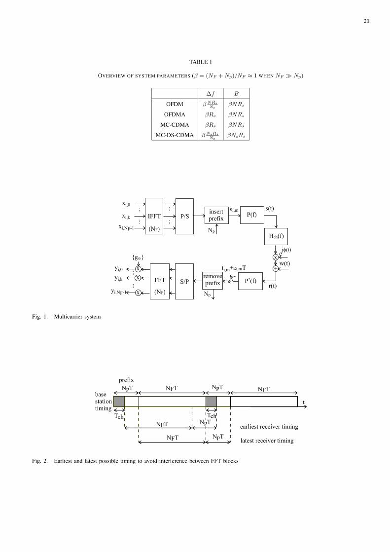
By means of the orthogonal multicarrier system from Fig. 1, we transmit a sequence of vectors {xi}. The
vector xi consists of NF components; the kth component of xi is denoted xi,k. The transmitter computes
the NF -point inverse fast Fourier transform (IFFT) of xi, and then cyclically extends the resulting block
of NF samples with a prefix of Np samples. This yields FFT blocks of NF +Np samples, that are applied
sequentially at a rate 1/T to a square-root raised cosine transmit filter P (f) with rolloff α and unit-energy
impulse response p(t). The mth sample si,m of the ith IFFT block that is applied to the transmit filter is
given by
si,m =1√
NF +Np
NF−1∑
k=0
xi,kej2π km
NF , m = −Np,−Np + 1, . . . , 0, 1, . . . , NF − 1. (1)
Hence, the kth IFFT output gives rise to a baseband signal with carrier frequency k/(NFT ). In order
to avoid aliasing when sampling the received signal at a rate 1/T , the carriers in the rolloff area of the
transmit pulse are not modulated, i.e., they have zero amplitude. Hence, of the NF available carriers, only
Nc ≤ (1 − α)NF carriers are actually modulated. Assuming Nc to be odd, the set of carriers actually
modulated is given by Ic = {0, . . . , (Nc−1)/2}∪{NF − (Nc−1)/2, . . . , NF −1}. Hence, xi,k is nonzero
only for k ∈ Ic, and the summation interval in (1) can be restricted to k ∈ Ic.
5
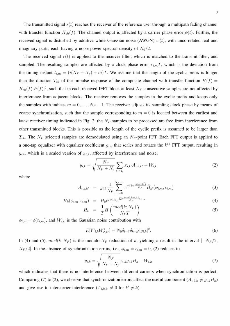
The transmitted signal s(t) reaches the receiver of the reference user through a multipath fading channel
with transfer function Hch(f). The channel output is affected by a carrier phase error φ(t). Further, the
received signal is disturbed by additive white Gaussian noise (AWGN) w(t), with uncorrelated real and
imaginary parts, each having a noise power spectral density of N0/2.
The received signal r(t) is applied to the receiver filter, which is matched to the transmit filter, and
sampled. The resulting samples are affected by a clock phase error εi,mT , which is the deviation from
the timing instant ti,m = (i(NF + Np) + m)T . We assume that the length of the cyclic prefix is longer
than the duration Tch of the impulse response of the composite channel with transfer function H(f) =
Hch(f)|P (f)|2, such that in each received IFFT block at least NF consecutive samples are not affected by
interference from adjacent blocks. The receiver removes the samples in the cyclic prefix and keeps only
the samples with indices m = 0, . . . , NF − 1. The receiver adjusts its sampling clock phase by means of
coarse synchronization, such that the sample corresponding to m = 0 is located between the earliest and
latest receiver timing indicated in Fig. 2: the NF samples to be processed are free from interference from
other transmitted blocks. This is possible as the length of the cyclic prefix is assumed to be larger than
Tch. The NF selected samples are demodulated using an NF -point FFT. Each FFT output is applied to
a one-tap equalizer with equalizer coefficient gi,k that scales and rotates the kth FFT output, resulting in
yi,k, which is a scaled version of xi,k, affected by interference and noise.
yi,k =
√NF
NF +Np
∑
k′∈Icxi,k′Ai,k,k′ +Wi,k (2)
where
Ai,k,k′ = gi,k1
NF
NF−1∑
m=0
e−j2πm(k−k′)
NF Hk′(φi,m, εi,m) (3)
Hk(φi,m, εi,m) = Hkejφi,me
j2πmod(k;NF )
NFεi,m (4)
Hk =1
TH
(mod(k;NF )
NFT
)(5)
φi,m = φ(ti,m), and Wi,k is the Gaussian noise contribution with
E[Wi,kW∗i′,k′ ] = N0δi−i′δk−k′ |gi,k|2. (6)
In (4) and (5), mod(k;NF ) is the modulo-NF reduction of k, yielding a result in the interval [−NF/2,
NF/2]. In the absence of synchronization errors, i.e., φi,m = εi,m = 0, (2) reduces to
yi,k =
√NF
NF +Np
xi,kgi,kHk +Wi,k (7)
which indicates that there is no interference between different carriers when synchronization is perfect.
Comparing (7) to (2), we observe that synchronization errors affect the useful component (Ai,k,k 6= gi,kHk)
and give rise to intercarrier interference (Ai,k,k′ 6= 0 for k′ 6= k).
6
In each of the multicarrier systems to be described below, the data symbols to be transmitted are related
in a specific way to the sequence {xi}, and the equalizer output sequence {yi} is processed in a particular
way to obtain the decision variables, that are applied to the decision device that makes a decision regarding
the transmitted data symbols. The performance of the MC systems is measured by the signal-to-noise ratio
(SNR), which is defined as the ratio of the power of the average useful component (PU ) to the sum of
the powers of the total interference (PI) and the noise (PN ) at the input of the decision device. Note that
for OFDM(A) and MC-DS-CDMA these quantities will depend on the index of the considered carrier,
whereas for MC-CDMA, these quantities are independent of the carrier index.
A. OFDM
The conceptual block diagram of the traditional OFDM system is shown in Fig. 3a. The complex-valued
data symbols to be transmitted at rate Rs are organized into blocks of Nc data symbols; ai,k denotes the
kth data symbol transmitted within the ith block. The index k belongs to a set Ic of Nc carrier indices.
The data symbols ai,k are applied to the IFFT inputs from Fig. 1, i.e., xi,k = ai,k.
The traditional OFDM technique is not a multiple access technique as all carriers are modulated with
data symbols from the same user. To support multiple users, we combine the OFDM technique with the
time-division multiple access (TDMA) scheme. In this case, the time axis is partitioned into a number
of non-overlapping time slots, as shown in Fig. 3b. The time slots are grouped into frames of N time
slots. During each frame, each user is assigned a time slot. Each time slot consists of a burst of NB FFT
blocks, during which Nc data symbols per FFT block can be transmitted in parallel. We denote by ai,k,`
the kth data symbol in the ith block to be transmitted to user `. Note that in OFDM, the number Nc
of carriers can be chosen independently of the number N of users. In OFDM, the sampling rate equals
1/T = (NF +Np)NRs/Nc, and the corresponding carrier spacing ∆f and system bandwidth B are shown
in table I.
In the following, we focus on the detection of the data symbols transmitted to the reference user (` = 0).
The detection of the data symbol ai,k,0 is based upon the decision variable zi,k which equals the equalizer
output corresponding to the kth carrier.
B. OFDMA
The OFDMA system (Fig. 4) is closely related to traditional OFDM. However, in OFDMA, the data
streams that are transmitted on the different carriers belong to different users. Denote by ai,` the ith data
symbol transmitted at a rate Rs to the `th user. The data symbols ai,` belonging to the different users
are transmitted in parallel on the Nc carriers. During one OFDMA block, one data symbol per user is

7
transmitted (see Fig. 4b). This indicates that, as each user is assigned a different carrier, the number Nc
of carriers equals the maximum number N of users. At maximum load, xi,` = ai,`, ` ∈ Ic. The sampling
rate equals 1/T = (NF + Np)Rs. The corresponding carrier spacing ∆f and system bandwidth B are
shown in table I.
The detection of the data symbol ai,0, transmitted to the reference user (` = 0), is based upon zi,0, i.e.
the equalizer output corresponding to the carrier on which the data of the reference user was transmitted.
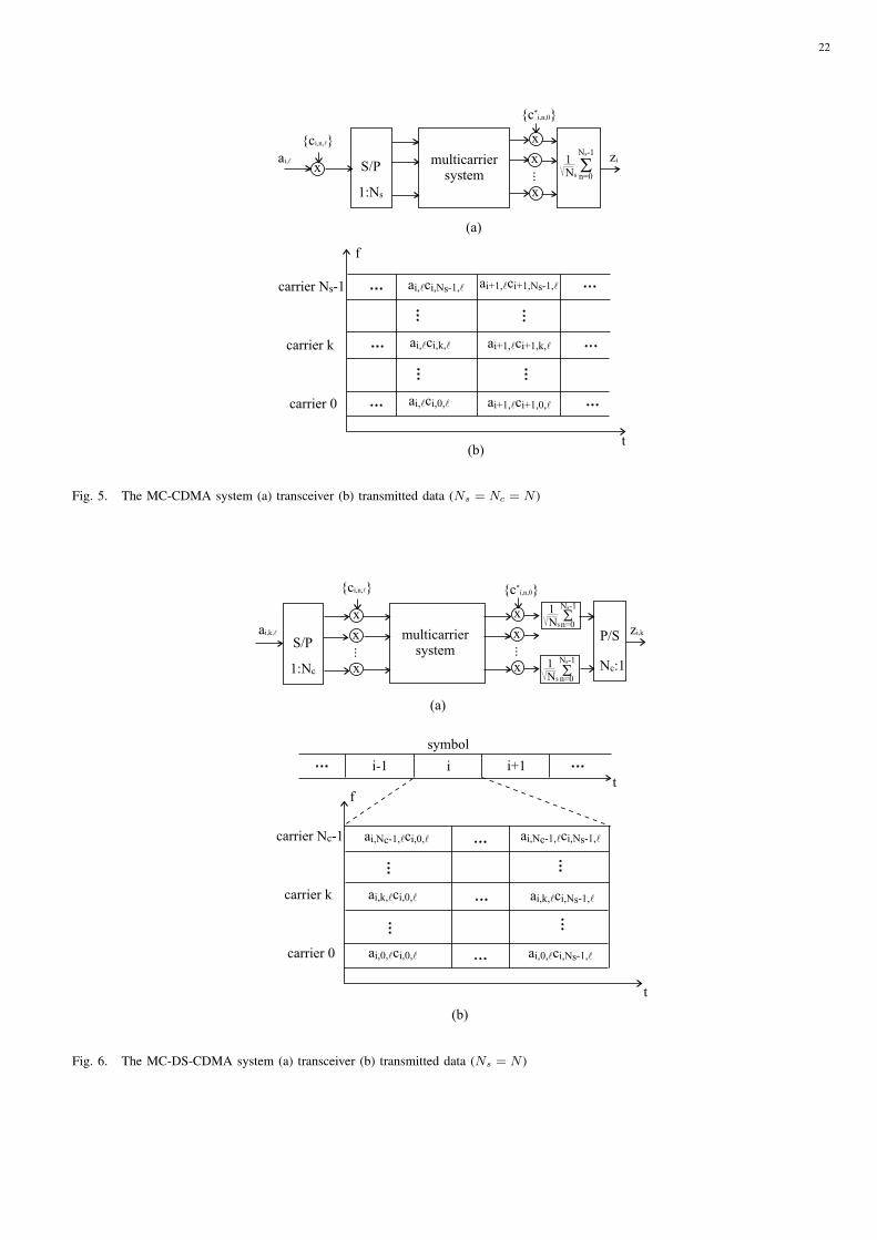
C. MC-CDMA
The conceptual block diagram of the MC-CDMA system is shown in Fig. 5a. The data symbols ai,`
are generated at a rate Rs, where ai,` denotes the ith symbol transmitted to user `. Each data symbol is
multiplied with a spreading sequence {ci,n,`|n = 0, . . . , Ns−1} with a spreading factor Ns, where ci,n,` is
the nth chip of the sequence that spreads the data symbols for user ` during the ith symbol interval. The
Ns components corresponding to the same symbol index i are located in the same time slot on different
carriers, i.e. the spreading is done in the frequency domain (Fig. 5b). Each component has a duration of
1/Rs. The nth chip is mapped on the nth carrier, with n belonging to a set Ic of Nc = Ns carrier indices:
xi,n = ai,`ci,n,`. The sampling rate equals 1/T = (NF +Np)Rs and the corresponding carrier spacing ∆f
and system bandwidth B are shown in table I.
In a multiuser scenario, the basestation broadcasts to all users the sum of the different user signals.
In order that the mobile receiver of the reference user (` = 0) can distinguish between the different user
signals, each user is assigned a unique spreading sequence. In this paper, we assume orthogonal spreading
sequences, which consist of user-dependent Walsh-Hadamard (WH) sequences of length Ns, multiplied
with a complex-valued random scrambling sequence that is common to all users. Hence, the maximum
number of users that can be accommodated equals Ns, i.e. the number of WH sequences of length Ns.
This indicates that the maximum number N of users equals the spreading factor Ns, which in turn equals
the number Nc of modulated carriers.
In MC-CDMA, the equalizer outputs are multiplied with the complex conjugate of the corresponding
chip of the reference user spreading sequence, and summed over the Nc = Ns carriers to obtain the
sample zi, from which a decision is made about the data symbol ai,0.
D. MC-DS-CDMA
The conceptual block diagram of the MC-DS-CDMA system is shown in Fig. 6a. In MC-DS-CDMA,
the complex data symbols to be transmitted at a rate Rs to user ` are split into Nc symbol sequences, each
having a rate Rs/Nc, and each modulating a different carrier of the multicarrier system. We denote by
8
ai,k,` the ith symbol sent on carrier k to user `. The data symbol is multiplied with a spreading sequence
{ci,n,`|n = 0, . . . , Ns − 1} with spreading factor Ns, where ci,n,` denotes the nth chip of the sequence
that spreads the data symbols transmitted to user ` during the ith symbol interval. The Ns components
corresponding to the same symbol index i are located in successive time slots on the same carrier (see
Fig. 6b); each component ai,k,`ci,n,` has a duration of (Nc/Ns)Rs. The inputs of the multicarrier system of
Fig. 1 are xiNc+n,k = ai,k,`ci,n,`. Note that the spreading sequence does not depend on the carrier index k:
all Nc data symbols from user ` that are transmitted during the same symbol interval of duration Nc/Rs
are spread with the same spreading sequence. The sampling rate equals 1/T = (NF + Np)(Ns/Nc)Rs.
The corresponding carrier spacing ∆f and system bandwidth B are shown in table I.
In a multiuser scenario, each user is assigned a different spreading sequence. For MC-DS-CDMA, we
consider the same set of orthogonal spreading sequences as for MC-CDMA. Note that in MC-DS-CDMA,
the number Nc of carriers can be selected independently of the spreading factor Ns, which in turn equals
the maximum number N of users.
Each equalizer output yiNc+n,k is multiplied with the complex conjugate of the corresponding chip ci,n,0
of the spreading sequence of the reference user, and summed over Ns consecutive samples to obtain the
samples zi,k at the input of the decision device.
E. Comparison of System Parameters
Considering that NF � Np, we observe in table I that, when the load is maximum, the bandwidths
occupied by the different MC techniques are the same and equal NRs Hz. Furthermore, it is observed
that, under the same condition, the carrier spacing is the same for OFDM and MC-DS-CDMA (for given
ratio of the number Nc of carriers to the number N of users), and for OFDMA and MC-CDMA.
III. CARRIER SYNCHRONIZATION ERRORS
In this section, we compare the sensitivity of the different MC systems to carrier synchronization errors
in the absence of clock synchronization errors. To clearly isolate the effect of the carrier synchronization
errors, we consider the case of an ideal channel. The case of a dispersive channel will be discussed in
section 5. Further, we assume the maximum load (number of active users equals N ), and the energy per
symbol is equal for all users and all carriers, and is given by Es. In [15]-[17], it is shown that a constant
mismatch between the phases of the carrier oscillator at the transmitter and the receiver can be corrected
by the one-tap equalizers without loss of performance, for any of the multicarrier systems. However, in the
presence of time-varying carrier phase errors, the system performance will be degraded. In the following,
we separately consider the case of a carrier frequency offset and carrier phase jitter.

9
A. Carrier Frequency Offset
A carrier frequency offset ∆F gives rise to φ(t) = 2π∆Ft + φ(0). The effect of a carrier frequency
offset on the MC systems is twofold [14]-[18]. First, a carrier frequency offset introduces a frequency
shift of the downconverted received signal. This results in signal distortion and power loss at the receiver
filter output as a part of the received signal falls outside the bandwidth of the receiver filter. This effect
results in an attenuation of the useful component and the introduction of interference at the receiver
filter output. Secondly, the carrier frequency offset introduces a rotation at a constant speed of 2π∆F
rad/s of the samples at the input of the FFT. This rotation of the FFT input samples gives rise to an
additional reduction of the useful component and additional interference at the FFT outputs. Further, the
FFT outputs are rotating at a constant speed of 2π(NF +Np)∆FT rad/block. The one-tap equalizers are
able to compensate for the systematic rotation of the FFT outputs without loss of performance. However,
the equalizer is not able to correct for the reduction of the useful component without enhancing the noise
power level, nor to eliminate the interference. Hence, the MC systems are degraded in the presence of a
carrier frequency offset. The degradation at the receiver filter output (caused by the frequency shift of the
downconverted signal) is negligibly small as compared to the degradation at the FFT outputs (caused by
the rotation of the receiver filter output samples).
When the carrier frequency offset is larger than the carrier spacing (∆F > ∆f ) of the MC system, the
resulting degradation is very large, as the data transmitted on carrier k are strongly attenuated at the kth
FFT output. In order to keep the degradation within reasonable bounds, we restrict our attention to carrier
frequency offsets smaller than the carrier spacing (∆F < ∆f ). For both OFDM(A) and MC-DS-CDMA,
it can be verified [14]-[15], [17] that the powers of the average useful component, the interference and the
noise (under the assumption of the maximum load and all carriers having the same energy per symbol)
are given by
PUk =NF
NF +Np
Es |DNF (∆FT )|2 (8)
PIk =NF
NF +Np
Es∑
k′∈Ic;k′ 6=k
∣∣∣∣DNF
(k′ − kNF
+ ∆FT
)∣∣∣∣2
(9)
PNk = N0, (10)
where
DNF (x) =1
NF
NF−1∑
m=0
ej2πmx = ejπ(NF−1)x sin(πNFx)
NF sin(πx). (11)
The total interference power (9) depends on the number Nc of modulated carriers, as the summation over
k′ ranges over the set Ic of Nc modulated carriers. A simple upper bound on the interference power is
10
obtained by extending the summation over all NF available carriers, i.e. k′ = 0, . . . , NF − 1. This yields
PIk ≤NF
NF +Np
Es(1− |DNF (∆FT )|2
). (12)
Note that the powers of the useful component (8), the noise (10) and the upper bound on the interference
power (12) are independent of the carrier index k. In the following, we drop the index k.
We approximate the powers of the average useful component and the interference by a truncated Taylor
series, keeping up to quadratic terms, around ∆FT = 0. For |NF∆FT | � 1, this approximation yields
PU ≈ NF
NF +Np
Es (13)
PI ≈NF
NF +Np
Es1
3(πNF∆FT )2 . (14)
From (13) and (14) it follows that the main effect of a carrier frequency offset is the interference, of which
the power quadratically increases with the frequency offset. Further, we observe that the attenuation of
the useful component is negligibly small, when |NF∆FT | � 1. The corresponding degradation of the
signal-to-noise ratio, caused by the presence of the carrier frequency offset is given by
Deg ≈ 10 log
(1 + SNR(0)
1
3(πNF∆FT )2
), (15)
where SNR(0) = (NF/(NF +Np))(Es/N0) is the signal-to-noise ratio in the absence of synchronization
errors.
It can be verified [16] that for MC-CDMA, the powers of the average useful component, the interference
and the noise are obtained by arithmetically averaging of the corresponding powers for OFDM(A) and MC-
DS-CDMA over all modulated carriers k ∈ Ic. As (8), (10) and (12) are independent of the carrier index,
the powers of the average useful component, the interference and the noise in MC-CDMA are the same
as in OFDM(A) and MC-DS-CDMA. Hence the degradation for MC-CDMA can also be approximated
by (15).
The degradation (15) is independent of the carrier index, and depends only on SNR(0) 1 and on
the ratio of the carrier frequency offset to the carrier spacing, i.e. NF∆FT = ∆F/∆f = Nc∆F/B =
(Nc/N)∆F/Rs. Hence, for given ∆F/Rs, the degradation strongly increases with the ratio Nc/N . When
Nc = N , the degradation for all MC systems is the same. Hence, the ratio Nc/N determines which of
the MC systems is more sensitive to a carrier frequency offset: when this ratio is larger (smaller) than 1,
OFDM and MC-DS-CDMA are more (less) sensitive than OFDMA and MC-CDMA (for which Nc = N ).
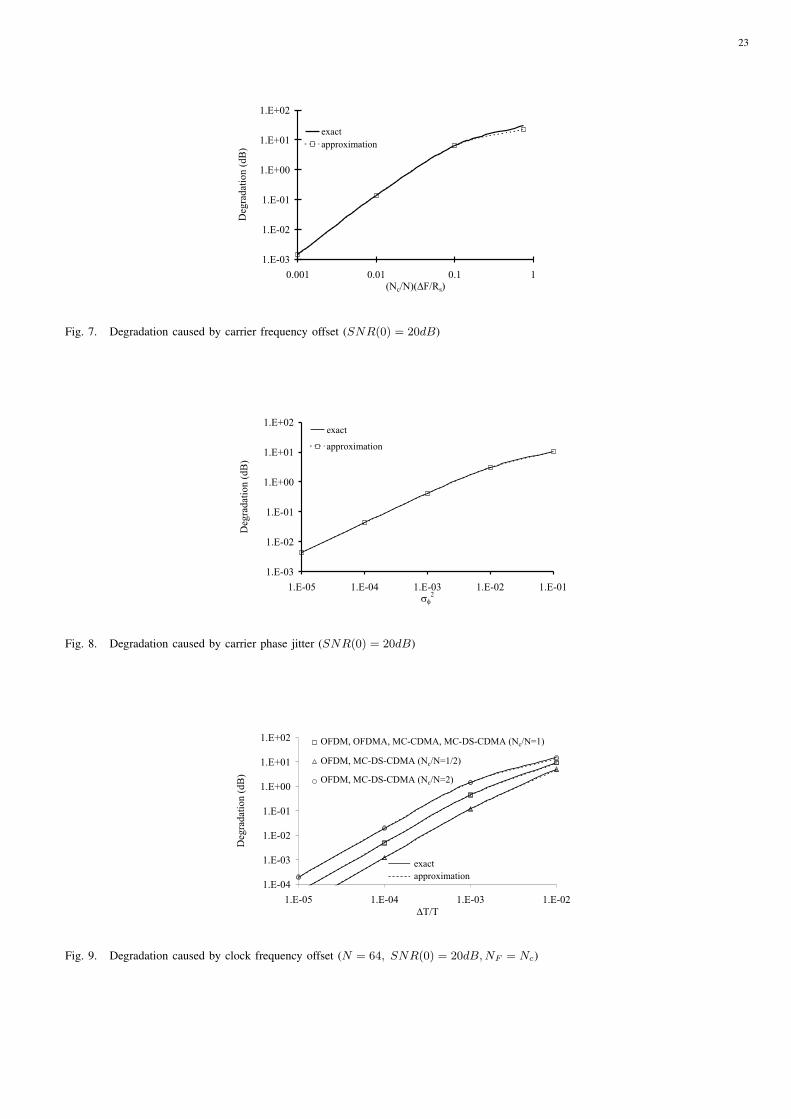
Fig. 7 shows the degradation (15) for the different multicarrier systems as function of (Nc/N)∆F/Rs,
along with the actual degradation. As can be observed, the approximation (15) corresponds well to the
actual degradation when |NF∆FT | � 1. To obtain small degradations, the carrier frequency offset must
1The value of the BER corresponding to SNR(0) depends on the considered (normalized) constellation.

11
be kept small as compared to the carrier spacing, i.e. |∆F/∆f | � 1. In this case, the degradation is
proportional to (NF∆FT )2 = (∆F/∆f)2 = (Nc∆F/B)2 = ((Nc/N)∆F/Rs)2.
B. Carrier Phase Jitter
When the degradation caused by the carrier frequency offset can not be tolerated, the carrier frequency
offset must be corrected in front of the FFT by means of a synchronization algorithm. In this case, the
MC system is affected only by the phase jitter resulting from the synchronizer. The carrier phase jitter
φ(t) is modelled as a zero-mean stationary random process with jitter spectrum Sφ(f) and jitter variance
σ2φ [15]-[16], [19]-[21]. For small jitter variances, i.e. σ2
φ � 1, the phase rotation exp{jφ(t)} at the FFT
outputs can be approximated by the Taylor series: exp{jφ(t)} ≈ 1 + jφ(t). When the load is maximum
and all users and all carriers have the same energy per symbol, it can be verified [15], [19], [21] that
OFDM(A) and MC-DS-CDMA yield the same expression for the power of the average useful component,
the interference and the noise:
PUk =NF
NF +Np
Es (16)
PIk =NF
NF +Np
Es∑
k′∈Ic
∫ +∞
−∞Sφ(f)
∣∣∣∣DNF
(k′ − kNF
+ fT
)∣∣∣∣2
df (17)
PNk = N0. (18)
As the summation over k′ in (17) ranges over the set Ic, the interference power depends on the number
Nc of modulated carriers. By extending the summation interval over all NF available carriers (k′ =
0, . . . , NF − 1), a simple upper bound on the interference power is found:
PIk ≤NF
NF +Np
Esσ2φ, (19)
where the jitter variance is given by
σ2φ =
∫ +∞
−∞Sφ(f)df. (20)
Note that the powers of the average useful component (16), the noise (18) and the upper bound on the
power of the interference (19) are independent of the carrier index. It can be verified [16], [20] that for
MC-CDMA, the powers of the average useful component, the interference and the noise are obtained by
arithmetically averaging the corresponding powers in OFDM(A) or MC-DS-CDMA over all modulated
carriers k ∈ Ic. As these powers in OFDM(A) and MC-DS-CDMA turn out to be independent of the
carrier index, it follows that the sensitivity to carrier phase jitter is the same for all multicarrier systems.
The corresponding degradation is independent of the carrier index, the spectral contents of the jitter, the
spreading factor Ns, the number of carriers Nc and the maximum number N of users, but only depends

12
on the jitter variance:
Deg ≈ 10 log(1 + SNR(0)σ2
φ
), (21)
The performance degradation caused by the carrier phase jitter is shown in Fig. 8. Further, the exact
degradation, assuming the carrier phase jitter is Gaussian distributed, is shown. As we observe, the
degradation (21) yields a good approximation for the actual degradation. For small jitter variances, the
degradation (21) is proportional to σ2φ.
IV. CLOCK SYNCHRONIZATION ERRORS
In this section, we compare the effect of clock synchronization errors on the different multicarrier
systems in the absence of carrier synchronization errors. To clearly isolate the effect of the clock synchro-
nization errors, we consider the case of an ideal channel. The case of a dispersive channel will be discussed
in section 5. Further, the load is taken maximum (number of active users equal to N ), and the energy
per symbol is equal to Es for all carriers and all users. In [15]-[16], it is shown that a constant mismatch
between the phases of the clocks at the transmitter and the receiver does not introduce a performance
degradation, provided that the carriers inside the rolloff area are not modulated, and the cyclic prefix is
sufficiently long. However, in the presence of time-varying timing errors, the performance will degrade.
In the following, we separately consider the case of a clock frequency offset and timing jitter.
A. Clock Frequency Offset
When the receiver of the reference user has a free-running clock with a relative clock frequency offset
∆T/T (∆T/T � 1) as compared to the frequency 1/T of the basestation clock, the timing deviation
linearly increases with time: εi,m = ε0 +(m+i(NF +Np))∆T/T [15]-[16], [22]-[23]. Hence, an increasing
misalignment between the time-domain samples at the transmitter and the receiver is introduced. The
receiver performs a coarse synchronization by selecting the sample m = 0 between the earliest and latest
possible timing, indicated in Fig. 2, such that the NF successive samples kept for further processing
remain in the region where interference from adjacent blocks is absent. After coarse synchronization, the
timing deviation is given by εi,m = εi +m∆T/T , where εi is the timing deviation of the first of the NF
samples of the considered block that are processed by the receiver.
The clock frequency offset gives rise to a reduction of the useful component and to interference at the
FFT outputs. Hence, the MC systems are degraded by a clock frequency offset. When all users and all
carriers exhibit the same energy per symbol, and the load is maximum, it can be verified [15], [22]-[23]
that for OFDM(A) and MC-DS-CDMA the powers of the average useful component, the interference and
13
the noise are given by
PUk =NF
NF +Np
Es
∣∣∣∣DNF
(mod(k;NF )
NF
∆T
T
)∣∣∣∣2
(22)
PIk =NF
NF +Np
Es∑
k′∈Ic;k′ 6=k
∣∣∣∣DNF
(k′ − kNF
+mod(k′;NF )
NF
∆T
T
)∣∣∣∣2
(23)
PNk = N0. (24)
A simple but accurate approximation for the powers of the average useful component (22) and the
interference (23) can be found when |NF∆T/T | � 1 by using truncated Taylor series around ∆T/T = 0,
where only terms up to quadratic are kept:
PUk ≈NF
NF +Np
Es (25)
PIk ≈NF
NF +Np
Es1
3
(πmod(k;NF )
∆T
T
)2
. (26)
From (25) and (26), we observe that the clock frequency offset mainly causes interference; the interference
power turns out to be proportional to the square of the clock frequency offset when |NF∆T/T | � 1.
Further, when |NF∆T/T | � 1, the useful component is essentially not attenuated. The corresponding
degradation yields
Degk ≈ 10 log
(1 + SNR(0)
1
3
(πmod(k;NF )
∆T
T
)2). (27)
The degradation (27) depends on the carrier index and becomes maximum for carriers close to the rolloff
area. We define the average degradation by replacing, in the expression of the SNR, the interference power
by its arithmetical average over the modulated carriers. The corresponding degradation yields [23]
DegAv ≈ 10 log
(1 + SNR(0)
(π
6NF
∆T
T
)2). (28)
In MC-CDMA, the powers of the average useful component, the interference and the noise are ob-
tained by arithmetically averaging the corresponding powers of OFDM(A) and MC-DS-CDMA, over all
modulated carriers k ∈ Ic [16]. The resulting powers can be approximated by truncated Taylor series
around ∆T/T = 0, similar as in OFDM(A) and MC-DS-CDMA. The corresponding degradation equals
the average degradation (28) of OFDM(A) and MC-DS-CDMA.
For all multicarrier systems, the degradation strongly increases with NF∆T/T . Hence, for given ∆T/T ,
the degradation rapidly increases when the number Nc (. NF ) of modulated carriers increases. The
(average) degradation, caused by a clock frequency offset is shown in Fig. 9, along with the actual (average)
degradation. As can be observed, the approximation (28) corresponds well to the actual degradation when
|NF∆T/T | � 1. For Nc = N , all MC systems exhibit the same degradation. For the systems where
14
the number of carriers can be chosen independently of the number of users (i.e. OFDM and MC-DS-
CDMA), the average degradation is larger or smaller than for OFDMA and MC-CDMA, depending on
whether Nc > N or Nc < N , i.e. when the number of carriers is larger or smaller than the number of
users. To obtain small degradations, it is required that |NF∆T/T | � 1, in which case the degradation is
proportional to (NF∆T/T )2.
B. Timing Jitter
To avoid the degradation associated with a clock frequency offset, we can perform synchronized
sampling at the output of the receiver filter. When a timing synchronization algorithm is used to adjust the
sampling clock, the MC systems are affected only by the timing jitter resulting from the synchronizer. The
timing jitter εi,mT is modelled as a zero-mean stationary random process with jitter spectrum Sε(ej2πfT )
and jitter variance σ2ε [15]-[16], [24]-[25]. When the jitter variance is small, i.e. σ2
ε � 1, the phase
rotation exp(j2πmod(k;NF )/NF εi,m) at the FFT outputs can be approximated by a truncated Taylor
series: exp(j2πmod(k;NF )/NF εi,m) ≈ 1 + j2πmod(k;NF )/NF εi,m.
In OFDM(A) and MC-DS-CDMA ([15], [25]), the powers of the average useful component, the
interference and the noise turn out to be the same, when the load is maximum and all users and all
carriers have the same energy per symbol:
PUk =NF
NF +Np
Es (29)
PIk =NF
NF +Np
Es∑
k′∈Ic
(2πmod(k′;NF )
NF
)2
·
∫ + 12T
− 12T
Sφ(ej2πfT )
∣∣∣∣DNF
(k′ − kNF
+ fT
)∣∣∣∣2
df (30)
PNk = N0. (31)
The total interference power depends on the carrier index k and becomes maximum for carriers close
to the rolloff area. We define the average degradation, by replacing in the expression of the SNR, the
powers of the average useful component, the interference and the noise by their arithmetical average over
all modulated carriers. The average degradation still depends on the number of modulated carriers, as the
summation over the carrier indices k and k′ ranges over the set Ic of Nc modulated carriers. A simple
upper bound on the average degradation is found by extending the summations over all NF available
carriers, i.e. k, k′ = 0, . . . , NF − 1. The corresponding degradation yields
DegAv ≤ 10 log
(1 + SNR(0)
π2
3σ2ε
), (32)

15
where the jitter variance is given by
σ2ε =
∫ + 12T
− 12T
Sε(ej2πfT )df. (33)
This average degradation is independent of the spectral contents of the jitter, the spreading factor, the
number of carriers and the number of users, but only depends on the jitter variance.
In MC-CDMA, the powers of the average useful component, interference and noise are obtained by
arithmetically averaging the corresponding powers of OFDM(A) and MC-DS-CDMA over all modulated
carriers k ∈ Ic [16]. Hence, the degradation of MC-CDMA is the same as the average degradation of
OFDM(A) and MC-DS-CDMA, and can be upper bounded by (32).
The (average) degradation (32) caused by timing jitter is shown in Fig. 10. Further, the exact average
degradation, assuming the timing jitter is Gaussian distributed, is shown. As we observe, the degradation
(32) yields a good approximation for the actual degradation. For small jitter variances, the degradation is
proportional to σ2ε .
V. CONCLUSIONS AND REMARKS
In this paper, we have presented simple but accurate analytical expressions for the degradations caused
by different types of synchronization errors, and compared the sensitivity of several multicarrier systems
to these synchronization errors. For the maximum load, an ideal channel and the energy per symbol equal
for all carriers and all users, the results can be summarized as follows.
• The degradation caused by a carrier frequency offset is proportional to ((Nc/N)∆F/Rs)2, with
∆F/Rs denoting the ratio of the carrier frequency offset to the symbol rate. The degradation is
independent of the carrier index. For given ∆F/Rs, the degradation depends on the ratio Nc/N ;
when the ratio Nc/N is larger (smaller) than 1, OFDM and MC-DS-CDMA yield a larger (smaller)
degradation than OFDMA and MC-CDMA (where Nc = N ).
• The MC systems are very sensitive to a clock frequency offset. The degradations of OFDM(A) and
MC-DS-CDMA depend on the carrier index, and are proportional to (NF∆T/T )2. When Nc/N = 1,
the average degradation of OFDM(A) and MC-DS-CDMA is the same as the degradation of MC-
CDMA. This degradation strongly increases with NF∆T/T , and does not depend on the spreading
factor. For given ∆T/T , the sensitivity depends on the ratio Nc/N . For Nc/N larger (smaller) than
1, OFDM and MC-DS-CDMA are more (less) sensitive than OFDMA and MC-CDMA. To obtain a
small degradation, it is required that |NF∆T/T | � 1.
• All MC systems exhibit the same sensitivity to carrier phase jitter. The degradation is independent of
the carrier index, the spreading factor, the number of carriers, the number of users and the spectral
contents of the jitter. The degradation only depends on the jitter variance.

16
• Timing jitter causes a degradation that depends on the carrier index for OFDM(A) and MC-DS-
CDMA. The average (over all FFT outputs) degradation of OFDM(A) and MC-DS-CDMA is equal
to the degradation for MC-CDMA. This degradation is independent of the spreading factor, the
number of carriers, the number of users and the spectral contents of the jitter, but only depends on
the jitter variance.
In this paper, we separately considered the effect of the different synchronization errors. For small
synchronization errors, i.e. for which the approximations obtained in this paper are valid, it can be verified
that the degradation, caused by two or more types of synchronization errors, can be approximated by the
sum of the degradations caused by the different synchronization errors separately.
In this paper, we have restricted our attention to the effect of synchronization errors in the downlink,
assuming an ideal channel. This analysis can be extended for the uplink and/or slowly varying multipath
fading channels (wide-sense stationary uncorrelated scattering (WSSUS) multipath fading channel).
• In the considered OFDM system, the signals of the different users do not interfere as they are
physically separated in time. As a result, the analysis for the uplink system reduces, similar as in
the downlink, to the analysis of a single user system. Hence, assuming an ideal channel, the effect
of the synchronization errors on uplink OFDM is the same as in the downlink [26].
• When all users exhibit the same jitter spectra, it can be verified [19], [21], [25]-[26] that the
degradation caused by carrier phase jitter or timing jitter for OFDMA and MC-DS-CDMA, for
an ideal channel, is the same in the uplink and the downlink.
• In uplink OFDMA and MC-DS-CDMA, the contributions of all users are affected by a different
carrier or clock frequency offset. As a result, there is a larger amount of interference from the other
users as compared to the downlink, where the carrier or clock frequency offset are the same for all
users. Hence, assuming an ideal channel, the degradation caused by carrier or clock frequency offset
in uplink OFDMA and MC-DS-CDMA is larger than in the downlink [17], [23], [26].
• It can be shown that for both uplink and downlink OFDM(A) and MC-DS-CDMA, assuming perfect
power control, the degradations in the presence of a slowly varying multipath fading channel, caused
by synchronization errors, are the same as in the case of an ideal channel [17], [23], [26].
• In downlink MC-CDMA, similar expressions for the degradation caused by the different types of
synchronization errors can be obtained in the presence of a slowly varying multipath fading channel
[26].
• In uplink MC-CDMA, the different user signals are not aligned in time, and are sent over different
multipath fading channels. This causes significant interference between the user signals that cannot
be compensated by one-tap equalizers, even in the absence of synchronization errors. To combat the

17
interference in uplink MC-CDMA, a much more complicated receiver structure is needed. Hence, the
simple analytical expressions obtained in this paper cannot easily be extended to the case of uplink
MC-CDMA.

18
REFERENCES
[1] J.A.C. Bingham. 1990. Multicarrier Modulation for Data Transmission: An Idea Whose Time Has Come. IEEE Comm. Mag. 1990;
28(5):5-14.
[2] P.S. Chow, J.C. Tu, J.M. Cioffi. 1991. Performance Evaluation of a Multichannel Transceiver System for ADSL and VHDSL. IEEE J.
on Select. Areas in Comm. 1991; 9(8):909-919.
[3] H. Sari, G. Karam, I. Jeanclaude. 1995. Transmission Techniques for Digital Terrestrial TV Broadcasting. IEEE Comm. Mag. 1995;
33(2):100-109.
[4] G. Santella. 1995. Bit Error Rate Performances of M-QAM Orthogonal Multicarrier Modulation in Presence of Time-Selective Multipath
Fading. in Proceedings ICC’95 Seattle, WA:1683-1688.
[5] IEEE 802.11. 1997. IEEE standard for Wireless LAN Medium Access Control (MAC) and Physical Layer (PHY) Specifications.
[6] ETSI. 1996. Radio Equipment and Systems, HIgh PErformance Radio Local Area Network (HIPERLAN) Type 1. European
Telecommunications Standard, ETS 300-652
[7] H. Sari, Y. Levy and G. Karam. 1996. Orthogonal Frequency-Division Multiple Access for the Return Channel on CATV Networks.
in Proceedings International Conference on Telecommunications ICT’96, Istanbul:602-607.
[8] S. Hara, R. Prasad. 1997. Overview of Multicarrier CDMA. IEEE Communications Magazine 1997; 35(12):126-133.
[9] K. Fazel, L. Papke. 1993. On the Performance of Convolutionally Sequenced CDMA/OFDM for Mobile Communication System. in
Proceedings IEEE PIMRC’93, Yokohama, Japan:468-472.
[10] N. Yee, J-P. Linnartz, G. Fettweis. 1993. Multicarrier CDMA in Wireless Radio Networks, in Proceedings IEEE PIMRC’93, Yokohama,
Japan:109-113.
[11] A. Chouly, A. Brajal, S. Jourdan. 1993. Orthogonal Multicarrier Techniques Applied to Direct Sequence Spread Spectrum CDMA
techniques. in Proceedings IEEE Globecom’93, Houston, USA:1723-1728.
[12] V.M. DaSilva, E.S. Sousa. 1993. Performance of Orthogonal CDMA Sequences for Quasi-Synchronous Communication Systems. in
Proceedings IEEE ICUPC’93, Ottawa, Canada:995-999.
[13] S. Kondo, L.B. Milstein. 1996. Performance of Multicarrier DS-CDMA Systems. IEEE Transactions on Communications 1996;
44(2):238-246.
[14] T. Pollet, M. Moeneclaey. 1996. The Effect of Carrier Frequency Offset on the Performance of Band-Limited Single Carrier and OFDM
Signals. in Proceedings Globecom 96, London:719-723.
[15] H. Steendam, M. Moeneclaey. 2000. Sensitivity of Orthogonal Frequency-Division Multiplexed Systems to Carrier and Clock
Synchronisation Errors. Signal Processing 2000; 80(7):1217-1229.
[16] H. Steendam, M. Moeneclaey. 1999. The Sensitivity of MC-CDMA to Synchronisation Errors. European Trans. on Telecomm. ETT
special issue on MC-SS; 10(4):429-436.
[17] H. Steendam, M. Moeneclaey. 2001. The Effect of Carrier Frequency Offsets on Downlink and Uplink MC-DS-CDMA. IEEE Journal
on Sel. Areas in Communications 2001; 19(12):2528-2536.
[18] L. Tomba and W.A. Krzymien. 1996. Effect of Carrier Phase Noise and Frequency Offset on the Performance of Multicarrier CDMA
Systems. in Proceedings ICC 1996, Dallas TX:1513-1517.
[19] H. Steendam, M. Moeneclaey, H. Sari. 1998. The Effect of Carrier Phase Jitter on the Performance of Orthogonal Frequency-Division
Multiple Access Systems. IEEE Trans. on Comm. 1998; 46(4):456-459.
[20] H. Steendam, M. Moeneclaey. 1999. The Effect of Carrier Phase Jitter on MC-CDMA. IEEE Trans. on Comm. 1999; 47(2):195-198.
[21] H. Steendam, M. Moeneclaey. 2001. The Effect of Carrier Phase Jitter on MC-DS-CDMA. in Proceedings ICC’01, Helsinki,
Finland:1881-1884.
[22] T. Pollet, M. Moeneclaey. 1995. Synchronizability of OFDM Signals. in Proceedings Globecom 95, Singapore:2054-2058.
[23] H. Steendam, M. Moeneclaey. 2004. A Comparison between Uplink and Downlink MC-DS-CDMA Sensitivity to Static Clock Phase
and Frequency Offsets. submitted to IEEE Transactions on Wireless Communications.
19
[24] L. Tomba and W.A. Krzymien. 1998. A Model for the Analysis of Timing Jitter in OFDM Systems. in Proceedings ICC 1998, Atlanta
GA:1227-1231.
[25] H. Steendam, M. Moeneclaey. 2004. The Effect of Timing Jitter on MC-DS-CDMA. to appear in IEEE Transactions on Communications;
52(3).
[26] H. Steendam. The Effect of Synchronization Systems on Multicarrier Systems. PhD thesis, 2000. http://telin.UGent.be/ hs/full/PHD.zip.
20
TABLE I
OVERVIEW OF SYSTEM PARAMETERS (β = (NF +Np)/NF ≈ 1 WHEN NF � Np)
∆f B
OFDM βNRsNc
βNRs
OFDMA βRs βNRs
MC-CDMA βRs βNRs
MC-DS-CDMA βNsRsNc
βNsRs
Fig. 1. Multicarrier system
Fig. 2. Earliest and latest possible timing to avoid interference between FFT blocks

21
Fig. 3. The OFDM system (a) transceiver (b) transmitted data
Fig. 4. The OFDMA system (a) transceiver (b) transmitted data (Nc = N )
22
Fig. 5. The MC-CDMA system (a) transceiver (b) transmitted data (Ns = Nc = N )
Fig. 6. The MC-DS-CDMA system (a) transceiver (b) transmitted data (Ns = N )
23
Fig. 7. Degradation caused by carrier frequency offset (SNR(0) = 20dB)
Fig. 8. Degradation caused by carrier phase jitter (SNR(0) = 20dB)
Fig. 9. Degradation caused by clock frequency offset (N = 64, SNR(0) = 20dB,NF = Nc)
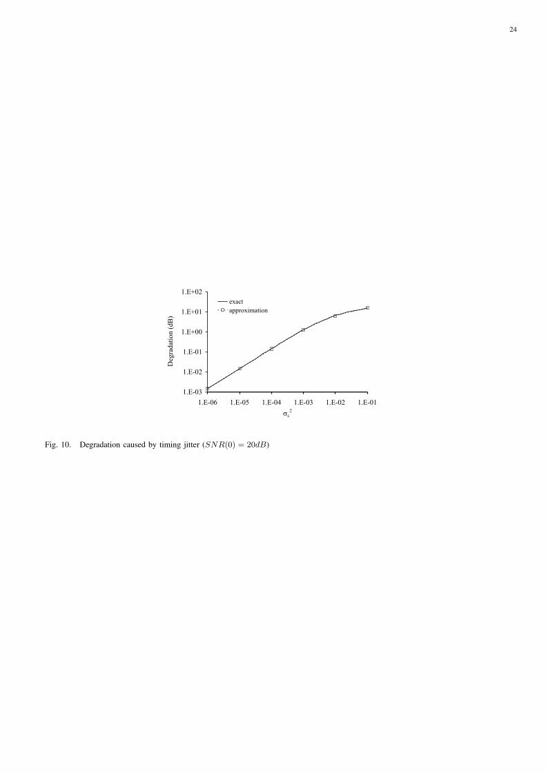
24
Fig. 10. Degradation caused by timing jitter (SNR(0) = 20dB)