constellation design for a multicarrier optical wireless
TRANSCRIPT

214 IEEE TRANSACTIONS ON COMMUNICATIONS, VOL. 62, NO. 1, JANUARY 2014
Constellation Design for a MulticarrierOptical Wireless Communication Channel
Qian Gao, Member, IEEE, Jonathan H. Manton, Senior Member, IEEE,Gang Chen, Member, IEEE, and Yingbo Hua, Fellow, IEEE
Abstract—A block-wise constellation design is presented foroptical communication systems with multi-subcarrier modulation(MSM), intensity modulation (IM) and direct detection (DD). TheDC-bias traditionally used only for compensating the negativepeaks of the transmitter-side signals is treated as an information-carrying basis in our proposed scheme called MSM-JDCM.Designs are done for both flat-fading and frequency selective-fading scenarios, and following a principle of high dimensionalsphere packing. To simplify the problem, we apply the followingmethods. First, we use bounds on the waveform’s maximumand minimum. Second, we use the maximum and minimumconstraints on a set of sufficient samples of waveforms. Third,we relax non-convex distance constraints into convex ones byiterative linearizations. With the MSM-JDCM, we minimizeelectrical power, optical power, and peak power with a commontarget bit error rate (BER). Analysis shows that the MSM-JDCM offers significant power gains over MSM-Normal andMSM-SPSS. The short-term peak to average power ratio (PAPR)and long-term PAPR constraints are combined with the MSM-JDCM to mitigate the nonlinear distortion caused by high poweramplifier and laser diode, which is another novelty of our scheme.To attain lower BER, a binary switching algorithm (BSA) isapplied to find the improved constellation labeling.
Index Terms—Optical wireless communication, constellationdesign, multicarrier optical, IM/DD, frequency-selective opticalchannels, peak to average power ratio, constellation label-ing/mapping.
I. INTRODUCTION
IN recent decades, there has been an increasing level ofinterests in optical wireless communications, including
infrared, visible light, and ultraviolet communications [1]–[4].Optical wireless communications offer a potential of high-speed transmissions in unregulated bands. Analogous to themulticarrier modulation employed in the RF systems [5],multiple-subcarrier modulation (MSM) has been proposed forthe optical systems [6]–[9], where a transmitter modulatesmultiple electrical subcarriers onto the optical carrier throughintensity modulation (IM), and a receiver captures the intensitymodulated signals by a way of direct detection (DD). This isa non-coherent system and much cheaper to implement thanits counterparts known as the all-optical systems [10].
Manuscript received March 1, 2013; revised August 20 and November 5,2013. The editor coordinating the review of this paper and approving it forpublication was E. Agrell.
Q. Gao, G. Chen, and Y. Hua are with the Department of ElectricalEngineering, University of California, Riverside, CA 92521, USA (e-mail:{qgao, gachen, yhua}@ee.ucr.edu).
J. H. Manton is with the Department of Electrical and ElectronicEngineering, The University of Melbourne, Parkville, Australia (e-mail:[email protected]).
Digital Object Identifier 10.1109/TCOMM.2013.112213.130166
MSM along with IM/DD is a widely considered schemefor use in scattering environments [11]–[13]. For flat-fadingenvironment, MSM is known to yield a higher spectral effi-ciency than traditional binary modulation techniques such ason-off keying (OOK) and pulse position modulation (PPM)[14, Chapter 5]. However, to our knowledge, MSM has beenused only for flat-fading channels.
Constellation design is important for MSM IM/DD systems[15]–[17]. A good constellation design should be power effi-cient, including electrical, optical and peak-power efficiencies.A stream-wise scheme termed MSM-Normal is proposed in[15], and a block-wise one termed MSM-SSPS (subcarriersignal point sequence) is in [16] and [17]. With the MSM-Normal, bit sequences are independently modulated ontoindividual subcarriers using BPSK/QPSK (binary phase shiftkeying and quadrature phase shift keying). But the sum of thesubcarrier waveforms likely contains a large negative peakwhich needs to be compensated by a DC (direct current)power, which compromises the power efficiency. With theMSM-SSPS, a more general constellation for multiple subcar-riers with both I and Q channels is designed, which requiresa less DC power for negative peak compensation. However,none of these two schemes treats the DC-bias as part ofthe information basis. In [18], a sphere packing problem isformulated for constellation design of a single-carrier system,which treats the DC-bias as an information carrying basis.
In this paper, we will consider the constellation designfor the MSM IM/DD system with either flat fading orfrequency-selective fading channels. We propose a joint DCand multicarrier constellation design scheme, termed MSM-JDCM. This scheme provides an optimized constellation ina connected region in high dimensional space with the DC-bias as an information basis. Convex optimization problemsare formulated in Section III and solved by CVX [20] toprovide optimized constellations. A good constellation designshould not only be power efficient but also robust to the HPAand/or LD’s nonlinearities. To deal with these nonlinearities,traditional schemes include selective mapping [21], partialtransmit sequence [22], clipping [23], tone reservation [24],vector precoding [25], companding transform [26], and others[27]. In this paper, we show that our constellation designscheme MSM-JDCM, along with short-term PAPR (peak toaverage power ratio) or long-term PAPR constraints, providesa robustness against the nonlinearities. Near the end of the pa-per, we also consider a labeling problem (i.e., bits-to-symbolsmapping) after a constellation is given. In the literature, the
0090-6778/14$31.00 c© 2014 IEEE

GAO et al.: CONSTELLATION DESIGN FOR A MULTICARRIER OPTICAL WIRELESS COMMUNICATION CHANNEL 215
labeling schemes include the Gray Code mapping [28], set-partitioning mapping [29], [30], maximum squared Euclideanweight mapping [31], the binary switching algorithm (BSA)[32]. Among them, the BSA is able to accommodate labelingin a high dimensional space, and our simulation results showthat the labeling using BSA noticeably reduces the BER (biterror rate) for a fixed SER (symbol error rate). A brief versionof this paper is available in [19].
Throughout the paper, we will use the following conven-tions. Boldface upper-case letters denote matrices, boldfacelower-case letters denote column vectors, and standard lower-case letters denote scalars. (·)T and (·)−1 denote the transposeand inverse operators. ∗ denotes convolution. E denotes theexpectation operator. < · > and || · || denote the Euclideaninner product and Euclidean norm. ⊗ denotes the Kroneckerproduct. Rn denotes the n-dimensional real space. The set ofall integers is denoted by Z. By ei, we denote a vector withall zeros but the value one at the i-th element. By I, we denotethe identity matrix. By O, we denote an all zero matrix. And∇(·) denotes the gradient operator.
II. MSM IM/DD OPTICAL COMMUNICATION SYSTEMS
A. The Flat-fading Channel Model
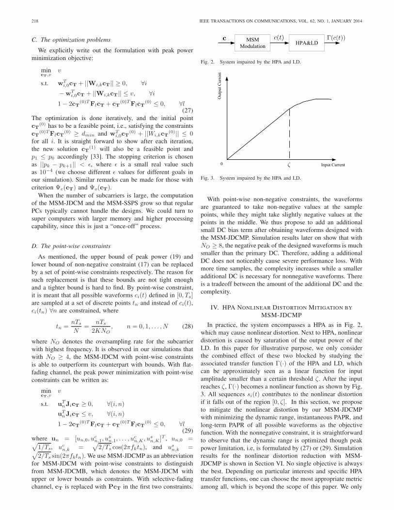
Fig. 1 shows the system block diagram of an IM/DD opticalwireless network. The received signal y(t) can be written as[2]
y(t) = γηs(t) ∗ h(t) + v(t) (1)
where t is continuous time index, s(t) denotes the intensitysignal sent by the laser diode (LD), y(t) the received pho-tocurrent by the photodetector (PD), h(t) the channel impulseresponse, η the electro-optical conversion factor in watts perampere (W/A), and γ the photodetector responsivity. Signalintensity has to be non-negative, i.e.,
s(t) ≥ 0 (2)
which is the fundamental constraint differentiating IM/DDfrom many coherent modulated systems and an important basisof the schemes mentioned later in this article.
The proposed methods for constellation design and label-ing require the channel state information which is typicallystatic and easy to obtain for practical indoor optical wirelesscommunications. We consider flat-fading channel model first.With a constant channel h = 1 assumed for multiple symbolintervals, the model is simplified to
r(t) = γηs(t) + n(t) (3)
where γη = 1 can be further assumed without loss ofgenerality. In our design, s(t) is chosen from a signal setS = {s1(t), s2(t), . . . , sNc(t)}, where each signal in the setis to be designed and Nc is the constellation size. The discretevector channel model can be written as:
r[p] = s[p] + n[p] p ∈ [1, Nc] (4)
where we assume the noise vector n[p] has independentrandom Gaussian elements with zero mean and variance N0/2per dimension. We refer the readers to [18] for details aboutthe relationship between the discrete and continuous channel
LaserDiode
JDCM Modulation
Matched Filter
JDCMDemodulation
Fig. 1. The system block diagram with the MSM-JDCM.
models. It should be noted that [p] is to index the “discrete”signal space and (tn) will be used to index the “discrete” timesamples of the continuous signal waveforms.
Power metrics are thus defined: 1. the average electricalpower Ψe(t) = 1
TsEi[s2i (t)] (the average is taken over i);
2. the average optical power Ψo(t) = η√TsEi[si(t)], 3. the
peak optical power Ψpo(t) = ηmaxi,t si(t). The index i isuniformly taking value from set I = {1, 2, . . . , Nc} and Ts
is the symbol interval. The peak electrical power Ψpe(t) isoptimal as long as Ψpo(t) is optimized [18] so that it is omittedhere. Other metrics such as the PAPR and dynamic range areanalyzed in Section IV.
B. The information basis
Our transmission scheme is illustrated in Fig. 1. Denoteφ(t) = [φ1(t), φ2(t), . . . , φM (t)]T as a sequence of orthonor-mal information basis modulated by ci, the i-th symbolvector. φ1(t) is associated with the DC-bias, which is aswell used by MSM-Normal and MSM-SSPS, but only forbiasing purpose (not an information basis and is dropped bythe receiver). The transmitted signal si(t) by the LD is givenby si(t) = ηφT (t)ci.
If both I and Q channels are used by each subcarrier forMSM-JDCM, we term it MSM-JDCM-IQ, thus M = 2K+1.If only the I channels are used, we term it MSM-JDCM-I,thus M = K + 1. The information basis is typically chosenas follows.
φ1(t) =
√1
TsΠ(
t
Ts) (5)
φ2k(t) =
√2
Tscos(2πfkt)Π(
t
Ts) k = 1, 2, . . . ,K (6)
φ2k+1(t) =
√2
Tssin(2πfkt)Π(
t
Ts) k = 1, 2, . . . ,K
(7)where
Π(t) =
{1, if 0 ≤ t < 10, otherwise.
(8)
where fk = kTs
is the frequency of k-th subcarrier. The rect-angular window defined in (8) is not a practical signal to usein a real-world IM/DD channel due to its infinite bandwidthrequirement, thus in this paper we propose to employ a “time-domain raised cosine (TDRC)” window defined as follows
Π(t) =
⎧⎪⎨⎪⎩0.5
(1 + cos[πβ (t− β)]
)if 0 < t < β,
1 if β ≤ t ≤ 1− β,
0.5(1 + cos[πβ (t− 1 + β)]
)if 1− β < t ≤ 1.
(9)

216 IEEE TRANSACTIONS ON COMMUNICATIONS, VOL. 62, NO. 1, JANUARY 2014
We will choose a small β in this paper.
C. The waveform distances
The basis waveforms are typically normalized, i.e., thefollowing holds
< φn(t), φm(t) >=
{1 m = n,0 otherwise.
(10)
Straightforwardly, the inner product and Euclidean distancerelationships between two waveforms hold as follows
< ci(t), cj(t) >=< ci, cj > (11)
||ci(t)− cj(t))|| = ||ci − cj || (12)
The detection performance at the receiver, especially at highsignal-to-noise ratio (SNR), is governed by the minimumdistance among all waveform pairs.
D. The bit-to-symbol mapping
For the MSM-JDCM and MSM-SPSS, the bit sequence bi
is mapped onto a symbol vector ci jointly, i.e.,
ci = f(bi) (13)
where bi ∈ {b1,b2, . . . ,bNc} ∈ RNb , ci ∈{c1, c2, . . . , cNc} ∈ RM , and Nc = 2Nb . f(·) is called the“block-wise (BLW)” mapping function.
For the MSM-Normal, “subcarrier-wise (SCW)” mappingis employed, which maps bits onto subcarriers individually,i.e.
(cI,k, cQ,k) = f(bI,k, bQ,k) k = 1, . . . ,K (14)
where I and Q stand for real and imaginary part respectively.(cI,k, cQ,k) can take values from only (±a,±a). The summa-tion of all subcarriers pulses is then biased. The designing ofthe mapping functions is referred to as “constellation labeling”problem.
E. MSM-JDCM vs MSM-SSPS
The advantage of the MSM-JDCM over the MSM-SSPS isthreefold: 1. the dimension of information basis of the MSM-JDCM is always higher than the MSM-SSPS by one, which isdue to the use of DC-bias as information basis; 2. the MSM-JDCM searches constellation points in a continuous space,while MSM-SSPS restricts the searching space to a “discretelattice” of size 9K . Each subcarrier picks symbols from a(8+1)-APSK constellation [17]; 3. MSM-SPSS has to use bothI and Q channels for each subcarrier.
F. The selective-fading channel model
While multiple non-line-of-sight optical links exist, wechoose the geometric series model for analysis in the paper,i.e.,
h′(t) = γ∑i
βiδ(t− τi) (15)
where δ(·) is a dirac-delta function, 0 < βi < 1 and τi �Ts are real numbers denoting the gain and delay of the i-thchannel tap respectively. γ is a very small value denoting the
common path-loss which can be lumped into noise variance,and therefore we only consider the simplified channel
h(t) =∑i
βiδ(t− τi) (16)
There are other choices for modeling the selective-fadingchannel, e.g., the exponential decay model, ceiling bouncemodel, and etc.. Comparisons among different channel modelscan be found in [36]. With the chosen h(t), we propose todesign a set of pre-equalizers before ci comes into the JDCMmodulator.
Proposition 1. The pre-equalizers that mitigate the effectof frequency-selective channel (16) are linear, and have thefollowing form:
Pk =1
|zk|2[
Re(zk) −Im(zk)Im(zk) Re(zk)
], for k-th subcarrier
po =1∑i βi
, for DC-bias
where zk =∑
i βie−k2πfkτi . Thus the modulating vector ci =
Pci, where the symbol vector ci is pre-equalized by the block-diagonal matrix P = bdiag{p0,P1, . . . ,PK}.
The proof can be found in Appendix B.
III. THE OPTIMIZATION PROBLEM
A. The objective functions
The MSM-JDCM is targeted at optimizing the joint symbolvector cT = [cT1 , c
T2 , . . . , c
TNc
]T ∈ R(2K+1)Nc (for the IQchannels case). When the optimization goal is to minimizethe average electrical power, the objective function is givenby
Ψe(cT) =1
NcTs
Nc∑i=1
||ci||2 =1
NcTscT
T cT (17)
where i is uniformly distributed over I. While for minimizingthe optical average power, the objective function is written as
Ψo(cT) =η
Nc
√Ts
Nc∑i=1
ci,1 =η
Nc
√Ts
Nc∑i=1
jT(i−1)M+1cT
(18)where j(i−1)M+1 = [0, . . . , 1, . . . , 0]T is a (2K + 1)Nc × 1column vector with all zeros at except the (i − 1)M + 1’selement, and therefore only the DC-bias part of each candidatewaveform is averaged. The exact form of optical peak powerconstraint is hard to get and we aim at the upper bound of itas in the following. For a an arbitrary packet, the optical peak

GAO et al.: CONSTELLATION DESIGN FOR A MULTICARRIER OPTICAL WIRELESS COMMUNICATION CHANNEL 217
power is
Ψpo(cT) = ηmaxt,i
ci(t− jTs) = ηmaxt,i
ci(t)
≤ η√Ts
maxi
{K∑
k=1
√2(c2i,2k + c2i,2k+1) + ci,1}
=η√Ts
maxi
{K∑
k=1
||Akci||+ aT0 ci}
=η√Ts
maxi
{K∑
k=1
||AkJicT||+ aT0 JicT}
=η√Ts
maxi
{K∑
k=1
||Wi,kcT||+wTi,0cT} (19)
Ψpe(cT) =Ψ2
po(cT)
η2(20)
(19) can be straightforwardly derived to upper boundthe peak power, and we later show in III-D that thisbound can be replaced by a set of point-wise con-straints. By introducing the following notations: Ak =√2 diag(0, . . . , 0, 1, 1, 0, . . . , 0) with the 2k-th and 2k + 1-th
elements as 1’s, a0 = [1, 0, . . . , 0]T of dimension (2K+1)×1,Ji = [O2K+1, . . . , I2K+1,O2K+1, . . . ,O2K+1] of dimension2K + 1 × Nc(2K + 1), Wi,k � AkJi, and wT
i,0 � −aT0 Ji.The optical peak power Ψpo(c) and electrical peak Ψpe(c)power has a relationship of (20) such that optimizing oneautomatically guarantees the optimality of the other.
Besides the performance metrics mentioned above, one canchoose to use linear combination of a number of objectives, orby running the optimization solver multiple times with moreand more severe constraints. In other words, because thereare competing performance metrics, there could be a rangeof different answers depending on which metrics are moreimportant. This is important in practice and one can formulatedifferent problems with combining or modifying the problemswe address in this paper.
B. The constraints
With IQ channels, The symbol vector ci ∈ R2K+1 can takevalues from a connected region as long as the nonnegativeconstraint is satisfied as follows.
mint
ci(t) = mini,t
φ(t)T ci = mint
2K+1∑m=1
ci,mφm(t) ≥ 0 (21)
With derivations in the equation at the bottom of the page,a sufficient but not necessary set of constraints can be used
to guarantee the nonnegativeness of the transmitted signals asfollows
Gi(cT) � ci,1 −K∑
k=1
√2(c2i,2k + c2i,2k+1)
= wTi,0cT +
K∑k=1
||Wi,kcT|| ≥ 0 ∀i (22)
These are convex constraints in cT. Later we show in III-Dthat a set of point-wise constraints serves as a replacement ofthis bound, with very little computational redundancy.
Besides the non-negativeness of signal, constraint has tobe put also on the minimum distance among all constellationpoint pairs.
hl(cT) � cTTFlcT ≥ dmin, l = 1, 2, . . .
(Nc − 1)Nc
2(23)
where Fl(p,q) = Epq , Ep = eTp ⊗ INc , ep has a dimension of(2K + 1)× 1, and Epq = ET
p Ep −ETp Eq −ET
q Ep +ETq Eq.
The following relation holds.
l(p, q) = (p−1)Nc−p(p+ 1)
2+q, p, q ∈ 1, 2, . . . , Nc, p < q
(24)For short, replace l(p, q) with l. dmin = 1 is assumedthroughout this paper without loss of generality.
The distance constraints are nonconvex in cT and we firstlyapproximate the exteriors of the ellipses (high order cylinders)hl(c) < 1 with the first order Taylor series at cT(0), i.e.
hl(cT) ∼= H(0)l (cT)
= hl(cT(0)) +∇hT (cT
(0))(cT − cT(0))
= cT(0)TFlcT
(0) + 2cT(0)TFl(cT − cT
(0))
= 2cT(0)TFlcT − cT
(0)TFlcT(0) ≥ 1, ∀l (25)
This approximation restricts the feasible region into a halfspace defined by H
(0)l (cT) ≥ 1. By running the algorithm
with the above approximation once a new point cT(1) is
found, which is guaranteed to maintain 1 ≤ cT(1)TFlcT
(1) ≤cT
(0)TFlcT(0) [33]. Then using Taylor series again at cT(1),
the feasible region is now approximated by a new halfspaceH
(1)l (cT) ≥ 1, which has H
(0)l (cT) ≥ 1 as a subspace.
We call this process as the “iterative Taylor series approxi-mation”, which iteratively finds the supporting hyperplane ofhl(cT) < 1 as the feasible region containing a local optimum.With multiple runs at a set of wide spread initial points, weexpect to find the global optimum.
For simplicity, we drop the iteration index and write theminimum distance constraint as:
1−Hl(cT) ≤ 0, ∀l (26)
mint
ci(t) = mint
[√1Tsci,1Π(
tTs) +
√2Ts
(∑Kk=1 ci,2k cos(2πfkt) +
∑Kk=1 ci,2k+1 sin(2πfkt)
)Π( t
Ts)
]
=√
1Ts
mint
[ci,1 +
∑Kk=1
√2(c2i,2k + c2i,2k+1) cos(2πfkt− θk)
]t ∈ [0, Ts]
≥√
1Ts
mint
[ci,1 −
∑Kk=1
√2(c2i,2k + c2i,2k+1)
]t ∈ [0, Ts]
218 IEEE TRANSACTIONS ON COMMUNICATIONS, VOL. 62, NO. 1, JANUARY 2014
C. The optimization problems
We explicitly write out the formulation with peak powerminimization objective:
mincT,v
v
s.t. wTi,0cT + ||Wi,kcT|| ≥ 0, ∀i
−wTi,0cT + ||Wi,kcT|| ≤ v, ∀i
1− 2cT(0)TFlcT + cT
(0)TFlcT(0) ≤ 0, ∀l
(27)The optimization is done iteratively, and the initial pointcT
(0) has to be a feasible point, i.e., satisfying the constraintscT
(0)TFlcT(0) ≥ dmin and wT
i,0cT(0) + ||Wi,kcT
(0)|| ≤ 0for all i. It is straight forward to show after each iteration,the new solution cT
(1) will also be a feasible point andp1 ≤ p0 accordingly [33]. The stopping criterion is chosenas ||pk − pk+1|| < ε, where ε is a small real value suchas 10−4 (we choose different ε values for different goals inour simulation). Similar remarks can be made for those withcriterion Ψe(cT) and Ψo(cT).
When the number of subcarriers is large, the computationof the MSM-JDCM and the MSM-SSPS grow so that regularPCs typically cannot handle the designs. We could turn tosuper computers with larger memory and higher processingcapability, since this is just a “once-off” process.
D. The point-wise constraints
As mentioned, the upper bound of peak power (19) andlower bound of non-negative constraint (17) can be replacedby a set of point-wise constraints respectively. The reason forsuch replacement is that these bounds are not tight enoughand a tighter bound is hard to find. By point-wise constraint,it is meant that all possible waveforms ci(t) defined in [0, Ts]are sampled at a set of discrete points tn and instead of ci(t),ci(tn) ∀n are constrained, where
tn =nTs
N=
nTs
2KNO, n = 0, 1, . . . , N (28)
where NO denotes the oversampling rate for the subcarrierwith highest frequency. It is observed in our simulations thatwith NO ≥ 4, the MSM-JDCM with point-wise constraintsis able to outperform its counterpart with bounds. With flat-fading channel, the peak power minimization with point-wiseconstraints can be written as:
mincT,v
v
s.t. uTnJicT ≥ 0, ∀(i, n)
uTnJicT ≤ v, ∀(i, n)
1− 2cT(0)TFlcT + cT
(0)TFlcT(0) ≤ 0, ∀l
(29)where un = [un,0, u
cn,1, u
sn,1, . . . , u
cn,K , us
n,K ]T , un,0 =√1/Ts, uc
n,k =√2/Ts cos(2πfktn), and us
n,k =√2/Ts sin(2πfktn). We use MSM-JDCMP as an abbreviation
for MSM-JDCM with point-wise constraints to distinguishfrom MSM-JDCMB, which denotes the MSM-JDCM withupper or lower bounds as constraints. With selective-fadingchannel, cT is replaced with PcT in the first two constraints.
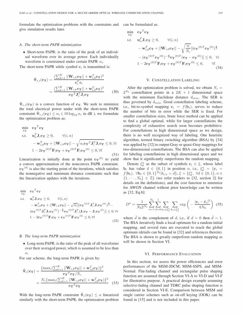
MSMModulation HPA&LD
Fig. 2. System impaired by the HPA and LD.
Input Current
Out
put C
urre
nt
0
Fig. 3. System impaired by the HPA and LD.
With point-wise non-negative constraints, the waveformsare guaranteed to take non-negative values at the samplepoints, while they might take slightly negative values at thepoints in the middle. We thus propose to add an additionalsmall DC bias term after obtaining waveforms designed withthe MSM-JDCMP. Simulation results later on show that withNO ≥ 8, the negative peak of the designed waveforms is muchsmaller than the primary DC. Therefore, adding a additionalDC does not noticeably cause severe performance loss. Withmore time samples, the complexity increases while a smalleradditional DC is necessary for nonnegative waveforms. Thereis a tradeoff between the amount of the additional DC and thecomplexity.
IV. HPA NONLINEAR DISTORTION MITIGATION BY
MSM-JDCMP
In practice, the system encompasses a HPA as in Fig. 2,which may cause nonlinear distortion. Next to HPA, nonlineardistortion is caused by saturation of the output power of theLD. In this paper for illustrative purpose, we only considerthe combined effect of these two blocked by studying theassociated transfer function Γ(·) of the HPA and LD, whichcan be approximately seen as a linear function for inputamplitude smaller than a certain threshold ζ. After the inputreaches ζ, Γ(·) becomes a nonlinear function as shown by Fig.3. All sequences si(t) contributes to the nonlinear distortionif it falls out of the region [0, ζ]. In this section, we proposeto mitigate the nonlinear distortion by our MSM-JDCMPwith minimizing the dynamic range, instantaneous PAPR, andlong-term PAPR of all possible waveforms as the objectivefunction. With the nonnegative constraint, it is straightforwardto observe that the dynamic range is optimized though peakpower limitation, i.e, is formulated by (27) or (29). Simulationresults for the nonlinear distortion reduction with MSM-JDCMP is shown in Section VI. No single objective is alwaysthe best. Depending on particular interests and specific HPAtransfer functions, one can choose the most appropriate metricamong all, which is beyond the scope of this paper. We only
GAO et al.: CONSTELLATION DESIGN FOR A MULTICARRIER OPTICAL WIRELESS COMMUNICATION CHANNEL 219
formulate the optimization problems with the constraints andgive simulation results later.
A. The short-term PAPR minimization
• Short-term PAPR: is the ratio of the peak of an individ-ual waveform over its average power. Each individuallywaveform is constrained under certain PAPR αi.
The short-term PAPR while symbol ci is transmitted is:
Ψe,i(cT) =(∑K
k=1 ||Wi,kcT||+wTi,0cT)
2
cTi ci
=(∑K
k=1 ||Wi,kcT||+wTi,0cT)
2
cTTJTi JicT
(30)
Ψe,i(cT) is a convex function of cT. We seek to minimizethe total electrical power under with the short-term PAPRconstraint Ψe,i(cT) ≤ αi ( 10 log10 αi in dB ), we formulatethe optimization problem as:
mincT
cTT cT
s.t. uTnJicT ≥ 0, ∀(i, n)−wT
i,0cT + ||Wi,kcT|| −√αicTTJT
i JicT ≤ 0, ∀i1− 2cT
(0)TFlcT + cT(0)TFlcT
(0) ≤ 0, ∀l(31)
Linearization is initially done at the point cT(0) to yield
a convex approximation of the nonconvex PAPR constraint.cT
(0) is also the starting point of the iterations, which satisfiesthe nonnegative and minimum distance constraints such thatthe linearization updates with the iterations.
mincT
cTT cT
s.t. uTnJicT ≥ 0, ∀(i, n)−wT
i,0cT + ||Wi,kcT|| − √αi[(cT
(0)TJTi JicT
(0))12−
(cT(0)TJT
i JicT(0))−
12 cT
(0)TJTi (JicT − JicT
(0))] ≤ 0,∀i1− 2cT
(0)TFlcT + cT(0)TFlcT
(0) ≤ 0, ∀l(32)
B. The long-term PAPR minimization
• Long-term PAPR: is the ratio of the peak of all waveformsover their averaged power, which is assumed to be less thanα.
For our scheme, the long-term PAPR is given by:
Ψe(cT) ={maxi(
∑Kk=1 ||Wi,kcT||+wT
i,0cT)}2cTT cT/Nc
=Nc{maxi(
∑Kk=1 ||Wi,kcT||+wT
i,0cT)}2cTT cT
(33)
With the long-term PAPR constraint Ψe(cT) ≤ α linearizedsimilarly with the short-term PAPR, the optimization problem
can be formulated as:
mincT
cTT cT
s.t. uTnJicT ≥ 0, ∀(i, n)−wT
i,0cT + ||Wi,kcT|| −√
α
Nc[(cT
(0)T cT(0))
12
− (cT(0)T cT
(0))−12 cT
(0)T (cT − cT(0))] ≤ 0, ∀i
1− 2cT(0)TFlcT + cT
(0)TFlcT(0) ≤ 0, ∀l
(34)
V. CONSTELLATION LABELING
After the optimization problem is solved, we obtain Nc =2Nb constellation points in a 2K + 1 dimensional spacewith the minimum Euclidean distance dmin. The SER isthus governed by dmin. Good constellation labeling scheme,i.e., bit-to-symbol mapping ci = f(bi), serves to reducethe number of bits in error while the SER is fixed. Forsmaller constellation sizes, brute force method can be appliedto find a global optimal, while for larger constellations thecomplexity of exhaustive search soon becomes prohibitive.For constellations in high dimensional space as we design,there is no well recognized way of labeling. One heuristicalgorithm, termed binary switching algorithm (BSA) by [34]was applied by [32] to output Gray or quasi-Gray mappings fortwo-dimensional constellations. The BSA can also be appliedfor labeling constellations in high dimensional space and weshow that it significantly outperforms the random mapping.
Denote ξnd as the subset of symbols ci ∈ ξ, whose labelbi has value d ∈ {0, 1} in position n, i.e., ξnd = {ci =f(bi), ∀bi ∈ {0, 1}Nb|bi,n = d}, ξ = {ξnd , ∀d ∈ {0, 1}, n ∈{1, · · · , Nb} ∈ Z} (we refer readers to [32, section 2] fordetails on the definitions), and the cost function to minimizefor AWGN channel without prior knowledge can be writtenas [32, Eq.6]:
Da =1
Nb2Nb
Nb∑n=1
1∑d=0
∑ci∈ξnd
∑ci∈ξn
d
exp
(− |ci − ci|2
4N0
)(35)
where d is the complement of d, i.e., if d = 0 then d = 1.The BSA iteratively finds a local optimum for a random initialmapping, and several runs are executed to reach the globaloptimum (details can be found in [32] and references therein).The BSA is shown to greatly outperform random mapping aswill be shown in Section VI.
VI. PERFORMANCE EVALUATION
In this section, we assess the power efficiencies and errorperformances of the MSM-JDCM, MSM-SSPS, and MSM-Normal. Flat-fading channel and rectangular pulse shapingfunction are assumed through Section VI-A to VI-D and VI-Ffor illustrative purpose. A practical design example assumingselective-fading channel and TDRC pulse shaping function isconsidered in Section VI-E. Comparison between MSM andsingle carrier schemes such as on-off keying (OOK) can befound in [15] and is not included in this paper.

220 IEEE TRANSACTIONS ON COMMUNICATIONS, VOL. 62, NO. 1, JANUARY 2014
TABLE ITHE POWER GAINS WITH MEDIUM-TO-HIGH SNR.
����g01,22E,16 g01,22O,16 g01,22P,16 g02,22E,16 g02,22O,16 g02,22P,16 g03,22E,16 g03,22O,16 g03,22P,16
Nb = 4 (IQ) 0.97 1.08 0.93 3.15 2.28 2.64 4.55 3.36 3.88
Nb = 4 (I) 0.58 0.67 0.42����
��������
6.27 4.11 3.78
����g01,33E,64 g01,33O,64 g01,33P,64 g02,33E,64 g02,33O,64 g02,33P,64 g03,33E,64 g03,33O,64 g03,33P,64
Nb = 6 (IQ) 1.90 1.73 1.06 4.54 2.79 5.98 6.20 4.23 5.54
Nb = 6 (I) 1.42 1.21 0.85����
��������
7.57 4.70 4.52
A. SER and BER
For the MSM-JDCM and MSM-SPSS, we assume that eachsymbol is transmitted with equal probability. The union boundof SER is derived as [18, Eq.25]
Es,1 ≈ 2Nn
NcQ
(√d2min,1
2N0
)� p1Q
(√d2min,1
2N0
)(36)
where Q(x) = 1√2π
∫∞x
exp(−t2/2)dt is the Gaussian Q-function, dmin,1 is the minimum Euclidean distance, and Nn
is the number of neighbor pairs (which is defined in SectionVI-F). The corresponding BER is
Eb,1 =λ1
NbEs,1 =
λ1
Nbp1Q
(√d2min,1
2N0
)(37)
where λ1 denotes the average number of bits in error whenone symbol is in error (we seek to minimize λ1 by the BSAin section VI-F).
For the MSM-Normal, we regard that one symbol is in errorif any subcarrier is not correctly detected. The SER can thenbe derived as
Es,2 = p2
[1−
(1−Q
(√d2min,2
2N0
))K]
≈ p2KQ
(√d2min,2
2N0
)� p2Q
(√d2min,2
2N0
)(38)
where 0 < p2 < 1 and p2 < p1 typically. The approximateequation is valid for medium-to-high SNR case, where theQ-function dominate the SER. The corresponding BER is
Eb,2 = λ2p2Q
(√d2min,2
2N0
), for small N0 (39)
where λ2 is the average number of bits in error when onesymbol is in error.
B. The symbol waveforms and power gains
For the MSM-JDCMP, define the constellations optimizedfor electrical power, optical power, and peak power with sizeNc and K subcarriers as Θ0,K
E,Nc, Θ0,K
O,Nc, and Θ0,K
P,Nc. For
the MSM-JDCMB, define the corresponding constellationsas Θ1,K
E,Nc, Θ1,K
O,Nc, and Θ1,K
P,Nc. The coordinates of selected
optimized constellations are given in Appendix A. Though theMSM-SSPS in [17] is design specifically for reducing the dc-bias, we generalize it to accommodate the electrical power, op-tical power, and peak power reduction and the corresponding
0 0.2 0.4 0.6 0.8 10
0.5
1
1.5
2
2.5
3
3.5
t
Am
plitu
de
Fig. 4. MSM-normal symbol waveforms with adaptive bias.
0 0.2 0.4 0.6 0.8 10
0.5
1
1.5
2
2.5
3
3.5
4
t
Am
plitu
de
Fig. 5. MSM-normal symbol waveforms with enough bias.
optimized constellations with size Nc are denoted as Θ2,KE,Nc
,Θ2,K
O,Nc, and Θ2,K
P,Nc. For the MSM-Normal, no optimization
is associated. Θ3,KNc
stands for the corresponding constellationwith adaptive bias and Θ4,K
Ncfor enough-biased1. We assume
Ts = 1 without loss of generality. The oversampling rateNO = 8 without severely adding to computational cost.300 random initializations are chosen in order to obtain thebest constellation. Due to space limit, only the correspondingwaveforms with Nb = 4 for the three schemes are shown forillustrative purpose.
We compare the power efficiencies of the three schemeswhen the same target SER and the same spectrum efficiency
1Enough-biased means the DC bias added to each unbiased waveformequals the absolute value of the largest negative peak of all signal waveforms.

GAO et al.: CONSTELLATION DESIGN FOR A MULTICARRIER OPTICAL WIRELESS COMMUNICATION CHANNEL 221
0 0.2 0.4 0.6 0.8 10
0.5
1
1.5
2
2.5
3
3.5
4
t
Am
plitu
de
Fig. 6. MSM-SSPS symbol waveforms minimizing the electrical power.
0 0.2 0.4 0.6 0.8 10
0.5
1
1.5
2
2.5
3
3.5
4
t
Am
plitu
de
Fig. 7. MSM-SPSS symbol waveforms minimizing the optical power.
0 0.2 0.4 0.6 0.8 10
0.5
1
1.5
2
2.5
3
t
Am
plitu
de
Fig. 8. MSM-JDCMP symbol waveforms minimizing the electrical power.
(bit/s/Hz) are achieved. The power gains are defined as
gxy,kxky
Z,Nc= 10 log10
Py,ky
Z,Nc
P x,kx
Z,Nc
[dB] (40)
where Nc is the constellation size, Z ∈ {E,O, P}, x, y ∈{0, 1, 2, 3, 4}, kx and ky are the number of subcarriers schemex and y use respectively. Since the Q-function part dominatethe SERs with medium-to-high SNR, we can neglect themultiplicative factor p1 and p2 in this case with only negligibleover-estimation of the power gains2, as in Table I at the bottomof this page.
Fig. 4−Fig. 10 include the designed symbol waveformsaccordingly for the MSM-Normal, MSM-SPSS, and MSM-JDCMP with Nb = 4 and K = 2. Different waveforms
2In other words, with medium-to-high SNR, we only need to slightlyincrease dmin,1 to obtain a large decrease of SER without significantlyincrease the overall power.
0 0.2 0.4 0.6 0.8 10
0.5
1
1.5
2
2.5
3
3.5
4
t
Am
plitu
de
Fig. 9. MSM-JDCMP symbol waveforms minimizing the optical power.
0 0.2 0.4 0.6 0.8 10
0.5
1
1.5
2
2.5
tA
mpl
itude
Fig. 10. MSM-JDCMP symbol waveforms minimizing the peak power (K =2, Nb = 4).
5 10 15 20 2510
−7
10−6
10−5
10−4
10−3
10−2
10−1
100
SNR
SE
R
MSM−JDCMPMSM−SPSSMSM−Normal
Fig. 11. SER performance of the three schemes when K = 2, Nb = 4,with the same Ea.
are associated with different colors. We observe that thewaveforms associated with the MSM-Normal and MSM-SPSSare less “irregular” while the one with MSM-JDCMP seemsmore random. Intuitively, the MSM-JDCMP is expected totake better usage of the design space. The Monte-Carlosimulation comparing the symbol error rate performance of thethree schemes is shown by Fig. 11, where the testing symbolsequence is of length 2× 10⁶.
C. Spectral efficiency and Power efficiency tradeoff
Increasing K for a fixed Nb, i.e., sacrificing a portion ofthe spectrum efficiency, could serve to increase the powerefficiency. Θ0,4
E,16 offers 2.31dB electrical power gain overΘ0,2
E,16. Corresponding waveforms are shown in Fig. 12. Itshould be noted that no further gain is guaranteed to beachieved with further increasing K, e.g. Θ0,6
E,16 is no better

222 IEEE TRANSACTIONS ON COMMUNICATIONS, VOL. 62, NO. 1, JANUARY 2014
0 0.2 0.4 0.6 0.8 10
0.5
1
1.5
2
2.5
3
t
Am
plitu
de
Fig. 12. MSM-JDCMP symbol waveforms minimizing the electrical power(K = 4, Nb = 4).
0 0.2 0.4 0.6 0.8 10
0.5
1
1.5
2
2.5
3
3.5
4
t
Am
plitu
de
Fig. 13. MSM-JDCMP symbol waveforms with short-term PAPR ≤ 3dB.
than Θ0,4E,16.
D. Nonlinear distortion mitigation with the MSM-JDCMP
Fig. 13 shows the waveforms designed to constraint theshort-term PAPR to be 3dB with K = 2 and Nb = 4 bychoosing αi = α ∀i. Fig. 14 shows the waveforms designedto constraint the long-term PAPR to be 3dB. Whether onecriterion is better than the others depends on the exact formof the transfer function of HPA and the probabilities of symboloccurrence. If a certain sequence has a nontrivially higherchance of transmission, it is better to force its amplitude intothe linear region and in the mean time control the dynamicrange of all sequences.
E. Selective-fading channel with TDRC pulse shaper: a designexample
We consider a chosen selective-fading channel
h(t) =1
2δ(t)+
1
4δ(t− 1
18)+
1
10δ(t− 1
9)+
1
20δ(t− 1
6) (41)
And we use the window function as defined in (9) as pulseshaper, with the roll-off factor β = 0.1. When K = 2 andNb = 4, we can obtain the pre-equalizer by using Proposition1 calculated as follows
P =
⎡⎢⎢⎢⎢⎣1.1111 0 0 0 0
0 1.1350 0.2620 0 00 −0.2620 1.1350 0 00 0 0 1.2230 0.54090 0 0 −0.5409 1.2230
⎤⎥⎥⎥⎥⎦(42)
With MSM-JDCMP, the designed waveforms are shown byFig. 15.
0 0.2 0.4 0.6 0.8 10
0.5
1
1.5
2
2.5
3
3.5
t
Am
plitu
de
Fig. 14. MSM-JDCMP symbol waveforms with long-term PAPR ≤ 3dB.
0 0.2 0.4 0.6 0.8 10
0.5
1
1.5
2
2.5
3
3.5
4
4.5
tA
mpl
itude
Fig. 15. MSM-JDCMP symbol waveforms minimizing the electrical powerwith selective-fading channel (K = 2, Nb = 4).
F. The improved labelings
Recall the BER in (37)
Pb =2λ1Nn
NbNcQ
(√1
2N0
)(43)
where the erroneous number of bits λ needs to be minimized.In the previous sections we only calculated the Q functionpart, while this assumption is only accurate with medium tohigh SNRs. The constant multiplicative part should also betaken into account with lower SNR.
Two points are treated as neighbors if the following holds
1 ≤ ||ci − cj || ≤ 1 + δ (44)
where δ is chosen such that
Q(√Ea/2N0)
Q(√(1 + δ)2Ea/2N0)
≥ μ (45)
SNR = 10 log10Ea
N0[dB] (46)
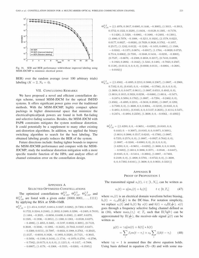
where SNR stands for the signal-to-noise ratio, Ea is theaverage electrical energy over all waveforms, μ is a largenumber so that only pairs with distances smaller than 1 + δare treated as neighbors, i.e., The pairwise error associatedwith non-neighbor pairs is neglected. μ = 100 is chosen inthis section. It can be observed by simulations that furtherincreasing μ does not change the results much. For Θ0,2
E,16,the best corresponding constellation labeling is found for eachSNR value by BSA. The exhaustive search method, if applied,needs to compare 64! different labeling such that it is toocostly to be useful. It can be observed from Fig. 16 thatimproved labeling offers a marginal BER gain (0.1dB at 10−6
GAO et al.: CONSTELLATION DESIGN FOR A MULTICARRIER OPTICAL WIRELESS COMMUNICATION CHANNEL 223
0 2 4 6 8 10 12 14 16 18 20 2210
−7
10−6
10−5
10−4
10−3
10−2
10−1
100
SNR
SE
R/B
ER
SERBER (Improved labeling)BER (Random labeling)
Fig. 16. SER and BER performance with/without improved labeling usingMSM-JDCMP to minimize electrical power.
BER) over the random average (over 100 arbitrary trials)labeling (K = 2, Nb = 4).
VII. CONCLUDING REMARKS
We have proposed a novel and efficient constellation de-sign scheme, termed MSM-JDCM for the optical IM/DDsystems. It offers significant power gains over the traditionalmethods. With the MSM-JDCMP, highly compact spherepackings in higher dimensional space that minimize theelectrical/optical/peak powers are found in both flat-fadingand selective-fading scenarios. Besides, the MSM-JDCM withPAPR constraints mitigates the system nonlinear distortion.It could potentially be a supplement to many other existinganti-distortion algorithms. In addition, we applied the binaryswitching algorithm to search for the best labeling. Theobtained labeling greatly reduces the BER of the system.
Future directions include: finding tighter bounds to improvethe MSM-JDCMB performance and compare with the MSM-JDCMP; study the nonlinear distortion mitigation with a morespecific transfer function of the HPA; and analyze effect ofchannel estimation error on the constellation design.
APPENDIX ASELECTED OPTIMIZED CONSTELLATIONS
The optimized constellations Θ0,2E,16, Θ0,2
P,16, Θ1,2E,16, and
Θ1,2P,16 are listed with a given order (0000, 0001, . . . , 1111)
by applying the BSA at SNR=10dB.
Θ0,2E,16 = {(1.4514, 0.0527, 0.6814, 0.3327, 0.0282), (0.7202, 0.5695,
0.1722, 0.3244, 0.2160), (1.2032, 0.2489, 0.3290,−0.2405, 0.7819),
(1.1484,−0.2025,−0.0656, 0.6490, 0.4580), (1.4097, 0.6370,
0.1505,−0.1936,−0.2851), (1.1380, 0.1383,−0.0538, 0.6275,
− 0.4886), (1.4055, 0.3465,−0.5197, 0.0022, 0.3691), (0.7123,
0.3648,−0.5046,−0.1093,−0.3425), (0.7042, 0.0167, 0.6471,
− 0.3300, 0.0151), (0.7097,−0.6024, 0.1988, 0.2763,−0.2043),
(1.4127,−0.6016, 0.1626,−0.1893, 0.3320), (0.7121,−0.3645,
− 0.5056,−0.1100, 0.3416), (1.1716,−0.1970, 0.2791,−0.2796,
− 0.7582), (0.0173, 0, 0, 0, 0), (1.1215, 0,−0.1417,−0.7808,
− 0.0007), (1.4179,−0.3368,−0.5555,−0.0263,−0.3595)}
Θ0,2P,16 = {(1.4976, 0.3817, 0.6085, 0.1446,−0.3005), (1.5015,−0.3913,
0.5752, 0.1322, 0.3329), (1.0434,−0.0129, 0.1305,−0.7170,
− 0.1426), (1.5320,−0.6861,−0.1680,−0.2493,−0.1301),
(1.4980, 0.7078,−0.1088,−0.3211, 0.1024), (2.1578, 0.0221,
0.0177, 0.0027,−0.0026), (0.7029, 0.3826, 0.5762,−0.1057,
0.2517), (1.1242, 0.0122,−0.1249,−0.1455, 0.6901), (1.1508,
− 0.0242,−0.1371, 0.0674,−0.6917), (1.1764,−0.0020, 0.0725,
0.7514, 0.0062), (0.7595,−0.5048, 0.5416,−0.0235,−0.3083),
(0.7537,−0.6670,−0.2388, 0.2658, 0.2217), (0.7410, 0.6899,
− 0.1923, 0.2692,−0.1642), (1.5241, 0.1483,−0.7023, 0.2567,
0.1128), (0.0112, 0, 0, 0, 0), (0.6930, 0.0131,−0.6804,−0.2681,
− 0.0102)}
Θ1,2E,16 = {(1.6562,−0.4895, 0.2213, 0.5880, 0.2367), (1.0887,−0.2969,
0.7102, 0, 0), (0.8165, 0, 0,−0.0286,−0.5766), (0, 0, 0, 0, 0),
(1.3608, 0, 0, 0.0477, 0.9611), (1.0887, 0.6551, 0.4043, 0, 0),
(1.6614, 0.1615, 0.5024, 0.0238,−0.6466), (1.6614,−0.5471,
− 0.2474, 0.5094, 0.1762), (1.0887,−0.7294,−0.2462, 0, 0),
(1.6562,−0.4895, 0.2213,−0.5616, 0.2938), (1.0887, 0.1292,
− 0.7589, 0, 0), (1.3608, 0, 0, 0.8084,−0.5219), (0.8165, 0, 0,
− 0.4851, 0.3131), (0.8165, 0, 0, 0.5137, 0.2635), (1.6114, 0.5471,
− 0.2474,−0.4894, 0.2258), (1.3608, 0, 0,−0.8562,−0.4392)}
Θ1,2P,16 = {(1.6293, 0, 0,−0.9651,−0.6292), (0.8165, 0, 0,
0.4443, 0.− 0.3687), (0.8165, 0, 0, 0.0971, 0.5691),
(1.6614, 0.3886, 0.3517, 0.6243,−0.1700), (1.0887,
0.7255, 0.2574, 0, 0), (1.0887,−0.0927, 0.7642, 0, 0),
(1.0887,−0.3240,−0.6983, 0, 0), (0, 0, 0, 0, 0),
(1.6293, 0, 0,−0.9651,−0.6292), (1.3608, 0, 0, 0.1639,
− 0.9482), (1.6614, 0.3886, 0.3571,−0.0548,−0.6447),
(0.8165, 0, 0,−0.5414,−0.2004), (1.0887,−0.7403,
0.2109, 0, 0), (1.4808, 0.5793,−0.8722, 0, 0), (1.3608,
0, 0, 0.7392, 0.6161), (1.3608, 0, 0, 0.9031, 0.3321)}
APPENDIX BPROOF OF PROPOSITION 1
The transmitted signal si(t), i ∈ [1, Nc], can be written as
si(t) = η[mi(t) + bi(t)] t ∈ [0, Ts] (47)
where mi(t) is an electrical domain waveform before biasing,bi(t) = ci,0Π(
tTs) is the DC-bias. For notation simplicity,
we replace si(t) and bi(t) by s(t) and b(t) = c0Π(tTs). s(t)
goes through a frequency selective fading channel defined asin (16), where maxi(τi) � Ts such that Π( t−τi
Ts) can be
approximated by Π( tTs), the receiver-side signal y(t) can be
written as
y(t) = γη[m(t) + b(t)] ∗ h(t)=
∑i
βim(t− τi) + c0∑i
βib(t− τi) (48)
where γη = 1 is assumed thus the above equation holds.Using basis defined in equation (5)−(8) and with some ma-
224 IEEE TRANSACTIONS ON COMMUNICATIONS, VOL. 62, NO. 1, JANUARY 2014
nipulations, we have
∑i
βim(t− τi) ≈K∑
k=1
[cck
∑i
βi cos(2πfk(t− τi))
+ csk∑i
βi sin(2πfk(t− τi))
]Π(
t
Ts)
=
K∑k=1
[cckRe
(∑i
βie−j2πfkτi · ej2πfkt)
+ cskIm(∑
i
βie−j2πfkτi · ej2πfkt)]Π( t
Ts)
(49)
where cck and csk are the real and imaginary part coef-ficients modulating the k-th basis function. Define zk =∑
i βie−k2πfkτi , thus the equation on the bottom of page
holds:In order to compensate the selective fading channel effect,
we input cck and csk into the corresponding pre-equalizer whichguarantees {
cckRe(zk) + cskIm(zk) = cckcskRe(zk)− cckIm(zk) = csk
(50)
Therefore [Re(zk) Im(zk)−Im(zk) Re(zk)
] [cckcsk
]=
[cckcsk
](51)
[cckcsk
]=
1
|zk|2[
Re(zk) −Im(zk)Im(zk) Re(zk)
] [ccjcsj
]� Pk
[ccjcsj
](52)
Thus we obtain the pre-equalizers Pk (k=[1,K]) for eachsubcarrier. For the biasing part, similarly∑
i
βib(t− τi) ≈ c0(∑i
βi)Π(t
Ts) (53)
therefore, the corresponding pre-equalizer p0 = 1/∑
i βi.Remark: The above analysis is based on pulse shape defined
by (8). When β is small, the proposition holds approximatelywhen pulse shape given by (9) is used. There are other ways ofchoosing the pulse-shaping functions, e.g., the cyclic shiftedsquared root of raised cosine (SRRC) pulse-shaping functionsuggested in [35]. However, since the complex exponentialsare the only eigenfunctions of linear time invariant (LTI)system and use of SRRC will distort the basis, Proposition 1no longer holds. One might need to design a joint pre-equalizerP of size (2K + 1) × (2K + 1) with non-zero non block-diagonal elements to compensate for both the selective fadingchannel and change of basis instead of the block diagonal Psuggested in Proposition 1. This is out of the scope of thepaper and will be discussed in our future work.
REFERENCES
[1] J. R. Barry, Wireless Infrared Communications. Kluwer Academic Press,1994.
[2] J. M. Kahn and J.R. Barry, “Wireless infrared communications,” Proc.IEEE, vol. 85, no. 2, pp. 265–298, Feb. 1997.
[3] S. Rajagopal, R. D. Roberts, and S. Lim, “IEEE 802.15.7 visiblelight communication: modulation schemes and dimming support,” IEEECommun. Mag., Mar. 2012.
[4] Z. Xu and B. M. Sadler, “Ultraviolet communications: potential andstate-of-the-art,” IEEE Commun. Mag., Mar. 2012.
[5] J. A. C. Bingham, “Multicarrier modulation for data transmission: anidea whose time has come,” IEEE Commun. Mag., vol. 28, pp. 5–14,May 1990.
[6] T. E. Darcie, “Subcarrier multiplexing for lightwave networks and videodistribution systems,” IEEE J. Sel. Areas Commun., vol. 8, pp. 1240–1248, Sept. 1990.
[7] J. B. Carruthers and J. M. Kahn, “Multiple-subcarrier modulationfor nondirected wireless infrared communication,” IEEE J. Sel. AreasCommun., vol. 14, no. 3, pp. 538–546, Apr. 1996.
[8] J. Armstrong, “OFDM for optical communications,” J. Lightw. Technol.,vol. 27, no. 3, pp. 189–204, Feb. 2009.
[9] O. Gonzales, “OFDM over indoor wireless optical channel,” IEE Proc.Optoelectron., vol. 152, no. 4, pp. 199–204, Aug. 2005.
[10] S. Hranilovic and S. Kumar, “All-optical multihop free-space opticalcommunication systems,” J. Lightw. Technol., vol. 29, no. 18, pp. 2663–2669, Sept. 2009.
[11] N. Cvijetic and T. Wang, “WiMAX over free-space optics—evaluatingOFDM multi-subcarrier modulation in optical wireless channels,” 2006IEEE Sarnoff Symposium.
[12] A. S. Lioumpas, G. K. Karagiannidis, and S. Arnon, “Adaptive sub-carrier PSK intensity modulation in free space optical systems,” IEEETrans. Commun., vol. 59, no. 5 pp. 1368–1377, May 2011.
[13] M. Z. Hassan, “Subcarrier intensity modulated wireless optical commu-nications with rectangular QAM,” J. Opt. Commun. Netw., vol. 4, no.6, pp. 522–532, June 2012.
[14] W. O. Popoola, “Subcarrier intensity modulated free-space opticalcommunication systems,” Ph.D. thesis, Northumbria University, 2009.
[15] R. You and J. Kahn, “Average power reduction techniques for multiple-subcarriers intensity-modulated optical signals,” IEEE Trans. Commun.,vol. 49, no. 12, pp. 2164–2170, Dec. 2001.
[16] T. Ohtsuki, “Multiple-subcarrier modulation in optical wireless commu-nications,” IEEE Commun. Mag., vol. 41, no. 3, pp. 74–79, Mar. 2003.
[17] S. Teramoto and T. Ohtsuki, “Multiple-subcarrier optical communicationsystems with subcarrier signal-point sequence,” IEEE Trans. Commun.,vol. 53, no. 10, pp. 1738–1743, Oct. 2005.
[18] J. Karout, E. Agrell, K. Szczerba, and M. Karlsson, “Optimizingconstellations for single-subcarrier intensity modulated optical systems,”IEEE Trans. Inf. Theory, vol. 58, no. 7, pp. 4645–4659, July 2012.
[19] Q. Gao, J. H. Manton, G. Chen, and Y. Hua, “Power-efficient constel-lation design for a multicarrier optical wireless system,” in Proc. 2013IEEE Milcom, pp. 1645–1650.
[20] cvx Users’ Guide, CVX Research, Inc.[21] H. Chen and H. Liang, “Combined selective mapping and binary cyclic
codes for PAPR reduction in OFDM systems,” IEEE Trans. WirelessCommun., vol. 6, no. 10, pp. 3524–3528, Oct. 2007.
[22] S. H. Muller and J. B. Huber, “OFDM with reduced peak-to-averagepower ratio by optimum combination of partial transmit sequences,” IEEElectron. Lett., vol. 33, pp. 368–369, Feb. 1997.
[23] Y. Wang and Z. Luo, “Optimized iterative clipping and filtering forPAPR reduction of OFDM signals,” IEEE Trans. Commun., vol. 59, no.1, pp. 33–37, Jan. 2001.
[24] J. Chen and C. Li, “Tone reservation using near-optimal peak reductiontone set selection algorithm for PAPR reduction in OFDM systems,”IEEE Signal Process. Lett., vol. 17, no. 11, pp. 933–936, Nov. 2010.
∑i
βim(t− τi) ≈K∑
k=1
[cck
∑i
βi cos(2πfk(t− τi)) + csk∑i
βi sin(2πfk(t− τi))
]Π(
t
Ts)
=
K∑k=1
[cckRe
(∑i
βie−j2πfkτi · ej2πfkt)+ cskIm
(∑i
βie−j2πfkτi · ej2πfkt)]Π( t
Ts)
GAO et al.: CONSTELLATION DESIGN FOR A MULTICARRIER OPTICAL WIRELESS COMMUNICATION CHANNEL 225
[25] F. Boccardi and G. Caire, “The p-sphere encoder: peak-power reductionby lattice precoding for the MIMO Gaussian broadcast channel,” IEEETrans. Commun., vol. 54, no. 11, pp. 2085–2091, Nov. 2006.
[26] T. Jiang, Y. Yang, and Y. Song, “Exponential companding transform forPAPR reduction in OFDM systems,” IEEE Trans. Broadcast., vol. 51,no. 2, pp. 244–248, June 2005.
[27] S. Han and J. Lee, “An overview of peak-to-average power ratio re-duction techniques for multicarrier transmission,” IEEE Trans. WirelessCommun., vol. 9, no. 2, pp. 523–527, Apr. 2005.
[28] F. Gray, “Pulse code communications,” U.S. Patent 2 632 058, Mar.1953.
[29] G. Ungerboeck, “Channel coding with multilevel/phase signals,” IEEETrans. Inf. Theory, vol. 28, no. 1, pp. 55–67, Jan. 1982.
[30] G. Ungerboeck, “Trellis-coded modulation with redundant signal sets—parts I and II,” IEEE Commun. Mag., vol. 25, pp. 5–20, Feb. 1987.
[31] J. Tan and G. Stuber, “Analysis and design of symbol mappers foriteratively decoded BICM,” IEEE Trans. Wireless Commun., vol. 4, no.2, Mar. 2005.
[32] F. Schreckenbach, N. Gortz, J. Hagenauer, and G. Bauch, “Optimizationof symbol mappings for bit-interleaved coded modulation with iterativedecoding,” IEEE Commun. Lett., vol. 7, no. 12, Dec. 2003.
[33] M. Beko and R. Dinis, “Designing good multi-dimensional constella-tions,” IEEE Wireless Commun. Lett., vol. 1, no. 3, pp. 221–224, June2012.
[34] K. Zeger and A. Gersho, “Pseudo-gray coding,” IEEE Trans. Commun.,vol. 38, pp. 2147–2158, Dec. 1990.
[35] S. B. Slimane, “Peak-to-average power ratio reduction of OFDM signalsusing broadband pulse shaping,” in Proc. 2002 IEEE VTC, vol. 2, pp.889–893.
[36] J. B. Carruthers and J. M. Kahn, “Modeling of nondirected wirelessinfrared channels,” IEEE Trans. Commun., vol. 45, no. 10, Oct. 1997.
Qian Gao was born in Shandong, China, in 1987.He received the B.E. degree from Nanjing Universityof Science and Technology, China, in 2009 and theM.Sc. degree from University of California at River-side (UCR), USA, in 2010, from where he is nowpursuing the Ph.D. degree. His research interestsinclude signal processing in radio frequency, visiblelight communication and ultraviolet communicationnetworks, statistical and array signal processing,applications of linear algebra and optimization meth-ods, and advanced modulation design for optical
multiple-color multiple-carrier systems. He is currently members of IEEE,SPIE, and OSA.
Jonathan Manton holds a distinguished Chair at theUniversity of Melbourne with the title Future Gen-eration Professor. He is also an Adjunct Professor inthe Mathematical Sciences Institute at the AustralianNational University. He received his Bachelor ofScience (mathematics) and Bachelor of Engineering(electrical) degrees in 1995 and his Ph.D. degreein 1998, all from the University of Melbourne,Australia. From 1998 to 2004, he was with theDepartment of Electrical and Electronic Engineeringat the University of Melbourne. During that time, he
held a Postdoctoral Research Fellowship then subsequently a Queen ElizabethII Fellowship, both from the Australian Research Council. In 2005 he becamea full Professor in the Department of Information Engineering, ResearchSchool of Information Sciences and Engineering (RSISE) at the AustralianNational University. From July 2006 till May 2008, he was on secondmentto the Australian Research Council as Executive Director, Mathematics,Information and Communication Sciences.
Manton’s traditional research interests range from pure mathematics (e.g.commutative algebra, algebraic geometry, differential geometry) to engineer-ing (e.g. signal processing, wireless communications). He has recently servedas a Guest Editor for a special issue on Differential Geometry in SignalProcessing, he has been an Associate Editor for IEEE TRANSACTIONS ON
SIGNAL PROCESSING and Committee Member for IEEE Signal Processingfor Communications (SPCOM) Technical Committee.
Gang Chen received Ph.D. degree in optical engi-neering from Shanghai Institute of Optics and FineMechanics, CAS, China, in 2004. From 1997 to2006, he was an Assistant Professor then an Asso-ciate Professor at Shanghai Institute of Optics andFine Mechanics, CAS, focusing on free space ul-traviolet and infrared communications, optical fibercommunication and sensing. Since 2006, he hasbeen a postdoctoral scholar in the Department ofElectrical Engineering, University of California atRiverside (UCR). From 2011, he was promoted to
an Associate Adjunct Professor at UCR. His current research interests lie inwireless optical communications and sensing system design. Dr. Chen is aMember of SPIE and IEEE.
Yingbo Hua (S’86–M’88–SM’92–F’02) received aB.S. degree (1982) from Southeast University, Nan-jing, China, a M.S. degree (1983) and a Ph.D. degree(1988) from Syracuse University, Syracuse, NY.He was a Lecturer (1990-1992), a Senior Lecturer(1993-1995), and a Reader and Associate Professor(1996-2000) with the University of Melbourne, Aus-tralia. He was a Visiting Faculty Member with HongKong University of Science and Technology (1999-2000), and a Consultant with Microsoft Research,WA (summer 2000). Since 2001, he has been with
the University of California at Riverside, where he is a Senior Full Professor.Dr. Hua has served as Editor, Guest Editor, Member of Editorial Board
and/or Member of Steering Committee for IEEE TRANSACTIONS ON SIGNAL
PROCESSING, IEEE SIGNAL PROCESSING LETTERS, EURASIP Signal Pro-cessing, IEEE Signal Processing Magazine, IEEE JOURNAL ON SELECTED
AREAS IN COMMUNICATIONS, and IEEE WIRELESS COMMUNICATION
LETTERS. He has been a Member of IEEE Signal Processing Society’sTechnical Committees for Underwater Acoustic Signal Processing, SensorArray and Multichannel Signal Processing, and Signal Processing for Com-munication and Networking. He has served as member of Technical and/orAdvisory Committees for over forty international conferences and workshops.He has authored over three hundreds of articles and coedited three volumesof books, with more than six thousands of citations, in the fields of Sensing,Signal Processing and Communications. He is a Fellow of IEEE and AAAS.