1 hey it’s audrey - the 3dlinks.com - ultimate 3d links hey it’s audrey beware of the plant! 2...
TRANSCRIPT

Hey it’s Audrey
Houdini Training 4.0 ©Side Effects Software 1999 1
1 HEY IT’S AUDREY

Beware of the Plant!
2 ©Side Effects Software 1999 Houdini Training 4.0
2 BEWARE OF THE PLANT!
2.1 SETTING UP
1. Launch Houdini.
2. From the Desktop selector button, select the Training desktop.
3. Delete the ground object.
4. Rename logo - Pot
• In its shading folder, change the material assignment from text to none.
5. Rename sky - Stem
• set its material assignment, in its Shading folder from sky to none
• open the Misc folder. Change the Object’s wireframe color to 0 1 1 in RGBmode.
• Toggle off its Display flag (for now)
6. Reposition light1 to 3.8 6.3 5
7. Delete the light2 and light3 objects.
8. Decrease the Global Animation Length to 150 Frames choosing to squash the animation.
• Click on the parameter button associated with the playback field.
• In the End field change enter 150.
• Close the Parameter window when done.

Beware of the Plant!
Houdini Training 4.0 ©Side Effects Software 1999 3
2.2 CREATING THE POT
1. Pass the Pot Object node into the SOP Editor
Change the main viewing window to view the SOP editor, and that it is viewingthe Pot objects SOP editor.
Delete the default xform1 SOP.
Ensure the viewport display mode is set to Current SOP.
Working with the existing File SOP.
FILE SOP
1. Load the geo file potprofile.bgeo /?/?/Geo/potprofile.bgeo
Home the viewport window
If you don’t have this file see appendix at the end of this document to construct it.
REVOLVE SOP
1. Toggle into Shaded view mode. This can be done by putting the mouse pointer over theviewport window and pressing the w key.
Toggle on its Display and Render flags
Display the SOP info window
70 points70 vertices1 mesh
CONVERT SOP
FACET SOP
1. Toggle the Unique Points option On
Toggle on its Display and Render flags.
note the hard shading effect due to the points no longer being shared by adjutantedges as verified by the information window
240 points60 primitives240 vertices

Beware of the Plant!
4 ©Side Effects Software 1999 Houdini Training 4.0
60 polygons
2. Toggle shaded mode Off once again.
2.3 CREATING THE SPINE
1. Return the Tile Layout window to the Object editor, and toggle on the Display flag of theStem object.
2. Enter into the Stem objects SOP editor. Ensure that that viewport window is changed toview the Stem objects SOP editor.
Delete the default sphere and texture Sops
If it is not, change the viewport display mode to Current SOP
CIRCLE SOP LSYSTEM SOP
Primitive Type NURBS Home the viewport window
Radius 0.03 Rules FolderDivisions 6 Premise F
Rule1 F=F~(40)J/F
Rule2
Values FolderAngle 23
Geometry FolderGenerations 5
Random Seed 20
SWEEP SOP
Circle SOP is cross sectional input
Lsystem is backbone input

Beware of the Plant!
Houdini Training 4.0 ©Side Effects Software 1999 5
PRIMITIVE SOP
1. Display primitive numbers
Group parameter field 12 13 (grouping out primitives 12 and 13)
Toggle On the Do Transformation option
Scale 6 6 6
2. Toggle Primitive numbers Off once again
SKIN SOP
3. At the bottom of the viewport window, toggle on the See one/all objects button.
This will allow you to view the Pot object as well as the Stem object in world space.
If you are not currently viewing the complete pot and the fully Skinned Spineobject, then go back into the appropriate SOP networks and ensure that the Dis-play flag is toggled On for the last SOP in the network chain.
Problem
Pot to large
Stem to small
4. Working with the network chain that creates the Pot object, append a Transform SOP tothe Facet SOP.
Scale 0.5 0.5 0.5
Remember to toggle on the Display and Render flag for the Transform SOP in orderto see the changes in Object space.

Beware of the Plant!
6 ©Side Effects Software 1999 Houdini Training 4.0
5. Working with the network chain that creates the Stem object, append a Transform SOP tothe Skin SOP.
Scale 3 3 3
Once again toggle the Display flag of the Transform SOP on, so that you will see thechanges in object space.
Toggle off the See one/all objects
2.4 ANIMATING THE SWALLOW
1. Insert a Group SOP between the Sweep SOP and the Primitive SOP.
2. Working with the Group SOP parameters:
Toggle on the Number Enable options On
Set the Operation option to Group By Range
Click on the Start/End button. This will enable you to enter expressions in bothfields.
Set the Range pattern (start/end) to $F and ($F)+1 respectively
Set the Select every_? of ? parameter to 1 and 1 respectively
3. Delete the current specification in the Primitive SOPs group field (12 13) and replace itwith Group1.
4. Play back the animation and the swallow is taken care of.
However, there is a problem. Because $F returns values of 1 through 150 and thereare only some 33 primitives, the whole swallow is over in the first 32 frames. There-fore:

Beware of the Plant!
Houdini Training 4.0 ©Side Effects Software 1999 7
5. Select the Group SOP to maker it the active SOP.
Hold down the C key, and the \. This will bring up an options menu.
Select Add Spare Channels.
In the channel name field, change it to swallow. Hit the Accept button.
At the top of the parameter window, click on the editor menu button, and selectthe channel editor.
In the tile layout window scope the channel for the Group SOP by pressing the v
key.
6. Set the swallow channel’s values to 0 and 32 respectively with a linear interpolation type.
7. Return the Channel Editor menu to the Parameter Editor
Working with the Group SOPs parameters:
[ on the Start/End field to modify the existing expressions in each field.
Replace $F and ($F)+1 with ch(“swallow”) and ch(“swallow”)+1 respectively.
8. Play back the animation once again.
The swallow now addresses the 33 primitives over the entire 150 frame range.
However...
The Stem is not in the correct position or orientation in relation to the Pot

Beware of the Plant!
8 ©Side Effects Software 1999 Houdini Training 4.0
The Stem object needs to be rotated into the correct orientation in relation to the potand then translated into its final position.
1. Toggle on the See one/all objects.
Append a Primitive SOP to the Transform SOP that was used to scale the Stemobject.
Toggle on the Do Transformation button.
interactively rotate the stem primitive about the X axis 230 degrees
interactively rotate the stem primitive about the Z axis 310 degrees
Generally, if you rotate on only two axis, then the rotations are pretty straight forward asthey were here. However, rotating the object on the third axis within the same SOP requiressome understanding of how the Rotate Order parameter works. In this example you nowwant to rotate the Stem about the Y axis so that it oriented to the right hand side of the potrather than on the left hand side and this is where the problem will become apparent. Toillustrate this:
try interactively rotating the spine primitive about the Y axis
Immediately you will realize that the Y axis is no longer aligned with the Y axis in the worlddue to the previous rotations.
Therefore:
2. Set the rotation on the Y axis back to 0 once again.
3. Change the rotate order to Rx, Rz, Ry.
4. Now interactively rotate the Stem about the Y axis 160 degrees.
With the rotate order changed, the Y rotation is now calculated before the Z rotation whichthrows the Y axis out of alignment with the world and gives you the result you were after.
This could also have been accomplished by using two Primitive SOPs. The first SOP couldhave been used to effect the X and Z rotations and the second SOP used to effect the Yrotation. However, in this way you have alleviated a SOP and your ultimate goal is to cre-ate the effect you want with the least number of SOPs and therefore the least amount ofcompute time on the part of the system’s CPU.
Now the Stem can be translated into it’s final position relative to the Pot. To do this:
1. Ensure you are still viewing all 4 view windows. If you are not, press the 5 key to togglethe four view window display and then home each of the view windows.
Continuing with the Primitive SOP.
• Translate 2.5 units on the Z axis
• Translate 0.6 units on the X axis
• Translate 0.5 units on the Y axis

Beware of the Plant!
Houdini Training 4.0 ©Side Effects Software 1999 9
2. Toggle off the See One/All button located at the bottom of the viewport window.
3. Press the 2 key to return to the Perspective window.
CREATING THE THORNS
Starting a new SOP network to the right of the current network:
TUBE SOP
Primitive Type NURBS
Radius 0 0.04
Height 0.23
Orientation Z axis
Detail columns set to 4
COPY SOP
# of copies 14
ALIGN SOP
the copy Sop (tube network) is the align source
pipe the last Primitive SOP (the stem output) into the right input as the auxiliary source
1. Toggle off the options for Individual Alignment Translate Rotate
2. Toggle the Translate option On and set the Bias parameter to 1
3. Toggle the Individual Alignment option On
4. Set the Right UV parameters to 0 and 0.02 respectively
5. Set the Right UV End parameters to 0 and .93 respectively
6. Set the Right UV End parameters to 0 and .93 respectively
7. Toggle the Rotate option On
Open the Transform folder and:
interactively rotate the primitive about the X axis to a value of 1000
set the translate parameter for the Z axis to a value of -0.02
Bias 1
Left UV 0 0
Right UV 0 0.02
Right UV end 0 0.93

Beware of the Plant!
10 ©Side Effects Software 1999 Houdini Training 4.0
8. Ensure that the Align SOP is currently selected and copy it using the Ac keyboard com-mand.
9. Use the Av keyboard command to paste the copy three times in a horizontal row to theright of the original Align SOP.
10. Edit the Align2, Align3 and Align4 SOPs to reflect changing Right U and Right U Endvalues.
MERGE SOP
To place a SOP without having to click on the output connector of a SOP:
While working in the tile layout window. Press the T key to bring up the SOPmenu. Select Filters, and then select a Merge SOP.
Pipe the Primitive SOP and all 4 Align SOPs into the Merge SOP for final display andensure the Merge SOPs display flag is toggled On.
Now the Stem and the Thorns will be grouped out into two separate groups so that twoseparate materials can be applied to them.
1. Display primitive numbers
GROUP SOP
Group Name Stem
Number Enable On
Pattern 0 Stem is grouped
Open Combine Folder, Enter Thorns in the first field.
Click on the Compliment button
In the second Group field, select Stem from the group lister button.
What you are doing with the combine folder is to create a second group out of any primi-tive that does not belong to the first group. In this case, all of the thorns become a group,
Bias 1
Left UV 0 0
Right UV 0.25 0.02
Right UV end 0.25 0.93
Bias 1
Left UV 0 0
Right UV 0.5 0.02
Right UV end 0.5 0.93
Bias 1
Left UV 0 0
Right UV 0.75 0.02
Right UV end 0.75 0.93
Compliment button

Beware of the Plant!
Houdini Training 4.0 ©Side Effects Software 1999 11
and the stem is in its own group. Doing this with the Combine folder saves you usinganother Group SOP. Creating primitive Groups will make it easier to apply textures.
MATERIAL SOP
Toggle its Display and Render flags on.
This will be left as is for now, as you have not yet created any materials.
2.5 CREATING THE HEAD
1. At the Top of the Tile layout window, change the editor menu from SOPs to Objects.
2. Place a new object node in the layout window
name this node head
change wireframe color to yellow
3. Pass the head object into its SOP editor.
4. Ensure that your viewport is set to view the SOP editor you are working in. If it is not, thanchange it by selecting the head object at the top of the viewport window.
Display and Render flags

Beware of the Plant!
12 ©Side Effects Software 1999 Houdini Training 4.0
5. Delete the default file SOP.
SPHERE SOP
NURBS
Orientation X axis
Radius 1.6 2.23 2.2
XFORM SOP CARVE SOP
Scale 1 0.8 0.7 Rename lip_profile
First U .365
Second U .501
Toggle Extract On
CARVE SOP COPY SOP
First U .34 Rename two_lip_curves
Second U .521 # of Copies 2
Keep Outside Scale 0.88 0.7 0.7
Do not keep Inside Toggle Prim numbers ON
*Template this SOP for now
SKIN SOP
Note: By default, the Skin SOP has skinned all 4 curves in order ie: 0 to 1 1 to 2 and 2 to 3 creating oneNURBS surface
This is not what you want in this case. You actually want to create two surfaces by skinning curve 0 to2 and then skinning curve 1 to 3. To do this without having to use multiple skin sops:
Change the Skin parameter to Skip every N Primitives (where N is set to 2 by default)
Skin now skips every 2nd primitives skinning curve 0 to 2 and then 1 to 3 creating two surfaces
Set to SOPs

Beware of the Plant!
Houdini Training 4.0 ©Side Effects Software 1999 13
.
MERGE SOP
Pipe the Carve SOP from the left hand network into the Merge as well as the Skin SOP from the righthand network.
You can now toggle the Carve SOPs template flag Off.
Toggle the display of Primitive numbers on, if they are not already showing.
STITCH1 SOP
Group 0 1
Do not toggle the Stitch option On quite yet. Instead pay particular attention to the red guide geome-try.
By default Stitch, is going to stitch the two surfaces components together in the U parametric direc-tion, by stitching the U boundary curve of the first surface to the U boundary curve of the secondsurface. Obviously the U direction of the second surface component needs to be reversed. To dothis:
1. Ensure that the Stitch SOPs display flag is toggled On and toggle to the viewport into Dis-play SOP mode.
2. Insert a Primitive SOP between the Skin SOP and the Merge SOP.
open the Face/Hull folder
set the Vertex parameter to Swap U and V

Beware of the Plant!
14 ©Side Effects Software 1999 Houdini Training 4.0
3. Return to the Stitch SOP
Toggle the Stitch option On in the Stitch SOP.
The two surface edges are now stitched together.
4. Working with the Stitch SOP parameters:
set the Bias parameter to 1
5. Toggle the viewport into Current SOP mode once again.
Note that once the Stitching is done the Primitive numbers have changed.
STITCH2 SOP
1. Group 0 1
2. Interactively decrease the Left U parameter down to a value of 0
3. Toggle the Stitch Option On
4. Interactively decrease the Bias parameter down to a value of 0
Positioning the Head
1. Ensure the last Stitch SOPs display flag and render flags are toggled On.
2. Click on the See one/all objects button located at the bottom of the viewport window.
Now you will see the Pot and Stem.
3. Press the 5 key to display all 4 view windows.
4. Home all view windows.

Beware of the Plant!
Houdini Training 4.0 ©Side Effects Software 1999 15
5. Select the head object to make it the active object.
Working with its Transform folder
Change its translate values to -1.15 5.73 0.52
OR TRANSFORM INTERACTIVELY
Transforming the Head in Object Space
1. Ensure that the Display and Render flags of the Stitch2 SOP are on.
2. Change the tile layout window to Object space.
3. Switch into Select Transform state. Remember the icon is located to the left of the view-port window.
4. Now that you are in the Select Transform state you can use the view window to interac-tively reposition the head in relation to the stem using the 4 view windows. Right click onthe head object in any view window to select it without moving it. When selected the headobject will appear hi-lited.
If you use the left mouse button you will have to actually grab the geometry and repositionit. If you use the right mouse button you can interactively move the geometry without hav-ing to physically grab it.
5. Remember to toggle back into the default View State mode before continuing.
Do not leave yourself in Select Transform state.
6. Press the 2 key to display only the perspective window once again.
7. Change the viewing state from Current SOP mode to display SOP mode.
8. At the top of the viewing window switch to view the Object editor.
You will likely find that your World space translational parameters for the head are relativelyclose to the one that I used, In the interest of consistency. change the values in the Stemobject translate folder:
Transform -1.15 5.73 .52
9. Just to add some interest to his look, adjust the Rotate parameters in world space to:
Rotate 54 40 0
10. Good time to save your file again.
Beware of the Plant!
16 ©Side Effects Software 1999 Houdini Training 4.0
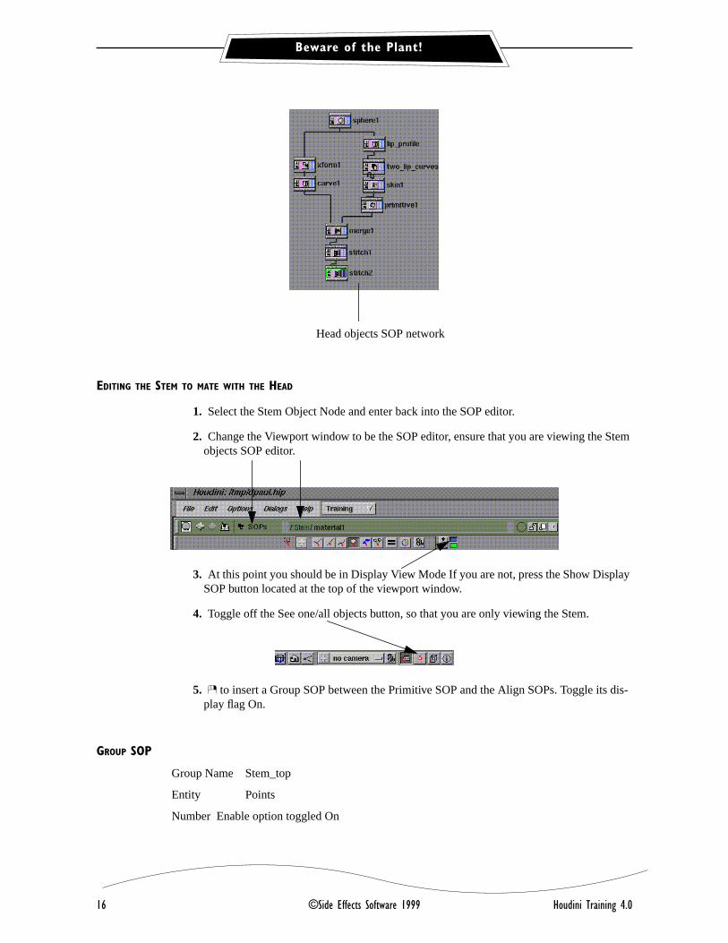
EDITING THE STEM TO MATE WITH THE HEAD
1. Select the Stem Object Node and enter back into the SOP editor.
2. Change the Viewport window to be the SOP editor, ensure that you are viewing the Stemobjects SOP editor.
3. At this point you should be in Display View Mode If you are not, press the Show DisplaySOP button located at the top of the viewport window.
4. Toggle off the See one/all objects button, so that you are only viewing the Stem.
5. \ to insert a Group SOP between the Primitive SOP and the Align SOPs. Toggle its dis-play flag On.
GROUP SOP
Group Name Stem_top
Entity Points
Number Enable option toggled On
Head objects SOP network

Beware of the Plant!
Houdini Training 4.0 ©Side Effects Software 1999 17
Pattern Field set to 0-17
This will group the points at the top of the Stem.
6. Toggle on the See one/all Objects button located at the bottom of the interface to see thefollowing translation in relation to the Head.
TRANSFORM SOP
Group Stem-top (so that only the points in the group are affected by the transformation)
Pivot -1.23 3.3 0.24
Rotate 65 0 -20
Toggle off the Display of primitive number if they are still toggled on.

Beware of the Plant!
18 ©Side Effects Software 1999 Houdini Training 4.0
2.6 CREATING THE INNER MOUTH
1. Change the Editor menu located at the top of the Tile layout window to be Objects.
2. Place a new geometry node in the layout window
name this inner_mouth
change wireframe color to red
parent the Head object to the inner_mouth object node
3. \ on the inner_mouth object tile, and select Edit SOPs from the pop-up menu.
4. Change the viewport window to view the inner_mouth SOP editor.
5. Toggle off the See one/all Objects button.
6. Delete the default file SOP.
OBJECT MERGE
Source head two_lip_curves
DELETE SOP
Toggle on its Display flag
Group 0 1 larger profile curves are deleted
JOIN SOP
Toggle on its Display flag
Toggle the Multiplicity option on to retain hard edge.

Beware of the Plant!
Houdini Training 4.0 ©Side Effects Software 1999 19
SKIN SOP
Ensure that the Skin SOPs display flag is toggled On.
2.7 CREATING THE LIPS
1. Switch the Tile layout window to the Objects editor.
2. Place a new geometry object node in the layout window
name this node lips
in the Misc folder, change the wireframe color to orange 1 .5 0 RGB
parent the Head object to the lip object node
3. Click on the lip tiles pop-up menu. Select Edit SOPs to enter into its SOP editor.
4. Change the viewport window to view the lips SOP editor.
5. Delete the default file SOP.
OBJECT MERGE
Source head lip_profile
JOIN SOP
Defaults
CIRCLE SOP
NURBS
Radius 0.07 0.07
Inner mouth SOP network

Beware of the Plant!
20 ©Side Effects Software 1999 Houdini Training 4.0
SWEEP SOP
Circle is Cross Sectional input
Join is the Backbone input
SKIN
Toggle V wrap option On
1. Ensure that you are in Display SOP mode, and that you have the Display flag of the SkinSOP toggled on.
2. Select the Join SOP to display the associated parameters.
decrease the Tolerance parameter to 0.25 to sharpen the corner at the join point
3. Insert a Primitive SOP between the Sweep SOP and the Skin SOP
Group 4 5 (they are the two circles that make up the middle of the upper lip)
toggle the Do Transformation option On
increase the scale parameter to a value of 3.8
4. Insert another Primitive SOP before the Skin SOP
Group 15 16
toggle the Do Transformation option On
increase the scale parameter to a value of 2
REFINE SOPAppend this SOP to the Skin SOP.
Toggle the U option Off
Toggle the V option On
First V 0.155
Second V 0.18
V Divisions 3
GROUP SOP
Group Name Upper_lip_points
1. * Toggle the Group Sop’s display flag On This is paramount to this routine working.
2. Entity points
3. Toggle the number enable option On. All points will become active.

Beware of the Plant!
Houdini Training 4.0 ©Side Effects Software 1999 21
4. Remove the * from the Pattern Input field No points are active any longer.
5. Toggle the interface into Select Transform State. Located to the right of the viewport win-dow. Change the sub-state to select points.
6. Home the viewport window.
7. Using the left mouse button drag a bounding box over the points that define the curve youinserted with the refine sop. Only these points should be active at this point.
8. Click on the Transfer Selection to Pattern button in the Group SOP’s parameter dialogue.
9. Remember to toggle back into the standard View State mode before continuing.
Do not leave yourself in Select Transform state
10. Before continuing I want you to find the point number of the point at the back of the lipsas indicated in the following illustration.
1) Toggle the display of point numbers on for only the active geometry. If you toggle the display of all points on the screen is simply to busy.
2) Jot down the number of the point shown in the illustration to the left. It is point 212 in this illustration.
3) Toggle the display of point numbers Off once again.

Beware of the Plant!
22 ©Side Effects Software 1999 Houdini Training 4.0
To toggle on the display of selected points, click on the parameter button located tothe right of the viewport window the viewport window.
In the parameter window click on the Point numbers button in the Selected area.
TRANSFORM SOP
Group Upper_lip_points
You will now use a particularly powerful point expression to relocate the pivot point for the group ofpoints to the proper location for the subsequent scaling of this point group. I wanted the pivot point tobe located at the back side of the lip. Works like this:
1. [ Click on the Pivot field of the Transform SOP. This will now enable you to enter expres-sion in the Pivots X Y and Z fields.
Enter the following expression into the X Pivot parameter field. Of course if yourpoint number was not 212 you will use the point number that you determined tobe correct.
point(“../group1”,212,”P”,0)
2. Copy and paste this expression to the Y and Z pivot parameters as well and then make thefollowing edits.
The “P”, 0 changes to “P”, 1 for Y and to “P”, 2 for Z
So your expressions now read:
point(“../group1”,212,”P”,0) point(“../group1”,212,”P”,1) point(“../group1”,212,”P”,2)
Beware of the Plant!
Houdini Training 4.0 ©Side Effects Software 1999 23
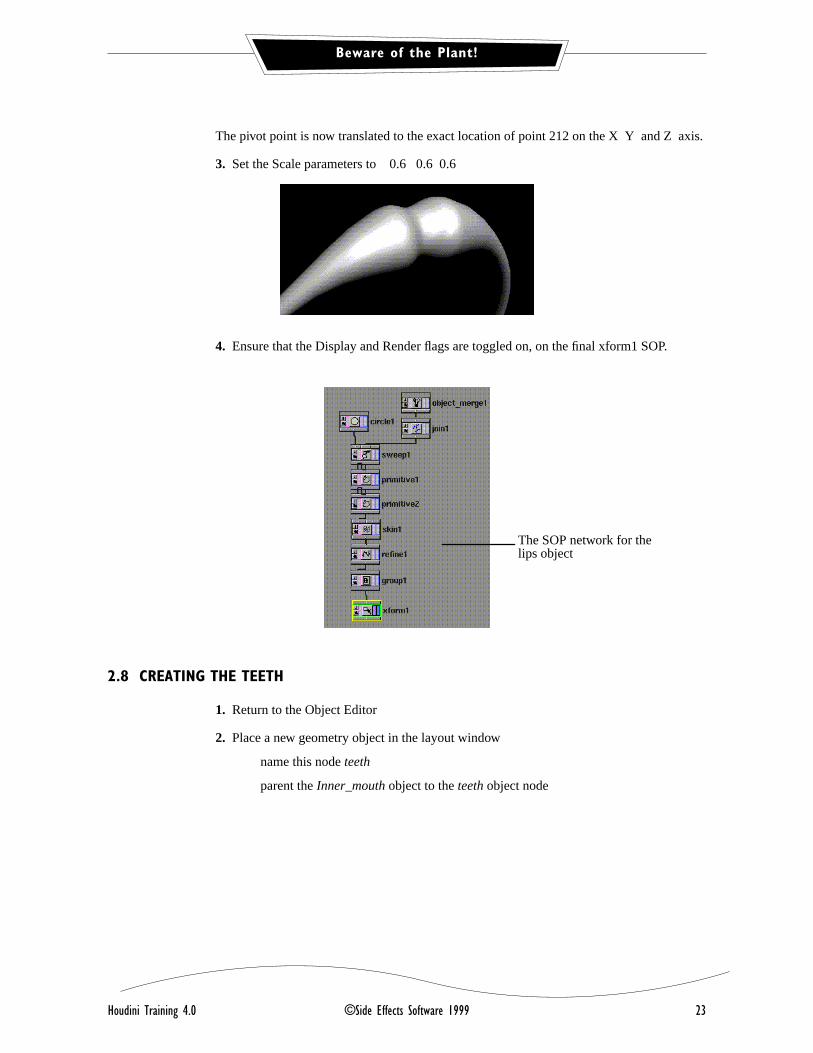
The pivot point is now translated to the exact location of point 212 on the X Y and Z axis.
3. Set the Scale parameters to 0.6 0.6 0.6
4. Ensure that the Display and Render flags are toggled on, on the final xform1 SOP.
2.8 CREATING THE TEETH
1. Return to the Object Editor
2. Place a new geometry object in the layout window
name this node teeth
parent the Inner_mouth object to the teeth object node
The SOP network for the lips object
Beware of the Plant!
24 ©Side Effects Software 1999 Houdini Training 4.0
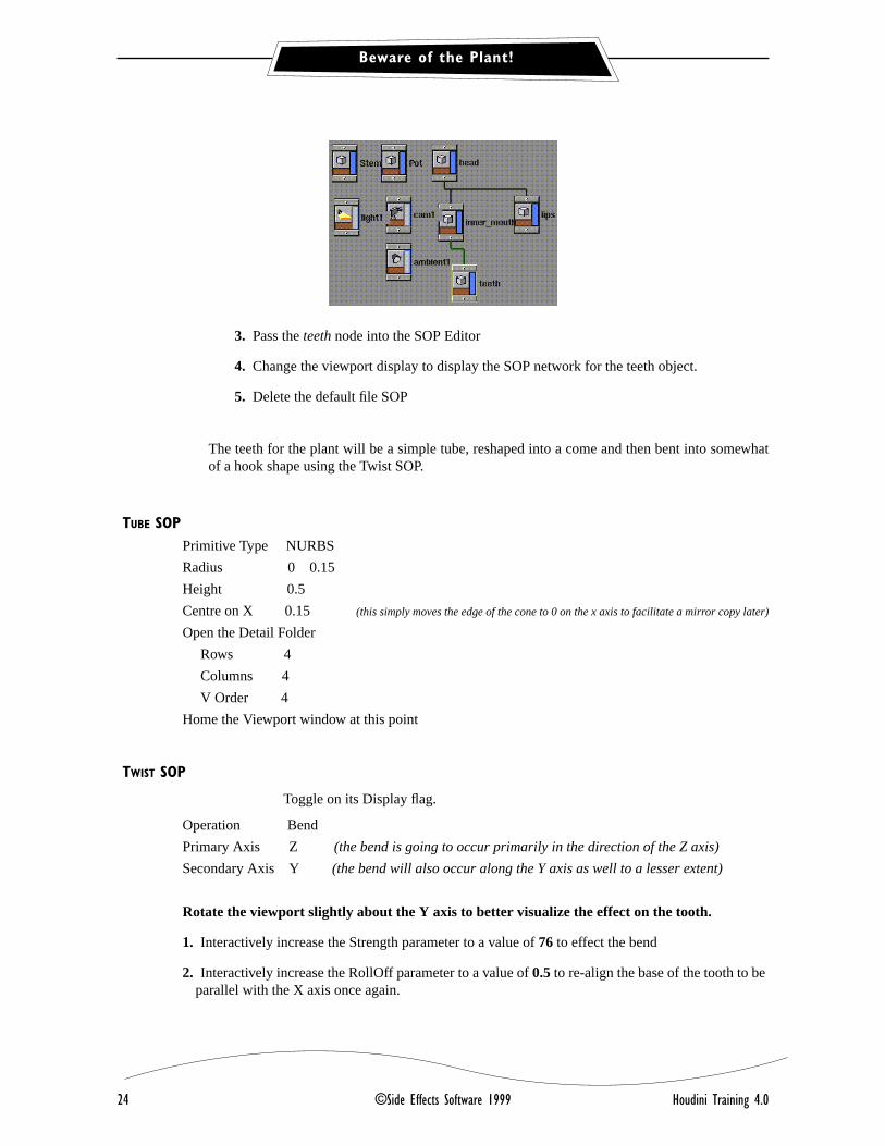
3. Pass the teeth node into the SOP Editor
4. Change the viewport display to display the SOP network for the teeth object.
5. Delete the default file SOP
The teeth for the plant will be a simple tube, reshaped into a come and then bent into somewhatof a hook shape using the Twist SOP.
TUBE SOPPrimitive Type NURBS
Radius 0 0.15
Height 0.5
Centre on X 0.15 (this simply moves the edge of the cone to 0 on the x axis to facilitate a mirror copy later)
Open the Detail Folder
Rows 4
Columns 4
V Order 4
Home the Viewport window at this point
TWIST SOP
Toggle on its Display flag.
Operation Bend
Primary Axis Z (the bend is going to occur primarily in the direction of the Z axis)
Secondary Axis Y (the bend will also occur along the Y axis as well to a lesser extent)
Rotate the viewport slightly about the Y axis to better visualize the effect on the tooth.
1. Interactively increase the Strength parameter to a value of 76 to effect the bend
2. Interactively increase the RollOff parameter to a value of 0.5 to re-align the base of the tooth to beparallel with the X axis once again.

Beware of the Plant!
Houdini Training 4.0 ©Side Effects Software 1999 25
COPY SOP
Toggle on its Display flag
# of Copies 16
Translate on X 0.2
Scale 0.9 0.9 0.9
ALIGN SOP
Toggle on its Display flag
1. Toggle the Individual alignment, translate and rotate options Off.
2. Interactively adjust only the Right U parameter to a value of 0.5
3. Toggle the Translate parameter On
4. Toggle the Individual Alignment parameter On.
5. Adjust the bias parameter to 0 so that the string of teeth are aligned with 0 on the X axis onceagain simply to facilitate a mirror copy of this tooth string later.
OBJECT MERGE SOP
Source Head Skin1
Do not append this SOP to the current net-work chain. Simply place the SOP in thelayout window.
COPY SOPNumber of Copies 2
Scale on X set to -1 The other scale parameters remain unchanged
CREEP SOP
1. Click on the Initialize button and select the Keep Proportions option
• rotate on the X axis -90 You are actually rotating about the U parametric direction.

Beware of the Plant!
26 ©Side Effects Software 1999 Houdini Training 4.0
• rotate on the Z axis -180 You are actually rotating about the W parametric direction
• translate on the Z axis -.45 You are actually translating along the W parametric direction
• translate on the Y axis .2 You are actually translating in the W parametric direction
• scale on the Z axis 2.65 You are actually scaling in the W parametric direction
That takes care of the upper row of teeth keeping everything procedurally linked. The lowerrow of teeth are a little tricky in the instructional set so you will want to follow along care-fully. The Creep SOP only recognizes the first input surface. That is why it ignored the sec-ond surface.
CREATING THE LOWER ROW OF TEETH
1. Using the ] branch append a Delete SOP off of the Object Merge SOP and place it to theleft of the current Creep SOP. Make sure this SOP is not inserted between the ObjectMerge and the Creep SOP.
2. Toggle the Delete SOP’s display flag On and delete primitive number 0, the top surface.
3. Make sure the Creep SOP is the currently active SOP and use the Ac command to copyit.
4. Use the Av command to paste the Creep SOP and place this copy under the Delete SOP.You now have a Creep2.

Beware of the Plant!
Houdini Training 4.0 ©Side Effects Software 1999 27
5. Pipe the output of the Delete1 SOP into the right input node of the Creep SOP as it’s pathinput.
6. Toggle the Creep2 SOP’s display flag On.
All is well except that the teeth are being crept to the wrong side of the path surface. Tocorrect this:
7. Insert a Primitive SOP between the Delete SOP and the Creep SOP and working in theFace/Hull folder:
• change the Vertex option to Reverse U.
8. Append a final Merge SOP to the network chain and ensure that both Creep SOPs arepiped into the merge for display.
9. Don’t forget to toggle the Merge SOPs display and render flags On.
Problem:
The back teeth are intersecting with each other. There are several solutions to thisproblem. One is expensive dental surgery. The other much easier.
10. Toggle the Copy1 SOP on to make it active.
(this is the copy SOP that made 16 teeth out of 1)
You can keep the Display flag of the final Merge SOP on to see the changes as theyfilter down the SOP network.

Beware of the Plant!
28 ©Side Effects Software 1999 Houdini Training 4.0
11. Reduce the number of copies to 13....problem solved!!!
2.9 CREATING THE CROWN OF LEAVES
1. Return to the Object Editor
2. Place a new geometry object node in the layout window
name this object crown
parent the Head object to the crown object node
In its Misc folder, set the wireframe display color to Green.
3. Pass the crown node into the SOP Editor
4. Change the viewport window to be in the crowns SOP editor.
5. Working with the default File SOP.
SOP network for the teeth object.

Beware of the Plant!
Houdini Training 4.0 ©Side Effects Software 1999 29
FILE SOP
1. Navigate to the file crownleaf.bgeo
Home the viewport window
COPY SOP
Toggle on its Display flag
# of Copies 15
Translate on X 0.5
Home the viewport window
GROUP SOP
Toggle on its Display flag
Number Enable
Operation Group by Range
Note that the range is conveniently set to Start at primitive 0 end at Primitive 14 and to select every other primitive
1. Now go back up to the Copy SOP and set the Translate parameter for the X axis back to 0. It wasonly increased initially so that you could easily visualize how the group SOP was processing thegeometry.
XFORM SOPGroup Group 1

Beware of the Plant!
30 ©Side Effects Software 1999 Houdini Training 4.0
Scale 0.7 0.8 1
* Starting a new SOP Chain
OBJECT MERGE
Source head xform1
CARVE SOP
First U 0.25
Second U 0.75
Toggle on Extract
JOIN SOP
1. Toggle the Object Merge SOPs template flag On so you can visualize the head for placement ofthe crown of leaves.
ALIGN SOPThis SOP is appended to the Copy SOP that creates the string of leaves
1. Pipe the Join SOP into the right hand input node to be used as the Auxiliary Source.
2. Toggle the Individual alignment, translate and rotate options Off.
3. Toggle the Translate parameter ON
4. Interactively increase the bias parameter to a value of 1.
5. Interactively increase the Left U parameter to a value of 0.25
6. Toggle the Rotate option On
7. Toggle the Individual Alignment option On.
8. Open the Transform Folder
interactively adjust the Translate Z parameter to a value of -0.8
interactively adjust the Rotate X parameter to a value of -40
interactively adjust the Translate Y parameter to a value of -0.2

Beware of the Plant!
Houdini Training 4.0 ©Side Effects Software 1999 31
interactively adjust the Rotate Z parameter to a value of 180
9. Ensure the Align SOP’s display flag is currently toggled On.
crown objects SOP network

Beware of the Plant!
32 ©Side Effects Software 1999 Houdini Training 4.0
2.10 ADDING SOME CONTROL NULLS
1. Return to the Object Editor and ensure that all objects are being displayed properly. If theyare not, enter into the appropriate SOP networks and toggle On the applicable displayflags.
2. Change the viewport to display Object space.
NULL1Add a Null object to the layout window
name this null Pot_stem
parent this null to the Pot Object node and the Stem object node
NULL2Add a Null object to the layout window
name this null Flower_head
parent this null to the Head Object node
NULL3Add a Null object to the layout window
name this null Complete_plant
parent this null to the Pot_stem null and the Flower_head null
Translate -2.9 -3.3 0
Scale 1.25 (this is the Uniform scale parameter)

Miscellaneous
Houdini Training 4.0 ©Side Effects Software 1999 33
2.11 USING THE OPREAD COMMAND
To the students
In the interest of time, the bird cage was saved out as a component from a completed file using theopwrite command. The object nodes to write out were named null1, feathers cage and support. Usingtextport commands, this is how that was done.
opcf /obj
opwrite /obj/null1 feathers cage support /[workingdirectory]/import1.hip
1. In the main viewport window, change it to Texport.
2. You will now read this geometry into the current file using the opread command. In thetexport use the following commands.
opcf /obj
opread /[current directory where training files are stored]/import1.hip
If you have a lot of operators to write out it is easier to assemble them into a group Edit > Edit Obj Groups.Assuming I had created an object group called head;
opwrite /obj/@head /[working directory]/import1.hip
1 MISCELLANEOUS
SOIL
The pot currently has no bottom, nor has it soil. Consequently the plant appears thatit is floating in the air.
SO:
1. Return the viewport from Textport to Viewer.
2. Add a new geometry object. Rename it to Soil
Parent the Pot object to the Soil object.
Enter into the Soil objects SOP editor.
Change the Main viewport to be the Soil Objects SOP editor.
Delete the Default File SOP.
OBJECT MERGE SOP
Source 1 Pot

Miscellaneous
34 ©Side Effects Software 1999 Houdini Training 4.0
SOP Display SOP
FACET SOP
Toggle on its DIsplay flag
In the Consolidate field change it to Consolidate Points Fast
CONVERT SOP
Change the Convert to field to
If you toggle on the information button of the Convert SOP, you will notice that youhave 2 mesh surfaces. One is a partial section of the Pot object. You want to carveout a curve out of the inner part of the Pot. You will then Skin that to make a surfacebased on the area of the Pot. First you have to delete the extraneous surface.
DELETE SOP
Group 1
CARVE SOP
Toggle on its DIsplay flag
First U 0.15
SKIN SOP
Toggle on its Display flag
Leave it at its defaults
CONVERT SOP
Display flag on
Convert To NURBS Surface
TRANSFORM SOP
Scale 1.1 0 1.1
FRACTAL SOP
Toggle on its Display and Render flags

Some Evil Eyes?
Houdini Training 4.0 ©Side Effects Software 1999 35
Change the Direction to 0 1 0
Increase the Divisions to 3
Decrease the Smoothness value to 0.45
Decrease the Scale parameter down to 0.07
Change the main viewport window to view Object space. Now the Plant is lookingmore complete.....how about some eyes?
Have you saved lately?
1 SOME EVIL EYES?
CREATING THE EYE SOCKET
In the Tile layout window navigate up to the Object editor
Keyboard Shortcut: (the u key will do this)
Place a new node in the Object Tile layout window and rename it: eyes
Enter into its SOP editor
Keyboard shortcut: (the i key will do this)

Some Evil Eyes?
36 ©Side Effects Software 1999 Houdini Training 4.0
Delete the default File SOP
Change the main viewport window to be viewing the eyes SOP editor.
*** Ensure the viewport display mode is set to Display SOP
SPHERE SOP
Primitive Type NURBS
Orientation X axis
Radius 1 0.4 0.5
TRANSFORM SOP
Rotate 180 0 0
CARVE1
Toggle on its DIpslay flag
First U 0.199
Second U 0.994
3. While displaying the output of the Carve SOP, select the Transform SOP and adjust therotate parameter for the X axis to a value of 1700.

Some Evil Eyes?
Houdini Training 4.0 ©Side Effects Software 1999 37
TWIST SOP
Toggle on its Display flag
Home the viewport window
Strength 18
This simply gives the eyes some character and makes them look a little more sinister.
TRANSFORM SOP
Toggle on its Display flag
Translate -1.2 0 0
Rotate 0 0 10
COPY SOP
Display Flag
# of copies 2
scale -1 1 1
PRIMITIVE SOP
Display Flag
1. Open the Attributes Folder.
2. Change Keep Color to Add Color.
3. Delete the current color channel (T \ on the color field button).
Select Delete Channels

Some Evil Eyes?
38 ©Side Effects Software 1999 Houdini Training 4.0
4. Set the color parameters to 0 1 0
ANIMATING THE CARVE SOP TO CREATE A BLINK
1. While displaying the output of the Primitive SOP, select the Carve SOP to display its associatedparameters.
2. [ on the First U field to enable you to enter expressions.
Enter the following expression in the Parameter field:
abs(cos($F*5))*.2
3. Playback the animation at this point, and although the eyes will blink, there is an obvious prob-lem.
Essentially the blink is backwards. Or is it. It simply depends on the effect you want to achieve. How-ever, assuming that you want the upper eyelid animated rather than the lower eyelid:
4. Select the Xform1 SOP to display its associated parameters and:
Rotate the geometry 1800 about the Z axes. (set the Z Rotate parameter to 180)
The upper eyelid now closes down as you might have expected.

Some Evil Eyes?
Houdini Training 4.0 ©Side Effects Software 1999 39
1.1 CREATING THE EYE BALL
1. Select the Copy1 SOP ensuring it is the only currently active SOP.
2. Using the Right mouse button click on the SOP’s pictorial icon and choose the option Selectinputs from the associated pop-up menu.
At this point all SOPs in the chain above the Copy SOP should be active.
3. Use the Ac keyboard combination to copy the selected SOPs.
4. Use the Av keyboard combination to paste the SOPs.
Move this new chain of SOPs over to the right of the current chain of SOPs.
5. Select the Carve2 SOP to display its associated parameters and:
toggle the Keep Inside option Off
toggle the Keep Outside option On
You now have the opposite Carve geometry which represents the eye balls themselves.
MERGE1
Place a Merge SOP beneath the two chains
Toggle its Display flag on
Pipe the Primitive SOP into the Merge1 SOP.
Pipe the Copy2 SOP into the Merge SOP
1. Play back the animation at this point. (Try it is shaded mode)
2. Return to frame 1.

Some Evil Eyes?
40 ©Side Effects Software 1999 Houdini Training 4.0
1.2 CREATING THE PUPILS
The SOP chain that you copied earlier is still in the copy buffer, therefore:
1. Use the Av keyboard combination to copy this SOP chain once again and move the chain overto the right of the last chain.
2. Toggle the Copy3 SOPs display flag On.
3. Select the Carve3 SOP to display its associated parameters and:
toggle the Keep Inside option Off
toggle the Keep Outside option On
4. Using the Right mouse button, insert another Carve SOP between the existing Carve3 SOP andthe Twist SOP. Working with this new Carve SOP:
Toggle the First U option Off
Toggle the First V option On and set the parameter to a value of 0.441
Toggle the Second V option ON and set the parameter to value of 0.501
5. Toggle on the Display flag of the final Merge SOP.
Connect the output of the Copy3 SOP (the last SOP in this chain) to the Merge SOPfor final display and toggle the display into Shaded Mode.
6. Insert a Primitive SOP between the Copy3 SOP and the Merge SOP and working with the Primi-tive SOP parameters:
open the attributes folder
set the option to Add Color
delete the current Color Attribute channel
set the color parameters to 0 0 0 to create a set of black pupils
You will likely encounter some bleed through shading of the eyeball surface on the pupil surface.This is due to the fact that both of these surface currently occupy the same shading space. To cor-rect this, the pupil surface must be offset very slightly from the eye ball surface. To do this easily:
7. Return to the Transform folder of the Primitive SOP:
toggle the Do Transformation button On
set the Translate parameter for the Z axis to a value of 0.001

Some Evil Eyes?
Houdini Training 4.0 ©Side Effects Software 1999 41
It will be up to you to decide how the eyes can be positioned on the top of the plant.
Don’t forget to save your file again if you have not been doing so.

Appendix
42 ©Side Effects Software 1999 Houdini Training 4.0
1 APPENDIX
If you don’t have the geo file for the pot profile you can easily construct it from these directions.
1. Pass the Model SOP into the modeller. But rather then trying to open the geo file that youdon’t have........
2. Set up to create a Polygon Curve.
3. Place 7 points in somewhat of a straight line in the front window. It doesn’t matter wherethe points are. Simply place 7 points in the front window.
4. Display the Geometry Spreadsheet. This is done by selecting Geometry spreadsheet fromany one of the viewport selection menus.
5. Working with the geometry spreadsheet relocate the points to the following coordinates onx y and z respectively:
Point 0 -1.3 -1 0
Point 1 -1.8 1.2 0
Point 2 -2.2 1.2 0
Point 3 -2.2 1.7 0
Point 4 -1.5 1.7 0
Point 5 -1.5 1.4 0
Point 6 -.95 -0.74 0

Appendix
Houdini Training 4.0 ©Side Effects Software 1999 43
1.1 A FINAL WORD
The Primitive SOP is very versatile and can be used very effectively to move the Pivot point tothe centroid of the Primitive input to it as you saw in this exercise. However, there are times whenthe input to the Primitive SOP will be more than one single primitive.
When multiple primitives are being passed to the Primitive SOP, the SOP addresses each of thePrimitives individually and thus each primitive rotates around its own local centroid. (UsingRotate as an example of course)
To address the centroid of the entire set of Primitive being passed to the Primitive SOP use a bboxexpression. Of course, one could use a Transform SOP instead.
Enter these expressions in the Pivot X Y Z fields
For X (bbox(“../facet1”,D_XMIN)+bbox(“../facet1”,D_XMAX))/2
For Y (bbox(“../facet1”,D_YMIN)+bbox(“../facet1”,D_YMAX))/2
For Z (bbox(“../facet1”,D_ZMIN)+bbox(“../facet1”,D_ZMAX))/2
Save these expressions as a Preset and consider using a SOP name such as Centroid rather than the namefacet1 used here. Then whenever you want this functionality recall the preset to the Primitive SOP andsimply rename the SOP that the passing the Primitives to the SOP to be Centroid.
Default Grid SOP
Toggle on Unique Points
Rotate on Y -50

Appendix
44 ©Side Effects Software 1999 Houdini Training 4.0