xeus payload definition document - esaemits.sso.esa.int/emits-doc/4964-rd2-xeus_pdd.pdf ·...
TRANSCRIPT

XEUS
PAYLOAD DEFINITION DOCUMENT
prepared by/ préparé par SCI-AM (input from SCI-AT) reference/réference SCI-A/2005/139/DL issue/ édition 3 revision/ révision 1 date of issue/date d’édition 16/03/2006 status/état Draft Document type/type de document Technical Note Distribution/ distribution Public document

XEUS PDD Issue 3 Revision 1 – SCI-A/2005/139/DL
page 2 of 70
s
A P P R O V A L
Title titre
issue issue
3 revision revision
1
author auteur
date date
approved by approuvé by
date date
C H A N G E L O G
reason for change /raison du changement issue/issue revision/ revision date/date
First release & preparation for CDF activity Including updates resulting from CDF studies Overall update Revision based on payload working group and instrument experts inputs & responsive to SciRD Internal review and further harmonisation to 35m concept ready for the payload accommodation study
1 2 2 3 3
0 0 1 0 1
21/05/2004 March/2005 April/2005 Sep/2005 March/2006
C H A N G E R E C O R D M A R C H / 2 0 0 6
Issue: 3 Revision: 1
reason for change/ raison du changement page(s)/page(s) paragraph(s)/paragraph(s)

XEUS PDD Issue 3 Revision 1 – SCI-A/2005/139/DL
page 3 of 70
s TABLE OF CONTENTS
PART 1 PREFACE 6
1 List of acronyms .....................................................................................................................7 2 Reference list ..........................................................................................................................9 3 Spacecraft Reference cooordinate system.......................................................................... 10 4 Introduction.......................................................................................................................... 11 5 Contact Persons.................................................................................................................... 12 6 Payload Procurement– Announcement of Opportunity.................................................. 13 7 Payload overview.................................................................................................................. 14
7.1 Core payload complement...............................................................................................14 7.2 High priority augmentation .............................................................................................14
8 Mission profile & science operations - summary.............................................................. 15 8.1 Earth Communications....................................................................................................16
PART 2 DESCRIPTION OF THE BASELINE INSTRUMENTS 17
1 Introduction.......................................................................................................................... 18 1.1 Wide Field Imager (WFI) ................................................................................................20
1.1.1 Scientific Goals .............................................................................................................20 1.1.2 Instrument concept ........................................................................................................20 1.1.3 Operations .....................................................................................................................25 1.1.4 Pointing Requirements...................................................................................................25 1.1.5 Thermal ........................................................................................................................25 1.1.6 Accommodation ............................................................................................................26 1.1.7 Interface and Physical Resource Requirements ................................................................26 1.1.8 Cleanliness, Ground Operations and Other Requirements .................................................27 1.1.9 Open Points and Critical Issues.......................................................................................28
1.2 Narrow Field Imager 1 (NFI 1) ........................................................................................29 1.2.1 Scientific Goals .............................................................................................................29 1.2.2 Instrument concept ........................................................................................................29 1.2.3 Operations .....................................................................................................................31 1.2.4 Pointing Requirements...................................................................................................31 1.2.5 Thermal ........................................................................................................................31 1.2.6 Accommodation ............................................................................................................31 1.2.7 Interface and Physical Resource Requirements ................................................................32 1.2.8 Cleanliness, Ground Operations and Other Requirements .................................................33 1.2.9 Open Points and Critical Issues.......................................................................................33
1.3 Narrow Field Imager 2 (NFI 2) ........................................................................................34 1.3.1 Scientific Goals .............................................................................................................34 1.3.2 Instrument concept ........................................................................................................34 1.3.3 Operations .....................................................................................................................36 1.3.4 Pointing Requirements...................................................................................................37 1.3.5 Thermal ........................................................................................................................37 1.3.6 Accommodation ............................................................................................................37 1.3.7 Interface and Physical Resource Requirements ................................................................37
XEUS PDD Issue 3 Revision 1 – SCI-A/2005/139/DL
page 4 of 70
s 1.3.8 Cleanliness, Ground Operations and Other Requirements .................................................39 1.3.9 Open Points and Critical Issues.......................................................................................39
PART 3 DESCRIPTION OF THE ANCILLARY INSTRUMENTS 41
1.4 Hard X-ray Camera (HXC).............................................................................................42 1.4.1 Scientific Goals .............................................................................................................42 1.4.2 Instrument concept ........................................................................................................42 1.4.3 Operations .....................................................................................................................43 1.4.4 Pointing Requirements...................................................................................................44 1.4.5 Thermal ........................................................................................................................44 1.4.6 Accommodation ............................................................................................................44 1.4.7 Interface and Physical Resource Requirements ................................................................45 1.4.8 Cleanliness, Ground Operations and Other Requirements .................................................46 1.4.9 Open Points and Critical Issues.......................................................................................47
1.5 High Time Resolution Spectrometer (HTRS)...................................................................48 1.5.1 Scientific Goals .............................................................................................................48 1.5.2 Instrument concept ........................................................................................................48 1.5.3 Operations .....................................................................................................................49 1.5.4 Pointing Requirements...................................................................................................50 1.5.5 Thermal ........................................................................................................................50 1.5.6 Accommodation ............................................................................................................50 1.5.7 Interface and Physical Resource Requirements ................................................................51 1.5.8 Cleanliness, Ground Operations and Other Requirements .................................................52 1.5.9 Open Points and Critical Issues.......................................................................................52
1.6 X-ray Polarimeter (XPOL) ................................ ................................ ..............................53 1.6.1 Scientific Goals .............................................................................................................53 1.6.2 Instrument concept ........................................................................................................54 1.6.3 Operations .....................................................................................................................56 1.6.4 Pointing Requirements...................................................................................................56 1.6.5 Thermal ........................................................................................................................57 1.6.6 Accommodation ............................................................................................................57 1.6.7 Interface and Physical Resource Requirements ................................................................57 1.6.8 Cleanliness, Ground Operations and Other Requirements .................................................58 1.6.9 Open Points and Critical Issues.......................................................................................59
PART 4 PAYLOAD ACCOMMODATION AND INTERFACES 60
1 Introduction.......................................................................................................................... 61 2 Accomodation....................................................................................................................... 62 3 Payload support elements (PSE)......................................................................................... 63 4 Interfaces............................................................................................................................... 64
4.1 Data handling system.......................................................................................................64 4.2 Power...............................................................................................................................64 4.3 Thermal...........................................................................................................................64 4.4 Cryogenics .......................................................................................................................65
4.4.1 Thermal interfaces .........................................................................................................66 4.5 Baffling............................................................................................................................66
XEUS PDD Issue 3 Revision 1 – SCI-A/2005/139/DL
page 5 of 70
s 4.5.1 WFI Baffle ....................................................................................................................67
4.6 Pointing requirements .....................................................................................................67 4.6.1 Pointing Requirements...................................................................................................67 4.6.2 Mirror Alignment ................................ ................................ ................................ ..........68 4.6.3 Formation Flying Requirements................................ ................................ ......................68
5 ESA / Platform provided items ........................................................................................... 69 5.1 Cryogenic Elements.........................................................................................................69
5.1.1 20 K Stirling Cooler.......................................................................................................69 5.1.2 2.5 K Joule Thomson Cooler ................................ ................................ ..........................69 5.1.3 Sorption cooler ................................ ................................ ................................ ..............69 5.1.4 Adiabatic Demagnetisation Refrigerator ................................ ................................ ..........70

XEUS PDD Issue 3 Revision 1 – SCI-A/2005/139/DL
page 6 of 70
s
Part 1 Preface The Payload Definition Document (PDD) is agreed by all the contributors listed below to describe a reference payload that satisfies the measurements requirements given in the Science Requirements Document [RD-SciRD]. This reference payload has been used to establish the overall system design and the corresponding cost envelope. Payload Working Group chairman:
- Piet De Korte, SRON Utrecht Payload Working Group contact persons as defined in Part 1 chapter 5.

XEUS PDD Issue 3 Revision 1 – SCI-A/2005/139/DL
page 7 of 70
s
1 LIST OF ACRONYMS
AC Alternating Current ADC Analog to Digital Converter ADR Adiabatic Demagnetisation Refrigerator AGN Active Galactic Nuclei AIV Assembly, Integration and Verification AOCS Orbit and Attitude Control System APD Avalanche PhotoDiodes APS Active Pixel Sensor ASIC Application Specific Integrated Circuit BGO Bi4Ge3O12 CAN Controller Area Network CEU Central Electronic Unit CPPS Centralized Payload Power Supply CRB Contamination Review Board CSA Charge Sensitive Amplifier DAC Digital to Analog Converter DC Direct Current DEPFET Depletion Mode Field Effect Transistor DPU Digital Processing Unit DSP Digital Signal Processor EMC Electromagnetic Cleanliness/compatibility EMCB Electromagnetic Cleanliness Board EMI Electromagnetic Interference EOL End of Life FEE Front End Electronics FET Field Effect Transistor FPGA Field Programmable Array GEM Gas Electron Multiplier HGA High Gain Antenna HTRS High Time Resolution Spectrometer H/W Hardware HXC Hard X-ray Camera ICU Instrument Control Unit I/O Input/Output J-T Joule-Thomson (cooler) LOS Line Of Sight MLI Multi Layer Insulation NFI Narrow Field Imager PA Product Assurance PDD Payload Definition Document PDMU Payload Data Management Unit PSU Power Supply Unit RAM Random Access Memory

XEUS PDD Issue 3 Revision 1 – SCI-A/2005/139/DL
page 8 of 70
s RTU/C Remote Terminal Unit / Control S/C Spacecraft SCI-A Science Payload & Advanced Concepts Office SciRD Science Requirements Document SDD Single Drift Diode SNR Super Nova Remnant SpW Space Wire SSMM Solid State Mass Memory STE Supra-Thermal Electron detector STJ Super conducting Tunnel Junction SWT Science Working Team SXRP Stellar X-Ray Polarimeter TBC To Be Confirmed TBD To Be Determined TC/TM Tele-command / Telemetry TDA Technology Development Activity TDP Technology Development Plan TES Transition Edge Sensor WFI Wide Field Imager XRB X-ray Binary

XEUS PDD Issue 3 Revision 1 – SCI-A/2005/139/DL
page 9 of 70
s
2 REFERENCE LIST
[RD-1] XEUS Science Requirements Document [RD-2] Instrument Working Group report [RD-3] Concurrent Design Facility Report [RD-4] XEUS Detector Spacecraft Definition Document [RD-5] Constellation-X IMDC study report

XEUS PDD Issue 3 Revision 1 – SCI-A/2005/139/DL
page 10 of 70
s
3 SPACECRAFT REFERENCE COOORDINATE SYSTEM
The Spacecraft Co-ordinate Systems are axis reference frames physically attached to the respective spacecraft. All reference frames shall be right-handed orthogonal triads. The MSC Geometrical Fixed Reference Frame shall be defined as in Table 1
Item Definition
Origin In the geometric center of the mirror face in the direction of the telescope focal point +X Normal to the Z axis, pointing towards the MSC sunshield +Y Axis that is completing the right-handed orthogonal triad (Y = Z x X) +Z Along the boresight of the telescope pointing towards the mirror incoming photons
Table 1 MSC Geometrical Fixed Reference Frame
The DSC Geometrical Fixed Reference Frame shall be defined as in Table 2
Item Definition Origin In the geometric center of the spacecraft face opposite the face containing instrument apertures +X Normal to the Z axis pointing towards the Sun face of the DSC +Y Axis that is completing the right-handed orthogonal triad (Y = Z x X) +Z Along the boresight of the telescope pointing towards direction of the face containing the
instrument apertures Table 2 DSC Geometrical Fixed Reference Frame
Each instrument will have its local co-ordinate system that is nominally parallel with the DSC system, except where geometric alignments of special features may dictate another logic.

XEUS PDD Issue 3 Revision 1 – SCI-A/2005/139/DL
page 11 of 70
s
4 INTRODUCTION
This Payload Definition Document (PDD) is a compilation of the XEUS reference payload requirements and of their related reference design. The PDD plays a key role in defining the resources required by the XEUS instruments and in providing the information necessary to conduct the mission assessment study and the preliminary spacecraft design. The model payload described in this document originates from the scientific objectives of the XEUS mission as spelled out in the associated Scientific Requirements Document [RD1]. Information on the reference payload has been provided by selected experts of the XEUS Instrument Working Group. The initial descriptions were provided in the Instrument Working Group report [RD-2] and then used as a basis for the preliminary versions of the PDD. Since those first compilations, an internal study of the XEUS mission was carried out in the Concurrent Design Facility (and reported in [RD-3]), but this concerned mainly the Mirror Spacecraft (MSC) elements, and where the Detector Spacecraft (DSC) was taken with a baseline of 3 core instruments and estimated resources, not subject to verification. As a consequence of the study of MSC sub-systems and the initial PDD, a DSC definition Document [RD-4] was produced. A study of a DSC version in the context of the Constellation-X project was carried out in the NASA GSFC Integrated Mission Design Center activity, and reported in [RD-5]. However this include d mainly payload elements related to the NASA mission, and not representative of the XEUS payload. Subsequently, the XEUS Science Advisory Team has been preparing an updated science case in the context of submissions to the Cosmic Visions 2025 programme, and comparing the science case with that of the NASA Con-X project with a view to internationalising and harmonizing the project. As a result, the XEUS Science Requirements Document was provided and the PDD revised to support a payload that fully meets the required objectives. In the course of that activity, it was realized that a severe and unsustainable mass growth in the DSC would occur, and that some descoping of objectives was necessary. This version of the document is the result of such descoping, wit h re-submission from the instrument experts. The payload information was also reviewed and amended by the SCI-A (Science Payload and Advanced Concepts Office). The early assessment showed that the previously identified payload resources were largely under-estimated, especially with respect to the growth of field of view requirements and spectral resolution requirements that drive the design and the resources of cryogenic instruments. These thermal issues were also found to have a major impact on system resources and spacecraft design, and had not been adequately researched. Given its key role and large impact on the system design, it is assumed that the cryogenic chain will be spacecraft rather than instrument provided.

XEUS PDD Issue 3 Revision 1 – SCI-A/2005/139/DL
page 12 of 70
s
5 CONTACT PERSONS
Instrument Acronym Name Address Telephone FAX E-mail Wide Field
Imager WFI L Strüder MPI Halbleiterlabor
Otto-Hahn-Ring 6, 81739 München +49 (89) 8394000 +49 (89) 83
94 0011 [email protected]
Narrow Field Imager
1
NFI 1 D Martin ESTEC SCI -A, Keplerlaan 1, Postbus 299, 2200AG Noordwijk
+31 715653577 +31 715654690
Narrow Field Imager
2
NFI 2 P de Korte Sorbonnelaan 2 3584 CA UTRECHT
+31 (0)302535710 +31 (0)30-2540860
Hard X-ray Camera
HXC T Takahashi
C Budtz-Jorgensen
Institute of Space and Astronautical Science, 3-1-1Yoshinodai, Sagamihara, Kanagawa, 229-8510 Danish National Space Center Juliane Maries Vej 30, 2100 Copenhagen
+45 35325726
+45 35362475
High Time Resolution
Spectrometer
HTRS D Barret CESR - Centre d'Etude Spatiale des Rayonnements
9 avenue du Colonel Roche 31028 Toulouse
+33 0561558371 +33 056155670
1
X-Ray Polarimeter
XPOL E Costa Via del Fosso del Cavaliere 100, 00133 Roma
+39 06/4993-4004 +39 - 06206 0188

Issue 3 Revision 1 – SCI-A/2005/139/DL
page 13 of 70
s
6 PAYLOAD PROCUREMENT– ANNOUNCEMENT OF OPPORTUNITY
If XEUS were to be included as a mission in the forthcoming Cosmic Visions 2025 programme, it would be the intention of the European Space Agency to release an Announcement of Opportunity (AO) for the provision of the XEUS instruments. In order to take maximum advantage from the work done (e.g., PDD input, payload and system level industrial activities, technology development plan, etc.), and avoid changes that could have a significant impact on the mission profile and associated cost envelope, the future Request For Proposal of the AO, without limiting the detailed design of the instruments, would be based on the present Payload Definition Document and provide specific boundary conditions. In particular, the AO would be expected to make reference (in the form of both boundary conditions and reference requirements) to the resource budgets, overall accommodation and key interface aspects listed in this document. This procedure will allow guaranteeing full compatibility with the ongoing work at spacecraft level as well as to minimize the development risks associated with the approval of the payload complement. It is in fact clear from the results of the assessment study that, given both the technical challenges and the programmatic constraints applicable to this mission, design solutions implying a total nominal instrument mass approaching 350 kg (including cryogenic coolers) would impact directly on the overall spacecraft design with the effect of:
• Reducing the contingency margins to an unacceptable level, thus forcing the reduction in corresponding mass of MSC (and hence effective mirror collection area)
• Increasing the total cost of the mission to a level incompatible with the available resources • Force the adoption of new technology to be qualified for space flight, thus leading to potential
delays • Increasing the development risks at both spacecraft and instrument level, with a related cost impact
on the respective funding Agencies.

Issue 3 Revision 1 – SCI-A/2005/139/DL
page 14 of 70
s
7 PAYLOAD OVERVIEW
The payload is organised into the core payload that fulfils the main science requirements. In addition to the core payload, high priority augmentation instruments are identified which should be considered should resources allow.
7.1 Core payload complement The Baseline Mission could be accomplished by an instrument complement comprising the
following: • Wide Field Imager • Narrow Field Imager
Presently two different Narrow Field Instrument designs are available:
1) NFI1 is based on a focal plane of super conducting tunnel junctions (STJ), operated at a temperature of < 300 mK via a 3He Sorption Cooler (or as an alternative an Adiabatic Demagnetisation Refrigerator (ADR) if temperature below 250 mK are required).
2) NFI2 is based on a focal plane array of micro-calorimeters, operated at about 50 mK via an ADR; In consideration of the expected launcher performance and of the resource demands of both Detector Spacecraft and Mirror Spacecraft, it has been assumed to limit the model payload to the Wide Field Camera and a single Narrow Field Imager. Given the early definition stage of the mission, it is not possible to m ake a definitive choice on the actual NFI design and therefore both designs will be analysed in the context of the XEUS payload accommodation study. In other terms, both configurations (WFI + NFI1 and WFI + NFI2) will be investigated, including different cryogenic chain designs, based on ADR and spacecraft units.
7.2 High priority augmentation The following instruments are to be considered in addition to the core payload should resources be sufficient:
• High Time Resolution Spectrometer • Hard X-ray Camera • Narrow Field Imager (2nd unit) • X-ray Polarimeter

Issue 3 Revision 1 – SCI-A/2005/139/DL
page 15 of 70
s
8 MISSION PROFILE & SCIENCE OPERATIONS - SUMMARY
The baseline mission design elaborated in the CDF study considers a single launch of DSC and MSC via either Ariane V or Delta IV Heavy, into a halo orbit around L2. The transfer orbit will be designed so that insertion occurs at the point of maximum out of plane amplitude and consequently with zero velocity insertion manoeuvre. This simple orbit design removes the need for additional propulsion units. However the upper stage liquid propellant will require launch dispersion correction of ~25 m/s within 2 days of launch, followed by a trim correction at 8 days (2m/s) and a mid-course correction manoeuvre of 1m/s. The total cruise duration to L2 depends on launch date and may be 3-5 months. Eclipse duration during LEOP should last less than 75 minutes. The two spacecraft then fly as a stack to the orbit around L2. A number of mission phases are envisaged, as summarised below: Launch From lift-off to separation. Expected duration 30 minutes. Only essential sub-systems are on, possibly to include heaters and other environment control. GNC and communications equipment off Initialisation Nominal duration ~2 days. Launch dispersion will be corrected, stack acquires attitude ready for cruise. Order of actions may be: § Mode-required sub-systems are switched on § tip-off rates cancelled § Dispersion correction performed according to ground control § Stack XZ plane and sun vector oriented to avoid star tracker looking into Sun
Cruise Only attitude control manoeuvres will be needed during cruise phase. The cruise phase is also used to outgas the spacecraft and its instruments. Hence all doors will remain closed during cruise. Deployment Spacecraft will separate and acquire safe position and attitude, and achieve null relative velocity. Solar arrays maximally exposed to Sun. For the DSC that is relevant to payload, the following sequence applies: § Cancel angular momentum from separation manoeuvre § Orient axis correctly for sun vector § Re-establish communications with ground station and MSC § Deploy baffle system (s) if deployable baffles are used § Establish safe hold FF distance § Cancel translation rates with MSC
Commissioning Mode The DSC instrument sub-systems will be switched on and run through general tests. Cryogenic sub-systems can be activated and cooled down. The time to reach operational temperature can be dictated by
Issue 3 Revision 1 – SCI-A/2005/139/DL
page 16 of 70
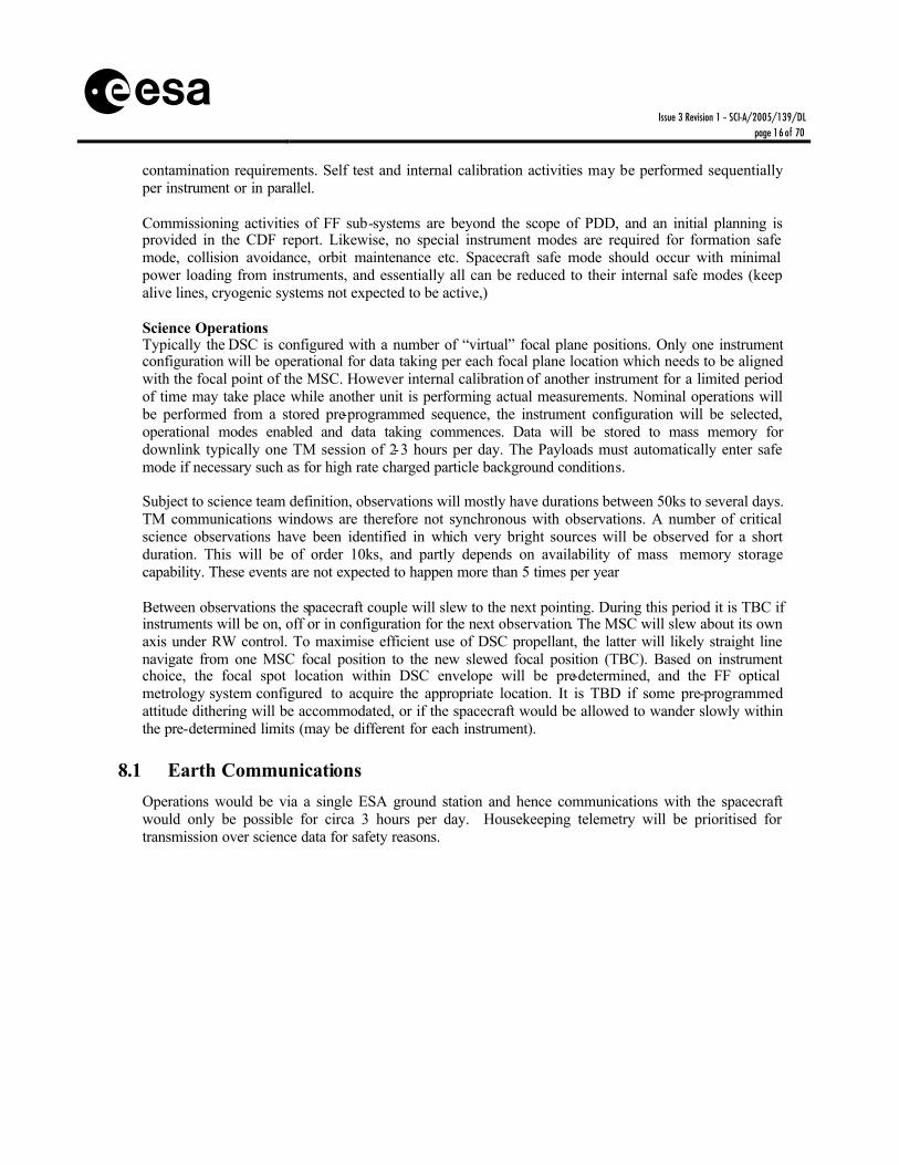
s contamination requirements. Self test and internal calibration activities may be performed sequentially per instrument or in parallel. Commissioning activities of FF sub-systems are beyond the scope of PDD, and an initial planning is provided in the CDF report. Likewise, no special instrument modes are required for formation safe mode, collision avoidance, orbit maintenance etc. Spacecraft safe mode should occur with minimal power loading from instruments, and essentially all can be reduced to their internal safe modes (keep alive lines, cryogenic systems not expected to be active,) Science Operations Typically the DSC is configured with a number of “virtual” focal plane positions. Only one instrument configuration will be operational for data taking per each focal plane location which needs to be aligned with the focal point of the MSC. However internal calibration of another instrument for a limited period of time may take place while another unit is performing actual measurements. Nominal operations will be performed from a stored pre-programmed sequence, the instrument configuration will be selected, operational modes enabled and data taking commences. Data will be stored to mass memory for downlink typically one TM session of 2-3 hours per day. The Payloads must automatically enter safe mode if necessary such as for high rate charged particle background conditions. Subject to science team definition, observations will mostly have durations between 50ks to several days. TM communications windows are therefore not synchronous with observations. A number of critical science observations have been identified in which very bright sources will be observed for a short duration. This will be of order 10ks, and partly depends on availability of mass memory storage capability. These events are not expected to happen more than 5 times per year Between observations the spacecraft couple will slew to the next pointing. During this period it is TBC if instruments will be on, off or in configuration for the next observation. The MSC will slew about its own axis under RW control. To maximise efficient use of DSC propellant, the latter will likely straight line navigate from one MSC focal position to the new slewed focal position (TBC). Based on instrument choice, the focal spot location within DSC envelope will be pre-determined, and the FF optical metrology system configured to acquire the appropriate location. It is TBD if some pre-programmed attitude dithering will be accommodated, or if the spacecraft would be allowed to wander slowly within the pre-determined limits (may be different for each instrument).
8.1 Earth Communications Operations would be via a single ESA ground station and hence communications with the spacecraft would only be possible for circa 3 hours per day. Housekeeping telemetry will be prioritised for transmission over science data for safety reasons.

Issue 3 Revision 1 – SCI-A/2005/139/DL
page 17 of 70
s
Part 2 Description of the Baseline Instruments

Issue 3 Revision 1 – SCI-A/2005/139/DL
page 18 of 70
s
1 INTRODUCTION
In this part, the baseline design of each instrument is described and the corresponding resources, in terms of mass, envelope size, power and data rate are quantified. Such estimates play an important role in the context of the definition of the XEUS mission as they strongly influence the spacecraft requirements and corresponding resources. Under - or over-estimating the required resources would in fact lead to inaccurate choices at system level, thus significantly increasing the development risks and/or the cost at completion. Open issues, critical areas and the need for specific technology developments are also indicated for each instrument.
Characteristic Wide Field Imager
Narrow Field Imager
(Option 1)
Narrow Field Imager
(Option 2)
Detector type Semiconductor (DEPFET pixel
arrays)
Superconductors STJ
Superconductors TES baseline
Mass (kg) excluding main baffle and including margin
71 76 43
Power (W) excluding Dc/Dc converts and including margin
202 91 115
Operating temp. 210 K 300 mK 50 mK Cooling Radiator
(+Peltier?) Closed cycle cooler & sorption cooler /
ADR
Closed cycle cooler & sorption cooler / ADR
Detector Size (mm2) 80 x 80 7.5 x 7.5 7.68 x 7.68
Energy Range (keV) 0.05 - 15 0.2-6 0.2-6 Energy resolution (FWHM)
70 eV @ 1 keV 2eV@500 6eV@ 2keV
6 eV @ 6 keV
Pixel size (µm) 78 150 240 Number of pixels in one dimension
1024 50 32
Field of View (arcmin square)
7 (but detector is
oversized)
0.74 0.75
Baffle length (cm) based upon MSC skirt of 36.5cm
575 71 71
Table 1-1 Summary of the Core Payload

Issue 3 Revision 1 – SCI-A/2005/139/DL
page 19 of 70
s
Characteristic Hard X-Ray Camera
High Time Resolution
Spectrometer
XPOL
Detector type Compound
semiconductor array
Silicon Drift Diodes (SDD) Gas microwell detector
Mass (kg) excluding main baffle and including margin
45
16 24
Power (W) excluding Dc/Dc converts and including margin
33
84 58
Operating temp. 220 K 250 K 290 K
Cooling Radiator Radiator None
Detector Size total (mm) 77 12 15
Energy Range (keV) 15 - 40 0.5 - 10
1-10
Energy resolution 1 keV @ 40 keV 50-250 eV @ 0.5-10 keV
900 eV @ 6 keV
Pixel size (µm) 480 2000 50
Number of pixels in one dimension 96 5 320
Field of View (arcmin square)
5
1.2 1.5
Baffle length (cm) based upon MSC skirt of 36.5cm
430 112 140
Table 1-2 Ancillary payload summary

Issue 3 Revision 1 – SCI-A/2005/139/DL
page 20 of 70
s
1.1 Wide Field Imager (WFI) The purpose of the WFI is to provide images in the energy band 0.05-15keV, simultaneously with spectrally and time resolved photon counting. The WFI is based around an Active Pixel Sensor using the DEpleted P-channel Field Effect Transistor (DEPFET) readout concept. Each X-ray photon is measured by detection in a single pixel, of photoelectrons liberated on X-ray absorption. The pixel size is smaller than the optics resolution element, giving good spatial resolution. The energy resolution is limited by silicon photoelectron statistics and timing resolution according to readout speed.
1.1.1 Scientific Goals
§ Detection, location and broad band colours of faint AGN counterparts down to flux ~few 10-18 ergs cm -2 s-1.
§ Spatially resolved spectra of extended objects § Spectral investigation of moderately bright point sources to time resolution ~millisecond
1.1.2 Instrument concept
The focal plane is constructed from two identical Sectors of 512x1024 pixel arrays of DEPFET APS. The detailed construction of each pixel unit is shown in Figure 1.1-1
Figure 1.1-1 Detail of the DEPFET active pixel design
Signal photoelectrons are stored under an internal gate. On command, the in-pixel readout Field Effect Transistor (FET ) can non-destructively sense the signal charge, and then a second FET can clear and reset the pixel to allow measurement of signals in a subsequent image frame. External shift registers can be programmed to access pixels with sequential reading and resetting either flexibly or in fixed format, so that single photons can be localized within one short duration image frame, and their signal magnitude determined with low noise. The baseline design assumes a pixel size of 78 microns square in order to provide a modest over sampling of the Point Spread Function (PSF). With a 35 m focal length, and a 1024 pixels squared organization (Figure

Issue 3 Revision 1 – SCI-A/2005/139/DL
page 21 of 70
s 1.1-2) the field of view is larger than the required 7 arcmin square. Note that present limitations to wafer sizes lead to a preferred design with an 80mm square format. In prototype devices, a low noise readout amplifier performance has already been demonstrated, that allows a Fano-limited energy resolution over much of the energy range (~100eV FWHM). However the demonstration of representative matrix operation has still to be completed. A silicon wafer thickness of up to 500 microns defines the detection efficiency at high energies (97 % at 10keV). The detector entrance window is located on the opposite side of the wafer from the pixel structure, to ensure a minimum dead layer, and may have an integral aluminium light shield deposited on this surface to block light from most targets except the brightest stars. This allows for good detection efficiency down to 0.1keV (~50nm =50 %).
Figure 1.1-2 Layout of DEPFET array and asso ciated logic circuits A functional block diagram of WFI is provided in Figure 1.1-3. A sequencer is used to provide the complex set of clock signals to define the operation of the pixel array and the sequential logic for managing the readout chains. The switcher units supply the DEPFET analogue level clocks and bias voltages, and the CAMEX ASICS, located close to the sensor provides the buffering and amplification/signal conditioning of the FET readout signals. These are then digitised in parallel ADC modules, event recognition applied to select and process events with correct X-ray signatures , reject cosmic ray events, and pass the data into a frame builder to ensure data are organized into correct temporal buffer s.
Issue 3 Revision 1 – SCI-A/2005/139/DL
page 22 of 70
s
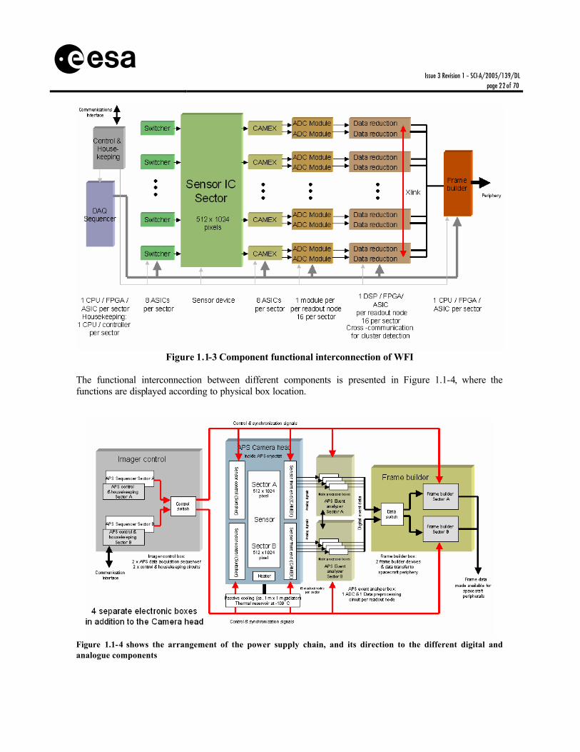
Figure 1.1-3 Component functional interconnection of WFI
The functional interconnection between different components is presented in Figure 1.1-4, where the functions are displayed according to physical box location.
Figure 1.1-4 shows the arrangement of the power supply chain, and its direction to the different digital and analogue components

Issue 3 Revision 1 – SCI-A/2005/139/DL
page 23 of 70
s
Figure 1.1-5 A similar organization, showing the lines for control and housekeeping for the subsystems.
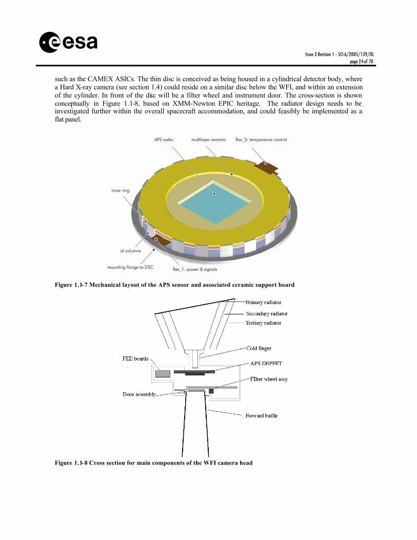
Figure 1.1-6 A similar organization chart, showing the lines for power supplies and lines for the subsystems. A conceptual drawing of the mechanical layout is provided in Figure 1.1-7. The central blue square represents the APS. It is mounted onto a multi- layer ceramic board that contains the front end electronics
Issue 3 Revision 1 – SCI-A/2005/139/DL
page 24 of 70
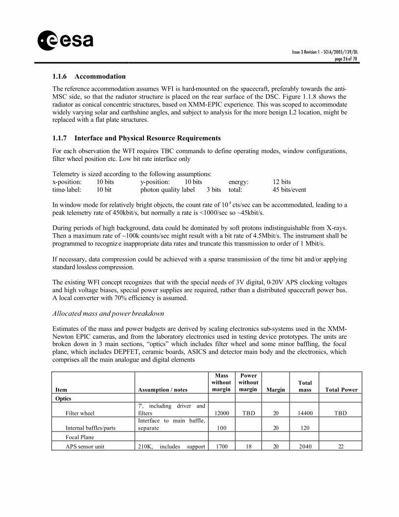
s such as the CAMEX ASICs. The thin disc is conceived as being housed in a cylindrical detector body, where a Hard X-ray camera (see section 1.4) could reside on a similar disc below the WFI, and within an extension of the cylinder. In front of the disc will be a filter wheel and instrument door. The cross-section is shown conceptually in Figure 1.1-8, based on XMM-Newton EPIC heritage. The radiator design needs to be investigated further within the overall spacecraft accommodation, and could feasibly be implemented as a flat panel.
Figure 1.1-7 Mechanical layout of the APS sensor and associated ceramic support board
Figure 1.1-8 Cross section for main components of the WFI camera head

Issue 3 Revision 1 – SCI-A/2005/139/DL
page 25 of 70
s 1.1.3 Operations
The WFI will be launched with the experiment body evacuated and a closed front-covering door which will be opened and remain open once a suitable outgassing period has completed. The focal plane should remain at TBD temperature elevated above normal operating temperature until suitable out-gassing is complete. The Filter wheel position may be selected per observation according to necessity for additional optical light-blocking, for calibration source deployment or for safety. Safety operations may be required autonomously or via ground control to prevent excessive charged particle fluence (solar flare or local magnetospheric storms), micrometeorite protection or spacecraft attitude loss. Internal calibrations will occur frequently to ensure the stability of instrument calibration with respect to system X-ray energy-ADC gain function etc. This can be via special observations with appropriate filter wheel location, and most efficiently during spacecraft slew.
Operating modes
The WFI instrument will be operating by execution of a limited number of predefined observation sequences that the spacecraft receives at a previous communication window. The science modes will define both the instrument operating sequence and the data processing requirements. Typical modes will be: Full Frame Image, Large Window Image and Point Source Timing.
1.1.4 Pointing Requirements
Pointing requirements are driven by the need for reconstituting images photon-by-photon to better than the accuracy of the optics FWHM performance, and timescales of reconstruction knowledge appropriate to the image time resolution (~1ms). Absolute Measurement Accuracy (AMA) (post facto)
Position centroiding of sources must be 0.5 arc seconds TBC
Relative Pointing Error (RPE) Assuming jitter at AMA scale is slow compared with drift, then relative pointing drift can be ~10 arcsec over minutes. Indeed a programmed raster drift at this scale is beneficial to science analysis.
Absolute Pointing Error (APE) To ensure that a target is acquired in a preferred location on the focal plane, an acquisition accuracy of better than 15 arc seconds is required.
Long term attitude stability A similar figure applies to pointing error accumulated over a long observation (defined here as 3 days TBC) ~15 arc seconds.
Note: all figures assumed ½ cone 90% excursions. Defocusing: for some bright point sources it may be advantageous to defocus the image so that photons are spread over more pixels and pile-up is reduced. Assuming spreading of the source across a 128x128 pixel detector window, then the defocusing should be ~50-100mm and achieved by along axial translation of the DSC.
1.1.5 Thermal
The detectors should operate at 210°K and be stabilized to ±0.1°K to ensure stability of on-chip electronics gain. Cooling via passive radiator (TBC) will allow the science operating temperature to be reached. The temperature should be within ±TBD°K of absolute value determined from ground calibration tests.
Issue 3 Revision 1 – SCI-A/2005/139/DL
page 26 of 70
s 1.1.6 Accommodation
The reference accommodation assumes WFI is hard-mounted on the spacecraft, preferably towards the anti-MSC side, so that the radiator structure is placed on the rear surface of the DSC. Figure 1.1.8 shows the radiator as conical concentric structures, based on XMM-EPIC experience. This was scoped to accommodate widely varying solar and earthshine angles, and subject to analysis for the more benign L2 location, might be replaced with a flat plate structures.
1.1.7 Interface and Physical Resource Requirements
For each observation the WFI requires TBC commands to define operating modes, window configurations, filter wheel position etc. Low bit rate interface only Telemetry is sized according to the following assumptions: x-position: 10 bits y-position: 10 bits energy: 12 bits time-label: 10 bit photon quality label 3 bits total: 45 bits/event In window mode for relatively bright objects, the count rate of 10 4 cts/sec can be accommodated, leading to a peak telemetry rate of 450kbit/s, but normally a rate is <1000/sec so ~45kbit/s. During periods of high background, data could be dominated by soft protons indistinguishable from X-rays. Then a maximum rate of ~100k counts/sec might result with a bit rate of 4.5Mbit/s. The instrument shall be programmed to recognize inappropriate data rates and truncate this transmission to order of 1 Mbit/s. If necessary, data compression could be achieved with a sparse transmission of the time bit and/or applying standard lossless compression. The existing WFI concept recognizes that with the special needs of 3V digital, 0-20V APS clocking voltages and high voltage biases, special power supplies are required, rather than a distributed spacecraft power bus. A local converter with 70% efficiency is assumed.
Allocated mass and power breakdown
Estimates of the mass and power budgets are derived by scaling electronics sub-systems used in the XMM-Newton EPIC cameras, and from the laboratory electronics used in testing device prototypes. The units are broken down in 3 main sections, “optics” which includes filter wheel and some minor baffling, the focal plane, which includes DEPFET, ceramic boards, ASICS and detector main body and the electronics, which comprises all the main analogue and digital elements
Item Assumption / notes
Mass without margin
Power without margin Margin
Total mass Total Power
Optics
Filter wheel 7', including driver and filters 12000 TBD 20 14400 TBD
Internal baffles/parts Interface to main baffle, separate 100 20 120
Focal Plane
APS sensor unit 210K, includes support 1700 18 20 2040 22

Issue 3 Revision 1 – SCI-A/2005/139/DL
page 27 of 70
s plate
Detector body To be clarified, assumed as cryostat 5000 20 6000
Temperature sensor Different locations on focal plane 60 20 72
Harness Detector to read-out unit, 32 lines, 20 cm 320 20 384
Heat strap Only interface, 10 cm long, 5 mm th, Cu 225 20 270
Shielding 3000 20 3600
Electronics 2 sectors duplicating electronics
APS Event Analyser 16000 96 20 19200 115
Housing APS EA 8400 20 10080
Frame builder 1 per sector each of 3 cards 1200 6 20 1440 7
Housing Frame Builder 25x20x10 cm 1700 20 2040 Imager Control Unit (including temperature control) 4 eurocards, TBC 800 48 20 960 58 Housing Imager Control Unit 20x15x10 cm 1200 20 1440 Power Supply 10 Eurocards per sector 4000 20 4800 Housing Power Supply unit 35x25x15 cm3 3150 20 3720
Harness Interconnections between units 843 20 480
TOTAL Kg/W 59.7 168 71.0 202 Table 1.1-1 Mass and power breakdown excluding dc-dc converter efficiency
Allocated instrument volume
TBD
1.1.8 Cleanliness, Ground Operations and Other Requirements
Cleanliness requirements Molecular contamination must be guaranteed to be small compared with effects of X-ray transmission filter performance. At energies of interest (50eV and 275 eV), a hydrocarbon build up with attenuation length of 0.1 microns implies a change in efficiency of 10% (which already affects useful calibration) at end of life, can be guaranteed with molecular contamination level a few 10-7 cm2/g. During all ground operations WFI will be closed by a door mechanism that will allow purging with clean gas. Precautions adopted for XMM-EPIC seem to have been successful at this comparable level.
Issue 3 Revision 1 – SCI-A/2005/139/DL
page 28 of 70
s Particulate contamination is not a strong driver – the fractional coverage area must be small compared with efficiency values. However, electrically shorting particles must be avoided completely.
1.1.9 Open Points and Critical Issues
1. Thermal concept: End of life performance may be dominated by radiation damage induced build up of dark current. This will determine the eventual target operating temperature. It is expected to be ~210K worst case. Depending also on developments in the front end electronics and operating requirements, the power to be dissipated at the cold stage is not yet well-known. The concept for packaging instruments around the WFI may also determine the power to be rejected at the radiator.
2. APS DEPFET detector: The DEPFET detector is baselined, but significant development is required
towards the space qualification of a suitable array. Lab prototypes with required performance exits, larger arrays and representative array sequencing need to be demonstrated
3. Light blocking coatings : Deposition of suit able aluminium light blocking filters direct on the
DEPFET entrance window needs to be demonstrated.
4. Baffling : The detector size of WFI is driving the sizing of the instrument baffle, leading to the largest baffle unit on the spacecraft. The presently size is the maximum compatible with a realistic DSC design. Additional work is required to define further the baffle requirements and potential design.

Issue 3 Revision 1 – SCI-A/2005/139/DL
page 29 of 70
s
1.2 Narrow Field Imager 1 (NFI 1) The purpose of the NFI 1 is to provide spectra with resolving power E/dE~500 in the energy range 0.2-6keV, simultaneously with images of a modest field of view and with time resolved photon counting. The instrument is expected to be ideally suited to the lower end of the energy range. The NFI 1 is based around a superconducting absorber with Superconducting Tunnel Junction (STJ) readout. Each X-ray photon releases photoelectrons on absorption, and eventually all carriers result in a quasiparticle cloud that is detected by a tunnelling current at the junction readout. In its simplest form the STJ based detector has one absorber and junction set per pixel. To maximize spatial coverage while minimizing readout connections, a “Distributed Read Out Imaging Detector” (DROID) scheme is preferred, in which signals are compared in ju nctions at the end of an absorber strip. The relative signal magnitudes then provide spatial location.
1.2.1 Scientific Goals
§ High spectral resolution follow-up of unusual objects down to flux ~ 10-16 ergs cm -2 s-1. § Spatially resolved spectra of moderately extended objects § High spectral resolution investigation of moderately bright point sources to time resolution
<millisecond
1.2.2 Instrument concept
The detector would consist of 10 detector rows of width 750µm, each with 50 150µm wide DROID strips. To allow for the connectors the detector rows are separated by 75µm. Each DROID strip has an absorber of free area 600 x 150µm between two 75x150µm STJs.
Figure 1.2-1 STJ DROID strip layout

Issue 3 Revision 1 – SCI-A/2005/139/DL
page 30 of 70
s Figure 1.2-1 shows the suggested layout of individual detector strips Tantalum is currently well developed, and would offer ~2eV resolution with a substantially easier operating temperature of 300mK. The detector size would be 7.5mm square providing a 0.75 arc min square field of view for a 35 m focal length. A block diagram of the instrument, highlighting all major sub-systems is shown in Figure 1.2-2.
Figure 1.2-2 NFI 1subsystems block diagram
A baffle cone restricts the field of view of the STJ elements to the telescope physical envelope only. This function is partly supplied by the cryostat body itself. As part of this baffling function, a set of light blocking filters are introduced in the optical path placed at TBD convenient cold points to prevent optical and thermal load from impinging the detector assembly. These are fixed filters of thin aluminised plastic (~100nm polymide and 40nm aluminium typically). The outermost filter will be at around the spacecraft operating temperature. Additionally a filter wheel will be mounted externally to provide additional light/thermal blocking as well as potentially calibration positions. A one time open door is required to protect against contamination. Low intensity (~100 gauss) magnetic coils are placed near the detector head in order to optimise the detector biasing. The detector array would be cooled by the last cryogenic stage. In Figure 1.2-2 this is identified as a sorption cooler, which is compatible with a Ta detector. Stirling and Joule-Thompson mechanical coolers are baselined as the pre-cooler elements. For a baseline of 500 absorber strips, there need to be 1000 channels of preamplifiers that are operated at room temperature, and must be located close (<30cm) from the detector head. The wiring harness passes through cold stage anchor points to minimize heat load to the array. There are two STJ readouts per strip absorber. The two signals are preamplified, and the signals shaped and peak-hold processed. The magnitude and rise-time are compared for the two signals, first of all to define acceptable signals and reject cosmic ray events. The magnitudes are then analysed to determine the position along the strip, while the addition of signals provides the event energy. Strip number (1 to 500), y location, energy and time, together with TBD quality flags are stored for transmission.

Issue 3 Revision 1 – SCI-A/2005/139/DL
page 31 of 70
s 1.2.3 Operations
The NFI will be launched with the experiment body evacuated. The filter wheel will be utilised to prevent excessive charged particle fluence (solar flare or local magnetospheric storms), or protect for micrometeorites or spacecraft attitude loss. Autonomous Safe mode will be required in addition pre-programmed command. Internal calibrations will occur frequently to ensure the stability of instrument calibration with respect to system X-ray energy-ADC gain function etc. This can be via special observations with appropriate filter wheel position, and most efficiently during spacecraft slew.
Operating modes
The NFI 1 instrument will be operating by execution of a limited number of predefined observation sequences to be stor ed in the spacecraft DPU that the spacecraft receives at a previous communication window. The science modes will define both the instrument operating sequence and the data processing requirements. Typical modes will be: Full Frame Imaging Spectroscopy and Point Source Timing.
1.2.4 Pointing Requirements
Pointing requirements are driven by the need for reconstituting images photon-by-photon to better than the accuracy of optics FWHM performance, and timescales of reconstruction knowledge appropriate to the image t ime resolution (~100µs) Absolute Measurement Accuracy (AMA) (post facto)
Position centroiding of sources must be 0.5 arc seconds TBC
Relative Pointing Error (RPE) Assuming jitter at AMA scale is slow compared with drift, then relative pointing drift can be ~10 arc seconds over minutes. Indeed a programmed raster drift at this scale is beneficial to science analysis.
Absolute Pointing Error (APE) To ensure that a target is acquired in a preferred location on the focal plane, an acquisition accuracy of better than 10 arc seconds is required (PSF guaranteed to be within NFI field).
Long term attitude stability A similar figure applies to pointing error accumulated over a long observation (defined here as 3 days TBC) ~10 arc seconds.
Note: All figures assumed ½ cone 90% excursions.
1.2.5 Thermal
The detector temperature should be stabilized to ±TBC °mK to ensure stability of system gain. The temperature should be within ±TBD°mK of the absolute value determined from ground calibration tests.
1.2.6 Accommodation
The NFI 1 is hard-mounted on the spacecraft, preferably towards the anti-MSC and anti-solar panel sides, so that the radiator structure is placed on the coldest surface of the DSC, and the distance from focal point is minimised. The radiator requirements will be based on a detailed study of the cryogenic chain.

Issue 3 Revision 1 – SCI-A/2005/139/DL
page 32 of 70
s 1.2.7 Interface and Physical Resource Requirements
It is assumed that the mechanical pre-coolers will be operating continuously. Subject to cryochain design activity the final target operating temperature may also be permanently acquired. For each observation the NFI requires TBC commands to define operating modes, window configurations, door position etc. Low bit rate interface only In the basic mode of operation telemetry is sized according to: Strip number: 8 bits y-position: 4 bits energy: 14 bits time-label: 10 bit Quality Flag 2 bits total: 38 bits/event Maximum point count rate is expected to be 2x10 4 cts/sec, leading to a peak telemetry rate of 760kbit/s, generally with source rates 1000s-1 the typical telemetry rate will be 38kb/s. During periods of high background, data could be dominated by soft protons which are indistinguishable from X-rays. Then a maximum rate of ~300k counts/sec might result with a bit rate of 9Mbit/s. However at such sustained rates, the signal recovery time likely prevents useful spectroscopic data being retained, so that the instrument likely inhibits at some predetermined rate the transmission at such high data rates to circa 1Mb/s. If necessary data compression could be achieved with a sparse transmission of the time bit and/or applying standard lossless compression. Allocated mass and power breakdown
Unit description Assumptions / notes Mass without
margin (g)
Power without margin
(W) Margin
(%) Total
mass (g)
Total Power
(W)
Optics
Filter wheel Outside cryostat 1000 5 20 1200 6
Thin filter/s At each intermediate Temperature 150 20 180
Focal Plane
Detector/s Single assembly, including connector 100 20 120
Detector cold-plate Cu, 5 cm diameter, 1 cm thick 100 20 120
Temperature sensor Integrated on cold plate 20 20 24
Harness 1m, 1000 signal lines + 50 return 100 20 120
Bias coil SC magnet with bore of 50 mm diam 4000 20 4800
Ancillary hardware e.g. integrated thermal / mag shield 200 20 240
Electronics
Front-End Electronics (FEE) 50 Eurocards 10000 10 20 12000 12
Housing FEE 35x30x25 cm3 4800 20 5760
Analog processing ADCs 80 Eurocards over 2 housings 16000 20 20 19200 24
Housing ADC's 2 of 35x25x25 cm3 8400 20 10080
Back-End Electronics (BEE) 40 Eurocards 8000 30 20 9600 36
Housing BEE 35x25x25 cm3 4200 20 5040
Data Processing Unit (DPU) 6 Eurocards 1200 6 20 1440 7
Housing DPU 15x20x15 cm3 1400 20 1680

Issue 3 Revision 1 – SCI-A/2005/139/DL
page 33 of 70
s Magnet Power Supply / DC-
DC 5 Eurocard 1000 5 20 1200 6
Housing Power unit 20x15x15 cm3 1400 20 1680
T sensor 4x on each box 200 20 240
Harness 3 % of electronics 1086 20 1303
TOTAL kg / W 63.36 76 76.03 91
Table 1.2-1 Mass and power breakdown for NFI1 excluding dc-dc converter efficiency
Allocated instrument volume
TBD
1.2.8 Cleanliness, Ground Operations and Other Requirements
Cleanliness requirements Molecular contamination must be guaranteed to be small compared with effects of X-ray transmission filter performance. For instance within the energy range a Carbon line at 275 eV will be affected by a hydrocarbon build up. An attenuation length of 0.1 microns implies a change in efficiency of 10% (already af fects useful calibration) at end of life. Consequently the molecular contamination level should be below a few 10-7 cm2/g. During all ground operations NFI will allow purging with clean gas. Precautions adopted for XMM-EPIC seem to have been successful at this comparable level, but trapped cryogens between successive cold light-blocking filters must be avoided.
1.2.9 Open Points and Critical Issues
1. Thermal concept: should system resources allow the installation of both NFI1 and NFI2, these units may be able to share part of the cryogenic chain (e.g. intermediate cryostat thermal shields, pre-cooling stage). Depending on final detector characteristics, NFI1 may require an ADR instead of a Sorption Cooler, thus opening the possibility for a duplication of the system used for NFI2.
2. STJ detector: Lab prototypes in Ta have been demonstrated, but with some unknown additional
noise factor that prevents reaching theoretical achievable energy resolution. The use of Mo detectors could potentially improve resolution although implying a lower operating temperature, calling for an ADR based system. Development of DROIDs of optimum size and close packing must be demonstrated. The choice of absorber affects energy range and the operating temperature.
3. Light blocking filters : Deposition of suitable aluminium light blocking filters on thin plastic must be
developed and minimized so that 3 to 4 thermal stage filters can be accommodated

Issue 3 Revision 1 – SCI-A/2005/139/DL
page 34 of 70
s
1.3 Narrow Field Imager 2 (NFI 2) The purpose of the NFI 2 is to provide spectra with resolving power E/dE of several hundred in the energy range 0.2 – 6keV, simultaneously with images of a modest field of view and with time resolved photon counting. The NFI 2 is based around an absorber with transition edge sensor (TES) readout. Each X-ray photon on absorption, releases heat, and the temperature change in the low heat capacity absorber is sensed by the TES.
1.3.1 Scientific Goals
§ High spectral resolution follow-up of unusual objects down to flux ~ 10-16 ergs cm -2 s-1. § Spatially resolved spectra of moderately extended objects § High spectral resolution investigation of moderately bright point sources with time resolution ~ few
millisecond
1.3.2 Instrument concept
The detector will be based upon square Bismuth/Copper absorbers as depicted in Figure 1.3-1.
Figure 1.3-1 Cross section of a single pixel, showing absorber mushroom placed on top of TES thermometer
The baseline format of the Focal Plane Array corresponds to a 32x32, 240 micron square pixels, with a total field of view of 45 x 45 arcsec2 (35m focal length). While a larger format array (i.e. a larger FOV) would be highly beneficial from a science point of view, it is recognised that at the present level of technology, larger focal plane sizes are not realistic, also in relation to the added complexity of the corresponding read-out electronics. The possibility to baseline larger arrays will be re-assessed at a later stage. The detection efficiency is determined by an absorber thickn ess of 7 microns Bismuth, allowing 90% efficiency up to ~7 keV. Energy resolution at 6 keV has been demonstrated at ~ 2-3eV FWHM in bolometer prototypes, but arrays read out via multiplex techniques still have to be fully demonstrated. The resolution requirements for the array are 2 eV FWHM at TBD and 4 eV FWHM at 6 keV for the central array and the surrounding arrays, respectively.

Issue 3 Revision 1 – SCI-A/2005/139/DL
page 35 of 70
s The cryogenic sensor array has no particle background rejection capability in itself. Due to the rather shallow 7µm deep pixels in relation with the rather large pixel size of 240, µm anti-coincidence techniques turn out highly inefficient, while the minimum energy deposited in the sensor absorber is in the middle of the sensitive range. To enable sky limited background oper ation, especially important for sensitive cluster observations, an anti-coincidence shield will be required directly under the imaging pixel array. The anti-coincidence for a micro-calorimeter experiment just launched on the Astro-E2 satellite is a single large area PIN diode of 1 x 1 cm2 area and 0.5 mm thickness made of high Ohmic (13 -21 kO.cm at room temperature) silicon. Good metallic contacts are made on both surfaces by Phosphorous and Boron implantation on either side and subsequent deposition of aluminium contacts. The sensor operates well, with a charge signal resolution of about 200 eV, at mK temperatures with a bias voltage in the range of 2 – 8 V. The charge signal is actually read-out by two (for redundancy) cold (90 K) J-FETs in source follower configuration and a warm amplifier outside the cryostat. The signals are sent to a comparator and anti-coincidence logic. Signals received by the micro-calorimeter array get an anti-coincidence flag added in the case they are coincident with a signal in the anti-coincidence detector. A block diagram of the instrument, highlighting all major sub-systems is shown in Figure 1.3-2. The science instrument is built up from three electronics boxes, the Squid Electronics Box (SEB) containing the SQUID Flux-Lock-Loop Electronics, the Bias Supply and Signal Read-out unit (BSSR) and the Instrument Control Unit (ICU). The SEB has to be situated as close as possible to the TES array, and should be rigidly mounted onto the cryostat for EMC rejection. The SEB allows RF multiplexing of the signals from many pixels to be readout in parallel, thus reducing the number of thermal connectors.
Figure 1.3-2 Schematic of the NFI2 instrument. Crucial is the short distance of the SEB unit to the focal plane and its rigid attachment to the cryostat in order to suppress EMC. The entrance window and baffle are aligned along the cryostat length direction, but a perpendicular radiation entrance is possible as well. The baffle is drawn conceptually and might actually have quite a different layout.

Issue 3 Revision 1 – SCI-A/2005/139/DL
page 36 of 70
s The array requires operation at temperatures ~50mK, and the baseline cooling is provided by an ADR pre-cooled itself by a J-T and Stirling cooler pair. The detailed design will be subject to further accommodation studies. Figure 1.3-3 shows more detail of the sub-system inter-connections
Frequencysynthesizer.
Instrument.Processor
Filterwheel/door
control
J-T Stirling
Electronics(2 boxes)
Command&
HK interface
Powerinterface
&conditioning
De-modulation,event detection
&signal
processing
SQUIDs
1 K & 4 K
Controlalg.
NegativeFeedback
AC biassourcedrive
SQUIDbias
A/Dconverters
Cryostat
SQUID FLL electronics box Bias supply& signal read-out unit
s/c power
s/c bus
Instrument controlunit
s/c bus
Instr. control
Housekeeping
Housekeeping
Cryo-housekeeping Sec. power & control
Detectorarray
40 mK
Filters
40 mK
1024
Datainterface
35 mK
2-stage
0.8 K
ADR
2.5 or 4 K
Compressor
20 K
Compressor
Filterwheel/door
EM
I filt
ers
S/C
bus
ses
(pow
er, O
BD
H e
tc)
s/c bus
Preamp
Sec. power
Figure 1.3-3 Detailed functional block diagram of NFI 2
1.3.3 Operations
The NFI will be launched with a closed front-covering door, and experiment body evacuated. After suitable out-gassing period of the spacecraft the door shall be opened. The filter wheel should be closable to prevent excessive charged particle fluence (solar flare or local magnetospheric storms), or protect for micrometeorites or spacecraft attitude loss. Autonomous Safe mode may be required in addition pre-programmed command. Internal calibrations will occur frequently to ensure the stability of instrument calibration with respect to system X-ray energy-ADC gain function etc. This can be via special observation in appropriate filter wheel position, and most efficiently during spacecraft slew.

Issue 3 Revision 1 – SCI-A/2005/139/DL
page 37 of 70
s Operating modes
The NFI 2 instrument will be operating by execution of a limited number of predefined observation sequences to be stored in the spacecraft DPU that the spacecraft receives at a previous communication window. The science modes will define both the instrument operating sequence and the data process ing requirements. Typical modes will be: Full Frame Imaging Spectroscopy and Point Source Timing
1.3.4 Pointing Requirements
Pointing requirements are driven by the need for reconstituting images photon-by-photon to better than the accuracy of optics FWHM performance, and timescales of reconstruction knowledge appropriate to the image time resolution (~1ms) Absolute Measurement Accuracy (AMA) (post facto)
Position centroiding of sources must be 0.5 arc seconds TBC
Relative Pointing Error (RPE) Assuming jitter at AMA scale is slow compared with drift, then relative pointing drift can be ~10 arc seconds over minutes. Indeed a programmed raster drift at this scale is beneficial to science analysis.
Absolute Pointing Error (APE) To ensure that a target is acquired in a preferred location on the focal plane, an acquisition accuracy of better than 10 arc seconds is required (PSF guaranteed to be within NFI field).
Long term attitude stability A similar figure applies to pointing error accumulated over a long observation (defined here as 3 days TBC) ~10 arc seconds.
Note: All figures assumed ½ cone 90% excursions.
1.3.5 Thermal
The focal plane should remain at ~50mK. This cryochain will be the subject of more detailed design. The temperature should be stabilized to ±TBC°K to ensure stability of system gain. Temperature should be within ±TBD°K of absolute value determined from ground calibration tests. The entrance baffle will include thin filters with the upper most filter around spacecraft operating temperature.
1.3.6 Accommodation
The NFI 2 is hard-mounted on the spacecraft, preferably towards the anti-MSC and anti-solar panel side, so that the radiator structure is placed on the coldest surface of the DSC, and distance from focal point is minimised. The radiator requirements will be based on detailed study of the cryogenic chain.
1.3.7 Interface and Physical Resource Requirements
It is assumed that the mechanical pre-coolers will be operating continuously. Subject to cryochain design activity the final target operating temperature may also be permanently acquired. For each observation the NFI requires TBC commands to define operating modes, window configurations, door position etc. Low bit rate interface only. In the basic mode of operation each event will be defined by:
Issue 3 Revision 1 – SCI-A/2005/139/DL
page 38 of 70
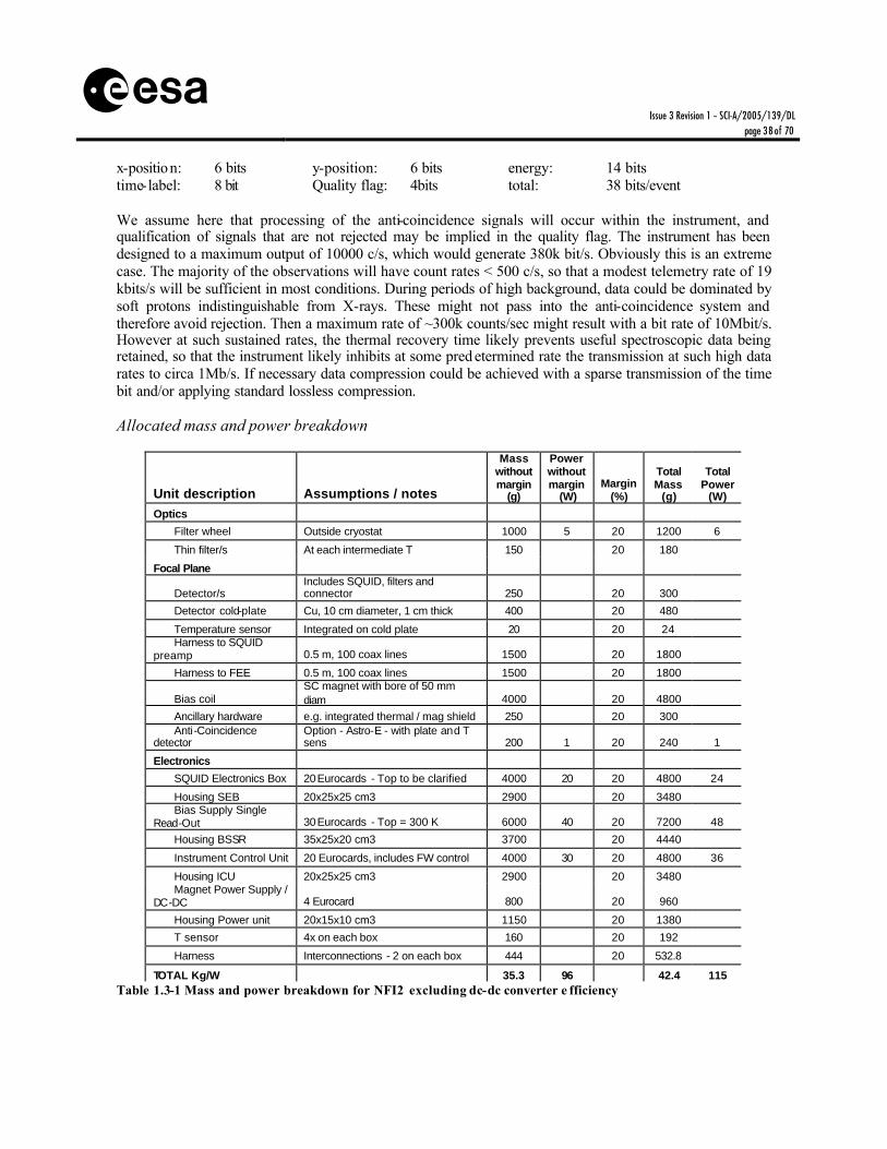
s x-position: 6 bits y-position: 6 bits energy: 14 bits time-label: 8 bit Quality flag: 4bits total: 38 bits/event We assume here that processing of the anti-coincidence signals will occur within the instrument, and qualification of signals that are not rejected may be implied in the quality flag. The instrument has been designed to a maximum output of 10000 c/s, which would generate 380k bit/s. Obviously this is an extreme case. The majority of the observations will have count rates < 500 c/s, so that a modest telemetry rate of 19 kbits/s will be sufficient in most conditions. During periods of high background, data could be dominated by soft protons indistinguishable from X-rays. These might not pass into the anti-coincidence system and therefore avoid rejection. Then a maximum rate of ~300k counts/sec might result with a bit rate of 10Mbit/s. However at such sustained rates, the thermal recovery time likely prevents useful spectroscopic data being retained, so that the instrument likely inhibits at some pred etermined rate the transmission at such high data rates to circa 1Mb/s. If necessary data compression could be achieved with a sparse transmission of the time bit and/or applying standard lossless compression.
Allocated mass and power breakdown
Unit description Assumptions / notes
Mass without margin
(g)
Power without margin
(W) Margin
(%)
Total Mass
(g)
Total Power
(W)
Optics
Filter wheel Outside cryostat 1000 5 20 1200 6
Thin filter/s At each intermediate T 150 20 180
Focal Plane
Detector/s Includes SQUID, filters and connector 250 20 300
Detector cold-plate Cu, 10 cm diameter, 1 cm thick 400 20 480
Temperature sensor Integrated on cold plate 20 20 24 Harness to SQUID
preamp 0.5 m, 100 coax lines 1500 20 1800
Harness to FEE 0.5 m, 100 coax lines 1500 20 1800
Bias coil SC magnet with bore of 50 mm diam 4000 20 4800
Ancillary hardware e.g. integrated thermal / mag shield 250 20 300 Anti-Coincidence
detector Option - Astro-E - with plate and T sens 200 1 20 240 1
Electronics
SQUID Electronics Box 20 Eurocards - Top to be clarified 4000 20 20 4800 24
Housing SEB 20x25x25 cm3 2900 20 3480 Bias Supply Single
Read-Out 30 Eurocards - Top = 300 K 6000 40 20 7200 48
Housing BSSR 35x25x20 cm3 3700 20 4440
Instrument Control Unit 20 Eurocards, includes FW control 4000 30 20 4800 36
Housing ICU 20x25x25 cm3 2900 20 3480 Magnet Power Supply /
DC-DC 4 Eurocard 800 20 960
Housing Power unit 20x15x10 cm3 1150 20 1380
T sensor 4x on each box 160 20 192
Harness Interconnections - 2 on each box 444 20 532.8
TOTAL Kg/W 35.3 96 42.4 115 Table 1.3-1 Mass and power breakdown for NFI2 excluding dc-dc converter e fficiency

Issue 3 Revision 1 – SCI-A/2005/139/DL
page 39 of 70
s
Allocated instrument volume
TBD
1.3.8 Cleanliness, Ground Operations and Other Requirements
Cleanliness requirements Molecular contamination must be guaranteed to be small compared with effects of X-ray transmission filter performance. For instance within the energy range a Carbon line at 275 eV will be affected by a hydrocarbon build up. An attenuation length of 0.1 microns implies a change in efficiency of 10% (already affects useful calibration) at end of life. Consequently the molecular contamination level should be below a few 10-7 cm2/g. During all ground operations NFI2 will be closed by a door mechanism that will allow purging with clean gas. Precautions adopted for XMM-EPIC seem to have been successful at this comparable level, but trapped cryogens between successive cold light-blocking filters must be avoided.
1.3.9 Open Points and Critical Issues
1. Thermal concept: actual location of SQUID based electronics and related cooling requirements need to be assessed in conjunction with the design of the cryogenic chain. Should system resources allow the installation of both NFI1 and NFI2, these units may be able to share part of the cryogenic chain (e.g. intermediate cryostat thermal shields, pre-cooling stage).
2. TES detector : Lab prototypes have been demonstrated, but theoretically achievable energy
resolution has not been demonstrated yet. Development of larger format, closely packed arrays and related read-out electronics needs demonstration.
3. Light blocking filters : Deposition of suitable aluminium light blocking filters on thin plastic
must be developed that 3 to 4 thermal stage filters can be accommodated
4. SQUID Multiplexers : RF multiplexing and biasing has been demonstrated, but needs further development to show efficient operation of large arrays with correct bandwidth and noise performance can be achieved
5. Anti-coincidence: Sensitivity in energy range >2keV will be limited by charged particle
background. A concept for efficient background rejection using a modest cryo-cooled anti-coincidence system behind the high aspect ratio pixel design must be considered and tested.
6. Enlarged Field Of View: A possibility for a larger FOV detector is envisioned to be
organised into 9 arrays in a 3x3 formation, thus giving a larger field of view. To achieve the required field of view and the spatial resolution a compromise is required where the central array has smaller pixels to provide better spatial resolution. Nevertheless, based on the

Issue 3 Revision 1 – SCI-A/2005/139/DL
page 40 of 70
s present level of technology maturity, the extension of the focal plane size should be balanced against increased complexity and development risk.

Issue 3 Revision 1 – SCI-A/2005/139/DL
page 41 of 70
s
Part 3 Description of the Ancillary Instruments

Issue 3 Revision 1 – SCI-A/2005/139/DL
page 42 of 70
s
1.4 Hard X-ray Camera (HXC) The purpose of the HXC is to provide spectra with resolving power E/dE of 10% in the energy range 15 – 80keV, simultaneously with images of a field of view of ~5 arcmin, and with time resolved photon counting. The HXC is based around a compound semiconductor array of pixels, read out by an ASIC. In order to suppress background, an active anticoincidence shield is deployed around the imager.
1.4.1 Scientific Goals
§ Detection and imaging of absorbed AGN and XRB populations in nearby galaxies down to fluxes ~10-13 ergs cm-2 s-1. (20-60keV)
§ Spatially resolved (10 arcsec) spectra of moderately extended objects to detect shocked components in clusters and SNR’s
§ High energy continuum spectra and timing of bright objects observed by the WFI
1.4.2 Instrument concept
The HXC employs an array of compound-semiconductor pixel detectors read out by front ASICs bump bonded to pixel electrodes underneath the semiconductor wafer. The detector is based on highly uniform Cadmium Telluride (CdTe) semiconductor. The baseline considers a 3 x 3 array of CdTe pixel detectors. Each detector has 32 x 32 pixels with a pixel size of 480 micron by 480 micron. This corresponds to a 5 arc minute square field of view and an imaging capability of 4.75 arcsec with a 35 m focal length.

Issue 3 Revision 1 – SCI-A/2005/139/DL
page 43 of 70
s
Figure 1.4-1 Geometry of the detectors in the HXC focal plane A thickness of at least 0.5 mm of CdTe gives us an ability to detect X-ray photons up to 40 keV with 100 % efficiency. The signal from each pixel is processed individually by analog chains implemented in the ASIC. Either a combination of Charge Sensitive Amplifier and Shaping Amplifier or a Time-over-Threshold architecture will be used in the ASIC. According to the measurement by prototype detectors, an energy resolution of better than 1 keV (FWHM) can be achieved in the energy range from 10 keV to 80 keV when we operate the detector at 220K. The CdTe detector mounted in the HXC is shielded by a BGO (Bi4 Ge3O12) scintillator. This shield is indispensable, as the non X-ray background is the dominant source of the background in the energy range of the HXC. A thickness of ~2 cm for BGO will be required, not only for shielding against background photons but also for reducing the number of particles that reach the CdTe detector and give rise to activation.
Figure 1.4-2 O verview of the sub-system of HXC
From the Power Supply Unit (PSU), high voltage supplies are required to present the bias necessary for the CdTe detectors and the Avalanche PhotoDiodes (APD) of the anticoincidence shields. The shields’ readout by the APDs requires 8 charge sensitive amplifiers (CSA) and analogue electronics chains. Each block of 3 CdTe ASICS is followed by analogue processing electronics to make event selection and censoring, energy and position assignment etc., before digitalisation and passing to the digital electronics.
1.4.3 Operations
The HXC will be launched with a closed front-covering door, and experiment body evacuated. After suitable out-gassing period of the spacecraft the door shall be opened.
Issue 3 Revision 1 – SCI-A/2005/139/DL
page 44 of 70
s The door should be closable to prevent excessive charged particle fluence (solar flare or local magnetospheric storms), or protect for micrometeorites or spacecraft attitude loss. Autonomous Safe mode may be required in addition pre-programmed command. Internal calibrations will occur frequently to ensure the stability of instrument calibration with respect to system X-ray energy-ADC gain function etc. This can be by special observations with an appropriate door position, and most efficiently during spacecraft slew.
Operating modes
The HXC instrument will be operating by execution of a limited number of predefined observation sequences to be stored in the spacecraft DPU that the spacecraft receives at a previous communication window. The science modes will define both the instrument operating sequence and the data processing requirements. Typical modes will be: Full Frame Imaging Spectroscopy, Window Mode Imaging Spectroscopy and Point Source Timing.
1.4.4 Pointing Requirements
Pointing requirements are driven by the need for reconstituting images photon-by-photon to better than the accuracy of optics FWHM performance, and timescales of reconstruction knowledge appropriate to the image time resolution (~1ms) Absolute Measurement Accuracy (AMA) (post facto)
Position centroiding of sources must be 1 arc second TBC
Relative Pointing Error (RPE) Assuming jitter at AMA scale is slow compared with drift, then relative pointing drift can be ~10 arc seconds over minutes. Indeed a programmed raster drift at this scale is beneficial to science analysis.
Absolute Pointing Error (APE) To ensure that a target is acquired in a preferred location on the focal plane, an acquisition accuracy of better than 15 arc seconds is required.
Long term attitude stability A similar figure applies to pointing error accumulated over a long observation (defined here as 3 days TBC) ~15 arc seconds.
All figures assumed ½ cone 90% excursions.
1.4.5 Thermal
The focal plane should remain at ~220K. The temperature should be stabilized to ±TBC°K to ensure stability of system gain. Temperature should be within ±TBD°K of absolute value determined from ground calibration tests.
1.4.6 Accommodation
The depth of focus allows the HXC to be slightly out of the nominal focal position, for example the HXC energy band requirement for angular resolution ~ 10 arcsec could allow ~35 (TBC)mm displacement along the telescope axis. The HXC requires a hard mounting on the spacecraft utilising a dedicated passive radiator for cooling the detector to the operating temperature.
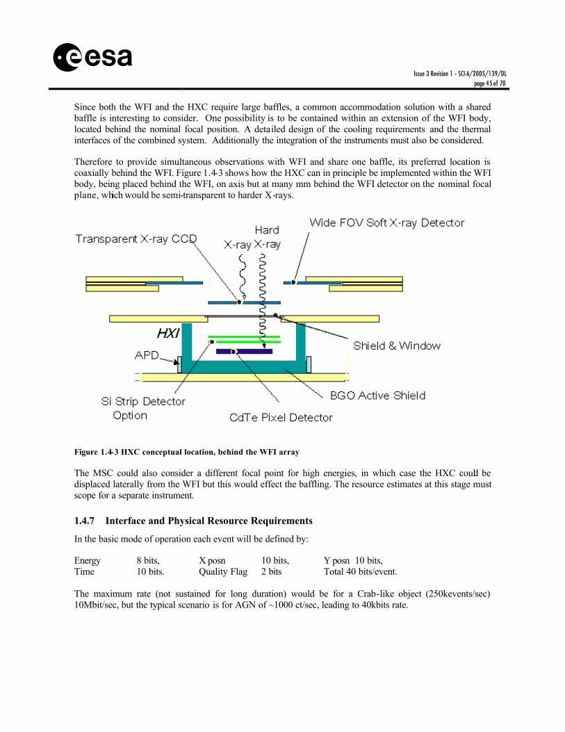
Issue 3 Revision 1 – SCI-A/2005/139/DL
page 45 of 70
s Since both the WFI and the HXC require large baffles, a common accommodation solution with a shared baffle is interesting to consider. One possibility is to be contained within an extension of the WFI body, located behind the nominal focal position. A detailed design of the cooling requirements and the thermal interfaces of the combined system. Additionally the integration of the instruments must also be considered. Therefore to provide simultaneous observations with WFI and share one baffle, its preferred location is coaxially behind the WFI. Figure 1.4-3 shows how the HXC can in principle be implemented within the WFI body, being placed behind the WFI, on axis but at many mm behind the WFI detector on the nominal focal plane, which would be semi-transparent to harder X-rays.
Figure 1.4-3 HXC conceptual location, behind the WFI array The MSC could also consider a different focal point for high energies, in which case the HXC could be displaced laterally from the WFI but this would effect the baffling. The resource estimates at this stage must scope for a separate instrument.
1.4.7 Interface and Physical Resource Requirements
In the basic mode of operation each event will be defined by: Energy 8 bits, X posn 10 bits, Y posn 10 bits, Time 10 bits. Quality Flag 2 bits Total 40 bits/event. The maximum rate (not sustained for long duration) would be for a Crab-like object (250kevents/sec) 10Mbit/sec, but the typical scenario is for AGN of ~1000 ct/sec, leading to 40kbits rate.

Issue 3 Revision 1 – SCI-A/2005/139/DL
page 46 of 70
s During periods of high background, data could be dominated by energetic protons indistinguishable from X-rays. Then a maximum rate of ~300k counts/sec might result with a bit rate of 10Mbit/s. Before reaching this rate, the quality flags and/or ASIC performance will have truncated and limited throughput to circa 1 Mbit/s. If necessary data compression could be achieved with a sparse transmission of the time bit and/or applying standard lossless compression.
Allocated mass and power breakdown
Item Assumption/notes Unit mass (g)
Unit Power (W)
Design maturity
(%)
Total Mass (g)
Total Power
(W) Optics
Filter Anti fluorescence between WFI
50 20 60
T sensors 2 at filter 20 20 24 Focal Plane
Detector CdTe & ASIC 500 6 20 600 7 Detector plate Support ceramic 200 20 240 Temp sensor Several 20 20 24 Harness Flexi circuits 160 20 192 BGO scintillator 4 200 20 5 040 APD and P/A 2 000 20 2 400 Detector housing 5 000 20 6 000
Electronics Analog electronics 3 000 9 20 3 600 11 Anti-co electronics Incl box and power 5 000 6 20 6 000 7 Power unit HV 3 000 1 20 3 600 1 Digital electronics CPU, I/F memory 5 000 6 20 6 000 7 PSU Housing 35 x 20 x 15 cm 4 100 20 4 920 DE Housing 35 x 25 x 15 cm 4 800 20 5 760 Harness 3% electronics 480 20 576
TOTAL 38 kg 28 45 kg 33 Table 1.4-1 Mass and power breakdown for HXC excluding dc-dc converter efficiency
Allocated instrument volume
TBD
1.4.8 Cleanliness, Ground Operations and Other Requirements
Cleanliness requirements

Issue 3 Revision 1 – SCI-A/2005/139/DL
page 47 of 70
s Molecular contamination must be guaranteed to be small compared with effects of X-ray transmission filter performance. At energies of interest (10keV and above), this is not a problem. During all ground operations the HXC will have the door closed and will allow purging with clean gas. If mounted within the WFI, then cleanliness requirements should be driven by the need to avoid contaminating the WFI volume.
1.4.9 Open Points and Critical Issues
1) Location in/out of WFI: This choice will mainly be driven by eventual hard X-ray effective area of the mirrors, and whether the hard response is to be provided by a separate system or by multi-layer coatings of the nominal XEUS telescope. Following that decision the HXC may be located within or outside the WFI system. The integrated option brings some savings in overall mass efficiency, but creates some difficult problems in integration and test, and needs careful design to ensure the background is not enhanced, and that the thermal design for 2 separate detectors is optimised.
2) Semiconductor detectors: the choice of material (CdZnTe, CdTe or GaAs) depends in part
on eventual energy range adopted. Spectral resolution, efficiency and radiation hardness are all in principle demonstrated on lab prototypes.
3) Readout ASIC: Again lab prototype ASIC readout has been demonstrated, but substantial
development is necessary to optimise on-chip functionality, reduce power dissipation and qualify for space use.
4) Anticoincidence: the minimization and power reduction of the anticoincidence system must
be demonstrated and the rejection efficiency confirmed.

Issue 3 Revision 1 – SCI-A/2005/139/DL
page 48 of 70
s
1.5 High Time Resolution Spectrometer (HTRS) The purpose of the HTRS is to provide spectra with resolving power E/dE of 5-50 in the energy range 0.5 to 10keV, at very high time resolution (10µs) and with very high count rate capability (2MHz). The HTRS is based around an array of silicon drift diodes.
1.5.1 Scientific Goals
§ Spectral resolution of 200eV FWHM for point sources with flux up to 5 Crabs. § Timing resolution of 10 µs with low and well-measured dead time.
1.5.2 Instrument concept
Figure 2.1.5.1 shows the typical structure of a single silicon drift diode. X-rays liberate photoelectrons in the Single Drift Diode (SDD) which are drifted very rapidly to a central single low noise Field Effect Transistor (FET ) amplifier.
Figure 1.5-1 Concept of a single drift diode X-ray spectrometer
Figure 1.5-2 Matrix of 19 SDD cover a field of about 1cm 2, from 5mm2 elements each. The detector must not be at the telescope focal point as the PSF must be defocused to smooth the photon distribution more or less equa lly across the diodes. This implies being ~150mm prior to the focus point.

Issue 3 Revision 1 – SCI-A/2005/139/DL
page 49 of 70
s The instrument comprises three units, which must be arranged so that the Detector Electronic Unit (DEU) is within 20 cm of the Detector Unit. The DEU needs to be located <1m from the Central Electronic Unit (CEU).
Figure 1.5-3 Functional block diagram of HTRS instrument The DEU comprises essentially a fast spectroscopy preamplifier for each SDD channel. The bandwidth of processing circuits will be tuned as a compromise between good energy resolution and fast sampling. However a fast peaking time allows for smaller degradation in energy resolution with count rate (due to pile -up effects). Baseline designs assume a shaping time of 150ns, with an accurately measured dead time between 0.5 and 1µs, and a time resolution of 10 µs. The energy range of the electronics is defined as 0.5-50keV. Event selection and digitisation occurs before passing signals to the CEU. The CEU provides switching control and power supplies to the DEU and SDDs. The data are multiplexed from 19 channels into one stream with time tags and passed with TBD compression to the spacecraft telemetry store. The Detector unit should be located on a cooling finger/interface to allow active control to ~260K to ±0.1K TBC. The diodes require moderate high voltage ~150V. Use of discrete preamplifiers has been baselined, but mass effective highly integrated ASICS would be preferred, especially to minimize the footprint around the SDD area.
1.5.3 Operations
The HTRS will be launched with a closed front-covering door (or use WFI door), and experiment body evacuated. After suitable out-gassing period of the spacecraft the door shall be opened. The door should be closeable to prevent excessive charged particle fluence (solar flare or local magnetospheric storms), or protect for micrometeorites or spacecraft attitude loss. Autonomous Safe mode may be required in addition pre-programmed command. Internal calibrations will occur frequently to ensure the stability of instrument calibration with respect to system X-ray energy-ADC gain function etc. This can be via special observations in appropriate door position, and most efficiently during spacecraft slew.

Issue 3 Revision 1 – SCI-A/2005/139/DL
page 50 of 70
s Operating modes
The HTRS instrument will be operating by execution of a limited number of predefined observation sequences to be stored in the spacecraft DPU that the spacecraft receives at a previous communication window. The science modes will define both the instrument operating sequence and the data processing requirements. Typical modes will be: Point Source Timing and Histogrammed Timing
1.5.4 Pointing Requirements
Pointing requirements below are driven by the need for reconstituting the acceptance fraction of the defocused beam on the diode array. Absolute Measurement Accuracy (AMA) (post facto)
Position centroiding of sources must be 1 arc second TBC
Relative Pointing Error (RPE) Assuming jitter at AMA scale is slow compared with drift, then relative pointing drift can be ~10 arc seconds over minutes.
Absolute Pointing Error (APE) To ensure that a target is acquired in a preferred location on the focal plane, an acquisition accuracy of better than 10 arc seconds is required.
Long term attitude stability A similar figure applies to pointing error accumulated over a long observation (defined here as 3 days TBC) ~10 arc seconds.
All figures assumed ½ cone 90% excursions. Defocusing: The HTRS is normally used for bright point sources and it is necessary to defocus the image so that photons are spread more or less evenly over all pixels of the instrument. Assuming the source should be spread across the 19 diodes, then the defocusing should be ~150mm and achieved by along axial translation of the DSC and/or hard location of the detector unit in front of the nominal WFI plane.
1.5.5 Thermal
The focal plane SDDs should remain at ~260K. The temperature should be stabilized to ±0.1 TBC°K to ensure stability of system gain. Temperature should be within ±TBD°K of absolute value determined from ground calibration tests. Thermal design depends on whether integrated with WFI or not.
1.5.6 Accommodation
The HTRS could be hard-mounted on the spacecraft as an individual instrument or integrated with the WFI. Integration with WFI could be as an extension of the WFI body, located next to the nominal focal position within the WFI baffle which with a 36.5cm MSC skirt is 71.5cm in diameter . A detailed design of the thermal requirements of the combined system is necessary including interfacing with the WFI cold ceramic base. In addition the baffling of the HTRS in combination with the WFI within the same body needs to account for minimization of extraneous background into the WFI from the HTRS baffling cone.

Issue 3 Revision 1 – SCI-A/2005/139/DL
page 51 of 70
s
Figure 1.5-4 Possible layout for HTRS when accommodated within the WFI detector body. Vertical displacement for defocusing can be traded against defocusing by displacement of the whole spacecraft for HTRS observations.
1.5.7 Interface and Physical Resource Requirements
For each observation the HTRS requires TBC commands to define operating modes, window configurations, door position etc. Low bit rate interface only Telemetry requirements defined as follows: Diode#: 5 bits energy: 6 bits time-label: 17 bit total: 28 bits/event At high count rates, the time label can be replaced with a time difference between successive events. With ~3 – 5 bits used to transmit differences at the 10µs resolution level, then the brightest sources have a substantially compressed data rate. The instrument has been designed to a maximum output of 2M c/s, which would generate 30M bit/s. The on-board storage should be sized for ~400Gbit to allow 10ksec observation to be stored for later retrieval at subsequent telemetry windows. These brightest sources are not expected to be observed for longer than 10ks, but some fainter pulsed targets might be observed for longer with lower bit rate.
Issue 3 Revision 1 – SCI-A/2005/139/DL
page 52 of 70
s A second form of compression would be to collect spectra for given time bins. For example 2MHz count rate in 64 spectral bins every 100 µs is accommodated in 7bits*1e4*64channels = 4Mbit/s before compression.
Allocated mass and power breakdown
Item Assumption/notes Unit mass (g)
Unit Power (W)
Margin (%)
Total Mass (g)
Total Power
(W) Optics
Additional baffles Interface only 500 20 600 Focal Plane 0
Detector Plate & SDDs 2000 10 20 2400 12 Temp sensor Several 60 20 72 Harness Flexi circuits 120 20 144
Electronics 0 Detector
electronics 10 eurocard 2000 30 20 2400 36
housing DE 15x15x25cm3 2000 2000 Central electronics 20 eurocards 4000 30 20 4800 36 housing CE 25x25x20cm3 2900 2900 Harness 3% electronics 180 20 216
TOTAL Kg/ W 13.8 70 15.5 84 Table 1.5-1 Mass and power breakdown for HTRS. a) Does not include dc-dc converter efficiency
Allocated instrument volume
TBD
1.5.8 Cleanliness, Gro und Operations and Other Requirements
Cleanliness requirements
During all ground operations HTRS will be closed by a door mechanism that will allow purging with clean gas. If mounted within the WFI, then cleanliness requirements should be driven by the need to avoid contaminating the WFI volume.
1.5.9 Open Points and Critical Issues
1) Integration with WFI: The integration with WFI is efficient in terms of the WFI vendor also supplying equivalent technology within one ceramic package, however this needs careful consideration of optimal defocusing, and whether this is solely achieved by DSC translation. Integration and test philosophy must also be considered
2) Optimum temperature: TBC the temperature may be higher than WFI, say 260K.
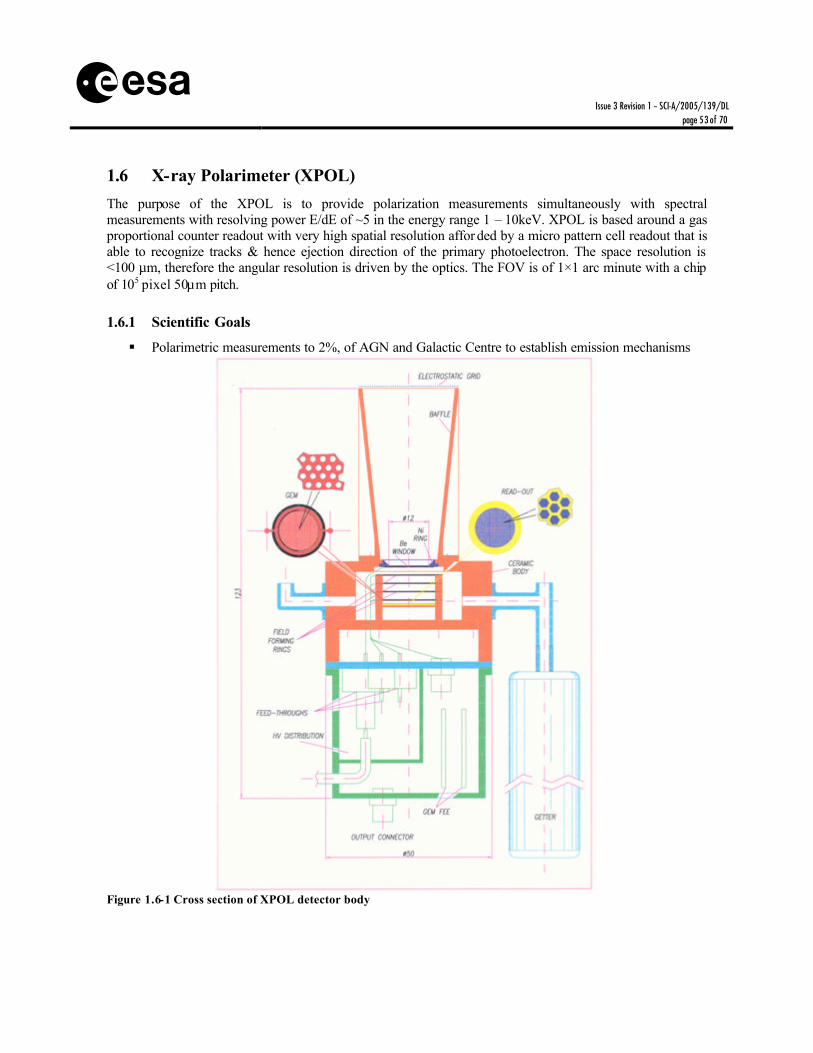
Issue 3 Revision 1 – SCI-A/2005/139/DL
page 53 of 70
s
1.6 X-ray Polarimeter (XPOL) The purpose of the XPOL is to provide polarization measurements simultaneously with spectral measurements with resolving power E/dE of ~5 in the energy range 1 – 10keV. XPOL is based around a gas proportional counter readout with very high spatial resolution affor ded by a micro pattern cell readout that is able to recognize tracks & hence ejection direction of the primary photoelectron. The space resolution is <100 µm, therefore the angular resolution is driven by the optics. The FOV is of 1×1 arc minute with a chip of 105 pixel 50µm pitch.
1.6.1 Scientific Goals
§ Polarimetric measurements to 2%, of AGN and Galactic Centre to establish emission mechanisms
Figure 1.6-1 Cross section of XPOL detector body

Issue 3 Revision 1 – SCI-A/2005/139/DL
page 54 of 70
s 1.6.2 Instrument concept
According to all data on aging of mixtures based on noble gases with various quenching, included DME (testing aimed to LHC experiments), XPOL gas mixtures can accommodate the radiation damage levels foreseen for XEUS. The major problem is the long term pollution of the mixture. Since a long experience exists on sealed gas counters operated in space for years, there is a firm confidence that, with the procurement of very pure gas and a proper selection of materials to be used inside the detector gas cell the problem can be solved. The Gas Electron Multiplier (GEM) is a metal-coated Kapton film, similar to that used in Stellar X-Ray Polarimeter (SXRP) detectors. Long term stability in a sealed gas cell with Beryllium window was achieved not only for proportional counters (e.g. COS-B, HEAO-1, Einstein, GINGA, XTE) but also for GSPC (TEMNA, ASCA, SAX) which are extremely sensitive to pollution from out-gassing. Thus the detector is a sealed body with no gas replenishment system.
Figure 1.6-2 Functional block diagram of the XPOL sub-systems The detector is self-standing and has its own baffle built in. The Gas Cell has as baseline a gas filling at 1 Atm Ne (50%) DME (50%) with 10 mm absorption/drift gap. Based on studies in progress the pressure could be increased to 2 Atm to improve the efficiency especially at higher energies. The mixture could also be substituted with other mixtures less sensitive to lateral diffusion during drift to allow for thicker absorption/drift gap. In this case the overall length could increase of 10mm. The baseline window is 50µm of Beryllium. In case technology shows that an improved performance can be achieved at energies below 1.5 keV a thin plastic window could be adopted. Interconn ections from Detector/FEE block to CE block are expected as in the following table.
Connection # HV shielded cables 4 3 for detector plus 1 for electrostatic grid Space Wire cable 2 For fast transfer of scientific data and control FEE and
Detector Low Voltage wires 9 Power Supplies Low Voltage wires 2 For safety data to be forwarded to P/L DU

Issue 3 Revision 1 – SCI-A/2005/139/DL
page 55 of 70
s
Figure 1.6-3 Functional block diagram of the XPOL electronics sub-systems The readout ASIC can be implemented with an existing “chip III” that appears already suitable for XPOL. It includes self -triggering capability and only data within a window around the trigger pixel are fetched to the output. This means that the signal from the GEM will be only used to determine the energy. The signal to noise ratio for a single electron converted in the gas is 5σ . Critical High Voltage systems are described in Table 1.6-1. ? V Nominal
Volts Range Volts
Current µA
Regul. bits
Stability % in the
whole T range
Ripple mV
Ramp Up
Volt/s
Ramp Down Volt/s
Vdrift = Vw-VGup 1000 2000÷700 20 4 2 500 pk to pk
100 200
Vmultiplication = VGdown
- VGup 500 350÷600 1 8 0.5 100
pk to pk 10 10
V = VGdown - Vpad 300 100÷400 20 8 0.5 100 pk to pk
10 10
Table 1.6-1 High Voltage Power Supply for XPOL
Insulation
Inner electrodes (and window) insulated from the detector body. Window, GEMup, GEMdown connected to HVPS with independent HV shielded cables. HV return on the socket. HV and ASIC grounded together within IE. Field Forming Rings HV internally formed by voltage divider. It is required a stacked HVPS, namely a separate regulation of the differences of potential. Electrostatic Grid: +3kV with independent HVPS, insulation from the baffle. HV return on the shield. HV shielded cable sustained by the baffle. Baffle electrically connected to the detector body.

Issue 3 Revision 1 – SCI-A/2005/139/DL
page 56 of 70
s 1.6.3 Operations
The XPOL will be launched with a closed front-covering door. After suitable out-gassing period of the spacecraft the door shall be opened. The door should be closeable to prevent excessive charged particle fluence (solar flare or local magnetospheric storms), or protect for micrometeorites or spacecraft attitude loss. Autonomous Safe mode may be required in addition pre-programmed command. Internal calibrations will occur frequently to ensure the stability of instrument calibration with respect to system X-ray energy-ADC gain function etc. This can be via special observations in appropriate door position, and most efficiently during spacecraft slew.
Operating modes
The XPOL instrument will be operating by execution of a limited number of predefined observation sequences to be stored in the spacecraft DPU that the spacecraft receives at a previous communication window. The science modes will define both the instrument operating sequence and the data processing requirements. Typical modes will be: Polarimeter and Test Imaging, High Data rate post-processing For normal operational mode, for a large majority of sources, data are A/D converted and time tagged events. Event tracks are analysed on ground. In bright source mode, data are A/D converted and stored on the XPOL mass memory. While XEUS is performing an observation with another instrument data are recovered from the XPOL mass memory. Tracks are analysed onboard (assumed to be performed within XPOL as the software is specialised and computing intensive) and only compressed information (time, energy, polarization, quality parameters for each event) is stored in the mass memory ready to be transferred to the spacecraft on request. The XPOL mass memory is dimensioned to store data from a 2 hours observation of a 1Crab source. The processing time will be significant and normally less than 50 times that of the acquisition time. The data flow for a very bright source could arrive to ~5Mbit/s for a total memory occupation of 35Gb.The processing to compress data could take ∼ 4 days. After compression it would reduce to ∼ 12 Gb, which could be downloaded over subsequent telemetry windows at suitably lower rate interleaved with normal science data, or special communications windows requested for this download. This means that after the pointing of a very bright source XPOL cannot be operated for around one week.
1.6.4 Pointing Requirements
Pointing requirements are driven by the need to accurately locate the point sources into the detector field of view. Timescales of reconstruction knowledge appropriate to the image time resolution (~1ms) Absolute Measurement Accuracy (AMA) (post facto)
Position centroiding of sources must be 1 arc second TBC
Relative Pointing Error (RPE) Assuming jitter at AMA scale is slow compared with drift, then can be ~15 arc seconds over minutes.
Absolute Pointing Error (APE) To ensure that a target is acquired in a preferred location on the focal plane, an acquisition accuracy of better than 15 arc seconds is required.
Long term attitude stability A similar figure applies to pointing error accumulated over a long observation (defined here as 3 days TBC) ~15 arc seconds.
Note: All figures assumed ½ cone 90% excursions.

Issue 3 Revision 1 – SCI-A/2005/139/DL
page 57 of 70
s 1.6.5 Thermal
The focal plane should remain at 280K (±40K). The temperature should be stabilized to ±TBC°K to ensure stability of system gain. Temperature should be within ±TBD°K of absolute value determined from ground calibration tests.
1.6.6 Accommodation
The XPOL is hard-mounted on the spacecraft, with no special location requirements
1.6.7 Interface and Physical Resource Requirements
For each observation the XPOL requires TBC commands to define operating modes, window configurations, door position etc. Low bit rate interface only In track-resolved data mode, the data will comprise Energy 4 bits, X posn 4 bits, Y posn 4 bits, Time 14 bits, Total 26 bits/event. Total 10-20 events/photon After on-board track recognition the polarisation track data can be reduced to 6 bits, and 1 event per photon The maximum rate (not sustained for long duration) would be for a Crab-like object (250kevents/sec) 7.5Mbit/sec, but the typical scenario is for AGN of ~1000 ct/sec, leading to 300kbits rate. A very bright source is very necessary to be observable, because these may be limiting cases for measuring polarimetery, and for which polarimetery offers interesting source physics diagnosis. In these cases (see section 1.6.3) the data will be stored in the XPOL Mass Memory for ∼ 1 - 2 hours. This is sufficient for all the scientific requirements. Data can be compressed onboard and transmitted off-line.

Issue 3 Revision 1 – SCI-A/2005/139/DL
page 58 of 70
s
Allocated mass and power breakdown
Item Assumption/notes Unit mass (g)
Unit Power
(W)
Margin Total Mass (g)
Total Power
(W)
Optics Door Motor, filters from XMM 1000 10 1100
Internal baffles Interface only 100 20 120 Focal Plane 0
GEM detector and body 12 x 5cm dia 3000 20 3600
Temp sensor Several 60 20 72
Harness Flexi circuits 150 20 180
Electronics 0
FEE Accommodated in detector envelope
1000 2 20 1200 2.4
HVPS TBD eurocards 2000 2 20 2400 2.4
DPU TBD eurocards 9000 25 20 10800 30
Mass Memory 35 Gbits EOL 3000 7 25 3750 8.75
PSU TBD 4000 12 20 4800 14.4
Housing HVPS 35x25x15 cm3 3100 20 3720 Housing DPU 35x25x15 cm3 3100 20 3720 Housing PSU 20x15x15 cm3 1500 20 1800
T sensor 4x on each box 120 20 144
Harness Interconnections - 2 on each box 570 20 684
TOTAL kg / W 31.7 48 38.1 58 Table 1.6-2 Mass and power breakdown for XPOL excluding dc-dc converter efficiency
Allocated instrument volume
TBD
1.6.8 Cleanliness, Ground Operations and Other Requirements
Cleanliness requirements
During all ground operations XPOL will be closed by a door mechanism that will allow purging with clean gas.

Issue 3 Revision 1 – SCI-A/2005/139/DL
page 59 of 70
s 1.6.9 Open Points and Critical Issues
1) The study of the optimal gas mixture, thickness and field, to improve the factor of merit µ×ε1/2 (where µ is the modulation factor and ε is the efficiency) that determines the sensitivity of the instrument. This is also needed to tune the polarimeter performance with the band pass of the telescope.
2) The study of possible minor changes in the auto-triggered fetch window of the ASIC in order to improve data rate for very bright sources.
3) The study of the optimal algorithms of track analysis to improve the sensitivity 4) The selection of materials to be employed inside the gas cell to ensure long term stability of the gas
mixture. 5) Radiation test of all the components. 6) Post observation data processing concept

Issue 3 Revision 1 – SCI-A/2005/139/DL
page 60 of 70
s
Part 4 Payload Accommodation and Interfaces

Issue 3 Revision 1 – SCI-A/2005/139/DL
page 61 of 70
s
1 INTRODUCTION
Payload accommodations and relevant interfaces to the XEUS DSC spacecraft are described in the following sections. The identification of a resource-efficient configuration will be crucial in the context of the system level XEUS design in view of meeting two main goals: a) ensure compatibility with programmatic constraints especially for defining clean interfaces for cryogenic sub-systems b) optimise the resource usage so that the mission can be made as affordable as possible, and especially maximise the resources (mass) devoted to the optics sub-system on the MSC. The accommodation of instruments in the DSC will be subject to a dedicated industrial study. The information contained in this chapter is therefore preliminary.
Issue 3 Revision 1 – SCI-A/2005/139/DL
page 62 of 70
s
2 ACCOMODATION
The XEUS DSC will fly in formation with the MSC and due to thermal constraints both on the MSC and the DSC the formation will be viewing in a direction perpendicular to the sun with a max-off pointing of 15(TBC) degrees. This allows one side of the spacecraft to be permanently hot and the other side to be cold, thus having one side ideally suited for radiators. As most instruments would prefer a cold environment it would be beneficial to mount the instruments towards the anti-sun side. As the spacecraft can off-point from the Sun it might be necessary to have an extended sun shield to limit the heat coming from the Sun into the instruments. This would in particular be valid for the NFI1 and the NFI2. Constraints deriving from the installation of the large WFI baffle are expected to condition the overall payload accommodation.

Issue 3 Revision 1 – SCI-A/2005/139/DL
page 63 of 70
s
3 PAYLOAD SUPPORT ELEMENTS (PSE)
To simplify the interfaces between the payload and the spacecraft, and to achieve savings in mass, cost and risk, the concept of Payload Support Elements are addressed. The PSE are procured separately from any scientific instrument but are required for a proper accommodation on-board (e.g., baffles, cryogenics and mass memory storage). Presently the PSE items are considered as ESA provided and the following are currently envisaged: Payload Support Element
Description / justification Nominal Mass (kg)
Margin (%)
Total Mass (kg)
Cryogenics A parallel redundant mechanical cooler system that acts as an efficient pre-cooler for either NFI instrument. The final cooling stage of the instrument could be as a sorption cooler or ADR.
145 (sorption cooler) /
195 (ADR)
20 174 (sorption cooler) /
234 (ADR)
Baffles Provide an efficient baffling solution to baffle all instruments, so that baffling can be comprised of both MSC and DSC functionalities.
36 for WFI
20 44
Mass memory storage Data storage for science data collected between telemetry communications windows (~Gbytes) is required. A common data storage will be used for all instruments.
3.6 20 4.3
TOTAL 184 – 234 20% 221-281

Issue 3 Revision 1 – SCI-A/2005/139/DL
page 64 of 70
s
4 INTERFACES
4.1 Data handling system The spacecraft shall provide the main data handling system with which the instruments shall communicate. The interface shall be from the instrument via Spacewire. The spacecraft shall provide mass storage that can be used for the storage of telemetry by all instruments.
4.2 Power
The spacecraft is in charge of delivering protected primary power at 28V. It is assumed that a distributed approach to DC/DC conversion shall be adopted. Some instruments need a wide range of low voltage and high voltage supplies for detector operation, and the conversion efficiency has not been accounted for so far in the power tables in Part 2. The number of instruments needing simultaneous operating power levels is restricted to those in the focus of the MSC. The other instruments must be kept in standby state, which includes full operation of the cryogenics.
4.3 Thermal The instrument compliment on the XEUS detector spacecraft has a wide range of thermal requirements, from the cryogenic instruments NFI1 and NFI2, to the cold WFI and the room temperature instruments such as XPOL. The required temperatures for the all the instrument detectors are shown in the below table. Item Operating temperature Dissipation (W) WFI focal plane 210 K 22 WFI electronics 290 K 180 NFI1 detector 300 mK 0 NFI1electronics 290 K 91 NFI2 detector 50 m K 0 NFI2 electronics 290 K 115 H XC focal plane 220 K 7 H XC electronics 290 K 26 HTRS focal plane 250 K 12 HTRS electronics 290 K 72 XPOL all elements 290 K 58 Total dissipation 582.95
Table 4.3-1 Temperature requirements and dissipations for the instruments It is currently assumed that all instruments except from the NFI1 and NFI2 can be cooled passively. To cool the NFI1 and NFI2 cryogenic coolers are required.

Issue 3 Revision 1 – SCI-A/2005/139/DL
page 65 of 70
s 4.4 Cryogenics It is currently envisioned that only one NFI instrument will be used for XEUS. The cooling system might therefore be different depending on the selected instrument. In a possible design scenario both instruments could utilize the same pre-coolers to obtain 2.5 K. This pre-cooling could be achieved by using a 2 stage Joule-Thompson (JT) Stirling cooler as shown in Figure 4.4-1. The first stage of this cooler is a Stirling cycle pre-cooler enabling temperatures of about 20 K with an intermediate step a 100 K. The JT closed cycle cooler uses 3He as a working fluid and is capable of providing a temperature of 2.5 K. To provide the different working temperatures of the two NFI instruments two different concepts are envisioned:
a) To provide the 300 mK for NFI1 a sorption cooler is baselined, similar to that used by several instruments on Herschel.
b) 50 mK for NFI2 is obtained by using a continuous Adiabatic Demagnetisation Refrigerator (ADR). The estimate of the resources is based on a scaling from the current ADR under development from Mullard Space Science Laboratory (MSSL).
Figure 4.4-1 Basic architecture of a 2 stage JT Stirling cooler

Issue 3 Revision 1 – SCI-A/2005/139/DL
page 66 of 70
s It is currently assumed that the cryogenic chain is fully redundant. The resource estimate includes therefore two fully independent cooler chains. It is assumed that if redundancy is kept throughout the project that no flight spare is produced for any of the cooler elements, thus reducing the number of delivered items. The redundancy philosophy will be subject to further trade later in the project. Hence using the resources for a fully redundant cooler system would be a worst-case scenario. The resources required for the entire cryogenic dual redundant chain is showed in Table 4.4-1.
Unit Mass (w. ADR) (kg)
Power (w. ADR) (W)
Mass (w. Sorption) (kg)
Power (w. Sorption) (W)
20K Stirling cooler 53.1 184.8 53.1 184.8 2.5K JT unit 65.6 199.2 65.6 199.2 Sorption cooler NF1 - - 8.9 12.0 ADR cooler NF2 65.6 120.0 - - Harness 9.2 0 7.9 0 Cryostat 40.1 0 40.1 0 DC/DC loss (10%) 0 57.3 0 57.3 Total (ADR) 233.6 554.4 174.2 435.6
Table 4.4-1 Resources for a potential cryogenic chain including margins
4.4.1 Thermal interfaces
Each instrument is assumed to have different interfaces to dedicated radiators. The focal planes of the non-cryogenic instruments need to operate below room temperature and will have a direct cold finger interface to a radiator, thus allowing passive cooling. The elements that can be at room temperatures, such as instrument control electronics, power supplies etc. are assumed to be commonly controlled with the rest of the spacecraft components with room temperature radiators. Using this interface philosophy the following radiator sizes are calculated based on a full un-obstructed view to deep space. To limit the heat losses it is currently assumed that the coldest instruments are located on the anti-sun side.
4.5 Baffling In order to baffle stray X-ray and optical stray light, a baffle system forward of the instruments will ensure that the field of view minimizes unwanted light to the focal plane. The baffling will be divided between a skirt on the mirror on the MSC and baffles mounted in front of the instruments on the DSC. The larger the mirror skirt, the smaller the baffle needed on the DSC hence a detailed investigation on the optimum division of baffling is required. At this point it is assumed that the MSC has a mirror of 4.2 m diameter(TBC) and that the mirror will have a skirt of approximately 36cm. The baffle length is dependent upon the focal length, the mirror skirt size and the size of the detector. It is clear that the baffle length will be largest for the WFI,. For NFI1 / NFI2 the baffle would only need to be about 72cm. By placing the detectors towards the anti-viewing directions some of the baffle can be placed inside the DSC.

Issue 3 Revision 1 – SCI-A/2005/139/DL
page 67 of 70
s 4.5.1 WFI Baffle
For WFI the baffle will have to protrude outside the spacecraft structure. A fixed baffle would be a simple solution avoiding any deployable parts. The baffle would need to be able to attenuate sufficiently X-rays at 6 keV. This implies good coating for instance with 10 micron of gold. It is interesting to note that if the HXC is included in the payload, the baffle mass will increase substantially. This is due to the HXC having a prime interest at X-rays with higher energies and requiring a thicker layer of gold.
4.6 Pointing requirements
Here we describe the pointing requirements that are determined in combination with the Mirror and the Formation Flying Requirements.
4.6.1 Pointing Requirements
Based on the Mission Requirements Document [RD?], the XEUS spacecraft will provide pointing accuracy and stability according to the table below. In its operational orbit, the XEUS MSC spacecraft shall fulfil the pointing accuracy and stability requirements listed in Table 4.6-1 (TBC).
Requirement Pointing Parameter Line of Sight (ZOpt) Around Line of Sight
G-322-11a APE : Absolute Pointing Error < 2.4 arcsec < 30 arcsec R-322 -11a APE : Absolute Pointing Error < 5 arcsec < 1 arcmin R-322 -11b PDE : Pointing Drift Error < TBD arcsec /day < TBD arcmin /day R-322 -11c RPE : Relative Pointing Error < 2.4 arcsec / 1 day < TBD arcsec /day R-322 -11d AMA : Absolute Meas. Accuracy < 1 arcsec TBD
Table 4.6-1 The XEUS MSC Operational Pointing and Accuracy Requirements The driver for the pointing accuracy and stability of the DSC is the baffling of the detectors and the minimisation of straylight. The effects on the Point Spread Function and other characteristics also need to be considered.
In its operational orbit, the XEUS DSC spacecraft shall fulfil the pointing accuracy and stability requirements listed in Table 4.6-2 (TBC).
Requirement Pointing Parameter Line of Sight (Z Opt) Around Line of Sight
R-322-12a APE : Absolute Pointing Error < 60 arcsec < 30 arcmin Table 4.6-2 The XEUS DSC Operational Pointing and Accuracy Requirements Pointing requirements and goals are given as single axis rotation angles together with their associated 2(TBC)-sigma deviations, and are applicable until the end of the extended operational lifetime and total radiation dose. It should be noted that the celestial pointing is a system requirement for the telescope axis, and formation-flying places additiona l requirements on DSC lateral pointing.
Issue 3 Revision 1 – SCI-A/2005/139/DL
page 68 of 70
s 4.6.2 Mirror Alignment
The focal point of the X-ray mirrors shall in orbit be aligned to an accuracy of +/- 0.5mm (TBC) in all three dimensions.
The focal point and focal length shall be maintained to an accuracy of +/- 0.5mm (TBC) in all three dimensions.
4.6.3 Formation Flying Requirements
The DSC shall maintain the focal point of the mirror within +/- 3mm in the ZOpt plane of the specified detector.
The DSC shall maintain the focal point of the MSC within +/- 1mm of the centre of the specified detector.
The spacecraft shall be able to autonomously maintain the required telescope formation until commanded otherwise.

Issue 3 Revision 1 – SCI-A/2005/139/DL
page 69 of 70
s
5 ESA / PLATFORM PROVIDED ITEMS
Given their critical role on overall system performance, impact on the AIV/T schedule and close interfaces to the spacecraft subsystems, it is baselined that the cryogenic chain shall be procured via the prime as part of the S/C. This section provides a short overview of pos sible elements and technologies to be adopted in the design of the DSC cryogenic chain. It should be noted that the definition of the cryo-chain is subject of a specific industrial activity and the this information is to be considered for reference only and will be up-dated after the completion of the study.
5.1 Cryogenic Elements. The NFI1 and NFI2 use a set of coolers in order to achieve the required operating temperatures. These coolers and the associated cryostat shields and other elements are ESA/Platform provided items. This chapter provides brief description of these items.
5.1.1 20 K Stirling Cooler
This is a two stage Stirling cooler and provides sufficient cooling power to pre-cool the 2.5 K/4K cooler. It uses an intermediate shield at a temperature of about 100 K. The cooler is of same design to the one to be flown on Planck. This cooler will form the first stage in the overall cryogenic system and it is assumed that the cooler including its associated electronics and support elements will have a mass of about 52 kg and consume a power of 185 W
5.1.2 2.5 K Joule Thomson Cooler
This is a 3He-Joule Thomson cooler and it will provide the interface temperature to the two different final stages (the ADR and the sorption cooler). This 2.5 K is developed under a previous ESA contract and is based on the 4 K JT-cooler for the Planck mission. It is assumed that this stage would have a mass of 64 kg and consume about 200 W of power.
5.1.3 Sorption cooler
This sorption cooler is developed for Herschel and will be used for PACS and SPIRE. This sorption cooler uses 3He and is able to provide the final temperature of 300 mK, which is required for the STJ. This sorption cooler will use about 12 W of power and have a mass of approximately 9 kg.

Issue 3 Revision 1 – SCI-A/2005/139/DL
page 70 of 70
s
Figure 5.1-1 - Herschel sorption cooler
5.1.4 Adiabatic Demagnetisation Refrigerator
An Adiabatic Demagnetisation Refrigerator (ADR) is currently under development by ESA. The XEUS mission is currently assuming a further development of this cooler towards a continuous ADR that would allow continuous operation in full redundant mode. The continuous ADR would allow each unit some resource savings with respect to the current ADR. The mass of the continuous ADR is assumed to be 65.3 and consume 120 W of power.
Figure 5.1-2 ADR cooler currently under development